electrodynamics – science of electric charges in motion flow electric charges may occur: 1. in a...
TRANSCRIPT

Electrodynamics – Science of electric charges in motion
Flow Electric Charges May Occur:
1. In a vacum
2. In a gas
3. In ionic solution
4. In a metallic conductor

Sources of Electricity
1) Chemical
2) Mechanical
3) Solar
4) Atomic

Electric current flows in an electric circuit (the path over which currentflows)
The Three physical components of a circuit include:
1) Battery (source)2) Conductor3) Load (resistance)The switch – Current flows only when the switch is closed
Voltage exists even when the switch is open (be careful!)
Conductor

Three Factors That Characterize an Electric Circuit
1) Current (intensity) – Number of electrons flowing per second- Measured in amps or milliamps (A or mA)- Ampere – One coulomb quantity of electricity flowing per sec. (6.3 X 10¹⁰ electrons per sec)
2) Potential Difference - Also referred to as the electromotive force (EMF) or voltage drop
- Pressure or push behind the current- Measured in volts or kilovolts (V or kV)- Volt – That potential difference which will cause a current of one amp to flow in a circuit whose resistance is one ohm- Higher resistance leads to a larger voltage drop

3) Resistance – That property that impedes the flow of electrons- Measured in ohms
Three Factors That Characterize an Electric Circuit
Resistance Depends on Four Factors
1. Material
2. Length of material
3. Cross-sectional area
4. Temperature
Ω

Chemical Devices That Make Electricity
May be a dry cell or wet cell battery –
1) Dry Cell – Contains dry chemical along with an cathode (neg.) and anode (pos.)
2) Wet Cell – Contains wet chemical (i.e. sulfuric acid) with cathode and anode

More on Circuits
Polarity – Direction of current flow- Assumed to be negative to positive
Open Circuit – A circuit that is broken as some point
Closed Circuit – A circuit that is completed (unbroken)
Overloaded Circuit – Too much amperage causing over-heatingin circuit- Prevented by fuses

Two Types of Circuits
Series Circuit – One whose parts are arranged end-to-end
Parallel circuit – One whose parts are arranged as branchesoff the main circuit

Connecting Meters to Circuits
Voltmeter – Measures potential difference between two points ina circuit
- Must be connected in parallel to work properly
Ammeter – Measures the amperage in a circuit- Must be connected in series to work properly

Ohms Law – The value of a current in a resistance circuit supplied bydirect current (DC) is equal to the voltage divided by the resistance.
Ohm’s Law
Ohm – German physicist – Discovered the relationship betweenvoltage, amperage and resistance
I = V/RI= Intensity (A)V = Potential Difference (V)R = Resistance (Ohms)
May also be algebraically manipulated:V = I X RR = V/I
V
I R

Using Ohms Law
You can find out the voltage, amperage or resistance ifyou know 2 of 3 variables in a circuit
For example, what is the intensity of a circuit if there is 2 ohms of resistance and 10 volts?
Circuit has 10 V and2 ohms of resistance

Rules Differ by Circuit Type
1) Series Circuit- The amperage is the same everywhere in the circuit- The voltage and resistance is equal to the sum of the voltages and resistances of the circuit
2) Parallel Circuits:- The amperage differs in each branch, the smallest current flowing in the branch with the largest resistance. The total amperage is equal to the sum of currents provided
by all sources across all resistances- The voltage is the same across the entire circuit- The total resistance is equal to the reciprocal of the whole resistance of the sum of the reciprocals of the individual resistances in the circuit


Rule:The total resistance is equal to the reciprocal of the whole resistance of the sum of the reciprocals of the
individual resistances in the circuit
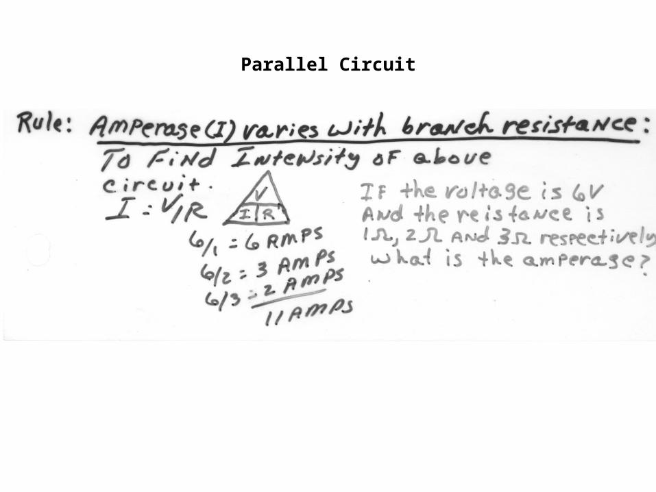
Parallel Circuit

Storing Electrical EnergyParallel Plate Capacitors
Capacitor – A device that stores electrical energy. - Used in various radiology devices (automatic exposure controls and mobile units)- Unit of capacitance – farad- Composed of:
1. Two metal plates 2. Dielectric (i.e., air) between plates3. Battery source 4. Conductor

Method of Operation:1) The plates are connected to a battery.2) Electrons pass from the neg. battery terminal to the plate to which it’s connected3) An equal number of electrons pass from the opposite plate to the positive battery terminal
Parallel Plate Capacitor
4) When fully charged, voltage ceases to flow from source5) Capacitor is disconnected and retains its charge until connected to a conductor.6) The capacitor discharges in the opposite direction as the original charging current

The Work and Power of DC Current
Power – The amount of work current can do per sec.Power is stated in Watts or KilowattsP (Watts) = I X VP = PowerI = Intensity of current in (A)V = Voltage (V)
Examples 20 A X 60 V = 1200 Watts 200 mA X 60,000 = .2 A X 60,000 = 12,000 Watts (12 KW)

Power Loss
Power is lost in the transmission of power and in x-ray equipment due to heat loss!- Also state in WattsPL (Watts) = I2 X RPL = Power loss (Watts)I2 = Intensity squaredR = Resistance
Example:How much power loss results in an electric line carrying 20 amps and2 ohms of resistance?Answer:20 X 20 X 2 = 800 Watts