electrodialysis and ion-exchange membrane systems dev groups... · iii b116-5 tjm committee...
TRANSCRIPT
B116-5 tjm i
American Water Works Association
ANSI/AWWA B116-xx (First Edition)
AWWA STANDARD
FOR
Electrodialysis and Ion-Exchange Membrane
Systems
Draft:
April 2014
Effective date:_______________________
This edition approved ____________________________.
Approved by American National Standards Institute ______________________________.
This document is the property of the American Water Works Association (AWWA)
and is for AWWA committee purposes only. Unless given prior approval from
AWWA, it shall not be reproduced, circulated, or quoted, in whole or in part, outside
of AWWA.

B116-5 tjm ii
AWWA Standard This document is an American Water Works Association (AWWA) standard. It is not a specification. AWWA
standards describe minimum requirements and do not contain all of the engineering and administrative
information normally contained in specifications. The AWWA standards usually contain options that must be
evaluated by the user of the standard. Until each optional feature is specified by the user, the product or service
is not fully defined. AWWA publication of a standard does not constitute endorsement of any product or product
type, nor does AWWA test, certify, or approve any product. The use of AWWA standards is entirely voluntary.
AWWA standards are intended to represent a consensus of the water supply industry that the product described
will provide satisfactory service. When AWWA revises or withdraws this standard, an official notice of action
will be placed on the first page of the classified advertising section of Journal AWWA. The action becomes
effective on the first day of the month following the month of Journal AWWA publication of the official notice.
American National Standard An American National Standard implies a consensus of those substantially concerned with its scope and
provisions. An American National Standard is intended as a guide to aid the manufacturer, the consumer, and
the general public. The existence of an American National Standard does not in any respect preclude anyone,
whether that person has approved the standard or not, from manufacturing, marketing, purchasing, or using
products, processes, or procedures not conforming to the standard. American National Standards are subject to
periodic review, and users are cautioned to obtain the latest editions. Producers of goods made in conformity
with an American National Standard are encouraged to state on their own responsibility in advertising and
promotional materials or on tags or labels that the goods are produced in conformity with particular American
National Standards.
CAUTION NOTICE: The American National Standards Institute (ANSI) approval date on the front cover of
this standard indicates completion of the ANSI approval process. This American National Standard may be
revised or withdrawn at any time. ANSI procedures require that action be taken to reaffirm, revise, or withdraw
this standard no later than five years from the date of publication. Purchasers of American National Standards
may receive current information on all standards by calling or writing the American National Standards
Institute, 11 West 42nd Street, Fourth Floor, New York, NY 10036; (212) 642-4900.
All rights reserved. No part of this publication may be reproduced or transmitted in any form or by any means,
electronic or mechanical, including photocopy, recording, or any information or retrieval system, except in the
form of brief excerpts or quotations for review purposes, without the written permission of the publisher.
Copyright © 20XX by American Water Works Association
Printed in USA

B116-5 tjm iii
Committee Personnel
The AWWA Standards Subcommittee on Electrodialysis and Ion-Exchange Membrane Systems for
Water Treatment, which reviewed and approved this standard, had the following personnel at the
time of subcommittee approval:
W. Shane Walker, Chair
Bernie Mack, Vice-chair
S. Dunn, City of Suffolk, Suffolk, VA. (AWWA) S. D. N. Freeman, Black & Veatch, Kansas City MO. (AWWA) B. Mack, Veolia Water, Natick, MA. (AWWA) A.J. von Gottberg, Koch Membrane Systems, Inc., Wilmington, Mass. (AWWA) W.S. Walker, University of Texas at El Paso, El Paso, TX (AWWA) T. Davis, University of Texas at El Paso, El Paso, TX (AWWA) B. Musiak, X-Flow NA, Watertown, MA (AWWA) J. Wood, Siemens, (AWWA) P. Girvin, Ionics Inc., Watertown, MA (AWWA)
B116-5 tjm iv
The AWWA Standards Committee on Membranes (#252), which reviewed and approved this
standard, had the following personnel at the time of committee approval:
Scott D. N. Freeman, Chair
W. Shane Walker, Vice Chair
General Interest Members
R. Morgan,* Standards Council Liaison, Lowell AR. (AWWA) R.P. Arber, Richard P. Arber Assoc., Inc. Lakewood, Colo. (AWWA) M.H. Beebe,† Richard P. Arber Assoc., Inc., Lakewood, Colo. (AWWA) R.A. Bergman, CH2M Hill, Gainesville, FL. (AWWA) D.R. Brown, CDM Smith, Denver, CO. (AWWA)
W.J. Conlon, Parsons Brinckerhoff, Inc., Tampa FL. (AWWA) F.G. Edwards, Univ. of Arkansas Dept. of Civil Engineering, Fayetteville AR. (AWWA) S. D. N. Freeman, Black & Veatch, Kansas City MO. (AWWA) T.J. McCandless,* Standards Engineer Liaison, Denver, Colo. (AWWA) I. Moch, I. Moch & Associates, Inc., Wilmington DE. (AWWA) R.K. Noack, HDR Engineering, Inc., Austin TX. (AWWA) D.J. Paulson, Water Think Tank, LLC, Minnetonka, MN (AWWA) A.J. Slotterback, Burns & McDonnell Engineering, Kansas City, MO (AWWA) H. Steiman, SAIC, Framingham, MA (AWWA)
Producer Members

B116-5 tjm v
P.M. Gallagher, Siemens Water Technologies, Ames Iowa (AWWA) K.P. Lange-Haider, Dow Chemical Company, Minneapolis, Minn. (AWWA) B. Mack, Veolia Water Solutions & Technology, Natick MA. (AWWA) W. Musiak, PENTAIR X-FLOW, Watertown, MA (AWWA) M. Singh, Koch Membrane Systems, Inc., Wilmington, MA (AWWA) J. Swiezbin, Pall Corporation, Cortland, NY. (AWWA) A.J. von Gottberg, † Koch Membrane Systems, Inc., Wilmington, Mass. (AWWA)
User Members
A.M. Bankston, Minneapolis Water Works, Minneapolis, Minn. (AWWA) R.C. Cheng, Long Beach Water Department, Long Beach, CA (AWWA) M.D. Meadows, Killeen Engineering Department, KilleenTexas (AWWA) J.T. Morris, Metropolitan Water District, Los Angeles, CA. (AWWA) R.H. Sakaji, East Bay Municipal Utility District, Oakland, CA. (AWWA) H. Seah, Public Utilities Board, Singapore, Singapore (AWWA) T. Suydam, San Diego County Water Authority, San Diego, CA. (AWWA) † Alternate * Liaison
B116-5 tjm vi
Foreword
This foreword is for information only and is not a part of ANSI/AWWA B116-xx.
I. Introduction.
I.A. Background. The purpose of ANSI/AWWA B116-xx is to provide purchasers with a
standard for the purchase and installation of ion-exchange membrane treatment systems such as
electrodialysis (ED), electrodialysis reversal (EDR), electrodialysis metathesis (EDM), and
electrodeionization (EDI). Please note that the terms ―ion exchange‖ and ―ion-exchange‖ are used
interchangeably with the terms ―ion transfer‖ and ―ion-transfer‖ in this document.
A wealth of information about ion-exchange membrane (IEM)* systems and their design is
available from various sources, including AWWA Manual M38‡, Ion-Exchange Membrane
Separation Processes§, Demineralization by Electrodialysis** and other references listed in
Appendix A.
I.B. History. Membranes have been used to purify water using electrodialysis since the
1950’s.‡‡ ED technology has been and continues to be developed, improved and widely applied in a
myriad of water purification and chemical process applications, including producing potable water
from brackish water, groundwater, and surface water sources. Today, potable water production with
ion-exchange membrane technology is widely accepted and practiced worldwide.
Ion exchange membranes are made from a variety of polymeric materials, and new membrane
materials, structures, and surface treatments are being developed. Comparison between membrane
performance parameters must carefully consider the test conditions, since they have a marked effect
on results. Membrane separation performance is specified by a variety of measures, including
thickness, ion exchange (ion transfer) capacity, transport number (permselectivity), electrical
resistance, and pointwater permeability, all within the context of specific test conditions.
Measurements of membrane performance properties are not standardized by regulatory agencies.
No standards groups have published standardized measurement methods but the industry has
developed common and accepted approaches. This was one of the purposes of the testing
* Note: The term ―IEM‖ is used here and throughout this document to generally refer to all ED/EDR/EDM/EDI separation processes which incorporate ion exchange membranes and electrically-driven ionic transport. ‡ Electrodialysis and Electrodialysis Reversal, AWWA Manual M38 (1995) § Ion-Exchange Membrane Separation ProcessesWater Treatment Plant Design, Heiner Strathmann, Elsevier4th Ed., AWWA and ASCE,
McGraw-Hill (2005 (2004). **
Demineralization by Electrodialysis, J.R. Wilson, Butterworths Scientific Publications (1960)Water Quality & Treatment, 5th Ed., AWWA, McGraw-Hill (1999) ‡‡
Water Desalting Planning Guide For Water Utilities. John Wiley & Sons, Inc. 2004.
B116-5 tjm vii
requirements outlined in the USEPA Membrane Filtration Guidance Manual (USEPA 2005)
associated with the Long Term 2 Enhanced Surface Water Treatment Rule (USEPA 2006).
However, while electrodialysis (ED), electrodialysis reversal (EDR), electrodialysis metathesis
(EDM), and electrodeionization (EDI) are generically classified as membrane processes, these
treatment technologies do not specifically constitute ―membrane filtration‖ as defined by the
LT2ESWTR (40 CFR 141.2). Unlike NF and RO, which use pressure to force water through
membranes while rejecting dissolved solids, the driving force for separation in ion-exchange
membrane processes is electric potential, and an applied electrical current is utilized to transport
ionic species across selectively permeable ion-exchange membranes. Because the water is not
―filtered‖ through the membrane in ion-exchange processes, particulate matter is not removed.
Thus, ion-exchange (ion transfer) membranes are specifically applied for the removal of dissolved
ionic constituents, but are not considered filters. Consequently, ion-exchange (ion transfer)
membrane processes are not addressed in the USEPA Membrane Filtration Guidance Manual.
Regulatory concerns may or may not be the primary drivers for the use of membranes by a
municipality, but in all cases the regulations must be assessed for applicability. At present, U.S.
federal drinking water standards covering membrane treatment deal mainly with how much removal
credit can be received from their use as a microbial barrier. Other issues, such as acceptable water
contact materials and meeting primary and secondary contaminant levels in the finished water, may
also apply.
This membrane standard is intended to aid utilities in the selection and procurement of ion-
exchange membrane systems and in the regulatory permitting process. This standard should be
considered as a list of minimum requirements for planning, procurement, selection, construction,
and commissioning of ion-exchange membrane-based treatment systems. However, its proper
application requires that review of this standard be coupled with a thorough professional review of
site-specific water treatment conditions.
The AWWA Standards Council authorized a new AWWA standard for membrane systems on
September 10, 2004 and assigned the task of development to the AWWA Standards Committee on
Membrane Standards.
The first edition of this new standard ANSI/AWWA B110-09, Membrane Standard, was
approved by the AWWA Board of Directors on _________________. The standard was approved
and promulgated in the course of the activities of the AWWA Standards Committee on Membrane
Standards. The standard was subsequently divided into three separate standards, each focused on a
B116-5 tjm viii
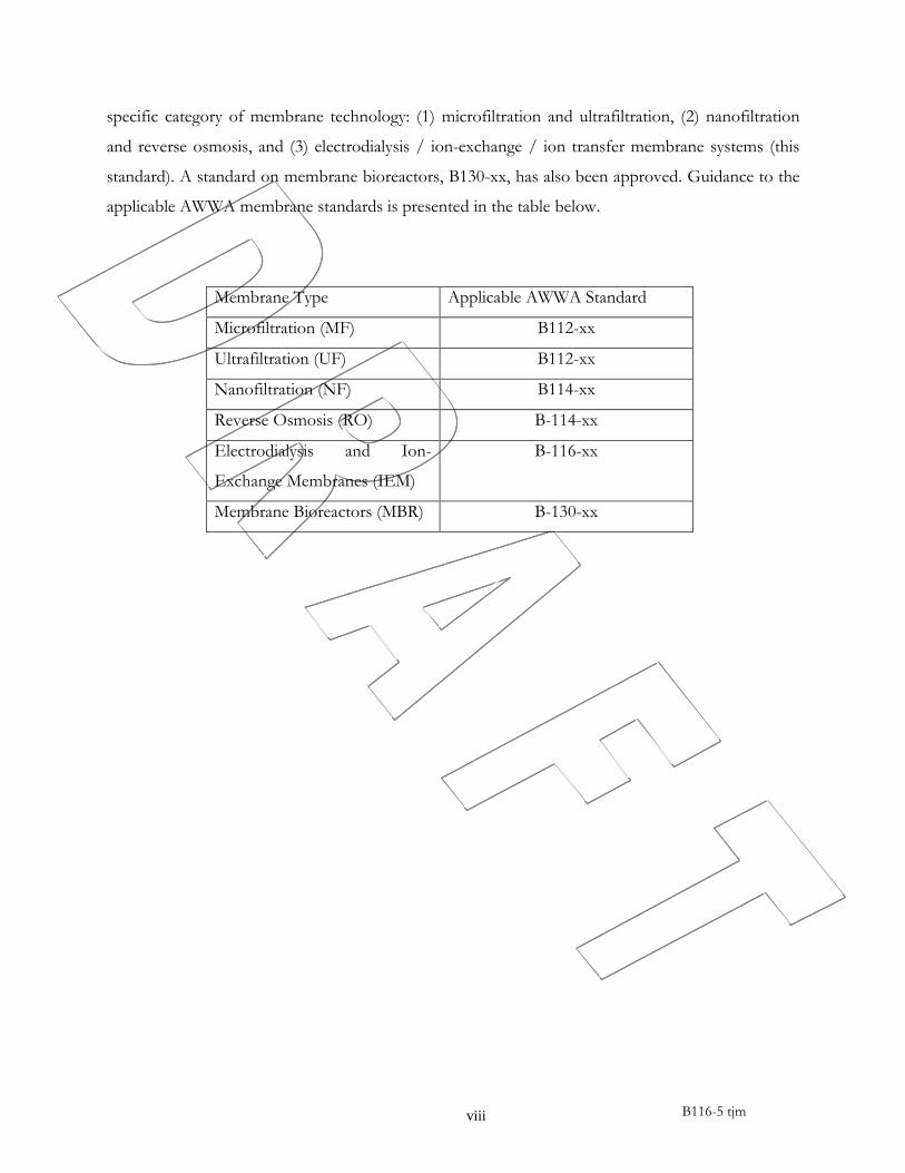
specific category of membrane technology: (1) microfiltration and ultrafiltration, (2) nanofiltration
and reverse osmosis, and (3) electrodialysis / ion-exchange / ion transfer membrane systems (this
standard). A standard on membrane bioreactors, B130-xx, has also been approved. Guidance to the
applicable AWWA membrane standards is presented in the table below.
Membrane Type Applicable AWWA Standard
Microfiltration (MF) B112-xx
Ultrafiltration (UF) B112-xx
Nanofiltration (NF) B114-xx
Reverse Osmosis (RO) B-114-xx
Electrodialysis and Ion-
Exchange Membranes (IEM)
B-116-xx
Membrane Bioreactors (MBR) B-130-xx
B116-5 tjm ix
I.C. Acceptance. In May 1985, the U.S. Environmental Protection Agency (USEPA) entered into a
cooperative agreement with a consortium led by NSF International* (NSF) to develop voluntary
third-party consensus standards and a certification program for direct and indirect drinking water
additives. Other members of the original consortium included the Water Research Foundation and
the Conference of State Health and Environmental Managers (COSHEM). The American Water
Works Association (AWWA) and the Association of State Drinking Water Administrators
(ASDWA) joined later.
In the United States, authority to regulate products for use in, or in contact with, drinking water
rests with individual states.† Local agencies may choose to impose requirements more stringent than
than those required by the state. To evaluate the health effects of products and drinking water
additives from such products, state and local agencies may use various references, including:
1. Specific policies of the state or local agency.
2. Two standards developed under the direction of NSF: NSF/ANSI‡ 60, Drinking Water
Treatment Chemicals—Health Effects, and NSF/ANSI 61, Drinking Water System Components—
Health Effects.
3. Other references, including AWWA standards, Food Chemicals Codex, Water Chemicals Codex,§
and other standards considered appropriate by the state or local agency.
Various certification organizations may be involved in certifying products in accordance with
NSF/ANSI 60 and 61. Individual states or local agencies have authority to accept or accredit
certification organizations within their jurisdiction. Accreditation of certification organizations may
vary from jurisdiction to jurisdiction.
II. Special Issues. There are no special issues related to this standard
III. Use of this Standard. It is the responsibility of the user of an AWWA standard to
determine that the products described in that standard are suitable for use in the particular
application being considered.
III.A. Purchaser Options and Alternatives. The following items should be covered by the
purchaser:
1. Standard used, that is, ANSI/AWWA B116-xx Electrodialysis and Ion-Exchange
* NSF International, 789 N. Dixboro Road, Ann Arbor, MI 48105. † Persons outside the United States should contact the appropriate authority having jurisdiction. ‡ American National Standards Institute, 25 West 43rd Street, Fourth Floor, New York, NY 10036.
§ Both publications available from National Academy of Sciences, 500 Fifth Street, NW, Washington, DC 2001.

B116-5 tjm x
Membrane Systems, of latest revision.
2. Details of other federal, state, local, and provincial requirements (Sec. 4.1).
3. Whether compliance with other standards, rules, or regulations in addition to the
requirements of the Safe Drinking Water Act are required (Sec. 4.6.4).
4. Whether plans, procedures, and required testing for permitting membrane systems shall be
required in the purchase documents. (Sec. 4.3.1.q)
5. Required number of training material packages (Sec. 5.3.1)
6. Performance test report requirments (Sec. 5.4.5)
III.B. Modification to standard. Any modification to the provisions, definitions, or terminology
in this standard must be provided by the purchaser.
IV. Major Revisions. This is the first edition of this standard.
V. Comments. If you have any comments or questions about this standard, please call the
AWWA Volunteer & Technical Support Group at 303.794.7711, FAX at 303.795.7603, write to the
group at 6666 West Quincy Avenue, Denver, CO 80235-3098, or e-mail the group at
1 B116-5 tjm
American Water Works Association
ANSI/AWWA B116-XX (First Edition)
AWWA STANDARD FOR
Electrodialysis and Ion-Exchange
Membrane Systems
SECTION 1: GENERAL
Sec. 1.1 Scope
This standard sets minimum requirements for ion-exchange membrane (IEM) systems such as
electrodialysis (ED), electrodialysis reversal (EDR), electrodialysis metathesis (EDM), and
electrodeionization (EDI) for water and reclaimed water treatment systems. Please note that the
terms ―ion exchange‖ and ―ion-exchange‖ are used interchangeably with the terms ―ion transfer‖
and ―ion-transfer‖ in this document. Characteristics of ED/EDR membranes are compared to other
types of membranes in Table 1.1.
Sec. 1.2 Purpose
The purpose of this standard is to provide a minimum set of requirements for ion-exchange
membrane systems used for water and reclaimed water treatment systems. This standard is intended
to assist with the design, procurement, installation, and commissioning of ion-exchange membrane
systems.
Sec. 1.3 Application
This standard can be referenced for design, procurement, installation, and commissioning of
ion-exchange membrane systems used for water and reclaimed water treatment systems.

2 B116-5 tjm
Table 1.1 Membrane characteristics by type *
Membrane Type Nominal Pore
Size (µm)
≥ 3-µm Particle or
Surrogate Organism
Removal
Virus (MS2 Phage)
Removal
Typical Molecular
Weight Cutoff
(Daltons)
Salt (NaCl)
Rejection
(%)***
Microfiltration (MF) 0.1 to 0.5 ≥99.9% (≥ 3 log) < 90% (< 1 log) ≥ 200,000 None
Ultrafiltration (UF) 0.005 to 0.1 ≥99.9% (≥ 3 log) ≥ 90% (≥ 1 log) 10,000 to 200,000 None
Nanofiltration (NF) ** and *** 0.001
(approximate
conceptual value)
Same as UF, but
typically not designed
for verifiable removal
Same as UF, but
typically not designed
for verifiable removal
~ 200 to > 500 0% to 95%
Reverse osmosis (RO) ** 0.001
(approximate
conceptual value)
Same as UF, but
typically not designed
for verifiable removal
Same as UF, but
typically not designed
for verifiable removal
< 200 to 500 . > 95%
Electrodialysis / Ion-Exchange
Membranes (IEM)
Not applicable Not applicable:
demineralized product
does not pass through a
membrane barrier
Not applicable:
demineralized product
does not pass through
a membrane barrier
Not applicable . > 45%
Abbreviations & Notes: Less than <; Greater than >; Greater than or equal to ≥; Approximately ~; micron µ
* The typical characteristics shown are considered applicable to this standard and its use.
** For NF and RO, rejection is generally based on test conditions for a single element, but there is some variation between membrane manufacturers and
membrane models. In general, test conditions tend to vary as follows: (1) feed solutions: 500 to 700 mg/L sodium chloride, magnesium chloride, calcium
chloride, or mixed solute solutions for NF; 1,500 to 2,000 mg/L sodium chloride for brackish water RO membranes; 32,000 to 38,000 mg/L sodium chloride
for seawater RO membranes; (1) 25oC temperature or corrected to that temperature; (3) 6 to 8 pH; (4) 8 to 20 percent recovery per element.
*** NF is similar to RO with the key difference being that NF has lower sodium chloride rejection than RO and NF exhibits greater selectivity in the types of
ions that are removed, such that NF allows a comparatively higher percentage of monovalent ions to pass to the permeate than multivalent ions.
3 B116-5 tjm
SECTION 2: REFERENCES
This standard references the following documents:
American Public Health Association (APHA), American Water Works Association
(AWWA), Water Environment Federation (WEF). Standard Methods for the
Examination of Water & Wastewater, 21st Edition (or later current Edition if available).
ASTM D5091, Standard Guide for Water Analysis for Electrodialysis/Electrodialysis
Reversal Applications.
ASTM D5131, Standard Guide for Record Keeping for Electrodialysis/Electrodialysis
Reversal Systems.
EPA 02/9203/EPADWCTR Protocol for Equipment Verification Testing for Removal of
Inorganic Constituents, April 2002
NSF/ANSI 60—Drinking Water Treatment Chemicals—Health Effects
NSF/ANSI 61—Drinking Water System Components—Health Effects
SECTION 3: DEFINITIONS
The following definitions shall apply in this standard:
Anion membrane (anion transfer or selective membrane): An ion-exchange membrane through which
anions transfer selectively over cations, generally related to ED systems.
Anode (positive electrode): The electrode that attracts anions (negatively charged ions), generally
related to ED systems.
Applied Pressure: For a membrane train, feed hydraulic pressure minus permeate and/or filtrate
hydraulic pressure.
Array: The overall arrangement of pressure vessels in a membrane system train, including the
groupings in parallel and series. For example, a 12:6 array has two stages with 12 vessels in
the first stage and 6 in the second stage.
Brackish water: Water with an approximate concentration of total dissolved solids (TDS) ranging
from 500 to 10,000 mg/L. Related terms: highly brackish water, seawater.
Brine: A concentrated salt solution. Although not preferred terminology per this standard, the
terms retentate, reject, and brine are sometimes used as equivalent to concentrate.
Cation membrane (cation transfer or selective membrane): An ion-exchange membrane through which
cations transfer selectively over anions, generally related to ED systems.
4 B116-5 tjm
Cell: The water-filled space between two ion-exchange membranes – either ―concentrate cell‖ or
―diluate cell‖.
Cell pair: Repetitive section of a membrane stack consisting of a cation membrane, a
demineralized water flow spacer, an anion membrane and a concentrate water flow spacer,
generally related to ED systems. A typical ED/EDR cell-pair contains one concentrate cell
and one diluate cell. EDM systems typically include repeating units of two distinct cell pairs
(four membranes and four spacers).
Chemical cleaning: An operation to clean the membrane material using chemical solution(s) and
typically having a duration longer than 60 minutes and less than 12 hours.
Chemical wash (CW): A short duration operation to clean the membrane material in place using
chemical solution(s) that has a total off-line duration of less than 60 minutes.
Chemically-enhanced backwash (CEB): Backwash with chemical addition with the time durations
defined for chemical wash. See maintenance wash.
Clean-in-place (CIP): A common type of membrane cleaning process using a chemical cleaning
system in which membrane elements are cleaned without moving them from their normal
service location.
Cleaning: An operation during which membrane is cleaned using a membrane cleaning system.
Concentrate: The stream exiting a membrane device, which has increased concentration(s) of
solute(s) and/or particle(s) compared to the feed stream. For drinking water applications,
concentrate is usually a waste stream. Although not preferred terminology per this standard,
the terms retentate, reject, and brine are sometimes used as equivalent to concentrate.
Conductivity: Measure of a substance’s ability to conduct an electrical current as measured by a
conductivity meter, which is the inverse of resistivity. Reported in Siemens per meter (S/m)
or, commonly, reported in micromhos or microSiemens per centimeter (µmhos/cm or
µS/cm), temperature corrected to 25° C.
Dalton: A unit of mass equal to 1/12th the mass of a carbon-12 atom or one atomic mass unit
(amu).
Desalination: A process for the removal of significant amounts of dissolved salts from a feed
water stream.
Desalinization: Although not preferred terminology per this standard, sometimes used as an
equivalent to desalination.
Desalting: The reduction of dissolved salts from water.

5 B116-5 tjm
Diluate: The product water from ED which has a reduced ionic content relative to the feed.
Electrical Stage: ED membranes mounted between one pair of positive and negative electrodes
and the pair of electrodes comprise one electrical stage.
Electrode: An electrically conductive material (typically metal or carbon) used to apply electrical
voltage and current to an ED stack.
Electrodeionization (EDI): A variant of ED in which diluate (and sometimes concentrate) solution
compartments are filled with ion-exchange material to reduce the resistance to current flow
and achieve improved salt removal. EDI systems are typically used for production of low-
conductivity water.
Electrodialysis (ED): A demineralization process in which ions are transferred through ion-
selective membranes by application of an electromotive force, voltage-driven direct electric
current, from a less concentrated solution to a more concentrated solution. Note: ED is not
a "membrane filtration" process, because the demineralized (product) water does not pass
through the membrane barrier. Related term: Electrodialysis reversal (EDR).
Electrodialysis Metathesis (EDM). A type of ED process which utilizes repeating units of two
distinct cell-pairs and four process streams (two concentrate streams and two diluate
streams). The two distinct cell-pairs may employ different types of anion or cation exchange
membranes (e.g., monovalent selective membranes). Related term: Electrodialysis (ED).
Electrodialysis reversal (EDR): A type of ED process in which the polarities of the electrodes are
periodically reversed to change the direction of ion movement for membrane scaling and
fouling control. Related term: Electrodialysis (ED).
Electrode Compartment: Water flow compartment containing the metal electrode where oxidation
or reduction occurs, generally related to ED, EDR, EDM, and EDI.
Filtrate: The portion of the feed stream that has passed through MF/UF membrane.
Feed channel spacer: A plastic material, often netting, between membrane leaves that provides the
flow channel for the fluid passing over the surface of the membrane that can increase the
turbulence of the feed-concentrate stream.
Fouling index: An index that indicates the potential for fouling within a membrane system.
Related term: Silt Density Index (SDI).
Highly brackish water: Water with an approximate concentration of dissolved solids ranging from
greater than 10,000 to 30,000 mg/L. Related terms: brackish water, seawater.
Hydrophilic: Having an affinity for water.

6 B116-5 tjm
Hydrophobic: Lacking an affinity for water.
Langelier saturation index (LSI): A calculated index indicating the tendency of a solution to dissolve
(negative value), precipitate (positive value), or be at equilibrium (value equal to zero) with
calcium carbonate. LSI = pHa - pHs where pHa is the actual solution pH and pHs is the pH if
the solution were at saturation with calcium carbonate. The value of pHs is calculated based
on the concentrations of calcium, alkalinity, and dissolved ions, and temperature.
Log Removal Value (LRV): A measure of the removal effectiveness of a parameter expressed as
the log 10 of the concentration in the feed minus the log 10 of the concentration in the
filtrate or product. For example, given a 10-fold reduction in a concentration, such as from
200 in the feed to 20 in the filtrate, the LRV equals 1.
Maintenance wash (MW): See chemically-enhanced backwash (CEB).
Manufacturer: The party that manufactures, fabricates, or produces materials or products.
Material Safety Data Sheet (MSDS): Sometimes referred to as Safety Data Sheet (SDS). Document
obtained or developed by chemical manufacturers and importers concerning each hazardous
chemical they produce or import describing information for safe transport, handling, and
use. Employers are required to have a material safety data sheet in the workplace for each
hazardous chemical used there. See Safety Data Sheet (SDS).
Membrane: An engineered material designed to remove solids (dissolved or suspended) that are
rejected from the system as either backwash or a concentrate stream, and produces a stream
containing less solute or particles (the product or filtrate stream). This standard focuses on
treatment processes that employ ion-exchange membranes, which selectively allow or restrict
ionic transport. Membrane types in pressure-driven standards include low-pressure
membranes such as microfiltration (MF) and ultrafiltration (UF), as well as higher-pressure
membranes such as nanofiltration (NF) and reverse osmosis (RO). Other definitions are
more restrictive including the Long Term 2 Enhanced Surface Water Treatment Rule
(LT2ESWTR), which defines membrane filtration as ―a pressure- or vacuum-driven
separation process in which particulate matter larger than 1 micron is rejected by a
nonfibrous engineered barrier‖.
Membrane cleaning system: Tanks, filtration devices, pumps and associated equipment and
appurtenances which are periodically used to prepare and feed chemical solutions to the
membrane element(s) to recover lost performance.
7 B116-5 tjm
Microfiltration (MF): Membrane filtration process with pore diameter nominally at least 0.1 micron
that provides at least 3 log removal of Giardia cysts or Cryptosporidium oocysts or similar-
sized, 3 micron and larger, surrogate materials based on challenge testing per USEPA
Membrane Filtration Guidance Manual.
Nanofiltration (NF): Membrane filtration process that removes dissolved constituents from water
- such as dissolved organics, color, calcium and magnesium (hardness) ions and other ions.
NF membrane elements provide a nominal organic molecular weight cutoff in the range of
about 200 to >500 Daltons and sodium chloride rejection of 0 to 95 percent. NF is similar
to RO with the key difference being that NF has lower sodium chloride rejection than RO
and it exhibits more selectivity in the types of ions that are removed such that NF allows a
comparatively higher percentage of monovalent ions to pass to the permeate than
multivalent ions.
Net production rate: The actual product flow rate minus any in-plant water use that does not
contribute to usable product, such as for backwash or other operations, and taking into
account downtime for operations that do not yield product, such as backwashing and
integrity testing. Units of measurement are commonly gallons per day (gpd) or cubic meters
per day (m3/d).
Pass: A membrane treatment step in which a feed stream, or a portion of a feed stream, is
converted to a product stream. For example, in a one-pass system, the feed stream is treated
in a single membrane treatment step. In a two-pass system, some or all of the product from
the first pass becomes feed to a second membrane treatment step.
Plate and frame: A configuration containing flat sheets of membranes separated by alternating
product or filtrate spacers and feed/concentrate spacers, held in place by a structure,
typically associated with ED systems, but can be applied to other types of membrane
processes.
Post-treatment: Any treatment applied to the filtrate, permeate, or product of a membrane process,
generally applied to achieve finished water quality objectives.
Potable water: Water that is safe and satisfactory for drinking and cooking.
Pressure-driven: Type of system applying force obtained from a pump or other source (such as
taking advantage of available pressure or hydraulic elevation differentials across the system)
that provides positive hydraulic pressure to a feed stream that permits a type of membrane
system to operate.

8 B116-5 tjm
Pretreatment: Any treatment applied to the feed water of a membrane process, generally to achieve
desired water quality objectives and/or protect the membrane from damage or fouling.
Product: For MF or UF, see filtrate. For RO, NF, and ED, the portion of the separated feed
stream that has reduced constituent concentrations. For ED, also see diluate.
Purchaser: The person, company, or organization that purchases any materials or work to be
performed.
Reclaimed water: Wastewater that becomes suitable for beneficial use as a result of treatment.
Recovery: For RO/NF/ED, the ratio of product flow to feed flow. For MF/UF, the ratio of net
filtrate production to feed flow supplied to the membrane system over a defined time period.
Recovery is expressed as a percent.
Reverse Osmosis (RO): Membrane filtration and desalination process that removes dissolved
constituents from water including dissolved organics, color, DBP-precursors, hardness, and
other dissolved ions, and/or total dissolved solids (TDS). RO membrane elements have a
nominal organic molecular weight cutoff in the range of 200 to 500 Daltons and sodium
chloride rejection greater than 95 percent.
Safety Data Sheet (SDS): See Material Safety Data Sheet (MSDS)
Seawater: Ocean water with an approximate concentration of total dissolved solids ranging from
greater than 30,000 mg/L to about 50,000 mg/L. Related terms: brackish water, highly brackish
water.
Silt Density Index (SDI): Silt density index is an indication of the amount of particulate matter in
water, a type of fouling index. SDI indicates the rate of plugging of 0.45 µm membrane filter
as a dimensionless index value as described in ASTM test method 4189-07 ―Standard Test
Method for Silt Density Index (SDI) of Water.‖ SDI15 is the most commonly used value
which is determined by using a 15 minute filtration duration.
Spiral wound: A configuration in which flat sheets of a semi-permeable membrane, a porous
support matrix, and a spacer are wrapped around a central filtrate/permeate collector tube;
typically associated with NF and RO but can be applied to other types such as EDI.
Stage: A group of membrane vessels or stacks plumbed in parallel with common feed and
concentrate manifolds. For example, in a two-stage system the concentrate from the first
stage becomes the feed to the second stage. The term ―stage‖ is assumed to refer to a
hydraulic stage, unless the phrase ―electrical stage‖ is used.
9 B116-5 tjm
Stiff-and Davis Stability Index (S&DSI): A calculated index, generally applicable to waters with total
dissolved solids (TDS) concentration greater than 10,000 mg/L, indicating the tendency of a
solution to dissolve (negative value), precipitate (positive value), or be at equilibrium (value
equal to zero) with calcium carbonate. S&DSI = pHa - pHs where pHa is the actual solution
pH and pHs is the pH if the solution were at saturation with calcium carbonate. The value of
pHs is calculated based on the concentrations of calcium, alkalinity, as well as a specified
constant that is dependent on ionic strength and temperature.
Supplier: The party who supplies material or services. A supplier may or may not be the
manufacturer.
Temperature-corrected: Value, such as flux or driving pressure, corrected from ambient temperature
to a reference temperature – for MF/UF the reference temperature is commonly 20 °C and
for RO/NF/ED the reference temperature is commonly 25 °C.
Total Dissolved Solids (TDS): Residual material remaining after filtering suspended material from a
solution through a standard glass fiber filter and evaporating the filtrate to a dry state at
180°C. Specific methods for determination given in appropriate section of Standard Methods
for the Examination of Water & Wastewater, 21st Edition, Method 2540 C, or similar method in later
Editions. Usually expressed as mg/L.
Train: A group of membrane vessels or stacks functioning as one unit with common inlet and
outlet connections, complete with common monitoring and control equipment. Often a
membrane treatment facility has multiple parallel trains. A train can be operated
independently from other trains and can be isolated from the rest of the system.
Ultrafiltration (UF): Membrane filtration process with pore diameter nominally in the range of
0.005 to 0.1 micron with a nominal organic molecular weight cutoff in the range of 10,000 to
300,000 Daltons that provides at least 1 log removal of virus, MS2 phage, in challenge testing
per USEPA Membrane Filtration Guidance Manual as well as providing the log removal
defined for MF.
Waste neutralization system: Tanks, devices, pumps, associated equipment, and appurtenances
which are periodically used to prepare and feed chemical solutions to the waste streams from
membrane cleaning, backwashing, or other operations system before the waste is discharged.
Water flow spacer: Material which forms a flow path for a stream within an element, stack, or
module.
10 B116-5 tjm
SECTION 4: REQUIREMENTS
Sec. 4.1 Materials
Materials shall comply with the requirements of the Safe Drinking Water Act, other federal
regulations for water and reclaimed water systems, and other regulatory agency rules, as applicable.
Sec. 4.2 System Requirements
4.2.1 Required equipment. Membrane systems shall include:
a) Membrane stacks/modules.
b) Support devices such as a frame weldment for membranes, piping, and panels.
c) Piping, tubing, valves and fittings on the membrane unit.
d) Process stream feed pumps.
e) Concentrate pumps and degasifier blowers as required per membrane system supplier.
f) Programmable logic computers (PLCs), software, and programming, and membrane
cleaning system.
g) DC Power Supply System.
4.2.2 Excluded systems and facilities. Membrane systems per this standard do not include the
following systems and facilities:
a) Source water supply.
b) Membrane pretreatment, such as for turbidity, TOC, and/or H2S removal.
c) Concentrate, spent membrane cleaning, waste neutralization handling, and disposal
facilities.
d) Chemical storage and feed systems.
e) Interconnecting piping, electrical and control wiring and conduits.
f) Facility where membrane system is housed.
g) Regulatory agency permits.
Sec. 4.3 Data to be Provided by System Supplier
4.3.1 Data provided by the supplier with proposal. The supplier of the membrane system shall
provide the following information:
a. Complete System Description Table (See Appendix B).

11 B116-5 tjm
b. Ion removal as a function of water temperature and net flow capacity with one or more
trains out of service as specified by the purchaser and/or as proposed by supplier.
c. Preliminary process flow diagram and flow balance.
d. Preliminary instrumentation and control diagrams (P&IDs).
e. Preliminary layout drawing(s).
f. Preliminary electrical one-line diagram.
g. List of major materials of construction including skid materials, piping, and elastomers.
h. List of cleaning procedures.
i. List of pretreated feed water quality requirements.
j. Statements indicating membrane system materials are compatible with other systems to be
used in the process including pretreatment or other process chemicals.
k. List of spare parts, special tools, and special services, including startup and installation, that
will be provided with the system.
l. List of proposed chemicals for use as membrane preservative and method(s) of disposal.
m. List of proposed chemicals and quantities for startup, operations, and maintenance activities.
n. Services and equipment to be provided by others, including if applicable, services such as
onsite erection and installation of membrane equipment.
o. Predicted filtrate, permeate or product quality based on source water quality and key
operating parameters.
p. Computer projections estimating hydraulic and water quality performance at startup and
after 5 years of operations, including projected operating pressures of the system,
concentrate stream scaling parameters for calcium carbonate, calcium sulfate, barium sulfate,
strontium sulfate, and Langelier Saturation Index (LSI) and/or Stiff & Davis Stability Index
(S&DSI)
q. Plans, procedures, and required testing for permitting membrane system shall be provided
when required in the purchase documents.
4.3.2 Data required prior to manufacturing. The supplier of the membrane system shall provide
the following information prior to manufacturing the system:
a. Revised process flow diagram and flow balance table for major streams.
b. Completed Process and Instrumentation Diagrams (P&IDs) including information about
equipment, piping, instrumentation, and control and other types of valves as well as showing
chemical injection locations.

12 B116-5 tjm
c. Description of the control system and Programmable Logic Controllers (PLCs) software,
and how the membrane system will be integrated into overall water plant control system.
d. Revised layout drawing(s) showing how the equipment will fit into the building or other
structure which will house the system and location of anchor bolts and equipment supports.
e. Electrical one-line diagram and termination drawings, indicating all internal and external
electrical connections.
f. Product data sheets and tables describing major equipment items. These shall be clearly
marked and annotated to show the applicable model numbers, ratings, and features.
1) Major equipment shall include: cartridge filters, pumps and motors, DC power supply,
membrane stacks/modules, tanks, heaters, control valves, if applicable, equipment
support/anchorage details, and instruments, as applicable.
2) Details on pumps shall include: manufacturer, model number, impeller size, pump
curves, efficiency, materials of construction, seal type and manufacturer, motor data
including: manufacturer, model, type, rated size in horsepower or kilowatts, and service
factor.
3) Membranes and stack detail drawings.
4) Computer-generated printouts of projected performance.
5) Details on control valves shall include manufacturer, model number, pressure class,
materials of construction, and table or figure to show flow coefficient (Cv) as a function
of percent open.
g. Piping schedule listing service, pipe code, diameter, pressure class and materials of
construction.
h. Valve schedule listing tag number, manufacturer, model number, size, type, pressure class
and materials of construction for all valves, including vacuum breakers and check valves.
i. Instrumentation/device schedule listing tag number, manufacturer, model number,
measured parameter, and ranges for instruments and devices (e.g., pH, conductivity,
temperature sensors).
j. Control philosophy (process control narratives).
k. Chemical dosing system and purpose.
l. Functional testing plans.
m. Startup and commissioning plans with operational and maintenance forms and/or checklists.
n. Updated plans, procedures, and required testing for permitting membrane system shall be

13 B116-5 tjm
provided when required in the purchase documents.
4.3.3 Data provided prior to start-up. The supplier of the membrane system shall provide the
following information prior to start-up of the system:
a. Revised versions of the documents and drawings listed in the previous subsection.
b. Operation and Maintenance (O&M) Manuals for the membrane system and appurtenances.
These O&M Manuals shall describe the system components, membrane feed water
characteristics including ranges thereof, system and component specifications, standard
operating procedures, limitations including conditions to be avoided or that could damage
the equipment, and operation and maintenance procedures. Data tables shall be included to
show typical operating set points and conditions. O&M Manuals shall also include printouts
of the programming logic, printouts of the control and data screens, an electronic copy of
the control logic in case of emergency and a list of all information exchanged with the plant
control system, including data table addresses.
c. Documentation required for permitting the membrane system as per request of the
purchaser.
4.3.4 Record drawings. After start-up of the system, the supplier of the membrane system shall
provide a complete set of the documents (including drawings) listed in the previous subsections,
revised to show system ―as installed‖.
Sec. 4.4 Water Flow and Water Quality Data Requirements
The membrane system shall meet the performance criteria based on the project’s water flow and
water quality data requirements. The following items shall be provided by the purchaser.
4.4.1 Flow rate. Feed flow rate, in gpm, gpd, or acre-foot/year (m3/d, m3/h, or m3/year), or
an alternative approach whereby production rate and minimum recovery are provided.
4.4.2 Recovery. Minimum, maximum, and design target recovery, in percentage.
4.4.3 Design temperature. Design temperature and temperature range, in oF (oC), as a function
of flow rate.
4.4.4 Source. The source(s) of feedwater shall be documented.
4.4.5 Upstream treatment. Description of treatment processes upstream from the membrane
process, including recirculation of streams to points upstream from the membrane process.
4.4.6 Water quality. The raw or feed water quality data provided for design shall be as shown
in Table 4.1. The table identifies required items with ―R‖ and optional items ―O‖. It is
14 B116-5 tjm
recommended that feed water quality variation and temperature be documented and used in the
system design. For each item it is recommended that values be presented for minimum, maximum,
and average or typical, if available. Alternatively, values may be presented for 10 percent, 95 percent,
and 50 percentiles (or mean or median).

15 B116-5 tjm
Table 4.1 Raw and/or feed water quality data to be provided
Parameter (units) Req./Opt.
Temperature (oF or oC) R
Turbidity (NTU) R
SDI15 (dimensionless) O
SDI5 (dimensionless) O
pH (standard pH units) R
Total Organic Carbon (TOC) O
Dissolved Organic Carbon (DOC) O
Ultraviolet Light UV-254 (m-1) O
Color, True and Apparent (Color Units) O
Iron, Total (mg/L) R
Iron, Dissolved (mg/L) O
Manganese, Total (mg/L) R
Manganese, Dissolved (mg/L) O
Alkalinity (mg/L as CaCO3) or Carbonate and Bicarbonate R
Total Hardness (mg/L as CaCO3) R
Oil and Grease (mg/L) O
Biochemical Oxygen Demand (BOD) O
Chemical Oxygen Demand (COD) O
Total Suspended Solids (TSS) O
Total Dissolved Solids (TDS) or Conductivity (µS/cm) R
Microbiological parameters, such as algae, Total Coliform, Fecal Coliform, and Heterotrophic Place Count, in standard units
O
Calcium (mg/L) R
Magnesium (mg/L) R
Sodium (mg/L) R
Potassium (mg/L) O
Barium (mg/L) R
Strontium (mg/L) R
Ammonia (mg/L) O
Aluminum (mg/L) R
Sulfate (mg/L) R
Chloride (mg/L) R
Fluoride (mg/L) R
Nitrate (mg/L) R
Nitrite (mg/L) O
Boron (mg/L) O
Bromide (mg/L) O
Phosphate (mg/L) O
Arsenic (mg/L) O
Silica (mg/L as SiO2) O
H2S (if present) R
Dissolved Oxygen (mg/L) O
16 B116-5 tjm
Sec. 4.5 Performance Criteria
4.5.1 Performance criteria. Membrane systems shall be designed to meet the following
performance criteria when treating membrane system feed water and associated seasonal variations.
These criteria shall be clearly defined by the supplier including:
4.5.1.1 Production rate. Net production rate per day at a required design temperature or
range of temperatures including all waste flows from system (electrode, concentrate, off-spec
product)
4.5.1.2 Water quality. Product water quality shall meet the following requirements:
a. Total dissolved solids (TDS) or conductivity with any specific constituent limits; specific
solute, TDS, or conductivity passage or rejection, expressed in percent.
b. Required water quality parameters, including each of the measurement values,
measurement techniques and test conditions.
4.5.1.3 Recovery. Minimum, maximum, and design target recovery.
4.5.1.4 pH. Minimum, maximum, and design target feed pH.
4.5.1.5 Temperature. Minimum, maximum, and average water temperature.
4.5.1.6 Pressure. Pressure criteria requirements including:
a. Maximum allowable feed stream hydraulic operating pressure at a specified temperature
and time period at the planned system product pressure.
b. Maximum allowable hydraulic pressure drop, across the entire system and/or stacks.
c. Maximum allowable pressure in the product stream plumbing.
d. Maximum allowed differential pressure between dilute and concentrate streams.
e. Maximum allowable inlet pressure at unit and at module or stack.
4.5.1.7 Concentrate. Concentrate stream quality and quantity recognizing that feed,
product, and recovery parameters will influence the resulting concentrate parameters.
4.5.1.8 Key operating parameters. Key operation and maintenance schedules and
parameters shall be documented as part of system performance testing.
4.5.1.9 Clean-in-Place (CIP). The maximum and minimum frequency or performance
triggers for each type of cleaning, including chemical concentrations and exposure limits, and
temperature requirements for membrane and spacer clean-in-place activities (including chemical
wash, CEB/MW, chemical cleaning, and CIP cycles).
4.5.1.10 Electrode Clean-in-Place (ECIP). The maximum and minimum frequency or
duration, chemical concentrations and exposure limits, and temperature requirements for
17 B116-5 tjm
electrode clean-in-place activities (chemical wash, chemical cleaning).
4.5.1.11 Other conditions. Any other conditions for ECIP, CIP, such as chemical used,
concentration and limits to protect the membrane.
4.5.1.12 EDR Reversal Operation times. Duration of operation between polarity reversals.
4.5.1.13 Shutdown flush. Flush procedures and flush water source used if needed to protect
the membrane system upon shutdown.
4.5.1.14 Membrane storage solutions. Short and long term membrane preservative/storage
solutions and protocols.
Sec. 4.6 Products/Components
4.6.1 Materials of construction. The products and components of a membrane system shall be
constructed of materials that are resistant to corrosion in the environment in which they are placed.
Metals, fiberglass, and plastics are acceptable materials of construction, provided they can withstand
the rigors of their internal and external environments.
4.6.2 Pressure ratings. The materials of construction must be suitable for pressures in excess of
the greatest possible pressure each component may be exposed to after installation.
4.6.3 Temperature variations. Membrane systems may operate under temperature conditions other
than ambient. Materials in such use must be structurally sound over these temperature variations at
maximum operating pressures.
4.6.4 Toxicity levels. Products and components must not leach toxic substances into the water
that is distributed to the public or the environment in their intended use. Disposal methods for
residuals and used components that meet applicable regulatory requirements shall be available.
Evaluation shall be accomplished in accordance with requirements that are no less restrictive than
those listed in NSF/ANSI 60 or NSF/ANSI 61, respectively, if required by applicable regulatory
agency and/or specified by the purchaser. Certification shall be accomplished by a certification
organization accredited by the American National Standards Institute.
4.6.4.1 NSF/ANSI 60. Chemicals used in membrane systems shall, if required by
applicable regulatory agency and/or specified by the purchaser, be certified as suitable for
contact with, or treatment of, drinking water by an accredited certification organization in
accordance with NSF/ANSI 60.
4.6.4.2 NSF/ANSI 61. Components used in membrane systems shall, if required by
applicable regulatory agency and/or by the purchaser, be certified as suitable for contact with, or
18 B116-5 tjm
treatment of, drinking water by an accredited certification organization in accordance with
NSF/ANSI 61.
4.6.5 Safety considerations. Products and components must be safe to use. Protection to
personnel, equipment, and the environment must be assured through the proper installation and use
of safety devices, such as pressure relief valves and/or rupture disks.
4.6.6 Components. Products/components are composed of the following items
4.6.6.1 Membranes. Configuration can be flat sheet, plate and frame, or spiral-wound.
4.6.6.2 ED stacks are restrained by end blocks, usually plastic, on the top and bottom of
the stack with end plates and tie rods, usually steel, enclosed in removable covers, usually plastic.
A stack is comprised of multiple cell pairs, which are anion and cation transfer membranes and
intermediate flow spacers. The exact number of cell pairs is dependant on site-specific
requirements. Electrode and electrode flow spacer are located at the top and bottom of a group
of membrane cell pairs in stacks.
4.6.6.3 Pumps. Materials of construction shall be suitable for service environment.
4.6.6.4 Cleaning. Clean-in-place systems are applied to clean one train at a time (or
portion of a train, if sufficient valves and piping provided) with the element(s) left in their
normal operating location at almost all full-scale plants. For some small facilities, elements may
be cleaned in place or moved to another location for cleaning.
4.6.6.5 Chemicals. Routine and/or continuous additions may be required for acid, base,
biocide, and/or antiscalant chemicals. Cleaning agents may include acids, bases, detergents,
disinfectants, biocides, and/or proprietary formulations as appropriate for the specific
membrane and system.
4.6.6.6 Piping. Materials of construction are generally plastics suitable for service
environment. Manifolds are provided to uniformly split the feed water.
4.6.6.7 Valves. Materials of construction shall be suitable for the service environment. All
types of configurations are possible – isolation, control, regulators, flow check, relief, and other
types.
4.6.6.8 Supports. Racks are usually metallic or FRP and shall be designed for loads
assuming pressure vessels and piping contain water. Supports shall be painted/coated for
corrosion protection or made of stainless steel.
4.6.6.9 Instrumentation and control. Recorders and controllers shall be provided with
feedback or feed forward loops. Data shall be sent to a programmable logic controller (PLC)

19 B116-5 tjm
where data is received and analyzed. Supervisory control and data acquisition (SCADA) system
shall be provided. Key variables shall be monitored including flows, pressures, temperatures,
pressure drops, water conductivities/compositions. Alarms and shutdown switches shall be
provided on key variables including safety measures and quality control.
4.6.6.10 Air compressors and/or blowers. Some systems require air compressors and/or
blowers. Sufficient capacity, pressure relief, hydraulic design, and level of air quality (considering
level of particle filtering, dryness, and acceptable oil concentration, if any) should be appropriate
for process and service requirements as defined by membrane system supplier. Degasification
system(s) and equipment shall be provided as needed to remove and safely dispose of reaction
gases.
4.6.6.11 Sample taps shall be provided to evaluate water quality of the major process
streams, such as feed, product, concentrate, recycle and waste streams.
4.6.6.12 Systems shall be provided that send data to control room or local panel board.
4.6.6.13 General components, as applicable: Provide lifting lugs, anchor bolts, support
structure pressure vessel straps for restricting movement, identification labels and numbering on
equipment, color and tagging identification of electrical wiring and piping with directional
markings, instrumentation test or calibration equipment, stack probing equipment, flexible hoses
and restraints.
4.6.7. Miscellaneous Items
4.6.7.1 Spare parts. Spare parts, such as membrane modules, spacers, electrode, stacks,
pumps, valves, piping, and so on shall be provided as specified by the purchaser and/or
otherwise provided by supplier.
4.6.7.2 Installation instructions. Detailed installation instructions for all equipment shall
be provided prior to equipment installation.
4.6.7.3 Operation and Maintenance (O&M) Manuals. O&M Manuals shall include the
following: operating instructions including start-up, routine and normal operation; data tables
showing typical operating setpoints and conditions; printouts of the control and data screen;
regulation and control descriptions; shutdown and emergency conditions; maintenance
instructions and recommended frequencies; equipment specifications; raw material
specifications; cost records for control; appropriate shift log books and/or control data sheets /
spreadsheets with instructions for all tests, forms, and/or checklists; safety manual(s); and
emergency shut-down/evacuation procedures.
20 B116-5 tjm
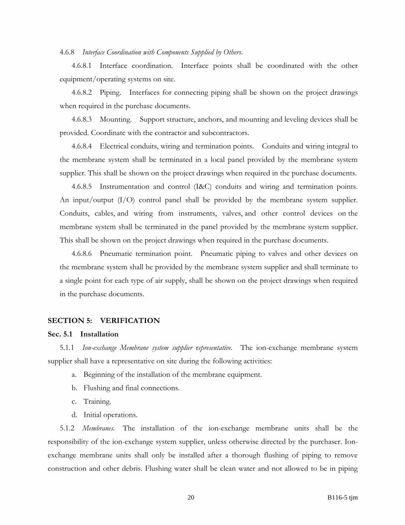
4.6.8 Interface Coordination with Components Supplied by Others.
4.6.8.1 Interface coordination. Interface points shall be coordinated with the other
equipment/operating systems on site.
4.6.8.2 Piping. Interfaces for connecting piping shall be shown on the project drawings
when required in the purchase documents.
4.6.8.3 Mounting. Support structure, anchors, and mounting and leveling devices shall be
provided. Coordinate with the contractor and subcontractors.
4.6.8.4 Electrical conduits, wiring and termination points. Conduits and wiring integral to
the membrane system shall be terminated in a local panel provided by the membrane system
supplier. This shall be shown on the project drawings when required in the purchase documents.
4.6.8.5 Instrumentation and control (I&C) conduits and wiring and termination points.
An input/output (I/O) control panel shall be provided by the membrane system supplier.
Conduits, cables, and wiring from instruments, valves, and other control devices on the
membrane system shall be terminated in the panel provided by the membrane system supplier.
This shall be shown on the project drawings when required in the purchase documents.
4.6.8.6 Pneumatic termination point. Pneumatic piping to valves and other devices on
the membrane system shall be provided by the membrane system supplier and shall terminate to
a single point for each type of air supply, shall be shown on the project drawings when required
in the purchase documents.
SECTION 5: VERIFICATION
Sec. 5.1 Installation
5.1.1 Ion-exchange Membrane system supplier representative. The ion-exchange membrane system
supplier shall have a representative on site during the following activities:
a. Beginning of the installation of the membrane equipment.
b. Flushing and final connections.
c. Training.
d. Initial operations.
5.1.2 Membranes. The installation of the ion-exchange membrane units shall be the
responsibility of the ion-exchange system supplier, unless otherwise directed by the purchaser. Ion-
exchange membrane units shall only be installed after a thorough flushing of piping to remove
construction and other debris. Flushing water shall be clean water and not allowed to be in piping
21 B116-5 tjm
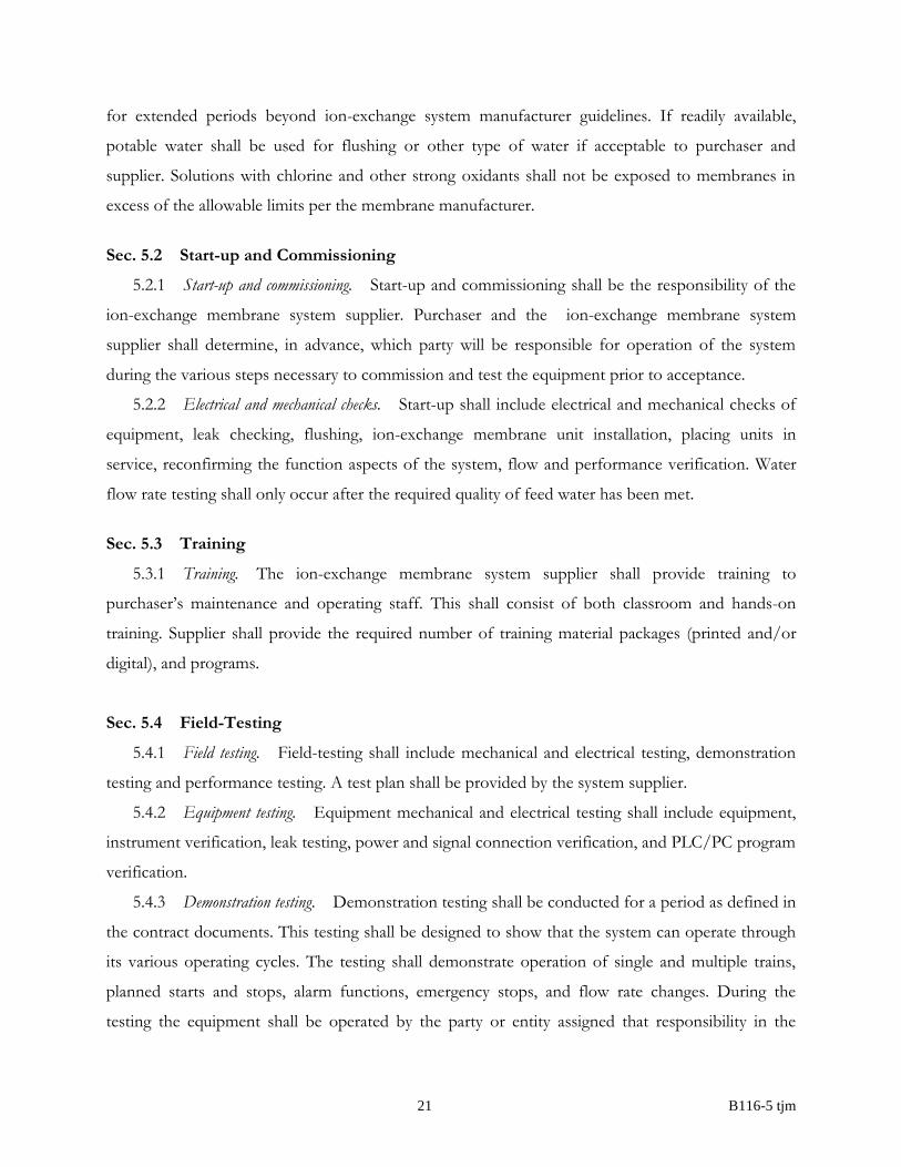
for extended periods beyond ion-exchange system manufacturer guidelines. If readily available,
potable water shall be used for flushing or other type of water if acceptable to purchaser and
supplier. Solutions with chlorine and other strong oxidants shall not be exposed to membranes in
excess of the allowable limits per the membrane manufacturer.
Sec. 5.2 Start-up and Commissioning
5.2.1 Start-up and commissioning. Start-up and commissioning shall be the responsibility of the
ion-exchange membrane system supplier. Purchaser and the ion-exchange membrane system
supplier shall determine, in advance, which party will be responsible for operation of the system
during the various steps necessary to commission and test the equipment prior to acceptance.
5.2.2 Electrical and mechanical checks. Start-up shall include electrical and mechanical checks of
equipment, leak checking, flushing, ion-exchange membrane unit installation, placing units in
service, reconfirming the function aspects of the system, flow and performance verification. Water
flow rate testing shall only occur after the required quality of feed water has been met.
Sec. 5.3 Training
5.3.1 Training. The ion-exchange membrane system supplier shall provide training to
purchaser’s maintenance and operating staff. This shall consist of both classroom and hands-on
training. Supplier shall provide the required number of training material packages (printed and/or
digital), and programs.
Sec. 5.4 Field-Testing
5.4.1 Field testing. Field-testing shall include mechanical and electrical testing, demonstration
testing and performance testing. A test plan shall be provided by the system supplier.
5.4.2 Equipment testing. Equipment mechanical and electrical testing shall include equipment,
instrument verification, leak testing, power and signal connection verification, and PLC/PC program
verification.
5.4.3 Demonstration testing. Demonstration testing shall be conducted for a period as defined in
the contract documents. This testing shall be designed to show that the system can operate through
its various operating cycles. The testing shall demonstrate operation of single and multiple trains,
planned starts and stops, alarm functions, emergency stops, and flow rate changes. During the
testing the equipment shall be operated by the party or entity assigned that responsibility in the

22 B116-5 tjm
contract documents. If a failure occurs the system supplier shall have no more than the period
defined in the contract documents to make adjustments.
5.4.4 Performance testing. Performance testing shall commence at the end of the demonstration
testing. The system shall meet the performance test requirements for a continuous period or a
portion of a period as required in the contract documents. Scheduling of the performance test is at
the purchaser’s discretion but shall occur after the completion of the demonstration test. The
performance test shall verify that the performance of the system can be met over an extended period
of time.
5.4.5 Performance test report. Upon completion of the test a report shall be prepared in
accordance with the contract documents. Purchaser shall determine whether the system
performance meets the contract requirements. Should the system fail to meet the requirements, the
system supplier shall make necessary corrections to the system and the test shall be repeated.
SECTION 6: DELIVERY
Sec. 6.1 Packaging
Equipment, spare parts, special tools and other items provided shall be properly marked and
packaged for protection during shipping, handling, and storage.
Sec. 6.2 Shipping, Handling and Storage
6.2.1 Deliveries. Deliveries shall be properly sequenced to have needed items on site and on
time so that construction and installation schedule is not negatively affected. Deliveries shall be
coordinated with the contractor, subcontractors, and the purchaser.
6.2.2 Manufacturer recommendations. Items shall be handled and stored as recommended by the
manufacturer.
6.2.3 Storage. Membranes shall be kept clean, in the recommended storage solution, at the
required environmental temperature range, and shall not be removed from shipping package
materials until time of installation.
6.2.4 MSDS. Supplier shall provide MSDS, SDS and/or other required forms of disclosure
regarding the preservative solution, if any, and shall provide recommended disposal practices.
23 B116-5 tjm
Sec. 6.3 Notice of Nonconformance
Any membrane system not conforming to the requirements of this standard shall be made
satisfactory or replaced by the supplier. The purchaser must provide a notice of nonconformance to
the supplier that explains the reason for nonconformance.
Sec. 6.4 Affidavit of Compliance
The purchaser may require an affidavit from the supplier that the material provided complies
with applicable requirements of this standard.
24 B116-5 tjm
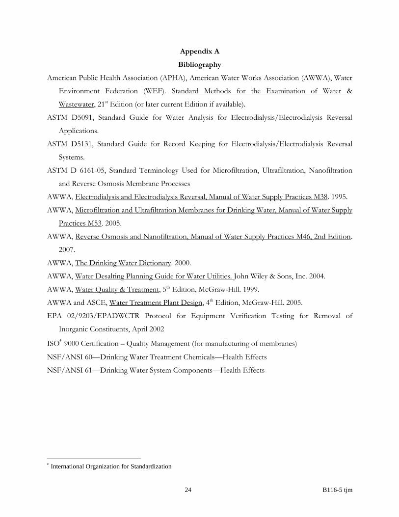
Appendix A
Bibliography
American Public Health Association (APHA), American Water Works Association (AWWA), Water
Environment Federation (WEF). Standard Methods for the Examination of Water &
Wastewater, 21st Edition (or later current Edition if available).
ASTM D5091, Standard Guide for Water Analysis for Electrodialysis/Electrodialysis Reversal
Applications.
ASTM D5131, Standard Guide for Record Keeping for Electrodialysis/Electrodialysis Reversal
Systems.
ASTM D 6161-05, Standard Terminology Used for Microfiltration, Ultrafiltration, Nanofiltration
and Reverse Osmosis Membrane Processes
AWWA, Electrodialysis and Electrodialysis Reversal, Manual of Water Supply Practices M38. 1995.
AWWA, Microfiltration and Ultrafiltration Membranes for Drinking Water, Manual of Water Supply
Practices M53. 2005.
AWWA, Reverse Osmosis and Nanofiltration, Manual of Water Supply Practices M46, 2nd Edition.
2007.
AWWA, The Drinking Water Dictionary. 2000.
AWWA, Water Desalting Planning Guide for Water Utilities. John Wiley & Sons, Inc. 2004.
AWWA, Water Quality & Treatment, 5th Edition, McGraw-Hill. 1999.
AWWA and ASCE, Water Treatment Plant Design, 4th Edition, McGraw-Hill. 2005.
EPA 02/9203/EPADWCTR Protocol for Equipment Verification Testing for Removal of
Inorganic Constituents, April 2002
ISO 9000 Certification – Quality Management (for manufacturing of membranes)
NSF/ANSI 60—Drinking Water Treatment Chemicals—Health Effects
NSF/ANSI 61—Drinking Water System Components—Health Effects
International Organization for Standardization
25 B116-5 tjm
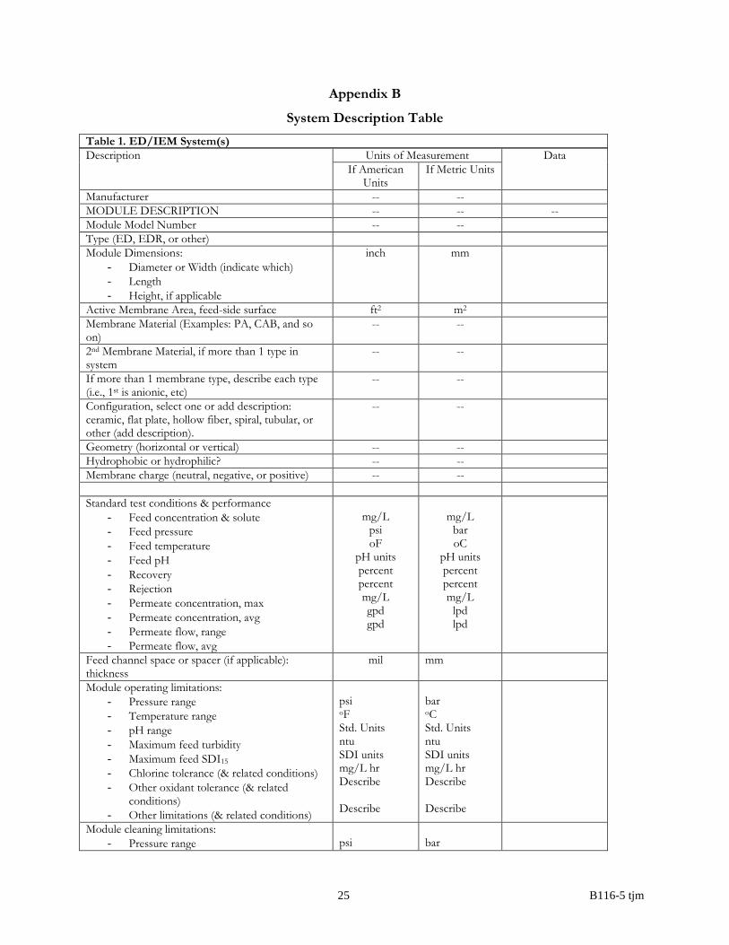
Appendix B
System Description Table
Table 1. ED/IEM System(s)
Description Units of Measurement Data
If American Units
If Metric Units
Manufacturer -- --
MODULE DESCRIPTION -- -- --
Module Model Number -- --
Type (ED, EDR, or other)
Module Dimensions:
- Diameter or Width (indicate which)
- Length
- Height, if applicable
inch mm
Active Membrane Area, feed-side surface ft2 m2
Membrane Material (Examples: PA, CAB, and so on)
-- --
2nd Membrane Material, if more than 1 type in system
-- --
If more than 1 membrane type, describe each type (i.e., 1st is anionic, etc)
-- --
Configuration, select one or add description: ceramic, flat plate, hollow fiber, spiral, tubular, or other (add description).
-- --
Geometry (horizontal or vertical) -- --
Hydrophobic or hydrophilic? -- --
Membrane charge (neutral, negative, or positive) -- --
Standard test conditions & performance
- Feed concentration & solute
- Feed pressure
- Feed temperature
- Feed pH
- Recovery
- Rejection
- Permeate concentration, max
- Permeate concentration, avg
- Permeate flow, range
- Permeate flow, avg
mg/L
psi oF
pH units percent percent mg/L gpd gpd
mg/L
bar oC
pH units percent percent mg/L
lpd lpd
Feed channel space or spacer (if applicable): thickness
mil mm
Module operating limitations:
- Pressure range
- Temperature range
- pH range
- Maximum feed turbidity
- Maximum feed SDI15
- Chlorine tolerance (& related conditions)
- Other oxidant tolerance (& related conditions)
- Other limitations (& related conditions)
psi oF Std. Units ntu SDI units mg/L hr Describe Describe
bar oC Std. Units ntu SDI units mg/L hr Describe Describe
Module cleaning limitations:
- Pressure range
psi
bar
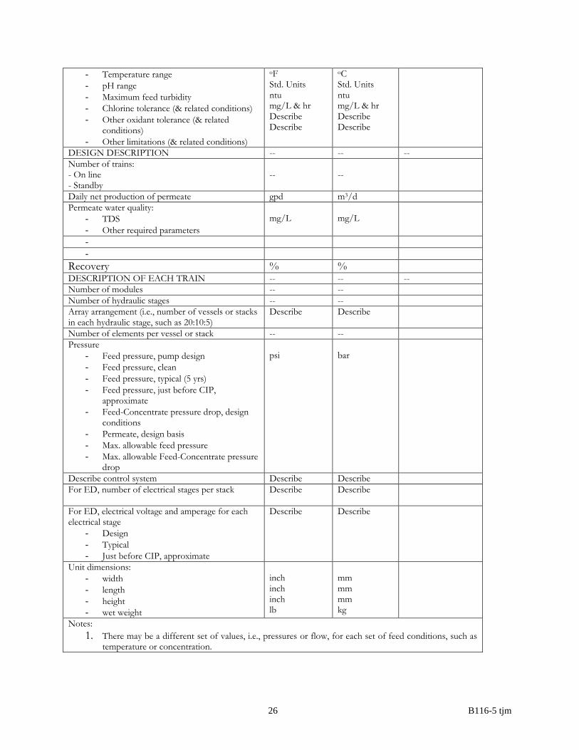
26 B116-5 tjm
- Temperature range
- pH range
- Maximum feed turbidity
- Chlorine tolerance (& related conditions)
- Other oxidant tolerance (& related conditions)
- Other limitations (& related conditions)
oF Std. Units ntu mg/L & hr Describe Describe
oC Std. Units ntu mg/L & hr Describe Describe
DESIGN DESCRIPTION -- -- --
Number of trains: - On line - Standby
--
--
Daily net production of permeate gpd m3/d
Permeate water quality:
- TDS
- Other required parameters
mg/L
mg/L
-
-
Recovery % % DESCRIPTION OF EACH TRAIN -- -- --
Number of modules -- --
Number of hydraulic stages -- --
Array arrangement (i.e., number of vessels or stacks in each hydraulic stage, such as 20:10:5)
Describe Describe
Number of elements per vessel or stack -- --
Pressure
- Feed pressure, pump design
- Feed pressure, clean
- Feed pressure, typical (5 yrs)
- Feed pressure, just before CIP, approximate
- Feed-Concentrate pressure drop, design conditions
- Permeate, design basis
- Max. allowable feed pressure
- Max. allowable Feed-Concentrate pressure drop
psi
bar
Describe control system Describe Describe
For ED, number of electrical stages per stack
Describe Describe
For ED, electrical voltage and amperage for each electrical stage
- Design
- Typical
- Just before CIP, approximate
Describe Describe
Unit dimensions:
- width
- length
- height
- wet weight
inch inch inch lb
mm mm mm kg
Notes:
1. There may be a different set of values, i.e., pressures or flow, for each set of feed conditions, such as temperature or concentration.