electrochemical energy engineering: a new...
TRANSCRIPT

CH05CH20-Yan ARI 20 May 2014 19:27
Electrochemical EnergyEngineering: A New Frontierof Chemical EngineeringInnovationShuang Gu, Bingjun Xu, and Yushan Yan
Department of Chemical and Biomolecular Engineering, University of Delaware, Newark,Delaware 19716; email: [email protected]
Annu. Rev. Chem. Biomol. Eng. 2014. 5:429–54
First published online as a Review in Advance onMarch 31, 2014
The Annual Review of Chemical and BiomolecularEngineering is online at chembioeng.annualreviews.org
This article’s doi:10.1146/annurev-chembioeng-060713-040114
Copyright c© 2014 by Annual Reviews.All rights reserved
Keywords
energy engineering, chemical engineering, electrochemical engineering,fuel cells, solar hydrogen generators, redox flow batteries
Abstract
One of the grand challenges facing humanity today is a safe, clean, and sus-tainable energy system where combustion no longer dominates. This reviewproposes that electrochemical energy conversion could set the foundationfor such an energy system. It further suggests that a simple switch from anacid to a base membrane coupled with innovative cell designs may lead to anew era of affordable electrochemical devices, including fuel cells, electrolyz-ers, solar hydrogen generators, and redox flow batteries, for which recentprogress is discussed using the authors’ work as examples. It also notes thatelectrochemical energy engineering will likely become a vibrant subdisci-pline of chemical engineering and a fertile ground for chemical engineeringinnovation. To realize this vision, it is necessary to incorporate fundamentalelectrochemistry and electrochemical engineering principles into the chem-ical engineering curriculum.
429
Ann
u. R
ev. C
hem
. Bio
mol
. Eng
. 201
4.5:
429-
454.
Dow
nloa
ded
from
ww
w.a
nnua
lrev
iew
s.or
g A
cces
s pr
ovid
ed b
y U
nive
rsity
of
Del
awar
e on
01/
27/1
8. F
or p
erso
nal u
se o
nly.

CH05CH20-Yan ARI 20 May 2014 19:27
FC: fuel cell
EL: electrolyzer
SH: solar hydrogengenerator
FB: flow battery
ELECTROCHEMICAL ENERGY ENGINEERING
Energy has been central to human civilization. The availability of affordable, abundant fossil energyhas been the primary driving force for much of the human progress made in the past 100+ years.With depleting fossil fuel reserves, increasing world population, growing expectations for highliving standards, and concerns over air quality and climate change, one of the grand challengesfacing humanity today is the development of an alternative energy system that is safe, clean, andsustainable, in which the combustion of fossil fuels no longer dominates.
Throughout human history, combustion has played a leading role in energy conversion. In acombustion process, reduction and oxidation (redox) reactions are coupled intimately, and elec-trons are transferred directly from the fuel to the oxidant to produce heat. Although this heat canbe used directly, it is more often converted to mechanical energy, most often via mechanical en-ergy to electricity, the most convenient form of energy. By contrast, in an electrochemical energyconversion process, the redox reactions are spatially separated by an electrolyte, allowing directextraction of electrons as electricity and leading to higher intrinsic energy conversion efficienciesand milder process conditions.
Electrochemical energy engineering can be considered a subdiscipline of chemical engineeringthat focuses on the design and operation of electrochemical energy devices and processes. Withtraining in chemistry, including electrochemistry, physics, mathematics, reaction engineering,transport, and thermodynamics, chemical engineers are best positioned to take the lead in elec-trochemical energy engineering. Electrochemical engineering with a broader scope that includeselectroplating, electrosynthesis, corrosion, and energy conversion has been a part of chemicalengineering programs for more than half a century. The research program established by CharlesW. Tobias in the 1950s at the University of California, Berkeley, and the Lawrence Berkeley Na-tional Laboratory pioneered the field of electrochemical engineering and trained generations ofelectrochemical engineers (1). A significant number of today’s leading electrochemical engineersin academia, industry, and national laboratories can trace their academic lineage to the Tobiasgroup. Another major contribution to the field of electrochemical engineering from the Berkeleygroup is John S. Newman’s textbook, Electrochemical Systems, which is a must-read for electro-chemical engineers. As society has refocused itself on developing a safe, clean, and sustainableenergy system, it has become clear that electrochemical energy devices will play a leading role,and as such, electrochemical energy engineering as a discipline is destined to grow and prosper inthe twenty-first century.
A NEW GENERATION OF AFFORDABLEELECTROCHEMICAL DEVICES
As a way to organize the research work carried out by the authors and others, an integrated electro-chemical energy system is envisioned consisting of the following electrochemical energy devices:fuel cells (FCs), electrolyzers (ELs), solar hydrogen generators (SHs), and redox flow batteries(FBs) (Figure 1). Fuel cells coupled with solar hydrogen generators and/or water electrolyzerscan provide clean power for mobile and stationary uses, whereas redox flow batteries are idealfor large-scale solar/wind electricity storage. With minor variations, all the aforementioned elec-trochemical devices share the same basic three-layer structure (electrode/membrane/electrode).Each electrode usually contains an appropriate catalyst to facilitate its designated redox reac-tion, and the electrode usually has a porous, thin-film structure that allows simultaneous electronconduction, ion conduction, and mass transport. One of the functions of the membrane is to
430 Gu · Xu · Yan
Ann
u. R
ev. C
hem
. Bio
mol
. Eng
. 201
4.5:
429-
454.
Dow
nloa
ded
from
ww
w.a
nnua
lrev
iew
s.or
g A
cces
s pr
ovid
ed b
y U
nive
rsity
of
Del
awar
e on
01/
27/1
8. F
or p
erso
nal u
se o
nly.

CH05CH20-Yan ARI 20 May 2014 19:27
SHSH
FBFB
FCFC
ELEL
Figure 1An integrated, safe, clean, and sustainable electrochemical energy system based on fuel cells (FCs), solarhydrogen generators (SHs), electrolyzers (ELs), and redox flow batteries (FBs). With minor variations, allthe aforementioned electrochemical devices share the same basic three-layer structure: electrode/membrane/electrode.
PEM: protonexchange membrane
HEM: hydroxideexchange membrane
selectively transport the common ion involved in the redox reactions between the electrodesto complete the electric circuit. The acid/base nature of the membrane fundamentally definesthe electrochemical reactions at the electrodes for fuel cells, solar hydrogen generators, andelectrolyzers.
This article is written as a perspective, rather than a comprehensive review, and as such itfocuses on using the authors’ recent work as examples to show that by switching from protonexchange membrane (PEM, an acid membrane) to hydroxide exchange membrane (HEM, a basemembrane), and by innovative designs of redox flow batteries, it is possible to eliminate the useof precious metals in fuel cells, solar hydrogen generators, and electrolyzers, which will lead to anew generation of affordable and commercially viable electrochemical systems.
www.annualreviews.org • Electrochemical Energy Engineering 431
Ann
u. R
ev. C
hem
. Bio
mol
. Eng
. 201
4.5:
429-
454.
Dow
nloa
ded
from
ww
w.a
nnua
lrev
iew
s.or
g A
cces
s pr
ovid
ed b
y U
nive
rsity
of
Del
awar
e on
01/
27/1
8. F
or p
erso
nal u
se o
nly.
CH05CH20-Yan ARI 20 May 2014 19:27
HYDROXIDE EXCHANGE MEMBRANE FUEL CELLS
Fuel Cells
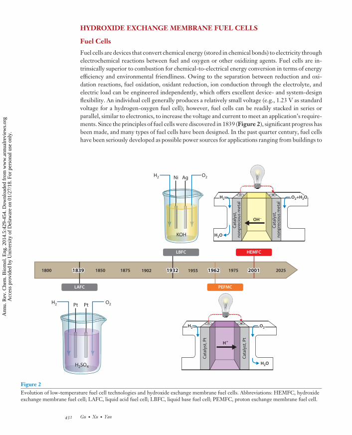
Fuel cells are devices that convert chemical energy (stored in chemical bonds) to electricity throughelectrochemical reactions between fuel and oxygen or other oxidizing agents. Fuel cells are in-trinsically superior to combustion for chemical-to-electrical energy conversion in terms of energyefficiency and environmental friendliness. Owing to the separation between reduction and oxi-dation reactions, fuel oxidation, oxidant reduction, ion conduction through the electrolyte, andelectric load can be engineered independently, which offers excellent device- and system-designflexibility. An individual cell generally produces a relatively small voltage (e.g., 1.23 V as standardvoltage for a hydrogen-oxygen fuel cell); however, fuel cells can be readily stacked in series orparallel, similar to electronics, to increase the voltage and current to meet an application’s require-ments. Since the principles of fuel cells were discovered in 1839 (Figure 2), significant progress hasbeen made, and many types of fuel cells have been designed. In the past quarter century, fuel cellshave been seriously developed as possible power sources for applications ranging from buildings to
H2 O2Ni Ag
KOH
H2 O2Pt Pt
H2SO4
+–H2H2
Cata
lyst
, no
npre
ciou
s m
etal
Cata
lyst
, no
npre
ciou
s m
etal
O2+H2OO2+H2O
H2OH2O
OH–
+––H2H2
Cata
lyst
, Pt
Cata
lyst
, Pt
O2O2
H+
H2O
LBFC
LAFC PEFMC
HEMFC
1800 185018391839 1902 19321932 1955 19621962 200120011875 1975 2025
Figure 2Evolution of low-temperature fuel cell technologies and hydroxide exchange membrane fuel cells. Abbreviations: HEMFC, hydroxideexchange membrane fuel cell; LAFC, liquid acid fuel cell; LBFC, liquid base fuel cell; PEMFC, proton exchange membrane fuel cell.
432 Gu · Xu · Yan
Ann
u. R
ev. C
hem
. Bio
mol
. Eng
. 201
4.5:
429-
454.
Dow
nloa
ded
from
ww
w.a
nnua
lrev
iew
s.or
g A
cces
s pr
ovid
ed b
y U
nive
rsity
of
Del
awar
e on
01/
27/1
8. F
or p
erso
nal u
se o
nly.

CH05CH20-Yan ARI 20 May 2014 19:27
LAFC: liquid acidfuel cell
HOR: hydrogenoxidation reaction
ORR: oxygenreduction reaction
SHE: standardhydrogen electrode
Load
Liquid acid
HOR
An
od
e
Ca
tho
de
H+ H+ + O2
H2
H2O
e–
Load
ORR
e–e–
Figure 3Working principle of liquid acid fuel cells. Abbreviations: HOR, hydrogen oxidation reaction; ORR, oxygenreduction reaction.
vehicles to portable electronics. In particular, hydrogen-fueled low-temperature (typically within0–100◦C) fuel cells are attractive, because hydrogen has high specific energy (34 kWh/kg, or 2.6times that of gasoline at 13 kWh/kg), and the use of hydrogen may be free of carbon footprints ifhydrogen is prepared from solar water splitting.
The nature of the electrolyte largely defines the materials selection for the other componentsand the operating conditions of a fuel cell; therefore, the electrolyte is usually used to categorizefuel cells. The evolution of low-temperature fuel cells has been very much driven by thedevelopment of the electrolytes (Figure 2). The principles of fuel cells were discovered in 1839using a liquid acid solution as an electrolyte. These cells are referred to here as liquid acid fuelcells (LAFCs). The basic structure of an LAFC includes a liquid acid electrolyte, an anode, acathode, and an external circuit (Figure 3). When hydrogen and oxygen are introduced andthe electric load is applied, hydrogen molecules are oxidized on the anode electrochemically,giving electrons to the anode and protons to the electrolyte. At the same time, oxygen moleculesare reduced on the cathode electrochemically, taking electrons from the cathode and protonsfrom the electrolyte and combining them to produce water. Driven by the electrical potentialdifference between the two electrodes, electrons move from anode to cathode as electric currentto do work through the external load. Driven by the concentration gradient established betweenthe two electrodes, protons diffuse from the anode to the cathode to complete the electric circuit.Combining the reactions at the anode and cathode, a fuel cell transforms energy from chemicalform to electrical form. Usually, electrocatalysts are used on both the anode and the cathode tofacilitate the electrode reactions: The hydrogen oxidation reaction (HOR) electrocatalyst is usedon the anode, and the oxygen reduction reaction (ORR) electrocatalyst is used on the cathode.The electrode reactions are as follows (based on pH = 0; SHE, standard hydrogen electrode):
Anode reaction (HOR) : 2H2 → 4H+ + 4e− E◦ = 0 V versus SHE
and
Cathode reaction (ORR) : O2 + 4H+ + 4e− → 2H2O E◦ = 1.23 V versus SHE.
www.annualreviews.org • Electrochemical Energy Engineering 433
Ann
u. R
ev. C
hem
. Bio
mol
. Eng
. 201
4.5:
429-
454.
Dow
nloa
ded
from
ww
w.a
nnua
lrev
iew
s.or
g A
cces
s pr
ovid
ed b
y U
nive
rsity
of
Del
awar
e on
01/
27/1
8. F
or p
erso
nal u
se o
nly.

CH05CH20-Yan ARI 20 May 2014 19:27
Load
PEM
HOR
An
od
e (
TP
B)
Ca
tho
de
(TP
B)
H+ H+ + O2
H2
H2O
e–
Load
ORR
e–e–
Figure 4Working principle of proton exchange membrane fuel cells. Abbreviations: HOR, hydrogen oxidationreaction; ORR, oxygen reduction reaction; PEM, proton exchange membrane; TPB, triple phase boundary.
PEMFC: protonexchange membranefuel cell
PEI: proton exchangeionomer
TPB: triple phaseboundary
However, the use of a liquid acid solution as the electrolyte poses many challenges to the devel-opment of LAFCs. Strong acids are usually used for LAFCs to lower ionic resistance, but theyare corrosive to most fuel cell materials (particularly metals, like electrocatalysts and containers),and their handling is also a safety concern. Besides, the liquid electrolytes tend to leak and makeLAFCs bulky, which limits the power density of LAFCs.
In 1950, solid polymer electrolytes, i.e., PEMs (based on a sulfonated polystyrene polymer),were invented (2). Compared with liquid acids, solid PEMs conduct protons similarly, but theyare much more convenient and safer to handle and use. PEMs are completely free of electrolyteleakage and are generally considered to be noncorrosive. PEMs were quickly adopted into fuel cells(i.e., PEM fuel cells, or PEMFCs), replacing the liquid acids in 1955 (Figure 2) (3). By switchingelectrolytes from liquid acids to solid polymers, PEMs offer great convenience for the use andengineering of PEMFCs. PEMFCs follow the same working principle as LAFCs (Figure 4), exceptfor two major differences: (a) The protons are conducted through polymer PEMs instead of liquidacids, and (b) the electrolyte/electrode interfaces are dominated by polymer PEM electrolytes, notliquid acids. The real breakthrough for PEMFCs came after DuPont invented Nafion R© PEM,based on a sulfonated, perfluorinated polymer, in 1962. Nafion polymer not only can be used as anexcellent PEM but also can serve as a highly dispersed proton exchange ionomer (PEI) necessaryto create an efficient triple phase boundary (TPB) in electrodes (4). TPB is the only place in theelectrode where redox reactions occur because it allows a catalyst such as platinum (Pt) to havesimultaneous access to the electron-conducting channel, proton-conducting channel, and fuel oroxidant channel. The dual function of the Nafion polymer, as well as its outstanding chemical,thermal, and mechanical stability, has enabled PEMFCs to have exceptionally high specific power(above 1 kW/kg) and good device durability (thousands of hours) (5). The success of PEMFCshas stimulated the research and commercialization interests in fuel cells in the past half century.
PEMs provide a proton-mediated environment for electrode reactions that intrinsically re-quires precious metals (typically Pt) as electrocatalysts for high-performance PEMFCs. The designand development of stable and active nonprecious metal–based electrocatalysts are very challenging
434 Gu · Xu · Yan
Ann
u. R
ev. C
hem
. Bio
mol
. Eng
. 201
4.5:
429-
454.
Dow
nloa
ded
from
ww
w.a
nnua
lrev
iew
s.or
g A
cces
s pr
ovid
ed b
y U
nive
rsity
of
Del
awar
e on
01/
27/1
8. F
or p
erso
nal u
se o
nly.
CH05CH20-Yan ARI 20 May 2014 19:27
Load
HEM
HOR
An
od
e (
TP
B)
Ca
tho
de
(TP
B)
H2O + O2
H2 + OH– OH–
H2O
e–
Load
ORR
e–e–
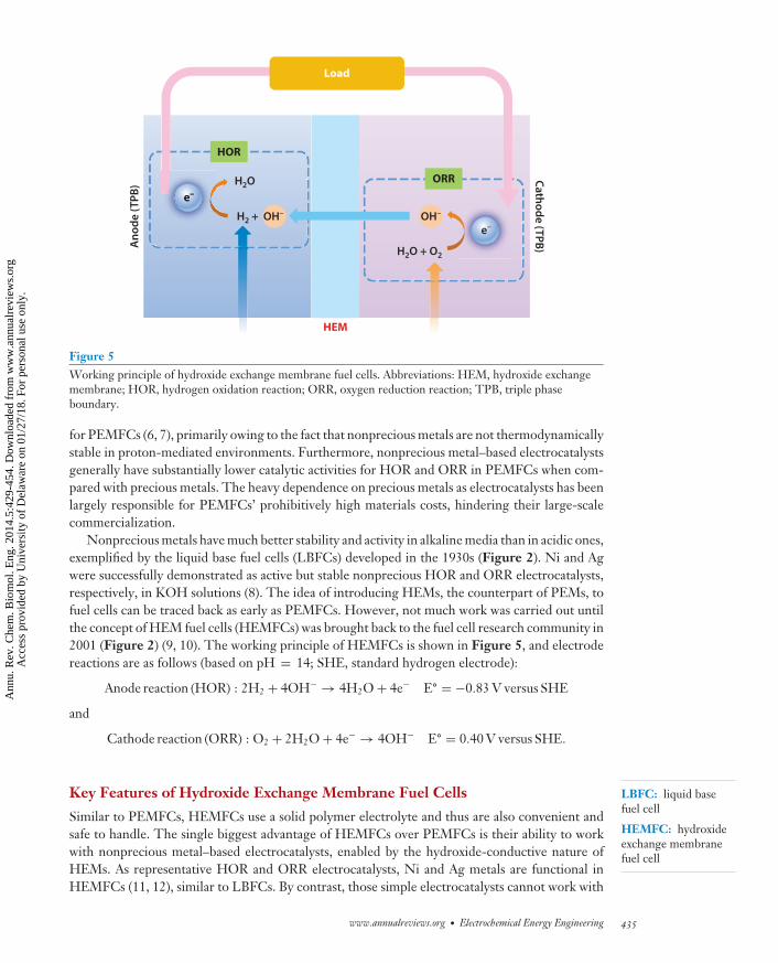
Figure 5Working principle of hydroxide exchange membrane fuel cells. Abbreviations: HEM, hydroxide exchangemembrane; HOR, hydrogen oxidation reaction; ORR, oxygen reduction reaction; TPB, triple phaseboundary.
LBFC: liquid basefuel cell
HEMFC: hydroxideexchange membranefuel cell
for PEMFCs (6, 7), primarily owing to the fact that nonprecious metals are not thermodynamicallystable in proton-mediated environments. Furthermore, nonprecious metal–based electrocatalystsgenerally have substantially lower catalytic activities for HOR and ORR in PEMFCs when com-pared with precious metals. The heavy dependence on precious metals as electrocatalysts has beenlargely responsible for PEMFCs’ prohibitively high materials costs, hindering their large-scalecommercialization.
Nonprecious metals have much better stability and activity in alkaline media than in acidic ones,exemplified by the liquid base fuel cells (LBFCs) developed in the 1930s (Figure 2). Ni and Agwere successfully demonstrated as active but stable nonprecious HOR and ORR electrocatalysts,respectively, in KOH solutions (8). The idea of introducing HEMs, the counterpart of PEMs, tofuel cells can be traced back as early as PEMFCs. However, not much work was carried out untilthe concept of HEM fuel cells (HEMFCs) was brought back to the fuel cell research community in2001 (Figure 2) (9, 10). The working principle of HEMFCs is shown in Figure 5, and electrodereactions are as follows (based on pH = 14; SHE, standard hydrogen electrode):
Anode reaction (HOR) : 2H2 + 4OH− → 4H2O + 4e− E◦ = −0.83 V versus SHE
and
Cathode reaction (ORR) : O2 + 2H2O + 4e− → 4OH− E◦ = 0.40 V versus SHE.
Key Features of Hydroxide Exchange Membrane Fuel Cells
Similar to PEMFCs, HEMFCs use a solid polymer electrolyte and thus are also convenient andsafe to handle. The single biggest advantage of HEMFCs over PEMFCs is their ability to workwith nonprecious metal–based electrocatalysts, enabled by the hydroxide-conductive nature ofHEMs. As representative HOR and ORR electrocatalysts, Ni and Ag metals are functional inHEMFCs (11, 12), similar to LBFCs. By contrast, those simple electrocatalysts cannot work with
www.annualreviews.org • Electrochemical Energy Engineering 435
Ann
u. R
ev. C
hem
. Bio
mol
. Eng
. 201
4.5:
429-
454.
Dow
nloa
ded
from
ww
w.a
nnua
lrev
iew
s.or
g A
cces
s pr
ovid
ed b
y U
nive
rsity
of
Del
awar
e on
01/
27/1
8. F
or p
erso
nal u
se o
nly.

CH05CH20-Yan ARI 20 May 2014 19:27
HEI: hydroxideexchange ionomer
PEMFCs to generate a meaningful current (13). In principle, other nonprecious metal–basedelectrocatalysts with similar or even lower materials costs are potentially feasible for HEMFCs.In addition to higher activities, nonprecious metal–based electrocatalysts are also more durable inHEMFCs than in PEMFCs.
Fuel crossover, the unwanted transport of fuel through polymer electrolytes from anode tocathode, leads to lower fuel cell efficiency owing to poor fuel use and, more significantly, unde-sirable mixed electrical potential on the cathode. In PEMFCs, the fuel crossover is aggravatedbecause the protons move in the same direction as the fuel crossover. This makes it difficultfor PEMFCs to use the thinner membranes desired for reducing PEM’s ionic resistance. Thecrossover is particularly significant for hydrogen because it has the smallest molecule size. Bycontrast, in HEMFCs, hydroxides move from cathode to anode, opposite to the fuel-crossoverdirection. The low fuel crossover allows for ultrathin HEMs (as thin as 10 μm, A901 commer-cial HEM from Tokuyama Co.) to be used without compromising the cathode potential. Theultralow thickness also helps overcome the intrinsically lower conductivity of hydroxides whencompared with protons. Hydroxides have approximately half the ion mobility of protons [20.50versus 36.25 × 10⁻⁴ cm2 V−1 s−1 in water at 25◦C (14)]. For example, with one-third to one-halfof the ion conductivity of PEMs, HEMs with one-half to one-fifth of the membrane thicknesswill have a membrane resistance comparable to that of PEMs. Low HEM membrane resistance(as low as 25 m�cm2) makes high-performance HEMFCs possible, and power density as highas 730 mW/cm2 was reported in an H2/O2 HEMFC at 80◦C (15), close to the state-of-the-artperformances of PEMFCs. The hydroxide environment of HEMFCs also favors the oxidationof more complex molecules, broadening fuels choices (16) to alcohols [e.g., methanol, ethyleneglycol (17), ethanol (18), and glycerol (19)], hydrazine (20), ammonia (21), and even glucose (22).
CO2 contamination has been a critical hurdle for LBFCs, especially for terrestrial applica-tions (LBFCs have been successfully used for the NASA space program). CO2 from ambientair or hydrocarbon complete oxidation can irreversibly react with the liquid bases, which lowersthe electrolyte conductivity. More importantly, the CO2 contamination brings a fatal threat toLBFCs’ porous electrodes via the formation of metal carbonate/bicarbonate crystals (23). Similarto LBFCs, CO2 is also able to contaminate the HEM electrolytes and convert hydroxides to car-bonates/bicarbonates, lowering the HEMs’ conductivity. However, unlike liquid base electrolytes,HEMs do not possess any freely mobile metal cations, eliminating the possibility of the formationof carbonate/bicarbonate crystals. Unlike that of LBFCs, CO2 contamination has been confirmedto be reversible in HEMFCs: Bicarbonate/carbonate can be displaced from HEMs by HEMFCoperations, replenishing hydroxides in the HEMs (24, 25). Owing to the outstanding advantagesmentioned above, HEMFCs have been drawing increasing attention from academia, industry, andgovernments globally (10, 11, 26–33).
Key Components of HEMFCs
HEMs and HEIs. HEM is used between the electrodes, and its central function is to provide themedium for hydroxide transport between the electrodes to complete the cell’s electrical circuit.It also serves as an insulator to prevent electron conduction between two electrodes to avoidshort circuit and as a separator between the fuel and the oxidant to avoid mixing. Hydroxideexchange ionomers (HEIs) are dispersed among the catalyst particles within the catalyst layer of theelectrodes. They provide the hydroxide environment for the catalysts to mediate electrochemicalreactions as well as the ion-conducting channels from the catalytic sites to the HEM.
HEMs are made by cation-functionalized polymers consisting of two main structural com-ponents: cationic functional groups that provide hydroxide conductivity and nonionic polymer
436 Gu · Xu · Yan
Ann
u. R
ev. C
hem
. Bio
mol
. Eng
. 201
4.5:
429-
454.
Dow
nloa
ded
from
ww
w.a
nnua
lrev
iew
s.or
g A
cces
s pr
ovid
ed b
y U
nive
rsity
of
Del
awar
e on
01/
27/1
8. F
or p
erso
nal u
se o
nly.

CH05CH20-Yan ARI 20 May 2014 19:27
chains (main chains and/or side chains) that afford membrane robustness. The most commonHEM cations are quaternary ammoniums, in which the nitrogen atoms bear one unit of positivecharge and serve as the hydroxide-conducting centers. There are many polymers to choose fromfor the polymer main chains (27, 31, 34).
Anchoring cationic functional groups to polymer matrices is the main subject of HEM poly-mer synthesis. Typical synthetic recipes include direct polymerization of functional monomers,chemical functionalization of polymers, and radiation-grafting functionalization of membranes.Chemical crosslinking, physical crosslinking, and membrane reinforcement are often adopted totune solvent resistance, dimensional stability, membrane hydration, and mechanical properties forHEMs.
The cationic functional groups are of particular importance and have profound impacts onproperties of HEMs. Solubility; chemical, thermal, and mechanical stability; and the intrinsicefficiency of hydroxide conduction are all greatly controlled by HEM cations (35–37). Therefore,the design, synthesis, and characterization of cations have been some of the most importantresearch focuses in the HEM research community. In addition to ammoniums, many new cations,such as phosphonium (35), sulfonium (38), guanidinium (39), imidazolium (40), and ruthenium(41), have been introduced and explored, bringing new features and great possibilities of designingversatile HEMs for various HEMFC applications.
HEIs are also an important component of HEMFCs. Similar to PEIs for PEMFCs, HEIs func-tion to create efficient TPBs in electrodes necessary for high-performance HEMFC operations(35). The creation of a TPB depends on good dispersion and high hydroxide conductivity in thecatalyst layer. Good solubility in low-boiling-point, water-miscible solvents is generally neededfor HEI polymers to achieve excellent dispersion. High conductivity will allow for fast hydroxidetransport, facilitating electrode reactions. For example, phosphonium cation-based HEI polymers(35, 42) have both desired selective solubility (in alcohols) and high hydroxide conductivity [up to55 mS/cm at 20◦C (42)], which makes them promising high-performance HEIs.
Nonprecious metal ORR and HOR electrocatalysts. ORR and HOR electrocatalysts arerequired to facilitate the two electrode reactions. Generally, the ORR kinetics is considered tobe more facile in bases than in acids. The reason usually can be rationalized by less absorptionof spectator ions (balancing anions of acids and balancing cations of bases) that physically blockcatalyst active sites, and/or more absorption of hydroxide that may thermodynamically favor theinitiation of electron depletion from oxygen molecules (43, 44). This is particularly true for non-Ptmetals. For example, Ag was shown to have 450 mV more positive ORR half-wave-potential in 0.1M KOH than in 0.1 M HClO4 by the rotating disk method (45), which implies approximately sixorders of magnitude–higher ORR exchange current density when based on 70 mV/dec of Tafelslope. Higher exchange current density means higher intrinsic catalytic activity, whereas lowerTafel slope indicates that larger activity increases with overpotential.
The complete reduction of one oxygen molecule involves the transfer of four electrons, leadingto complex electrocatalytic reactions. A four-electron reaction pathway is much more preferred forORR electrocatalysts than a two-electron reaction pathway, which produces hydrogen peroxideanions (HO2
−) in alkaline media.Owing to the inherently enhanced kinetics and improved stability, a wide range of ORR electro-
catalysts have been studied for alkaline systems, among which nonprecious metal electrocatalystsare of particular interest. Typical nonprecious metal ORR electrocatalysts are based on materi-als including silver metal/alloys, manganese oxides, perovskite-/spinel-type transition metal ox-ides, and macrocycle transition metal complexes (46–49). With relatively low cost and reasonablyhigh activity, Ag has been considered an efficient ORR electrocatalyst for HEMFCs. Ag has
www.annualreviews.org • Electrochemical Energy Engineering 437
Ann
u. R
ev. C
hem
. Bio
mol
. Eng
. 201
4.5:
429-
454.
Dow
nloa
ded
from
ww
w.a
nnua
lrev
iew
s.or
g A
cces
s pr
ovid
ed b
y U
nive
rsity
of
Del
awar
e on
01/
27/1
8. F
or p
erso
nal u
se o
nly.

CH05CH20-Yan ARI 20 May 2014 19:27
MEA: membraneelectrode assembly
approximately 10% of the ORR-specific activity of Pt in alkaline solutions (12), but Ag has 100times the elemental abundance of Pt in the earth’s crust (and roughly 1% of the cost of Pt). Nano-structure has a great impact on Ag’s ORR performance; for example, Ag nanowires with a certain di-ameter have been demonstrated to achieve higher ORR activity than simple Ag nanoparticles (50).Also, Ag was shown to be more stable than Pt during long-term operation in LBFCs (51). Othernonprecious metal–based electrocatalysts (52–55) also hold promise for HEMFC applications.
HOR electrocatalysts are also required to facilitate hydrogen oxidation. In general, HORkinetics is widely considered much more facile than ORR kinetics in both acid and base. Ni-basednanoparticles have been introduced as nonprecious HOR electrocatalysts for HEMFCs (11, 12).Although a precious metal, Pd can be considered owing to its high HOR activity (compared withNi) and moderate cost (compared with Pt). Together with controlled metal loadings, Pd is apotentially viable material for HOR electrocatalysts for HEMFC applications.
Key Challenges of HEMFCs
Development of highly durable HEMs/HEIs. Sufficient durability is required for HEMFCs forcommercial applications. For example, a few thousand hours (5,000 h preferred) of durability aregenerally needed for transportation applications. However, there is a significant gap between thedemonstrated and the required HEMFC durability: The state-of-the-art HEMFCs were shownto afford less than 500 h of durability with more than 1,000 μV/h of cell voltage degradationrate at 50◦C cell temperature (56). Such a degradation rate of HEMFCs is at least one order ofmagnitude higher than that of PEMFCs. To deliver high cell performances and to reduce CO2
impact, cell temperatures higher than 50◦C (e.g., 80◦C) are necessary. Higher cell temperaturewill accelerate the degradation of HEMs and exacerbate the durability problem.
The state-of-the-art HEMs have durability in ex situ tests in pure water, for example, 2,000 hat 80◦C (57) or 500 h at 90◦C (58), suggesting a good potential to meet the durability target.The poor HEMFC durability observed may have been caused primarily by HEI degradation inelectrodes, because HEIs work at the TPB, where they are much more stressed than the HEMs.However, the degradation mechanisms of HEIs in membrane electrode assemblies (MEAs) havenot been revealed in situ yet. New in situ sensor/diagnostic techniques for MEA degradationmay help uncover the HEI degradation mechanisms. Such understanding would be crucial to thedesign of next-generation HEIs with much higher stability. Both cationic functional groups andpolymer chain structures are considered responsible for HEI degradations in MEAs; thus, bothof them must be improved against both (HO2
−) oxidative attacks and (OH−) nucleophilic attacksin electrodes. The authors consider this one of the most important research topics in developinghigh-performance HEM/HEI polymer electrolytes.
Development of highly active nonprecious metal HOR electrocatalysts. The HOR ex-change current densities on many metal surfaces in base solutions are comparable to those in acidsolutions (generally within one order of magnitude) (59, 60), but the HOR Tafel slopes appearmuch larger in base than in acid [e.g., four times on Pt polycrystalline surface: 120 mV/dec in0.1 M KOH (61) versus ∼30 mV/dec in 0.5 M H2SO4 (62, 63)]. The difference between acids andbases for HOR activity is likely to be related to hydrogen binding energy and hydroxide adsorption(60, 64, 65); however, the detailed mechanisms are still elusive.
Large Tafel slopes will inevitably require large overpotential for fuel cell operations, especiallyat high current densities. It is even more challenging to use nonprecious metal HOR electrocat-alysts because they have much lower exchange current densities [e.g., two orders of magnitudesmaller on Ni than on Pt: 10−5.5 (66) versus 10−3.5 A/cm2 (63) for Ni versus Pt in 0.5 M NaOH].
438 Gu · Xu · Yan
Ann
u. R
ev. C
hem
. Bio
mol
. Eng
. 201
4.5:
429-
454.
Dow
nloa
ded
from
ww
w.a
nnua
lrev
iew
s.or
g A
cces
s pr
ovid
ed b
y U
nive
rsity
of
Del
awar
e on
01/
27/1
8. F
or p
erso
nal u
se o
nly.

CH05CH20-Yan ARI 20 May 2014 19:27
One strategy to increase the HOR activity is to increase the exchange current density by tuningthe metal–hydrogen binding energy, because the exchange current density on metal surfaces canbe well correlated with their metal-hydrogen-binding energies (59, 67). Another possibility is todirectly reduce the Tafel slope by tuning the hydroxide adsorption or completely changing theelectrode reaction mechanisms. Development of nonprecious metal electrocatalysts has becomeanother important research need for commercialization of HEMFCs.
The electrolyte/electrode interface of HEMFCs can behave very differently from LBFCs (12,68). The characterization of interfacial structure and understanding of fundamental characteristicsof the HEMFC electrode/electrolyte interface may help shed light on designing and developinghighly active nonprecious metal HOR electrocatalysts.
Fabrication of high-performance electrodes and MEAs. Although HEMFCs share basicMEA structures with PEMFCs, there are clear differences between the two types of fuel cells.In particular, the roles of water and subsequently water management are fundamentally different.In PEMFCs, water is a simple product generated in cathodes. In HEMFCs, water serves as areactant participating in the ORR in cathode and regenerated in the HOR in anode. The watermanagement is considered much more complex for HEMFCs than for PEMFCs. Traditionalhighly hydrophobic electrode structures of PEMFCs may not be suitable for HEMFCs, as theycannot provide efficient water transport needed for HEMFC cathodes. For example, a currentdensity as low as 50 mA/cm2 was found to show apparent water transport impact on HEMFC cellvoltage when traditional carbon papers designed for PEMFCs were used as electrode substratesfor HEMFCs (69). There is a hurdle for HEMFC electrode design for efficient water transportfor HEMFCs to compete with the state-of-the-art PEMFCs that have no appreciable water trans-port impact below the current density of 500 mA/cm2. The hydrophobicity of the carbon backingpapers must be carefully engineered and balanced for electrodes for HEMFCs to deliver high cellperformances.
The fabrication method of high-performance MEAs is another challenge for HEMFCs. Thetraditional MEA fabrication method of PEMFCs is based on the hot-press method, because NafionPEI polymer softens at approximately 135◦C without losing its chemical integrity. The hot-press fabrication method helps to seamlessly glue the membrane and the two electrodes together,reducing overall MEA resistance and leading to very high MEA performance. Being soluble insome low-boiling-point and water-miscible solvents, many HEI polymers can easily create efficientelectrodes, but none of the HEI polymers available today are suitable to a Nafion-like hot-pressprocess. Therefore, great concerns exist for an efficient interface between the membrane and thetwo electrodes. Catalyst-coated-membrane technique may be helpful to improve the connectionbetween membrane and electrodes, alleviating the need for a hot-press process. MEA engineeringis urgently needed to solve these technological challenges for HEMFCs.
SOLAR HYDROGEN GENERATORS
Photoelectrochemical Cells for Solar Hydrogen Production via Water Splitting
The efficient conversion of photons in sunlight to energy stored in chemical bonds (e.g., theH-H bond in hydrogen) via photoelectrochemical water splitting is one of the most sought-after goals, owing to the clean and inexhaustible nature of solar energy. A tremendous amountof progress has been made in the field of solar-to-electricity conversion (i.e., photovoltaics) inthe past quarter century (70–73). However, the intrinsic intermittency of solar energy on a dailycycle poses a serious challenge to the electric grid as the portion of electricity produced from
www.annualreviews.org • Electrochemical Energy Engineering 439
Ann
u. R
ev. C
hem
. Bio
mol
. Eng
. 201
4.5:
429-
454.
Dow
nloa
ded
from
ww
w.a
nnua
lrev
iew
s.or
g A
cces
s pr
ovid
ed b
y U
nive
rsity
of
Del
awar
e on
01/
27/1
8. F
or p
erso
nal u
se o
nly.
CH05CH20-Yan ARI 20 May 2014 19:27
Conduction band
Valence band
Photocatalyst
E/Vversus SHE
CBM
VBM
e–
h+
SemiconductorLight harvesting
ElectrocatalystsWater splitting
O2 + H+
H2O
Photon
Protonconduction
ElectrolyteMass transport
H+/H2, 0 V
O2/H2O, 1.23 V
Band gap
H+
H2
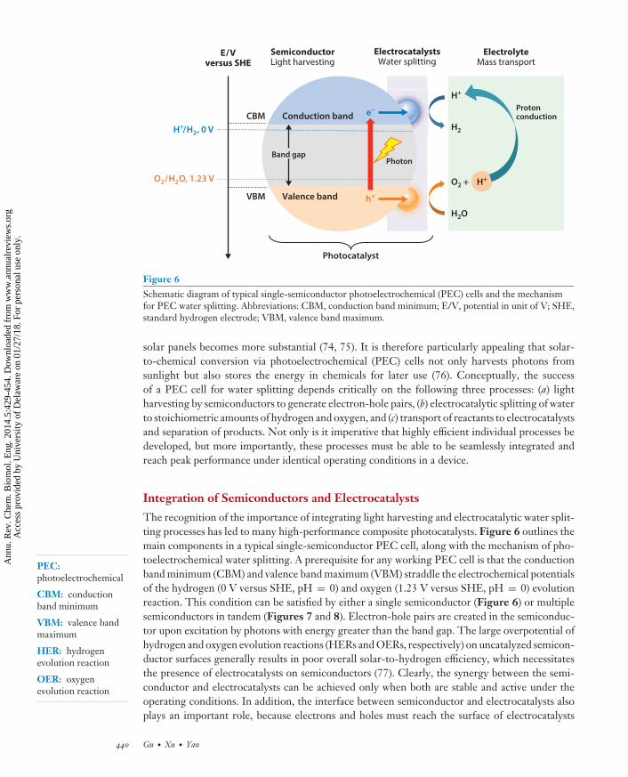
Figure 6Schematic diagram of typical single-semiconductor photoelectrochemical (PEC) cells and the mechanismfor PEC water splitting. Abbreviations: CBM, conduction band minimum; E/V, potential in unit of V; SHE,standard hydrogen electrode; VBM, valence band maximum.
PEC:photoelectrochemical
CBM: conductionband minimum
VBM: valence bandmaximum
HER: hydrogenevolution reaction
OER: oxygenevolution reaction
solar panels becomes more substantial (74, 75). It is therefore particularly appealing that solar-to-chemical conversion via photoelectrochemical (PEC) cells not only harvests photons fromsunlight but also stores the energy in chemicals for later use (76). Conceptually, the successof a PEC cell for water splitting depends critically on the following three processes: (a) lightharvesting by semiconductors to generate electron-hole pairs, (b) electrocatalytic splitting of waterto stoichiometric amounts of hydrogen and oxygen, and (c) transport of reactants to electrocatalystsand separation of products. Not only is it imperative that highly efficient individual processes bedeveloped, but more importantly, these processes must be able to be seamlessly integrated andreach peak performance under identical operating conditions in a device.
Integration of Semiconductors and Electrocatalysts
The recognition of the importance of integrating light harvesting and electrocatalytic water split-ting processes has led to many high-performance composite photocatalysts. Figure 6 outlines themain components in a typical single-semiconductor PEC cell, along with the mechanism of pho-toelectrochemical water splitting. A prerequisite for any working PEC cell is that the conductionband minimum (CBM) and valence band maximum (VBM) straddle the electrochemical potentialsof the hydrogen (0 V versus SHE, pH = 0) and oxygen (1.23 V versus SHE, pH = 0) evolutionreaction. This condition can be satisfied by either a single semiconductor (Figure 6) or multiplesemiconductors in tandem (Figures 7 and 8). Electron-hole pairs are created in the semiconduc-tor upon excitation by photons with energy greater than the band gap. The large overpotential ofhydrogen and oxygen evolution reactions (HERs and OERs, respectively) on uncatalyzed semicon-ductor surfaces generally results in poor overall solar-to-hydrogen efficiency, which necessitatesthe presence of electrocatalysts on semiconductors (77). Clearly, the synergy between the semi-conductor and electrocatalysts can be achieved only when both are stable and active under theoperating conditions. In addition, the interface between semiconductor and electrocatalysts alsoplays an important role, because electrons and holes must reach the surface of electrocatalysts
440 Gu · Xu · Yan
Ann
u. R
ev. C
hem
. Bio
mol
. Eng
. 201
4.5:
429-
454.
Dow
nloa
ded
from
ww
w.a
nnua
lrev
iew
s.or
g A
cces
s pr
ovid
ed b
y U
nive
rsity
of
Del
awar
e on
01/
27/1
8. F
or p
erso
nal u
se o
nly.

CH05CH20-Yan ARI 20 May 2014 19:27
Photon
Photon
Ohmic contact
n-SC
p-SC
E/Vversus SHE
Anode Cathode
H+/H2, 0 V
O2/H2O, 1.23 V
E/Vversus SHE
e–
h+
e–
h+
PEM
H2O
H+ + O2
H+
H2
Figure 7Schematic diagram of photoelectrochemical cells with a proton exchange membrane (PEM) separating theanode and cathode. Abbreviations: E/V, potential in unit of V; SHE, standard hydrogen electrode.
before they can participate in the water splitting reactions. Domen and others (78–83) have madesignificant progress in developing semiconductors with precise control of the width of the bandgap and positions of the band edges and cocatalysts for photoelectrochemical water splitting (e.g.,metal nitrides and oxynitrides). Although the electrocatalysts for HERs and OERs are depicted asseparate particles, in reality, they can be the same type of material, as in the case of one-step watersplitting cells (Figure 6), or two different materials, as in two-step water splitting cells (Figures 7and 8). One important limitation of the type of PEC cells shown in Figure 6 is that hydrogen andoxygen productions are not spatially separated, which clearly poses a safety challenge. Further-more, the separation of hydrogen from the hydrogen/oxygen mixture is also an energetically costlyprocess, which would lower the overall efficiency of the solar-to-chemical conversion. In this case,the transport of reactants (i.e., water and proton) is typically accomplished via liquid electrolyte.
PEC Cells with Built-In Product Separation
An improved PEC cell design has HERs and OERs occurring on the surfaces of a spatially separatedcathode and anode (Figure 7). A PEM is employed to physically separate the anode and cathodeand thus prevent the mixing of hydrogen and oxygen upon formation. Because water is present onboth electrodes (PEMs must be moisturized at all times to operate), it is advantageous to engineerthe CBM of the semiconductor (typically p-type) of the cathode side to be lower in electrochemicalpotential than that of HERs, while keeping the VBM lower than the electrochemical potentialof OERs. The converse is true on the anode side. Upon illumination, electron-hole pairs areformed in semiconductors on both sides. The excited electrons in the conduction band of then-type semiconductor on the anode move toward the ohmic contact to neutralize the holes ofthe p-type semiconductor of the cathode. The excited holes on the anode and electrons on thecathode are responsible for OER and HER, respectively. Therefore, hydrogen and oxygen areseparated from the moment of formation in this cell configuration. An added benefit of the PEM
www.annualreviews.org • Electrochemical Energy Engineering 441
Ann
u. R
ev. C
hem
. Bio
mol
. Eng
. 201
4.5:
429-
454.
Dow
nloa
ded
from
ww
w.a
nnua
lrev
iew
s.or
g A
cces
s pr
ovid
ed b
y U
nive
rsity
of
Del
awar
e on
01/
27/1
8. F
or p
erso
nal u
se o
nly.

CH05CH20-Yan ARI 20 May 2014 19:27
(∼50 μm in thickness) is the reduced volume needed for proton conduction as compared witha liquid electrolyte. Lewis et al. (84, 85) pioneered PEM-based PEC cells for solar hydrogen. Avast amount of literature has been dedicated to the engineering of the position and width of bandgap of both photoanodes and photocathodes (77). Moreover, the design and structure-reactivityrelation of electrocatalysts to facilitate the HER and OER have also been areas of intense research.
The type of solid electrolyte employed in a PEC cell largely determines its operating envi-ronment (e.g., PEM for acidic and HEM for alkaline conditions, respectively). The stability andperformance of photocatalysts depend sensitively on the pH of the operating environment (86).For example, most nonprecious metal electrocatalysts (e.g., Ni, Co, Ag) are not stable in stronglyacidic media, which makes noble metals (e.g., Pt, Ru, Ir, Re) irreplaceable components of the elec-trocatalysts in PEM-based PEC cells. For solar hydrogen to make up a meaningful portion in theoverall world energy mix, the cost of hydrogen produced via PEC cells must be competitive withhydrogen from other sources (e.g., steam cracking of hydrocarbons from fossil fuels). Therefore,precious metals in the PEC cells must be replaced by more affordable materials. Two approacheshave been explored to reach this goal: (a) development of nonprecious metal electrocatalysts thatare stable and active under acidic conditions and (b) switching to an HEM-based PEC cell design,because many existing nonprecious metal electrocatalysts (e.g., Ag, Ni) are stable and active underalkaline conditions (Y. Yan, lecture notes for ChE155, Caltech, 2010). We focus our discussionon the second approach in the rest of this section.
HEM-Based PEC Cells and Perspective
The general configuration of HEM-based PEC cells is similar to that of PEM-based cells(Figure 8), albeit with several key differences: (a) The operating environment of the HEM-basedPEC cells is alkaline, and the ion that completes the electrical circuit is OH−, in contrast to
Ohmic contact
n-SC
p-SC
H+/H2, –0.83 V
O2/OH–, 0.40 V
E/Vversus SHE
Anode Cathode E/Vversus SHE
Photon
HEM
e–
h+
Photon
e–
h+
H2O + O2
OH–
H2O
H2 + OH–
Figure 8Schematic diagram of a photoelectrochemical cell with a hydroxide exchange membrane (HEM) separatingoxygen and hydrogen produced at anode and cathode, respectively. Abbreviations: E/V, potential in unit ofV; SHE, standard hydrogen electrode.
442 Gu · Xu · Yan
Ann
u. R
ev. C
hem
. Bio
mol
. Eng
. 201
4.5:
429-
454.
Dow
nloa
ded
from
ww
w.a
nnua
lrev
iew
s.or
g A
cces
s pr
ovid
ed b
y U
nive
rsity
of
Del
awar
e on
01/
27/1
8. F
or p
erso
nal u
se o
nly.

CH05CH20-Yan ARI 20 May 2014 19:27
IEM: ion-exchangemembrane
the acidic environment of PEM-based PEC cells with a proton as the charge-carrying ion, and(b) under alkaline conditions, the photoanode and photocathode reactions are as follows.
Photoanode reaction : 4OH− → 2H2O + O2 + 4e− E◦ = 0.40 V versus SHE
and
Photocathode reaction : 4H2O + 4e− → 2H2 + 4OH− E◦ = −0.83 V versus SHE.
Therefore, the positions of the VBM and CBM of the semiconductors in the photoanode andphotocathode of HEM-based cells must be engineered to different electrochemical potentialsthan those in PEM-based cells, to ensure hydrogen and oxygen are formed only on the cathodeand anode, respectively. The main advantage of the HEM-based architecture is that it affords thepossibility of the exclusive use of nonprecious metal electrocatalysts to achieve similar or evenhigher efficiency of the HER and OER, as compared with the performance of PEM-based PECcells loaded with precious metal electrocatalysts. Our recent work has demonstrated that the com-bination of Ag electrocatalyst and phosphonium-based HEM shows slightly higher activity than aPt-based catalyst under identical conditions for ORR (12), which is the reverse reaction for the an-ode reaction in the PEC cells. According to the principle of microscopic reversibility, Ag is likely tobe an active catalyst for OER on the anode of PEC cells. Preliminary experiments have also shownseveral nonprecious metals that are stable and active for HER and OER under alkaline conditions.
We believe the time for developing HEM-based PEC cells has matured on both societal andtechnological fronts. Increasing public awareness about the undesirable impacts of our heavy re-liance on fossil fuels on the environment and climatic patterns drives the search for clean andsustainable sources of energy. Furthermore, recent technological advancements have put the de-velopment of most of the key components for HEM-based PEC cells in the foreseeable futurewithin reach, for example, the enhanced ion conductivity and stability of HEM and the active,stable, and affordable electrocatalysts for HOR and ORR under alkaline conditions (Figure 9).The authors believe breakthroughs in the following three areas are necessary for the success ofHEM-based PEC cells: (a) development of semiconductors stable under alkaline conditions, withband gaps precisely engineered for HER and OER under alkaline conditions; (b) development ofHEMs with long-term stability under visible and UV irradiation; and (c) development of active,stable, and nonprecious metal–based electrocatalysts for HER and OER under alkaline conditions.Further, on the cell-design level, the three key components (i.e., semiconductor, electrocatalyst,and HEM) must be able to operate, if not to reach peak performance, under identical environments(e.g., pH, temperature, and pressure). Finally, the efficient transport of chemicals, electrons, andions to and across the interfaces among these components is another indispensable attribute forHEM-based PEC cells.
FLOW BATTERIES
Flow batteries are rechargeable batteries that can reversibly convert electrical energy to chemicalenergy. The key difference between a flow battery and the traditional rechargeable battery isthat the traditional rechargeable batteries store electricity internally in their redox pairs (negativeand positive redox pairs) fixed on the two electrodes (negative and positive electrodes), whereasflow batteries store their energy externally in two flowing electrolytes (negative and positiveelectrolytes) enabled by a selective ion-exchange membrane (IEM) that on one hand isolates theelectroactive redox ions and on the other conducts the balancing ions between two electrolytes.The energy storage and power delivery functions are fundamentally decoupled in flow batteries,leading to great design flexibility and system scalability. The transfer of the energy storage function
www.annualreviews.org • Electrochemical Energy Engineering 443
Ann
u. R
ev. C
hem
. Bio
mol
. Eng
. 201
4.5:
429-
454.
Dow
nloa
ded
from
ww
w.a
nnua
lrev
iew
s.or
g A
cces
s pr
ovid
ed b
y U
nive
rsity
of
Del
awar
e on
01/
27/1
8. F
or p
erso
nal u
se o
nly.

CH05CH20-Yan ARI 20 May 2014 19:27
PEM-based PEC cells
• Acidic medium
• Built-in product separation
• Precious metal catalysts
HEM-based PEC cells
• Alkaline medium
• Built-in product separation
• Nonprecious metal catalysts
4H+
hν
4e– 4e–
2H24H+ O2 + 4H+2H2O
OH–
hν
2H2O + O2
4e– 4e–
2H2 + 4OH–4H2O 4OH–
Figure 9Comparison of proton exchange membrane (PEM)- and hydroxide exchange membrane (HEM)-basedphotoelectrochemical (PEC) cells.
AEM:anion-exchangemembrane
SMFB:single-membrane flowbattery
from the internal electrodes to the external electrolytes simplifies the electrode structure andincreases electrode durability. The intrinsically higher durability and greater scalability have madeflow batteries particularly attractive for renewable wind/solar electricity storage applications (87).Since the principles of flow batteries were discovered in 1974 (88), significant progress has beenmade, and many types of flow batteries have been designed (89–92).
Flow batteries can be categorized by the electroactive elements in the redox pairs and by thenumber of membranes in the single cell. The significant technology milestones for flow batteriesas germane to the discussion here are presented in Figure 10. The first flow battery is the two-element Cr-Fe flow battery, which uses chromium (Cr3+/Cr2+) as the negative pair and iron(Fe3+/Fe2+) as the positive pair and has a single (anion) ion-exchange membrane (AEM, a moregeneral form of HEM). The cell consists of a liquid negative electrolyte, a negative electrode, ananion-exchange membrane (AEM), a positive electrode, and a positive electrolyte. The workingprinciples for the two-element and single-membrane Cr-Fe flow batteries (Cr-Fe SMFBs) areshown in Figure 11. When the flow battery is being charged, Cr3+ cations take electrons from thenegative electrode and are reduced to Cr2+ cations (cathodic reaction); Fe2+ cations are oxidized toFe3+ cations and give electrons to the positive electrode (anodic reaction); the Cl−-balancing anionsmove across the AEM from the negative electrolyte to the positive electrolyte; and the electronsmove through the external circuit from the positive electrode to the negative electrode against thecell voltage (1.18 V standard voltage by combining −0.41 V of Cr3+/Cr2+ with 0.77 V of Fe3+/Fe2+,versus SHE). The charging process converts the electrical energy to chemical energy in the redox
444 Gu · Xu · Yan
Ann
u. R
ev. C
hem
. Bio
mol
. Eng
. 201
4.5:
429-
454.
Dow
nloa
ded
from
ww
w.a
nnua
lrev
iew
s.or
g A
cces
s pr
ovid
ed b
y U
nive
rsity
of
Del
awar
e on
01/
27/1
8. F
or p
erso
nal u
se o
nly.

CH05CH20-Yan ARI 20 May 2014 19:27
L.H. Thaller
19741974
All-vanadium, M. Skyllas-Kazacos
19861986
Double-membrane triple electrolyte
20112011
CEM
– +
CEM AEM
– +
+–
Grid input-output Grid input-output
ElectrolyteElectrolyte ElectrolyteElectrolyte ElectrolyteElectrolyte ElectrolyteElectrolyteElectrolyteElectrolyte
Anodefluid
Cathodefluid
Selectivemembrane
Power conversionsection
Pumps (continuous)
Inertelectrode
Figure 10Evolution of flow batteries. Abbreviations: AEM, anion-exchange membrane; CEM, cation-exchange membrane.
pairs. When the flow battery is being discharged, the reverse processes apply. More specifically,the electrons, following the cell voltage between two electrodes, move from the negative electrodeback to the positive electrode, converting the chemical energy stored in the two redox pairs backto electricity. The electrode reactions of the Cr-Fe SMFB are as follows.
AEMNegativeelectrolyte
Positiveelectrolyte
Negativeelectrode
Positiveelectrode
NER
Cr 3+
Cl– Cl–
Cr 2+
Fe2+
Fe3+
e–
Load/power source
PER
e–e–
Figure 11Working principle of chromium-iron single-membrane flow batteries. Abbreviations: AEM, anion-exchangemembrane; NER, negative electrode reaction; PER, positive electrode reaction.
www.annualreviews.org • Electrochemical Energy Engineering 445
Ann
u. R
ev. C
hem
. Bio
mol
. Eng
. 201
4.5:
429-
454.
Dow
nloa
ded
from
ww
w.a
nnua
lrev
iew
s.or
g A
cces
s pr
ovid
ed b
y U
nive
rsity
of
Del
awar
e on
01/
27/1
8. F
or p
erso
nal u
se o
nly.

CH05CH20-Yan ARI 20 May 2014 19:27
CEM:cation-exchangemembrane
Negative electrode reactions (charge: forward, cathodic; discharge: backward, anodic):
Cr3+ + e− ↔ Cr2+ E◦ = −0.41 V versus SHE
andPositive electrode reactions (charge: forward, anodic; discharge: backward, cathodic):
Fe2+ ↔ Fe3+ + e− E◦ = 0.77 V versus SHE.
Analogously, two anionic redox pairs can be separated by a cation-exchange membrane (CEM, amore general form of PEM) sharing the same cell structure. The examples conceptually includesulfur-bromide single-CEM flow battery (S4
2−/S22− versus Br3−/Br−) (93) and zinc-iron single-
CEM flow battery [Zn(OH)42−/Zn versus Fe(CN)6
3−/Fe(CN)64−] (94). The flow batteries with
a single membrane separating two electroactive elements have been the focus of the majorityof the flow battery research, especially at the early stages; their successful demonstration hasclearly validated the advantages and unique features of flow batteries over traditional rechargeablebatteries.
However, the use of two different electroactive elements in a single-IEM flow battery oftenbrings a significant durability concern. Currently available IEMs are not perfectly selective, andthey all allow slow crossover of the electroactive redox ions. The redox ion crossover leads toa permanent coulombic efficiency loss for every cycle of operation, and more importantly, italso causes electrolyte contamination, leading to a mixed electrical potential on the oppositeelectrode and lowered voltage efficiency. Over time, the overall energy efficiency can be severelycompromised. Frequent refreshing of both electrolytes can deal with the redox ion crossover, butthe separation and regeneration of electrolytes are costly.
As early as 1981, a single-element flow battery was introduced (all-iron, Fe2+/Fe versusFe3+/Fe2+) (95). The all-iron system involves a nonflowing solid phase (Fe), which is consid-ered undesirable. In 1986, an all-vanadium flow battery system was successfully demonstrated(V3+/V2+ versus VO2
+/VO22+) (96). All four vanadium redox species are soluble in the acid elec-
trolytes. The use of a single electroactive element does not eliminate the redox ion crossover,but this crossover now reduces only the coulombic efficiency, not the voltage efficiency causedby the mixed electrical potentials. Without the interference of a different electroactive element,the single-element flow batteries have shown fast electrode kinetics and offer fast response to achanging load. Free from the redox pair contamination and with all soluble redox species, theall-vanadium flow batteries have become the most successful example of the single-element andSMFBs and have demonstrated excellent lifetime for electricity storage applications. The work-ing principles of all-vanadium flow batteries are shown in Figure 12 and resemble those of thefirst-generation flow batteries. With sulfuric acid as the supporting electrolyte, HSO4
− ions serveas balancing anions when an AEM is used, or H+ ions serve as balancing cations when a CEM isused. The benefit of transporting H+ is its lower resistance and thus higher voltage efficiency. Inboth cases, the electrode reactions of all-vanadium SMFBs are as follows.
Negative electrode reactions (charge: forward, cathodic; discharge: backward, anodic):
V3+ + e− ↔ V2+ E◦ = −0.26 V versus SHE
and positive electrode reactions (charge: forward, anodic; discharge: backward, cathodic):
VO+2 ↔ VO2+
2 + e− E◦ = 0.99 V versus SHE.
Other single-element-based SMFBs, such as all-neptunium (Np4+/Np3+ versus NpO22+/NpO2
+)(97) and all-lead (Pb2+/Pb versus PbO2/Pb2+) (98), have also been demonstrated.
446 Gu · Xu · Yan
Ann
u. R
ev. C
hem
. Bio
mol
. Eng
. 201
4.5:
429-
454.
Dow
nloa
ded
from
ww
w.a
nnua
lrev
iew
s.or
g A
cces
s pr
ovid
ed b
y U
nive
rsity
of
Del
awar
e on
01/
27/1
8. F
or p
erso
nal u
se o
nly.

CH05CH20-Yan ARI 20 May 2014 19:27
AEMNegativeelectrolyte
Positiveelectrolyte
Negativeelectrode
Positiveelectrode
NER
V3+
HSO4–
V2+
VO2+
VO22+
e–
Load/power source
PER
e–e– HSO4–
Figure 12Working principle of all-vanadium single-membrane flow batteries. Abbreviations: AEM, anion-exchangemembrane; NER, negative electrode reaction; PER, positive electrode reaction.
DMFB:double-membraneflow battery
However, the use of a single element in flow batteries limits their cell voltage; for example,the standard cell voltage is mostly approximately 1.0–1.5 V (0.99 V of all-neptunium, 1.22 V ofall-iron, 1.25 V of all-vanadium, and 1.59 V of all-lead flow batteries). The lower cell voltageis largely responsible for their lower specific energy (e.g., 10–20 Wh/kg for all-vanadium flowbatteries) when compared with traditional aqueous rechargeable batteries (e.g., 30–40 Wh/kg fortraditional lead-acid batteries, 2.05 V of standard voltage). All-vanadium flow batteries also havea relatively high cost, making it a challenge to meet the low cost requirement for the renewableelectricity storage applications.
By introducing one more IEM to a SMFB, our research group introduced a double-membraneflow battery (DMFB) cell configuration in 2011 (99–101). Composed of one CEM, one AEM,and an electrolyte in between, the double-membrane cell configuration is able to combine anionicredox pairs (generally having very negative redox potential) and cationic redox pairs (generallyhaving very positive redox potential) in one flow battery cell, offering ultrahigh cell voltage. It alsobenefits from ultralow redox ion crossover.
Key Features of DMFBs
Ultrahigh cell voltages are possible for DMFBs, which promise to offer high power density andhigh specific energy. By combining an anionic redox pair of Zn(OH)4
2−/Zn (−1.22 V versusSHE) in base with a cationic redox pair of Ce4+/Ce3+ (1.74 V versus SHE) in acid, Zn-Ce DMFBsoffer standard cell voltage as high as 2.96 V. The working principles of Zn-Ce DMFB are shownin Figure 13. When the Zn-Ce DMFB is being charged, Zn(OH)4
2− anions in the negativeelectrolyte take electrons from the negative electrode and thus are reduced to Zn metal (cathodicreaction), Ce3+ cations in the positive electrolyte give electrons to the positive electrode andthus are oxidized to Ce4+ cations, Na+ balancing cations move across the CEM from the middleelectrolyte to the negative electrolyte, and ClO4
− balancing anions move across the AEM from
www.annualreviews.org • Electrochemical Energy Engineering 447
Ann
u. R
ev. C
hem
. Bio
mol
. Eng
. 201
4.5:
429-
454.
Dow
nloa
ded
from
ww
w.a
nnua
lrev
iew
s.or
g A
cces
s pr
ovid
ed b
y U
nive
rsity
of
Del
awar
e on
01/
27/1
8. F
or p
erso
nal u
se o
nly.
CH05CH20-Yan ARI 20 May 2014 19:27
AEMCEMNegativeelectrolyte
Positiveelectrolyte
Negativeelectrode
Positiveelectrode
NER
Zn(OH)42–
Na+
Zn
Ce3+
Ce4+
e–
Load/power source
PER
e–e– ClO4–ClO4
–Na+
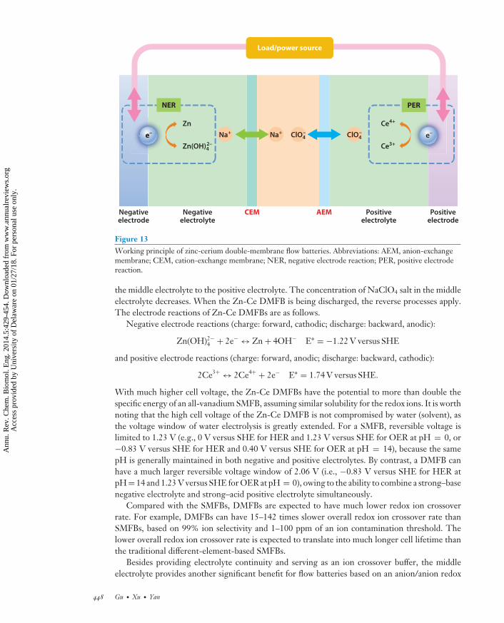
Figure 13Working principle of zinc-cerium double-membrane flow batteries. Abbreviations: AEM, anion-exchangemembrane; CEM, cation-exchange membrane; NER, negative electrode reaction; PER, positive electrodereaction.
the middle electrolyte to the positive electrolyte. The concentration of NaClO4 salt in the middleelectrolyte decreases. When the Zn-Ce DMFB is being discharged, the reverse processes apply.The electrode reactions of Zn-Ce DMFBs are as follows.
Negative electrode reactions (charge: forward, cathodic; discharge: backward, anodic):
Zn(OH)2−4 + 2e− ↔ Zn + 4OH− E◦ = −1.22 V versus SHE
and positive electrode reactions (charge: forward, anodic; discharge: backward, cathodic):
2Ce3+ ↔ 2Ce4+ + 2e− E◦ = 1.74 V versus SHE.
With much higher cell voltage, the Zn-Ce DMFBs have the potential to more than double thespecific energy of an all-vanadium SMFB, assuming similar solubility for the redox ions. It is worthnoting that the high cell voltage of the Zn-Ce DMFB is not compromised by water (solvent), asthe voltage window of water electrolysis is greatly extended. For a SMFB, reversible voltage islimited to 1.23 V (e.g., 0 V versus SHE for HER and 1.23 V versus SHE for OER at pH = 0, or−0.83 V versus SHE for HER and 0.40 V versus SHE for OER at pH = 14), because the samepH is generally maintained in both negative and positive electrolytes. By contrast, a DMFB canhave a much larger reversible voltage window of 2.06 V (i.e., −0.83 V versus SHE for HER atpH = 14 and 1.23 V versus SHE for OER at pH = 0), owing to the ability to combine a strong–basenegative electrolyte and strong–acid positive electrolyte simultaneously.
Compared with the SMFBs, DMFBs are expected to have much lower redox ion crossoverrate. For example, DMFBs can have 15–142 times slower overall redox ion crossover rate thanSMFBs, based on 99% ion selectivity and 1–100 ppm of an ion contamination threshold. Thelower overall redox ion crossover rate is expected to translate into much longer cell lifetime thanthe traditional different-element-based SMFBs.
Besides providing electrolyte continuity and serving as an ion crossover buffer, the middleelectrolyte provides another significant benefit for flow batteries based on an anion/anion redox
448 Gu · Xu · Yan
Ann
u. R
ev. C
hem
. Bio
mol
. Eng
. 201
4.5:
429-
454.
Dow
nloa
ded
from
ww
w.a
nnua
lrev
iew
s.or
g A
cces
s pr
ovid
ed b
y U
nive
rsity
of
Del
awar
e on
01/
27/1
8. F
or p
erso
nal u
se o
nly.

CH05CH20-Yan ARI 20 May 2014 19:27
pair versus a cation/cation pair: cleaning of crossed-over ion-contaminated electrolytes in negativeand positive electrolytes. Low-level crossed-over ions (e.g., 100 ppm) can be removed from thecontaminated electrolytes by refreshing the middle electrolytes, because the crossed-over ions willrapidly diffuse back to the fresh middle electrolytes under the established ion concentration dif-ference. Such a cleaning function helps drastically extend the cell lifetime. In addition, the middleelectrolyte could manage the possible water solvent–transfer issues among electrolytes by tuning itssalt concentration (a wide range of salt concentration in the middle electrolyte is allowed dependingon the state-of-charge swing) and its volume ratio to the negative electrolyte or positive electrolyte.
The double-membrane configuration is not limited to the Zn-Ce flow battery, and manyother redox pair combinations are possible. For example, an ultralow-cost sulfur-iron flow batterycombines the two highly available elements of iron and sulfur (first- and fifth-most-producedelements worldwide, respectively). Combining a S4
2−/S22− anion redox pair (−0.45 V versus SHE)
and Fe3+/Fe2+ cation redox pair (+0.77 V versus SHE), the sulfur-iron DMFB has the standard cellvoltage of 1.22 V (almost the same as the all-vanadium flow battery, 1.25 V). The high availabilityof electroactive elements endows the S-Fe flow battery with ultralow electrolyte cost.
Key Challenges of DMFBs
Durable electrodes and IEMs. With very high redox potential (1.74 V versus SHE ofCe4+/Ce3+), the Ce4+ ion is a strong oxidizing agent, and the electrode potential is even higherwhen the flow battery is being charged. Such a high electrode potential poses a significant chal-lenge for electrode materials (catalysts and substrates). Although carbon-based electrodes havebeen shown to have good activity for Ce4+/Ce3+ redox reaction, the long-term durability is still aserious concern, because carbon corrosion has very low potentials in acid (CO2/C, 0.21 V versusSHE and CO/C, 0.52 V versus SHE). Pt is stable and also active as an electrode material for theCe redox pair, but it is prohibitively expensive. Stable, active, and inexpensive electrode materialsare critically needed. Graphitic carbon materials, such as carbon nanotubes and graphenes, maybe suitable choices.
AEMs naturally repel cations, such as Ce4+ cations, from passing and crossing; however, AEMsare inevitably in contact with the highly concentrated Ce4+ environment, which also brings stabilityconcerns for AEMs against possible Ce4+ oxidization attack. Currently available flow-batteryAEMs are not specifically designed to work with such an oxidizing redox system (102, 103);therefore, novel AEMs with sufficient antioxidation ability are needed.
Low-resistance cell design. Compared with SMFBs, DMFBs have one more IEM and onemore electrolyte, leading to increased cell resistance. High cell resistance will cause low voltageefficiency at high current density. This is particularly serious for sulfur-iron DMFBs that haverelatively low reversible cell voltage and, thus, lower tolerance for voltage loss. Advanced celldesign is needed to effectively lower the overall cell resistance to maintain high voltage efficiency.Ultrathin chamber design, such as a membrane electrode assembly configuration, will help reducethe electrolyte resistance, and highly conductive and thin IEMs are also helpful to reduce mem-brane resistance. Flow channels should be optimized to facilitate mass transport, particularly inthe middle electrolyte, lowering the mass-transport resistance.
CONCLUDING REMARKS
Electrochemical energy conversion will be a leading path forward to a safe, clean, and sustainableenergy system in which the combustion of fossil fuels no longer dominates. FCs, ELs, SHs, and
www.annualreviews.org • Electrochemical Energy Engineering 449
Ann
u. R
ev. C
hem
. Bio
mol
. Eng
. 201
4.5:
429-
454.
Dow
nloa
ded
from
ww
w.a
nnua
lrev
iew
s.or
g A
cces
s pr
ovid
ed b
y U
nive
rsity
of
Del
awar
e on
01/
27/1
8. F
or p
erso
nal u
se o
nly.

CH05CH20-Yan ARI 20 May 2014 19:27
FBs are the foundation of such an electrochemical energy system, and this review discusses theirfundamental operating principles, technology development challenges, and materials researchopportunities. In particular, we call attention to the fact that the simple switch from an acid to abase polymer electrolyte, coupled with innovative cell design, could be a paradigm shift that leadsto a new generation of affordable electrochemical energy devices and their eventual commercialimplementation. Consistent with this recognition, much effort has been invested in the area ofAEMs and HEMs and their related devices, and many challenging problems have been solvedin the past five years. However, much work remains to be done before these devices can attainwidespread commercial deployment. To strengthen this research and to supply better-trainedresearchers, the formal introduction of electrochemical energy engineering as a subdiscipline ofchemical engineering will be of tremendous value. The incorporation of electrochemistry into theundergraduate and graduate curricula of chemical engineering programs is also a necessary andmuch-needed step.
DISCLOSURE STATEMENT
Y.S.Y. is a cofounder of OH-Energy Inc., which develops hydroxide exchange membrane fuelcells. S.G. and B.J.X. are not aware of any affiliations, memberships, funding, or financial holdingsthat might be perceived as affecting the objectivity of this review.
ACKNOWLEDGMENTS
The authors are grateful to the ARPA-E program of the US Department of Energy for its supportof the hydroxide exchange membrane fuel cell and redox flow battery work. We also thank theMURI program of the Department of Defense for supporting the synthesis of new cations for usein hydroxide exchange membranes.
LITERATURE CITED
1. Tobias CW. 1995. Interview by James J. Bohning. Chem. Herit. Found. Cent. Oral Hist., Orinda, CA.http://www.chemheritage.org/discover/collections/oral-histories/details/tobias-charles-w.aspx
2. Juda W, McRae WA. 1950. Coherent ion-exchange gels and membranes. J. Am. Chem. Soc. 72:1043–443. Grubb WT. 1959. Fuel cell. US Patent No. 2,913,5114. Wilson MS, Gottesfeld S. 1992. Thin-film catalyst layers for polymer electrolyte fuel-cell electrodes.
J. Appl. Electrochem. 22:1–75. Borup R, Meyers J, Pivovar B, Kim YS, Mukundan R, et al. 2007. Scientific aspects of polymer electrolyte
fuel cell durability and degradation. Chem. Rev. 107:3904–516. Bashyam R, Zelenay P. 2006. A class of non-precious metal composite catalysts for fuel cells. Nature
443:63–667. Wu G, More KL, Johnston CM, Zelenay P. 2011. High-performance electrocatalysts for oxygen reduc-
tion derived from polyaniline, iron, and cobalt. Science 332:443–478. Justi EW, Winsel AW. 1961. The DSK system of fuel cell electrodes. J. Electrochem. Soc. 108:1073–799. Agel E, Bouet J, Fauvarque JF. 2001. Characterization and use of anionic membranes for alkaline fuel
cells. J. Power Sources 101:267–7410. Varcoe JR, Slade RCT. 2005. Prospects for alkaline anion-exchange membranes in low temperature fuel
cells. Fuel Cells 5:187–20011. Lu SF, Pan J, Huang AB, Zhuang L, Lu JT. 2008. Alkaline polymer electrolyte fuel cells completely free
from noble metal catalysts. Proc. Natl. Acad. Sci. USA 105:20611–1412. Gu S, Sheng WC, Cai R, Alia SM, Song SQ, et al. 2013. An efficient Ag-ionomer interface for hydroxide
exchange membrane fuel cells. Chem. Commun. 49:131–33
450 Gu · Xu · Yan
Ann
u. R
ev. C
hem
. Bio
mol
. Eng
. 201
4.5:
429-
454.
Dow
nloa
ded
from
ww
w.a
nnua
lrev
iew
s.or
g A
cces
s pr
ovid
ed b
y U
nive
rsity
of
Del
awar
e on
01/
27/1
8. F
or p
erso
nal u
se o
nly.

CH05CH20-Yan ARI 20 May 2014 19:27
13. Varcoe JR, Slade RCT, Wright GL, Chen YL. 2006. Steady-state dc and impedance investigations ofH2/O2 alkaline membrane fuel cells with commercial Pt/C, Ag/C, and Au/C cathodes. J. Phys. Chem. B110:21041–49
14. Eisenberg D, Crothers D. 1979. Physical Chemistry with Applications to the Life Sciences. Menlo Park, CA:Benjamin Cummings Publ.
15. Isomura T, Fukuta K, Yanagi H, Ge SH, Wang CY. 2012. The effect of gas diffusion media on AMFCperformance. ECS Meet. Abstr. MA2012–02:1594
16. Yu EH, Wang X, Krewer U, Li L, Scott K. 2012. Direct oxidation alkaline fuel cells: from materials tosystems. Energy Environ. Sci. 5:5668–80
17. Ogumi Z, Matsuoka K, Chiba S, Matsuoka M, Iriyama Y, et al. 2002. Preliminary study on direct alcoholfuel cells employing anion exchange membrane. Electrochemistry 70:980–83
18. Fujiwara N, Siroma Z, Yamazaki SI, Ioroi T, Senoh H, Yasuda K. 2008. Direct ethanol fuel cells usingan anion exchange membrane. J. Power Sources 185:621–26
19. Matsuoka K, Iriyama Y, Abe T, Matsuoka M, Ogumi Z. 2005. Alkaline direct alcohol fuel cells using ananion exchange membrane. J. Power Sources 150:27–31
20. Yamada K, Yasuda K, Fujiwara N, Siroma Z, Tanaka H, et al. 2003. Potential application of anion-exchange membrane for hydrazine fuel cell electrolyte. Electrochem. Commun. 5:892–96
21. Lan R, Tao SW. 2010. Direct ammonia alkaline anion-exchange membrane fuel cells. Electrochem. Solid-St. Lett. 13:B83–B86
22. Fujiwara N, Yamazaki S, Siroma Z, Ioroi T, Senoh H, Yasuda K. 2009. Nonenzymatic glucose fuel cellswith an anion exchange membrane as an electrolyte. Electrochem. Commun. 11:390–92
23. McLean GF, Niet T, Prince-Richard S, Djilali N. 2002. An assessment of alkaline fuel cell technology.Int. J. Hydrog. Energy 27:507–26
24. Adams LA, Poynton SD, Tamain C, Slade RCT, Varcoe JR. 2008. A carbon dioxide tolerant aqueous-electrolyte-free anion-exchange membrane alkaline fuel cell. ChemSusChem 1:79–81
25. Fukuta K, Inoue H, Watanabe S, Yanagi H. 2009. In-situ observation of CO2 through the self-purgingin alkaline membrane fuel cell (AMFC). ECS Trans. 19:23–27
26. Pan J, Chen C, Zhuang L, Lu JT. 2012. Designing advanced alkaline polymer electrolytes for fuel cellapplications. Acc. Chem. Res. 45:473–81
27. Merle G, Wessling M, Nijmeijer K. 2011. Anion exchange membranes for alkaline fuel cells: a review.J. Membr. Sci. 377:1–35
28. Tang DP, Pan J, Lu SF, Zhuang L, Lu JT. 2010. Alkaline polymer electrolyte fuel cells: principle,challenges, and recent progress. Sci. China Chem. 53:357–64
29. Hickner MA. 2010. Ion-containing polymers: new energy & clean water. Mater. Today 13:34–4130. Zhang HW, Shen PK. 2012. Recent development of polymer electrolyte membranes for fuel cells. Chem.
Rev. 112:2780–83231. Couture G, Alaaeddine A, Boschet F, Ameduri B. 2011. Polymeric materials as anion-exchange mem-
branes for alkaline fuel cells. Prog. Polym. Sci. 36:1521–5732. Shevchenko VV, Gumennaya MA. 2010. Synthesis and properties of anion-exchange membranes for
fuel cells. Theor. Exp. Chem. 46:139–5233. Zhang HW, Shen PK. 2012. Advances in the high performance polymer electrolyte membranes for fuel
cells. Chem. Soc. Rev. 41:2382–9434. Jaeger W, Bohrisch J, Laschewsky A. 2010. Synthetic polymers with quaternary nitrogen atoms—
synthesis and structure of the most used type of cationic polyelectrolytes. Prog. Polym. Sci. 35:511–7735. Gu S, Cai R, Luo T, Chen ZW, Sun MW, et al. 2009. A soluble and highly conductive ionomer for
high-performance hydroxide exchange membrane fuel cells. Angew. Chem. Int. Ed. 48:6499–50236. Gu S, Cai R, Luo T, Jensen K, Contreras C, Yan YS. 2010. Quaternary phosphonium-based polymers
as hydroxide exchange membranes. ChemSusChem 3:555–5837. Gu S, Cai R, Yan YS. 2011. Self-crosslinking for dimensionally stable and solvent-resistant quaternary
phosphonium based hydroxide exchange membranes. Chem. Commun. 47:2856–5838. Zhang BZ, Gu S, Wang JH, Liu Y, Herring AM, Yan YS. 2012. Tertiary sulfonium as a cationic functional
group for hydroxide exchange membranes. RSC Adv. 2:12683–85
www.annualreviews.org • Electrochemical Energy Engineering 451
Ann
u. R
ev. C
hem
. Bio
mol
. Eng
. 201
4.5:
429-
454.
Dow
nloa
ded
from
ww
w.a
nnua
lrev
iew
s.or
g A
cces
s pr
ovid
ed b
y U
nive
rsity
of
Del
awar
e on
01/
27/1
8. F
or p
erso
nal u
se o
nly.

CH05CH20-Yan ARI 20 May 2014 19:27
39. Wang JH, Li SH, Zhang SB. 2010. Novel hydroxide-conducting polyelectrolyte composed of anpoly(arylene ether sulfone) containing pendant quaternary guanidinium groups for alkaline fuel cellapplications. Macromolecules 43:3890–96
40. Guo ML, Fang J, Xu HK, Li W, Lu XH, et al. 2010. Synthesis and characterization of novel anionexchange membranes based on imidazolium-type ionic liquid for alkaline fuel cells. J. Membr. Sci. 362:97–104
41. Zha YP, Disabb-Miller ML, Johnson ZD, Hickner MA, Tew GN. 2012. Metal-cation-based anionexchange membranes. J. Am. Chem. Soc. 134:4493–96
42. Gu S, Skovgard J, Yan YS. 2012. Engineering the van der Waals interaction in cross-linking-free hy-droxide exchange membranes for low swelling and high conductivity. ChemSusChem 5:843–48
43. Antolini E, Gonzalez ER. 2010. Alkaline direct alcohol fuel cells. J. Power Sources 195:3431–5044. Spendelow JS, Wieckowski A. 2007. Electrocatalysis of oxygen reduction and small alcohol oxidation in
alkaline media. Phys. Chem. Chem. Phys. 9:2654–7545. Blizanac BB, Ross PN, Markovic NM. 2007. Oxygen electroreduction on Ag(111): the pH effect. Elec-
trochim. Acta 52:2264–7146. Wang B. 2005. Recent development of non-platinum catalysts for oxygen reduction reaction. J. Power
Sources 152:1–1547. Chung HT, Won JH, Zelenay P. 2013. Active and stable carbon nanotube/nanoparticle composite
electrocatalyst for oxygen reduction. Nat. Commun. 4:192248. Suntivich J, May KJ, Gasteiger HA, Goodenough JB, Shao-Horn Y. 2011. A perovskite oxide optimized
for oxygen evolution catalysis from molecular orbital principles. Science 334:1383–8549. Suntivich J, Gasteiger HA, Yabuuchi N, Nakanishi H, Goodenough JB, Shao-Horn Y. 2011. Design
principles for oxygen-reduction activity on perovskite oxide catalysts for fuel cells and metal-air batteries.Nat. Chem. 3:546–50
50. Alia SM, Duong K, Liu T, Jensen K, Yan YS. 2012. Supportless silver nanowires as oxygen reductionreaction catalysts for hydroxide-exchange membrane fuel cells. ChemSusChem 5:1619–24
51. Wagner N, Schulze M, Gulzow E. 2004. Long term investigations of silver cathodes for alkaline fuelcells. J. Power Sources 127:264–72
52. Mamlouk M, Kumar SMS, Gouerec P, Scott K. 2011. Electrochemical and fuel cell evaluation of Cobased catalyst for oxygen reduction in anion exchange polymer membrane fuel cells. J. Power Sources196:7594–600
53. Mamlouk M, Wang X, Scott K, Horsfall JA, Williams C. 2011. Characterization and application of anionexchange polymer membranes with non-platinum group metals for fuel cells. Proc. Inst. Mech. Eng. A J.Power Energy 225:152–60
54. Kim J, Momma T, Osaka T. 2009. Cell performance of Pd-Sn catalyst in passive direct methanol alkalinefuel cell using anion exchange membrane. J. Power Sources 189:999–1002
55. Wu G, Cui GF, Li DY, Shen PK, Li N. 2009. Carbon-supported Co1.67Te2 nanoparticles as electro-catalysts for oxygen reduction reaction in alkaline electrolyte. J. Mater. Chem. 19:6581–89
56. Piana M, Boccia M, Filpi A, Flammia E, Miller HA, et al. 2010. H-2/air alkaline membrane fuelcell performance and durability, using novel ionomer and non-platinum group metal cathode catalyst.J. Power Sources 195:5875–81
57. Yanagi H, Fukuta K. 2008. Anion exchange membrane and ionomer for alkaline membrane fuel cells(AEMFCs). ECS Trans. 16:257–62
58. Pan J, Li Y, Zhuang L, Lu JT. 2010. Self-crosslinked alkaline polymer electrolyte exceptionally stableat 90◦C. Chem. Commun. 46:8597–99
59. Conway BE, Jerkiewicz G. 2000. Relation of energies and coverages of underpotential and overpotentialdeposited H at Pt and other metals to the ‘volcano curve’ for cathodic H2 evolution kinetics. Electrochim.Acta 45:4075–83
60. Sheng WC, Myint M, Chen JGG, Yan YS. 2013. Correlating the hydrogen evolution reaction activityin alkaline electrolytes with the hydrogen binding energy on monometallic surfaces. Energy Environ. Sci.6:1509–12
61. Sheng WC, Gasteiger HA, Shao-Horn Y. 2010. Hydrogen oxidation and evolution reaction kinetics onplatinum: acid versus alkaline electrolytes. J. Electrochem. Soc. 157:B1529–B36
452 Gu · Xu · Yan
Ann
u. R
ev. C
hem
. Bio
mol
. Eng
. 201
4.5:
429-
454.
Dow
nloa
ded
from
ww
w.a
nnua
lrev
iew
s.or
g A
cces
s pr
ovid
ed b
y U
nive
rsity
of
Del
awar
e on
01/
27/1
8. F
or p
erso
nal u
se o
nly.

CH05CH20-Yan ARI 20 May 2014 19:27
62. Barber J, Morin S, Conway BE. 1998. Specificity of the kinetics of H2 evolution to the structure ofsingle-crystal Pt surfaces, and the relation between OPD and UPD H. J. Electroanal. Chem. 446:125–38
63. Conway BE, Bai L. 1986. Determination of adsorption of OPD H species in the cathodic hydrogenevolution reaction at Pt in relation to electrocatalysis. J. Electroanal. Chem. 198:149–75
64. Alia SM, Pivovar BS, Yan Y. 2013. Platinum-coated copper nanowires with high activity for hydrogenoxidation reaction in base. J. Am. Chem. Soc. 135:13473–78
65. Strmcnik D, Uchimura M, Wang C, Subbaraman R, Danilovic N, et al. Improving the hydrogen oxida-tion reaction rate by promotion of hydroxyl adsorption. Nat. Chem. 5:300–6
66. Machado SAS, Avaca LA. 1994. The hydrogen evolution reaction on nickel surfaces stabilized by H-absorption. Electrochim. Acta 39:1385–91
67. Norskov JK, Bligaard T, Logadottir A, Kitchin JR, Chen JG, et al. 2005. Trends in the exchange currentfor hydrogen evolution. J. Electrochem. Soc. 152:J23–J26
68. Sleightholme AES, Varcoe JR, Kucernak AR. 2008. Oxygen reduction at the silver/hydroxide-exchangemembrane interface. Electrochem. Commun. 10:151–55
69. Tamain C, Poynton SA, Slade RCT, Carroll B, Varcoe JR. 2007. Development of cathode architecturescustomized for H2/O2 metal-cation-free alkaline membrane fuel. J. Phys. Chem. C 111:18423–30
70. Hagfeldt A, Boschloo G, Sun LC, Kloo L, Pettersson H. 2010. Dye-sensitized solar cells. Chem. Rev.110:6595–663
71. Nozik AJ, Beard MC, Luther JM, Law M, Ellingson RJ, Johnson JC. 2010. Semiconductor quantum dotsand quantum dot arrays and applications of multiple exciton generation to third-generation photovoltaicsolar cells. Chem. Rev. 110:6873–90
72. Gunes S, Neugebauer H, Sariciftci NS. 2007. Conjugated polymer-based organic solar cells. Chem. Rev.107:1324–38
73. Bergmann RB. 1999. Crystalline Si thin-film solar cells: a review. App. Phys. A. 69:187–9474. Denholm P, Margolis RM. 2007. Evaluating the limits of solar photovoltaics (PV) in electric power
systems utilizing energy storage and other enabling technologies. Energy Policy 35:4424–3375. Denholm P, Margolis RM. 2007. Evaluating the limits of solar photovoltaics (PV) in traditional electric
power systems. Energy Policy 35:2852–6176. Balzani V, Credi A, Venturi M. 2008. Photochemical conversion of solar energy. ChemSusChem 1:26–5877. Walter MG, Warren EL, McKone JR, Boettcher SW, Mi QX, et al. 2010. Solar water splitting cells.
Chem. Rev. 110:6446–7378. Fujishima A, Honda K. 1972. Electrochemical photolysis of water at a semiconductor electrode. Nature
238:37–3879. Maeda K, Teramura K, Lu DL, Takata T, Saito N, et al. 2006. Photocatalyst releasing hydrogen from
water—enhancing catalytic performance holds promise for hydrogen production by water splitting insunlight. Nature 440:295
80. Maeda K, Domen K. 2010. Photocatalytic water splitting: recent progress and future challenges. J. Phys.Chem. Lett. 1:2655–61
81. Maeda K, Higashi M, Lu DL, Abe R, Domen K. 2010. Efficient nonsacrificial water splitting through two-step photoexcitation by visible light using a modified oxynitride as a hydrogen evolution photocatalyst.J. Am. Chem. Soc. 132:5858–68
82. Moriya Y, Takata T, Domen K. 2013. Recent progress in the development of (oxy)nitride photocatalystsfor water splitting under visible-light irradiation. Coord. Chem. Rev. 257:1957–69
83. Linic S, Christopher P, Ingram DB. 2011. Plasmonic-metal nanostructures for efficient conversion ofsolar to chemical energy. Nat. Mater. 10:911–21
84. Spurgeon JM, Walter MG, Zhou JF, Kohl PA, Lewis NS. 2011. Electrical conductivity, ionic con-ductivity, optical absorption, and gas separation properties of ionically conductive polymer membranesembedded with Si microwire arrays. Energy Environ. Sci. 4:1772–80
85. Spurgeon JM, Lewis NS. 2011. Proton exchange membrane electrolysis sustained by water vapor. EnergyEnviron. Sci. 4:2993–98
86. Karakitsou K, Verykios XE. 1995. Definition of the intrinsic rate of photocatalytic cleavage of waterover Pt-RuO2/TiO2 catalysts. J. Catal. 152:360–67
www.annualreviews.org • Electrochemical Energy Engineering 453
Ann
u. R
ev. C
hem
. Bio
mol
. Eng
. 201
4.5:
429-
454.
Dow
nloa
ded
from
ww
w.a
nnua
lrev
iew
s.or
g A
cces
s pr
ovid
ed b
y U
nive
rsity
of
Del
awar
e on
01/
27/1
8. F
or p
erso
nal u
se o
nly.

CH05CH20-Yan ARI 20 May 2014 19:27
87. Yang ZG, Zhang JL, Kintner-Meyer MCW, Lu XC, Choi DW, et al. 2011. Electrochemical energystorage for green grid. Chem. Rev. 111:3577–613
88. Thaller LH. 1974. Electrically rechargeable redox flow cells. Proc. 9th Intersoc. Energy Convers. Eng. Conf.Proc., pp. 924–28. New York: Am. Soc. Mech. Eng.
89. Weber AZ, Mench MM, Meyers JP, Ross PN, Gostick JT, Liu QH. 2011. Redox flow batteries: a review.J. Appl. Electrochem. 41:1137–64
90. Skyllas-Kazacos M, Chakrabarti MH, Hajimolana SA, Mjalli FS, Saleem M. 2011. Progress in flowbattery research and development. J. Electrochem. Soc. 158:R55–R79
91. Wang W, Luo QT, Li B, Wei XL, Li LY, Yang ZG. 2013. Recent progress in redox flow battery researchand development. Adv. Funct. Mater. 23:970–86
92. Leung P, Li XH, de Leon CP, Berlouis L, Low CTJ, Walsh FC. 2012. Progress in redox flow batteries,remaining challenges and their applications in energy storage. RSC Adv. 2:10125–56
93. Remick RJ, Ang PGP. 1984. Electrically rechargeable anionically active reduction-oxidation electricalstorage-supply system. US Patent No. 4,485,154
94. Adams GB, Hollandsworth RP, Littauer EL. 1981. Proc. 16th Intersoc. Energy Convers. Eng. Conf., pp. 812–16. New York: Am. Soc. Mech. Eng.
95. Hruska LW, Savinell RF. 1981. Investigation of factors affecting performance of the iron-redox battery.J. Electrochem. Soc. 128:18–25
96. Skyllas-Kazacos M, Rychcik M, Robins RG, Fane AG, Green MA. 1986. New all-vanadium redox flowcell. J. Electrochem. Soc. 133:1057–58
97. Yamamura T, Watanabe N, Yano T, Shiokawa Y. 2005. Electron-transfer kinetics of Np3+/Np4+,NpO2
+/NpO22+, V2+/V3+, and VO2+/VO2
+ at carbon electrodes. J. Electrochem. Soc. 152:A830–3698. Hazza A, Pletcher D, Wills R. 2004. A novel flow battery: a lead acid battery based on an electrolyte
with soluble lead(II). Part I. Preliminary studies. Phys. Chem. Chem. Phys. 6:1773–7899. Yan YS, Gu S, Gong K. 2014. Double-membrane triple-electrolyte redox flow battery design. US Patent
Appl. No. 20140004402A1100. Yan YS, Gu S, Gong K. 2014. Multiple-membrane multiple-electrolyte redox flow battery design. US
Patent Appl. No. 20140004403A1101. Gu S, Gong K, Yan EZ, Yan Y. 2014. A multiple ion-exchange membrane design for redox flow batteries.
Energy Environ. Sci. In press. doi: 10.1039/C4EE00165F102. Schwenzer B, Zhang JL, Kim S, Li LY, Liu J, Yang ZG. 2011. Membrane development for vanadium
redox flow batteries. ChemSusChem 4:1388–406103. Li XF, Zhang HM, Mai ZS, Zhang HZ, Vankelecom I. 2011. Ion exchange membranes for vanadium
redox flow battery (VRB) applications. Energy Environ. Sci. 4:1147–60
454 Gu · Xu · Yan
Ann
u. R
ev. C
hem
. Bio
mol
. Eng
. 201
4.5:
429-
454.
Dow
nloa
ded
from
ww
w.a
nnua
lrev
iew
s.or
g A
cces
s pr
ovid
ed b
y U
nive
rsity
of
Del
awar
e on
01/
27/1
8. F
or p
erso
nal u
se o
nly.

ANNUAL REVIEWSConnect With Our Experts
New From Annual Reviews:Annual Review of Cancer Biologycancerbio.annualreviews.org • Volume 1 • March 2017
Co-Editors: Tyler Jacks, Massachusetts Institute of Technology Charles L. Sawyers, Memorial Sloan Kettering Cancer Center
The Annual Review of Cancer Biology reviews a range of subjects representing important and emerging areas in the field of cancer research. The Annual Review of Cancer Biology includes three broad themes: Cancer Cell Biology, Tumorigenesis and Cancer Progression, and Translational Cancer Science.
TABLE OF CONTENTS FOR VOLUME 1:• How Tumor Virology Evolved into Cancer Biology and
Transformed Oncology, Harold Varmus• The Role of Autophagy in Cancer, Naiara Santana-Codina,
Joseph D. Mancias, Alec C. Kimmelman• Cell Cycle–Targeted Cancer Therapies, Charles J. Sherr,
Jiri Bartek• Ubiquitin in Cell-Cycle Regulation and Dysregulation
in Cancer, Natalie A. Borg, Vishva M. Dixit• The Two Faces of Reactive Oxygen Species in Cancer,
Colleen R. Reczek, Navdeep S. Chandel• Analyzing Tumor Metabolism In Vivo, Brandon Faubert,
Ralph J. DeBerardinis• Stress-Induced Mutagenesis: Implications in Cancer
and Drug Resistance, Devon M. Fitzgerald, P.J. Hastings, Susan M. Rosenberg
• Synthetic Lethality in Cancer Therapeutics, Roderick L. Beijersbergen, Lodewyk F.A. Wessels, René Bernards
• Noncoding RNAs in Cancer Development, Chao-Po Lin, Lin He
• p53: Multiple Facets of a Rubik’s Cube, Yun Zhang, Guillermina Lozano
• Resisting Resistance, Ivana Bozic, Martin A. Nowak• Deciphering Genetic Intratumor Heterogeneity
and Its Impact on Cancer Evolution, Rachel Rosenthal, Nicholas McGranahan, Javier Herrero, Charles Swanton
• Immune-Suppressing Cellular Elements of the Tumor Microenvironment, Douglas T. Fearon
• Overcoming On-Target Resistance to Tyrosine Kinase Inhibitors in Lung Cancer, Ibiayi Dagogo-Jack, Jeffrey A. Engelman, Alice T. Shaw
• Apoptosis and Cancer, Anthony Letai• Chemical Carcinogenesis Models of Cancer: Back
to the Future, Melissa Q. McCreery, Allan Balmain• Extracellular Matrix Remodeling and Stiffening Modulate
Tumor Phenotype and Treatment Response, Jennifer L. Leight, Allison P. Drain, Valerie M. Weaver
• Aneuploidy in Cancer: Seq-ing Answers to Old Questions, Kristin A. Knouse, Teresa Davoli, Stephen J. Elledge, Angelika Amon
• The Role of Chromatin-Associated Proteins in Cancer, Kristian Helin, Saverio Minucci
• Targeted Differentiation Therapy with Mutant IDH Inhibitors: Early Experiences and Parallels with Other Differentiation Agents, Eytan Stein, Katharine Yen
• Determinants of Organotropic Metastasis, Heath A. Smith, Yibin Kang
• Multiple Roles for the MLL/COMPASS Family in the Epigenetic Regulation of Gene Expression and in Cancer, Joshua J. Meeks, Ali Shilatifard
• Chimeric Antigen Receptors: A Paradigm Shift in Immunotherapy, Michel Sadelain
ANNUAL REVIEWS | CONNECT WITH OUR EXPERTS
650.493.4400/800.523.8635 (us/can)www.annualreviews.org | [email protected]
ONLINE NOW!
Ann
u. R
ev. C
hem
. Bio
mol
. Eng
. 201
4.5:
429-
454.
Dow
nloa
ded
from
ww
w.a
nnua
lrev
iew
s.or
g A
cces
s pr
ovid
ed b
y U
nive
rsity
of
Del
awar
e on
01/
27/1
8. F
or p
erso
nal u
se o
nly.

CH05-FrontMatter ARI 5 May 2014 12:43
Annual Review ofChemical andBiomolecularEngineering
Volume 5, 2014 Contents
Plans and DetoursJames Wei � � � � � � � � � � � � � � � � � � � � � � � � � � � � � � � � � � � � � � � � � � � � � � � � � � � � � � � � � � � � � � � � � � � � � � � � � � � � � � � � � � � � � � 1
Simulating the Flow of Entangled PolymersYuichi Masubuchi � � � � � � � � � � � � � � � � � � � � � � � � � � � � � � � � � � � � � � � � � � � � � � � � � � � � � � � � � � � � � � � � � � � � � � � � � � � � � �11
Modeling Chemoresponsive Polymer GelsOlga Kuksenok, Debabrata Deb, Pratyush Dayal, and Anna C. Balazs � � � � � � � � � � � � � � � � � � �35
Atmospheric Emissions and Air Quality Impacts from Natural GasProduction and UseDavid T. Allen � � � � � � � � � � � � � � � � � � � � � � � � � � � � � � � � � � � � � � � � � � � � � � � � � � � � � � � � � � � � � � � � � � � � � � � � � � � � � � � � �55
Manipulating Crystallization with Molecular AdditivesAlexander G. Shtukenberg, Stephanie S. Lee, Bart Kahr,
and Michael D. Ward � � � � � � � � � � � � � � � � � � � � � � � � � � � � � � � � � � � � � � � � � � � � � � � � � � � � � � � � � � � � � � � � � � � � � �77
Advances in Mixed-Integer Programming Methods for ChemicalProduction SchedulingSara Velez and Christos T. Maravelias � � � � � � � � � � � � � � � � � � � � � � � � � � � � � � � � � � � � � � � � � � � � � � � � � � � � � �97
Population Balance Modeling: Current Status and Future ProspectsDoraiswami Ramkrishna and Meenesh R. Singh � � � � � � � � � � � � � � � � � � � � � � � � � � � � � � � � � � � � � � � � � � 123
Energy Supply Chain Optimization of Hybrid Feedstock Processes:A ReviewJosephine A. Elia and Christodoulos A. Floudas � � � � � � � � � � � � � � � � � � � � � � � � � � � � � � � � � � � � � � � � � � � 147
Dynamics of Colloidal Glasses and GelsYogesh M. Joshi � � � � � � � � � � � � � � � � � � � � � � � � � � � � � � � � � � � � � � � � � � � � � � � � � � � � � � � � � � � � � � � � � � � � � � � � � � � � � � 181
Rheology of Non-Brownian SuspensionsMorton M. Denn and Jeffrey F. Morris � � � � � � � � � � � � � � � � � � � � � � � � � � � � � � � � � � � � � � � � � � � � � � � � � � � 203
Factors Affecting the Rheology and Processability of HighlyFilled SuspensionsDilhan M. Kalyon and Seda Aktas � � � � � � � � � � � � � � � � � � � � � � � � � � � � � � � � � � � � � � � � � � � � � � � � � � � � � � � � � 229
vi
Ann
u. R
ev. C
hem
. Bio
mol
. Eng
. 201
4.5:
429-
454.
Dow
nloa
ded
from
ww
w.a
nnua
lrev
iew
s.or
g A
cces
s pr
ovid
ed b
y U
nive
rsity
of
Del
awar
e on
01/
27/1
8. F
or p
erso
nal u
se o
nly.

CH05-FrontMatter ARI 5 May 2014 12:43
Continuous-Flow Differential Mobility Analysis of Nanoparticlesand BiomoleculesRichard C. Flagan � � � � � � � � � � � � � � � � � � � � � � � � � � � � � � � � � � � � � � � � � � � � � � � � � � � � � � � � � � � � � � � � � � � � � � � � � � � 255
From Stealthy Polymersomes and Filomicelles to “Self”Peptide-Nanoparticles for Cancer TherapyNuria Sancho Oltra, Praful Nair, and Dennis E. Discher � � � � � � � � � � � � � � � � � � � � � � � � � � � � � � � 281
Carbon Capture Simulation Initiative: A Case Study in MultiscaleModeling and New ChallengesDavid C. Miller, Madhava Syamlal, David S. Mebane, Curt Storlie,
Debangsu Bhattacharyya, Nikolaos V. Sahinidis, Deb Agarwal, Charles Tong,Stephen E. Zitney, Avik Sarkar, Xin Sun, Sankaran Sundaresan, Emily Ryan,Dave Engel, and Crystal Dale � � � � � � � � � � � � � � � � � � � � � � � � � � � � � � � � � � � � � � � � � � � � � � � � � � � � � � � � � � � � 301
Downhole Fluid Analysis and Asphaltene Science for PetroleumReservoir EvaluationOliver C. Mullins, Andrew E. Pomerantz, Julian Y. Zuo, and Chengli Dong � � � � � � � � � � 325
Biocatalysts for Natural Product BiosynthesisNidhi Tibrewal and Yi Tang � � � � � � � � � � � � � � � � � � � � � � � � � � � � � � � � � � � � � � � � � � � � � � � � � � � � � � � � � � � � � � � 347
Entangled Polymer Dynamics in Equilibrium and Flow ModeledThrough Slip LinksJay D. Schieber and Marat Andreev � � � � � � � � � � � � � � � � � � � � � � � � � � � � � � � � � � � � � � � � � � � � � � � � � � � � � � � 367
Progress and Challenges in Control of Chemical ProcessesJay H. Lee and Jong Min Lee � � � � � � � � � � � � � � � � � � � � � � � � � � � � � � � � � � � � � � � � � � � � � � � � � � � � � � � � � � � � � � 383
Force-Field Parameters from the SAFT-γ Equation of State for Use inCoarse-Grained Molecular SimulationsErich A. Muller and George Jackson � � � � � � � � � � � � � � � � � � � � � � � � � � � � � � � � � � � � � � � � � � � � � � � � � � � � � � � 405
Electrochemical Energy Engineering: A New Frontier of ChemicalEngineering InnovationShuang Gu, Bingjun Xu, and Yushan Yan � � � � � � � � � � � � � � � � � � � � � � � � � � � � � � � � � � � � � � � � � � � � � � � � 429
A New Toolbox for Assessing Single CellsKonstantinos Tsioris, Alexis J. Torres, Thomas B. Douce,
and J. Christopher Love � � � � � � � � � � � � � � � � � � � � � � � � � � � � � � � � � � � � � � � � � � � � � � � � � � � � � � � � � � � � � � � � � � � 455
Advancing Adsorption and Membrane Separation Processes for theGigaton Carbon Capture ChallengeJennifer Wilcox, Reza Haghpanah, Erik C. Rupp, Jiajun He, and Kyoungjin Lee � � � � � 479
Toward the Directed Self-Assembly of Engineered TissuesVictor D. Varner and Celeste M. Nelson � � � � � � � � � � � � � � � � � � � � � � � � � � � � � � � � � � � � � � � � � � � � � � � � � � � 507
Ionic Liquids in Pharmaceutical ApplicationsI.M. Marrucho, L.C. Branco, and L.P.N. Rebelo � � � � � � � � � � � � � � � � � � � � � � � � � � � � � � � � � � � � � � � � � 527
Contents vii
Ann
u. R
ev. C
hem
. Bio
mol
. Eng
. 201
4.5:
429-
454.
Dow
nloa
ded
from
ww
w.a
nnua
lrev
iew
s.or
g A
cces
s pr
ovid
ed b
y U
nive
rsity
of
Del
awar
e on
01/
27/1
8. F
or p
erso
nal u
se o
nly.

CH05-FrontMatter ARI 5 May 2014 12:43
Perspectives on Sustainable Waste ManagementMarco J. Castaldi � � � � � � � � � � � � � � � � � � � � � � � � � � � � � � � � � � � � � � � � � � � � � � � � � � � � � � � � � � � � � � � � � � � � � � � � � � � � 547
Experimental and Theoretical Methods in Kinetic Studies ofHeterogeneously Catalyzed ReactionsMarie-Francoise Reyniers and Guy B. Marin � � � � � � � � � � � � � � � � � � � � � � � � � � � � � � � � � � � � � � � � � � � � � 563
Indexes
Cumulative Index of Contributing Authors, Volumes 1–5 � � � � � � � � � � � � � � � � � � � � � � � � � � � � � � 595
Cumulative Index of Article Titles, Volumes 1–5 � � � � � � � � � � � � � � � � � � � � � � � � � � � � � � � � � � � � � � � � 598
Errata
An online log of corrections to Annual Review of Chemical and Biomolecular Engineeringarticles may be found at http://www.annualreviews.org/errata/chembioeng
viii Contents
Ann
u. R
ev. C
hem
. Bio
mol
. Eng
. 201
4.5:
429-
454.
Dow
nloa
ded
from
ww
w.a
nnua
lrev
iew
s.or
g A
cces
s pr
ovid
ed b
y U
nive
rsity
of
Del
awar
e on
01/
27/1
8. F
or p
erso
nal u
se o
nly.