electrochemical dna biosensors - ecoli › ... › electrochemical_dna_biosensors.pdf · dna...
TRANSCRIPT

ELECTROCH
EMICA
L DN
A BIOSEN
SORS
ELECTROCHEMICAL DNA
B I O S E N S O R S
Edited by
Mehmet Ozsoz
Ozsoz
Mehmet Sengun Ozsoz is a professor of analytical chemistry in the Faculty of Pharmacy at Ege University and also teaches biosensor technology courses in the Biotechnology Department at Izmir Institute of Technology. Prof. Ozsoz holds a BS in chemical engineering from Middle East Technical University, Ankara, Turkey, and a PhD in analytical chemistry from the Faculty of Pharmacy, Ege University, Izmir, Turkey. He was a postdoctoral fellow with Dr Joseph Wang at New Mexico State University, Las Cruces, between 1989–1991 and 1996–1997. He is a recipient of
the 2008 Scientific and Technological Research Council of Turkey (TUBITAK) science award. Prof. Ozsoz conducts well-recognized international work on electrochemical DNA biosensors.
“The marriage of natural and synthetic nanotechnology in electrochemical DNA sensors is
a fascinating object of research. The reader gets an easy access to the complex matter by
the well-written introductory chapter. This volume builds a bridge from molecular biology
to the applications in medical diagnostics and microbiology.”
Prof. Frieder SchellerUniversität Potsdam, Germany
“This book is a very welcome contribution to the literature of electrochemical DNA
biosensors. It offers extremely useful insights into this exciting and important field.”
Dr. Joseph WangUniversity of California, San Diego, USA
This book focuses on the electrochemical applications of DNA in various areas, from basic
principles to the most recent discoveries. It comprises theoretical and experimental analyses
of various properties of nucleic acids, research methods, and some promising applications.
The topics discussed in the book include electrochemical detection of DNA
hybridization based on latex/gold nanoparticles and nanotubes; nanomaterial-
based electrochemical DNA detection; electrochemical detection of microorganism-
based DNA biosensor; gold nanoparticle-based electrochemical DNA biosensors;
electrochemical detection of the aptamer–target interaction; nanoparticle-induced
catalysis for DNA biosensing; basic terms regarding electrochemical DNA (nucleic
acids) biosensors; screen-printed electrodes for electrochemical DNA detection;
application of field-effect transistors to label-free electrical DNA biosensor arrays;
and electrochemical detection of nucleic acids using branched DNA amplifiers.

ELECTROCHEMICAL DNA
B I O S E N S O R S

This page intentionally left blankThis page intentionally left blank
Edited by
Mehmet Ozsoz
ELECTROCHEMICAL DNA
B I O S E N S O R S
CRC PressTaylor & Francis Group6000 Broken Sound Parkway NW, Suite 300Boca Raton, FL 33487-2742
© 2012 by Taylor & Francis Group, LLCCRC Press is an imprint of Taylor & Francis Group, an Informa business
No claim to original U.S. Government worksVersion Date: 20120410
International Standard Book Number-13: 978-9-81430-398-9 (eBook - PDF)
This book contains information obtained from authentic and highly regarded sources. Reason-able efforts have been made to publish reliable data and information, but the author and publisher cannot assume responsibility for the validity of all materials or the consequences of their use. The authors and publishers have attempted to trace the copyright holders of all material reproduced in this publication and apologize to copyright holders if permission to publish in this form has not been obtained. If any copyright material has not been acknowledged please write and let us know so we may rectify in any future reprint.
Except as permitted under U.S. Copyright Law, no part of this book may be reprinted, reproduced, transmitted, or utilized in any form by any electronic, mechanical, or other means, now known or hereafter invented, including photocopying, microfilming, and recording, or in any information storage or retrieval system, without written permission from the publishers.
For permission to photocopy or use material electronically from this work, please access www.copyright.com (http://www.copyright.com/) or contact the Copyright Clearance Center, Inc. (CCC), 222 Rosewood Drive, Danvers, MA 01923, 978-750-8400. CCC is a not-for-profit organiza-tion that provides licenses and registration for a variety of users. For organizations that have been granted a photocopy license by the CCC, a separate system of payment has been arranged.
Trademark Notice: Product or corporate names may be trademarks or registered trademarks, and are used only for identification and explanation without intent to infringe.
Visit the Taylor & Francis Web site athttp://www.taylorandfrancis.com
and the CRC Press Web site athttp://www.crcpress.com
March 14, 2012 18:57 PSP Book - 9in x 6in 00-Ozsoz–prelims
Contents
Preface xvii
1 Terminology Related to Electrochemical DNA-BasedBiosensors 1Jan Labuda1.1 Introduction 1
1.2 Detection Features of DNA-Based Biosensors 3
1.3 Detection of Specific DNA Interactions 7
1.3.1 DNA Hybridization Biosensors 7
1.3.2 DNA Damage 9
1.3.3 DNA Association Interactions 13
1.3.3.1 Binding of low molecular mass
compounds 13
1.3.3.2 Binding of proteins 14
1.4 Conclusions 15
2 Electrochemical Aptamer-Based Biosensors 29S. Centi, S. Tombelli, and M. Mascini
2.1 Introduction 29
2.2 Electrochemical Detection Strategies
Based on Labeling 31
2.3 Electrochemical Aptasensors Based on
a Sandwich Assay 32
2.4 Electrochemical Aptasensors Based on
a Competitive Assay 34
2.5 Electrochemical Aptasensors Based on a Direct
Assay 37
2.6 Electrochemical Metal Nanoparticle-Labeled
Aptasensors 39
March 14, 2012 18:57 PSP Book - 9in x 6in 00-Ozsoz–prelims
vi Contents
2.7 Electrochemical Aptasensors Based on Noncovalent
Redox Species Label 43
2.8 Electrochemical Aptasensors Based on the Aptamer
Conformational Changes 46
2.9 Electrochemical Aptasensors Based on
Target-Induced Aptamer Displacement 49
2.10 Conclusions 52
3 Carbon-Polymer Bio-Nano-Composite Electrodes forElectrochemical Genosensing 57Marıa Isabel Pividori and Salvador Alegret
3.1 Introduction 57
3.2 Composites Materials: Main Features and
Classification 61
3.3 Carbon Composites 65
3.3.1 Carbon-Based Materials as Conductive
Fillers in Composites 65
3.3.2 Rigid Carbon-Polymer Composite 69
3.3.3 Graphite-Epoxy Composites 71
3.4 Electrochemical Genosensing Based on
Graphite-Epoxy Composite 73
3.4.1 Electrochemical Genosensing Based on DNA
Dry Adsorption on GEC as Electrochemical
Transducer 73
3.4.2 Electrochemical Genosensing Based on DNA
Wet Adsorption on GEC as Electrochemical
Transducer 77
3.4.3 Electrochemical Genosensing Based on
Graphite-Epoxy Biocomposite Modified with
Avidin (Av-GEB) as Electrochemical
Transducer 78
3.4.4 Electrochemical Genosensing Based on
Magnetic Beads and m-GEC Electrochemical
Transducer 81
3.4.5 Electrochemical Genosensing Based on
Graphite-Epoxy Composite Modified with
Gold Nanoparticles (NanoAu-GEC) as
Electrochemical Transducer 87
3.5 Final Remarks 93
March 14, 2012 18:57 PSP Book - 9in x 6in 00-Ozsoz–prelims
Contents vii
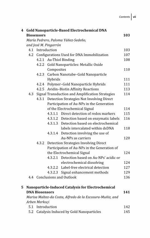
4 Gold Nanoparticle-Based Electrochemical DNABiosensors 103Marıa Pedrero, Paloma Yanez-Sedeno,and Jose M. Pingarron
4.1 Introduction 103
4.2 Configurations Used for DNA Immobilization 107
4.2.1 Au-Thiol Binding 108
4.2.2 Gold Nanoparticles: Metallic Oxide
Composites 110
4.2.3 Carbon Nanotube–Gold Nanoparticle
Hybrids 111
4.2.4 Polymer–Gold Nanoparticle Hybrids 111
4.2.5 Avidin–Biotin Affinity Reactions 113
4.3 Signal Transduction and Amplification Strategies 114
4.3.1 Detection Strategies Not Involving Direct
Participation of Au-NPs in the Generation
of the Electrochemical Signal 114
4.3.1.1 Direct detection of redox markers 115
4.3.1.2 Detection based on enzymatic labels 116
4.3.1.3 Detection based on electrochemical
labels intercalated within dsDNA 118
4.3.1.4 Detection involving the use of
Au-NPs as carriers 120
4.3.2 Detection Strategies Involving Direct
Participation of Au-NPs in the Generation of
the Electrochemical Signal 124
4.3.2.1 Detection based on Au-NPs’ acidic or
electrochemical dissolving 124
4.3.2.2 Label-free electrical detection 127
4.3.2.3 Signal enhancement methods 129
4.4 Conclusions and Outlook 136
5 Nanoparticle-Induced Catalysis for ElectrochemicalDNA Biosensors 141Marisa Maltez-da Costa, Alfredo de la Escosura-Muniz, andArben Merkoci
5.1 Introduction 142
5.2 Catalysis Induced by Gold Nanoparticles 145
March 14, 2012 18:57 PSP Book - 9in x 6in 00-Ozsoz–prelims
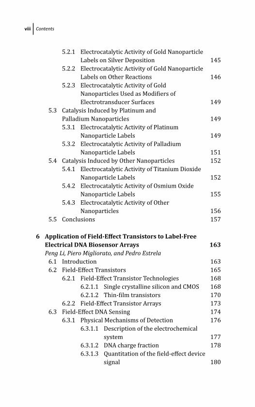
viii Contents
5.2.1 Electrocatalytic Activity of Gold Nanoparticle
Labels on Silver Deposition 145
5.2.2 Electrocatalytic Activity of Gold Nanoparticle
Labels on Other Reactions 146
5.2.3 Electrocatalytic Activity of Gold
Nanoparticles Used as Modifiers of
Electrotransducer Surfaces 149
5.3 Catalysis Induced by Platinum and
Palladium Nanoparticles 149
5.3.1 Electrocatalytic Activity of Platinum
Nanoparticle Labels 149
5.3.2 Electrocatalytic Activity of Palladium
Nanoparticle Labels 151
5.4 Catalysis Induced by Other Nanoparticles 152
5.4.1 Electrocatalytic Activity of Titanium Dioxide
Nanoparticle Labels 152
5.4.2 Electrocatalytic Activity of Osmium Oxide
Nanoparticle Labels 155
5.4.3 Electrocatalytic Activity of Other
Nanoparticles 156
5.5 Conclusions 157
6 Application of Field-Effect Transistors to Label-FreeElectrical DNA Biosensor Arrays 163Peng Li, Piero Migliorato, and Pedro Estrela
6.1 Introduction 163
6.2 Field-Effect Transistors 165
6.2.1 Field-Effect Transistor Technologies 168
6.2.1.1 Single crystalline silicon and CMOS 168
6.2.1.2 Thin-film transistors 170
6.2.2 Field-Effect Transistor Arrays 173
6.3 Field-Effect DNA Sensing 174
6.3.1 Physical Mechanisms of Detection 176
6.3.1.1 Description of the electrochemical
system 177
6.3.1.2 DNA charge fraction 178
6.3.1.3 Quantitation of the field-effect device
signal 180
March 14, 2012 18:57 PSP Book - 9in x 6in 00-Ozsoz–prelims
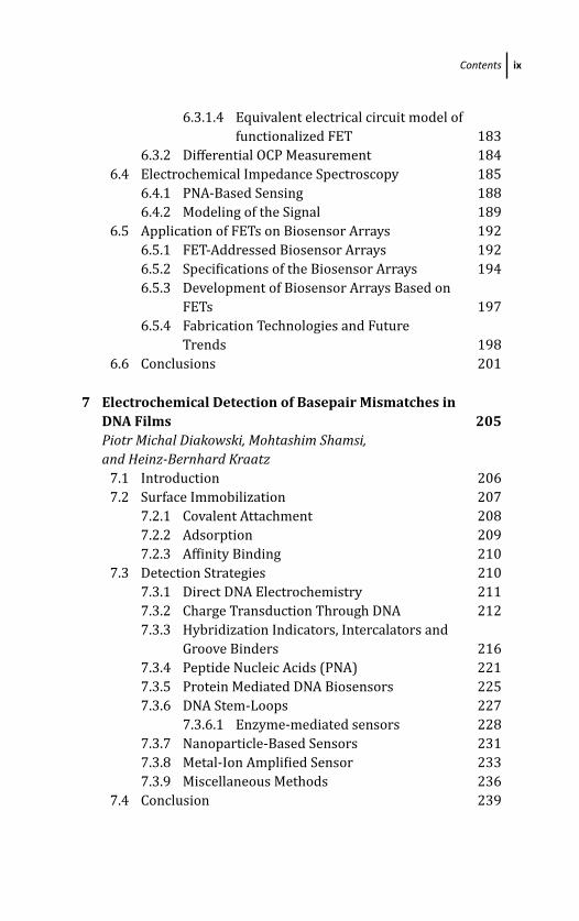
Contents ix
6.3.1.4 Equivalent electrical circuit model of
functionalized FET 183
6.3.2 Differential OCP Measurement 184
6.4 Electrochemical Impedance Spectroscopy 185
6.4.1 PNA-Based Sensing 188
6.4.2 Modeling of the Signal 189
6.5 Application of FETs on Biosensor Arrays 192
6.5.1 FET-Addressed Biosensor Arrays 192
6.5.2 Specifications of the Biosensor Arrays 194
6.5.3 Development of Biosensor Arrays Based on
FETs 197
6.5.4 Fabrication Technologies and Future
Trends 198
6.6 Conclusions 201
7 Electrochemical Detection of Basepair Mismatches inDNA Films 205Piotr Michal Diakowski, Mohtashim Shamsi,and Heinz-Bernhard Kraatz
7.1 Introduction 206
7.2 Surface Immobilization 207
7.2.1 Covalent Attachment 208
7.2.2 Adsorption 209
7.2.3 Affinity Binding 210
7.3 Detection Strategies 210
7.3.1 Direct DNA Electrochemistry 211
7.3.2 Charge Transduction Through DNA 212
7.3.3 Hybridization Indicators, Intercalators and
Groove Binders 216
7.3.4 Peptide Nucleic Acids (PNA) 221
7.3.5 Protein Mediated DNA Biosensors 225
7.3.6 DNA Stem-Loops 227
7.3.6.1 Enzyme-mediated sensors 228
7.3.7 Nanoparticle-Based Sensors 231
7.3.8 Metal-Ion Amplified Sensor 233
7.3.9 Miscellaneous Methods 236
7.4 Conclusion 239

March 14, 2012 18:57 PSP Book - 9in x 6in 00-Ozsoz–prelims
x Contents
8 Electrochemical Detection of DNA Hybridization: Useof Latex to Construct Metal-Nanoparticle Labels 245Mithran Somasundrum and Werasak Surareungchai
8.1 Introduction 245
8.2 Synthesis of Metal Nanoparticles 246
8.3 Use of Metal Nanoparticles as Electrochemical
Labels 249
8.4 Voltammetric Detection of Metal-Nanoparticle
Labels 254
8.4.1 Principles of Analytical Voltammetry 254
8.4.2 Anodic Stripping Voltammetry (ASV) 256
8.4.3 Quantification 258
8.4.3.1 Linear sweep voltammetry 258
8.4.3.2 Differential pulse voltammetry 260
8.4.3.3 Potentiometric stripping analysis 262
8.5 Latex as a Label Support 262
8.5.1 Introduction 262
8.5.2 Latex Synthesis 263
8.5.3 Latex Solution Properties 264
8.5.4 Layer-by-Layer Deposition: Theory 265
8.5.5 Layer-by-Layer Modification of Latex 267
8.5.5.1 Latex surface charge excess 267
8.6 DNA Measurement 278
8.6.1 DNA Immobilization 278
8.6.2 Probe Attachment 280
8.6.3 Detection Sequence 280
8.7 Areas for Further Research 284
9 Screen-Printed Electrodes for Electrochemical DNADetection 291Graciela Martınez-Paredes, Marıa Begona Gonzalez-Garcıa,and Agustın Costa-Garcıa
9.1 Introduction 292
9.2 Fabrication of Screen-Printed Electrodes 292
9.2.1 Types of Screen-Printed Electrodes 293
9.3 Genosensors on Screen-Printed Electrodes 294
9.3.1 Electrochemical Detection of Hybridization
Reaction 295
March 14, 2012 18:57 PSP Book - 9in x 6in 00-Ozsoz–prelims
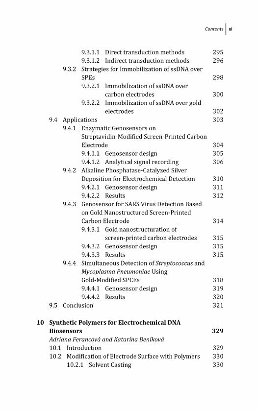
Contents xi
9.3.1.1 Direct transduction methods 295
9.3.1.2 Indirect transduction methods 296
9.3.2 Strategies for Immobilization of ssDNA over
SPEs 298
9.3.2.1 Immobilization of ssDNA over
carbon electrodes 300
9.3.2.2 Immobilization of ssDNA over gold
electrodes 302
9.4 Applications 303
9.4.1 Enzymatic Genosensors on
Streptavidin-Modified Screen-Printed Carbon
Electrode 304
9.4.1.1 Genosensor design 305
9.4.1.2 Analytical signal recording 306
9.4.2 Alkaline Phosphatase-Catalyzed Silver
Deposition for Electrochemical Detection 310
9.4.2.1 Genosensor design 311
9.4.2.2 Results 312
9.4.3 Genosensor for SARS Virus Detection Based
on Gold Nanostructured Screen-Printed
Carbon Electrode 314
9.4.3.1 Gold nanostructuration of
screen-printed carbon electrodes 315
9.4.3.2 Genosensor design 315
9.4.3.3 Results 315
9.4.4 Simultaneous Detection of Streptococcus and
Mycoplasma Pneumoniae Using
Gold-Modified SPCEs 318
9.4.4.1 Genosensor design 319
9.4.4.2 Results 320
9.5 Conclusion 321
10 Synthetic Polymers for Electrochemical DNABiosensors 329Adriana Ferancova and Katarına Benıkova10.1 Introduction 329
10.2 Modification of Electrode Surface with Polymers 330
10.2.1 Solvent Casting 330
March 14, 2012 18:57 PSP Book - 9in x 6in 00-Ozsoz–prelims
xii Contents
10.2.2 Spin Coating 330
10.2.3 Electropolymerization 331
10.3 Polymer-Assisted DNA Immobilization 332
10.3.1 Immobilization of DNA onto
Polymer-Modified Electrode Surface 332
10.3.2 Immobilization of DNA Within a Polymeric
Matrix by Electropolymerization 334
10.4 Application of Synthetic Polymers in DNA
Biosensors 334
10.4.1 Electronically (Intrinsically) Conducting
Polymers 334
10.4.1.1 Polypyrroles 335
10.4.1.2 Polyaniline 339
10.4.1.3 Polythiophene and its
derivatives 341
10.4.2 Redox Polymers 342
10.4.2.1 Quinone-containing polymers 342
10.4.2.2 Redox-active polymers
containing organometalic
redox center 343
10.4.3 Nonconducting Polymers 344
10.5 Conclusions 346
11 Electrochemical Transducer for OligonucleotideBiosensor Based on the Elimination and AdsorptiveTransfer Techniques 355Libuse Trnkova, Frantisek Jelen, and Mehmet Ozsoz11.1 Introduction 355
11.2 Theoretical Fundamentals of Elimination
Voltammetry with Linear Scan (EVLS) 356
11.2.1 Elimination Functions 356
11.2.2 EVLS of Adsorbed Species 359
11.2.3 Single and Double Mode of EVLS 360
11.3 EVLS Increasing the Transducer Potential
Range 362
11.4 EVLS in Connection with Adsorptive Stripping
Technique 362
11.4.1 AdS EVLS of Homo- and
Hetero-oligonucleotides 364
March 14, 2012 18:57 PSP Book - 9in x 6in 00-Ozsoz–prelims
Contents xiii
11.4.2 AdS EVLS of Hairpins 366
11.5 EVLS of Nucleobases and Oligonucleotides in the
Presence of Copper Ions 368
11.5.1 Mercury and Mercury-Modified
Electrodes 368
11.5.2 Solid Electrodes 371
11.6 Conclusions 373
12 Electrochemical DNA Biosensors for Detection ofCompound-DNA Interactions 379D. Ozkan-Ariksoysal, P. Kara, and M. Ozsoz12.1 Introduction 380
12.1.1 Aim of Electrochemical DNA Biosensors 380
12.2 The Structure of DNA 380
12.3 Natural Electronalytical Characterictics of DNA 383
12.4 Types of DNA Immobilization Methodologies onto
Sensor Surfaces 385
12.4.1 Adsorption (Wet Adsorption/Electrostatic
Accumulation) 386
12.4.2 Covalent Binding to Activated/
Nonactivated Surfaces 386
12.4.3 DNA Immobilization onto Transducer
Surfaces Via Avidin-Biotin Interaction 387
12.5 DNA-Compound Interactions 387
12.5.1 Types of Molecular Binding to DNA 388
12.5.1.1 Electrostatic interactions 388
12.5.1.2 Groove binding interactions 388
12.5.1.3 Intercalation mode 389
12.5.1.4 Specific binding for
single-stranded DNA 390
12.5.2 Detection Techniques for Compound-DNA
Binding Reactions Using Electrochemical
DNA Biosensors 390
12.5.2.1 Label-free detection based on
intrinsic DNA signals (direct
detection) 390
12.5.2.2 Compound-based detection
(indirect redox indicator-based
detection) 392
March 14, 2012 18:57 PSP Book - 9in x 6in 00-Ozsoz–prelims
xiv Contents
12.6 Calculations About Compound-DNA Interactions 394
12.7 Conclusions 395
13 Electrochemical Nucleic Acid Biosensors Based onHybridization Detection for Clinical Analysis 403P. Kara, D. Ariksoysal, and M. Ozsoz13.1 Introduction 403
13.2 Biosensors 404
13.2.1 Nucleic Acid Hybridization Biosensors 405
13.3 Electrochemical Nucleic Acid Biosensors 407
13.3.1 Label-Based Electrochemical Nucleic Acid
Biosensors 408
13.3.1.1 Electrochemical genosensing by
using hybridization indicator 408
13.3.1.2 Electrochemical genosensing
with labeled signaling probe or
labeled target DNA 414
13.3.2 Label-Free Electrochemical
Genosensing 415
13.4 Conclusion 420
14 Nanomaterial-Based Electrochemical DNA Detection 427Ronen Polsky, Jason C. Harper, and Susan M. Brozik14.1 Introduction 427
14.2 Nanoparticle-Based Electrochemical DNA
Detection 429
14.2.1 Nanoparticle Modification of Electrodes
and Their Use as Supports for DNA
Immobilization 429
14.2.2 Gold Nanoparticle Supports 430
14.2.3 Magnetic Particles 432
14.2.4 Layer-by-Layer Immobilization Techniques 434
14.2.5 Metal Nanoparticle Labels for DNA
Hybridization Detection 435
14.2.5.1 Direct detection of the
nanoparticle label 435
14.2.5.2 Non-stripping-based
nanoparticle electrochemical
DNA detection methods 440
March 14, 2012 18:57 PSP Book - 9in x 6in 00-Ozsoz–prelims
Contents xv
14.3 Nanowires, Nanorods, and Nanofibers 443
14.3.1 Nanorods as Labels 444
14.3.2 Nanowires Interfaced with Electrodes as
an Immobilization Matrix 445
14.3.3 Nanowire Conductance Based DNA
Detection 448
14.3.4 Electrochemical Impedance Spectroscopy
at Nanowires for DNA Detection 451
14.3.5 Dendrimers 452
14.3.6 Apoferritin Nanovehicles 455
14.3.7 Silica Nanoparticles 456
14.3.8 Liposomes 458
14.4 DNA Detection Using Carbon Nanotubes 461
14.4.1 Functionalization of Carbon Nanotubes
with DNA 462
14.4.2 CNTs for Electrochemical DNA Sensing 464
14.4.3 Progress toward CNT-Based Sensors for
DNA Detection 470
14.5 Conclusion 472
15 Electrochemical Genosensor Assay for the Detectionof Bacteria on Screen-Printed Chips 481Chan Yean Yean, Lee Su Yin, and Manickam Ravichandran15.1 Introduction 482
15.2 Methods for the Detection and Identification of
Microorganism Utilizing Enzyme-Based
Genosensors on Screen-Printed Chips 482
15.2.1 Electrochemical Genosensors for the
Detection of Bacteria 482
15.2.2 Principles of Enzyme-Based PCR
Amplicons Target DNA Detection
Methods 486
15.2.2.1 Direct method 486
15.2.2.2 Indirect method 488
15.2.2.3 Rapid method 488
15.2.3 Screen-Printed Transducer Surface 490
15.2.3.1 Screen-printed gold chip
genosensors 490
March 14, 2012 18:57 PSP Book - 9in x 6in 00-Ozsoz–prelims
xvi Contents
15.2.3.2 Screen-printed carbon-chip
genosensors 491
15.3 Advantages of the Enzyme-Based Electrochemical
Genosensors in Detecting Bacteria on
Screen-Printed Carbon Chips 492
15.4 Discussions 493
15.4 Conclusions 493
16 Introduction to Molecular Biology Related toElectrochemical DNA-Based Biosensors 499Yalcin Erzurumlu and Petek Ballar16.1 Introduction 499
16.2 Nucleic Acids 501
16.3 Deoxyribonucleic Acid 506
16.4 DNA in Electrochemical DNA-Based Biosensors 509
16.5 Nucleic Acid Variants Used in Electrochemical
DNA-Based Biosensors 511
16.5.1 Peptide Nucleic Acid (PNA) 511
16.5.2 Locked Nucleic Acid (LNA) 513
Index 517
March 14, 2012 18:57 PSP Book - 9in x 6in 00-Ozsoz–prelims
Preface
The discovery of DNA, the carrier of genetic information in cells,
brought with it many important technological accomplishments
such as the development of various diagnostic tools to unravel the
nature of hereditary diseases, gene expression profiling methods,
and genotyping. Among these, DNA biosensors constitute an
important class of point-of-care diagnostic devices because they
are capable of converting the Watson-Crick base pair recognition
event signal into an interpretable analytical signal in a shorter time
compared with other methods, thereby producing accurate and sen-
sitive results. Moreover, they are also suitable for miniaturization.
The terms “electrochemical DNA biosensor” and “nucleic acid–based
electrochemical biosensor” are used interchangeably.
By definition, biosensors are devices that fall into the subgroup of
biomedical sensors, combine a biological component with a detector
component, and are composed of three parts: (1) the biorecognition
element, such as an antibody, an enzyme, nucleic acids, or cell
lysates, which serves as a mediator; (2) the detector/transducer
element, which converts a biological signal into a readable output;
and (3) the signal processor, which displays a user-friendly version
of the transformed signal. Biosensors are classified according to
either the detector they are equipped with or the biorecognition
element they include. In general, the term “nucleic acid biosensors”
connotes devices that use single-stranded DNA as a biological
element. However, because of the advances in biosensor design, new
nucleic acid/nucleic acid analog interactions have been described
that are also considered to fall in this category, such as aptamer–
nucleic acid, RNA–DNA, peptide nucleic acid (PNA)–DNA, and locked
nucleic acid (LNA)–DNA. For the transduction of biological signals,
various kinds of detectors are available, but they can be categorized

March 14, 2012 18:57 PSP Book - 9in x 6in 00-Ozsoz–prelims
xviii Preface
into three main classes: optical, electrochemical, and piezoelectric.
Because electrochemical DNA biosensors are miniaturizable (i.e.,
reducible in size to nanoscale dimensions), fast, accurate, simple,
and low cost, they have played perhaps the greatest role in the fields
of molecular and medical diagnosis, environmental monitoring,
bioterrorism, food analysis, pharmacogenomics, and drug discovery.
The aim of this book is to cover the full scope of electrochemical
nucleic acid biosensors by emphazing on DNA detection. The
material is presented in 16 chapters. Starting with the terminology
related to electrochemical DNA–based biosensors in Chapter 1,
the researchers active in the fields of biosensor design, molecular
biology, and genetics describe types of detection used for analysis
(chapters 6, 9, 11, and 13), types of materials used for biosensor
design (chapters 3, 4, 5, 8, 10, and 14), and types of nucleic acid
interactions detected (chapters 2, 7, 12, and 15).
I hope that this state-of-the-art book will continue to inform and
inspire all levels of scientists for many years. I wish to express my
gratitude to the researchers throughout the world who contributed
to the book by sharing their valuable studies in the field of
biosensors. In their honor, I quote the amazing scientist Albert
Einstein: “Imagination is more important than knowledge.”
I would also like to thank my wife, Ayse, for her love and patience
as well as the editorial group of Pan Stanford Publishing for their
assistance and support.
Mehmet OzsozIzmir, Turkey
March 19, 2012 18:56 PSP Book - 9in x 6in 01-Ozsoz-c01
Chapter 1
Terminology Related to ElectrochemicalDNA-Based Biosensors
Jan LabudaInstitute of Analytical Chemistry, Slovak University of Technology in Bratislava,81237 Bratislava, [email protected]
1.1 Introduction
With respect to low costs and high detection/information effec-
tiveness, physical and chemical sensors help us today widely to
check and control more and more processes everywhere around
us. Biosensors were introduced to chemical sensors about 50 years
ago with the aim of utilizing the recognition ability of biological
components such as enzymes, antibodies, etc., for the detection
of species of interest. Among them, biosensors with electrical and
electrochemical transducers are most popular in development and
application due to general advantages of electroanalytical methods
such as rather simple sensor fabrication, low costs of equipment and
analysis, possibility of miniaturization, and automation in chemical
analysis. Techniques and terms of electroanalytical chemistry have
been reviewed in technical reports of the Union for Pure and Applied
Electrochemical DNA BiosensorsEdited by Mehmet OzsozCopyright c© 2012 Pan Stanford Publishing Pte. Ltd.ISBN 978-981-4241-77-9 (Hardcover), 978-981-4303-98-9 (eBook)www.panstanford.com
March 19, 2012 18:56 PSP Book - 9in x 6in 01-Ozsoz-c01
2 Terminology Related to Electrochemical DNA-Based Biosensors
Chemistry (IUPAC) titled “Classification and Nomenclature of Elec-
troanalytical” Techniques” [1], “Recommended Terms, Symbols, and
Definitions for Electroanalytical Chemistry” [2], and “Recommended
Terms, Symbols, and Definitions for Electroanalytical Chemistry
(Recommendations 1985)” [3] and in Compendium of AnalyticalNomenclature: The Orange Book [4]. Some special articles charac-
terize electrochemical sensors [5]. A special IUPAC technical report,
“Electrochemical Biosensors: Recommended Definitions and Clas-
sification” [6], deals with techniques and terms of electrochemical
biosensors.
Since the 1990s [7] deoxyribonucleic acid (DNA) has been, and
today a rather large scale of nucleic acids (NA) is being, utilized
as the biorecognition element at a new group of biosensors–so-
called DNA or generally nucleic acid biosensors (more exactly DNA-
based biosensors). Very recently, a new technical report of the IUPAC
under the title “Electrochemical Nucleic Acid-Based Biosensors:
Concepts, Terms and Methodology” has been prepared [8]. It
represents a critical classification of terms and techniques used in
this dynamically developing field. With respect to construction and
utilization of DNA-based biosensors, specific terminology is used
(often not uniformly) in literature. The aim of this chapter is to
present the terminology of electrochemical DNA-based biosensors
and frequently used terms in a glossary format.
The electrochemical DNA-based biosensor can be characterized
as a device that integrates DNA (generally a nucleic acid) as a
biological recognition element and an electrode as a physicochem-
ical transducer. It is often presented as an electrode chemically
modified by nucleic acid. The pioneering concept of an electrode
modified with the DNA layer has allowed a significant decrease in
the amount of DNA tested/determined [9]. Following the definition
of a chemically modified electrode [10, 11], this is true for thin
(<100 μm) DNA layer coverage. Depending on the way of biosensor
fabrication, thicker films of DNA occur on the electrode’s surface,
which is sometimes even not considered and reported.
The choice of electrode material is connected, on one hand,
with the electrochemical process of interest. DNA immobilization
at the electrode surface is an initial step that plays a major
role in the overall biosensor performance. Methods used vary
March 19, 2012 18:56 PSP Book - 9in x 6in 01-Ozsoz-c01
Detection Features of DNA-Based Biosensors 3
depending on the kind of transducer and biosensor application,
and detailed experimental conditions have to be optimized for each
special application. The role of transducers (working electrodes)
is fulfilled by bulk electrodes – typically mercury-based (mercury
film, mercury amalgam), carbon-based (glassy carbon, carbon paste,
graphite, graphite-epoxy composite), and some other (gold, indium
tin-oxide) electrodes, or by various thin- and thick-film electrodes
(e.g., screen-printed carbon and gold electrodes). DNA array sensors
utilize transducers realized with interdigitated electrode [12]. There
are also a variety of techniques used for DNA immobilization [13–
15]. Surface and also “bulk” phase of the electrodes have been
modified by DNA [16]. Measurements with electrochemical DNA
biosensors are mostly performed in voltammetric and chronopo-
tentiometric detection modes [17]. With general improvement in
impedimetric biosensors, electrochemical impedance spectroscopy
(EIS) has become popular as the measurement technique for DNA-
based biosensors [18, 19].
Electrochemical DNA-based biosensors and electrochemical
sensing (assay) without use of the true biosensor are sometimes
confused in the literature [8]. While in the electrochemical DNA
biosensor the DNA layer has to be in an intimate contact with the
electrode prior to and during the NA interaction with an analyte,
in electrochemical sensing the DNA itself or product of any DNA
interaction, which was performed in solution or even at another
solid surface (magnetic beads, etc.), is detected electrochemically,
usually after preconcentration by an accumulation on the electrode
surface.
1.2 Detection Features of DNA-Based Biosensors
DNA-based biosensors possess specificity of response, which is
typical for biosensors taking advantage of the bioaffinity properties
of DNA. Compared with enzyme sensors and immunosensors,
DNA biosensors are mostly used for the investigation of DNA
interactions rather than for conventional determination of the
concentration of an analyte. They exhibit typical biosensor selec-
tivity/specificity to the analyte (e.g., nucleotide bases sequence,
March 19, 2012 18:56 PSP Book - 9in x 6in 01-Ozsoz-c01
4 Terminology Related to Electrochemical DNA-Based Biosensors
protein) or class selectivity to DNA as the recognition element itself
(e.g., damage to DNA) [8]. With respect to this characteristic, DNA-
based biosensors represent irreplaceable testing (bio)analytical
devices.
Working procedures with these biosensors utilize special detec-
tion principles. In the first place, label-free techniques utilizing
electrochemical and/or surface activity of DNA have to be men-
tioned [17]. Electrochemical activity of DNA is based on the
presence of redox changes in nucleobases and sugar residues.
All common nucleobases are known to undergo electrochemical
oxidation at carbon electrodes. At neutral and weakly acidic pH,
adenine, cytosine, and guanine residues in DNA produce reduction
signals at mercury-based electrodes at highly negative potentials,
while guanine residues yield anodic signals due to oxidation of
their reduction product back to guanine. Protonation of base
residues is involved in the electrode process. Mercury electrodes are
particularly sensitive to minor conformational changes in DNA such
as those induced by nucleases and chemical and physical agents,
including ionizing radiation [17].
Nucleic acids are usually strongly adsorbed on electrodes,
particularly on mercury and carbon ones. For mercury electrodes,
the adsorption/desorption behavior of DNA strongly depends on
the structure of the DNA molecules. DNA electrochemical surface
activity depends on what DNA components take part in adsorption
at the electrode surface. The height of the tensammetric peak
increases with the chain length. Adsorption of DNA on mercury
electrodes proceeds only in one layer, and the formation of further
layers does not influence the intensity of electrochemical signals.
The polyanionic nature of nucleic acids leads to characteristic
adsorption/desorption (reorientation) processes at mercury-based
electrodes upon application of negative electrode potentials due
to interplay between electrostatic repulsion and relatively strong
adsorption via hydrophobic parts of the polynucleotide chains
(particularly bases) [13, 17]. Electrochemical analysis of the DNA
can, thus, in principle, be performed without introducing labels
into the DNA recognition element (label-free techniques) and even
without introducing any additional reagent into the measuring
system (reagent-less techniques).
March 19, 2012 18:56 PSP Book - 9in x 6in 01-Ozsoz-c01
Detection Features of DNA-Based Biosensors 5
As only guanine moieties in the close vicinity of the electrode
surface can undergo direct electrooxidation, soluble redox media-
tors such as rhodium or ruthenium complexes are sometimes used
to shuttle electrons from guanine residues in distant parts of DNA
chains to the electrode [20]. In such a case, we cannot speak more
about the reagent-less technique. Nevertheless, the electrochemical
reduction and oxidation of nucleobases are irreversible and thus do
not allow reusability of biosensors.
An alternative approach to the intrinsic DNA electrochemical
activity utilizes electroactive species as redox indicators of the
presence of immobilized DNA as well as its interaction events such
as hybridization, damage, and association with another substance
[14]. This mode was also used in a pioneering work on the DNA
biosensor used for sequence detection [7]. In this case, it is still a
label-free method in the sense that DNA probes or targets are not
chemically modified by a special label; however, as the indicator has
to be added to a test system as an additional reagent, we cannot
speak more about the reagent-less technique. Redox indicators
typically possess electrochemical responses at a “safe” electrode
potential and often reversibly. The terms redox probe and redoxmarker are sometimes used in the literature to mean the redox
indicator, which is confusable with the DNA capture probe used as
a recognition element at hybridization and with markers used in
medical diagnostics [8].
DNA redox indicators bind to DNA or are present in the
solution phase. Some of them interact with DNA on the basis of
electrostatic forces [21]. Cationic indicators such as metal complex
cations can be attracted to the DNA by the negative charge of
the DNA backbone. On the other hand, anionic indicators, for
instance hexacyanoferrate (III/II) [Fe(CN)6]3–/4–, work on the
principle of repulsion by the negatively charged DNA backbone. As
a consequence, its voltammetric current response is lower than and
anodic to the cathodic peak potential separation, higher than that
observed at bare electrodes without DNA. Electrostatic indicators
can also respond to differences in negative charge density between
ssDNA and dsDNA [14].
Other DNA redox indicators intercalate into the dsDNA structure
(e.g., daunomycin, phenoxazines, metal complexes with condensed

March 19, 2012 18:56 PSP Book - 9in x 6in 01-Ozsoz-c01
6 Terminology Related to Electrochemical DNA-Based Biosensors
aromatic heterocyclic ligands) or bind to dsDNA grooves (e.g.,
Hoechst 33258). All together, cationic indicators, intercalators, and
groove binders accumulate at the immobilized dsDNA layer (e.g.,
after hybridization or prior to damage to the DNA duplex), thus
increasing their measured voltammetric response. The biosensor
can be used repeatedly after its renewal using the sequence
of steps: indicator accumulation, voltammetric measurement and
chemical removal or desorption of the accumulated indicator
from the DNA layer. Then, for one and the same biosensor a
mean indicator response and its standard deviation are calculated
[21].
Indicators associating preferentially with ssDNA have been
advantageously used with electrochemical DNA hybridization sen-
sors. For instance, the phenothiazine dye methylene blue (MB) asso-
ciates with unpaired guanine moieties. In dsDNA this interaction
is hampered, which results in decrease in the current response
due to MB reduction [22]. On the other hand, there are also ds-
specific electroactive indicators such as the intercalator ferrocenyl
naphthalene diimide, which results in a detection limit of 10 zmol at
the differential pulse voltammetric mode [23, 24].
Finally, electrochemically active DNA labels (tracers), which are
covalently bound to DNA, can be used for detection. The DNA labels
considerably improve analytical selectivity/specificity, for instance,
at DNA hybridization as the labeled DNA can be distinguished
from the unlabeled one [17, 25]. Among such labels, ferrocene,
daunomycin, anthraquinone, thionine, bipyridine complexes of Ru
and Os, nitrophenyl, and aminophenyl groups have to be mentioned.
Osmium tetroxide complexes with nitrogen ligands (OsVIII,L) [26, 27]
or analogous osmate complexes (OsVI,L) [28] represent examples
of electroactive tags. Nanoparticles or nanocrystals of gold, indium,
zinc, cadmium, or lead chalcogenides and other materials have
been used as labels covalently (often via thiol linkage) attached
to DNA probes applied in amplifying the response. By combining
various nanoparticles such as ZnS, CdS, and PbS, electrochemical
“multicolor” DNA coding has been attained [29]. Carbon nanotubes
as DNA tags can also be loaded with multiple nanoparticles or
enzyme molecules, thus offering considerable signal enhancement
[22, 29, 30].
March 19, 2012 18:56 PSP Book - 9in x 6in 01-Ozsoz-c01
Detection of Specific DNA Interactions 7
1.3 Detection of Specific DNA Interactions
Among specific DNA interactions tested using DNA-based biosen-
sors, DNA hybridization, DNA association with low molecular mass
compounds (drugs, chemicals), and DNA damage are typically
considered.
1.3.1 DNA Hybridization Biosensors
DNA hybridization is a chemical interaction of DNA based on the
ability of ssDNA to form a helix, dsDNA with ssDNA counterpart
exhibiting nucleotide sequence complementarity. In DNA hybridiza-
tion biosensors, a specifically designed ssDNA probe (capture
probe [CP]) with a defined (known) nucleotide sequence is usually
immobilized on the electrode surface and allowed to interact as
a recognition element with target DNA (tDNA) in test solution.
By varying experimental conditions such as the pH, temperature,
and ionic strength, hybridization efficiency can be controlled, thus
allowing detection of single- or multi-base mismatches [15, 31].
Experimental arrangement for electrochemical DNA hybridiza-
tion biosensors includes the following:
1. Label-free and indicator (reagent)-less detection of target DNA
typically based on guanine residues response.
2. Noncovalent redox indicators that allow distinguishing between
the ssCP and dsDNA hybrid at the electrode surface (successful
hybridization) [22, 23].
3. Sandwich hybridization assay that employs a covalently labeled
reporter or signaling probe (RP) and involves two tDNA recogni-
tion steps (CP-tDNA and tDNA-RP) [32]. The RPs are designed to
hybridize with the tDNA at a site next to the sequence recognized
by the capture probe to confer efficient electronic communication
between the label and the electrode.
4. Peptide nucleic acid (PNA) probes as a DNA analogue that possess
an uncharged pseudopeptide backbone instead of the charged
phosphate-sugar backbone of natural DNA and, consequently,
greater affinity to complementary DNA and better distinction
between closely related sequences [33].

March 19, 2012 18:56 PSP Book - 9in x 6in 01-Ozsoz-c01
8 Terminology Related to Electrochemical DNA-Based Biosensors
Electrochemical biosensors of single nucleotide polymorphisms
(SNP, point mutations) can use
(i) different stabilities of duplexes displaying full complemen-
tarity between the probe and tDNA (homoduplexes between
wild-type probe and wild-type tDNA or mutant probe and
mutant target) and those involving mismatched nucleotides
(heteroduplexes between wild-type probe and mutant target,
or vice versa) [13]. Discrimination of perfectly matched and
mismatched duplexes can be achieved by performing DNA
hybridization at stringent conditions achieved by elevated
temperature and decreased ionic strength or via applying
a peptide nucleic acid probe instead of DNA. Under opti-
mum conditions, the homoduplex gives positive hybridization
response, while the heteroduplex is not stable, thus giving a
signal-off response to the mutation in one of the hybridizing
strands.
(ii) primer extension incorporation of a labeled nucleotide within
the SNP site [30]. The target template is annealed with a primer
complementary to the target segment “upstream” (relative to
DNA polymerase catalyzed elongation of the primer that always
proceeds in the 5’→3’ direction) to the position of interest, and
a labeled dNTP (e.g., with biotin to attach an enzyme in the
following step, or with a redox marker) is added to the reaction
mixture. Under proper conditions, the labeled nucleotide is
attached to the primer only when it is complementary to
the base at the first “free” position. Using different labels for
different nucleotides, all four possible bases within the SNP site
can be probed in a single reaction.
(iii) electronic properties of the duplex DNA and perturbations
in the DNA electronic properties in the presence of single
base mismatches [34]. Disruption of π -stacks within the DNA
double helix due to presence of the mismatch has been shown
to prevent DNA-mediated charge transfer between electrode
and an intercalator bound at the opposite (relative to the
electrode surface) end of the double helix, which was efficient
in the perfectly matched (and perfectly base-pair-stacked)
homoduplex.
March 19, 2012 18:56 PSP Book - 9in x 6in 01-Ozsoz-c01
Detection of Specific DNA Interactions 9
(iv) Electrochemical determination of the length of guanine-
containing triplet repeats was achieved by the mediator-based
guanine electrocatalytic oxidation technique. Other approaches
applied for this purpose involve multiple hybridization of a
labeled RP spanning several triplet units with the expanded
triplet repeat [25]. The number of RP molecules hybridized
(or labels collected) per tDNA strand is proportional to the
length of the repetitive sequence, which is – after proper
normalization to the number of target strands – reflected by
intensity of the measured signal.
1.3.2 DNA Damage
As DNA belongs to main body substrates that undergo serious
structural changes such as oxidation of the DNA bases and sugar
moieties and/or release of the bases as well as DNA strand breaks
caused by chemical systems generating so-called reactive oxygen
(ROS), nitrogen (RNS), or sulfur (RSS) species [35, 36] and by other
classes of genotoxic substances [37], the second main application
area of DNA-based biosensors is detection of damage to DNA. ROS
are produced endogenously, during normal aerobic metabolism
and under various pathological conditions, and exogenously, such
as upon exposure to UV light, ionizing radiation, environmental
mutagens, and carcinogens. About 104 to 106 DNA damage events
occur to a cell per day [37]. Accumulation of oxidative DNA lesions
is associated with aging and with a variety of human diseases,
including cancer and neurodegeneration. The terms DNA damage(see below) and mutation should not be intermingled. While
mutation refers to a change in DNA sequence, in damaged DNA
the chemical nature of individual nucleotides is changed, which can
result in mutation.
Altered chemical, physicochemical, and structural properties of
damaged DNA are reflected in its redox behavior, which is utilized
in numerous techniques of DNA damage detection. Electrochemical
DNA-based biosensors have been used not only to detect but also
to induce and control DNA damage at the electrode surface via
electrochemical generation of the damaging (usually radical) species
[13]. This way, chemicals and drugs such as niclosamide, adriamycin,
March 19, 2012 18:56 PSP Book - 9in x 6in 01-Ozsoz-c01
10 Terminology Related to Electrochemical DNA-Based Biosensors
benznidazole, thiophene-S-oxide, and nitroderivatives of polycyclic
aromatic compounds have been investigated [38–40].
Experimental arrangement for electrochemical DNA hybridiza-
tion biosensors includes the following:
(a) Label-free detection of strand breaks with mercury-based DNA
biosensors. These biosensors are based on strong dependence
of accessibility of DNA bases to the transducer surface (which
is lower at intact DNA compared with damaged DNA) and DNA
conformation (and/or local perturbations). Hence, mercury-
based DNA biosensors are able to discriminate between
DNA molecules containing (e.g., ssDNA) and lacking (e.g.,
sc plasmid DNA) free chain ends when free ends produce
specific electrochemical responses under certain conditions.
Nicking of supercoiled (sc) plasmid DNA with enzymes (such
as DNase I) as well as reactive radical species that destroy the
deoxyribose moieties, some types of nucleobase lesions after
their conversion to strand breaks by specific enzymes, and
repair of the strand breaks by action of the DNA ligases were
detected as well [13].
Detection of the sb at the hanging mercury drop electrode
(HMDE) is highly sensitive. By using alternating current (AC)
voltammetry, one sb was detected among more than 2 × 10⁵
nucleotides [41]. Although conventional HMDE possesses such
unique features, successful attempts have been made to replace
it by other electrodes in which the liquid mercury content would
be minimized or eliminated. Both redox and tensammetric DNA
signals have been measured at a mercury-film-coated solid
glassy carbon electrode (MF/GCE) and at different variants of
silver solid amalgam electrodes (AgSAE). MF/GCE [42], as well
as AgSAE and MF-AgSCE [43] modified with scDNA, was applied
to sb formation.
(b) Detection of DNA degradation at carbon-based biosensors
using redox indicators. Deep degradation of DNA during the
step of biosensor incubation for a given time (minutes to
hours) in a cleavage medium under investigation, after the
medium exchange for the follow-up electrochemical measure-
ment, results into diminution of the voltammetric response
March 19, 2012 18:56 PSP Book - 9in x 6in 01-Ozsoz-c01
Detection of Specific DNA Interactions 11
of the metal complex indicator that binds to DNA (such
as [Co(phen)3]3+ [14, 44–46]) or into enhancement of the
voltammetric response of the negatively charged metal complex
like [Fe(CN)6]3–/4–, which is repulsed by the negatively charged
DNA layer depending on the degree of DNA damage [47, 48].
Change in the indicator electrochemical response depends on
the portion of DNA damaged in the cleavage reaction. Similarly,
a decrease in the charge transfer resistance at an impedimetric
biosensor with hexacyanoferrate as the redox indicator in
solution was used [47, 48].
These types of DNA detection can also be applied to studies of
antioxidative properties of various natural substances preserv-
ing DNA from damage [49, 50]. The detection scheme exploits
quantification of the DNA portion that survives previous incu-
bation of the biosensor in a mixture of the DNA cleavage agent
and antioxidant/mixture of antioxidants under investigation.
Using this approach, yeast polysaccharides, phenolic acids such
as rosmarinic and caffeic acids, selected flavonoids, as well as
aqueous plant extracts and tea extracts were studied [51].
(c) Guanine residues’ redox responses [13, 14]. Among DNA base
residues, those of guanine not only possess electrochemical
response but are also the most frequent target for a range
of genotoxic agents. Consequently, the guanine residues’ redox
responses represent the most frequently used approach for
DNA damage detection. Decrease in the guanine peak current
relative to that yielded by undamaged DNA represents the
response to damage to the nucleobase and/or its release from
the polynucleotide chains, which is an event often following
modifications within the guanine imidazole ring. Since natural
DNA contains many guanine residues, partial decrease in the
guanine peaks is usually observed, depending on the extent of
DNA damage.
In contrast to analysis with HMDE, MFE, or AgSAE, measure-
ments of the guanine oxidation signal at carbon electrodes
(GCE, CPE, SPCE) cannot provide information about formation of
individual sb due to a lack of differences in the signal intensity
of sc and dsDNA (both oc and lin DNA that possess free ends)
but can be used for monitoring deep DNA degradation, involving
March 19, 2012 18:56 PSP Book - 9in x 6in 01-Ozsoz-c01
12 Terminology Related to Electrochemical DNA-Based Biosensors
damage to the guanine base and/or disintegration of DNA
molecules into small fragments [52]. With various biosensor
arrangements, effects of agents such as antitumor platinum
complexes [53] and various aromatic hydrocarbons derivatives
[54] on arsenic oxide [55] have been investigated using the
guanine response at the mercury-based electrodes. Besides
low specificity of this type of response, the general problem
of relatively low sensitivity is connected with the signal-off
approach.
(d) Detection of electroactive products of DNA damage. Some
products of DNA damage exhibit characteristic electrochemical
activity possessing a new signal. For example, 8-oxoguanine
(8-OG) is electrochemically oxidized at carbon electrodes at
a potential significantly less positive than the parent guanine
base [14, 38–40]. Compared with the previous one (described
under c), this approach exhibits much better sensitivity and
specificity. New species can be detected also using a redox
mediator. The complexes of osmium (such as [Os(bipy)3]3+) and
ruthenium with different redox potentials have been shown as
electrocatalysts for 8-OG and guanine, respectively [17, 56].
(e) Layered assemblies for genotoxicity screening. Multilayer
assemblies of cationic redox-active polymer films, DNA, and
heme proteins at carbon electrodes were designed for testing
the genotoxic activity of various chemicals [57]. In these devices,
layers of enzymatically active hemoproteins mimic metabolic
carcinogen activation processes (e.g., styrene is enzymatically
converted to styrene oxide). The activated species diffuse into
the DNA layer and attack guanine residues, and the damaged
DNA double helix is indicated by using guanine oxidation
mediated by a cationic polymeric film.
(f) A molecular beacon-like sensor for the evaluation of nuclease
and ligase activities. An electrochemical biosensor using a
hairpin DNA with an oxidizable ferrocene label was published
for the detection of activities of enzymes such as nucleases
(generating single-strand breaks) and DNA ligases (sealing the
break) [58]. At a single-strand break in the duplex part of the
hairpin structure, the ferrocene-labeled segment was removed
under conditions of danaturation with diminution of the current
March 19, 2012 18:56 PSP Book - 9in x 6in 01-Ozsoz-c01
Detection of Specific DNA Interactions 13
signal. In the presence of ligase activity, the break was joined,
preventing removal of the ferrocene-labeled segment.
1.3.3 DNA Association Interactions
1.3.3.1 Binding of low molecular mass compounds
DNA association interactions are of interest for chemistry, molecular
biology, and medicine, particularly for drug discovery and envi-
ronmental/medical processes [59, 60]. They concern association
with both inorganic and organic compounds as well as various
types of assisted interactions such as metal and metal complex–DNA
chemistry [61]. DNA-based biosensors serve as effective screening
tools for in vitro tests of this large group of DNA interactions.
Due to the preconcentration effect within the DNA structure, the
detection/concentration determination of a trace low molecular
mass analyte or group of analytes could also be a result of the study.
These noncovalent host–guest interactions are represented
mainly by [14]
(a) intercalation between the stacked base pairs of dsDNA,
(b) binding at major or minor grooves of the DNA double helix, and
(c) electrostatic interactions.
The intercalation as an insertion of guest molecules between
the stacked base pairs of the double helix structure leads to a
change in the dsDNA chain, which must lengthen and unwind
slightly. The intercalation can also have an influence on the
electrochemical activity of the intercalator. For instance, doxorubicin
and complexes of transient metals with 1,10-phenanthroline or
ferrocene naphthalene diimide retain their redox response after the
intercalation, but some others, e.g., phenothiazines, do not show
significant current signals after the intercalation. Sometimes the
intercalation can result in secondary interactions that can be used
for the detection, e.g., electron transfer from the guanine residues
(using, say, the [Ru(bpy)2]2+ complex), or generation of ROS able
to initiate oxidative cleavage of ribose cycles in the primary DNA
sequence.
March 19, 2012 18:56 PSP Book - 9in x 6in 01-Ozsoz-c01
14 Terminology Related to Electrochemical DNA-Based Biosensors
In contrast to intercalation, electrostatic interactions are formed
between positively charged guest molecules and the negatively
charged DNA sugar-phosphate backbone. However, depending on
the experimental conditions, these interaction modes can also be
combined [21]. For instance, the dsDNA interaction with positively
charged metal complex compounds with aromatic ligands is
predominantly electrostatic at low ionic strength and predominantly
intercalative at high ionic strength. The character of the binding
interaction of the components of electrically charged redox couples
(e.g., metal complexes) can be estimated from a net negative or
positive formal potential shift when the first one indicates the
stabilization of the component in a higher oxidation state over that
in a lower oxidation state, i.e., the electrostatic interaction, and the
second one can be ascribed to the intercalation [21, 62].
There are also compounds, particularly from the drug family (e.g.,
mitomycin C), that form covalent bonds with DNA bases and create
adducts yielding specific electrochemical responses [13].
The voltammetric response of association interaction relates
to an electrochemically active analyte, to an electrochemically
active species competing with analyte binding, or to guanine and
8-oxoguanine. Using an impedimetric DNA biosensor, distortion
of the surface-attached DNA can also be specified by appropriate
changes in the resistance of the charge transfer and capacity of the
surface layer. Impedimetric measurements provide also the possi-
bility of detecting electrochemically inactive analytes, which do not
bring about remarkable changes in the guanine oxidation current
[18, 19]. Recently, impedimetry performed in the presence of inter-
calators has been reported to specify the type of DNA interaction
[63].
1.3.3.2 Binding of proteins
Using DNA biosensors, two types of DNA–protein interactions can be
investigated: first, detection of catalytic activity of DNA-processing
enzymes such as nucleases, ligases, and polymerases; and second,
affinity interactions of DNA with proteins that can but need not be
enzymes. The detection techniques used can be the same as those
mentioned above for DNA hybridization sensors. Electroactivity of
March 19, 2012 18:56 PSP Book - 9in x 6in 01-Ozsoz-c01
Conclusions 15
amino acid residues in proteins allows for direct electrochemical
measurement without any labeling [64].
In specific cases, disturbance of the base pair stacking via flipping
out a nucleobase or via bending the duplex was found to affect the
dsDNA-mediated charge transfer at a gold electrode [65].
1.4 Conclusions
In this chapter, DNA-based biosensors were presented as special
analytical devices capable of selective or class-selective detec-
tion/recognition of chemical interactions of the surface-confined
DNA with substances of interest such as oligonucleotides, low
molecular mass compounds, and species leading to DNA damage
and preservation of DNA structure, together with related, rather
special terminology. As was stated for electrochemical biosensors
generally [6], definitions, terminology and classification cannot
unambiguously address every detail, nuance and contingency of this
diverse subject. This is also fully true for the rapidly developing
field of DNA-based biosensors with new forms of nucleic acids used;
new ways of sensor fabrication, measurement arrangement and
procedures; and finally new practical utilization. Nevertheless, the
terminology and classification presented here rather systematically
and documented by numerous examples could help build up
communication and understanding between experts and students in
this field.
We believe that it will also stimulate progress in the systematic
development of DNA biosensors and their application as screening
tools for drug investigation, as warning systems in rapid chemical
toxicity tests, as testing devices in food and water analysis, in
the evaluation of effects of antioxidants, and in the investigation
of interactions of nucleic acids with other biomacromolecules as
proteins.
Glossary
AC voltammetry/polarography An analysis of the current response
to a small-amplitude sinusoidal voltage perturbation superimposed
March 19, 2012 18:56 PSP Book - 9in x 6in 01-Ozsoz-c01
16 Terminology Related to Electrochemical DNA-Based Biosensors
on a DC (ramp or constant) potential [66]. A plot of the AC current
vs. sweep potential produces a derivative-type polarographic curve
[4].
Antioxidants Substances that at low concentrations than those
of an oxidizable biochemical substrate markedly delay or prevent
oxidation of this substrate [67]. Their behavior could be ascribed
to scavenging reactive radicals and chelation of redox-active metals,
particularly iron and copper. The most active and evaluated dietary
antioxidants belong to the family of phenolic and polyphenolic
compounds.
Antioxidative activity Complex parameter based on the (bio)
chemical reactivity of antioxidants. The antioxidative activity
belongs to characteristics typically defined operationally regarding
the procedure used. This applies to the utilization of DNA-based
biosensor as well.
Array electrodes Replacement of a single electrode (with dimen-
sions in the micrometer or centimeter range) by an array of
(ultra)microelectrodes [66].
Biological recognition system/biological receptor An element that
translates information from the biochemical domain, usually an
analyte concentration, into a chemical or physical output signal with
a defined sensitivity. The main purpose of the recognition system is
to provide the sensor with a high degree of selectivity for the analyte
to be detected [6].
Bases of nucleic acids Nitrogenous bases (purines such as adenine
and guanine or pyrimidines such as cytosine, thymine, and uracil).
Adenine, guanine, and cytosine are found in both deoxynucleotides
and ribonucleotides, whereas uracil is found primarily in ribonu-
cleotides, and thymine in deoxynucleotides.
Biosensor An integrated device incorporating a biological/
biomimetic recognition system either integrated within or inti-
mately associated with a physicochemical transducer [68]. Biosen-
sors are chemical sensors in which the recognition system utilizes a
biochemical mechanism [6].
March 19, 2012 18:56 PSP Book - 9in x 6in 01-Ozsoz-c01
Glossary 17
Capture probe (CP) A specifically designed ssDNA with a defined
(known) nucleotide sequence usually immobilized on a transducer
or other surface. The CP is utilized as a recognition element to test
nucleotide sequence of target DNA (tDNA) in the sample solution by
using hybridization.
Chemical sensor A device that converts chemical information
such as the presence/concentration of specific sample components
into a measurablel signal [66]. Chemical sensors contain two basic
functional units connected in a series: a chemical (molecular)
recognition system (receptor) and a physicochemical transducer
[6]. It is capable of continuously recognizing the presence and/or
concentration of a chemical constituent in a liquid or gas and
converting this information in real time to an electrical or optical
signal.
Chemically modified electrode An electrode made of a conduct-
ing or semiconducting material that is coated with a selected
monomolecular, multimolecular, ionic, or polymeric film of a
chemical modifier and that by means of faradaic (charge transfer)
reactions or interfacial potential differences (no net charge transfer)
exhibits chemical, electrochemical, and/or optical properties of
the film [10, 11]. The chemically altered bare (working) electrode
exhibits new qualities concerning selectivity and sensitivity as well
as against fouling and interferences.
Circular DNA A structure of DNA when its double-helical segment
is closed to a circle by joining its two ends.
DNA (deoxyribonucleic acid) A polyanionic biopolymer consisting
of a chain of nucleotides linked with phosphates bridge at the 3’ and
5’ positions of neighboring sugar (2-deoxyribose) units (ssDNA).
Complementary base pairing results in the specific association of
two polynucleotide chains that wind around a common helical axis
to form a double helix (dsDNA).
DNA-based biosensor A biosensor that uses DNA as the biorecog-
nition element.
March 19, 2012 18:56 PSP Book - 9in x 6in 01-Ozsoz-c01
18 Terminology Related to Electrochemical DNA-Based Biosensors
DNA biosensor In general, a biosensor used for detection of DNA
and/or its specific interactions. It is mostly represented by a DNA-
based biosensor.
DNA damage Alteration in the DNA chemical structure resulting
from interactions with physical or chemical agents occurring in
the environment, generated in the organisms as by-products of
metabolism or used as therapeutics [13]. The main types of DNA
damage include interruptions of the sugar-phosphate backbone
(strand breaks), release of bases due to hydrolysis of N-glycosidic
bonds (resulting in abasic sites), and a variety of nucleobase lesions
(adducts) resulting from reactions of DNA with a broad range of
oxidants, alkylating agents, and others.
DNA hybridization Chemical interaction of DNA based on the
ability of ssDNA to form a helix, dsDNA with a counterpart exhibiting
nucleotide sequence complementarity. A process of the formation of
dsDNA from ss polynucleotide chains based on complementary base
pairing.
DNA label (tracer) Species covalently bound to DNA and used in its
electrochemical detection.
Electrochemical biosensor A self-contained integrated device that
is capable of providing specific quantitative or semiquantitative
analytical information using a biological recognition element (bio-
chemical receptor), which is retained in direct spatial contact with
an electrochemical transduction element [6]. A biosensor with an
electrochemical transducer may represent a chemically modified
electrode.
Electrochemical DNA-based biosensor A biosensor that integrates
DNA (generally a nucleic acid) as the biological recognition element
and an electrode as the physicochemical transducer.
Electrochemical cell/voltammetric cell A cell where electrochemi-
cal/voltammetric measurements are performed. It incorporates an
ionic conductor (electrolyte, sample solution) and typically three
electrodes: a working electrode (a microelectrode), a current-
March 19, 2012 18:56 PSP Book - 9in x 6in 01-Ozsoz-c01
Glossary 19
conducting electrode (auxiliary or counterelectrode), and a refer-
ence electrode.
Electrochemical impedance spectroscopy A technique based on
evaluation of the interfacial impedance, which is obtained upon
application of a small AC voltage overlaid on a DC bias potential to
the sensing (working) electrode and measurement of the AC current
obtained in the steady state.
Electrode/working electrode In general, an electrode that serves
as a transducer responding to the excitation signal and the
concentration of the substance of interest in the solution being
investigated, and that permits the flow of current sufficiently large to
effect appreciable changes of bulk composition within the ordinary
duration of a measurement [2–4]. In electrochemical analysis, differ-
ent working electrodes are used, e.g., dropping mercury electrode
(DME) (typically in polarography), static mercury drop electrode
(SMDE), or solid electrodes (in voltammetry and other electroana-
lytical techniques). In electrochemical sensors/biosensors, suitable
working electrodes are used as physicochemical transducers that
convert a biological recognition event into a measurable signal.
Groove binding Binding of a guest molecule, typically of a moon-
shaped and flat in structure, into the exterior of the DNA helix.
Impedimetric DNA biosensor A DNA biosensor based on electro-
chemical impedance spectroscopy (EIS) detection. It is a device
that transduces changes in interfacial properties between the
electrode (with the DNA film) and the electrolyte induced by
DNA hybridization, conformational changes, or DNA damages to an
electrical signal [19].
Immobilization A method that can immobilize a biological receptor
with high biological activity in a thin layer at the transducer surface.
It is a step in biosensor fabrication.
Intercalation Insertion of a guest molecule between the base pairs
of the DNA helix.
March 19, 2012 18:56 PSP Book - 9in x 6in 01-Ozsoz-c01
20 Terminology Related to Electrochemical DNA-Based Biosensors
Intercalator A compound that undergoes intercalation, typically a
molecule with a planar structure containing three or four aromatic
rings.
Label-free detection technique Procedure that utilizes electro-
chemical and/or surface activity of DNA (reduction and tensammet-
ric responses of DNA at mercury and some amalgam electrodes,
guanine oxidation at carbon electrodes, detection by using nonco-
valent DNA redox indicators, etc.). The label-free technique uses no
chemical modification of a DNA probe or target or another analyte
interacting with NA.
Microelectrode/ultramicroelectrode An electrode with a char-
acteristic dimension ranging from 25 μm to 1 mm [66]. An
ultramicroelectrode has a characteristic dimension less than 25 μm.
This characteristic dimension refers to the diameter of a disk, a
sphere, a hemisphere, and a cylinder, and the width of a band
ultramicroelectrode.
Nucleic acid aptamers Single-stranded oligonucleotides (mainly
DNA or RNA) originating from in vitro selection that, starting
from random sequence libraries, optimize the nucleic acids for
high-affinity binding to a given target [69, 70]. Aptamers, upon
association with their target, fold into complex three-dimensional
shapes in which the target becomes an intrinsic part of the nucleic
acid structure.
Nucleobase lesion A chemical modification of nucleobase, e.g., its
oxidative change.
Nucleotide A molecule composed of a nitrogenous base (purine or
pyrimidine) linked to a sugar (deoxyribose or ribose) to which at
least one phosphate group is attached.
Nucleoside A molecule composed of a nitrogenous base (purine or
pyrimidine) linked to a sugar (deoxyribose or ribose).
8-oxoguanine (8-OG) The oxidation product of guanine, which can
be electrochemically oxidized at carbon electrodes at a potential
significantly less positive than the parent guanine base.
March 19, 2012 18:56 PSP Book - 9in x 6in 01-Ozsoz-c01
Glossary 21
Physicochemical electrochemical transducers See Electrode/workingelectrode
Reagent-less detection technique A procedure that uses no addi-
tional chemical reagents (indicator, redox mediator, enzyme sub-
strate) to generate an analytical signal of the DNA biosensor.
Redox reaction A chemical reaction in which the reactants
exchange electrons between each other. As a consequence, the
oxidation states of the elements prior to and following the redox
reaction are altered [66].
Electrode reaction An interfacial reaction that necessarily involves
a charge transfer step [66] between a chemical reactant (depolar-
izer) and the electrode (an electrochemical reaction). The electrode
reaction involves all processes (chemical reaction, structural reorga-
nization, adsorption) accompanying the charge transfer step.
Redox mediator A chemical compound that can shuttle electrons
between two other chemical compounds in solution or between an
electrode and a chemical species in solution [66].
Screen-printed electrode An electrode prepared by forced screen
printing of a powder-based ink through a screen stencil typically
on a plastic sheet or foil, or ceramic plate, as a single or set of film
electrodes [66].
Selectivity of the DNA-based biosensor It can be truely considered
as an analytical parameter regarding the analyte detected such as
a specific ssDNA base sequence or protein interacting with nucleic
acid aptamer. Generally, class selectivity to DNA as the recognition
element itself can be considered (e.g., at damage to DNA).
Signal-on/signal-off measurement technique A procedure based
on appearance/diminution of analytical response resulting from
molecular interaction at the biosensor.
Single-/multi-base mismatch A defect in the double-stranded DNA
structure that distinguishes DNA hybrid containing a mismatched
base pair or pairs from that with fully matched bases.
March 19, 2012 18:56 PSP Book - 9in x 6in 01-Ozsoz-c01
22 Terminology Related to Electrochemical DNA-Based Biosensors
Single nucleotide polymorphisms (SNPs, point mutations) A
variant of DNA sequence in which the purine or pyrimidine base (as
cytosine) of a single nucleotide is replaced by another such base (as
thymine). It is the most common type of change in DNA. SNPs occur
normally throughout a person’s DNA once in every 300 nucleotides
on average, which means there are roughly 10 million SNPs in the
human genome. They can act as biological markers.
Strand break An interruption of the sugar-phosphate backbone of
the nucleotide.
Supercoiled DNA A contortion of circular DNA into the shape
of the simple figure eight. DNA supercoiling is important for DNA
packaging within all cells.
Tensammetry Measurement of the interfacial capacitance as a
function of potential. It is used especially in the analysis of surface-
active substances that are not electroactive [66].
Transducer Part of the sensor/biosensor that converts a detected
physical or chemical change into a measurable (usually electronic)
signal. Working electrodes are used as transducers in electrochemi-
cal biosensors.
Voltammetry/polarography Measurement of current as a function
of a controlled electrode potential and time, which results in a
current–voltage (or current–time or current–voltage–time) display,
commonly referred to as the “voltammogram” [66]. The working
electrode is situated typically in the voltammetric cell and is a
dropping mercury electrode in the case of polarography.
List of abbreviations
AC alternating current
AgSAE silver solid amalgam electrode
CNTs carbon nanotubes
CP capture probe
CPE carbon paste electrode
DC direct current
March 19, 2012 18:56 PSP Book - 9in x 6in 01-Ozsoz-c01
References 23
DME dropping mercury electrode
DNase deoxyribonuclease
dNTP deoxynucleotide triphosphate
ds double stranded
dsDNA double-stranded DNA
EIS electrochemical impedance spectroscopy
GCE glassy carbon electrode
HMDE hanging mercury drop electrode
L ligand
lin linear
MB methylene blue
MFE mercury film electrode
oc open circular
8-OG 8-oxoguanine
ODN oligodeoxyribonucleotide
PCR polymerase chain reaction
PNA peptide nucleic acid
RNS reactive nitrogen species
ROS reactive oxygen species
RSS reactive sulfur species
RP reporter probe
SMDE static mercury drop electrode
SNP single-nucleotide polymorphisms
SPE screen-printed electrode
SPCE screen printed carbon electrode
sb strand break
sc supercoiled
ss single stranded
ssDNA single-stranded DNA
ssb single-strand break
tDNA target DNA
UV ultraviolet
References1. L. Meites, H. W. Nurnberg, and P. Zuman, Pure Appl. Chem. 45, 81–97
(1976).
2. L. Meites, Pure Appl. Chem. 51, 1159–1174 (1979).
March 19, 2012 18:56 PSP Book - 9in x 6in 01-Ozsoz-c01
24 Terminology Related to Electrochemical DNA-Based Biosensors
3. L. Meites, P. Zuman, and H. W. Nurnberg, Pure Appl. Chem. 57, 1491–
1505 (1985).
4. Compendium of Analytical Nomenclature: The Orange Book, 3rd ed.,
(J. Inczedy, T. Lengyel, A. M. Ure, eds.), Blackwell Science (1998).
5. C. M. A. Brett, Pure Appl. Chem. 73, 1969–1977 (2001).
6. D. R. Thevenot, K. Toth, R. A. Durst, and G. S. Wilson, Pure Appl. Chem. 71,
2333–2348 (1999).
7. K. M. Millan and S. R. Mikkelsen, Anal. Chem. 65, 2317–2323 (1993).
8. J. Labuda, A. M. O. Brett, G. Evtugyn, M. Fojta, M. Mascini, M. Ozsoz,
I. Palchetti, E. Palecek, and J. Wang, Pure Appl. Chem. 82, 1161–1187
(2010). DOI: 10.1351/PAC-REP-09-08-16.
9. E. Palecek, and I. Postbieglova, J. Electroanal. Chem. 214, 359 (1986).
10. R. A. Durst, A. J. Baumner, R. W. Murray, R. P. Buck, and C. P. Andrieux,
Pure Appl. Chem. 69, 1317–1324 (1997).
11. W. Kutner, J. Wang, M. L’Her, and R. P. Buck, Pure Appl. Chem. 70, 1301–
1318 (1998).
12. A. Sassolas, B. D. Leca-Bouvier, and L. J. Blum, Chem. Rev. 108, 109–139
(2008).
13. M. Fojta, in Electrochemistry of Nucleic Acids and Proteins: TowardsElectrochemical Sensors for Genomics and Proteomics (E. Palecek,
F. Scheller, J. Wang, eds.), 386–431. Elsevier, Amsterdam (2005).
14. J. Labuda, M. Fojta, F. Jelen, and E. Palecek, in Encyclopedia of Sensors(C. A. Grimes, E. C. Dickey, M. V. Pishko, eds.), 201–228. American
Scientific Publishers, Stevenson Ranch, CA, USA (2006).
15. J. Wang, in Electrochemistry of Nucleic Acids and Proteins: TowardsElectrochemical Sensors for Genomics and Proteomics (E. Palecek,
F. Scheller, J. Wang, eds.), 175–194. Elsevier, Amsterdam (2005).
16. M. Vanickova, M. Buckova, and J. Labuda, Chem. Anal. 45, 125 (2000).
17. E. Palecek and F. Jelen, in Electrochemistry of Nucleic Acids andProteins: Towards Electrochemical Sensors for Genomics and Proteomics.(E. Palecek, F. Scheller, J. Wang, eds.), 74–174. Elsevier, Amsterdam
(2005).
18. E. Katz and I. Willner, in Technology and Performance (V. Mirsky, ed.),
67–106, Springler-Verlag, Berlin, 2004.
19. J.-Y. Park and S.-M. Park, Sensors 9, 1–20 (2009).
20. N. Popovich and H. Thorp, Interface 11, 30–34 (2002).
21. J. Labuda, M. Buckova, M. Vanickova, J. Mattusch, and R. Wennrich,
Electroanalysis 11, 101 (1999).

March 19, 2012 18:56 PSP Book - 9in x 6in 01-Ozsoz-c01
References 25
22. P. Kara, K. Kerman, D. Ozkan, B. Meric, A. Erdem, Z. Ozkan, and M. Ozsoz,
Electrochem. Commun. 4, 705–709 (2002).
23. S. K. Takenaka, M. Yamashita, M. Takagi, Y. Uto, and H. Kondo, Anal. Chem.72, 1334 (2000).
24. S. K. Takenaka, in Electrochemistry of Nucleic Acids and Proteins: TowardsElectrochemical Sensors for Genomics and Proteomics (E. Palecek,
F. Scheller, J. Wang, eds.), 345–368. Elsevier, Amsterdam (2005).
25. E. Palecek and M. Fojta, Talanta 74, 276–290 (2007).
26. M. Fojta, P. Kostecka, M. Trefulka, L. Havran, and E. Palecek, Anal. Chem.79, 1022–1029 (2007).
27. G. U. Flechsig and T. Reske, Anal. Chem. 79, 2125–2130 (2007).
28. M. Trefulka, V. Ostatna, L. Havran, M. Fojta, and E. Palecek, Electroanaly-sis 19, 1281–1287 (2007).
29. J. Wang, in Electrochemistry of Nucleic Acids and Proteins: TowardsElectrochemical Sensors for Genomics and Proteomics (E. Palecek,
F. Scheller, J. Wang, eds.), 369–384. Elsevier, Amsterdam (2005).
30. E. Katz, B. Willner, and I. Willner, in Electrochemistry of Nucleic Acids andProteins: Towards Electrochemical Sensors for Genomics and Proteomics(E. Palecek, F. Scheller, J. Wang, eds.), 195–246. Elsevier, Amsterdam
(2005).
31. G. Marazza, F. Lucarelli, and M. Mascini, in Electrochemistry of NucleicAcids and Proteins: Towards Electrochemical Sensors for Genomics andProteomics (E. Palecek, F. Scheller, J. Wang, eds.), 280–296. Elsevier,
Amsterdam (2005).
32. M. Fojta, L. Havran, R. Kizek, S. Billova, and E. Palecek, Biosens.Bioelectron. 20, 985 (2004).
33. J. Wang, E. Palecek, P. Nielsen, G. Rivas, X. Cai, H. Shiraishi, N. Dontha,
D. Luo, and P. Farias, J. Am. Chem. Soc. 118, 7667 (1996).
34. A. A. Gorodetsky, M. C. Buzzeo, and J. K. Barton, Bioconjug. Chem. 19,
2285–2296 (2008).
35. M. S. Cooke, M. D. Evans, M. Dizdaroglu, and J. Lunec, FASEB J. 17, 1195–
1214 (2003).
36. A. Barzilai and K.-I. Yamamoto, DNA Repair 3, 1109–1115 (2004).
37. E. C. Friedberg, Nature 421, 436 (2003).
38. F. C. Abreu, M. O. F. Goulart, and A. M. O. Brett, Biosens. Bioelectron. 17,
913 (2002).
39. A. M. O. Brett, V. C. Diculescu, A. M. Chiorcea-Paquim, S. H. P. Serrano, in
Electrochemical Sensors Analysis (S. Alegret, A. Merkoci, eds.), 413–438,
Elsevier, Amstredam (2007).
March 19, 2012 18:56 PSP Book - 9in x 6in 01-Ozsoz-c01
26 Terminology Related to Electrochemical DNA-Based Biosensors
40. V. Vyskocil, J. Labuda, and J. Barek, Anal. Bioanal. Chem., submitted.
41. M. Fojta and E. Palecek, Anal. Chim. Acta 342, 1–12 (1997).
42. T. Kubicarova, M. Fojta, J. Vidic, L. Havran, and E. Palecek, Electroanalysis12, 1422–1425 (2000).
43. R. Fadrna, K. Kucharikova-Cahova, L. Havran, B. Yosypchuk, and M. Fojta,
Electroanalysis 17, 452–459 (2005).
44. J. Labuda, K. Bubnicova, L’. Koval’ova, and M. Vanıckova, Sensors 5, 411–
423 (2005).
45. R. Ovadekova, S. Jantova, S. Letasiova, and J. Labuda, Anal. Bioanal. Chem.386, 2055–2062 (2006).
46. J. Galandova, G. Ziyatdinova, andJ. Labuda, Anal. Sci. 24, 711–716 (2008).
47. J. Galandova, R. Ovadekova, A. Ferancova, and J. Labuda, Anal. Bioanal.Chem. 394, 855–861 (2009).
48. J. Labuda, R. Ovadekova, and J. Galandova, Microchim. Acta 164, 371–
377 (2009).
49. J. Labuda, M. Buckova, L. Heilerova, S. Silhar, and I. Stepanek, Anal.Bioanal. Chem. 376, 168 (2003).
50. D. Simkova, E. Beinrohr, and J. Labuda, Acta Chim. Slovaca 2, 129–138
(2009).
51. A. Ferancova, L. Heilerova, E. Korgova, S. Silhar, I. Stepanek, and
J. Labuda, Eur. Food Res. Technol. 219, 416 (2004).
52. C. M. A. Brett, A. M. O. Brett, and S. H. P. Serrano, J. Electroanal. Chem.366, 225–231 (1994).
53. V. Brabec, Electrochim. Acta 45, 2929–2932 (2000).
54. J. Labuda, M. Buckova, S. Jantova, I. Stepanek, I. Surugiu, B. Danielson,
and M. Mascini, Fres. J. Anal. Chem. 367, 364–368 (2000).
55. M. Ozsoz, A. Erdem, P. Kara, K. Kernan, and D. Ozkan, Electroanalysis 15,
613–619 (2003).
56. D. H. Johnston, K. C. Glasgow, and H. H. Thorp, J. Am. Chem. Soc. 117,
8933–8938 (1995).
57. J. F. Rusling, in Electrochemistry of Nucleic Acids and Proteins: TowardsElectrochemical Sensors for Genomics and Proteomics (E. Palecek,
F. Scheller, J. Wang, eds.), 433-449, Elsevier, Amstredam (2005).
58. G. Zauner, Y. Wang, M. Lavesa-Curto, A. MacDonald, A. G. Mayes, R. P.
Bowater, J. N. Butt, Analyst 130, 345–349 (2005).
59. A. Erdem and M. Ozsoz, Electroanalysis 14, 965–974 (2002).
60. M. Fojta, Electroanalysis 14, 1449–1463 (2002).
March 19, 2012 18:56 PSP Book - 9in x 6in 01-Ozsoz-c01
References 27
61. N. Hadjiliadis and E. Sletten (eds.), Metal Complex–DNA Interactions,
Blackwell Publishing Ltd. (2009).
62. D. W. Pang and H. D. Abruna, Anal. Chem. (70), 3162–3169 (1998).
63. M. Gebala, L. Stoica, S. Neugebauer, and W. Schuhmann, Electroanalysis21, 325–331 (2009).
64. E. Palecek and V. Ostatna, Electroanalysis 19, 2383–2403 (2007).
65. A. A. Gorodetsky, M. C. Buzzeo, and J. K. Barton, Bioconjug. Chem. 19,
2285–2296 (2008).
66. A. J. Bard, G. Inzelt, and F. Scholz (eds.), Electrochemical Dictionary,
Springer (2008).
67. B. Halliwell, Food Sci. Agric. Chem. 1, 67 (1999).
68. A. P. F. Turner, I. Karube, and G. S. Wilson, Biosensors: Fundamentals andApplications Oxford University Press, Oxford (1987).
69. S. Klussman (ed.), The Aptamer Handbook, Wiley-VCH, Weinheim
(2006).
70. S. Tombelli, M. Minunni, and M. Mascini, Biomolec. Eng. 24, 191–200
(2007).

This page intentionally left blankThis page intentionally left blank
March 19, 2012 17:3 PSP Book - 9in x 6in 02-Ozsoz-c02
Chapter 2
Electrochemical Aptamer-BasedBiosensors
S. Centi, S. Tombelli, and M. MasciniDipartimento di Chimica, Universita degli Studi di Firenze,Via della Lastruccia 3, 50019 Sesto Fiorentino, andIstituto Nazionale Biostrutture e Biosistemi (INBB),Viale Medaglie d’Oro 305, 00136 Roma, [email protected]
2.1 Introduction
Aptamers are oligonucleotides (DNA or RNA molecules) which are
able to bind selectively to low-molecular-weight molecules or to
macromolecules such as proteins. The interest in aptamers as lig-
ands is related to their ease of preparation by an evolutionary selec-
tion procedure that eliminates the need for structural design of the
ligand sites. Selection of the aptamers for the specific target is based
on the SELEX (systematic evolution of ligands by exponential enrich-
ment) procedure.
In recent years, great progress has been made toward the devel-
opment of aptamer-based assays. These assays can be set up in a
wide variety of formats (direct, sandwich, or competitive assays),
which are summarized in Fig. 2.1.
Electrochemical DNA BiosensorsEdited by Mehmet OzsozCopyright c© 2012 Pan Stanford Publishing Pte. Ltd.ISBN 978-981-4241-77-9 (Hardcover), 978-981-4303-98-9 (eBook)www.panstanford.com
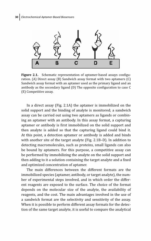
March 19, 2012 17:3 PSP Book - 9in x 6in 02-Ozsoz-c02
30 Electrochemical Aptamer-Based Biosensors
Figure 2.1. Schematic representation of aptamer-based assays configu-
ration. (A) Direct assay (B) Sandwich assay format with two aptamers (C)
Sandwich assay format with an aptamer used as the primary ligand and an
antibody as the secondary ligand (D) The opposite configuration to case C
(E) Competitive assay.
In a direct assay (Fig. 2.1A) the aptamer is immobilized on the
solid support and the binding of analyte is monitored; a sandwich
assay can be carried out using two aptamers as ligands or combin-
ing an aptamer with an antibody. In this assay format, a capturing
aptamer or antibody is first immobilized on the solid support and
then analyte is added so that the capturing ligand could bind it.
At this point, a detection aptamer or antibody is added and binds
with another site of the target analyte (Fig. 2.1B–D). In addition to
detecting macromolecules, such as proteins, small ligands can also
be bound by aptamers. For this purpose, a competitive assay can
be performed by immobilizing the analyte on the solid support and
then adding to it a solution containing the target analyte and a fixed
and optimized concentration of aptamer.
The main differences between the different formats are the
immobilized species (aptamer, antibody, or target analyte), the num-
ber of experimental steps involved, and in which order the differ-
ent reagents are exposed to the surface. The choice of the format
depends on the molecular size of the analyte, the availability of
reagents, and the cost. The main advantages involved in the use of
a sandwich format are the selectivity and sensitivity of the assay.
When it is possible to perform different assay formats for the detec-
tion of the same target analyte, it is useful to compare the analytical
March 19, 2012 17:3 PSP Book - 9in x 6in 02-Ozsoz-c02
Electrochemical Detection Strategies Based on Labeling 31
performances of each, in order to choose the approach that is the
best compromise in terms of sensitivity, specificity, analysis time,
and costs.
The high sensitivities requested by the aptamer-based assays for
the detection of the target analytes cannot be reached by a “direct
format,” since the affinities of aptamers for their targets are not high
enough, ranging from the micro to the nanomolar level. For this pur-
pose, several strategies have been used as signal amplification tools,
such as metallic and magnetic nanoparticles (NPs), enzymatic labels,
and quantum dots.
The potential use of aptamers as receptors in biosensors and
bioassays has been extensively reviewed [1–7] and also several
books have appeared in the last years [8, 9]. In this chapter, the cur-
rent status of research in electrochemical aptasensors is considered.
Attention is focused on label-free and labeled aptasensors, and the
analytical capabilities of these devices are discussed.
2.2 Electrochemical Detection StrategiesBased on Labeling
Labels such as enzymes, NPs, and redox species, such as fer-
rocene (Fc) or methylene blue (MB), are often used for recognition
processes. Electrochemical aptasensors with a label have received
and yet continue to receive considerable attention because they
combine the specificity of the aptamer–analyte recognition to the
advantages of an amplified signal. These strategies are generally
highly sensitive due to the analytical characteristics of the label used.
Labels are commonly covalently linked to terminal groups of
aptamers. The labeling position has to be carefully chosen so as not
to interfere with the folding of the aptamer and, thus, not to lose the
bioactivity or stability.
Among the most used labels are enzymes, such as peroxidise
(HRP), glucose oxidase (Gox), and alkaline phosphatase (AP), that
generate an electroactive product close to the transducer surface;
the formation of a relatively high local concentration of the enzyme
product leads to a significant signal amplification.
March 19, 2012 17:3 PSP Book - 9in x 6in 02-Ozsoz-c02
32 Electrochemical Aptamer-Based Biosensors
Electrochemical aptasensor based on the use of a label has found
various applications. In the following sections, some examples are
discussed.
2.3 Electrochemical Aptasensors Based ona Sandwich Assay
The use of a sandwich format allows detecting the target ana-
lyte with very high sensitivity and selectivity. Two conditions are
required: (1) the analyte possesses two epitopes which are so dif-
ferent that both ligands can bind to the analyte without the binding
of one affecting the binding of the other, and (2) two aptamers are
selected against such analyte. The disadvantage related to this for-
mat consists of several incubation steps that make the assay time
consuming.
This format is widely used in the case of large molecules such
as proteins and hormones; in particular it has been applied to
the detection of thrombin, which has been mostly used as model
system. Thrombin is an important serine protease in the blood
coagulation cascade. It contains a heparin-binding exosite and
fibrinogen-recognition exosite. In 1992, the first DNA thrombin
aptamer was isolated by Bock and coworkers [10] and the most
active strand was a 15-mer oligonucleotide with a K d around
100 nM. This aptamer interacts with the fibrinogen-recognition
exosite. The other thrombin-binding aptamer selected by Tasset and
coworkers [11] is a 29-mer single-stranded DNA with a K d around
0.5 nM. This aptamer binds to the heparin-binding exosite of throm-
bin. RNA aptamers for thrombin have also been selected.
Ikebukuro et al. [12] first reported an electrochemical aptasen-
sor for the detection of thrombin based on a sandwich-based assay.
Two different aptamers specific for thrombin were used: the 29-
mer thiolated aptamer and the 15-mer aptamer labeled with glu-
cose dehydrogenase (GDH). The thiolated aptamer was immobilized
onto gold electrodes; thrombin at different concentrations and then
the enzyme-labeled aptamer was added to the aptamer-modified
electrodes. The electric current generated by the addition of glu-
cose was measured at 0.1 V vs. Ag/AgCl in a buffer containing
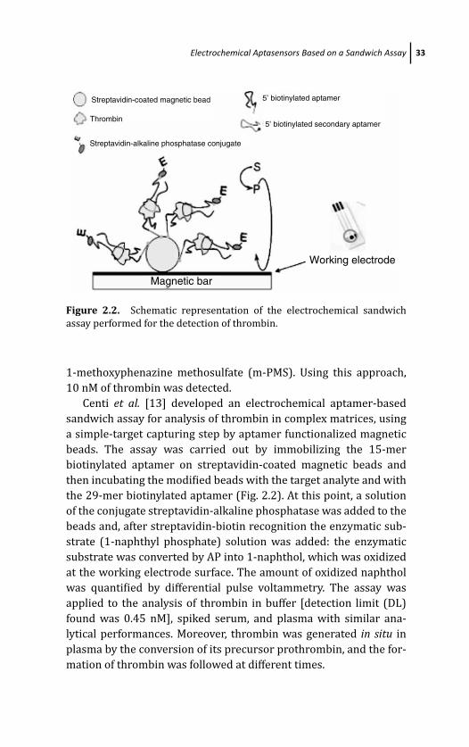
March 19, 2012 17:3 PSP Book - 9in x 6in 02-Ozsoz-c02
Electrochemical Aptasensors Based on a Sandwich Assay 33
Streptavidin-coated magnetic bead
Streptavidin-alkaline phosphatase conjugate
5’ biotinylated aptamer
5’ biotinylated secondary aptamerThrombin
Working electrode
Magnetic bar
Figure 2.2. Schematic representation of the electrochemical sandwich
assay performed for the detection of thrombin.
1-methoxyphenazine methosulfate (m-PMS). Using this approach,
10 nM of thrombin was detected.
Centi et al. [13] developed an electrochemical aptamer-based
sandwich assay for analysis of thrombin in complex matrices, using
a simple-target capturing step by aptamer functionalized magnetic
beads. The assay was carried out by immobilizing the 15-mer
biotinylated aptamer on streptavidin-coated magnetic beads and
then incubating the modified beads with the target analyte and with
the 29-mer biotinylated aptamer (Fig. 2.2). At this point, a solution
of the conjugate streptavidin-alkaline phosphatase was added to the
beads and, after streptavidin-biotin recognition the enzymatic sub-
strate (1-naphthyl phosphate) solution was added: the enzymatic
substrate was converted by AP into 1-naphthol, which was oxidized
at the working electrode surface. The amount of oxidized naphthol
was quantified by differential pulse voltammetry. The assay was
applied to the analysis of thrombin in buffer [detection limit (DL)
found was 0.45 nM], spiked serum, and plasma with similar ana-
lytical performances. Moreover, thrombin was generated in situ in
plasma by the conversion of its precursor prothrombin, and the for-
mation of thrombin was followed at different times.
March 19, 2012 17:3 PSP Book - 9in x 6in 02-Ozsoz-c02
34 Electrochemical Aptamer-Based Biosensors
An example of electrochemical sandwich assay for detection of
immunoglobulin E (IgE) is reported [14]. The assay was performed
by coupling an antibody against IgE with an aptamer anti-IgE.
Antibody molecules were covalently immobilized as capture probe
on gold electrodes via a self-assembled monolayer of cysteamine
through the glutaraldehyde-based bifunctional linking. After that the
target was captured, the biotinylated anti-IgE aptamer was added
because it could interact specifically with the analyte, followed by
the addition of a streptavidin-alkaline phosphatase (streptavidin-
AP) solution. Once biotin-streptavidin recognition occurred, the
signal amplification was achieved based on enzymatic silver depo-
sition. Ascorbic acid 2-phosphate was converted by AP into ascor-
bic acid, a strong reducing agent. It could reduce the silver ions in
the solution to silver metal that preferentially deposited on the gold
surface of electrodes. The amount of deposited silver, which is pro-
portional to the amount of IgE target bound on the electrode surface,
was quantified by linear sweep voltammetry.
The detection limit calculated using this approach was 0.02 nM of
thrombin. A similar approach was reported by Degefa and cowork-
ers [15] as well.
2.4 Electrochemical Aptasensors Based ona Competitive Assay
In literature no many examples of electrochemical enzyme-labeled
aptasensors based on a competitive assay are present. The advan-
tages of a competitive format (direct and indirect) are mainly related
to the fact that only one aptamer is required (considering that two
or more aptamers are not selected for many target analytes) and the
time necessary for the assay is faster.
A disposable electrochemical competitive assay for detection
of IgE was proposed by Papamichael et al. [16]. In this work the
IgE antigen was immobilized on the surface of screen-printed elec-
trodes, then a competition step between IgE bound to the electrode
surface and IgE in solution for the biotinylated aptamer was left to
occur. At this point the streptavidin-alkaline phosphatase conjugate
March 19, 2012 17:3 PSP Book - 9in x 6in 02-Ozsoz-c02
Electrochemical Aptasensors Based on a Competitive Assay 35
was added to the electrode. p-Aminophenyl phosphate (p-APP) was
used as enzymatic substrate and differential pulse voltammetry as
electrochemical technique. The results obtained with the electro-
chemical aptasensor were compared with those based on an ELISA-
type assay (ELONA). The aptasensor showed high specificity and
selectivity toward IgE with a detection limit of 23 ng/mL, which is
a concentration sufficient for detection of IgE in blood considering
that the IgE concentration in blood samples of healthy subjects is in
the range 240 to 290 ng/mL. Moreover, in this work the stability of
the assay performed using the aptamer against IgE was compared
with that of the assay carried out with a monoclonal antibody spe-
cific for IgE. Authors reported that the assay performed using the
aptamer was more stable than that with antibody, considering that
aptamers can be easily regenerated by also using harsh conditions
and are thermo-stable, because the aptamer folding is not affected
by the temperature.
Among the several strategies reported by Mir et al. [17] for the
detection of thrombin, an electrochemical aptasensor based on a
competitive assay resulted to be the most sensitive. Thrombin was
immobilized on gold-mercaptoethanol–treated electrodes by pas-
sive adsorption and then the modified electrodes were incubated
with a biotinylated aptamer anti-thrombin. The sensor was subse-
quently incubated with streptavidin-horseradish peroxidase conju-
gate, which bound to the biotin on the aptamer. The aptamer was
quantified by the electrochemical detection of the reaction catalyzed
by the peroxidase. Hydrogen peroxide was used as oxidizing agent
and [Os(bpy)2(pyr-CH2–NH2)]Cl as mediator. In this case the limit
of detection of thrombin was 3.5 nM. Thrombin was immobilized by
direct adsorption also on bare gold electrodes and on polystyrene
surfaces but it was not detectable on these unmodified surfaces.
It was supposed that in these surfaces the adsorption position of
thrombin created steric impediments preventing the subsequent
binding with the aptamer; alternatively, the binding of thrombin to
the surfaces may have denatured the protein.
Centi et al. [18] described various approaches for the devel-
opment of electrochemical aptasensors for the detection of
thrombin using magnetic beads as solid support and carbon
March 19, 2012 17:3 PSP Book - 9in x 6in 02-Ozsoz-c02
36 Electrochemical Aptamer-Based Biosensors
screen-printed electrodes as electrochemical transducers; among
the developed assay formats, a direct and an indirect competitive
assay was reported. The experimental work was also supported by
the use of the surface plasmon resonance (SPR) device Biacore XTM,
through which different information on the tested assay formats was
obtained. For the direct competitive assay the biotinylated 15-mer
aptamer was immobilized on streptavidin-coated magnetic beads,
whereas in the case of the indirect competitive assay, thrombin and
biotinylated thrombin was immobilized on the tosyl-activated and
streptavidin magnetic beads, respectively. Using a direct competitive
format, a detection limit of 430 nM of thrombin was achieved and a
good specificity of the assay was found using human serum albumin
as an interfering molecule.
Impedance spectroscopy, in this case faradic impedance spec-
troscopy (FIS), was used as transduction technique for a competi-
tive aptamer-based assay for the detection of neomycin B [19]. The
interesting feature of this work is the possibility of easily detecting a
small molecule like neomycin B with an electrochemical aptamer-
based assay. Actually, the detection of small molecules, such as
aminoglycoside antibiotics, is particularly challenging since only
time-consuming label-based immunoassays or HPLC methods have
been developed. On the contrary, in the present work an aptamer
specific for neomycin B [20] was used in a competitive/displacement
assay format. In particular, neomycin B was immobilized onto gold
electrodes and this modified surface was saturated with the specific
aptamer by affinity binding. By exposing the modified system to dif-
ferent concentrations of neomycin B, a displacement of the bound
aptamer was observed resulting in a drop of the electron-transfer
resistance consistent with the reduction of the negative charge of the
electrode surface. The competitive assay resulted very fast (equilib-
rium in 5 minutes) with a linear range covering two orders of mag-
nitude (0.75–500 μM) and a submicromolar limit of detection.
Very high specificity toward neomycin B was observed with
respect to other very similar antibiotics. Application of the method
to the analysis of real samples was also demonstrated by testing
neomycin spiked whole milk with a recovery of 102% and 109%,
respectively, for two different neomycin concentrations.
March 19, 2012 17:3 PSP Book - 9in x 6in 02-Ozsoz-c02
Electrochemical Aptasensors Based on a Direct Assay 37
2.5 Electrochemical Aptasensors Based on a Direct Assay
Some papers have used the catalytic activity of thrombin for the
determination of this protein. α-Human thrombin is a highly spe-
cific serine protease that catalyses the hydrolysis of the throm-
bin chromogenic substrate, β-Ala-Gly-Arg- p-nitroaniline producing
p-nitroaniline. The rate of yellow colored p-nitroaniline formation
can be followed by its UV absorption at 405 nm, or electrochemi-
cally by the reduction of its nitro group. The electrochemical detec-
tion offers benefits in terms of sensitivity and speed. When saturated
by enzyme substrate the formation rate of p-nitroaniline is propor-
tional to the enzyme concentration.
Mir et al. [17] first reported the detection of thrombin bound
to an aptamer selective for thrombin by the quantification of
p-nitroaniline produced by the enzymatic reaction catalyzed by
thrombin.
A mixed self-assembled monolayer was used for the aptamer
immobilization on the gold electrode. The aptamer-modified elec-
trodes were then incubated for 1 h at 37◦C with thrombin
(18 μg/mL). Electrochemical measurements were recorded in the
thin-layer cell configured to contain a total volume of 20 μL.
Thrombin chromogenic substrate (β-Ala-Gly-Arg- p-nitroaniline)
was injected into the cell and differential pulse voltammetry (DPV)
measurements between −0.2 and −1 V with a pulse height of −0.05
V and pulse duration of 70 ms were carried out. The DPV measure-
ments showed that β-Ala-Gly-Arg- p-nitroaniline substrate and the
p-nitroaniline product have different redox potentials. Moreover, the
DPV experiments showed a current peak at −0.45 V in the pres-
ence of the thrombin substrate. After 5 min, the peak at −0.45 V
decreased and a new peak was detected at −0.70 V, indicating the
formation of p-nitroaniline. The same measurements carried out on
a control electrode in order to test the specificity of the assay: in this
experiment bovine serum albumin (BSA) substituted thrombin and
in this case only the peak at 0.45 V was measured.
The authors demonstrated a huge reduction in the assay time
considering that the optical detection of p-nitroaniline needed 3 h
against 5 min necessary for the electrochemical measurement.
March 19, 2012 17:3 PSP Book - 9in x 6in 02-Ozsoz-c02
38 Electrochemical Aptamer-Based Biosensors
Centi et al. [18] compared the performances of several assay for-
mats based on the coupling of magnetic beads with electrochemi-
cal transduction always for the detection of thrombin. Among the
developed assays, one of the used strategies was based on the
direct measurement of the enzymatic product of thrombin captured
by the immobilized aptamer. The main differences between this
work and the work by Mir et al. [17] involve the use of magnetic
beads as solid support on which the aptamer-based assay is per-
formed. Streptavidin-coated magnetic beads modified by immobi-
lization of the biotinylated thrombin aptamer were incubated with
different concentrations of thrombin in the range 100 to 600 nM
for 30 min. Bound thrombin was detected by re-suspending the
beads in the thrombin substrate, β-Ala-Gly-Arg- p-nitroaniline, for
30 min at 37◦C. The solution containing the thrombin reaction prod-
uct was deposited onto the surface of the working screen-printed
graphite electrode, without any stirring. The aptamer-bound throm-
bin was detected by quantification of p-nitroaniline produced from
the thrombin catalyzed reaction. The DPV measurements showed a
decrease of the peak at −730 mV vs. Ag/AgCl pseudo-reference elec-
trode related to the β-Ala-Gly-Arg- p-nitroaniline substrate and the
appearance of a new peak at −870 mV vs. Ag/AgCl pseudo-reference
electrode, indicating the formation of p-nitroaniline (Fig. 2.3). The
same measurements were carried out in absence of thrombin, and
only a reproducible peak at −730 mV was observed (16.1±0.4 μA).
A linear increase of p-nitroaniline peak current was observed in the
studied concentration range of thrombin. On the contrary, a linear
decrease in thrombin substrate was observed increasing the throm-
bin concentration. The detection limit (DL) found for thrombin using
this approach was 175 nM.
In another direct approach, non-faradic electrochemical
impedance spectroscopy (NIS) was used for the direct detection of
platelet-derived growth factor-BB (PDGF-BB) [21]. Binding of PDGF
to its aptamer immobilized on a silicon electrode surface leads to
a decrease in capacitance measured by electrochemical impedance
spectroscopy (NIS). Because of the high sensitivity and specificity
(DL 40 nM) and the absence of reagent to be used when performing
the test, this biosensor design could be promising for in vivo moni-
toring.

March 19, 2012 17:3 PSP Book - 9in x 6in 02-Ozsoz-c02
Electrochemical Metal Nanoparticle-Labeled Aptasensors 39
Figure 2.3. DPV scans of the thrombin substrate (β-Ala-Gly-Arg- p-
nitroaniline) solutions incubated with aptamer-thrombin modified beads.
Different concentrations of thrombin in the concentration range 100 to
600 nM were incubated with the aptamer-modified beads, while a fixed con-
centration of thrombin substrate was used (200 μM). The thrombin sub-
strate and the p-nitroaniline released during hydrolysis showed different
redox potentials (the DPV peak potential of β-Ala-Gly-Arg- p-nitroaniline
was −730 mV vs. Ag/AgCl pseudo-reference electrode, whereas the
released p-nitroaniline peak potential was −870mV vs. Ag/AgCl pseudo-
reference electrode).
2.6 Electrochemical Metal Nanoparticle-LabeledAptasensors
The use of NP labels is a strategy relatively new in the develop-
ment of electrochemical aptasensors. The labels used are essentially
metallic NPs or inorganic (semiconductor) nanocrystals [22–25].
They allow developing elegant strategies for interfacing aptamer-
target analyte recognition events with electrochemical transduction
amplifying the resulting electrical response and thus giving rise to an
improvement of the assay sensitivity. In particular, the redox prop-
erties of gold NPs have made possible their widespread use as elec-
trochemical labels in aptasensor development [24]. Most of these
strategies involve a stripping measurement of the metal tag: metal
NPs can be oxidized to form the corresponding metal ions that can
be then detected electrochemically.
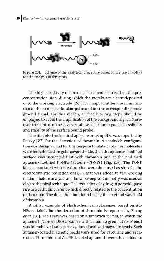
March 19, 2012 17:3 PSP Book - 9in x 6in 02-Ozsoz-c02
40 Electrochemical Aptamer-Based Biosensors
Figure 2.4. Scheme of the analytical procedure based on the use of Pt-NPs
for the analysis of thrombin.
The high sensitivity of such measurements is based on the pre-
concentration step, during which the metals are electrodeposited
onto the working electrode [26]. It is important for the minimiza-
tion of the non-specific adsorption and for the corresponding back-
ground signal. For this reason, surface blocking steps should be
employed to avoid the amplification of the background signal. More-
over, the control of the coverage allows to ensure a good accessibility
and stability of the surface bound probe.
The first electrochemical aptasensor using NPs was reported by
Polsky [27] for the detection of thrombin. A sandwich configura-
tion was designed and for this purpose thiolated aptamer molecules
were immobilized on gold-covered slide, then the aptamer-modified
surface was incubated first with thrombin and at the end with
aptamer-modified Pt-NPs (aptamer-Pt-NPs) (Fig. 2.4). The Pt-NP
labels associated with the thrombin were then used as sites for the
electrocatalytic reduction of H2O2 that was added to the working
medium before analysis and linear sweep voltammetry was used as
electrochemical technique. The reduction of hydrogen peroxide gave
rise to a cathodic current which directly related to the concentration
of thrombin. The detection limit found using this method was 1 nM
of thrombin.
Another example of electrochemical aptasensor based on Au-
NPs as labels for the detection of thrombin is reported by Zheng
et al. [28]. The assay was based on a sandwich format, in which the
aptamerI (15-mer DNA aptamer with an amino group at its 5’ end)
was immobilized onto carboxyl functionalized magnetic beads. Such
aptamer-coated magnetic beads were used for capturing and sepa-
ration. Thrombin and Au-NP–labeled aptamerII were then added to
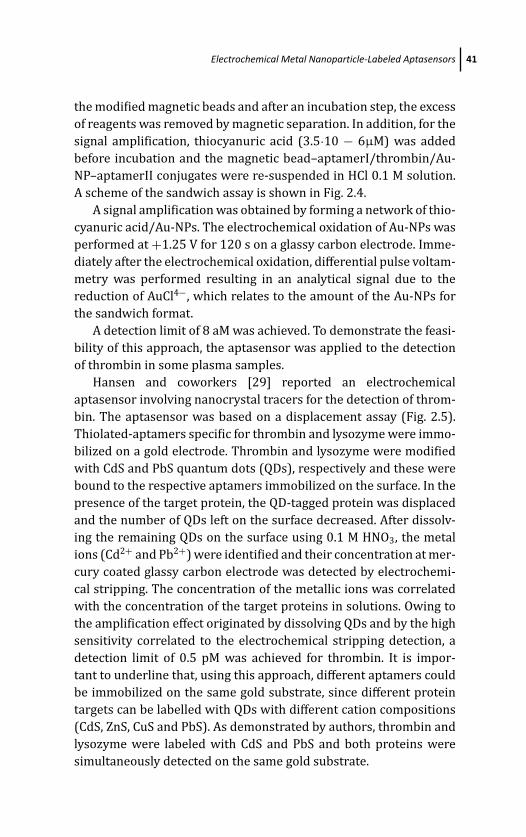
March 19, 2012 17:3 PSP Book - 9in x 6in 02-Ozsoz-c02
Electrochemical Metal Nanoparticle-Labeled Aptasensors 41
the modified magnetic beads and after an incubation step, the excess
of reagents was removed by magnetic separation. In addition, for the
signal amplification, thiocyanuric acid (3.5·10 − 6μM) was added
before incubation and the magnetic bead–aptamerI/thrombin/Au-
NP–aptamerII conjugates were re-suspended in HCl 0.1 M solution.
A scheme of the sandwich assay is shown in Fig. 2.4.
A signal amplification was obtained by forming a network of thio-
cyanuric acid/Au-NPs. The electrochemical oxidation of Au-NPs was
performed at +1.25 V for 120 s on a glassy carbon electrode. Imme-
diately after the electrochemical oxidation, differential pulse voltam-
metry was performed resulting in an analytical signal due to the
reduction of AuCl4−, which relates to the amount of the Au-NPs for
the sandwich format.
A detection limit of 8 aM was achieved. To demonstrate the feasi-
bility of this approach, the aptasensor was applied to the detection
of thrombin in some plasma samples.
Hansen and coworkers [29] reported an electrochemical
aptasensor involving nanocrystal tracers for the detection of throm-
bin. The aptasensor was based on a displacement assay (Fig. 2.5).
Thiolated-aptamers specific for thrombin and lysozyme were immo-
bilized on a gold electrode. Thrombin and lysozyme were modified
with CdS and PbS quantum dots (QDs), respectively and these were
bound to the respective aptamers immobilized on the surface. In the
presence of the target protein, the QD-tagged protein was displaced
and the number of QDs left on the surface decreased. After dissolv-
ing the remaining QDs on the surface using 0.1 M HNO3, the metal
ions (Cd2+ and Pb2+) were identified and their concentration at mer-
cury coated glassy carbon electrode was detected by electrochemi-
cal stripping. The concentration of the metallic ions was correlated
with the concentration of the target proteins in solutions. Owing to
the amplification effect originated by dissolving QDs and by the high
sensitivity correlated to the electrochemical stripping detection, a
detection limit of 0.5 pM was achieved for thrombin. It is impor-
tant to underline that, using this approach, different aptamers could
be immobilized on the same gold substrate, since different protein
targets can be labelled with QDs with different cation compositions
(CdS, ZnS, CuS and PbS). As demonstrated by authors, thrombin and
lysozyme were labeled with CdS and PbS and both proteins were
simultaneously detected on the same gold substrate.
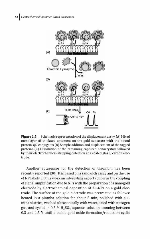
March 19, 2012 17:3 PSP Book - 9in x 6in 02-Ozsoz-c02
42 Electrochemical Aptamer-Based Biosensors
(C)
(B)
(A)
Thrombin Lysozyme
Wash
0.1M HNO3Cd Pb
Cd2+ & Pb2+
Figure 2.5. Schematic representation of the displacement assay. (A) Mixed
monolayer of thiolated aptamers on the gold substrate with the bound
protein-QD conjugates (B) Sample addition and displacement of the tagged
proteins (C) Dissolution of the remaining captured nanocrystals followed
by their electrochemical-stripping detection at a coated glassy carbon elec-
trode.
Another aptasensor for the detection of thrombin has been
recently reported [30]. It is based on a sandwich assay and on the use
of NP labels. In this work an interesting aspect concerns the coupling
of signal amplification due to NPs with the preparation of a nanogold
electrode by electrochemical deposition of Au-NPs on a gold elec-
trode. The surface of the gold electrode was pretreated as follows:
heated in a piranha solution for about 5 min, polished with alu-
mina slurries, washed ultrasonically with water, dried with nitrogen
gas, and cycled in 0.5 M H2SO4 aqueous solution scanning between
0.3 and 1.5 V until a stable gold oxide formation/reduction cyclic
March 19, 2012 17:3 PSP Book - 9in x 6in 02-Ozsoz-c02
Electrochemical Aptasensors Based on Noncovalent Redox Species Label 43
voltammogram was obtained. The electrochemical deposition of Au-
NP was carried out in the HAuCl4 solution containing 0.1 M KNO3
as electrolyte at −400 mV. The freshly prepared nanogold electrode
was incubated with the thiolated 15-mer aptamer anti-thrombin for
about 16 h to produce an aptamer attached electrode. Then the
modified electrode was immersed in a solution of 6-mercapto-1-
hexanol for 1 h to block the uncovered gold surface. At this point,
the aptamer-modified electrode was interacted with different con-
centrations of thrombin and then with a solution of Au-NP probe.
It consisted of Au-NPs conjugated to the thiolated 15-mer aptamer
anti-thrombin and to CdS-NPs linked with a single-stranded DNA
sequence. The resulting sandwich complex was treated with 1.0 M
of HNO3 solution for 5 min to dissolve the CdS-NPs and then with
acetate buffer containing Hg2+. The DPV measurements of the dis-
solved Cd2+ were performed using an in situ prepared mercury film
on a glassy carbon electrode with a deposition time of 300 s and
deposition potential of −1.1 V. An anodic stripping peak current at
−0.67 V was taken as the analytical response.
A detection limit of 0.55 fM of thrombin was calculated. Authors
attribute the significant improvement of the sensitivity of such
aptasensors with respect to others present in literature to the use
of a nanoelectrode, formed by immobilization of Au-NPs on the sur-
face of a gold electrode, to the use of NPs as labels, and to the use of
DPV technique for the detection of the dissolved Cd2+ in the solution.
Moreover, the electrochemical aptasensor was successfully tested in
some serum samples.
2.7 Electrochemical Aptasensors Based on NoncovalentRedox Species Label
These aptasensors are based on the use of a redox probe such
as methylene blue (MB) that undergoes an oxidation and reduc-
tion due to the electron transfer from an electrode surface to a
probe. These redox probes are noncovalently bound to aptamers and
intercalate or interact with aptamers mainly by electrostatic inter-
actions. For example, MB, positively charged, interacts with nega-
tively charged proteins or other negatively charged analytes. When
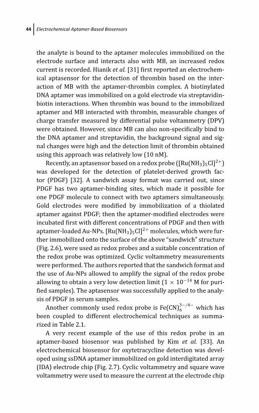
March 19, 2012 17:3 PSP Book - 9in x 6in 02-Ozsoz-c02
44 Electrochemical Aptamer-Based Biosensors
the analyte is bound to the aptamer molecules immobilized on the
electrode surface and interacts also with MB, an increased redox
current is recorded. Hianik et al. [31] first reported an electrochem-
ical aptasensor for the detection of thrombin based on the inter-
action of MB with the aptamer-thrombin complex. A biotinylated
DNA aptamer was immobilized on a gold electrode via streptavidin-
biotin interactions. When thrombin was bound to the immobilized
aptamer and MB interacted with thrombin, measurable changes of
charge transfer measured by differential pulse voltammetry (DPV)
were obtained. However, since MB can also non-specifically bind to
the DNA aptamer and streptavidin, the background signal and sig-
nal changes were high and the detection limit of thrombin obtained
using this approach was relatively low (10 nM).
Recently, an aptasensor based on a redox probe ([Ru(NH3)5Cl]2+)
was developed for the detection of platelet-derived growth fac-
tor (PDGF) [32]. A sandwich assay format was carried out, since
PDGF has two aptamer-binding sites, which made it possible for
one PDGF molecule to connect with two aptamers simultaneously.
Gold electrodes were modified by immobilization of a thiolated
aptamer against PDGF; then the aptamer-modified electrodes were
incubated first with different concentrations of PDGF and then with
aptamer-loaded Au-NPs. [Ru(NH3)5Cl]2+ molecules, which were fur-
ther immobilized onto the surface of the above “sandwich” structure
(Fig. 2.6), were used as redox probes and a suitable concentration of
the redox probe was optimized. Cyclic voltammetry measurements
were performed. The authors reported that the sandwich format and
the use of Au-NPs allowed to amplify the signal of the redox probe
allowing to obtain a very low detection limit (1 × 10⁻¹⁴ M for puri-
fied samples). The aptasensor was successfully applied to the analy-
sis of PDGF in serum samples.
Another commonly used redox probe is Fe(CN)3−/4−6 which has
been coupled to different electrochemical techniques as summa-
rized in Table 2.1.
A very recent example of the use of this redox probe in an
aptamer-based biosensor was published by Kim et al. [33]. An
electrochemical biosensor for oxytetracycline detection was devel-
oped using ssDNA aptamer immobilized on gold interdigitated array
(IDA) electrode chip (Fig. 2.7). Cyclic voltammetry and square wave
voltammetry were used to measure the current at the electrode chip
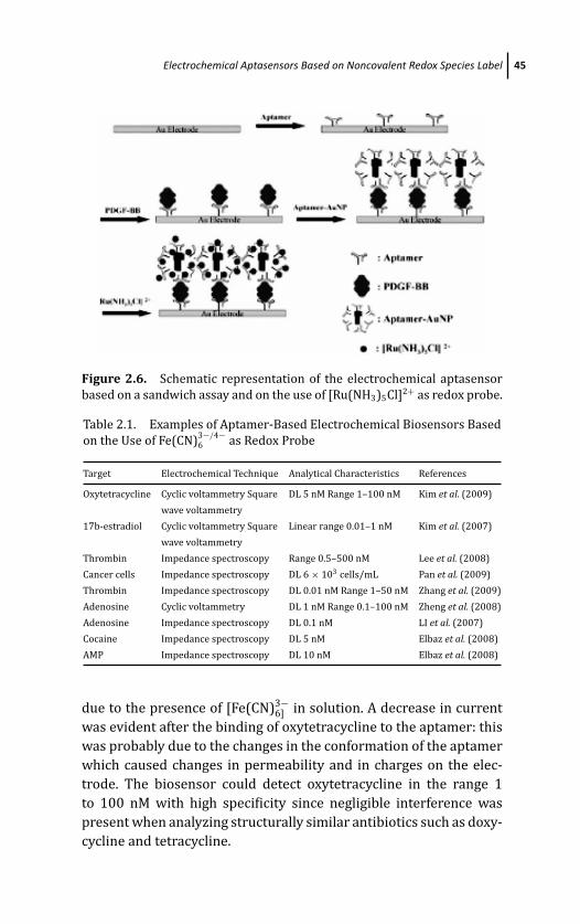
March 19, 2012 17:3 PSP Book - 9in x 6in 02-Ozsoz-c02
Electrochemical Aptasensors Based on Noncovalent Redox Species Label 45
Figure 2.6. Schematic representation of the electrochemical aptasensor
based on a sandwich assay and on the use of [Ru(NH3)5Cl]2+ as redox probe.
Table 2.1. Examples of Aptamer-Based Electrochemical Biosensors Based
on the Use of Fe(CN)3−/4−6 as Redox Probe
Target Electrochemical Technique Analytical Characteristics References
Oxytetracycline Cyclic voltammetry Square DL 5 nM Range 1–100 nM Kim et al. (2009)
wave voltammetry
17b-estradiol Cyclic voltammetry Square Linear range 0.01–1 nM Kim et al. (2007)
wave voltammetry
Thrombin Impedance spectroscopy Range 0.5–500 nM Lee et al. (2008)
Cancer cells Impedance spectroscopy DL 6 × 10³ cells/mL Pan et al. (2009)
Thrombin Impedance spectroscopy DL 0.01 nM Range 1–50 nM Zhang et al. (2009)
Adenosine Cyclic voltammetry DL 1 nM Range 0.1–100 nM Zheng et al. (2008)
Adenosine Impedance spectroscopy DL 0.1 nM LI et al. (2007)
Cocaine Impedance spectroscopy DL 5 nM Elbaz et al. (2008)
AMP Impedance spectroscopy DL 10 nM Elbaz et al. (2008)
due to the presence of [Fe(CN)3−6] in solution. A decrease in current
was evident after the binding of oxytetracycline to the aptamer: this
was probably due to the changes in the conformation of the aptamer
which caused changes in permeability and in charges on the elec-
trode. The biosensor could detect oxytetracycline in the range 1
to 100 nM with high specificity since negligible interference was
present when analyzing structurally similar antibiotics such as doxy-
cycline and tetracycline.
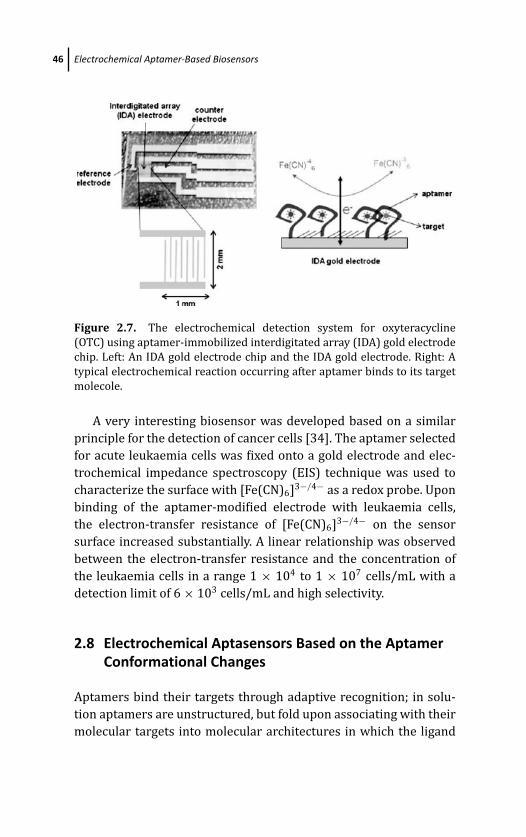
March 19, 2012 17:3 PSP Book - 9in x 6in 02-Ozsoz-c02
46 Electrochemical Aptamer-Based Biosensors
Figure 2.7. The electrochemical detection system for oxyteracycline
(OTC) using aptamer-immobilized interdigitated array (IDA) gold electrode
chip. Left: An IDA gold electrode chip and the IDA gold electrode. Right: A
typical electrochemical reaction occurring after aptamer binds to its target
molecole.
A very interesting biosensor was developed based on a similar
principle for the detection of cancer cells [34]. The aptamer selected
for acute leukaemia cells was fixed onto a gold electrode and elec-
trochemical impedance spectroscopy (EIS) technique was used to
characterize the surface with [Fe(CN)6]3−/4− as a redox probe. Upon
binding of the aptamer-modified electrode with leukaemia cells,
the electron-transfer resistance of [Fe(CN)6]3−/4− on the sensor
surface increased substantially. A linear relationship was observed
between the electron-transfer resistance and the concentration of
the leukaemia cells in a range 1 × 10⁴ to 1 × 10⁷ cells/mL with a
detection limit of 6 × 10³ cells/mL and high selectivity.
2.8 Electrochemical Aptasensors Based on the AptamerConformational Changes
Aptamers bind their targets through adaptive recognition; in solu-
tion aptamers are unstructured, but fold upon associating with their
molecular targets into molecular architectures in which the ligand
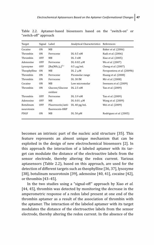
March 19, 2012 17:3 PSP Book - 9in x 6in 02-Ozsoz-c02
Electrochemical Aptasensors Based on the Aptamer Conformational Changes 47
Table 2.2. Aptamer-based biosensors based on the “switch-on” or
“switch-off” approach
Target Signal Label Analytical Characteristics References
Cocaine ON MB Baker et al. (2006)
Thrombin ON Ferrocene DL 0.5 nM Radi et al. (2006)
Thrombin OFF MB DL 3 nM Xiao et al. (2005)
Adenosine OFF Ferrocene DL 0.02 μM Wu et al. (2007)
Lysozyme OFF [Ru(NH3)6]3+ 0.5 μg/mL Cheng et al. (2007)
Theophylline ON MB DL 2 μM Feropontova et al. (2009b)
Thrombin ON Ferrocene Picomolar range Huang et al. (2008)
Thrombin ON Ferrocene DL 30 fM Mir et al. (2008)
Cocaine ON MB Low micromolar Swensen et al. (2009)
Thrombin ON Glucose/Glucose DL 2.5 nM Tan et al. (2009)
oxidase
Thrombin OFF Ferrocene DL 3.9 nM Tan et al. (2009)
Adenosine OFF MB DL 0.01 μM Wang et al. (2009)
Botulinum OFF Fluorescein/anti- DL 40 pg/mL Wei et al. (2009)
neurotoxin fluorescein-HRP
PDGF ON MB DL 50 pM Rodriguez et al. (2005)
becomes an intrinsic part of the nucleic acid structure [35]. This
feature represents an almost unique mechanism that can be
exploited in the design of new electrochemical biosensors [2]. In
this approach the interaction of a labeled aptamer with its tar-
get can modulate the distance of the electroactive labels from the
sensor electrode, thereby altering the redox current. Various
aptasensors (Table 2.2), based on this approach, are used for the
detection of different targets such as theophylline [36, 37], lysozyme
[38], botulinum neuorotoxin [39], adenosine [40, 41], cocaine [42],
or thrombin [43–45].
In the two studies using a “signal-off” approach by Xiao et al.[44, 45], thrombin was detected by monitoring the decrease in the
amperometric response of a redox label present at one end of the
thrombin aptamer as a result of the association of thrombin with
the aptamer. The interaction of the labeled aptamer with its target
modulates the distance of the electroactive labels from the sensor
electrode, thereby altering the redox current. In the absence of the
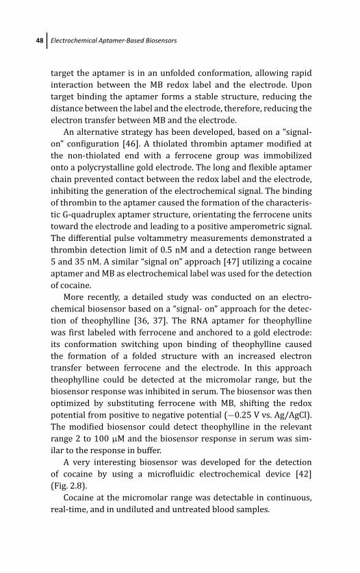
March 19, 2012 17:3 PSP Book - 9in x 6in 02-Ozsoz-c02
48 Electrochemical Aptamer-Based Biosensors
target the aptamer is in an unfolded conformation, allowing rapid
interaction between the MB redox label and the electrode. Upon
target binding the aptamer forms a stable structure, reducing the
distance between the label and the electrode, therefore, reducing the
electron transfer between MB and the electrode.
An alternative strategy has been developed, based on a “signal-
on” configuration [46]. A thiolated thrombin aptamer modified at
the non-thiolated end with a ferrocene group was immobilized
onto a polycrystalline gold electrode. The long and flexible aptamer
chain prevented contact between the redox label and the electrode,
inhibiting the generation of the electrochemical signal. The binding
of thrombin to the aptamer caused the formation of the characteris-
tic G-quadruplex aptamer structure, orientating the ferrocene units
toward the electrode and leading to a positive amperometric signal.
The differential pulse voltammetry measurements demonstrated a
thrombin detection limit of 0.5 nM and a detection range between
5 and 35 nM. A similar “signal on” approach [47] utilizing a cocaine
aptamer and MB as electrochemical label was used for the detection
of cocaine.
More recently, a detailed study was conducted on an electro-
chemical biosensor based on a “signal- on” approach for the detec-
tion of theophylline [36, 37]. The RNA aptamer for theophylline
was first labeled with ferrocene and anchored to a gold electrode:
its conformation switching upon binding of theophylline caused
the formation of a folded structure with an increased electron
transfer between ferrocene and the electrode. In this approach
theophylline could be detected at the micromolar range, but the
biosensor response was inhibited in serum. The biosensor was then
optimized by substituting ferrocene with MB, shifting the redox
potential from positive to negative potential (−0.25 V vs. Ag/AgCl).
The modified biosensor could detect theophylline in the relevant
range 2 to 100 μM and the biosensor response in serum was sim-
ilar to the response in buffer.
A very interesting biosensor was developed for the detection
of cocaine by using a microfluidic electrochemical device [42]
(Fig. 2.8).
Cocaine at the micromolar range was detectable in continuous,
real-time, and in undiluted and untreated blood samples.
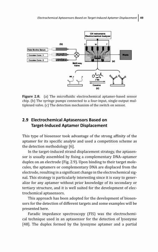
March 19, 2012 17:3 PSP Book - 9in x 6in 02-Ozsoz-c02
Electrochemical Aptasensors Based on Target-Induced Aptamer Displacement 49
Figure 2.8. (a) The microfluidic electrochemical aptamer-based sensor
chip. (b) The syringe pumps connected to a four-input, single-output mul-
tiplexed valve. (c) The detection mechanism of the switch on sensor.
2.9 Electrochemical Aptasensors Based onTarget-Induced Aptamer Displacement
This type of biosensor took advantage of the strong affinity of the
aptamer for its specific analyte and used a competition scheme as
the detection methodology [6].
In the target-induced strand displacement strategy, the aptasen-
sor is usually assembled by fixing a complementary DNA–aptamer
duplex on an electrode (Fig. 2.9). Upon binding to their target mole-
cules, the aptamers or complementary DNA are displaced from the
electrode, resulting in a significant change in the electrochemical sig-
nal. This strategy is particularly interesting since it is easy to gener-
alize for any aptamer without prior knowledge of its secondary or
tertiary structure, and it is well suited for the development of elec-
trochemical aptasensors.
This approach has been adopted for the development of biosen-
sors for the detection of different targets and some examples will be
presented here.
Faradic impedance spectroscopy (FIS) was the electrochemi-
cal technique used in an aptasensor for the detection of lysozyme
[48]. The duplex formed by the lysozyme aptamer and a partial
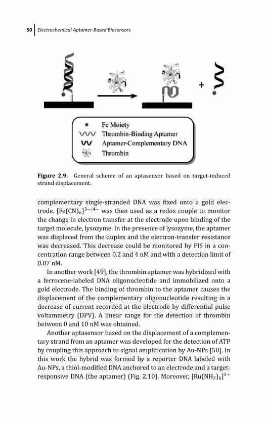
March 19, 2012 17:3 PSP Book - 9in x 6in 02-Ozsoz-c02
50 Electrochemical Aptamer-Based Biosensors
Figure 2.9. General scheme of an aptasensor based on target-induced
strand displacement.
complementary single-stranded DNA was fixed onto a gold elec-
trode. [Fe(CN)6]3−/4− was then used as a redox couple to monitor
the change in electron transfer at the electrode upon binding of the
target molecule, lysozyme. In the presence of lysozyme, the aptamer
was displaced from the duplex and the electron-transfer resistance
was decreased. This decrease could be monitored by FIS in a con-
centration range between 0.2 and 4 nM and with a detection limit of
0.07 nM.
In another work [49], the thrombin aptamer was hybridized with
a ferrocene-labeled DNA oligonucleotide and immobilized onto a
gold electrode. The binding of thrombin to the aptamer causes the
displacement of the complementary oligonucleotide resulting in a
decrease of current recorded at the electrode by differential pulse
voltammetry (DPV). A linear range for the detection of thrombin
between 0 and 10 nM was obtained.
Another aptasensor based on the displacement of a complemen-
tary strand from an aptamer was developed for the detection of ATP
by coupling this approach to signal amplification by Au-NPs [50]. In
this work the hybrid was formed by a reporter DNA labeled with
Au-NPs, a thiol-modified DNA anchored to an electrode and a target-
responsive DNA (the aptamer) (Fig. 2.10). Moreover, [Ru(NH3)6]3+
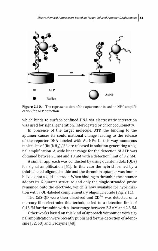
March 19, 2012 17:3 PSP Book - 9in x 6in 02-Ozsoz-c02
Electrochemical Aptasensors Based on Target-Induced Aptamer Displacement 51
Figure 2.10. The representation of the aptasensor based on NPs’ amplifi-
cation for ATP detection.
which binds to surface-confined DNA via electrostatic interaction
was used for signal generation, interrogated by chronocoulometry.
In presence of the target molecule, ATP, the binding to the
aptamer causes its conformational change leading to the release
of the reporter DNA labeled with Au-NPs. In this way numerous
molecules of [Ru(NH3)6]3+ are released in solution generating a sig-
nal amplification. A wide linear range for the detection of ATP was
obtained between 1 nM and 10 μM with a detection limit of 0.2 nM.
A similar approach was conducted by using quantum dots (QDs)
for signal amplification [51]. In this case the hybrid formed by a
thiol-labeled oligonucleotide and the thrombin aptamer was immo-
bilized onto a gold electrode. When binding to thrombin the aptamer
adopts its G-quartet structure and only the single-stranded probe
remained onto the electrode, which is now available for hybridiza-
tion with a QD-labeled complementary oligonucleotide (Fig. 2.11).
The CdS-QD were then dissolved and CD2+ was detected on a
mercury-film electrode: this technique led to a detection limit of
0.43 fM for thrombin with a linear range between 2.3 nM and 2.3 fM.
Other works based on this kind of approach without or with sig-
nal amplification were recently published for the detection of adeno-
sine [52, 53] and lysozyme [48].
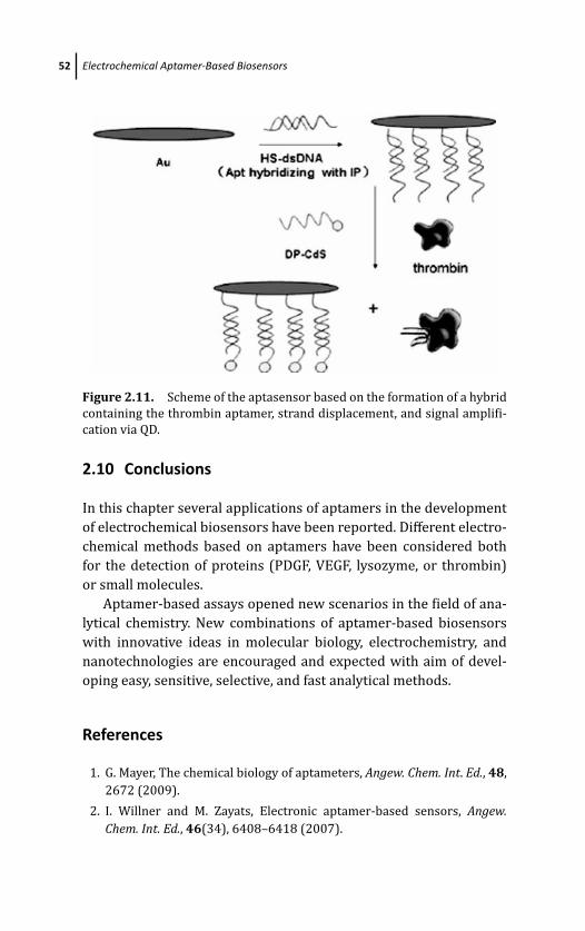
March 19, 2012 17:3 PSP Book - 9in x 6in 02-Ozsoz-c02
52 Electrochemical Aptamer-Based Biosensors
Figure 2.11. Scheme of the aptasensor based on the formation of a hybrid
containing the thrombin aptamer, strand displacement, and signal amplifi-
cation via QD.
2.10 Conclusions
In this chapter several applications of aptamers in the development
of electrochemical biosensors have been reported. Different electro-
chemical methods based on aptamers have been considered both
for the detection of proteins (PDGF, VEGF, lysozyme, or thrombin)
or small molecules.
Aptamer-based assays opened new scenarios in the field of ana-
lytical chemistry. New combinations of aptamer-based biosensors
with innovative ideas in molecular biology, electrochemistry, and
nanotechnologies are encouraged and expected with aim of devel-
oping easy, sensitive, selective, and fast analytical methods.
References
1. G. Mayer, The chemical biology of aptameters, Angew. Chem. Int. Ed., 48,
2672 (2009).
2. I. Willner and M. Zayats, Electronic aptamer-based sensors, Angew.Chem. Int. Ed., 46(34), 6408–6418 (2007).
March 19, 2012 17:3 PSP Book - 9in x 6in 02-Ozsoz-c02
References 53
3. S. Song, L. Wang, J. Li, J. Zhao, and C. Fan, Aptameter-based biosensors,
Trends Anal. Chem., 27, 108 (2008).
4. T. Nguyen, J. P. Hilton, and Q. Lin, Emerging applications of aptamers
to micro- and nanoscale biosensing, Microfluid. Nanofluid., 6, 347–362
(2009).
5. K. Sefah, J. A. Phillips, X. Xiong, L. Meng, D. Van Simaeys, H. Chen, and W.
Tan, Analyst, 134, 1765, (2009).
6. A. K. H. Cheng, D. Sen, and H. Z. Yu, Design and testing of aptamer-based
electrochemical biosensors for proteins and small molecules, Bioelec-trochemistry, 77, 1–12 (2009).
7. S. Tombelli and M. Mascini, Curr. Opin. Mol. Ther., 11, 179 (2009).
8. S. Klussmann (ed.), The Aptamer Handbook, Wiley-VCH Verlag GmbH &
Co. KGaA, Weinheim, (2006).
9. M. Mascini, (ed.), Aptamers in Bioanalysis, John Wiley & Sons, Inc., Hobo-
ken, New Jersey, (2008).
10. L. C. Bock, L. C. Griffin, J. A. Latham, E. H. Vermaas, and J. J. Toole, Selec-
tion of single-stranded DNA molecules that bind and inhibit human
thrombin, Nature, 355, 564–566 (1992).
11. D. M. Tasset, M. F. Kubik, and W. Steiner, Oligonucleotide inhibitors of
human thrombin that bind distinct epitopes, J. Mol. Biol., 272, 688–698
(2007).
12. K. Ikebukuro, C. Kiyohara, and K. Sode, Electrochemical detection of
protein using a double aptamer sandwich, Anal. Lett., 37, 2901–2909
(2004).
13. S. Centi, S. Tombelli, M. Minunni, and M. Mascini, Aptamer-based detec-
tion of plasma proteins by an electrochemical assay coupled to magnetic
beads, Anal. Chem., 79, 1466–1473 (2007).
14. K. Feng, C. Sun, Y. Kang, J. Chen, J.-H. Jiang, G.-L. Shen, and R.-Q. Yu, Label-
free electrochemical detection of nanomolar adenosine based on target-
induced aptamer displacement, Electr. Comm., 10, 531–535 (2008).
15. T. H. Degefa, S. Hwang, D. Kwon, J. H. Park, and J. Kwak, Aptamer-based
electrochemical detection of protein using enzymatic silver deposition,
Electrochim. Acta, 54, 6788–6791 (2009).
16. K. I. Papamichael, M. P. Kreuzer, and G. G. Guilbault, Viability of allergy
(IgE) detection using an alternative aptamer receptor and electrochem-
ical means, Sens. Actuators B, 121, 178–186 (2007).
17. M. Mir, M. Vreeke, and I. Katakis, Different strategies to develop an elec-
trochemical thrombin aptasensor, Electrochem. Commun., 8, 505–511
(2006).
March 19, 2012 17:3 PSP Book - 9in x 6in 02-Ozsoz-c02
54 Electrochemical Aptamer-Based Biosensors
18. S. Centi, G. Messina, S. Tombelli, I. Palchetti, and M. Mascini, Differ-
ent approaches for the detection of thrombin by an electrochemical
aptamer-based assay coupled to magnetic beads, Biosens. Bioelectron.,23, 1602–1609 (2008).
19. N. De-los-Santos-Alvarez, M. J. Lobo-Castanon, A. J. Miranda-Ordieres,
and P. J. Tunon-Blanco, J. Am. Chem. Soc., 129, 3808, 2007.
20. J. A. Cowan, T. Ohyama, D. Q. Wang, and K. Natarajan, Nucleic Acids Res.,
28, 2935 (2000).
21. W. Liao and X. T. Cui, Reagentless aptamer based impedance biosensor
for monitorino a neuro-inflammatory cytokine PDGF, Biosens. Bioelec-tron., 23, 218–224 (2007).
22. S. Guo and E. Wang, Synthesis and electrochemical applications of gold
nanoparticles, Anal. Chim. Acta, 598, 181–192 (2007).
23. A. Escosura-Muniz, A. Ambrosi, and A. Merkoci, Electrochemical analy-
sis with nanoparticle-based biosystems, Trends Anal. Chem., 27(7), 568–
584 (2008).
24. Z. Wang and L. Ma, Gold nanoparticle probes, Coord. Chem. Rev., 253,
1607–1618 (2009).
25. R. Wilson, The use of gold nanoparticles in diagnostics and detection,
Chem. Soc. Rev., 37, 2028–2045 (2008).
26. J. Wang, Nanoparticle-based electrochemical bioassays of proteins, Elec-troanalysis, 19(7–8), 769–776 (2007).
27. R. Polsky, R. Gill, L. Kaganovsky, and I. Willner, Nucleic acid functional-
ized Pt nanoparticles: catalytic labels for the amplified electrochemical
detection of biomolecules, Anal. Chem., 78, 2268–2271 (2006).
28. J. Zheng, W. Feng, L. Lin, F. Zhang, G. Cheng, P. He, and Y. Fang, A
new amplification strategy for ultrasensitive electrochemical aptasen-
sor with network-like thiocyanuric acid/gold nanoparticles, Biosens.Bioelectron., 23, 341–347 (2007).
29. J. A. Hansen, J. Wang, A.-N. Kawde, Y. Xiang, K. V. Gothelf, and G.
Collins Quantum-dot/Aptamer-based ultrasensitive multi-analyte elec-
trochemical biosensor, J. Am. Chem. Soc., 128, 2228–2229 (2006).
30. C. Ding, Y. Ge, and J.-M. Lin, Aptamer based electrochemical assay for the
determination of thrombin by using the amplification of the nanoparti-
cles, Biosens. Bioelectron, doi:10.1016/j.bios.2009.10.017 (2009).
31. T. Hianik, V. Ostatna, Z. Zajacova, E. Stoikova, and G. Evtugyn, Detection of
aptamer–protein interactions using QCM and electrochemical indicator
methods, Bioorg. Med. Chem. Lett., 15, 291–295 (2005).
March 19, 2012 17:3 PSP Book - 9in x 6in 02-Ozsoz-c02
References 55
32. J. Wang, W. Meng, X. Zheng, S. Liu, and G. Li, Combination of aptamer
with gold nanoparticles for electrochemical signal amplification: appli-
cation to sensitive detection of platelet-derived growth factor, Biosens.Bioelectron., 24, 1598–1602 (2009).
33. Y. S. Kim, J. H. Niazi, and M. B. Gu, Specific detection of oxytetracycline
using DNA aptamer-immobilized interdigitated array electrode chip,
Anal. Chim. Acta, 634, 250–254 (2009).
34. C. Pan, M. Guo, Z. Nie, X. Xiao, and S. Yao, Aptamer-based electrochemical
sensor for label-free recognition and detection of cancer cells, Electro-analysis, 21, 321–1326 (2009).
35. T. Hermann and D. J. Patel, Adaptive recognition by nucleic acid
aptamers, Science, 287, (5454), 820–825 (2000).
36. E. E. Ferapontova and K. V. Gothelf, Optimization of the electrochemi-
cal RNA-aptamer based biosensor fo theophylline by using a methylene
blue redox label, Electroanalysis, 21, 261–1266 (2009a).
37. E. E. Ferapontova and K. V. Gothelf, Effect of serum on an RNA aptamer-
based electrochemical sensor for theophylline, Langmuir, 25, 4279–
4283 (2009b).
38. A. K. Cheng, B. Ge, and H. Z. Yu,Aptamer-based biosensors for label-free
voltammetric detection of lysozyme, Anal. Chem., 79(14), 5158–5164
(2007).
39. F. Wei and C. M. Ho, Aptamer-based electrochemical biosensor for
Botulinum neurotoxin, Anal. Bioanal. Chem., 393, 1943–1948 (2009).
40. J. Wang, F. Wang, and S. Dong, Methylene blue as an indicator for sen-
sitive electrochemical detection of adenosine based on aptamer switch,
J. Electroanal. Chem., 626, 1–5 (2009).
41. Z. S. Wu, M. M. Guo, S. B. Zhang, C. R. Chen, J. H. Jiang, G. L. Shen, and
R. Q. Yu, Reusable electrochemical sensing platform for highly sensitive
detection of small molecules based on structure-switching signalling
aptamers, Anal. Chem., 79(7), 2933–2939 (2007).
42. J. S. Swensen, Y. Xiao, B. S. Ferguson, A. A. Lubin, R. Y., Lai, A. J.
Heeger, K. W. Plaxco, and H. T. Soh, Continuous, real-time monitor-
ing of cocaine in undiluted blood serum via a mocrifluidic, electro-
chemical aptamer-based sensor, J. Am. Chem. Soc., 131, 4262–4266
(2009).
43. E. S. Q. Tan, R. Wivanius, and C. S. Toh, Heterogeneous and homogeneous
aptamer-based electrochemical sensors for thrombin, Electroanalysis,
21, 749–754 (2009).
March 19, 2012 17:3 PSP Book - 9in x 6in 02-Ozsoz-c02
56 Electrochemical Aptamer-Based Biosensors
44. Y. Xiao, A. A. Lubin, A. J. Heeger, and K. W. Plaxco, Label-free electronic
detection of thrombin in blood serum by using an aptamer-based sen-
sor, Angew. Chem. Int. Ed., 44(34), 5456–5459 (2005a).
45. Y. Xiao, D. Piorek, K. W. Plaxco, and A. J. Heeger, A reagentless signal-on
architecture for electronic, aptamer-based sensors via target-induced
strand displacement, J. Am. Chem. Soc., 127(51), 17990–17991 (2005b).
46. A. E. Radi, J. L. Acero Sanchez, E. Baldrich, and C. K. O’Sullivan, Reagent-
less, reusable, ultrasensitive electrochemical molecular beacon aptasen-
sor, J. Am. Chem. Soc., 128(1), 117–124 (2006).
47. B. R. Baker, R. Y. Lai, M. S. Wood, E. H. Doctor, A. J. Heeger, and K.
W. Plaxco, An electronic aptamer-based small-molecule sensor for the
rapid label-free detection of cocaine in adulterated samples and biolog-
ical fluids, J. Am. Chem. Soc., 128(10), 3138–3139 (2006).
48. Y. Peng, D. Zhang, Y. Li, H. Qi, Q. Gao, and C. Zhang, Label-free and sen-
sitive faradic impedance aptasensor for the determination of lysozyme
based on target-induced aptamer displacement, Biosens. Bioelectron.,25, 94–99 (2009).
49. Y. Lu, N. Zhu, P. Yu, P., and L. Mao, Aptamer-based electrochemical sen-
sors that are not based on the target binding-induced conformational
change of aptamers, Analyst, 133(9), 1256–1260 (2008).
50. B. L. Li, Y. Du, H. Wei, and S. J. Dong, Reusable, label-free electrochemical
aptasensor for sensitive detection of small molecules, Chem. Commun.,
3780–3782 (2007).
51. X. Zuo, S. Song, J. Zhang, D. Pan, L. Wang, and C. Fan, A target-responsive
electrochemical aptamer switch (TREAS) for reagentless detection of
nanomolar ATP, J. Am. Chem. Soc., 129, 1042–1043 (2007).
52. S. Zhang, J. Xia, and X. Li, Electrochemical biosensor for detection
of adenosine based on structure-switching aptamer and amplification
with reporter probe DNA modified Au nanoparticles, Anal. Chem., 80,
8382–8388 (2008).
March 19, 2012 17:4 PSP Book - 9in x 6in 03-Ozsoz-c03
Chapter 3
Carbon-Polymer Bio-Nano-CompositeElectrodes for ElectrochemicalGenosensing
Marıa Isabel Pividori and Salvador AlegretGrup de Sensors i Biosensors, Departament de Quımica,Universitat Autonoma de Barcelona, Barcelona, [email protected]
This chapter reports the main features of rigid carbon–polymer
composite materials for electrochemical DNA biosensing. Novel
approaches based on composites modified with biomolecules (bio-
composites) and nanostructured materials (nanocomposites) for
the improved biosensing of DNA are also discussed.
3.1 Introduction
The use of nucleic acids as biorecognition elements represents an
exciting interdisciplinary area of research in converging technolo-
gies. The oriented and improved immobilization of single-stranded
DNA to solid substrates, followed by hybridization and detection
of this event, has gained importance over the past decade, due
to the growing demand for genetic information in an increasingly
Electrochemical DNA BiosensorsEdited by Mehmet OzsozCopyright c© 2012 Pan Stanford Publishing Pte. Ltd.ISBN 978-981-4241-77-9 (Hardcover), 978-981-4303-98-9 (eBook)www.panstanford.com
March 19, 2012 17:4 PSP Book - 9in x 6in 03-Ozsoz-c03
58 Carbon-Polymer Bio-Nano-Composite Electrodes for Electrochemical Genosensing
broad range of disciplines. The Human Genome Project (HGP) [1]
has stimulated the development of analytical methods that yield
genetic information quickly and reliably. Examples of this develop-
ment are the DNA chips [2–4], lab-on-chips based on microfluidic
techniques [5, 6], and self-assembled molecular electronic circuits
[7]. The development of new methodologies possessing the conve-
nience of solid-phase reaction, along with the advantages of rapid
response, sensitivity, and ease of multiplexing, is now a challenge in
the development of new bioanalytical diagnostic tools. Electrochem-
ical DNA biosensors can meet these demands, offering consider-
able promise for obtaining sequence-specific information in a faster,
simpler, and cheaper manner compared to traditional hybridization
assays. Such devices possess great potential for applications, rang-
ing from decentralized clinical testing, to environmental monitoring,
food safety, and forensic investigations.
The development of new transducing materials for DNA analy-
sis is a key issue in the current research efforts of electrochemical-
based DNA analytical devices. While DNA immobilization and
detection of the hybridization event are important features, the
choice of a suitable electrochemical substrate is also of great impor-
tance in determining the overall performance of the analytical
electrochemical-based device, especially regarding the immobiliza-
tion efficiency of DNA.
Carbonaceous materials such as carbon paste [8], glassy carbon
[9], and pyrolitic graphite [10] are the most popular choices of elec-
trodes used in biosensing devices. However, the use of platinum
[11], gold [12], indium-tin oxide [13], solid copper amalgam [14],
mercury [15], and other continuous conducting metal substrates has
been reported [16]. Conducting polymers—such as polypyrrole and
polyaniline—[17] and conducting composites—based on the com-
bination of non-conducting polymers with conductive fillers—[18]
have also been continuously studied during the past few decades.
Finally, nanostructured materials such as carbon nanotubes (CNT)
[19] and metal nanoparticles (NPs) [20] have also been reported as
a base material or fillers for conducting composites or as surface-
modifiers of many types of electrochemical transducers in order
to improve their electrochemical properties. Other nanostructured
materials including gold NPs have been intensively investigated as
March 19, 2012 17:4 PSP Book - 9in x 6in 03-Ozsoz-c03
Introduction 59
a component of electrochemical transducers [21]. Nanocompositescan be fabricated not only with nanostructured materials, but also
with biomolecules and redox polymers to achieve unique hybrid
and synergistic properties. It is expected that the combination of
nanoengineered “smart” polymers with novel biocompatible nanos-
tructured fillers—like NPs and CNT—may generate composites with
new and interesting properties, such as higher sensitivity and sta-
bility of the immobilized molecules, thus constituting the basis for
improved electrochemical biosensors.
The immobilization of the oligo probe—which specifically recog-
nizes the DNA target—onto the transducer is also a key issue in the
construction of biosensing devices. The choice of the immobilization
method depends mainly on the biomolecule to be immobilized,
the nature of the solid surface, and the transducing mechanism
[22]. Besides the sensitivity, the ability of the electrochemical trans-
ducer to provide a stable immobilization environment while retain-
ing the bioactivity must also be considered: a current problem
regarding the immobilized biomolecules is the lack of stability and
activity in the solid transducer, which is usually overwhelmed by
mimicking in vivo-like environment or the use of spacer arms.
The most successful immobilization methods involve (i) multisiteattachment, either electrochemical—by the application of a poten-
tial to the solid support—or physical adsorption, or (ii) single-pointattachment—mainly covalent immobilization, affinity linkage such
as strept(avidin)/biotin binding [23]) and chemisorption based on
self-assembled monolayers (SAMs) [16].
Among the different immobilization strategies, multisite adsorp-tion is the simplest and most easily automated procedure, avoiding
the use of pretreatment procedures based on previous acti-
vation/modification of the surface transducer and subsequent
immobilization. Such pretreatment steps are known to be tedious,
expensive, and time-consuming. Furthermore, the adsorption prop-
erties of DNA on various supports (e.g., nylon, nitrocellulose) have
been known for a long time [24]. The binding forces involving physi-cal adsorption include hydrogen bonds, electrostatic interaction, van
der Walls forces, and hydrophobic interactions if water molecules
are excluded by dryness [25]. Wet adsorption originates a weak
binding that causes easy desorption of the biomolecule from the
March 19, 2012 17:4 PSP Book - 9in x 6in 03-Ozsoz-c03
60 Carbon-Polymer Bio-Nano-Composite Electrodes for Electrochemical Genosensing
surface, eventually leached to the sample solution during measure-
ments. However, dry adsorption also promotes hydrophobic bonds
and more stable adsorbed layers on solid surfaces [25]. Classical
strategies such as physical entrapment in membranes and crosslink-
ing by bifunctional reagents—such as glutaraldehyde—also repre-
sent multisite attachment methods for retaining the biorreceptor in
close contact of the transducer.
Single-point attachment is beneficial for the kinetics of the bio-
logical reaction, especially if a spacer arm is used. Single-point cova-lent immobilization can be performed on different surface-modified
electrochemical transducers, such as glassy carbon [26, 27], carbon
paste [28], gold [29], or platinum [11], or, lately, carbon nanotubes
[30] through the linkage of a –COOH with a –NH2 group by the use
of the carbodiimide chemistry. Single-point affinity linkage also pro-
vides an interesting strategy for the oriented and stable immobi-
lization of biotinilated biomolecules to solid transducers throughout
biotin/strept(avidin) binding [23]. Finally, chemisorption based on
SAMs has also been extensively used for single-point attachment on
gold-based transducers [31, 32].
Electrochemical detection of the DNA hybridization event should
also be considered, involving the transduction of the hybridization
event into a useful and easy-to-amplify electrical signal. The DNA
recognition event for electrochemical transducing can be detected
mostly by means of external electrochemical markers such as elec-
troactive indicators [33, 34] or enzymes. Enzyme labeling has been
transferred from non-isotopic DNA classical methods to electro-
chemical genosensing. The enzyme labeling relies on the reaction
between a small tag (usually biotin or digoxigenin modified DNA
probe) with the streptavidin [35] or anti-digoxigenin [36] enzyme
conjugates, respectively. Although a second incubation step is usu-
ally required for labeling, higher sensitivity and specificity have been
reported for the enzyme labeling method compared with the other
reported methods [37]. The use of metal NPs—especially gold NPs
[39–42]—as labels for biosensing devices are also gaining impor-
tance. The direct electrochemical detection of DNA was initially pro-
posed by Palecek [43, 44] who recognized the capability of both
DNA and RNA to yield reduction and oxidation signals after being
adsorbed. The oxidation of DNA was shown to be strongly depen-
March 19, 2012 17:4 PSP Book - 9in x 6in 03-Ozsoz-c03
Composites Materials 61
dent on both the DNA adsorption conditions as well as the substrate
on which DNA is being adsorbed, thus requiring a meticulous con-
trol of the DNA adsorbed layer. Although it is very simple, this strat-
egy requires multisite attachment—such as adsorption—as immo-
bilization technique. Among the different kinds of electrochemical
transducers, it is expected that composites will have the greatest
impact of nanotechnology for improved electrochemical biosensors.
Next section is focused on the main features of composites as elec-
trochemical transducers.
3.2 Composites Materials: Main Features andClassification
When different materials are combined, the properties of the result-
ing composite material depend on the properties of the constituent
materials, the length scale, as well as chemical and morphological
details of the dispersion. Each individual component maintains its
original characteristics while giving the composite distinctive chem-
ical, mechanical, physical, or biological qualities [45]. These global
features are different and synergist from those shown by the indi-
vidual elements of the composite [18, 46].
The first classification of composite can be made in terms of the
nature, in biological and engineering composites. Two simple, bio-
logical polymer-based examples of composites are wood, made up
of fibrous chains of cellulose in a matrix of lignin and bone, com-
posed of hard inorganic crystals (hydroxyapatite) embedded in a
tough organic matrix (collagen). Composite materials that consist
of a matrix (metal, polymer, ceramic) with embedded reinforcement
(filament, whiskers, particles) comprise of many high performance
engineering materials.
A nanostructured composite or nanocomposite results when the
characteristic length scales of at least one of the components is in
the nanometer range. Nanometer-sized filler materials, with their
inherently large surface-area-volume ratios, are particularly inter-
esting as they facilitate increasing efficiency of a given property.
Moreover, due to the small size of the filler, certain properties may be
modified while not affecting others [47]. Being in the nanotechnol-
March 19, 2012 17:4 PSP Book - 9in x 6in 03-Ozsoz-c03
62 Carbon-Polymer Bio-Nano-Composite Electrodes for Electrochemical Genosensing
ogy era, novel nanostructured composite materials are expected to
be designed showing improved properties due to nanostructuration.
The composite materials can also be classified according to the
physical properties in soft or rigid composites.
A conducting composite results if at least one of the phases is an
electrical conductor. The overall electrical properties of the conduct-
ing composite will be determined by the nature, the relative quan-
tities, and the distribution of each phase. Recent developments in
the field of conducting composites applied to electrochemistry have
opened a new range of possibilities for the construction of electro-
chemical sensors and biosensors. The main features of these mate-
rials have been described elsewhere in detail [48, 49].
A polymer composite results if at least one of the components is a
polymeric matrix, which can be a conducting or nonconducting poly-mer. As such, a conducting polymer composite can be obtained with
a conducting polymer matrix, or, instead, by using a non-conductingpolymer matrix but a conducting filler (such as platinum, gold, car-
bon, CNT, metal NPs, etc.).
Conducting polymers are basically organic conjugated poly-
mers, and their unusual electrochemical characteristics (e.g., low
ionization potential, high electrical conductivity, and high electronic
affinity) are due to the conjugated π -electron backbones in their
chemical composition. This is the reason why these conducting poly-
mers are often called “synthetic metals.” Their organic chains with
single- and double-bonded sp2 hybridized atoms generate a wide
charge delocalization and therefore are responsible for the metal-
like semiconductive properties of conducting polymers [17]. The
electrical and optical properties of conducting polymers are simi-
lar to those of metals and inorganic semiconductors. Moreover, bio-
molecules can be immobilized onto conducting polymers without
any loss of activity. Their mechanical and electronic properties can
be properly tailored by chemical modeling and synthesis [50]. The
attractive feature of biosensor applications results essentially from
the rapid electron transfer that they provide in electrode surfaces as
a consequence of the biological event. Conducting polymers can be
synthesized either by chemical or electrochemical oxidation. Elec-
trochemical method is based on the oxidation of monomers leading
to the formation of cation radicals that repeatedly bind to the grow-
March 19, 2012 17:4 PSP Book - 9in x 6in 03-Ozsoz-c03
Composites Materials 63
ing polymer [51]. Polypyrrole and polyaniline are considered nowa-
days the most promising conducting polymers for the development
of biosensor devices owing to their good biocompatibility, conduc-
tivity, and stability. The combination of nanoengineered “smart” con-
ducting polymers with biomolecules and nanostructures, like metal
NPs and carbon nanotubes (CNTs), may generate conducting com-
posites with new and interesting properties, providing higher sensi-
tivity and stability of the immobilized biomolecules.
Nonconducting polymers are polymeric binders (epoxy,
methacrylate, silicone, araldite) which confer to the conducting com-
posite a certain physical, chemical, or biological stability, while the
electrical conductivity is provided by the conducting filler (micro or
nanoparticles of platinum, gold, graphite, carbon nanotubes, etc.).
Conducting composites based on nonconducting polymers are
classified by the nature of the conducting material and the arrange-
ment of its particles (i.e., whether the conducting particles are dis-
persed in the polymer matrix or if they are grouped randomly in
clearly defined conducting and insulating zones).
The inherent electrical properties of the conducting compositedepend on the nature of each of the components, their relative quan-
tities, and their distribution. Micro and nanostructurated conduct-
ing particles are usually used as fillers in conducting composites:
the electrical resistance is determined by the connectivity of these
conducting micro or nanoparticles inside the nonconducting matrix;
therefore, the relative amount of each component has to be assessed
to achieve optimal composition. A percolation curve [52], as shown
in Fig. 3.1, is a representation of the logarithmic variation of the elec-
trical resistance of a composite as a function of its conducting phase
content. By constructing a percolation curve, it is possible to deter-
mine the minimum conductor content required to achieve certain
conductivity. This point is known as the percolation threshold.
The composite acquires particular electrochemical features from
the nature of the conductive filler in the bulk.
The extensive range of unique properties inherent to metal
NPs, including electrical conduction, makes them very attractive
candidates for integration into polymers as NP-polymer compos-
ites. Embedding NPs into host polymers provides a means for
introducing a variety of properties to the polymer-based com-
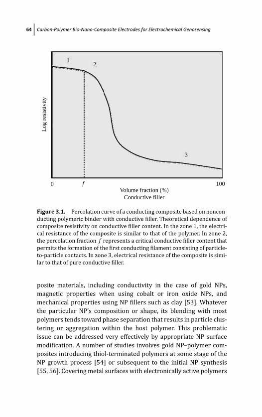
March 19, 2012 17:4 PSP Book - 9in x 6in 03-Ozsoz-c03
64 Carbon-Polymer Bio-Nano-Composite Electrodes for Electrochemical Genosensing
0 100Volume fraction (%)
Conductive filler
f
Log
resi
stiv
ity
12
3
Figure 3.1. Percolation curve of a conducting composite based on noncon-
ducting polymeric binder with conductive filler. Theoretical dependence of
composite resistivity on conductive filler content. In the zone 1, the electri-
cal resistance of the composite is similar to that of the polymer. In zone 2,
the percolation fraction f represents a critical conductive filler content that
permits the formation of the first conducting filament consisting of particle-
to-particle contacts. In zone 3, electrical resistance of the composite is simi-
lar to that of pure conductive filler.
posite materials, including conductivity in the case of gold NPs,
magnetic properties when using cobalt or iron oxide NPs, and
mechanical properties using NP fillers such as clay [53]. Whatever
the particular NP’s composition or shape, its blending with most
polymers tends toward phase separation that results in particle clus-
tering or aggregation within the host polymer. This problematic
issue can be addressed very effectively by appropriate NP surface
modification. A number of studies involves gold NP–polymer com-
posites introducing thiol-terminated polymers at some stage of the
NP growth process [54] or subsequent to the initial NP synthesis
[55, 56]. Covering metal surfaces with electronically active polymers
March 19, 2012 17:4 PSP Book - 9in x 6in 03-Ozsoz-c03
Carbon Composites 65
provides a close proximity of the two materials that facilitate their
electronic communication.
Besides metal NPs, carbon micro and nanoparticles as well as
carbon nanotubes are usually used as fillers in composites for elec-
trochemical transducers. The following section focuses on the prop-
erties and main issues of carbon-polymer conducting composites
based on nonconducting binders and polymers.
3.3 Carbon Composites
3.3.1 Carbon-Based Materials as ConductiveFillers in Composites
Carbon is an ideal choice as composite filler due to its high chem-
ical inertness, wide range of working potentials, low electrical
resistance, and low residual currents. The extraordinary ability of
carbon to combine with itself and other chemical elements in dif-
ferent ways is the basis of organic chemistry. As a consequence,
there is a rich diversity of structural forms of solid carbon because
it can exist as any of the several allotropes. It is found abundantly
in nature as coal, a natural graphite, and also in much less abundant
form as diamond. Engineered carbons [57] are the product of the
carbonization process of a carbon-containing material, conducted
in an oxygen-free atmosphere. Depending on the starting precur-
sor material (hydrocarbon gases, petroleum-derived products, coals,
polymers, biomass), the product of a carbonization process will have
different properties, including the adsorption capability. Traditional
engineered carbons can take many forms, such as coke, graphite, car-
bon and graphite fiber, carbon monoliths, glassy carbon (GC), car-
bon black, carbon film, and diamond-like film [57]. The discovery
of nanostructured carbon-based materials added a new dimension
to the knowledge of carbon science. The first TEM evidence for the
tubular nature of some nanosized carbon filaments, that is, of carbon
nanotubes (MWCNT, multiwalled carbon nanotubes) was reported
in 1952 by Radushkevich and Lukyanovich [58]. The subsequent dis-
covery in the “nano” era of “fullereness” [59] has also impacted the
carbon science. Finally, the growing of SWCNTs was first reported in
March 19, 2012 17:4 PSP Book - 9in x 6in 03-Ozsoz-c03
66 Carbon-Polymer Bio-Nano-Composite Electrodes for Electrochemical Genosensing
1993 by two papers submitted independently, one by Iijima and Ichi-
hashi [60], and the other by Bethune et al. [61]. CNTs can be grown
by using the arc-discharge method, the laser vaporization method,
and the chemical vapor deposition (CVD) [62]. Compared with
arc-discharge and laser methods, CVD is a simple and economic
technique for synthesizing CNTs at low temperature and ambient
pressure, at the cost of crystallinity. It is versatile in that it harnesses
a variety of hydrocarbons in any state (solid, liquid, or gas), enables
the use of various substrates, and allows CNT growth in a variety
of forms, such as powder, thin or thick films, aligned or entangled,
straight or coiled, or even a desired architecture of nanotubes at pre-
defined sites on a patterned substrate. It also offers better control
over growth parameters.
Carbon-based materials have found intensive use as adsorbents
because of their porous and highly developed internal surface areas
as well as their complex chemical structures. The porous struc-
ture and the chemical nature of the carbon surface are signifi-
cantly related to its crystalline constitution. The crystal structure
of graphite consists of parallel layers of condensed, regular hexag-
onal rings. The in-plane C–––C distance is intermediate between the
Csp3–––Csp3 and the Csp2===Csp2 bond lengths. Graphene is the hypo-
thetical infinite aromatic sheet of sp2-bonded carbon that is the 2-D
counterpart of naturally occurring 3-D graphite. It is found in the
π -stacked hexagonal structure of graphite with an interlayer spac-
ing of 3.34 A, which is the van der Waals distance for sp2-bonded
carbon [63].
The pore structure and surface area of carbon-based materials
determine their physical characteristics, while the surface chemi-
cal structure affects interactions with polar and nonpolar molecules
due to the presence of chemically reactive functional groups. Active
sites—edges, dislocations, and discontinuities—determine the reac-
tivity of the carbon surface. Graphitic materials have at least two dis-
tinct types of surface sites, namely, the basal-plane and edge-plane
sites [64]. It is generally considered that the active sites for electro-
chemical reactions are associated with the edge-plane sites, while
the basal plane is mostly inactive. Heteroatoms (usually oxygen)
play an important role in the chemical nature of the carbon “active”
surface [57]. The adsorption process is thus strongly dependent on
March 19, 2012 17:4 PSP Book - 9in x 6in 03-Ozsoz-c03
Carbon Composites 67
the type, quantity, and bonding of these functional groups in the
structure. Heteroatoms distributed randomly in the core of the car-
bon matrix may be nonreactive due to their inaccessibility. How-
ever, the heteroatoms can also be concentrated at the exposed
surface of carbons or presented as an “active” dislocation of the
microcrystalline structure. Much of the research being carried out
is focused not only on the identification and characterization of
oxygen-containing functional groups in oxidized carbon surfaces,
such as carboxyl, phenolic, quinonic, and lactones, but also in the
changes that take place in the carbon surface under different oxida-
tion treatments.
The electrochemical oxidation pretreatment was found to
improve the electrochemical behavior by introducing more active
edge sites on the treated carbon surface. The effect of oxidation
on the chemical composition is related to the increased concentra-
tion of strong and weak acidic groups found upon electrochemi-
cal oxidation of the graphite surface [65]. The acidity of carboxylic
groups on the oxidized carbon surface could be stronger than that
of a carboxylic resin. The weight increase after electrochemical pre-
treatment was attributed to the formation of the oxidized graphite
and the intercalation of solvent molecules and anions into graphitic
material.
Regarding the CNTs, the growing methods provide not only
the CNT product, but also different contaminants (mainly amor-
phous carbon and catalyst metallic particles) which are commonly
removed by treatment with oxidizing acids, for example, HNO3,
which results in ends largely decorated with carboxyl groups [66].
However, defects in the sidewalls can also be introduced under
such drastic conditions. Functionalization or modification of CNTs
has become a major activity within the interdisciplinary fields of
nanoscience, nanotechnology, bioengineering, and bionanotechnol-
ogy, as it promises to be the best approach for improving the sol-
ubility and compatibility of CNTs. Defects in SWNTs are important
in the covalent chemistry of the tubes because they can serve as
anchor groups for further functionalization, and therefore a promis-
ing starting point for the development of the covalent chemistry of
SWNTs [67].
March 19, 2012 17:4 PSP Book - 9in x 6in 03-Ozsoz-c03
68 Carbon-Polymer Bio-Nano-Composite Electrodes for Electrochemical Genosensing
CNTs present a larger surface area and outstanding charge-
transport characteristics and might therefore greatly promote
electron-transfer reactions which can dramatically improve elec-
trochemical performance compared to that of other carbonaceous
materials [68]. The open end of a CNT is expected to show a fast
electron-transfer rate similar to the graphite edge plane while the
sidewall is inert like the graphite basal-plane. Fast electron-transfer
rate is demonstrated along the tube axis [69].
CNTs are expected to present a wide electrochemical window,
flexible surface chemistry, and biocompatibility, similar to other
widely used carbon materials.
Among the different classes of carbon allotropes, carbon-based
composites, such as carbon paste (CP), are usually made of polycrys-
talline graphite. A key property of polycrystalline graphite is poros-
ity. Most polycrystalline graphite—such as powdered carbon—is
made by heat treatment of high-molecular-weight petroleum frac-
tions at high temperatures to perform graphitization. The term
“graphite” is used to designate materials that have been subjected
to high temperatures, and thus have aligned the sp2 planes parallel
to each other.
Commercially available microcrystalline graphite exists as
extremely hydrophobic 1 to 20 μm particles that aggregate into
thin films on contact with solvent. When treated under strongly
oxidizing acidic conditions, graphite oxide is formed. Structurally,
graphite oxide is an epoxidized form of the sp2-bonded carbon net-
work together with acidic functional groups at the edges with the
oxidants intercalated in the interlaminar space [63].
While the electrical conductivity is provided by the conducting
carbonaceous filler, in order to prepare a carbon composite, a binder
is also needed. The binder will confer the conducting composite a
certain physical, chemical, or biological stability. One of the sim-
plest carbon composite approaches for electrochemical biosensor
is based on soft carbon pastes [70]. These pastes are built by mix-
ing an inert conductor (e.g., graphite powder) with a nonconducting
liquid (e.g., paraffin oil, silicone, Nujol). This insulating liquid has a
specific viscosity and the paste has a certain consistency. The result-
ing devices are easy to prepare and inexpensive. However, these
pastes have limited mechanical and physical stability, especially in
March 19, 2012 17:4 PSP Book - 9in x 6in 03-Ozsoz-c03
Carbon Composites 69
flow systems. Additionally, the pastes are dissolved by some nonpo-
lar electrolytic solvents, leading to a deterioration of the signal. The
general degradation of these devices occurs quickly and has limited
their use to the research laboratory [18]. Unlike soft carbon paste,
rigid carbon polymer composites allow the design of different con-
figurations, and these materials are compatible with nonaqueous
solvents. Next section is focused in the preparation and properties
of rigid carbon polymer composites.
3.3.2 Rigid Carbon-Polymer Composite
Rigid carbon-polymer composites are obtained by mixing a car-
bon filler (such as graphite or CNT) with nonconducting polymeric
binders (epoxy, methacrylate, silicone, araldite), obtaining a soft
paste that becomes rigid after a curing step.
Rigid carbon-polymer composites are interesting alternatives for
the construction of electrochemical (bio)sensors. The capability of
integrating various materials (including nanostructured particles
and biomolecules) is one of their main advantages. Some materi-
als which are incorporated within the composite result in enhanced
sensitivity and selectivity. The best composite components will give
the resulting material improved chemical, physical, and mechani-
cal properties. As such, it is possible to choose between different
binders and polymeric matrices and conductive fillers in order to
obtain a better signal-to-noise ratio, a lower non-specific adsorption,
and improved electrochemical properties (electron transfer rate and
electrocatalytic behavior). This incorporation is possible to be per-
formed either through a previous modification of one of the com-
ponent of the composite before its preparation or through physical
incorporation into the composite matrix.
The electrical resistance is determined by the connectivity of
the conducting particles inside the nonconducting matrix; there-
fore, the relative amount of each composite component has to
be assessed to achieve optimal composition. Figure 3.2 shows
scanning electron micrographs of different carbon-based materi-
als based on the same conductive filler (graphite) but different
polymeric binders: (A) Araldite-M–graphite (73.2%), (B) Araldite-
CW2215–graphite (45.8%), (C) silicone–graphite (61.0%), (D)
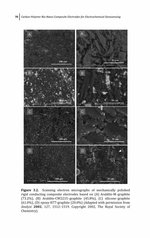
March 19, 2012 17:4 PSP Book - 9in x 6in 03-Ozsoz-c03
70 Carbon-Polymer Bio-Nano-Composite Electrodes for Electrochemical Genosensing
Figure 3.2. Scanning electron micrographs of mechanically polished
rigid conducting composite electrodes based on (A) Araldite-M–graphite
(73.2%), (B) Araldite-CW2215–graphite (45.8%), (C) silicone–graphite
(61.0%), (D) epoxy-H77-graphite (20.0%) (Adapted with permission from
Analyst 2002, 127, 1512–1519. Copyright 2002, The Royal Society of
Chemistry).
March 19, 2012 17:4 PSP Book - 9in x 6in 03-Ozsoz-c03
Carbon Composites 71
epoxy-H77–graphite (20%). The optimal composition in each case
was obtained from the percolation curve [52]. As shown in the scan-
ning electron micrographs, completely different materials have been
obtained with different polymeric binders. Moreover, the polymeric
binders accept different “optimal” amount of graphite.
Being in the nanotechnology era, novel nanostructured compos-
ite materials are expected to be designed showing improved proper-
ties due to nanostructuration. Moreover, composite electrodes from
expensive metals (gold, platinum, etc.) can be prepared using the
NPs as conductive fillers, with enhanced properties but at lower
prices compared to their pure conductor counterparts.
Rigid carbon-polymer composite electrodes offer many potential
advantages compared to more traditional electrodes consisting of
a surface-modified continuous conducting material. Rigid carbon-
polymer composite electrodes can often be fabricated with great
flexibility in size and shape, allowing the construction of different
electrode configurations. Rigid composite surfaces can be smoothed
or polished to provide fresh active material ready to be used in a
new assay. Each new surface yields reproducible results because
all individual compounds are homogeneously dispersed in the bulk
of the composite. Moreover, rigid carbon-polymer composites show
improved electrochemical performances, similar to an array of car-
bon fibers separated by an insulating matrix and connected in paral-
lel. The signal produced by this macroelectrode formed by a carbon
fiber ensemble is the sum of the signals of the individual microelec-
trodes. Composite electrodes thus showed a higher signal-to-noise
(S/N) ratio than the corresponding pure conductors, accompanied
by an improved electrochemical behavior [46].
3.3.3 Graphite-Epoxy Composites
Rigid conducting graphite-epoxy composites (GEC) [25, 35, 36] and
biocomposites (GEB) [18, 23] have been extensively used in our
laboratories for electrochemical (bio)sensing due to their unique
physical and electrochemical properties. In particular, we have used
GEC (graphite-epoxy composite) made by mixing the nonconduct-
ing epoxy resin (Epo-Tek, Epoxy Technology, Billerica, MA, USA) with
graphite microparticles (particle size below 50 μm).
March 19, 2012 17:4 PSP Book - 9in x 6in 03-Ozsoz-c03
72 Carbon-Polymer Bio-Nano-Composite Electrodes for Electrochemical Genosensing
This paste can be easily prepared by mixing graphite powder
with epoxy resin in a 1:4 (w/w) ratio. The soft paste is thoroughly
hand mixed to ensure the uniform dispersion of the graphite pow-
der throughout the polymer. The moldable soft paste is put on the
body of the electrodes and cured at 100◦C for 2 days to obtain
the rigid graphite-epoxy composite (GEC) [25]. A magneto graphite-
epoxy composite (m-GEC) electrode is prepared in the same way as
the GEC transducer, but in this case, a small magnet (3 mm i.d.) is
placed in the center of this electrode after the addition of a thin layer
of GEC paste in order to avoid the direct contact between the mag-
net and the electrical connector. After filling the electrode body gap
completely with the soft paste, the electrode is tightly packed and
then cured at the same temperature. This magneto electrode can be
easily coupled with magnetic particles [71, 72].
Biocomposites can also be easily prepared by adding the biore-
ceptor (an enzyme [18] and antibody [23], or an affinity receptor
such as Protein A [73] or avidin [74, 75]).
As an example, in the case of avidin graphite-epoxy biocomposite
(Av-GEB), graphite powder and epoxy resin are also hand mixed in
a ratio of 1:4 (w/w). In this case, for every gram of graphite/epoxy
mixture, an additional 20 mg of avidin is added—resulting in a 2%
(w/w) avidin-graphite-epoxy biocomposite. This mixture is thor-
oughly hand mixed to ensure the uniform dispersion of the avidin
and carbon throughout the polymer. The moldable soft paste is put
on the body of the electrodes and cured at 40◦C for 1 week to obtain
the rigid avidin-graphite-epoxy biocomposite (Av-GEB).
Finally, gold nanocomposites are prepared by hand-mixing the
following ratios of gold-NPs, graphite powder, and epoxy resin:
0.075/0.925/4 (w/w) for nanoAu(7.5%)-GEC. The resulting soft
paste is placed in the gap of electrode and cured at 80◦C for 1 week to
obtain the rigid gold NPs graphite-epoxy composite (nanoAu-GEC).
The GEC-based transducers present numerous advantages over
more traditional carbon-based materials: higher sensitivity, robust-
ness, and rigidity. Additionally, the surface of GEC can be regenerated
by a simple polishing procedure.
An ideal material for electrochemical genosensing should allow
an effective immobilization of the probe on its surface, a robust
hybridization of the target with the probe, a negligible non-specific

March 19, 2012 17:4 PSP Book - 9in x 6in 03-Ozsoz-c03
Electrochemical Genosensing Based on Graphite-Epoxy Composite 73
adsorption of the label and a sensitive detection of the hybridiza-
tion event. Graphite-epoxy composites (GEC) fulfill all these require-
ments.
In the present work, graphite-epoxy composite, biocomposite,
and nanocomposite materials for the development of electrochem-
ical genosensors are reviewed. Different graphite-epoxy platforms
for electrochemical genosensing, as well as strategies for detect-
ing DNA hybridization are presented. The advantages of these new
graphite-epoxy platforms for electrochemical genosensing are dis-
cussed and compared with the current state of the art in DNA sens-
ing techniques.
3.4 Electrochemical Genosensing Based onGraphite-Epoxy Composite
3.4.1 Electrochemical Genosensing Based on DNADry Adsorption on GEC as ElectrochemicalTransducer
Adsorption is an easy way to attach nucleic acids to solid surfaces,
since no reagents or modified-DNA are required, as shown in Fig. 3.3.
These features have promoted extensive use of adsorption as immo-
bilization methodology in genetic analysis. The mainly claimed dis-
advantages of adsorption with respect to covalent immobilization
are (i) nucleic acids may be readily desorbed from the substrate and
(ii) base moieties may be unavailable for hybridization if they are
bonded to the substrate in multiple sites [76]. However, the electro-
chemical detection strategy based on the intrinsic oxidation of DNA
requires the DNA to be adsorbed in close contact with the electro-
chemical substrate by multisite attachment, as schematically shown
in Fig. 3.4. This multisite attachment of DNA can be thus detrimen-
tal for its hybridization but is crucial for the detection based on its
oxidation signals. The common method for the multisite physical
adsorption of DNA on carbonaceous-based materials can be classi-
fied into dry or wet adsorptions.
Dry adsorption relies on leaving DNA to dry on the carbonaceous
surface. It can be assisted by light treatment (except UV that is able
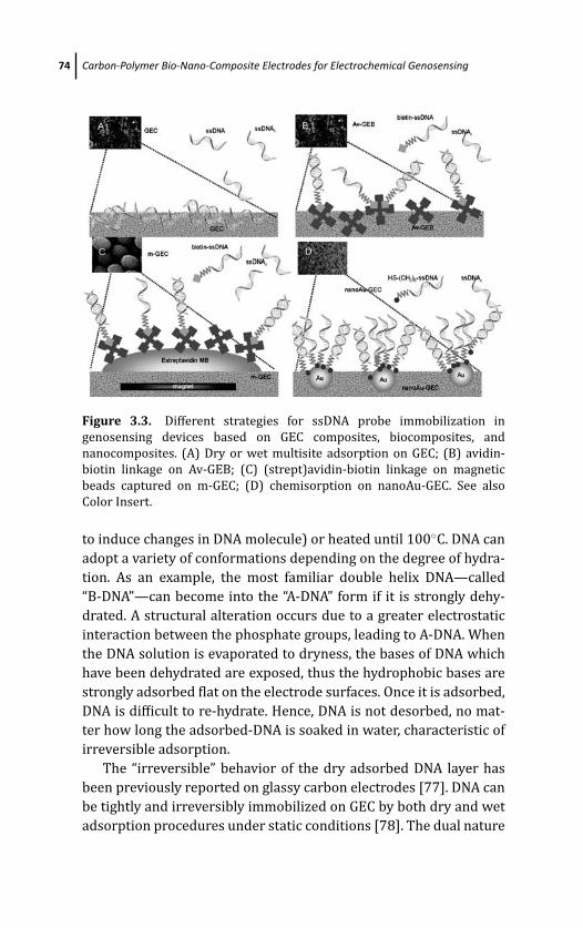
March 19, 2012 17:4 PSP Book - 9in x 6in 03-Ozsoz-c03
74 Carbon-Polymer Bio-Nano-Composite Electrodes for Electrochemical Genosensing
Figure 3.3. Different strategies for ssDNA probe immobilization in
genosensing devices based on GEC composites, biocomposites, and
nanocomposites. (A) Dry or wet multisite adsorption on GEC; (B) avidin-
biotin linkage on Av-GEB; (C) (strept)avidin-biotin linkage on magnetic
beads captured on m-GEC; (D) chemisorption on nanoAu-GEC. See also
Color Insert.
to induce changes in DNA molecule) or heated until 100◦C. DNA can
adopt a variety of conformations depending on the degree of hydra-
tion. As an example, the most familiar double helix DNA—called
“B-DNA”—can become into the “A-DNA” form if it is strongly dehy-
drated. A structural alteration occurs due to a greater electrostatic
interaction between the phosphate groups, leading to A-DNA. When
the DNA solution is evaporated to dryness, the bases of DNA which
have been dehydrated are exposed, thus the hydrophobic bases are
strongly adsorbed flat on the electrode surfaces. Once it is adsorbed,
DNA is difficult to re-hydrate. Hence, DNA is not desorbed, no mat-
ter how long the adsorbed-DNA is soaked in water, characteristic of
irreversible adsorption.
The “irreversible” behavior of the dry adsorbed DNA layer has
been previously reported on glassy carbon electrodes [77]. DNA can
be tightly and irreversibly immobilized on GEC by both dry and wet
adsorption procedures under static conditions [78]. The dual nature
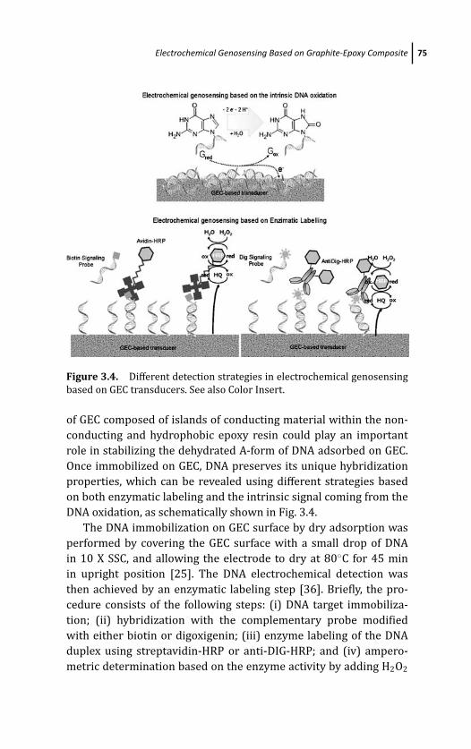
March 19, 2012 17:4 PSP Book - 9in x 6in 03-Ozsoz-c03
Electrochemical Genosensing Based on Graphite-Epoxy Composite 75
Figure 3.4. Different detection strategies in electrochemical genosensing
based on GEC transducers. See also Color Insert.
of GEC composed of islands of conducting material within the non-
conducting and hydrophobic epoxy resin could play an important
role in stabilizing the dehydrated A-form of DNA adsorbed on GEC.
Once immobilized on GEC, DNA preserves its unique hybridization
properties, which can be revealed using different strategies based
on both enzymatic labeling and the intrinsic signal coming from the
DNA oxidation, as schematically shown in Fig. 3.4.
The DNA immobilization on GEC surface by dry adsorption was
performed by covering the GEC surface with a small drop of DNA
in 10 X SSC, and allowing the electrode to dry at 80◦C for 45 min
in upright position [25]. The DNA electrochemical detection was
then achieved by an enzymatic labeling step [36]. Briefly, the pro-
cedure consists of the following steps: (i) DNA target immobiliza-
tion; (ii) hybridization with the complementary probe modified
with either biotin or digoxigenin; (iii) enzyme labeling of the DNA
duplex using streptavidin-HRP or anti-DIG-HRP; and (iv) ampero-
metric determination based on the enzyme activity by adding H2O2
March 19, 2012 17:4 PSP Book - 9in x 6in 03-Ozsoz-c03
76 Carbon-Polymer Bio-Nano-Composite Electrodes for Electrochemical Genosensing
and using hydroquinone as a mediator. If the PCR product—or any
other double-stranded DNA—is directly adsorbed on GEC trans-
ducer, a denaturing alkaline procedure after the DNA dry adsorption
is mandatory to break the hydrogen bonds linking the comple-
mentary DNA strands in order to ensure proper hybridization
[79].
Although a compact thick ssDNA layer can be achieved by
dry adsorption, DNA preserves its unique hybridization properties,
which can be monitored using different strategies, suggesting that
the DNA bases are not fully committed in the adsorption mechanism.
DNA bases are mostly available for hybridization, taking into account
the differences in signal compared with the non-specific adsorption
[79, 80]. This strategy was able to electrochemically detect the PCR
amplicon coming from Salmonella spp. in a very simple and cheap
way [79].
Besides this strategy in which the DNA target can be easily
attached and detected by its complementary DNA signaling probe,
a sandwich assay in which the DNA target is in solution can be
easily performed by a double hybridization with a capture and a
signaling probe [25]. This strategy was demonstrated to be use-
ful for the detection of a novel determinant of β-lactamase resis-
tance in S. aureus using one- and two-step capture format. Accord-
ing to the results, the one-step capture format is more convenient,
as a higher sensitivity was achieved [25]. When compared with
other reported genosensor designs using a similar capture format
[81] and the same labeling system, the genosensor design based on
dry adsorption is simpler and cheaper, showing detection limits of
the same order of magnitude. The procedures based on previous
activation/modification of the surface transducer and subsequent
immobilization, as well as some blocking and washing steps that are
tedious, expensive, and time-consuming, were avoided using GEC as
electrochemical platform. These are the principal advantages of GEC
platform with respect to other reported devices [37, 81, 82].
Moreover, by easily controlling the concentration of the DNA
solution being dried on GEC platform, a thick or a thin layer of DNA
can be formed on the GEC surface by dry adsorption [36]. Depend-
ing on the application of the DNA-modified substrate, a thick or thin
DNA layer would be necessary. If a stringency control of non-specific
March 19, 2012 17:4 PSP Book - 9in x 6in 03-Ozsoz-c03
Electrochemical Genosensing Based on Graphite-Epoxy Composite 77
DNA adsorption issues is required, a thick DNA layer is more con-
venient. However, the yield in hybridization is better on a thin DNA
layer [36].
Furthermore, GEC has shown unique and selective adsorption
behavior. While DNA is firmly adsorbed under dry conditions, the
wet adsorption of non-specific DNA, proteins, enzymes, or other
biomolecules is negligible under stirring or convection conditions
in solution [25, 79, 80]. The DNA-modified GEC surface does not
require blocking steps to minimize the non-specific adsorption on
the free sites of the surface [36] since the non-specific adsorp-
tion is very low and similar to the instrumental background noise.
Moreover, no blocking reagents are required during hybridization
to reduce the non-specific adsorption. It was previously demon-
strated that the hybridization signals (as well as the non-specific
adsorption signals) were essentially the same when performing the
hybridization without blocking reagents and using different block-
ing commercial solution, such as (i) 5XSSC, 1XDenhardt’s, 100 μg/ml
chloroform extracted salmon testes DNA, 0.5% (w/v), SDS and 50%
(v/v) formamide; (ii) 5XSSC, 1XDenhardt’s, 0.5% (w/v) SDS and
50% (v/v) formamide; and (iii) 5XSSC, 0.5% (w/v) SDS and 50%
(v/v) formamide. Comparable hybridization signals as well as non-
specific adsorption are achieved by using those three different solu-
tions for hybridization [25].
3.4.2 Electrochemical Genosensing Based on DNAWet Adsorption on GEC as ElectrochemicalTransducer
Wet adsorption relies on leaving DNA to interact with the carbona-
ceous surface through physical forces in the presence of water. Dur-
ing wet adsorption, the stabilization of B-DNA is expected to occur
on the carbonaceous surface, by keeping the hydration water of the
DNA molecule. In this case, the hydrated B-DNA form is stabilized
over the GEC surface by weaker forces: as the water is kept on the
DNA adsorbed molecule, it can be easily desorbed from the GEC sur-
face if soaked in aqueous solutions.
DNA can be easily immobilized on GEC by simple wet adsorption
onto GEC surface. A small drop of DNA probe in acetate saline
March 19, 2012 17:4 PSP Book - 9in x 6in 03-Ozsoz-c03
78 Carbon-Polymer Bio-Nano-Composite Electrodes for Electrochemical Genosensing
solution pH 4.8 [25] is put onto the surface of a GEC electrode in
an upright position. The immobilization of the probe was allowed
to proceed for 15 min without applying any potential under static
conditions.
After the inosine-modified DNA probe immobilization, the DNA
target was detected by the intrinsic DNA oxidation signal coming
from the guanine moieties, as schematically outlined in Fig. 3.4.
Briefly, the procedure consists of the following four steps: [83] (i)
electrochemical pre-treatment of the GEC transducer; (ii) inosine-
substituted probe immobilization by wet adsorption on GEC trans-
ducer; (iii) hybridization with the target; and (iv) electrochemical
determination based on differential pulse voltammetry (DPV), in
which the oxidation signal of guanine (or adenine) was measured
by scanning from +0.30 to +1.20V at a pulse amplitude of 100 mV
and a scan rate of 15 mV/s. This procedure was demonstrated to be
useful for the detection of IS200 element specific for Salmonella spp.
[83].
Although a thick or a thin layer of DNA can be attached on the
surface during dry adsorption by controlling the concentration of
the DNA solution being dried, the wet adsorption normally yields
a thin DNA layer. Less compact DNA layers with wider gaps exposing
free-GEC surface are normally obtained during wet adsorption. As
a consequence, the thin-layer DNA/GEC surface required blocking
treatment to avoid non-specific adsorption. During wet adsorption,
the substrate is progressively modified with negative charges com-
ing from the DNA being adsorbed; thus, rejecting the successive DNA
molecules that are approaching the substrate. Wet adsorption thus
leads to a “self-control” surface coverage and is less stringent than
dry adsorption [25].
3.4.3 Electrochemical Genosensing Based onGraphite-Epoxy Biocomposite Modified with Avidin(Av-GEB) as Electrochemical Transducer
A rigid and renewable transducing material for electrochemical
biosensing, based on avidin bulk-modified graphite–epoxy biocom-
posite (Av-GEB), can be easily prepared by adding a 2% avidin
(or streptavidin) in the formulation of the composite and using
March 19, 2012 17:4 PSP Book - 9in x 6in 03-Ozsoz-c03
Electrochemical Genosensing Based on Graphite-Epoxy Composite 79
dry chemistry techniques, avoiding tedious, expensive, and time-
consuming immobilization procedures. The rigid conducting bio-
composite acts not only as a transducer but also as a reservoir for
avidin. After use, the electrode surface can be renewed by a simple
polishing procedure for further uses, highlighting a clear advantage
of this new material with respect to surface-modified approaches
such as classical biosensors and other common biological assays.
DNA probe can be easily immobilized on the surface of the avidin-
modified transducer through the avidin–biotin reaction, since both
nucleic acids as well as short oligonucleotides can be readily linked
to biotin without serious effects on their biological, chemical, or
physical properties (Fig. 3.3B). The knowledge about the avidin–
biotin interaction has advanced significantly and offers an extremely
versatile tool. Moreover, this interaction presents a variety of specific
advantages over other single-point immobilization techniques. In
particular, the extremely specific and high affinity reaction between
biotin and the glycoprotein avidin (association constant Ka = 1015)
leads to strong associations similar to the formation of a cova-
lent bonding. This interaction is highly resistant to a wide range of
chemicals (detergents, protein denaturants), pH range variations,
and high temperatures [84]. In addition, much progress has been
done in the modification of biomolecules with biotin. Moreover, the
strept(avidin) could be considered as a universal affinity biomole-
cule because it is able to link not only biotinylated DNA or ODNs but
also enzymes or antibodies [23].
Biotinylated DNA can be firmly single-point attached in Av-
GEB (Fig. 3.3B). In this case, a capture format was used in which
the immobilization of the biotinylated probe together with the
hybridization was performed in a one-step procedure [74]. Briefly,
the three-step experimental procedure consists of (i) one-step
immobilization/hybridization procedure in which the biotin-labeled
capture probe is immobilized onto the electrode surface through
a biotin–avidin interaction, while the hybridization with the target
and with a second complementary probe—in this case labeled with
digoxigenin—is occurring at the same time; (ii) enzymatic labeling
using as enzyme label the antibody anti-DIG-HRP; and (iii) ampero-
metric determination based on the enzyme activity by adding H2O2
and using hydroquinone as a mediator.
March 19, 2012 17:4 PSP Book - 9in x 6in 03-Ozsoz-c03
80 Carbon-Polymer Bio-Nano-Composite Electrodes for Electrochemical Genosensing
The utility of Av-GEB platform was demonstrated for the deter-
mination of the mecA DNA sequence related with methicillin-
resistant S. aureus (MRSA) [85] in a simpler and specific manner
with respect to previous DNA biosensing devices [25].
The genosensor design based on Av-GEB not only is able to
successfully immobilize onto the electrode surface with the mecA
biotin-labeled capture probe, while the hybridization with the mecA
target and the mecA digoxigenin-labeled probe is occurring at the
same time, but is also capable of distinguishing SNPs.
Compared to genosensors based on GEC, the novelty of this
approach is in part attributed to the simplicity of its design, com-
bining the hybridization and the immobilization of DNA in one ana-
lytical step.
The optimum time for the one-step immobilization/
hybridization procedure was found to be 60 min [74]. The pro-
posed DNA biosensor design has proven to be successful in using
a simple bulk modification step; hence, overcoming the complicated
pre-treatment steps associated with other DNA biosensor designs.
Additionally, the use of a one-step immobilization and hybridiza-
tion procedure reduces the experimental time. Stability studies con-
ducted demonstrate the capability of the same electrode to be used
for a 12-week period [74].
The rapid electrochemical verification of the amplicon com-
ing from the Escherichia coli O157:H7 genome was performed by
double-labeling the amplicon during PCR with a set of two labeled
PCR primers—one of them with biotin and the other one with digox-
igenin. During PCR, not only the amplification of the E. coli was
achieved but also the double-labeling of the amplicon ends with (i)
the biotinylated capture primer to achieve the immobilization on a
biosensor based on a bulk-modified avidin biocomposite (Av-GEB)
and (ii) the digoxigenin signaling primer to achieve the electrochem-
ical detection. The procedure consisted briefly of the following steps:
(i) DNA amplification and double-labeling of the eaeA gene, related
with the pathogenic activity of Escherichia coli O157:H7; (ii) immobi-
lization of the doubly labeled amplicon in which the biotin extreme
of the dsDNA amplicon was immobilized on the Av-GEB biosensor;
(iii) enzymatic labeling with anti-DIG-HRP capable of bonding with
the other labeled extreme of the dsDNA amplicon; and (iv) ampero-
metric determination [75].
March 19, 2012 17:4 PSP Book - 9in x 6in 03-Ozsoz-c03
Electrochemical Genosensing Based on Graphite-Epoxy Composite 81
3.4.4 Electrochemical Genosensing Based on MagneticBeads and m-GEC Electrochemical Transducer
One of the most promising materials, which have been developed, is
biologically modified magnetic beads [86] based on the concept of
magnetic bioseparations. Magnetic beads offer some new attractive
possibilities in biomedicine and bioanalysis since their size is com-
parable to those of cells. Moreover, they can be coated with biological
molecules and they can also be manipulated by an external mag-
netic field gradient. As such, the biomaterial, specific cells, proteins,
or DNA, can be selectively bound to the magnetic beads and then
separated from its biological matrix by using an external magnetic
field. Moreover, magnetic beads of a variety of materials and sizes,
and modified with a wide variety of surface functional groups, are
now commercially available. They have brought novel capabilities
to electrochemical immunosensing [87–89]. The magnetic beads
have also been used in novel electrochemical genosensing protocols
[90]. These approaches using magnetic beads for detection of DNA
hybridization have been combined with different strategies for the
electrochemical detection, such as label-free genosensing [91–93]
or different external labels, such as enzymes [90], electrochemical
indicators [94], or metal tags, for example, gold or silver NPs [95],
and using different electrochemical techniques, such as DPV, poten-
tiometric stripping analysis (PSA), or square wave voltammetry
(SWV).
Instead of the direct modification of the electrode surface, the
biological reactions (as immobilization, hybridization, enzymatic
labeling, or affinity reactions) and the washing steps can be suc-
cessfully performed on magnetic beads. After the modifications, the
magnetic beads can be easily captured by magnetic forces onto the
surface of GEC electrodes holding a small magnet inside (m-GEC).
Once immobilized on m-GEC, the hybridization performed on the
magnetic beads can be electrochemically revealed using different
strategies based on both enzymatic labeling and the intrinsic sig-
nal coming from the DNA oxidation [96] (as shown in Fig. 3.4).
In the case of using magnetic beads, a single-point immobilization
procedure based on streptavidin–biotin interaction is performed
(Fig. 3.3C). Biotinylated DNA can be firmly attached on streptavidin-
modified magnetic beads in that way.
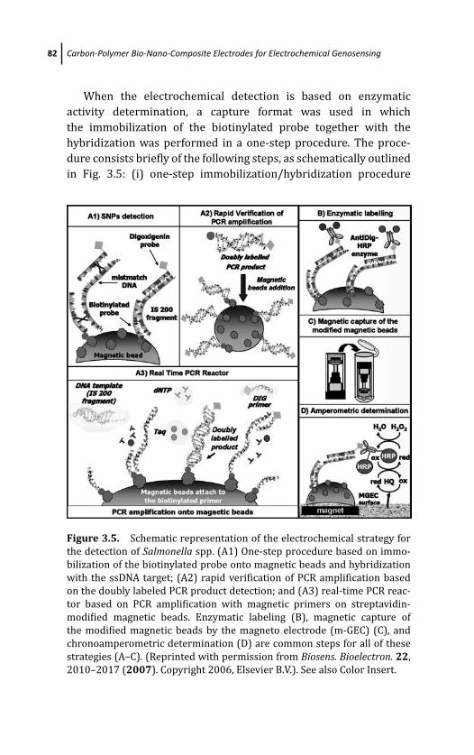
March 19, 2012 17:4 PSP Book - 9in x 6in 03-Ozsoz-c03
82 Carbon-Polymer Bio-Nano-Composite Electrodes for Electrochemical Genosensing
When the electrochemical detection is based on enzymatic
activity determination, a capture format was used in which
the immobilization of the biotinylated probe together with the
hybridization was performed in a one-step procedure. The proce-
dure consists briefly of the following steps, as schematically outlined
in Fig. 3.5: (i) one-step immobilization/hybridization procedure
Figure 3.5. Schematic representation of the electrochemical strategy for
the detection of Salmonella spp. (A1) One-step procedure based on immo-
bilization of the biotinylated probe onto magnetic beads and hybridization
with the ssDNA target; (A2) rapid verification of PCR amplification based
on the doubly labeled PCR product detection; and (A3) real-time PCR reac-
tor based on PCR amplification with magnetic primers on streptavidin-
modified magnetic beads. Enzymatic labeling (B), magnetic capture of
the modified magnetic beads by the magneto electrode (m-GEC) (C), and
chronoamperometric determination (D) are common steps for all of these
strategies (A–C). (Reprinted with permission from Biosens. Bioelectron. 22,
2010–2017 (2007). Copyright 2006, Elsevier B.V.). See also Color Insert.
March 19, 2012 17:4 PSP Book - 9in x 6in 03-Ozsoz-c03
Electrochemical Genosensing Based on Graphite-Epoxy Composite 83
in which the biotin-labeled capture probe is immobilized on the
streptavidin magnetic beads, while the hybridization with the tar-
get and with a second complementary probe—in this case labeled
with digoxigenin—is occurring at the same time (30 min at 42◦C)
(Fig. 3.5, A1); (ii) enzymatic labeling using as enzyme label the
antibody anti-DIG-HRP (Fig. 3.5, B); (iii) magnetic capture of the
modified magnetic particles (Fig. 3.5, C); and (iv) amperometric
determination based on the enzyme activity by adding H2O2 and
using hydroquinone as a mediator (Fig. 3.5, D) [97]. When the
DNA target immobilized on the magnetic beads was detected by
the intrinsic DNA oxidation signal coming from the guanine moi-
eties, the procedure consists of the following steps, as previously
described in detail [96]: (i) electrochemical pre-treatment of the m-
GEC transducer; (ii) biotinylated inosine-substituted probe immobi-
lization on streptavidin magnetic beads; (iii) hybridization with the
target; (iv) magnetic capture of the modified magnetic particles, fol-
lowed by dry adsorption, was performed during 45 min at 80◦C; and
(v) electrochemical determination based on DPV.
The procedure for electrochemical DNA biosensing based on
magnetic beads was also used for the detection of IS200 element
specific for Salmonella spp.
This new electrochemical genomagnetic strategy using magneto
electrodes in connection with magnetic particles offers many poten-
tial advantages compared to more traditional strategies for detecting
DNA.
This new strategy takes advantages of working with magnetic
particles, such as improved and more effective biological reactions,
washing steps, and magnetic separation after each step. This elec-
trochemical genomagnetic assay provides much sensitive, rapid, and
cheaper detection than other assays previously reported. This sen-
sitivity of the GEC with respect to other electrochemical transducer
and selectivity conferred by the magnetic separation were also used
for the detection of PCR amplicons coming from real samples.
The rapid electrochemical verification of the amplicon com-
ing from the Salmonella IS200 element [97] as well as the eaeAgene, related with Escherichia coli O157:H7 [75] was performed
by double-labeling the amplicon during PCR with a set of two
labeled PCR primers—one of them with biotin and the other one
March 19, 2012 17:4 PSP Book - 9in x 6in 03-Ozsoz-c03
84 Carbon-Polymer Bio-Nano-Composite Electrodes for Electrochemical Genosensing
with digoxigenin. During PCR, not only the amplification of the
bacteria genome is achieved but also the double-labeling of the
amplicon ends with (i) the biotinylated capture primer to achieve
the immobilization on the streptavidin-modified magnetic bead,
and (ii) the digoxigenin signaling primer to achieve the electro-
chemical detection. Besides this double-labeling PCR strategy, a
single-labeling PCR strategy with a further confirmation of the
amplicon by its hybridization was achieved by performing the PCR
with the biotin primer and a further hybridization step with a digoxi-
genin probe. The procedure consists briefly of the following steps, as
schematically outlined in Fig. 3.5: (i) DNA amplification and double-
labeling of Salmonella IS200 insertion sequence; (ii) immobiliza-
tion of the doubly labeled amplicon in which the biotin extreme of
the dsDNA amplicon was immobilized on the streptavidin magnetic
beads (Fig. 3.5, A2); (iii) enzymatic labeling using as enzyme label
the antibody anti-DIG-HRP capable of bonding the other labeled
extreme of the dsDNA amplicon (Fig. 3.5, B); (iv) magnetic capture of
the modified magnetic particles (Fig. 3.5, C); and (v) amperometric
determination (Fig. 3.5, D) [97].
Moreover, a PCR reactor for real-time electrochemical detec-
tion was also designed (Fig. 3.5, A3). In this case, the amplifica-
tion and double-labeling is performed directly on the streptavidin
magnetic beads by using “magnetic bead primers” [97]. The proce-
dure consists briefly of the following steps: (i) in situ DNA amplifi-
cation and double-labeling of Salmonella IS200 insertion sequence
on streptavidin-modified magnetic beads by using a magnetic bead
primer (Fig. 3.5, A3); (ii) enzymatic labeling using as enzyme label
the antibody anti-DIG-HRP capable of bonding the other labeled
extreme of the dsDNA amplicon (Fig. 3.5, B); (iii) magnetic capture of
the modified magnetic particles (Fig. 3.5, C); and (iv) amperometric
determination (Fig. 3.5, D).
The rapid and sensitive verification of the PCR amplicon related
with Salmonella can be achieved with 2.8 fmol of amplified product
[97]. In the case of E. coli the assay showed to be very sensitive, being
able to detect 0.45 ng μl−1 of the original bacterial genome after only
10 cycles of PCR amplification [75]. Moreover, the electrochemical
strategies for the detection of the amplicon showed to be more sen-
sitive compared with Q-PCR strategies based on fluorescent labels
such as TaqMan probes.

March 19, 2012 17:4 PSP Book - 9in x 6in 03-Ozsoz-c03
Electrochemical Genosensing Based on Graphite-Epoxy Composite 85
This strategy can be used for the electrochemical real-time quan-
tification of amplicon since a linear relationship with the amount of
amplified product was obtained [75]. Moreover, this strategy is use-
ful only when a unique and specific band is observed by gel elec-
trophoresis, because of the high specificity of the set of primer being
used in the PCR for the amplification of the bacteria genome. On
the contrary, if the set of primers amplifies not only the sequence of
interest but also other non-specific fragments, it is necessary to con-
firm the internal sequence of the amplicon by a second hybridiza-
tion with a digoxigenin signaling probe. In this case, a single
labeling with biotin during PCR was performed followed by a further
selective hybridization with a digoxigenin signaling probe. More-
over, magnetic bead primers were used for in situ amplification on
magnetic beads of the Salmonella genome and for further electro-
chemical detection of the amplified product. The DNA amplification
on magnetic beads by using the magnetic bead primer with electro-
chemical detection of the amplified product demonstrated to be an
alternative strategy to the classic detection systems. This strategy
was also easily adapted to an immunoseparation step of the bacteria
to improve the LOD for detecting pathogenic bacteria [98].
The procedure consisted briefly of the following steps, as
schematically outlined in Fig. 3.6: (i) immunomagnetic separation of
the bacteria from food samples (Fig. 3.6A); (ii) lysis of the bacteria
and DNA separation (Fig. 3.6B); (iii) DNA amplification and double-
labeling of Salmonella IS200 insertion sequence (Fig. 3.6C); (iv)
immobilization of the doubly labeled amplicon in which the biotin
extreme of the dsDNA amplicon was immobilized on the strepta-
vidin magnetic beads (Fig. 3.6D); (v) enzymatic labeling using as
enzyme label the antibody anti-DIG-HRP capable of bonding the
other labeled extreme of the dsDNA amplicon; (vi) magnetic capture
of the modified magnetic particles; and (vii) amperometric determi-
nation [98].
In this approach, the bacteria are captured and preconcentrated
from food samples with magnetic beads by immunological reac-
tion with the specific antibody against Salmonella. After the lysis
of the captured bacteria, further amplification of the genetic mate-
rial by PCR with a double-tagging set of primers is performed to
confirm the identity of the bacteria. Both steps are rapid alter-
natives to the time-consuming classical selective enrichment and
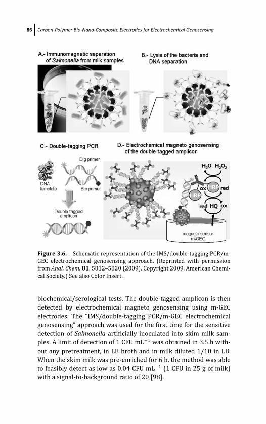
March 19, 2012 17:4 PSP Book - 9in x 6in 03-Ozsoz-c03
86 Carbon-Polymer Bio-Nano-Composite Electrodes for Electrochemical Genosensing
Figure 3.6. Schematic representation of the IMS/double-tagging PCR/m-
GEC electrochemical genosensing approach. (Reprinted with permission
from Anal. Chem. 81, 5812–5820 (2009). Copyright 2009, American Chemi-
cal Society.) See also Color Insert.
biochemical/serological tests. The double-tagged amplicon is then
detected by electrochemical magneto genosensing using m-GEC
electrodes. The “IMS/double-tagging PCR/m-GEC electrochemical
genosensing” approach was used for the first time for the sensitive
detection of Salmonella artificially inoculated into skim milk sam-
ples. A limit of detection of 1 CFU mL−1 was obtained in 3.5 h with-
out any pretreatment, in LB broth and in milk diluted 1/10 in LB.
When the skim milk was pre-enriched for 6 h, the method was able
to feasibly detect as low as 0.04 CFU mL−1 (1 CFU in 25 g of milk)
with a signal-to-background ratio of 20 [98].
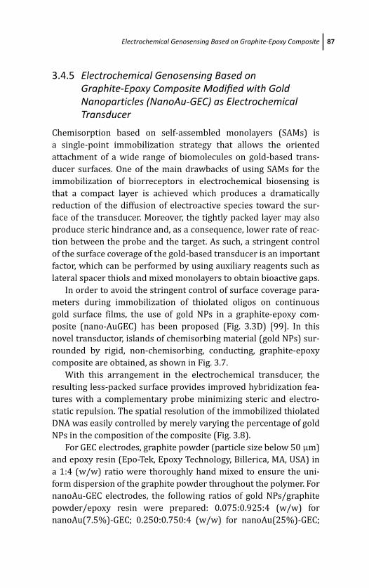
March 19, 2012 17:4 PSP Book - 9in x 6in 03-Ozsoz-c03
Electrochemical Genosensing Based on Graphite-Epoxy Composite 87
3.4.5 Electrochemical Genosensing Based onGraphite-Epoxy Composite Modified with GoldNanoparticles (NanoAu-GEC) as ElectrochemicalTransducer
Chemisorption based on self-assembled monolayers (SAMs) is
a single-point immobilization strategy that allows the oriented
attachment of a wide range of biomolecules on gold-based trans-
ducer surfaces. One of the main drawbacks of using SAMs for the
immobilization of biorreceptors in electrochemical biosensing is
that a compact layer is achieved which produces a dramatically
reduction of the diffusion of electroactive species toward the sur-
face of the transducer. Moreover, the tightly packed layer may also
produce steric hindrance and, as a consequence, lower rate of reac-
tion between the probe and the target. As such, a stringent control
of the surface coverage of the gold-based transducer is an important
factor, which can be performed by using auxiliary reagents such as
lateral spacer thiols and mixed monolayers to obtain bioactive gaps.
In order to avoid the stringent control of surface coverage para-
meters during immobilization of thiolated oligos on continuous
gold surface films, the use of gold NPs in a graphite-epoxy com-
posite (nano-AuGEC) has been proposed (Fig. 3.3D) [99]. In this
novel transductor, islands of chemisorbing material (gold NPs) sur-
rounded by rigid, non-chemisorbing, conducting, graphite-epoxy
composite are obtained, as shown in Fig. 3.7.
With this arrangement in the electrochemical transducer, the
resulting less-packed surface provides improved hybridization fea-
tures with a complementary probe minimizing steric and electro-
static repulsion. The spatial resolution of the immobilized thiolated
DNA was easily controlled by merely varying the percentage of gold
NPs in the composition of the composite (Fig. 3.8).
For GEC electrodes, graphite powder (particle size below 50 μm)
and epoxy resin (Epo-Tek, Epoxy Technology, Billerica, MA, USA) in
a 1:4 (w/w) ratio were thoroughly hand mixed to ensure the uni-
form dispersion of the graphite powder throughout the polymer. For
nanoAu-GEC electrodes, the following ratios of gold NPs/graphite
powder/epoxy resin were prepared: 0.075:0.925:4 (w/w) for
nanoAu(7.5%)-GEC; 0.250:0.750:4 (w/w) for nanoAu(25%)-GEC;
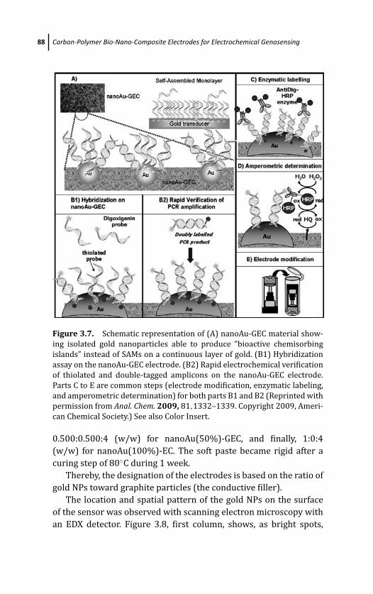
March 19, 2012 17:4 PSP Book - 9in x 6in 03-Ozsoz-c03
88 Carbon-Polymer Bio-Nano-Composite Electrodes for Electrochemical Genosensing
Figure 3.7. Schematic representation of (A) nanoAu-GEC material show-
ing isolated gold nanoparticles able to produce “bioactive chemisorbing
islands” instead of SAMs on a continuous layer of gold. (B1) Hybridization
assay on the nanoAu-GEC electrode. (B2) Rapid electrochemical verification
of thiolated and double-tagged amplicons on the nanoAu-GEC electrode.
Parts C to E are common steps (electrode modification, enzymatic labeling,
and amperometric determination) for both parts B1 and B2 (Reprinted with
permission from Anal. Chem. 2009, 81,1332–1339. Copyright 2009, Ameri-
can Chemical Society.) See also Color Insert.
0.500:0.500:4 (w/w) for nanoAu(50%)-GEC, and finally, 1:0:4
(w/w) for nanoAu(100%)-EC. The soft paste became rigid after a
curing step of 80◦C during 1 week.
Thereby, the designation of the electrodes is based on the ratio of
gold NPs toward graphite particles (the conductive filler).
The location and spatial pattern of the gold NPs on the surface
of the sensor was observed with scanning electron microscopy with
an EDX detector. Figure 3.8, first column, shows, as bright spots,
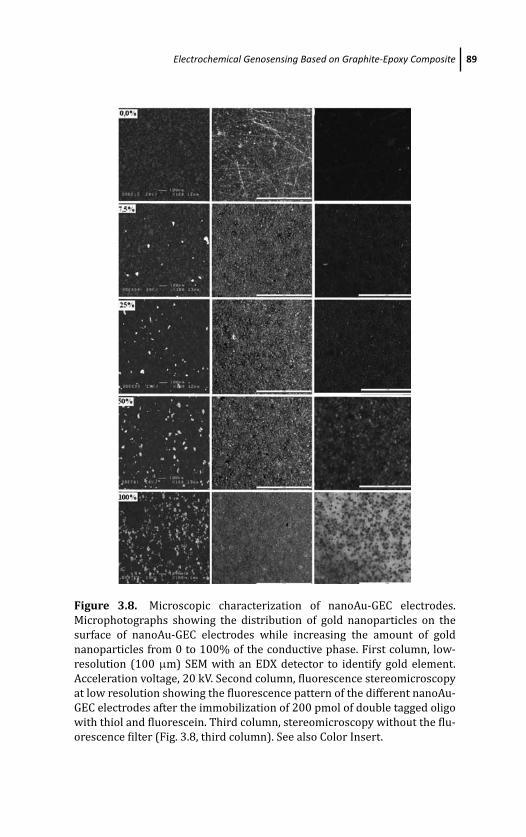
March 19, 2012 17:4 PSP Book - 9in x 6in 03-Ozsoz-c03
Electrochemical Genosensing Based on Graphite-Epoxy Composite 89
Figure 3.8. Microscopic characterization of nanoAu-GEC electrodes.
Microphotographs showing the distribution of gold nanoparticles on the
surface of nanoAu-GEC electrodes while increasing the amount of gold
nanoparticles from 0 to 100% of the conductive phase. First column, low-
resolution (100 μm) SEM with an EDX detector to identify gold element.
Acceleration voltage, 20 kV. Second column, fluorescence stereomicroscopy
at low resolution showing the fluorescence pattern of the different nanoAu-
GEC electrodes after the immobilization of 200 pmol of double tagged oligo
with thiol and fluorescein. Third column, stereomicroscopy without the flu-
orescence filter (Fig. 3.8, third column). See also Color Insert.
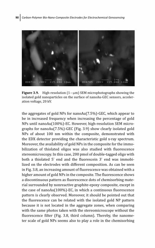
March 19, 2012 17:4 PSP Book - 9in x 6in 03-Ozsoz-c03
90 Carbon-Polymer Bio-Nano-Composite Electrodes for Electrochemical Genosensing
Figure 3.9. High-resolution (1−μm) SEM microphotographs showing the
isolated gold nanoparticles on the surface of nanoAu-GEC sensors, acceler-
ation voltage, 20 kV.
the aggregates of gold NPs for nanoAu(7.5%)-GEC, which appear to
be in increased frequency when increasing the percentage of gold
NPs until nanoAu(100%)-EC. However, high-resolution SEM micro-
graphs for nanoAu(7.5%)-GEC (Fig. 3.9) show clearly isolated gold
NPs of about 100 nm within the composite, demonstrated with
the EDX detector providing the characteristic gold x-ray spectrum.
Moreover, the availability of gold NPs in the composite for the immo-
bilization of thiolated oligos was also studied with fluorescence
stereomicroscopy. In this case, 200 pmol of double-tagged oligo with
both a thiolated 5′ end and the fluorescein 3′ end was immobi-
lized on the electrodes with different composition. As can be seen
in Fig. 3.8, an increasing amount of fluorescence was obtained with a
higher amount of gold NPs in the composite. The fluorescence shows
a discontinuous pattern as fluorescence dots of chemisorbing mate-
rial surrounded by nonreactive graphite-epoxy composite, except in
the case of nanoAu(100%)-EC, in which a continuous fluorescence
pattern is clearly observed. Moreover, it should be pointed out that
the fluorescence can be related with the isolated gold NP pattern
because it is not located in the aggregate zones, when comparing
with the same photos taken with the stereomicroscope without the
fluorescence filter (Fig. 3.8, third column). Thereby, the nanome-
ter scale of gold NPs seems also to play a role in the chemisorbing
March 19, 2012 17:4 PSP Book - 9in x 6in 03-Ozsoz-c03
Electrochemical Genosensing Based on Graphite-Epoxy Composite 91
ability of the gold nanocomposite material, especially in nanoAu
(7.5%)-GEC, since the fluorescence pattern is related to the isolated
gold NPs instead of the gold aggregates when increasing the amount
of goldNPs from 7.5 to 100%.
From the electrochemical evaluation of the electrodes, it can be
concluded that gold is more available for the electrochemical oxi-
dation in the nanoAu(7.5%)-GEC electrode and is present mostly as
NPs, instead of aggregates, showing the characteristic anodic peak
current near +1.1 V (vs. Ag/AgCl) [100]. The voltammetry for a vari-
ety of redox molecules at DNA-modified electrodes can provide addi-
tional qualitative information about the system’s organization on
the surface. The voltammetric reversibility of highly charged redox
ions is markedly influenced by the attractive/repulsive interactions
with the polyanionic DNA layer that the ions must penetrate to
reach the electrode surface, in the case of highly packed DNA mono-
layers [101]. The voltammetry for the ferrocyanide (3−/4−) redox
markers at the DNA-modified nanoAu-GEC is slightly affected by the
electrostatic interactions with the polyanionic layer, in contrast to
previous reported results for SAMs of DNA in continuous gold elec-
trodes [101], confirming the laxity of the DNA layer created on the
nanoAu(7.5%)-GEC electrode. These data suggest an architecture
that is made up of a disperse layer of oligonucleotide immobilized on
the isolated gold NPs and confirms the microscopic pattern achieved
by SEM and fluorescence microscopy [99].
Instead of SAMs on continuous layers of gold, isolated gold NPs
are able to produce “bioactive chemisorbing islands” for the immobi-
lization of thiolated biomolecules, avoiding stringent conditions for
surface coverage as well as the use of auxiliary reagents such as lat-
eral spacer thiols. Less compact layers are thus achieved favoring the
biological reaction on biosensing devices. Hybridization efficiency is
expected to be higher on the edging of the gold NPs surrounded by
nonreactive graphite-epoxy composite.
Briefly, the procedure consists of the following steps, as schemat-
ically outlined in Fig. 3.7: (i) thiolated probe immobilization by
chemisorption (Fig. 3.7A); (ii) hybridization with the complemen-
tary probe modified with either biotin or digoxigenin (Fig. 3.7B1);
(iii) enzyme labeling of the DNA duplex using streptavidin-HRP
or anti-DIG-HRP (Fig. 3.7C); and (iv) amperometric determination
March 19, 2012 17:4 PSP Book - 9in x 6in 03-Ozsoz-c03
92 Carbon-Polymer Bio-Nano-Composite Electrodes for Electrochemical Genosensing
based on the enzyme activity by adding H2O2 and using hydro-
quinone as a mediator (Fig. 3.7D).
The chemisorbing ability of gold NPs in the nano-AuGEC was
demonstrated with an excellent LOD (9 fmol/60 pM of ssDNA) in
hybridization studies. Regarding other electrochemical transducers
previously reported, such as an avidin graphite-epoxy biocompos-
ite (Av-GEB) or protein A graphite-epoxy biocomposite (ProtA-GEB)
[23], the main advantages of the inorganic nanoAu-GEC electrode
compared to the biocomposite is the lack of loss of activity and that
the latter requires the temperature to be kept at 4◦C due to the bio-
logical nature of the modifier, the protein avidin.
Moreover, and for the first time, a double-tagging PCR strat-
egy was performed with a thiolated primer for the detection of
Salmonella sp. The rapid electrochemical verification of the ampli-
con coming from the pathogenic genome of Salmonella performed
by PCR with a set of two labeled primers was demonstrated to be
an easy way for the thiolation of the PCR product. The thiolated end
allowed the immobilization of the amplicon on the nano-AuGEC elec-
trode in an easy way.
The procedure consists briefly of the following steps, as schemat-
ically outlined in Fig. 3.7: (i) DNA amplification and double-labeling
of Salmonella IS200 insertion sequence; (ii) immobilization of
the doubly labeled amplicon in which the SH end of the dsDNA
amplicon was immobilized on the nanoAu-GEC nanocomposites
by chemisorption (Fig. 3.7B2); (iii) enzymatic labeling using as
enzyme label the antibody anti-DIG-HRP capable of bonding the
other labeled extreme of the dsDNA amplicon (Fig. 3.7C); and (iv)
amperometric determination (Fig. 3.7D). With this strategy, as low
as 200 fmol can be easily detected, with an electrochemical signal of
almost 3 μA. This double tagging PCR strategy opens new routes not
only for immobilization purposes, but also act as an easy strategy for
labeling with gold or quantum dots during PCR.
The nanoAu-GEC material shows interesting properties for elec-
trochemical genosensing in hybridization experiments and very
promising features for electrochemical biosensing of a wide range of
biomolecules, such as dsDNA, PCR products, affinity proteins, anti-
bodies, or enzymes.
March 19, 2012 17:4 PSP Book - 9in x 6in 03-Ozsoz-c03
Final Remarks 93
3.5 Final Remarks
GEC-based platforms are useful and versatile transducer materials
for electrochemical DNA genosensing.
DNA can be attached directly onto a GEC surface by simple
adsorption (the simplest immobilization method and the easiest to
automate), avoiding the use of procedures based on previous activa-
tion/modification of the surface transducer and subsequent immo-
bilization, which are tedious, expensive, and time-consuming. This
procedure implies multisite attachment. Although DNA has been
widely attached onto carbonaceous materials, the underlying mech-
anism of adsorption has not been fully clarified. Adsorption is a
complex interplay between the chemical properties, structure, and
porosity of the substrate surface with the molecule being adsorbed.
DNA is a structurally polymorphic macromolecule which, depending
on nucleotide sequence and environmental conditions, can adopt a
variety of conformations. As a highly negatively charged molecule,
dsDNA is considered a hydrophilic molecule.
While dsDNA only partially shows its hydrophobic domain
through its major and minor grooves or through those sites where
dsDNA is open and exposing DNA bases, ssDNA has the hydrophobic
bases freely available for their interactions with hydrophobic sur-
faces.
These structural and chemical differences between ssDNA and
dsDNA are reflected in different adsorption patterns for both the
molecules.
The greater size and the more rigid shape of dsDNA with respect
to ssDNA are other parameters affecting their adsorption. Besides
the DNA molecule and the solid support, the solvent (normally
water), in particular the ionic strength, pH, and the nature of the
solutes, plays an important role in the adsorption process, mainly
in the stabilization of the adsorbed molecule on the substrate.
The hybridization event can be detected both with label-free or
enzymatic labeling procedures.
The single-point attachment of DNA can be achieved by the
immobilization of biotinylated DNA on Av-GEB platform. In this case,
a one-step immobilization/hybridization procedure is achieved. The
capability of surface regeneration of the biocomposite electrodes
March 19, 2012 17:4 PSP Book - 9in x 6in 03-Ozsoz-c03
94 Carbon-Polymer Bio-Nano-Composite Electrodes for Electrochemical Genosensing
allows repeated analyses with the same electrode as the Av-GEB
platform can be considered not only the transducer but also the
reservoir for the avidin.
The same immobilization strategy based on avidin/biotin link-
age can be achieved on magnetic beads. After their efficient mod-
ification, the magnetic beads can be easily captured on an m-GEC
transducer for the electrochemical determination of the hybridiza-
tion event.
The sensibility conferred by the m-GEC electrode in connection
with the use of magnetic beads and enzymatic labeling results in a
rapid, cheap, robust, and environment-friendly device which allows
the detection of pathogenic species on food, environmental, and clin-
ical samples.
The single-point attachment of DNA can also be achieved by
chemisorption of thiolated DNA on nanoAu-GEC platform. The
capability of surface regeneration of the nanocomposite electrodes
allows repeated analyses with the same electrode.
GEC materials present a low non-specific adsorption either for
DNA probes or enzyme labels. They do not require blocking steps to
minimize the non-specific adsorption on the free sites of the trans-
ducer.
Although the non-specific adsorption issues are controlled on
GEC, stringent conditions can be achieved when using avidin/biotin
linkage than when DNA is simply adsorbed, allowing rigorous con-
ditions for hybridization over longer times.
DNA biosensors based on GEC meet the demands of genetic
analysis, especially in food, biotechnology, and pharmaceutical
industries, while also generating new possibilities for the develop-
ment of DNA biosensors that are sensitive, robust, low cost, and eas-
ily produced.
For all the aforementioned reasons, it is possible to conclude that
GEC-based materials are very suitable platforms for DNA analysis.
References
1. D. Baltimore, Our genome unveiled, Nature, 409, 814–816 (2001).
2. D. D. L. Bowtell, Options available—from start to finish—for obtaining
expression data by microarray, Nature Gen. Suppl., 21, 25–32 (1999).
March 19, 2012 17:4 PSP Book - 9in x 6in 03-Ozsoz-c03
References 95
3. F. S. Collins, Microarrays and macroconsequences, Nature Gen. Suppl.,21, 2 (1999).
4. E. S. Lander, Array of hope, Nature Gen. Suppl., 21, 3–4 (1999).
5. G. H. W. Sanders and A. Manz, Chip-based microsystems for genomic
and proteomic analysis, Trends Anal. Chem., 19, 364–378 (2000).
6. B. S. Ferguson, S. F. Buchsbaum, J. S. Swensen, K. Hsieh, X. Lou, and H. T.
Soh, Analytical Chemistry, doi: 10.1021/ac900923e (2009).
7. R. Wirtz, C. P.. Walti, P. A. Tosch, M. Pepper, A. G. Davies, W. A. Ger-
mishuizen, A. P. J. Middelberg, Langmuir, 20, 1527–1530 (2004).
8. J. Wang, X. Cai, C. Jonsson, and M. Balakrishnan, Adsorptive stripping
potentiometry of DNA at electrochemically pretreated carbon paste
electrodes, Electroanalysis, 8, 20–24 (1996).
9. A. M. Oliveira Brett, S. H. P. Serrano, I. Gutz, M. A. La-Scalea, and M.
L. Cruz, Voltammetric behavior of nitroimidazoles at a DNA-biosensor,
Electroanalysis, 9, 1132–1137 (1997).
10. K. Hashimoto, K. Ito, and Y. Ishimori, Novel DNA sensor for electro-
chemical gene detection, Anal. Chim. Acta., 286, 219–224 (1994).
11. I. Moser, T. Schalkhammer, F. Pittner, and G. Urban, Surface techniques
for an electrochemical DNA biosensor, Biosens. Bioelectron., 12, 729–
737 (1997).
12. D. W. Pang and H. D. Abruna, Micromethod for the investigation of the
interactions between DNA and redox-active molecules, Anal. Chem., 70,
3162–3169 (1998).
13. P. M. Armistead and H. H. Thorp, Modification of indium tin oxide elec-
trodes with nucleic acids: detection of attomole quantities of immobi-
lized DNA by electrocatalysis, Anal. Chem., 72, 3764–3770 (2000).
14. F. Jelen, B. Yosypchuk, A.. Kourilova, L. Novotny, and E. Palecek, Label-
free determination of picogram quantities of DNA by stripping voltam-
metry with solid copper amalgam mercury in the presence of copper,
Anal. Chem., 74, 4788–4793 (2002).
15. M. Fojta and E. Palecek, Supercoiled DNA modified mercury electrode:
a highly sensitive tool for the detection of DNA damage, Anal. Chim.Acta., 342, 1–12 (1997).
16. M. I. Pividori, A. Merkoci, and S. Alegret, Electrochemical genosensor
design: immobilization of oligonucleotides onto transducer surfaces
and detection methods, Biosen. Bioelectron., 15, 291–303 (2000).
17. F. R. R. Teles and L. P. Fonseca, Applications of polymers for biomole-
cule immobilization in electrochemical biosensors, Materials Scienceand Engineering C., 28, 1530–1543 (2008).
March 19, 2012 17:4 PSP Book - 9in x 6in 03-Ozsoz-c03
96 Carbon-Polymer Bio-Nano-Composite Electrodes for Electrochemical Genosensing
18. S. Alegret, Rigid carbon–polymer biocomposites for electrochemical
sensing. A review, Analyst, 121, 1751–1758 1996.
19. J. Wang, Carbon-nanotube based electrochemical biosensors: A review,
Electroanalysis, 17, 7–14 (2005).
20. Rajesh, T. Ahuja, and D. Kumar, Recent progress in the development
of nano-structured conducting polymers/nanocomposites for sensor
applications, Sensors and Actuators B, 136, 275–286 (2009).
21. J. M. Pingarron, P. Yanez-Sedeno, and A. Gonzalez-Cortes, Gold
nanoparticle-based electrochemical biosensors, Electrochimica Acta,
53, 5848–5866 (2008).
22. J. F. Cassidy, A. P. Doherty, and J. G. Vos, in D. Diamond (ed.), Principlesof Chemical and Biological Sensors John Wiley & Sons, Toronto, (1998).
23. E. Zacco, M. I. Pividori, and S. Alegret, Electrochemical biosensing
based on universal affinity biocomposite platforms, Biosens. Bioelec-tron., 21, 1291–1301 (2006).
24. E. Southern, K. Mir, and M. Shchepinov, Molecular interactions on
microarrays, Nature Genetics Supp., 21, 5–9 (1999).
25. M. I. Pividori and S. Alegret, Electrochemical genosensing based on
rigid carbon composites. A review., Anal. Lett., 38, 2541–2565 (2005).
26. K. M. Millan, A. L. Spurmanis, and S. K. Mikkelsen, Covalent immobiliza-
tion of DNA onto glassy carbon electrodes, Electroanalysis, 4, 929–932
(1992).
27. K. M. Millan and S. K. Mikkelsen, Sequence-selective biosensor for DNA
based on electroactive hybridization indicators, Anal. Chem., 65, 2317–
2323 (1993).
28. K. M. Millan, A. Saraullo, and S. K. Mikkelsen, Voltammetric DNA biosen-
sor for cystic fibrosis based on a modified carbon paste electrode, Anal.Chem., 66, 2943–2948 (1994).
29. X. Sun, P. He, S. Liu, L. Ye, and Y. Fang, Immobilization of single
stranded deoxyribonucleic acid on gold electrode with self-assembled
aminoethanethiol monolayer for DNA electrochemical sensor applica-
tions, Talanta, 47, 487–495 (1998).
30. J. Wang and Y. H. Lin, Functionalized carbon nanotubes and nanofibers
for biosensing applications, Trends in Analytical Chemistry, 27, 619–
626 (2008).
31. R. G. Nuzzo and D. L. Allara, Adsorption of bifunctional organic disul-
fides on gold surfaces, J. Am. Chem. Soc., 105, 4481–4483 (1983).
32. T. M. Herne and M. J. Tarlov, Characterization of DNA probes immobi-
lized on gold surfaces, J. Am. Chem. Soc., 119, 8916–8920 (1997).
March 19, 2012 17:4 PSP Book - 9in x 6in 03-Ozsoz-c03
References 97
33. M. T. Carter, M. Rodriguez, and A. L. Bard, Voltammetric studies of the
interaction of metal chelates with DNA. 2. Tris-chelated complexes of
cobalt(III) and iron(II) with 1,10-phenanthroline and 2,2%-bipyridine,
J. Am. Chem. Soc., 111, 8901–8911 (1989).
34. A. Erdem, K. Kerman, B. Meric, and M. Ozsoz, Methylene blue as a novel
electrochemical hybridization indicator, Electroanalysis, 13, 219–223
(2001).
35. M. I. Pividori, A. Merkoci, and Alegret, Classical dot-blot format imple-
mented as an amperometric hybridisation genosensor, Biosens. Bio-electron., 16, 1133–1142 (2001).
36. M. I. Pividori and S. Alegret, Graphite-epoxy platforms for electrochem-
ical genosensing, Anal. Lett., 36, 1669–1695 (2003).
37. L. Alfonta, A. K. Singh, and I. Willner, Liposomes labelled with biotin
and horseradish peroxidase: a probe for the enhanced amplification of
antigen—antibody or oligonucleotide—DNA sensing processes by the
precipitation of an insoluble product on electrodes, Anal. Chem., 73,
91–102 (2001).
38. E. Palecek, R. Kizek, L. Havran, S. Billova, and M. Fotja, Electrochemi-
cal enzyme-linked immunoassay in a DNA hybridization sensor, Anal.Chim. Acta., 469, 73–83 (2002).
39. M. B. Gonzalez-Garcıa, C. Fernandez-Sanchez, and A. Costa-Garcıa,
Biosens. Bioelectron., 15, 315–321 (2000).
40. M. Dequaire, C. Degrand, and B. Limoges, Anal. Chem. 72, 5521–5528
(2000).
41. J. Wang, R. Polsky, and D. Xu, Langmuir, 17, 5739–5741 (2001).
42. J. Wang, D. Xu, A.-N. Kawde, and R. Polsky, Metal nanoparticle-based
electrochemical stripping potentiometric detection of DNA hybridiza-
tion, Anal. Chem., 73, 5576–5581 (2001).
43. E. Paleeek, Oscillographic polarography of nucleic acids and their
buildingblocks, Naturwiss, 45, 186–187 (1958).
44. E. Palecek, Oscillographic polarography of highly polymerized deoxyri-
bonucleic acid, Nature., 188, 656–657 (1960).
45. G. R. Ruschau, R. E. Newnham, J. Runt, and E. Smith, 0–3 ceramic
polymer composite chemical sensors, Sens. Actuators, 20, 269–275
(1989).
46. S. Alegret, A. Merkoci, M. I. Pividori, and M. Del Valle, in Encyclopedia ofSensors (C. A. Grimes, E. C. Dickey, M. V. Pishko eds.), American Scien-
tific Publishers, 3, 23–44 (2005).
March 19, 2012 17:4 PSP Book - 9in x 6in 03-Ozsoz-c03
98 Carbon-Polymer Bio-Nano-Composite Electrodes for Electrochemical Genosensing
47. M. R. Bockstaller, R. A. Mickievitch, and E. L. Thomas, Block copolymer
nanocomposites: perspectives for tailored functional materials, Adv.Mater., 17, 1331–1349 (2005).
48. F. Cespedes, E. Fabregas, and S. Alegret, New materials for electro-
chemical sensing I. Rigid conducting composites, Trends Anal. Chem.,
15, 296–304 (1996).
49. F. Cespedes and S. Alegret, New materials for electrochemical sensing
II. Rigid carbon–polymer biocomposites, Trends Anal. Chem., 19, 276–
285 (2000).
50. D. D. Borole, U. R. Kapadi, P. P. Mahulikar, and D. G. Hundiwale, Conduct-
ing polymers: an emerging field of biosensors, Des. Monomers Polym.,
9, 1–11 (2006).
51. M. Gerard, A. Chaubey, and B. D. Malhotra, Application of conducting
polymers to biosensors, Biosens. Bioelectron., 17, 345–359 (2002).
52. D. Y. Godovski, E. A. Koltypin, A. V. Volkov, and M. A. Moskvina, Sen-
sor properties of filled polymer composites, Analyst, 118, 997–999
(1993).
53. P. K. Sudeep and T. Emrick, Polymer-nanoparticle composites: prepar-
ative methods and electronically active materials, Polymer Reviews, 47,
155–163 (2007).
54. A. B. Lowe, B. S. Sumerlin, M. S. Donovan, and C. L. McCormick,
Facile preparation of transition metal nanoparticles stabilized by well-
defined (co)polymers synthesized via aqueous reversible addition-
fragmentation chain transfer polymerization, J. Am. Chem. Soc., 124,
11562–11563 (2002).
55. K. J. Watson, J. Zhu, J., S. T. Nguyen, and C. A. Mirkin, Hybrid nanoparti-
cles with block copolymer shell structures, J. Am. Chem. Soc. 121, 462–
463 (1999).
56. R. Hong, R. Fischer, R. Verma, C. M. Goodman, T. Emrick, and V. M.
Rotello, Control of protein structure and function through surface
recognition by tailored nanoparticle scaffolds, J. Am. Chem. Soc., 126,
739–743 (2004).
57. M. Streat, D. J. Malik, and B. Saha, Adsorption and ion-exchange prop-
erties of engineered activated carbons and carbonaceous materials, in
Ion Exchange and Solvent Extraction, chap 1 (A. K. SenGupta, Y. Marcus,
J. A. Marinsky eds.), Dekker, New York, (2004).
58. L. V. Radushkevich and V. M. Lukyanovich, O strukture
ugleroda, obrazujucegosja pri termiceskom razlozenii okisi ugleroda
na zeleznom kontakte, Zurn Fisic Chim., 26, 88–95 (1952).
March 19, 2012 17:4 PSP Book - 9in x 6in 03-Ozsoz-c03
References 99
59. H. W. Kroto, J. R. Heath, S. C. O’Brien, R. F. Curl, and R. E. Smalley, C60:
Buckminsterfullerene, Nature, 318, 162–163 (1985).
60. S. Iijima and T. Ichihashi Single-shell carbon nanotubes of 1-nm diam-
eter, Nature, 363, 603–605 (1993).
61. D. S. Bethune, C. H. Kiang, M. S. De Vries, G. Gorman, R. Savoy, J. Vazquez,
and R. Beyers, Cobalt catalysed growth of carbon nanotubes with sin-
gle atomic- layer walls, Nature, 363, 605–607 (1993).
62. Y. Ando, X. Zhao, T. Sugai, and M. Kumar, Growing carbon nanotubes,
Materials Today, oct, 22–29 (2004).
63. S. Niyogi, E. Bekyarova, M. E. Itkis, J. L. McWilliams, M. A. Hamon, and R.
C. Haddon, Solution Properties of Graphite and Graphene, J. Am. Chem.Soc., 128, 7720–7721 (2006).
64. X. Chu and K. Kinoshita, Surface modification of carbons for enhanced
electrochemical activity, Mater. Sci. Eng. B, 49, 53–60 (1997).
65. F. Regisser, M. A. Lavoie, G. Y. Champagne, and D. Belanger, Randomly
oriented graphite electrode 1. Effect of electrochemical pretreatment
on the electrochemical behavior and chemical composition of the elec-
trode, J. Electroanal. Chem., 415, 47–54 (1996).
66. A. Hirsch, Functionalization of single-walled carbon nanotubes, Angew.Chem. Int. Ed., 41, 1853–1859 (2002).
67. S. Banerjee, T. Hemraj-Benny, and S. S. Wong, Covalent surface chem-
istry of single-walled carbon nanotubes, Advanced Materials, 17, 17–
29 (2005).
68. H. Cai, X. N. Cao, Y. Jiang, P. G. He, and Y. Z. Fang, Carbon nanotube-
enhanced electrochemical DNA biosensor for DNA hybridization
detection, Anal. Bioanal. Chem., 375, 287–293 (2003).
69. J. Li, H. T. Ng, A. Cassell, W. Fan, H. Chen, Q. Ye, J. Koehne, J. Han, and M.
Meyyappan, Carbon nanotube nanoelectrode array for ultrasensitive
DNA detection, Nano. Lett., 3, 597–602 (2003).
70. R. N. Adams, Carbon paste electrodes, Anal. Chem., 30, 1576 (1958).
71. S. Liebana, A. Lermo, S. Campoy, J. Barbe, S. Alegret, and M. I. Pividori,
Magneto immunoseparation of pathogenic bacteria and electrochemi-
cal magneto genosensing of the double-tagged amplicon, Anal. Chem.,
81, 5812–5820 (2009).
72. S. Liebana, A. Lermo, S. Campoy, M. P. Cortes, S. Alegret, and M.
I. Pividori, Rapid detection of Salmonella in milk by electrochem-
ical magneto immunosensing, Biosens. Bioelectron., 25, 510–513
(2009).
March 19, 2012 17:4 PSP Book - 9in x 6in 03-Ozsoz-c03
100 Carbon-Polymer Bio-Nano-Composite Electrodes for Electrochemical Genosensing
73. E. Zacco, M. I. Pividori, X. Llopis, M. del Valle, and S. Alegret, Renew-
able Protein A modified graphite-epoxy composite for electrochemical
immunosensing, J. Immun. Methods, 286, 35–46 (2004).
74. E. Williams, M. I. Pividori, A. Merkoci, R. J. Forster, and S. Alegret,
Rapid electrochemical genosensor assay using a streptavidin carbon-
polymer biocomposite electrode, Biosens. Bioelectron., 19, 165–175
(2003).
75. A. Lermo, E. Zacco, J. Barak, M. Delwiche, S. Campoy, J. Barbe, S.
Alegret, and M. I. Pividori, Towards Q-PCR of pathogenic bacteria
with improved electrochemical double-tagged genosensing detection,
Biosens. Bioelectron., 23, 1805–1811 (2008).
76. S. R. Rasmussen, M. R. Larsen, and S. E. Rasmussen, Covalent immobi-
lization of DNA onto polystyrene microwells: the molecules are only
bound at the 5’ end, Anal. Biochem., 198, 138–142 (1991).
77. D. W. Pang, M. Zhang, Z. L. Wang, Y. P. Qi, J. K. Cheng, and Z. Y. Liu, Mod-
ification of glassy carbon and gold electrodes with DNA, J. Electroanal.Chem., 403, 183–188 (1996).
78. M. I. Pividori and S. Alegret, DNA adsorption on carbonaceous materi-
als, in Immobilization of DNA on Chips I, Topics in Current Chemistry (C.
Wittman, ed.), Springer Verlag, Berlın, 260, 1–36 (2005).
79. M. I. Pividori, A. Merkoci, J. Barbe, and S. Alegret, PCR-genosensor
rapid test for detecting Salmonella, Electroanalysis, 15, 1815–1823
(2003).
80. M. I. Pividori, A. Merkoci, and S. Alegret, Graphite–epoxy composites
as new transducing material for electrochemical genosensing, Biosens.Bioelectron., 19, 473–484 (2003).
81. C. N. Campbell, D. Gai, N. Cristler, C. Banditrat, and A. Heller, Enzyme
amplified amperometric sandwich test for RNA and DNA, Anal. Chem.,
74, 158–162 (2002).
82. T. Lumley-Woodyear, C. N. Campbell, E. Freeman, A. Freeman, G. Geor-
giou, and A. Heller, Rapid amperometric verification of PCR amplifica-
tion of DNA, Anal. Chem., 71, 535–538 (1999).
83. A. Erdem, M. I. Pividori, M. del Valle, and S. Alegret, Rigid carbon
composites: a new transducing material for label-free electrochemical
genosensing, J. Electroanal. Chem., 567, 29–37 (2004).
84. M. L. Jones and G. P. Kurzban, Noncooperativity of biotin binding to
tetrameric streptavidin, Biochemistry, 34, 11750–11756 (1995).
85. Y. Katayama, T. Ito, and K. Hiramatsu, A new class of genetic ele-
ment, staphylococcus cassette chromosome mec, encodes methicillin
March 19, 2012 17:4 PSP Book - 9in x 6in 03-Ozsoz-c03
References 101
resistance in Staphylococcus aureus, Antimicrob. Agents Chemother.,
44, 1549–1555 (2000).
86. B. I. Haukanes and C. Kvam, Application of magnetic beads in bioassays,
Biotechnology, 11, 60–63 (1993).
87. E. Zacco, M. I. Pividori, S. Alegret, R. Galve, and M.-P. Marco, Electro-
chemical magneto-immunosensing strategy for the detection of pesti-
cides residues, Anal. Chem., 78, 1780–1788 (2006).
88. A. G. Gehring, J. D. Brewster, P. L. Irwin, S. I. Tu, and L. J. Van Houten,
1-Naphthyl phosphate as an enzymatic substrate for enzyme-linked
immunomagnetic electrochemistry, J. Electroanal. Chem., 469, 27–33
(1999).
89. M. Dequaire, C. Degrand, and B. Limoges, An immunomagnetic electro-
chemical sensor based on a perfluorosulfonate-coated screen-printed
electrode for the determination of 2,4-dichlorophenoxyacetic acid,
Anal. Chem., 71, 2571–2577 (1999).
90. E. Palecek and F. Jelen, Electrochemistry of nucleic acids and
development of DNA sensors, Crit. Rev. Anal. Chem., 32, 261–270
(2002).
91. J. Wang, A.-N. Kawde, A. Erdem, and M. Salazar, Magnetic bead-based
label-free electrochemical detection of DNA hybridization, Analyst,
126, 2020–2024 (2001).
92. J. Wang and A.-N. Kawde, Magnetic-field stimulated DNA oxidation,
Electrochem. Commun., 4, 349–352 (2002).
93. J. Wang, G.-U. Flechsig, A. Erdem, O. Korbut, and P. Grundler, Label
free DNA hybridization based on coupling of a heated carbon paste
electrode with magnetic separations, Electroanalysis, 16, 928–931
(2004).
94. E. Palecek, S. Billova, L. Havran, R. Kizek, A. Miculkova, and F. Jelen,
DNA hybridization at microbeads with cathodic stripping voltammet-
ric detection, Talanta, 56, 919–930 (2002).
95. J. Wang, D. Xu, and R. Polsky, Magnetically-induced solid-state electro-
chemical detection of DNA hybridization, J. Am. Chem. Soc., 124, 4208–
4209 (2002).
96. A. Erdem, M. I. Pividori, A. Lermo, A. Bonanni, A., M. del Valle, and S.
Alegret, Sens. Actuators B, 114, 591–598 (2006).
97. A. Lermo, S. Campoy, J. Barbe, S. Hernandez, S. Alegret, and M. I. Pivi-
dori, In situ DNA amplification with magnetic primers for the electro-
chemical detection of food pathogens, Biosens. Bioelectron., 22, 2010–
2017 (2007).
March 19, 2012 17:4 PSP Book - 9in x 6in 03-Ozsoz-c03
102 Carbon-Polymer Bio-Nano-Composite Electrodes for Electrochemical Genosensing
98. S. Liebana, A. Lermo, S. Campoy, J. Barbe, S. Alegret, and M. I. Pividori,
Magneto immunoseparation of pathogenic bacteria and electrochemi-
cal magneto genosensing of the double-tagged amplicon, Anal. Chem.,
81, 5812–5820 (2009).
99. P. R. B. Oliveira Marques, A. Lermo, S. Campoy, H. Yamanaka, J. Barbe,
S. Alegret, and M. I. Pividori, Double-tagging polymerase chain reac-
tion with a thiolated primer and electrochemical genosensing based
on gold nanocomposite sensor for food safety, Anal. Chem., 81, 1332–
1339 (2009).
100. H. O. Finklea, S. Avery, M. Lynch, and T. Furtsch, Blocking oriented
monolayers of alkyl mercaptans on gold electrodes, Langmuir, 3, 409–
413 (1987).
101. A. R. Steel, T. M. Herne, and M. J. Tarlov, Electrochemical quantification
of DNA immobilized on gold, Anal. Chem., 70, 4670–4677 (1998).
March 14, 2012 20:1 PSP Book - 9in x 6in 04-Ozsoz-c04
Chapter 4
Gold Nanoparticle-BasedElectrochemical DNA Biosensors
Marıa Pedrero, Paloma Yanez-Sedeno, and Jose M. PingarronDepartamento de Quımica Analıtica, Facultad de Ciencias Quımicas,Universidad Complutense de Madrid, Avenida Complutense s/n, E-28040 Madrid, [email protected]
Nowadays, gold nanoparticles play a key role in the construction of
a new generation of biosensors and, in particular, electrochemical
biosensors. This chapter is devoted to electrochemical DNA biosen-
sors coupled with the use of gold nanoparticles to improve both
oligonucleotide immobilization on electrode surfaces and signal
amplification for sensitive detection of hybridization events. Recent
advances in the development of these biosensors are covered,
stressing on the improvement of the analytical performance.
Configurations used for DNA immobilization and signal transduction
and amplification strategies are treated separately.
4.1 Introduction
The use of nanomaterials for the construction of efficient and
powerful biosensing devices constitutes nowadays one of the
research lines with more activity and effort in modern bioanalytical
Electrochemical DNA BiosensorsEdited by Mehmet OzsozCopyright c© 2012 Pan Stanford Publishing Pte. Ltd.ISBN 978-981-4241-77-9 (Hardcover), 978-981-4303-98-9 (eBook)www.panstanford.com

March 14, 2012 20:1 PSP Book - 9in x 6in 04-Ozsoz-c04
104 Gold Nanoparticle-Based Electrochemical DNA Biosensors
chemistry. The extremely promising prospects of nanomaterials-
based biodevices accrue from the unique properties of nanomateri-
als, making possible advanced applications where limits of detection
at zeptomolar concentrations and ultra-sensitive multiplexed detec-
tion can be achieved [1]. Different types of nanomaterials can be
employed to design and construct these biosensing devices: carbon
nanotubes, nanowires including metal, silicon, conducting polymer,
and metal oxide nanowires, nanocantilivers, quantum dots, and
nanoparticles, including metal, metal oxide, semiconductor, and
magnetic nanoparticles. A nice overview on the use of nanomaterials
for the construction of biosensors can be found in the monography
edited by Kumar [1].
In this context, the preparation of nanostructured electrode
surfaces constitutes also a priority research line with high activity
in the field of electroanalytical chemistry [2]. This electrode
modification strategy combines, on the one hand, advances in
sensor technology, offering a wide range of approaches using or
not biological systems, as well as several (bio)assay-transduction
symbiotic strategies, and, on the other hand, the applications of
nanotechnology in its wider sense as the products, processes, and
systems operating at nanometric scale. The use of nanostructured
electrode surfaces produces significant advantages from the electro-
analytical point of view. In general, they improve the kinetics of the
electron-transfer reactions, exhibit electrocatalytic ability toward
many electrochemical processes of biological significance allowing
the detection potentials to be lowered, and show an anti-fouling
capability for the products of many electrochemical reactions. These
characteristics improve basic analytical properties such as the
sensitivity and selectivity of the methods and the repeatability of the
measurements.
Although most of the nanomaterials mentioned above can be
employed for this purpose, gold nanoparticles play a key role in the
construction of a new generation of biosensors and, in particular,
of electrochemical biosensors. The ability of gold nanoparticles to
provide a stable surface for the immobilization of biomolecules
retaining their biological activity is a major advantage for the
preparation of biosensors. Moreover, gold nanoparticles allow
direct electron transfer between redox proteins and bulk electrode

March 14, 2012 20:1 PSP Book - 9in x 6in 04-Ozsoz-c04
Introduction 105
materials to be performed thus enabling electrochemical sensing
with no need for electron-transfer mediators. Properties of gold
nanoparticles, such as their high surface-to-volume ratio, high
surface energy, the ability to decrease the distance between proteins
and metal particles, and their performance as electron-conducting
pathways between the prosthetic groups and the electrode surface,
have been claimed as reasons to improve electron transfer between
redox proteins and electrodes [3]. Also, gold nanoparticles have
shown to constitute useful interfaces for the electrocatalysis of redox
processes of molecules such as H2O2, O2, or NADH involved in the
biochemical reactions with analytical significance [4].
This chapter is devoted to electrochemical DNA biosensors
coupled with the use of gold nanoparticles to improve both
oligonucleotide immobilization on electrode surfaces and signal
amplification for sensitive detection of hybridization events. Elec-
trochemical genosensors have demonstrated in recent years to
constitute reliable alternatives for applications directed to gene
analysis, detection of genetic disorders, tissue matching and
forensics, due to their high sensitivity, small dimensions, low cost,
and compatibility with microfabrication technology. Besides tra-
ditional electrochemical transduction of DNA hybridization events
involving electroactive indicators/intercalators or enzyme tags,
the use of nanoparticles, especially of gold nanoparticles, offers
elegant pathways for interfacing such events with electrochemical
signal transduction and for amplification of the resulting electrical
response [5].
Gold nanoparticles can be employed for improving the immo-
bilization of DNA on electrode surfaces and thus for increasing
the hybridization capacity of the modified surface [6]. The use of
gold nanoparticles supporting films constructed by self-assembling
of 16-nm diameter colloidal gold onto a cystamine-modified gold
electrode resulted in surface densities of oligonucleotides as high as
4 × 10¹⁴ molecules cm−2, allowing a detection limit of 500 pM to be
achieved.
The other fundamental advantage of gold nanoparticles-based
electrochemical DNA biosensors is the development of amplification
routes for the DNA sensing events. According to Willner et al. [7], the
concept of the amplified detection of DNA using gold nanoparticles
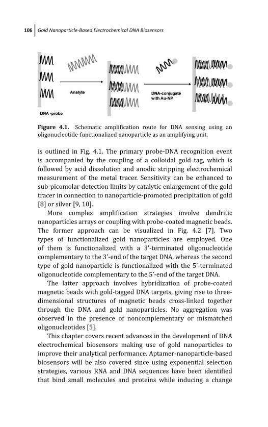
March 14, 2012 20:1 PSP Book - 9in x 6in 04-Ozsoz-c04
106 Gold Nanoparticle-Based Electrochemical DNA Biosensors
Figure 4.1. Schematic amplification route for DNA sensing using an
oligonucleotide-functionalized nanoparticle as an amplifying unit.
is outlined in Fig. 4.1. The primary probe-DNA recognition event
is accompanied by the coupling of a colloidal gold tag, which is
followed by acid dissolution and anodic stripping electrochemical
measurement of the metal tracer. Sensitivity can be enhanced to
sub-picomolar detection limits by catalytic enlargement of the gold
tracer in connection to nanoparticle-promoted precipitation of gold
[8] or silver [9, 10].
More complex amplification strategies involve dendritic
nanoparticles arrays or coupling with probe-coated magnetic beads.
The former approach can be visualized in Fig. 4.2 [7]. Two
types of functionalized gold nanoparticles are employed. One
of them is functionalized with a 3’-terminated oligonucleotide
complementary to the 3’-end of the target DNA, whereas the second
type of gold nanoparticle is functionalized with the 5’-terminated
oligonucleotide complementary to the 5’-end of the target DNA.
The latter approach involves hybridization of probe-coated
magnetic beads with gold-tagged DNA targets, giving rise to three-
dimensional structures of magnetic beads cross-linked together
through the DNA and gold nanoparticles. No aggregation was
observed in the presence of noncomplementary or mismatched
oligonucleotides [5].
This chapter covers recent advances in the development of DNA
electrochemical biosensors making use of gold nanoparticles to
improve their analytical performance. Aptamer-nanoparticle-based
biosensors will be also covered since using exponential selection
strategies, various RNA and DNA sequences have been identified
that bind small molecules and proteins while inducing a change
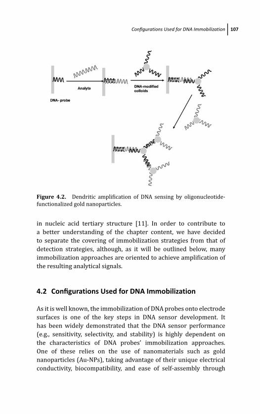
March 14, 2012 20:1 PSP Book - 9in x 6in 04-Ozsoz-c04
Configurations Used for DNA Immobilization 107
Figure 4.2. Dendritic amplification of DNA sensing by oligonucleotide-
functionalized gold nanoparticles.
in nucleic acid tertiary structure [11]. In order to contribute to
a better understanding of the chapter content, we have decided
to separate the covering of immobilization strategies from that of
detection strategies, although, as it will be outlined below, many
immobilization approaches are oriented to achieve amplification of
the resulting analytical signals.
4.2 Configurations Used for DNA Immobilization
As it is well known, the immobilization of DNA probes onto electrode
surfaces is one of the key steps in DNA sensor development. It
has been widely demonstrated that the DNA sensor performance
(e.g., sensitivity, selectivity, and stability) is highly dependent on
the characteristics of DNA probes’ immobilization approaches.
One of these relies on the use of nanomaterials such as gold
nanoparticles (Au-NPs), taking advantage of their unique electrical
conductivity, biocompatibility, and ease of self-assembly through
March 14, 2012 20:1 PSP Book - 9in x 6in 04-Ozsoz-c04
108 Gold Nanoparticle-Based Electrochemical DNA Biosensors
a thiol group. Large specific surface Au-NPs-modified electrodes
can enhance the amount of DNA immobilized onto the electrode
leading to an improvement of the biosensor performance. Many of
the examples reported in the literature imply a previous chemical
preparation of Au-NPs, with a subsequent modification of the
electrode surface through physical adsorption or chemical linking.
Nanomaterial-based platforms suitable to construct biosensors
are fabricated in this way. Alternatively, direct electrochemical
deposition of Au-NPs onto the electrode surface constitutes a rapid,
clean, and versatile mode to create nanomaterial platforms in situ for
the construction of DNA biosensors. The next sections revise some
illustrative examples of several designs employed to prepare such
platforms.
4.2.1 Au-Thiol Binding
Gold electrode substrates have attracted special attention for
the preparation of electrochemical DNA biosensors since DNA
can be strongly bound at the surface of gold through Au–thiol
binding. Thiolated DNA can be monolayered on gold in a self-
assembly manner, which provides stable and structurally well-
defined electrochemical interfaces. However, one major drawback
of the gold electrode is attributed to the cleaning step; in order
to obtain reproducible results, the gold electrode needs to be
mechanically polished and then electrochemically etched in acid
solutions. This time-consuming process determines a quality of
electrochemical DNA biosensors.
Various recent interesting configurations of genosensors take
advantage of the Au–thiol binding strategy with gold nanoparticles,
for example, gold nanoparticles were electrodeposited on screen-
printed electrodes which were subsequently modified with a self-
assembled monolayer of thiol-capped single-stranded DNA (capture
probe) (Fig. 4.3). This immobilization strategy was employed to
construct a genosensor for the detection of the rfbE gene, which is
specific to E. coli O157 [12].
A similar immobilization methodology has been used to develop
a DNA-sensing platform for Helicobacter pylori [13]. Rigid conduct-
ing gold nanocomposites have been also modified with this strategy.
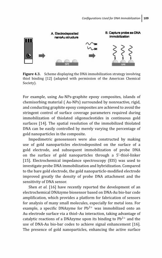
March 14, 2012 20:1 PSP Book - 9in x 6in 04-Ozsoz-c04
Configurations Used for DNA Immobilization 109
Figure 4.3. Scheme displaying the DNA immobilization strategy involving
thiol binding [12] (adapted with permission of the American Chemical
Society).
For example, using Au-NPs-graphite epoxy composites, islands of
chemisorbing material ( Au-NPs) surrounded by nonreactive, rigid,
and conducting graphite epoxy composites are achieved to avoid the
stringent control of surface coverage parameters required during
immobilization of thiolated oligonucleotides in continuous gold
surfaces [14]. The spatial resolution of the immobilized thiolated
DNA can be easily controlled by merely varying the percentage of
gold nanoparticles in the composite.
Impedimetric genosensors were also constructed by making
use of gold nanoparticles electrodeposited on the surface of a
gold electrode, and subsequent immobilization of probe DNA
on the surface of gold nanoparticles through a 5’-thiol-linker
[15]. Electrochemical impedance spectroscopy (EIS) was used to
investigate probe DNA immobilization and hybridization. Compared
to the bare gold electrode, the gold nanoparticle-modified electrode
improved greatly the density of probe DNA attachment and the
sensitivity of DNA sensor.
Shen et al. [16] have recently reported the development of an
electrochemical DNAzyme biosensor based on DNA-Au bio-bar code
amplification, which provides a platform for fabrication of sensors
for analysis of many small molecules, especially for metal ions. For
example, a specific DNAzyme for Pb2+ was immobilized onto an
Au electrode surface via a thiol–Au interaction, taking advantage of
catalytic reactions of a DNAzyme upon its binding to Pb2+ and the
use of DNA-Au bio-bar codes to achieve signal enhancement [16].
The presence of gold nanoparticles, enhancing the active surface
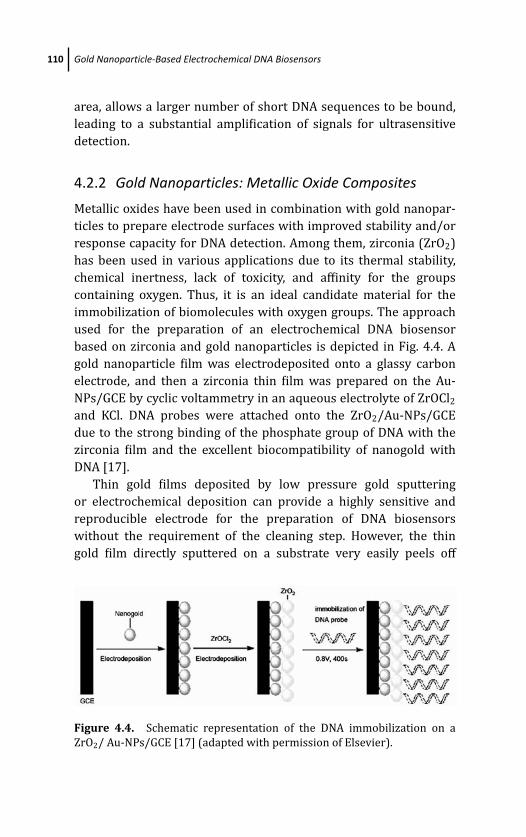
March 14, 2012 20:1 PSP Book - 9in x 6in 04-Ozsoz-c04
110 Gold Nanoparticle-Based Electrochemical DNA Biosensors
area, allows a larger number of short DNA sequences to be bound,
leading to a substantial amplification of signals for ultrasensitive
detection.
4.2.2 Gold Nanoparticles: Metallic Oxide Composites
Metallic oxides have been used in combination with gold nanopar-
ticles to prepare electrode surfaces with improved stability and/or
response capacity for DNA detection. Among them, zirconia (ZrO2)
has been used in various applications due to its thermal stability,
chemical inertness, lack of toxicity, and affinity for the groups
containing oxygen. Thus, it is an ideal candidate material for the
immobilization of biomolecules with oxygen groups. The approach
used for the preparation of an electrochemical DNA biosensor
based on zirconia and gold nanoparticles is depicted in Fig. 4.4. A
gold nanoparticle film was electrodeposited onto a glassy carbon
electrode, and then a zirconia thin film was prepared on the Au-
NPs/GCE by cyclic voltammetry in an aqueous electrolyte of ZrOCl2
and KCl. DNA probes were attached onto the ZrO2/Au-NPs/GCE
due to the strong binding of the phosphate group of DNA with the
zirconia film and the excellent biocompatibility of nanogold with
DNA [17].
Thin gold films deposited by low pressure gold sputtering
or electrochemical deposition can provide a highly sensitive and
reproducible electrode for the preparation of DNA biosensors
without the requirement of the cleaning step. However, the thin
gold film directly sputtered on a substrate very easily peels off
Figure 4.4. Schematic representation of the DNA immobilization on a
ZrO2/ Au-NPs/GCE [17] (adapted with permission of Elsevier).
March 14, 2012 20:1 PSP Book - 9in x 6in 04-Ozsoz-c04
Configurations Used for DNA Immobilization 111
during immobilization or electrochemical measurement, giving less
reliability. To avoid this problem, DNA biosensors using a thin
gold film sputtered on capacitive anodic nanoporous niobium
oxide were proposed [18]. The nanoporous niobium oxide offers
a good adhesion as well as an enhancement of redox signals by
accumulation of charges in between the gold film and the niobium
oxide. The mechanism of enhancing the signal by the thin gold film
on nanoporous niobium oxide is in part attributed to capacitive
niobium oxide and is in part ascribed to the bridged thin gold
film.
4.2.3 Carbon Nanotube–Gold Nanoparticle Hybrids
Carbon nanotubes (CNTs) are widely recognized as an ideal support
for fabricating electrochemical sensors with a high sensitivity
and selectivity [19]. Due to the ability of carbon nanotubes
to promote electron-transfer reactions, and the high catalytic
activity and biocompatibility of gold nanoparticles, the developed
genosensors showed excellent reproducibility and stability under
the DNA hybridization conditions [20]. A novel DNA biosensor
was constructed by layer-by-layer (LBL) covalent assembly of
gold nanoparticles and multiwalled carbon nanotubes (MWCNTs).
Cysteamine molecules acted as a glue to connect activated MWCNTs
and Au-NPs into a three-dimensional hybrid network on a gold
electrode. Then, NH2-ssDNA was immobilized on multilayer films via
amino link at the 5’-end.
4.2.4 Polymer–Gold Nanoparticle Hybrids
Because electrochemical polymerization allows the control of film
thickness, permeation, and charge-transport characteristics by
adjusting the electrochemical parameters, this methodology has
demonstrated to be a promising approach to immobilize DNA
probes. Among other electronconducting polymers, polyaniline
(PANI) has attracted a special attention in the field of conducting
macromolecules. Due to its homogeneity, unique redox properties,
high electrical conductivity and strong adherence to electrode sur-
face, PANI has been extensively applied to develop electrochemical
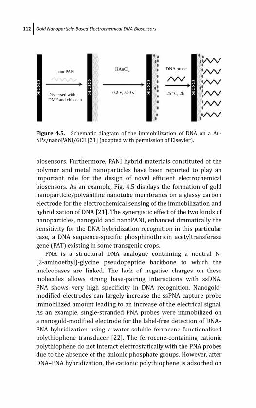
March 14, 2012 20:1 PSP Book - 9in x 6in 04-Ozsoz-c04
112 Gold Nanoparticle-Based Electrochemical DNA Biosensors
nanoPAN
Dispersed withDMF and chitosan
– 0.2 V, 500 s 25 °C, 2h
DNA probeHAuCl4
Figure 4.5. Schematic diagram of the immobilization of DNA on a Au-
NPs/nanoPANI/GCE [21] (adapted with permission of Elsevier).
biosensors. Furthermore, PANI hybrid materials constituted of the
polymer and metal nanoparticles have been reported to play an
important role for the design of novel efficient electrochemical
biosensors. As an example, Fig. 4.5 displays the formation of gold
nanoparticle/polyaniline nanotube membranes on a glassy carbon
electrode for the electrochemical sensing of the immobilization and
hybridization of DNA [21]. The synergistic effect of the two kinds of
nanoparticles, nanogold and nanoPANI, enhanced dramatically the
sensitivity for the DNA hybridization recognition in this particular
case, a DNA sequence-specific phosphinothricin acetyltransferase
gene (PAT) existing in some transgenic crops.
PNA is a structural DNA analogue containing a neutral N-
(2-aminoethyl)-glycine pseudopeptide backbone to which the
nucleobases are linked. The lack of negative charges on these
molecules allows strong base-pairing interactions with ssDNA.
PNA shows very high specificity in DNA recognition. Nanogold-
modified electrodes can largely increase the ssPNA capture probe
immobilized amount leading to an increase of the electrical signal.
As an example, single-stranded PNA probes were immobilized on
a nanogold-modified electrode for the label-free detection of DNA–
PNA hybridization using a water-soluble ferrocene-functionalized
polythiophene transducer [22]. The ferrocene-containing cationic
polythiophene do not interact electrostatically with the PNA probes
due to the absence of the anionic phosphate groups. However, after
DNA–PNA hybridization, the cationic polythiophene is adsorbed on

March 14, 2012 20:1 PSP Book - 9in x 6in 04-Ozsoz-c04
Configurations Used for DNA Immobilization 113
the DNA backbone, giving a clear hybridization detection signal by
differential pulse voltammetry.
Electrochemical DNA biosensors were also prepared using
carbon nanotube-polymer hybrids in combination with gold
nanoparticles. Composite materials based on integration of CNTs
and polymers have gained growing interest because they possess
the properties of each component with a synergistic effect. In a
recent report [23], p-aminobenzoic acid (PABA), which contains
electron-rich N atom and high electron density of carbonyl group,
was electrodeposited by cyclic voltammetry on the surface of a
multiwalled carbon nanotube-modified glassy carbon electrode.
Gold nanoparticles were subsequently electrodeposited onto the
surface of the PABA/MWNTs composite film, and the probe DNA was
immobilized on the surface of Au-NPs through an Au–S bond.
4.2.5 Avidin–Biotin Affinity Reactions
Electrochemical detection of bioaffinity interactions with a gold
nanoparticles sensing platform was accomplished by using
thrombin–thrombin binding aptamer couple as a model [24]. The
aptamer was immobilized on a screen-printed electrode modified
with gold nanoparticles by avidin–biotin technology. The cathodic
peak area resulting from the reduction of previously formed gold
oxide was found to be proportional to the thrombin quantity
specifically adsorbed onto the modified electrode surface.
Dendritic polymers (dendrimers) belong to a new class of
synthetic macromolecules possessing a regularly branched tree-
like structure. A great attention has been paid to the potential
applications of polyamidoamine (PAMAM) dendrimers for the
development of biosensors, because of the dendrimer high geo-
metric symmetry, chemical stability, controllable size, and surface
functionality. Dendrimer–Au-NPs nanocomposites have been shown
to combine the physical and chemical properties of Au-NPs with
the surface reactivity of dendrimers. A recent report describes an
electrochemical approach for sequence-specific DNA detection using
PAMAM and gold nanoparticles [25]. The biosensor design consisted
of a gold electrode modified with 3-mercaptopropionic acid, which
was reacted with an amino-terminated polyamidoamine (PAMAM,
March 14, 2012 20:1 PSP Book - 9in x 6in 04-Ozsoz-c04
114 Gold Nanoparticle-Based Electrochemical DNA Biosensors
G 4.0-NH2) to obtain a thin film. Single-stranded 3’-biotin end-
labeled oligonucleotide was immobilized onto the film to obtain a
stable recognition layer through biotin–avidin combination to detect
complementary target.
4.3 Signal Transduction and Amplification Strategies
Recent literature dealing with integration of Au-NPs with DNA
detection systems shows that different strategies can be employed to
achieve improved analytical performance of the resulting genosen-
sors. As mentioned above, using Au-NPs-modified electrodes, the
amount of DNA immobilized onto the electrode can be considerably
enhanced. The efficient immobilization of DNA onto the transducer
paves the way for the design of effective signal transduction
approaches of the hybridization event. Furthermore, Au-NPs have
been employed as amplification components which when combined
with electrochemical techniques have given rise to the design of
selective and highly sensitive DNA sensors [26]. Castaneda et al. [27]
and Guo et al. [26, 28] have recently reviewed the achievements of
the electrochemical sensing of DNA using Au-NPs.
In a rather general approach, and in order to systematize the
content of this section, we have considered separately the detection
strategies that take advantage of the design of sensing platforms
integrating Au-NPs, but in which the detection methodology itself
does not involve Au-NPs as an element to obtain the signal trans-
duction, and those involving direct participation of Au-NPs in the
generation of the electroanalytical signals. In the next subsections,
some illustrative examples of each of these methodologies will be
commented, and tables summarizing other recent works using the
different detection strategies will be given.
4.3.1 Detection Strategies Not Involving DirectParticipation of Au-NPs in the Generationof the Electrochemical Signal
The immobilization methods commented in Sec. 4.2 can be
coupled with signal transduction methodologies involving different
March 14, 2012 20:1 PSP Book - 9in x 6in 04-Ozsoz-c04
Signal Transduction and Amplification Strategies 115
strategies such as the detection of redox markers, the detection
based on enzymatic labels, the detection based on electrochemical
labels intercalated within ds-DNA, and the use of Au-NPs as carriers
for other nanoparticles or other electrochemical labels which are
responsible for the generation of the analytical signals.
4.3.1.1 Direct detection of redox markers
Figure 4.3 showed an example involving DNA immobilization
through thiol binding onto gold nanoparticles electrodeposited on
screen-printed electrodes. This sensor architecture allowed the
development of an electrochemical sensor for the detection of E.coli O157 based on competition between the target gene (com-
plementary to the capture probe DNA) and reporter DNA-tagged,
hexaammineruthenium (III) chloride–encapsulated liposomes. The
current signal of the released liposomal [Ru(NH3)6]3+ was mea-
sured using square wave voltammetry (SWV), yielding a sigmoidal-
shaped dose-response curve whose linear portion was over the
range from 1 to 106 fmol. This liposomal competitive assay provided
an amplification route for the detection of the rfbE gene (specific to
E. coli O157) at ultratrace levels, with a detection limit of 0.75 amol
[12].
Another interesting example of direct detection of redox markers
is a ferrocene catalyzed aptamer-based thrombin sensor [29].
Figure 4.6 displays the sensor architecture and functioning. A
thrombin binding aptamer was covalently immobilized onto three-
dimensional Au-NP–doped conducting polymer nanorod electrodes
(Au-NPs/3D-CPNEs). Ferrocene was attached with anti-thrombin
through streptavidin-biotin interactions and it electrochemically
catalyzed the oxidation of ascorbic acid. Since thrombin was
sandwiched between thrombin aptamer and anti-thrombin anti-
body attached with ferrocene, the catalytic current response was
proportional to the thrombin concentration. The aptamer sensor
showed a dynamic range from 5 to 2000 ng L−1 with a detection
limit of 5 ng L−1 (0.14 pM) and it was applied to the determination
of spiked concentrations of thrombin in real human serum samples.
Another interesting approach involves the use of quantum dot
tracers. For example, Huang et al. [30] have described a DNA
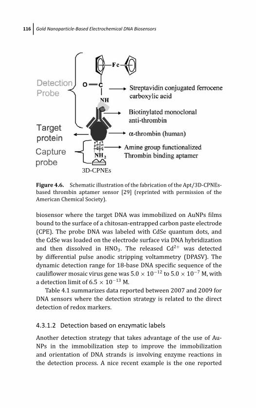
March 14, 2012 20:1 PSP Book - 9in x 6in 04-Ozsoz-c04
116 Gold Nanoparticle-Based Electrochemical DNA Biosensors
3D-CPNEs
Figure 4.6. Schematic illustration of the fabrication of the Apt/3D-CPNEs-
based thrombin aptamer sensor [29] (reprinted with permission of the
American Chemical Society).
biosensor where the target DNA was immobilized on AuNPs films
bound to the surface of a chitosan-entrapped carbon paste electrode
(CPE). The probe DNA was labeled with CdSe quantum dots, and
the CdSe was loaded on the electrode surface via DNA hybridization
and then dissolved in HNO3. The released Cd2+ was detected
by differential pulse anodic stripping voltammetry (DPASV). The
dynamic detection range for 18-base DNA specific sequence of the
cauliflower mosaic virus gene was 5.0 × 10⁻¹² to 5.0 × 10⁻⁷ M, with
a detection limit of 6.5 × 10⁻¹³ M.
Table 4.1 summarizes data reported between 2007 and 2009 for
DNA sensors where the detection strategy is related to the direct
detection of redox markers.
4.3.1.2 Detection based on enzymatic labels
Another detection strategy that takes advantage of the use of Au-
NPs in the immobilization step to improve the immobilization
and orientation of DNA strands is involving enzyme reactions in
the detection process. A nice recent example is the one reported
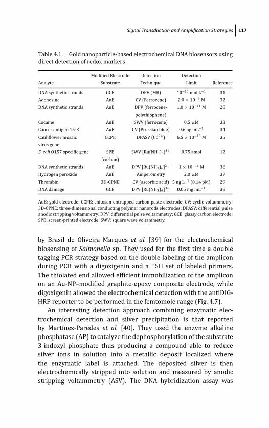
March 14, 2012 20:1 PSP Book - 9in x 6in 04-Ozsoz-c04
Signal Transduction and Amplification Strategies 117
Table 4.1. Gold nanoparticle-based electrochemical DNA biosensors using
direct detection of redox markers
Modified Electrode Detection Detection
Analyte Substrate Technique Limit Reference
DNA synthetic strands GCE DPV (MB) 10−10 mol L−1 31
Adenosine AuE CV (Ferrocene) 2.0 × 10⁻⁸ M 32
DNA synthetic strands AuE DPV (ferrocene- 1.0 × 10⁻¹¹ M 28
polythiophene)
Cocaine AuE SWV (ferrocene) 0.5 μM 33
Cancer antigen 15-3 AuE CV (Prussian blue) 0.6 ng mL−1 34
Cauliflower mosaic CCPE DPASV (Cd2+) 6.5 × 10⁻¹³ M 35
virus gene
E. coli O157 specific gene SPE SWV [Ru(NH3)6]3+ 0.75 amol 12
(carbon)
DNA synthetic strands AuE DPV [Ru(NH3)6]3+ 1 × 10⁻¹¹ M 36
Hydrogen peroxide AuE Amperometry 2.0 μM 37
Thrombin 3D-CPNE CV (ascorbic acid) 5 ng L−1 (0.14 pM) 29
DNA damage GCE DPV [Ru(NH3)6]3+ 0.05 mg mL−1 38
AuE: gold electrode; CCPE: chitosan-entrapped carbon paste electrode; CV: cyclic voltammetry;
3D-CPNE: three-dimensional conducting polymer nanorods electrodes; DPASV: differential pulse
anodic stripping voltammetry; DPV: differential pulse voltammetry; GCE: glassy carbon electrode;
SPE: screen-printed electrode; SWV: square wave voltammetry.
by Brasil de Oliveira Marques et al. [39] for the electrochemical
biosensing of Salmonella sp. They used for the first time a double
tagging PCR strategy based on the double labeling of the amplicon
during PCR with a digoxigenin and a –SH set of labeled primers.
The thiolated end allowed efficient immobilization of the amplicon
on an Au-NP–modified graphite-epoxy composite electrode, while
digoxigenin allowed the electrochemical detection with the antiDIG-
HRP reporter to be performed in the femtomole range (Fig. 4.7).
An interesting detection approach combining enzymatic elec-
trochemical detection and silver precipitation is that reported
by Martınez-Paredes et al. [40]. They used the enzyme alkaline
phosphatase (AP) to catalyze the dephosphorylation of the substrate
3-indoxyl phosphate thus producing a compound able to reduce
silver ions in solution into a metallic deposit localized where
the enzymatic label is attached. The deposited silver is then
electrochemically stripped into solution and measured by anodic
stripping voltammetry (ASV). The DNA hybridization assay was
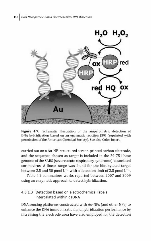
March 14, 2012 20:1 PSP Book - 9in x 6in 04-Ozsoz-c04
118 Gold Nanoparticle-Based Electrochemical DNA Biosensors
red
Figure 4.7. Schematic illustration of the amperometric detection of
DNA hybridization based on an enzymatic reaction [39] (reprinted with
permission of the American Chemical Society). See also Color Insert.
carried out on a Au-NP–structured screen-printed carbon electrode,
and the sequence chosen as target is included in the 29 751-base
genome of the SARS (severe acute respiratory syndrome)-associated
coronavirus. A linear range was found for the biotinylated target
between 2.5 and 50 pmol L−1 with a detection limit of 2.5 pmol L−1.
Table 4.2 summarizes works reported between 2007 and 2009
using an enzymatic approach to detect hybridization.
4.3.1.3 Detection based on electrochemical labelsintercalated within dsDNA
DNA sensing platforms constructed with Au-NPs (and other NPs) to
enhance the DNA immobilization and hybridization performance by
increasing the electrode area have also employed for the detection
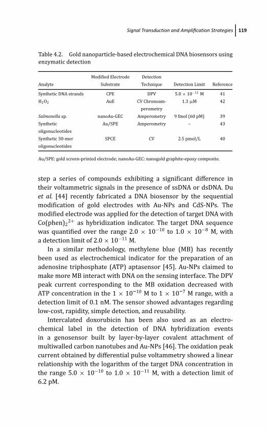
March 14, 2012 20:1 PSP Book - 9in x 6in 04-Ozsoz-c04
Signal Transduction and Amplification Strategies 119
Table 4.2. Gold nanoparticle-based electrochemical DNA biosensors using
enzymatic detection
Modified Electrode Detection
Analyte Substrate Technique Detection Limit Reference
Synthetic DNA strands CPE DPV 5.0 × 10⁻¹¹ M 41
H2O2 AuE CV Chronoam- 1.3 μM 42
perometry
Salmonella sp. nanoAu-GEC Amperometry 9 fmol (60 pM) 39
Synthetic Au/SPE Amperometry – 43
oligonucleotides
Synthetic 30-mer SPCE CV 2.5 pmol/L 40
oligonucleotides
Au/SPE: gold screen-printed electrode; nanoAu-GEC: nanogold graphite-epoxy composite.
step a series of compounds exhibiting a significant difference in
their voltammetric signals in the presence of ssDNA or dsDNA. Du
et al. [44] recently fabricated a DNA biosensor by the sequential
modification of gold electrodes with Au-NPs and CdS-NPs. The
modified electrode was applied for the detection of target DNA with
Co(phen)22+ as hybridization indicator. The target DNA sequence
was quantified over the range 2.0 × 10⁻¹⁰ to 1.0 × 10⁻⁸ M, with
a detection limit of 2.0 × 10⁻¹¹ M.
In a similar methodology, methylene blue (MB) has recently
been used as electrochemical indicator for the preparation of an
adenosine triphosphate (ATP) aptasensor [45]. Au-NPs claimed to
make more MB interact with DNA on the sensing interface. The DPV
peak current corresponding to the MB oxidation decreased with
ATP concentration in the 1 × 10⁻¹⁰ M to 1 × 10⁻⁷ M range, with a
detection limit of 0.1 nM. The sensor showed advantages regarding
low-cost, rapidity, simple detection, and reusability.
Intercalated doxorubicin has been also used as an electro-
chemical label in the detection of DNA hybridization events
in a genosensor built by layer-by-layer covalent attachment of
multiwalled carbon nanotubes and Au-NPs [46]. The oxidation peak
current obtained by differential pulse voltammetry showed a linear
relationship with the logarithm of the target DNA concentration in
the range 5.0 × 10⁻¹⁰ to 1.0 × 10⁻¹¹ M, with a detection limit of
6.2 pM.
March 14, 2012 20:1 PSP Book - 9in x 6in 04-Ozsoz-c04
120 Gold Nanoparticle-Based Electrochemical DNA Biosensors
Also, intercalated adriamycin has been used as hybridization
label in a genosensor built by modifying a glassy carbon electrode
(GCE) with multiwalled carbon nanotubes with carboxyl groups and
Au-NPs [23]. Differential pulse voltammetry (DPV) was utilized to
monitor the DNA hybridization event. Under the optimal conditions,
the increase of reduction peak current of adriamycin was linear
with the logarithm of the concentration of the complementary
oligonucleotides from 1.0 × 10⁻¹² to 5.0 × 10⁻⁹ M with a detection
limit of 3.5 × 10⁻¹³ M.
An interesting and relatively new water soluble intercalating
compound, pentaamin ruthenium [3-(2-phenanthren-9-yl-vinyl)-
pyridine] complex [Ru(NH3)5L] prepared in situ, has been also
used to detect the hybridization event. The metal provides with
a redox centre that can be used as the electrochemical indicator,
while gold nanoparticles contribute to facilitate the electron transfer
between the redox indicator and the electrode surface by acting
as tiny conduction centres. Following this detection strategy,
complementary target sequences of H. pylori were detected over the
range 40 to 800 pmol with a detection limit of 25±2 pmol [13].
Table 4.3 summarizes data reported between 2007 and 2009
for electrochemical genosensors based on dsDNA-intercalated
electrochemical labels.
4.3.1.4 Detection involving the use of Au-NPs as carriers
Au-NPs can be used as nanocarriers for other NPs or other
electroactive species. As a result, the DNA detection is notably
enhanced compared to the use of single labels. However, this
strategy requires a careful work to avoid irreproducibility in the
biosensors’ response [27].
In this context, Ding et al. [50] have recently described a sensitive
assay for sequence specific DNA detection based on bio-bar code
techniques, and using electrochemical detection of Cd ions dissolved
from CdS-nanoparticles. Figure 4.8 shows a scheme of the method
used for the amplified sensing of target DNA. Sandwich-type DNA
complexes were fabricated with a thiol-functionalized capture DNA
sequence immobilized on an Au-NP–GCE and hybridized with one
end of target DNA. The other end of target DNA was recognized with
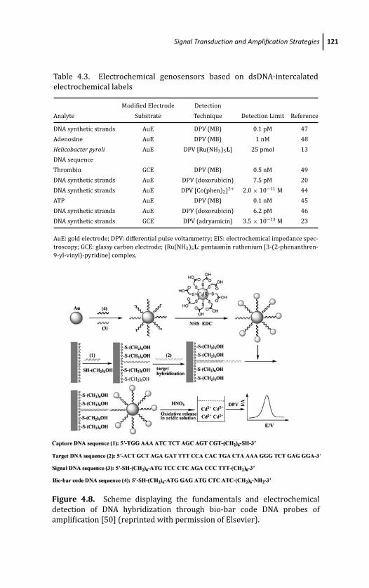
March 14, 2012 20:1 PSP Book - 9in x 6in 04-Ozsoz-c04
Signal Transduction and Amplification Strategies 121
Table 4.3. Electrochemical genosensors based on dsDNA-intercalated
electrochemical labels
Modified Electrode Detection
Analyte Substrate Technique Detection Limit Reference
DNA synthetic strands AuE DPV (MB) 0.1 pM 47
Adenosine AuE DPV (MB) 1 nM 48
Helicobacter pyroli AuE DPV [Ru(NH3)5L] 25 pmol 13
DNA sequence
Thrombin GCE DPV (MB) 0.5 nM 49
DNA synthetic strands AuE DPV (doxorubicin) 7.5 pM 20
DNA synthetic strands AuE DPV [Co(phen)2]2+ 2.0 × 10⁻¹¹ M 44
ATP AuE DPV (MB) 0.1 nM 45
DNA synthetic strands AuE DPV (doxorubicin) 6.2 pM 46
DNA synthetic strands GCE DPV (adryamicin) 3.5 × 10⁻¹³ M 23
AuE: gold electrode; DPV: differential pulse voltammetry; EIS: electrochemical impedance spec-
troscopy; GCE: glassy carbon electrode; (Ru(NH3)5L: pentaamin ruthenium [3-(2-phenanthren-
9-yl-vinyl)-pyridine] complex.
Figure 4.8. Scheme displaying the fundamentals and electrochemical
detection of DNA hybridization through bio-bar code DNA probes of
amplification [50] (reprinted with permission of Elsevier).
March 14, 2012 20:1 PSP Book - 9in x 6in 04-Ozsoz-c04
122 Gold Nanoparticle-Based Electrochemical DNA Biosensors
signal DNA labeled on the surface of Au-NPs. In order to amplify
the detection signals, the Au-NPs were also modified with CdS-NPs.
Since a single Au-NP could be loaded with hundreds of signal DNA
probe strands, a significant amplification for the detection of target
DNA was achieved. The hybridization events were monitored by
measuring the Cd ions dissolved from the hybrids using differential
pulse voltammetry (DPV). The peak current values increased with
the target DNA concentration in the range 1.0 × 10⁻¹⁴ to 1.0
× 10−13, and a detection limit of 4.2 × 10⁻¹⁵ M was achieved. Two-
base mismatched sequences showed weaker peak current and non-
complementary sequences gave no response at all.
Another recent approach [51] consisted of the construction
of a DNA sandwich electrochemical biosensor based on the use
of PbS-NPs attached to AuNPs/bio-bar code–modified magnetic
microbeads (MBs). The magnetic carriers containing PbS-NPs
labeled DNA probe were immersed in an electrochemical cell
containing 1.0 M HNO3 and the released Pb2+ was measured by
anodic stripping voltammetry (ASV) at a mercury film electrode
(MFE). The target DNA gave a linear response in the range from
2.0 × 10⁻¹⁴ M to 1.0 × 10⁻¹² M, with a detection limit of 5.0 ×10⁻¹⁵ M.
Similar detection strategies involve immobilization of DNA-
modified Au-NPs onto the working electrode surface through
hybridization, and the use of molecules binding to DNA as
electrochemical labels. As an example, Miao et al. [52] described a
sensing strategy for the detection of glutathione in fetal calf serum
based on the use of two Au electrodes and two complementary
oligonucleotides (Fig. 4.9). The surface of one AuE is modified
with one of the two oligonucleotides and then immersed in the
glutathione solution where, due to the ligand release effect, the
oligonucleotides are replaced by glutathione. When the second AuE
is immersed in the solution, the released oligonucleotide molecules
are immobilized onto this electrode surface. Then, Au-NPs modified
with the complementary oligonucleotide are added and immobilized
onto this electrode surface through hybridization. Large numbers of
[Ru(NH3)6]3+ are then localized onto the electrode surface via the
electrostatic interaction between the electrochemical species and
oligonucleotide molecules. Since the Au-NPs amplify the detection

March 14, 2012 20:1 PSP Book - 9in x 6in 04-Ozsoz-c04
Signal Transduction and Amplification Strategies 123
Figure 4.9. Schematic illustration of ultrasensitive detection of glu-
tathione based on the use of Au-NPs as carriers of electrochemical labels
[52] (reprinted with permission of Elsevier).
signal, glutathione could be detected in the range from 1 × 10⁻¹² to
1 × 10⁻¹⁰ M, with a detection limit of 4 × 10⁻¹³M.
Bio-bar code technique was also employed by Shen et al.[16] with an electrochemical DNAzyme biosensor. The DNAzyme
hybridizes to a specially designed complementary substrate strand
that has an overhang, which in turn hybridizes to the DNA-
Au bio-bar code (short oligonucleotides attached to 13-nm gold
nanoparticles). Upon binding of Pb2+ to the DNAzyme, the DNAzyme
March 14, 2012 20:1 PSP Book - 9in x 6in 04-Ozsoz-c04
124 Gold Nanoparticle-Based Electrochemical DNA Biosensors
catalyzes the hydrolytic cleavage of the substrate, resulting in
the removal of the substrate strand along with the DNA bio-
bar code and the bound [Ru(NH3)6]3+ from the Au electrode
surface. The release of Ru(NH3)3+6 results in lower electrochemical
signal of Ru(NH3)3+6 confined to the electrode surface. Because each
nanoparticle carries a large number of DNA strands that bind to the
signal transducer molecule Ru(NH3)3+6 , the use of DNA-Au bio-bar
codes enhances the detection sensitivity by 5 times, enabling the
detection of Pb2+ at a very low level (1 nM). The DPV signal response
of the DNAzyme sensor is negligible for other divalent metal ions,
indicating that the sensor is highly selective for Pb2+. Table 4.4
summarizes recent works found in the literature for genosensors
making use of Au-NPs as carriers for other NPs or other electroactive
species.
4.3.2 Detection Strategies Involving Direct Participationof Au-NPs in the Generation of theElectrochemical Signal
Other detection strategies involve direct participation of Au-
NPs in the generation of the electroanalytical signal used for
quantification of target DNA. These include the detection systems
based on Au-NPs dissolving, label-free electrochemical impedance
and conductimetric detection approaches, different methodologies
for signal enhancement by precipitation of silver or even gold onto
Au-NP–DNA conjugates and Au-NP enlargement strategies. Some
illustrative examples of these strategies are discussed below.
4.3.2.1 Detection based on Au-NPs’ acidic orelectrochemical dissolving
This detection procedure is based on the oxidative dissolution of
the Au-NPs bound to DNA into aqueous Au ions followed by their
electrochemical sensing. Chemical dissolution of the Au-NP tags has
been mainly carried out with a HBr/Br2 solution, this step being
followed by accumulation and stripping analysis of the resulting
Au(III) ions. Due to the high toxicity of the HBr/Br2 solution, other
oxidation methods have been also employed.
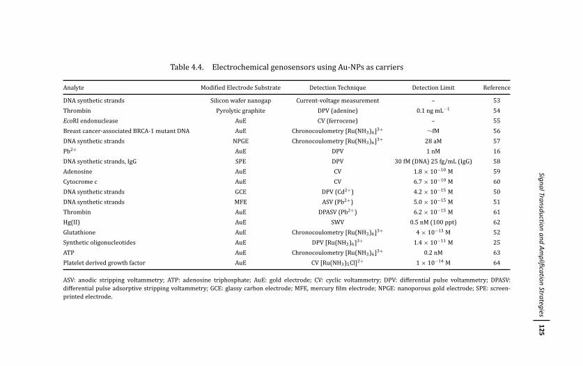
March
14,201220:1
PSPBook
-9inx
6in04-O
zsoz-c04
SignalTransductionand
Amplification
Strategies125
Table 4.4. Electrochemical genosensors using Au-NPs as carriers
Analyte Modified Electrode Substrate Detection Technique Detection Limit Reference
DNA synthetic strands Silicon wafer nanogap Current-voltage measurement – 53
Thrombin Pyrolytic graphite DPV (adenine) 0.1 ng mL−1 54
EcoRI endonuclease AuE CV (ferrocene) – 55
Breast cancer-associated BRCA-1 mutant DNA AuE Chronocoulometry [Ru(NH3)6]3+ ∼fM 56
DNA synthetic strands NPGE Chronocoulometry [Ru(NH3)6]3+ 28 aM 57
Pb2+ AuE DPV 1 nM 16
DNA synthetic strands, IgG SPE DPV 30 fM (DNA) 25 fg/mL (IgG) 58
Adenosine AuE CV 1.8 × 10⁻¹⁰ M 59
Cytocrome c AuE CV 6.7 × 10⁻¹⁰ M 60
DNA synthetic strands GCE DPV (Cd2+) 4.2 × 10⁻¹⁵ M 50
DNA synthetic strands MFE ASV (Pb2+) 5.0 × 10⁻¹⁵ M 51
Thrombin AuE DPASV (Pb2+) 6.2 × 10⁻¹⁵ M 61
Hg(II) AuE SWV 0.5 nM (100 ppt) 62
Glutathione AuE Chronocoulometry [Ru(NH3)6]3+ 4 × 10⁻¹³ M 52
Synthetic oligonucleotides AuE DPV [Ru(NH3)6]3+ 1.4 × 10⁻¹¹ M 25
ATP AuE Chronocoulometry [Ru(NH3)6]3+ 0.2 nM 63
Platelet derived growth factor AuE CV [Ru(NH3)5Cl]2+ 1 × 10⁻¹⁴ M 64
ASV: anodic stripping voltammetry; ATP: adenosine triphosphate; AuE: gold electrode; CV: cyclic voltammetry; DPV: differential pulse voltammetry; DPASV:
differential pulse adsorptive stripping voltammetry; GCE: glassy carbon electrode; MFE, mercury film electrode; NPGE: nanoporous gold electrode; SPE: screen-
printed electrode.
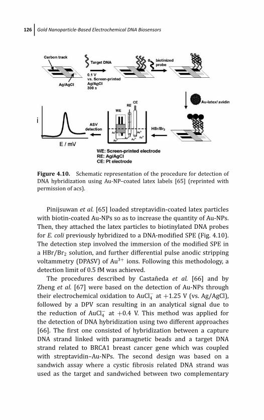
March 14, 2012 20:1 PSP Book - 9in x 6in 04-Ozsoz-c04
126 Gold Nanoparticle-Based Electrochemical DNA Biosensors
Figure 4.10. Schematic representation of the procedure for detection of
DNA hybridization using Au-NP–coated latex labels [65] (reprinted with
permission of acs).
Pinijsuwan et al. [65] loaded streptavidin-coated latex particles
with biotin-coated Au-NPs so as to increase the quantity of Au-NPs.
Then, they attached the latex particles to biotinylated DNA probes
for E. coli previously hybridized to a DNA-modified SPE (Fig. 4.10).
The detection step involved the immersion of the modified SPE in
a HBr/Br2 solution, and further differential pulse anodic stripping
voltammetry (DPASV) of Au3+ ions. Following this methodology, a
detection limit of 0.5 fM was achieved.
The procedures described by Castaneda et al. [66] and by
Zheng et al. [67] were based on the detection of Au-NPs through
their electrochemical oxidation to AuCl−4 at +1.25 V (vs. Ag/AgCl),
followed by a DPV scan resulting in an analytical signal due to
the reduction of AuCl−4 at +0.4 V. This method was applied for
the detection of DNA hybridization using two different approaches
[66]. The first one consisted of hybridization between a capture
DNA strand linked with paramagnetic beads and a target DNA
strand related to BRCA1 breast cancer gene which was coupled
with streptavidin–Au-NPs. The second design was based on a
sandwich assay where a cystic fibrosis related DNA strand was
used as the target and sandwiched between two complementary
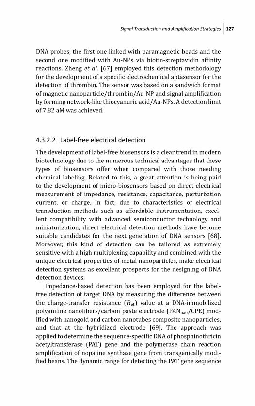
March 14, 2012 20:1 PSP Book - 9in x 6in 04-Ozsoz-c04
Signal Transduction and Amplification Strategies 127
DNA probes, the first one linked with paramagnetic beads and the
second one modified with Au-NPs via biotin-streptavidin affinity
reactions. Zheng et al. [67] employed this detection methodology
for the development of a specific electrochemical aptasensor for the
detection of thrombin. The sensor was based on a sandwich format
of magnetic nanoparticle/thrombin/Au-NP and signal amplification
by forming network-like thiocyanuric acid/Au-NPs. A detection limit
of 7.82 aM was achieved.
4.3.2.2 Label-free electrical detection
The development of label-free biosensors is a clear trend in modern
biotechnology due to the numerous technical advantages that these
types of biosensors offer when compared with those needing
chemical labeling. Related to this, a great attention is being paid
to the development of micro-biosensors based on direct electrical
measurement of impedance, resistance, capacitance, perturbation
current, or charge. In fact, due to characteristics of electrical
transduction methods such as affordable instrumentation, excel-
lent compatibility with advanced semiconductor technology and
miniaturization, direct electrical detection methods have become
suitable candidates for the next generation of DNA sensors [68].
Moreover, this kind of detection can be tailored as extremely
sensitive with a high multiplexing capability and combined with the
unique electrical properties of metal nanoparticles, make electrical
detection systems as excellent prospects for the designing of DNA
detection devices.
Impedance-based detection has been employed for the label-
free detection of target DNA by measuring the difference between
the charge-transfer resistance (Ret) value at a DNA-immobilized
polyaniline nanofibers/carbon paste electrode (PANnao/CPE) mod-
ified with nanogold and carbon nanotubes composite nanoparticles,
and that at the hybridized electrode [69]. The approach was
applied to determine the sequence-specific DNA of phosphinothricin
acetyltransferase (PAT) gene and the polymerase chain reaction
amplification of nopaline synthase gene from transgenically modi-
fied beans. The dynamic range for detecting the PAT gene sequence

March 14, 2012 20:1 PSP Book - 9in x 6in 04-Ozsoz-c04
128 Gold Nanoparticle-Based Electrochemical DNA Biosensors
was from 1.0 × 10⁻¹² to 1.0 × 10⁻⁶ M, with a detection limit of 5.6 ×10⁻¹³ M.
Furthermore, as commented in Sec. 4,2.1, impedimetric genosen-
sors were also constructed by making use of gold nanoparticles
electrodeposited on the surface of a gold electrode, and subsequent
immobilization of probe DNA on the surface of gold nanoparticles
through a 5’-thiol-linker [15]. The difference of electron-transfer
resistance (�Ret) was linear with the logarithm of complementary
oligonucleotides sequence concentrations in the 2.0 × 10⁻¹² to
9.0 × 10⁻⁸ M range, and the detection limit was 6.7 × 10⁻¹³ M.
In addition, the DNA sensor showed a fairly good reproducibility
and stability during repeated regeneration and hybridization
cycles.
An amplified electrochemical impedimetric aptasensor for
thrombin has been also described [70]. A nice improvement in
the detection sensitivity was achieved by constructing a sandwich
platform where the thiolated aptamers were immobilized on a
gold substrate to capture the thrombin molecules. Then, aptamer
functionalized Au-NPs were used to amplify the impedimetric
signals (Fig. 4.11). A detection limit of 0.02 nM, with a linear range
of 0.05 to 18 nM was achieved.
Figure 4.11. Schematic illustration of sandwich amplified impedimetric
aptasensor based on functionalized Au-NPs [70] (reprinted with permission
of Elsevier).
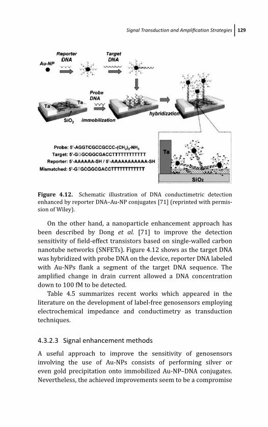
March 14, 2012 20:1 PSP Book - 9in x 6in 04-Ozsoz-c04
Signal Transduction and Amplification Strategies 129
Figure 4.12. Schematic illustration of DNA conductimetric detection
enhanced by reporter DNA–Au-NP conjugates [71] (reprinted with permis-
sion of Wiley).
On the other hand, a nanoparticle enhancement approach has
been described by Dong et al. [71] to improve the detection
sensitivity of field-effect transistors based on single-walled carbon
nanotube networks (SNFETs). Figure 4.12 shows as the target DNA
was hybridized with probe DNA on the device, reporter DNA labeled
with Au-NPs flank a segment of the target DNA sequence. The
amplified change in drain current allowed a DNA concentration
down to 100 fM to be detected.
Table 4.5 summarizes recent works which appeared in the
literature on the development of label-free genosensors employing
electrochemical impedance and conductimetry as transduction
techniques.
4.3.2.3 Signal enhancement methods
A useful approach to improve the sensitivity of genosensors
involving the use of Au-NPs consists of performing silver or
even gold precipitation onto immobilized Au-NP–DNA conjugates.
Nevertheless, the achieved improvements seem to be a compromise
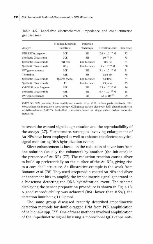
March 14, 2012 20:1 PSP Book - 9in x 6in 04-Ozsoz-c04
130 Gold Nanoparticle-Based Electrochemical DNA Biosensors
Table 4.5. Label-free electrochemical impedance and conductimetric
genosensors
Modified Electrode Detection
Analyte Substrate Technique Detection Limit Reference
DNA PAT transgene GCE EIS 2.4 × 10⁻¹¹ M 72
Synthetic DNA strains GCE EIS 10−12 M 73
Synthetic DNA strands SNFETs Conductance 100 fM 71
Synthetic DNA strands SiO2 Conductance 5 × 10⁻¹⁴ M 68
PAT gene sequence GCE EIS 3.1 × 10⁻¹³ M 21
Thrombin AuE EIS 0.02 nM 70
Synthetic DNA strands Quartz crystal Conductance 5.0 fmol 74
Synthetic DNA strands Pt Conductance 25 pmol 75
CaMV35S gene fragment CPE EIS 2.3 × 10⁻¹³ M 76
Synthetic DNA strands AuE EIS 6.7 × 10⁻¹³ M 15
PAT gene sequence CPE EIS 5.6 × 10⁻¹³ 69
CaMV35S: 35S promoter from cauliflower mosaic virus; CPE: carbon paste electrode; EIS:
electrochemical impedance spectroscopy; GCE: glassy carbon electrode; PAT: phosphinothricin
acetyltransferase; SNFETs: field-effect transistors based on single-walled carbon nanotube
networks.
between the wanted signal augmentation and the reproducibility of
the assays [27]. Furthermore, strategies involving enlargement of
Au-NPs have been employed as well to enhance the electroanalytical
signal monitoring DNA hybridization events.
Silver enhancement is based on the reduction of silver ions from
one solution (usually the enhancer) by another (the initiator) in
the presence of Au-NPs [77]. The reduction reaction causes silver
to build up preferentially on the surface of the Au-NPs, giving rise
to a core-shell structure. An illustrative example is the work from
Bonanni et al. [78]. They used streptavidin-coated Au-NPs and silver
enhancement kits to amplify the impedimetric signal generated in
a biosensor detecting the DNA hybridization event. The scheme
displaying the sensor preparation procedure is shown in Fig. 4.13.
A good reproducibility was achieved (RSD lower than 8.5%), the
detection limit being 11.8 pmol.
The same group discussed recently described impedimetric
detection methods for double-tagged DNA from PCR amplification
of Salmonella spp. [77]. One of these methods involved amplification
of the impedimetric signal by using a monoclonal IgG1kappa anti-

March 14, 2012 20:1 PSP Book - 9in x 6in 04-Ozsoz-c04
Signal Transduction and Amplification Strategies 131
Figure 4.13. Schematic illustration of the experimental procedure fol-
lowed to obtain DNA hybridization sensors based on stretavidin-modified
Au-NPs and silver enhanced detection [78] (reprinted with permission of
Elsevier). See also Color Insert.
digoxigenin antibody (anti-DIG) from mouse able to specifically bind
the digoxigenin-modified end of the amplicon. A secondary anti-
mouse IgG labeled with Au-NPs, able to interact with the anti-
DIG, was then added for signal amplification. A silver enhancement
treatment was carried out by depositing onto the electrode surface
20 mL of a solution obtained by the combination of equal volumes
of enhancer and initiator, and allowing 7 min for the reaction to
proceed. The amplified signal was around 30% higher than the
signal obtained without amplification.
Electrooxidation of hydrazine does not occur on DNA-conjugated
Au-NPs, although it does on bare Au-NPs. However, a chemical
treatment with NaBH4 significantly enhances the electrocatalytic
activity of DNA-conjugated Au-NPs allowing a high signal current
to be obtained for compounds such as H2O2, formic acid, glucose,
or hydrazine [79, 80]. Figure 4.14 shows a schematic view of the
electrochemical DNA detection approach using the NaBH4 enhanced
electrocatalytic activity of Au-NPs. The chemical treatment produces
the adsorption/absorption of a large amount of hydrogen species
on/into Au-NPs, thereby forming an enhanced activity state. This
enhancement process may provide very fast electron-transfer kinet-
ics for hydrazine electrooxidation on Au-NP. A high signal current
was obtained at 0.7 V, whereas the low intrinsic electrocatalytic
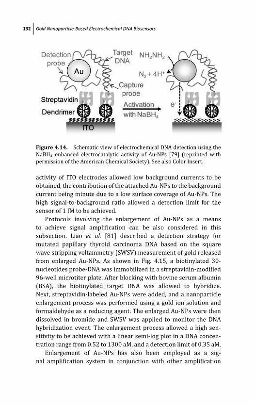
March 14, 2012 20:1 PSP Book - 9in x 6in 04-Ozsoz-c04
132 Gold Nanoparticle-Based Electrochemical DNA Biosensors
Figure 4.14. Schematic view of electrochemical DNA detection using the
NaBH4 enhanced electrocatalytic activity of Au-NPs [79] (reprinted with
permission of the American Chemical Society). See also Color Insert.
activity of ITO electrodes allowed low background currents to be
obtained, the contribution of the attached Au-NPs to the background
current being minute due to a low surface coverage of Au-NPs. The
high signal-to-background ratio allowed a detection limit for the
sensor of 1 fM to be achieved.
Protocols involving the enlargement of Au-NPs as a means
to achieve signal amplification can be also considered in this
subsection. Liao et al. [81] described a detection strategy for
mutated papillary thyroid carcinoma DNA based on the square
wave stripping voltammetry (SWSV) measurement of gold released
from enlarged Au-NPs. As shown in Fig. 4.15, a biotinylated 30-
nucleotides probe-DNA was immobilized in a streptavidin-modified
96-well microtiter plate. After blocking with bovine serum albumin
(BSA), the biotinylated target DNA was allowed to hybridize.
Next, streptavidin-labeled Au-NPs were added, and a nanoparticle
enlargement process was performed using a gold ion solution and
formaldehyde as a reducing agent. The enlarged Au-NPs were then
dissolved in bromide and SWSV was applied to monitor the DNA
hybridization event. The enlargement process allowed a high sen-
sitivity to be achieved with a linear semi-log plot in a DNA concen-
tration range from 0.52 to 1300 aM, and a detection limit of 0.35 aM.
Enlargement of Au-NPs has also been employed as a sig-
nal amplification system in conjunction with other amplification
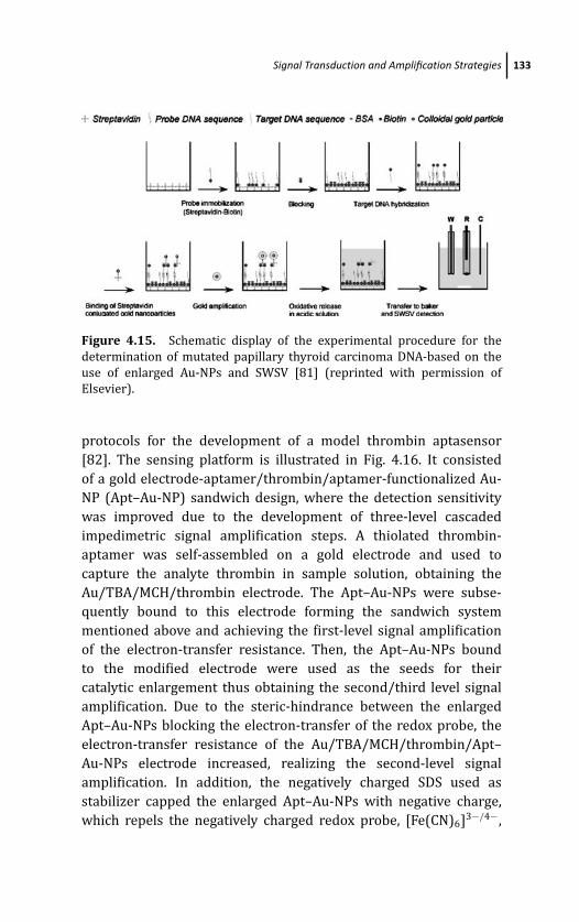
March 14, 2012 20:1 PSP Book - 9in x 6in 04-Ozsoz-c04
Signal Transduction and Amplification Strategies 133
Figure 4.15. Schematic display of the experimental procedure for the
determination of mutated papillary thyroid carcinoma DNA-based on the
use of enlarged Au-NPs and SWSV [81] (reprinted with permission of
Elsevier).
protocols for the development of a model thrombin aptasensor
[82]. The sensing platform is illustrated in Fig. 4.16. It consisted
of a gold electrode-aptamer/thrombin/aptamer-functionalized Au-
NP (Apt–Au-NP) sandwich design, where the detection sensitivity
was improved due to the development of three-level cascaded
impedimetric signal amplification steps. A thiolated thrombin-
aptamer was self-assembled on a gold electrode and used to
capture the analyte thrombin in sample solution, obtaining the
Au/TBA/MCH/thrombin electrode. The Apt–Au-NPs were subse-
quently bound to this electrode forming the sandwich system
mentioned above and achieving the first-level signal amplification
of the electron-transfer resistance. Then, the Apt–Au-NPs bound
to the modified electrode were used as the seeds for their
catalytic enlargement thus obtaining the second/third level signal
amplification. Due to the steric-hindrance between the enlarged
Apt–Au-NPs blocking the electron-transfer of the redox probe, the
electron-transfer resistance of the Au/TBA/MCH/thrombin/Apt–
Au-NPs electrode increased, realizing the second-level signal
amplification. In addition, the negatively charged SDS used as
stabilizer capped the enlarged Apt–Au-NPs with negative charge,
which repels the negatively charged redox probe, [Fe(CN)6]3−/4−,
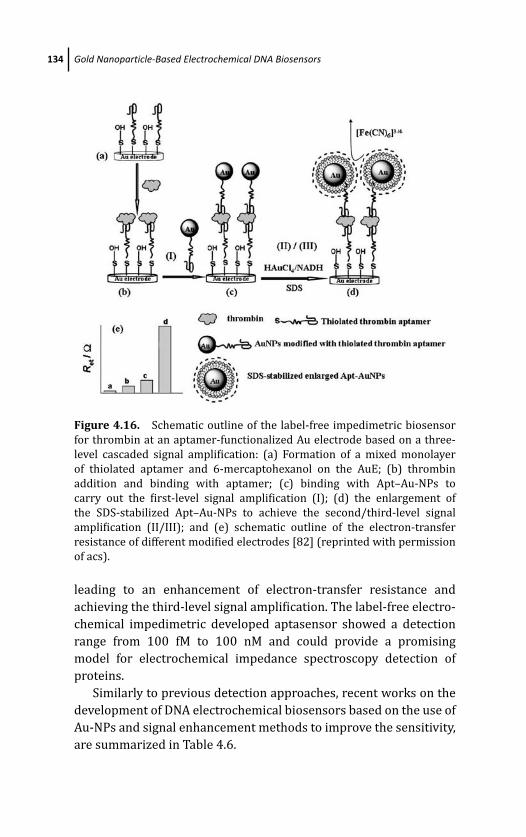
March 14, 2012 20:1 PSP Book - 9in x 6in 04-Ozsoz-c04
134 Gold Nanoparticle-Based Electrochemical DNA Biosensors
Figure 4.16. Schematic outline of the label-free impedimetric biosensor
for thrombin at an aptamer-functionalized Au electrode based on a three-
level cascaded signal amplification: (a) Formation of a mixed monolayer
of thiolated aptamer and 6-mercaptohexanol on the AuE; (b) thrombin
addition and binding with aptamer; (c) binding with Apt–Au-NPs to
carry out the first-level signal amplification (I); (d) the enlargement of
the SDS-stabilized Apt–Au-NPs to achieve the second/third-level signal
amplification (II/III); and (e) schematic outline of the electron-transfer
resistance of different modified electrodes [82] (reprinted with permission
of acs).
leading to an enhancement of electron-transfer resistance and
achieving the third-level signal amplification. The label-free electro-
chemical impedimetric developed aptasensor showed a detection
range from 100 fM to 100 nM and could provide a promising
model for electrochemical impedance spectroscopy detection of
proteins.
Similarly to previous detection approaches, recent works on the
development of DNA electrochemical biosensors based on the use of
Au-NPs and signal enhancement methods to improve the sensitivity,
are summarized in Table 4.6.
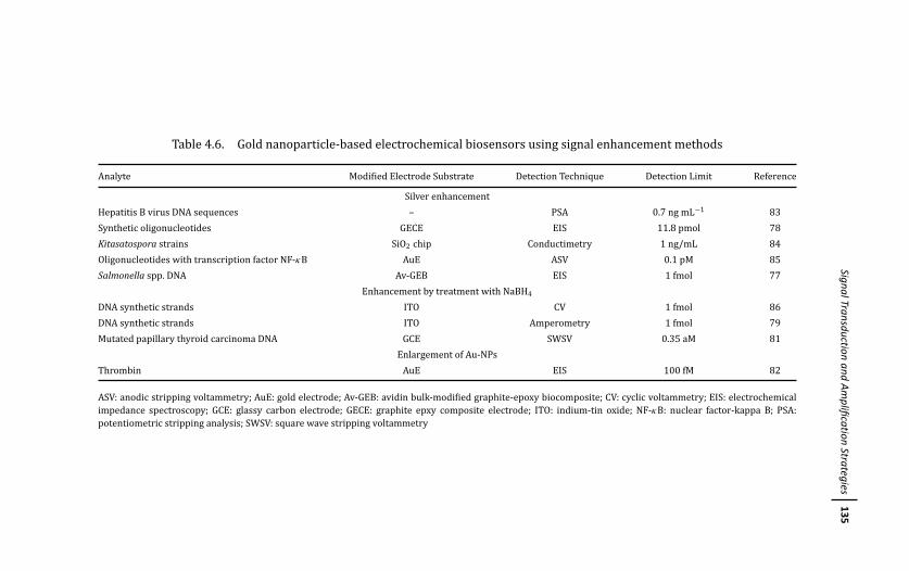
March
14,201220:1
PSPBook
-9inx
6in04-O
zsoz-c04
SignalTransductionand
Amplification
Strategies135
Table 4.6. Gold nanoparticle-based electrochemical biosensors using signal enhancement methods
Analyte Modified Electrode Substrate Detection Technique Detection Limit Reference
Silver enhancement
Hepatitis B virus DNA sequences – PSA 0.7 ng mL−1 83
Synthetic oligonucleotides GECE EIS 11.8 pmol 78
Kitasatospora strains SiO2 chip Conductimetry 1 ng/mL 84
Oligonucleotides with transcription factor NF-κB AuE ASV 0.1 pM 85
Salmonella spp. DNA Av-GEB EIS 1 fmol 77
Enhancement by treatment with NaBH4
DNA synthetic strands ITO CV 1 fmol 86
DNA synthetic strands ITO Amperometry 1 fmol 79
Mutated papillary thyroid carcinoma DNA GCE SWSV 0.35 aM 81
Enlargement of Au-NPs
Thrombin AuE EIS 100 fM 82
ASV: anodic stripping voltammetry; AuE: gold electrode; Av-GEB: avidin bulk-modified graphite-epoxy biocomposite; CV: cyclic voltammetry; EIS: electrochemical
impedance spectroscopy; GCE: glassy carbon electrode; GECE: graphite epxy composite electrode; ITO: indium-tin oxide; NF-κB: nuclear factor-kappa B; PSA:
potentiometric stripping analysis; SWSV: square wave stripping voltammetry
March 14, 2012 20:1 PSP Book - 9in x 6in 04-Ozsoz-c04
136 Gold Nanoparticle-Based Electrochemical DNA Biosensors
4.4 Conclusions and Outlook
The work carried out in the last years show fairly well that
integration of Au-NPs with DNA detection systems allows the
development of genosensors with an improved analytical per-
formance when compared with conventional DNA sensors. Au-
NP–modified electrodes permit a remarkable enhancement of the
amount of DNA immobilized onto the electrode. The efficient DNA
immobilization achieved paves the way for the design of effective
signal transduction approaches of the hybridization event making
use of the different strategies summarized in this chapter. The
amplification routes that the use of Au-NPs facilitates, combined
with electrochemical techniques, allow the design of selective and
highly sensitive DNA sensors. However, looking at the literature, a
lack of applications of these DNA sensing devices to real samples
is observed. The extremely promising prospects on sensitivity and
stability that the gold nanoparticle-based DNA platforms provide
should be validated for solving real analytical problems in order
to demonstrate their competitiveness against conventional DNA
analyses.
Another prospect that can be easily foreseen is the use of
these sensing platforms for multiplexed purposes. Integration of
the genosensors into miniaturized (or even nano) devices involving
microfluidic systems should lead to the efficient and versatile
design of genosensing platforms capable to give multiple adequate
responses to the current analytical demands in the fields such as
the rapid detection of genetic disorders, pollution alarm systems, or
forensic analysis.
Acknowledgments
The financial support of the Spanish Ministry of Science
and Innovation (MICINN) through the projects CTQ2009-
09351, CTQ2009-12650 and DPS2008-07005-C02-01 is gratefully
acknowledged.
March 14, 2012 20:1 PSP Book - 9in x 6in 04-Ozsoz-c04
References 137
References
1. Ch. Kumar (ed.), Nanomaterials for Biosensors Wiley-VCH, Weinheim
(2008).
2. E. Katz, I. Willner, and J. Wang, Electroanalysis 16, 19 (2004).
3. J. M. Pingarron, P. Yanez-Sedeno, and A. Gonzalez Cortes, Electrochim.Acta. 53, 5848 (2008).
4. M. H. Rashid, R. R. Bhattacharjee, A. Kota, and T.K. Mandal, Langmuir 22,
7141 (2006).
5. J. Wang, Ana. Chim. Acta. 500, 247 (2003).
6. H. Cai, C. Xu, P. He, and Y. Fang, J. Electroanal. Chem. 510, 78 (2001).
7. I. Willner, E. Katz, and B. Willner, Amplified and Specific ElectronicTransduction of DNA Sensing Processes in Monolayres and Thin-FilmAssemblies, in Electroanalytical Methods for Biological Materials (A.
Brajter-Toth, J. Q. Chambers, eds.), Marcel Dekker, New York (2002).
8. J. Wang, D. Xu, A. N. Kawde, and R. Polsky, Anal. Chem. 73, 5576 (2001).
9. J. Wang, R. Polsky, and X. Danke, Langmuir 17, 5739 (2001).
10. T. M. H. Lee, L. L. Li, and I. M. Hsing, Lamgmuir 19, 4338 (2003).
11. D. E. Benson, Reagentless biosensors based on nanoparticles,in Nano-materials for Biosensors (Ch. Kumar, ed.), Wiley-VCH, Weinheim (2008).
12. W. C. Liao and J. A. Ho, Anal. Chem. 81, 2470 (2009).
13. T. Garcıa, E. Casero, M. Revenga-Parra, J. Martın Benito, F. Pariente, L.
Vazquez, and E. Lorenzo, Biosens. Bioelectron. 24, 184 (2008).
14. P. R. Brasil de Oliveira Marques, A. Lermo, S. Campoy, H. Yamanaka,
J. Barbe, S. Alegret, and M. Isabel Pividori, Anal. Chem. 81, 1332
(2009).
15. K. Zhang, H. Ma, L. Zhang, and Y. Zhang, Electroanalysis 20, 2127 (2008).
16. L. Shen, Z. Chen, Y. Li, S. He, S. Xie, X.Xu, Z. Liang, et al., Anal. Chem. 80,
6323 (2008).
17. W. Zhang, T. Yang, C. Jiang, and K. Jiao, Appl. Surf. Sci. 254, 4750
(2008).
18. S. Rho, D. Jahng, J. H. Lim, J. Choi, J. H. Chang, S. C. Lee, and K. J. Kim,
Biosens. Bioelectron. 23, 852 (2008).
19. L. Aguı, P. Yanez-Sedeno, and J. M. Pingarron, Anal. Chim. Acta. 622, 11
(2008).
20. H. Ma, L. Zhang, Y. Pan, K. Zhang, and Y. Zhang, Electroanal. 20, 1220
(2008).
March 14, 2012 20:1 PSP Book - 9in x 6in 04-Ozsoz-c04
138 Gold Nanoparticle-Based Electrochemical DNA Biosensors
21. Y. Feng, T. Yang, W. Zhang, C. Jiang, and K. Jiao, Anal. Chim. Acta. 616, 144
(2008).
22. B. Fang, S. Jiao, M. Li, Y. Qu, and X. Jiang, Biosens. Bioelectron. 23, 1175
(2008).
23. Y. Zhang, J. Wang, and M. Xu, Colloids Surf. B: Biointerfaces (2009).
24. E. Suprun, V. Shumyantseva, T. Bulko, S. Rachmetova, S. Rad’ko, N.
Bodoev, and A. Archakov, Biosens. Bioelectron. 24, 825 (2008).
25. G. Li, X. Li, J. Wan, and S. Zhang, Biosens. Bioelectron. 24, 3281 (2009).
26. S. Guo and S. Dong, Trends Anal. Chem. 28, 96 (2009).
27. M. T. Castaneda, S. Alegret, and A. Merkoci, Electroanalysis 19, 743
(2007).
28. S. Guo and E. Wang, Anal. Chim. Acta. 598, 181 (2007).
29. M. A. Rahman, J. I. Son, M. S. Won, and Y. B. Shim, Anal. Chem. 81, 6604
(2009).
30. D. Huang, H. Liu, B. Zhang, K. Jiao, and X. Fu, Microchim. Acta. 165, 243
(2009).
31. J. Kang, X. Li, G. Wu, Z. Wang, and X. Lu, Anal. Biochem. 364, 165 (2007).
32. Z. S. Wu, M. M. Guo, S. B. Zhang, C. R. Chen, J. H. Jiang, G. L. Shen, and R. Q.
Yu, Anal. Chem. 79, 2933 (2007).
33. X. Li, H. Qi, L. Shen, Q. Gao, and C. Zhang, Electroanalysis 20, 1475
(2008).
34. Y. Yang, Z. Zhong, H. Liu, T. Zhu, J. Wu, M. Li, and D. Wang, Electroanalysis20, 2621 (2008).
35. D. Huang, H. Liu, B. Zhang, K. Jiao, and X. Fu, Microchim. Acta. 165, 243
(2009).
36. S. Liu, J. Liu, L. Wang, and F. Zhao, Bioelectrochemistry (2009).
37. L. Ma, R. Yuan, Y. Chai, and S. Chen, J. Mol. Catal. B: Enzym. 56, 215 (2009).
38. X. Wang, T. Yang, and K. Jiao, Biosens. Bioelectron. 25, 668 (2009).
39. P. R. Brasil de Oliveira Marques, A. Lermo, S. Campoy, H. Yamanaka, J.
Barbe, S. Alegret, and M. I. Pividori, Anal. Chem. 81, 1332 (2009).
40. G. Martınez-Paredes, M. B. Gonzalez-Garcıa, and A. Costa-Garcıa,
Electroanalysis 21, 379 (2009).
41. J. Pan, Biochem. Eng. J. 35, 183 (2007).
42. X. Che, R. Yuan, Y. Chai, L. Ma, W. Li, and J. Li, Microchim. Acta. 167, 159
(2009).
43. M. Moreno, E. Rincon, J. M. Perez, V. M. Gonzalez, A. Domingo, and E.
Dominguez, Biosens. Bioelectron. (2009).
March 14, 2012 20:1 PSP Book - 9in x 6in 04-Ozsoz-c04
References 139
44. P. Du, H. Li, Z. Mei, and S. Liu, Bioelectrochemistry 75, 37 (2009).
45. Y. Du, B. Li, F. Wang, and S. Dong, Biosens. Bioelectron. 24, 1979 (2009).
46. Y. Zhang, H. Ma, K. Zhang, S. Zhang, and J. Wang, Electrochim. Acta. 54,
2385 (2009).
47. D. Li, Y. Yan, A. Wieckowska, and I. Willner, Chem. Commun. 3544
(2007).
48. K. Feng, C. Sun, Y. Kan, J. Chen, J. H. Jiang, G. L. Shen, and R. Q. Yu,
Electrochem. Commun. 10, 531 (2008).
49. Y. Kang, K. J. Feng, J. W. Chen, J. H. Jiang, G. L. Shen, and R. Q. Yu,
Bioelectrochemistry 73, 76 (2008).
50. C. Ding, Q. Zhang, J. M. Lin and S. S. Zhang, Biosens. Bioelectron. 24, 3140
(2009).
51. P. Du, H. Li, and W. Cao, Biosens. Bioelectron. 24, 3223 (2009).
52. P. Miao, L. Liu, Y. Nie, and G. Li, Biosens. Bioelectron. 24, 3347 (2009).
53. T. L. Chang, Y. W. Lee, C. C. Chen, and F. H. Ko, Microelectron. Engineer 84,
1698 (2007).
54. P. He, L. Shen, Y. Cao, and D. Li, Anal. Chem. 79, 8024 (2007).
55. Y. Jin, W. Lu, J. Hu, X. Yao, and J. Li, Electrochem. Commun. 9, 1086 (2007).
56. J. Zhang, S. Song, L. Wang, D. Pan, and C. Fan, Nature Protocols 2, 2888
(2007).
57. K. Hu, D. Lan, X. Li, and S. Zhang, Anal. Chem. 80, 9124 (2008).
58. M. J. A. Shiddiky, Md. A. Rahman, C. S. Cheol, and Y. B. Shim, Anal. Biochem.379, 170 (2008).
59. S. Zhang, J. Xia, and X. Li, Anal. Chem. 80, 8382 (2008).
60. J. Zhao, X. Zhu, T. Li, and G. Li, Analyst 133, 1242 (2008).
61. X. Zhang, B. Qi, Y. Li, and S. Zhang, Biosens. Bioelectron. 25, 259 (2009).
62. Z. Zhu, Y. Su, J. Li, D. Li, J. Zhang, S. Song, Y. Zhao, G. Li, and C. Fan, Anal.Chem. 81, 7660 (2009).
63. W. Li, Z. Nie, X. Xu, Q. Shen, C. Deng, J. Chen, and S. Yao, Talanta 78, 954
(2009).
64. J. Wang, W. Meng, X. Zheng, S. Liu, and G. Li, Biosens. Bioelectron. 24, 1598
(2009).
65. S. Pinijsuwan, P. Rijiravanich, M. Somasundrum, and W. Surareungchai,
Anal. Chem. 80, 6779 (2008).
66. M. T. Castaneda, A. Merkoci, M. Pumera, and S. Alegret, Biosens.Bioelectron. 22, 1961 (2007).
March 14, 2012 20:1 PSP Book - 9in x 6in 04-Ozsoz-c04
140 Gold Nanoparticle-Based Electrochemical DNA Biosensors
67. J. Zheng, W. Feng, L. Lin, F. Zhang, G. Cheng, P. He, and Y. Fang, Biosens.Bioelectron. 23, 341 (2007).
68. C. Fang, Y. Fan, J. Kong, Z. Gao, and N. Balasubramanian, Anal. Chem. 80,
9387 (2008).
69. N. Zhou, T. Yang, C. Jiang, M. Du, and K. Jiao, Talanta 77, 1021 (2009).
70. B. Li, Y. Wang, H. Wei, and S. Dong, Biosens. Bioelectron. 23, 965 (2008).
71. X. Dong, C. M. Lau, A. Lohani, S. G. Mhaisalkar, J. Kasim, Z. Shen, X. Ho, J.
A. Rogers, and L. J. Li, Adv. Mater. 20, 2389 (2008).
72. J. Yang, T. Yang, Y. Feng, and K. Jiao, Anal. Biochem. 365, 24 (2007).
73. O. Arotiba, J. Owino, E. Songa, N. Hendricks, T. Waryo, N. Jahed, P. Baker,
and E. Iwuoha, Sensors 8, 6791 (2008).
74. S. Tokonami, H. Shiigi, and T. Nagaoka, Anal. Chem. 80, 8071 (2008).
75. S. Tokonami, H. Shiigi, and T. Nagaoka, Electroanalysis 20, 355 (2008).
76. Y. C. Zhang, T. Yang, N. Zhou, W. Zhang, and K. Jiao, Sci. China Ser. B-Chem.51, 1066 (2008).
77. A. Bonanni, M. I. Pividori, S. Campoy, J. Barbe, and M. del Valle, Analyst134, 602 (2009).
78. A. Bonanni, M. J. Esplandiu, and M. Del Valle, Electrochim. Acta. 53, 4022
(2008).
79. J. Das and H. Yang, J. Phys. Chem. C 113, 6093 (2009).
80. J. Das, S. Patra, and H. Yang, Chem. Commun. 4451 (2008).
81. K. T. Liao, J. T. Cheng, C. L. Li, R. T. Liu, and H. J. Juang, Biosens. Bioelectron.24, 1899 (2009).
82. C. Deng, J. Chen, Z. Nie, M. Wang, X. Xhu, X. Chen, X. Xiao, C. Lei, and S.
Yao, Anal. Chem. 81, 739 (2009).
83. H. Hanaee, H. Ghourchian, and A. A. Zhiaee, Anal. Biochem. 370, 195
(2007).
84. R. Moller, T. Schuler, S. Gunther, M. R. Carlsohn, and T. Munder, Appl.Microbiol. Biotechnol. 77, 1181 (2008).
85. Q. Pan, R. Zhang, Y. Bai, N. He, and Z. Lu, Anal. Biochem. 375, 179 (2008).
86. T. Selvaraju, J. Das, K. Jo, K. Kwon, C. H. Huh, T. K. Kim, and H. Yang,
Langmuir 24, 9883 (2008).
March 14, 2012 20:7 PSP Book - 9in x 6in 05-Ozsoz-c05
Chapter 5
Nanoparticle-Induced Catalysis forElectrochemical DNA Biosensors
Marisa Maltez-da Costa,a Alfredo de la Escosura-Muniz,a
and Arben Merkocia,b
aNanobioelectronics & Biosensors Group, Institut Catala de Nanotecnologia,CIN2 (ICN-CSIC), Esfera Universitat Autonoma de Barcelona, Bellaterra,Barcelona, SpainbICREA, Barcelona, [email protected]
In this chapter, the use of nanoparticles (NPs) in catalytic
electrochemical analysis of DNA as a new detection strategy
reported in recent years is revised. The topics covered here
include labeling with nanoparticles and their subsequent signal
enhancement employed for DNA hybridization detection. Direct
sensing of nanoparticle labels as well as indirect detection routes
through electrochemical sensing of label-catalyzed reactions have
been reported. Nanofabrication of platforms used for the detection
of DNA through electrochemical signal amplification has also
been revised. Some recent examples of interesting nanoparticle-
induced catalytic methodologies applied for protein detection using
electrochemical biosensors are also given, because of their potential
interest in future applications in DNA detection.
Electrochemical DNA BiosensorsEdited by Mehmet OzsozCopyright c© 2012 Pan Stanford Publishing Pte. Ltd.ISBN 978-981-4241-77-9 (Hardcover), 978-981-4303-98-9 (eBook)www.panstanford.com
March 14, 2012 20:7 PSP Book - 9in x 6in 05-Ozsoz-c05
142 Nanoparticle-Induced Catalysis for Electrochemical DNA Biosensors
5.1 Introduction
Various nanomaterials, including carbon nanotubes, nanoparticles,
nanomagnetic beads, and nanocomposites, are being used to
develop highly sensitive and robust biosensors and biosensing
systems [1] with a special emphasis on the development of
electrochemical-based (bio)sensors [2, 3] due to their simplicity and
cost efficiency.
One of the main requirements for a good performance of
a biosensor is the high sensitivity of the response. This is of
great importance when, for example, it is required to use the
biosensor in clinical diagnostics for the detection of low levels of
clinical biomarkers in human fluids [4], because in most cases the
biomarker to be detected is present in very low concentrations. The
need for biosensing systems that can detect these markers with high
sensitivity without loss of selectivity, that is, low detection limits
with high reliability and superior reproducibility, is becoming an
important challenge.
The amplified detection of biorecognition events and specifically
of DNA hybridization events stands out of the biosensing field,
because it is one of the most important objectives of the current
bioanalytical chemistry. In this context, approaching the catalytic
properties of some (bio)materials appears to be a promising way to
enhance the sensitivity of the bioassays.
Catalysts are materials that change the rate of chemical reactions
without being consumed in the process. Because of their huge
economical contribution, by lowering the costs of several processes,
they are actually one of most wanted materials and can be found in
manufacturing processes, fuel cells, combustion devices, pollution
control systems, food processing, and sensor systems. Catalysts are
generally prepared from transition metals, most of them from the
platinum group, but this fact still represents a high cost due to the
material expensiveness, and thus a reduction in used amounts would
be appreciated [5, 6].
The coupling of enzymes as biocatalytic amplifying labels is a
generated paradigm in developing bioelectronic sensing devices.
The biocatalytic generation of a redox product upon binding of
the label to the recognition event, the incorporation of redox

March 14, 2012 20:7 PSP Book - 9in x 6in 05-Ozsoz-c05
Introduction 143
mediators into DNA assemblies that activate bioelectrocatalytic
transformations, or the use of enzyme labels that yield an insoluble
product on electrode surfaces has been extensively used to amplify
biorecognition events. Due to the several problems associated with
these techniques and the fast development in nanotechnology,
nanoparticle-assisted signal enhancement for DNA biosensors has
been greatly developed in the last decade [7, 8, 9, 10, 11].
In electrochemical sensors, electrocatalytic procedures can be
approached in two ways, either by using an electrode that have
highly or moderately electrocatalytic properties, or by exploiting
a significant change in the electrocatalytic activity of an electrode
during the detection process. Gold and platinum are commonly
employed as highly electrocatalytic electrodes. Although these elec-
trodes allow fast electron-transfer kinetics for most electroactive
species, their background currents are high and fluctuate with the
applied potential, which may make difficult to obtain the high signal-
to-background ratios, required to achieve low detection limits. In
recent years, moderately electrocatalytic electrodes have been used
to obtain high signal-to-background ratios. Such electrodes can be
obtained by modifying a poorly electrocatalytic electrode with a low
coverage of a highly electrocatalytic material. For example, indium-
tin oxide (ITO) electrodes modified with a partial monolayer of
ferrocene, carbon nanotubes, or gold nanoparticles (Au-NPs) have
been employed [7, 11].
The actual knowledge concerning the special properties of NPs
arises from the numerous studies related to the effects of changes
in shape and size on the general properties of materials. From the
electroanalysis point of view the major features resulting from these
studies are enhancement of mass transport, high catalytic activity,
high effective surface area, and control over local microenvironment
at the electrode surface [8, 12, 13, 14].
The development of nanotechnology during the last decades has
led scientists to fabricate and analyze catalysts at the nanoscale.
These nanostructured materials are usually high-surface-area met-
als or semiconductors in the form of NPs with excellent catalytic
properties due to the high ratio of surface atoms with free valences
to the cluster of total atoms. The catalysis takes place on the
active surface sites of metal clusters in a similar mechanism as the
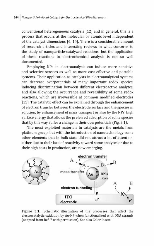
March 14, 2012 20:7 PSP Book - 9in x 6in 05-Ozsoz-c05
144 Nanoparticle-Induced Catalysis for Electrochemical DNA Biosensors
conventional heterogeneous catalysis [12] and in general, this is a
process that occurs at the molecular or atomic level independent
of the catalyst dimensions [6, 14]. There is a considerable amount
of research articles and interesting reviews in what concerns to
the study of nanoparticle-catalyzed reactions, but the application
of these reactions in electrochemical analysis is not so well
documented.
Employing NPs in electroanalysis can induce more sensitive
and selective sensors as well as more cost-effective and portable
systems. Their application as catalysts in electroanalytical systems
can decrease overpotentials of many important redox species,
inducing discrimination between different electroactive analytes,
and also allowing the occurrence and reversibility of some redox
reactions, which are irreversible at common modified electrodes
[15]. The catalytic effect can be explained through the enhancement
of electron transfer between the electrode surface and the species in
solution, by enhancement of mass transport or also by the NPs’ high
surface energy that allows the preferred adsorption of some species
that by this way suffer a change in their overpotentials (Fig. 5.1).
The most exploited materials in catalysis are the metals from
platinum group, but with the introduction of nanotechnology some
other elements that in bulk state did not attract a lot of attention,
either due to their lack of reactivity toward some analytes or due to
their high costs in production, are now emerging.
Figure 5.1. Schematic illustration of the processes that affect the
electrocatalytic oxidation by Au-NP when functionalized with DNA strands
(adapted from Ref. 7 with permission). See also Color Insert.
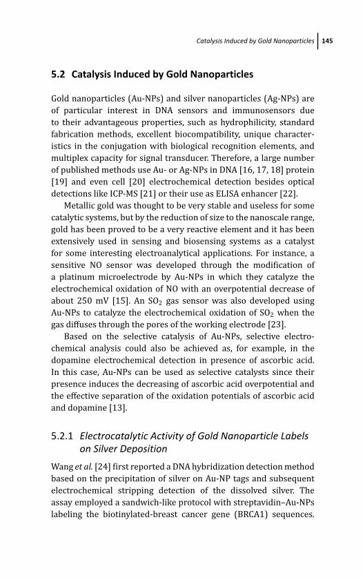
March 14, 2012 20:7 PSP Book - 9in x 6in 05-Ozsoz-c05
Catalysis Induced by Gold Nanoparticles 145
5.2 Catalysis Induced by Gold Nanoparticles
Gold nanoparticles (Au-NPs) and silver nanoparticles (Ag-NPs) are
of particular interest in DNA sensors and immunosensors due
to their advantageous properties, such as hydrophilicity, standard
fabrication methods, excellent biocompatibility, unique character-
istics in the conjugation with biological recognition elements, and
multiplex capacity for signal transducer. Therefore, a large number
of published methods use Au- or Ag-NPs in DNA [16, 17, 18] protein
[19] and even cell [20] electrochemical detection besides optical
detections like ICP-MS [21] or their use as ELISA enhancer [22].
Metallic gold was thought to be very stable and useless for some
catalytic systems, but by the reduction of size to the nanoscale range,
gold has been proved to be a very reactive element and it has been
extensively used in sensing and biosensing systems as a catalyst
for some interesting electroanalytical applications. For instance, a
sensitive NO sensor was developed through the modification of
a platinum microelectrode by Au-NPs in which they catalyze the
electrochemical oxidation of NO with an overpotential decrease of
about 250 mV [15]. An SO2 gas sensor was also developed using
Au-NPs to catalyze the electrochemical oxidation of SO2 when the
gas diffuses through the pores of the working electrode [23].
Based on the selective catalysis of Au-NPs, selective electro-
chemical analysis could also be achieved as, for example, in the
dopamine electrochemical detection in presence of ascorbic acid.
In this case, Au-NPs can be used as selective catalysts since their
presence induces the decreasing of ascorbic acid overpotential and
the effective separation of the oxidation potentials of ascorbic acid
and dopamine [13].
5.2.1 Electrocatalytic Activity of Gold Nanoparticle Labelson Silver Deposition
Wang et al. [24] first reported a DNA hybridization detection method
based on the precipitation of silver on Au-NP tags and subsequent
electrochemical stripping detection of the dissolved silver. The
assay employed a sandwich-like protocol with streptavidin–Au-NPs
labeling the biotinylated-breast cancer gene (BRCA1) sequences.
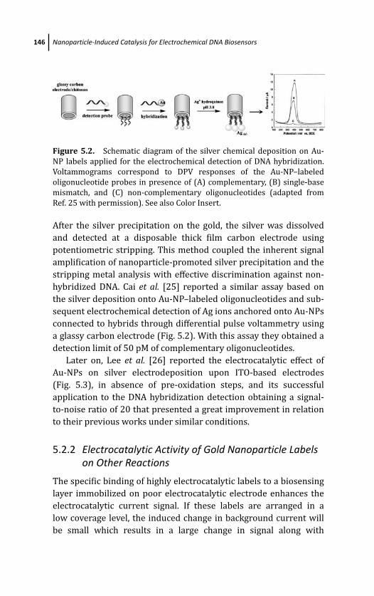
March 14, 2012 20:7 PSP Book - 9in x 6in 05-Ozsoz-c05
146 Nanoparticle-Induced Catalysis for Electrochemical DNA Biosensors
Figure 5.2. Schematic diagram of the silver chemical deposition on Au-
NP labels applied for the electrochemical detection of DNA hybridization.
Voltammograms correspond to DPV responses of the Au-NP–labeled
oligonucleotide probes in presence of (A) complementary, (B) single-base
mismatch, and (C) non-complementary oligonucleotides (adapted from
Ref. 25 with permission). See also Color Insert.
After the silver precipitation on the gold, the silver was dissolved
and detected at a disposable thick film carbon electrode using
potentiometric stripping. This method coupled the inherent signal
amplification of nanoparticle-promoted silver precipitation and the
stripping metal analysis with effective discrimination against non-
hybridized DNA. Cai et al. [25] reported a similar assay based on
the silver deposition onto Au-NP–labeled oligonucleotides and sub-
sequent electrochemical detection of Ag ions anchored onto Au-NPs
connected to hybrids through differential pulse voltammetry using
a glassy carbon electrode (Fig. 5.2). With this assay they obtained a
detection limit of 50 pM of complementary oligonucleotides.
Later on, Lee et al. [26] reported the electrocatalytic effect of
Au-NPs on silver electrodeposition upon ITO-based electrodes
(Fig. 5.3), in absence of pre-oxidation steps, and its successful
application to the DNA hybridization detection obtaining a signal-
to-noise ratio of 20 that presented a great improvement in relation
to their previous works under similar conditions.
5.2.2 Electrocatalytic Activity of Gold Nanoparticle Labelson Other Reactions
The specific binding of highly electrocatalytic labels to a biosensing
layer immobilized on poor electrocatalytic electrode enhances the
electrocatalytic current signal. If these labels are arranged in a
low coverage level, the induced change in background current will
be small which results in a large change in signal along with
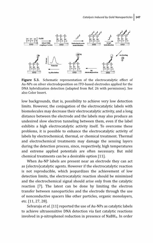
March 14, 2012 20:7 PSP Book - 9in x 6in 05-Ozsoz-c05
Catalysis Induced by Gold Nanoparticles 147
Figure 5.3. Schematic representation of the electrocatalytic effect of
Au-NPs on silver electrodeposition on ITO-based electrodes applied for the
DNA hybridization detection (adapted from Ref. 26 with permission). See
also Color Insert.
low backgrounds, that is, possibility to achieve very low detection
limits. However, the conjugation of the electrocatalytic labels with
biomolecules may decrease their electrocatalytic activity, and a long
distance between the electrode and the labels may also produce an
undesired slow electron tunneling between them, even if the label
exhibits a high electrocatalytic activity itself. To overcome these
problems, it is possible to enhance the electrocatalytic activity of
labels by electrochemical, thermal, or chemical treatment. Thermal
and electrochemical treatments may damage the sensing layers
during the detection process, since, respectively, high temperatures
and extreme applied potentials are often necessary. But mild
chemical treatments can be a desirable option [11].
When Au-NP labels are present near an electrode they can act
as (electro)catalytic agents. However if the electrocatalytic reaction
is not reproducible, which jeopardizes the achievement of low
detection limits, the electrocatalytic reaction should be minimized
and the electrochemical signal should arise only from the catalytic
reaction [7]. The latest can be done by limiting the electron
transfer between nanoparticles and the electrode through the use
of nonconductive spacers like other particles, organic monolayers,
etc. [11, 27, 28].
Selvaraju et al. [11] reported the use of Au-NPs as catalytic labels
to achieve ultrasensitive DNA detection via fast catalytic reactions
involved in p-nitrophenol reduction in presence of NaBH4. In order
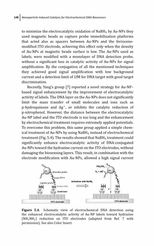
March 14, 2012 20:7 PSP Book - 9in x 6in 05-Ozsoz-c05
148 Nanoparticle-Induced Catalysis for Electrochemical DNA Biosensors
to minimize the electrocatalytic oxidation of NaBH4 by Au-NPs they
used magnetic beads as capture probe immobilization platforms
that acted also as spacers between Au-NPs and the ferrocene-
modified ITO electrode, achieving this effect only when the density
of Au-NPs at magnetic beads surface is low. The Au-NPs used as
labels, were modified with a monolayer of DNA detection probe,
without a significant loss in catalytic activity of Au-NPs for signal
amplification. By the conjugation of all the mentioned techniques
they achieved good signal amplification with low background
current and a detection limit of 1fM for DNA target with good target
discrimination.
Recently, Yang’s group [7] reported a novel strategy for Au-NP–
based signal enhancement by the improvement of electrocatalytic
activity of labels. The DNA layer on the Au-NPs does not significantly
limit the mass transfer of small molecules and ions such as
p-hydroquinone and Ag+, or inhibits the catalytic reduction of
p-nitrophenol. However, the distance between the electrocatalytic
Au-NP label and the ITO electrode is too long and the enhancement
by electrochemical treatment requires extremely applied potentials.
To overcome this problem, this same group applied a simple chem-
ical treatment of Au-NPs by using NaBH4 instead of electrochemical
treatment (Fig. 5.4). The results showed that NaBH4 treatment could
significantly enhance electrocatalytic activity of DNA-conjugated
Au-NPs toward the hydrazine current on the ITO electrodes, without
damaging the biosensing layers. This result, in combination with the
electrode modification with Au-NPs, allowed a high signal current
Figure 5.4. Schematic view of electrochemical DNA detection using
the enhanced electrocatalytic activity of Au-NP labels toward hydrazine
(NH2NH2) reduction on ITO electrodes (adapted from Ref. 7 with
permission). See also Color Insert.
March 14, 2012 20:7 PSP Book - 9in x 6in 05-Ozsoz-c05
Catalysis Induced by Platinum and Palladium Nanoparticles 149
whereas the low intrinsic electrocatalytic activity of ITO electrodes
minimized the background current. With this method, 1fM of target
DNA in an electrochemical DNA sensor was detected without the
need of target or enzymatic signal amplification [29].
5.2.3 Electrocatalytic Activity of Gold Nanoparticles Usedas Modifiers of Electrotransducer Surfaces
Another application of metal nanoparticles in electrochemical
detection of DNA is their incorporation with composites used as
electrode surface modifiers. Even though these modified electrodes
can show higher background signals than the unmodified electrodes,
the incorporation of Au-NPs can be used to promote selective
immobilization spots to well-oriented DNA detection probes.
Liu et al. [9] have recently reported the application of composites
of Au-NPs and multi-walled carbon nanotubes (Au-NPs/MWCNT)
for enhancing the electrochemical detection of DNA hybridization.
Au-NPs were deposited onto the surface of MWCNTs by one-step
reaction and then a thiolated-DNA probe was immobilized onto the
Au-NPs/MWCNTs–modified glassy carbon electrode (GCE) through
the strong gold–sulfur linkage, which could control the molecular
orientation of probe DNA. On the basis of DNA detection it was
found that the Au-NP/MWCNT composites could highly improve the
sensitivity of DNA biosensor due to their enhanced conductivity and
increased effective surface area. Furthermore, it was revealed that
selectivity and reproducibility of the DNA sensor were also excellent,
which resulted in a significant platform for the hybridization
detection of DNA.
5.3 Catalysis Induced by Platinum andPalladium Nanoparticles
5.3.1 Electrocatalytic Activity of Platinum NanoparticleLabels
Despite the high cost of this metal in the bulk state, the subsequent
saving that reducing the metal size implies placed platinum
nanoparticles (Pt-NPs) in the centre of attention of scientists due to
their ability to be used as catalyst for many industrial processes [13].
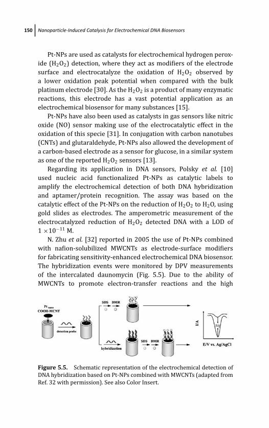
March 14, 2012 20:7 PSP Book - 9in x 6in 05-Ozsoz-c05
150 Nanoparticle-Induced Catalysis for Electrochemical DNA Biosensors
Pt-NPs are used as catalysts for electrochemical hydrogen perox-
ide (H2O2) detection, where they act as modifiers of the electrode
surface and electrocatalyze the oxidation of H2O2 observed by
a lower oxidation peak potential when compared with the bulk
platinum electrode [30]. As the H2O2 is a product of many enzymatic
reactions, this electrode has a vast potential application as an
electrochemical biosensor for many substances [15].
Pt-NPs have also been used as catalysts in gas sensors like nitric
oxide (NO) sensor making use of the electrocatalytic effect in the
oxidation of this specie [31]. In conjugation with carbon nanotubes
(CNTs) and glutaraldehyde, Pt-NPs also allowed the development of
a carbon-based electrode as a sensor for glucose, in a similar system
as one of the reported H2O2 sensors [13].
Regarding its application in DNA sensors, Polsky et al. [10]
used nucleic acid functionalized Pt-NPs as catalytic labels to
amplify the electrochemical detection of both DNA hybridization
and aptamer/protein recognition. The assay was based on the
catalytic effect of the Pt-NPs on the reduction of H2O2 to H2O, using
gold slides as electrodes. The amperometric measurement of the
electrocatalyzed reduction of H2O2 detected DNA with a LOD of
1 ×10⁻¹¹ M.
N. Zhu et al. [32] reported in 2005 the use of Pt-NPs combined
with nafion-solubilized MWCNTs as electrode-surface modifiers
for fabricating sensitivity-enhanced electrochemical DNA biosensor.
The hybridization events were monitored by DPV measurements
of the intercalated daunomycin (Fig. 5.5). Due to the ability of
MWCNTs to promote electron-transfer reactions and the high
Figure 5.5. Schematic representation of the electrochemical detection of
DNA hybridization based on Pt-NPs combined with MWCNTs (adapted from
Ref. 32 with permission). See also Color Insert.
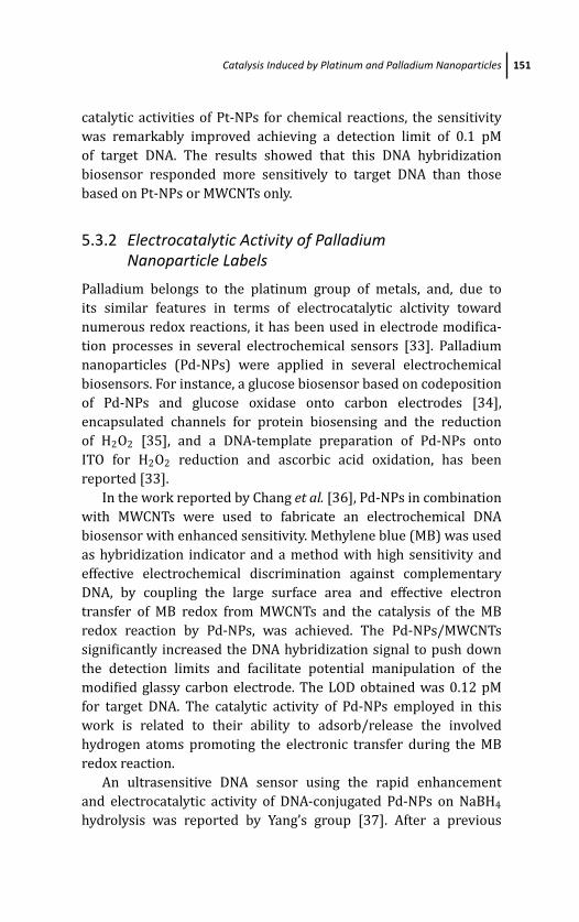
March 14, 2012 20:7 PSP Book - 9in x 6in 05-Ozsoz-c05
Catalysis Induced by Platinum and Palladium Nanoparticles 151
catalytic activities of Pt-NPs for chemical reactions, the sensitivity
was remarkably improved achieving a detection limit of 0.1 pM
of target DNA. The results showed that this DNA hybridization
biosensor responded more sensitively to target DNA than those
based on Pt-NPs or MWCNTs only.
5.3.2 Electrocatalytic Activity of PalladiumNanoparticle Labels
Palladium belongs to the platinum group of metals, and, due to
its similar features in terms of electrocatalytic alctivity toward
numerous redox reactions, it has been used in electrode modifica-
tion processes in several electrochemical sensors [33]. Palladium
nanoparticles (Pd-NPs) were applied in several electrochemical
biosensors. For instance, a glucose biosensor based on codeposition
of Pd-NPs and glucose oxidase onto carbon electrodes [34],
encapsulated channels for protein biosensing and the reduction
of H2O2 [35], and a DNA-template preparation of Pd-NPs onto
ITO for H2O2 reduction and ascorbic acid oxidation, has been
reported [33].
In the work reported by Chang et al. [36], Pd-NPs in combination
with MWCNTs were used to fabricate an electrochemical DNA
biosensor with enhanced sensitivity. Methylene blue (MB) was used
as hybridization indicator and a method with high sensitivity and
effective electrochemical discrimination against complementary
DNA, by coupling the large surface area and effective electron
transfer of MB redox from MWCNTs and the catalysis of the MB
redox reaction by Pd-NPs, was achieved. The Pd-NPs/MWCNTs
significantly increased the DNA hybridization signal to push down
the detection limits and facilitate potential manipulation of the
modified glassy carbon electrode. The LOD obtained was 0.12 pM
for target DNA. The catalytic activity of Pd-NPs employed in this
work is related to their ability to adsorb/release the involved
hydrogen atoms promoting the electronic transfer during the MB
redox reaction.
An ultrasensitive DNA sensor using the rapid enhancement
and electrocatalytic activity of DNA-conjugated Pd-NPs on NaBH4
hydrolysis was reported by Yang’s group [37]. After a previous
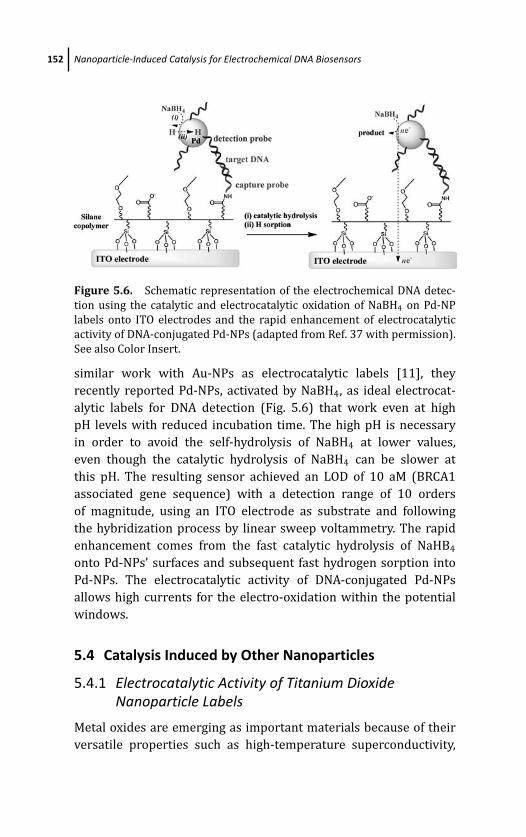
March 14, 2012 20:7 PSP Book - 9in x 6in 05-Ozsoz-c05
152 Nanoparticle-Induced Catalysis for Electrochemical DNA Biosensors
Figure 5.6. Schematic representation of the electrochemical DNA detec-
tion using the catalytic and electrocatalytic oxidation of NaBH4 on Pd-NP
labels onto ITO electrodes and the rapid enhancement of electrocatalytic
activity of DNA-conjugated Pd-NPs (adapted from Ref. 37 with permission).
See also Color Insert.
similar work with Au-NPs as electrocatalytic labels [11], they
recently reported Pd-NPs, activated by NaBH4, as ideal electrocat-
alytic labels for DNA detection (Fig. 5.6) that work even at high
pH levels with reduced incubation time. The high pH is necessary
in order to avoid the self-hydrolysis of NaBH4 at lower values,
even though the catalytic hydrolysis of NaBH4 can be slower at
this pH. The resulting sensor achieved an LOD of 10 aM (BRCA1
associated gene sequence) with a detection range of 10 orders
of magnitude, using an ITO electrode as substrate and following
the hybridization process by linear sweep voltammetry. The rapid
enhancement comes from the fast catalytic hydrolysis of NaHB4
onto Pd-NPs’ surfaces and subsequent fast hydrogen sorption into
Pd-NPs. The electrocatalytic activity of DNA-conjugated Pd-NPs
allows high currents for the electro-oxidation within the potential
windows.
5.4 Catalysis Induced by Other Nanoparticles
5.4.1 Electrocatalytic Activity of Titanium DioxideNanoparticle Labels
Metal oxides are emerging as important materials because of their
versatile properties such as high-temperature superconductivity,
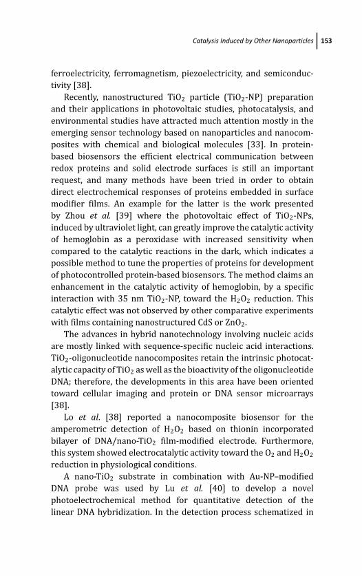
March 14, 2012 20:7 PSP Book - 9in x 6in 05-Ozsoz-c05
Catalysis Induced by Other Nanoparticles 153
ferroelectricity, ferromagnetism, piezoelectricity, and semiconduc-
tivity [38].
Recently, nanostructured TiO2 particle (TiO2-NP) preparation
and their applications in photovoltaic studies, photocatalysis, and
environmental studies have attracted much attention mostly in the
emerging sensor technology based on nanoparticles and nanocom-
posites with chemical and biological molecules [33]. In protein-
based biosensors the efficient electrical communication between
redox proteins and solid electrode surfaces is still an important
request, and many methods have been tried in order to obtain
direct electrochemical responses of proteins embedded in surface
modifier films. An example for the latter is the work presented
by Zhou et al. [39] where the photovoltaic effect of TiO2-NPs,
induced by ultraviolet light, can greatly improve the catalytic activity
of hemoglobin as a peroxidase with increased sensitivity when
compared to the catalytic reactions in the dark, which indicates a
possible method to tune the properties of proteins for development
of photocontrolled protein-based biosensors. The method claims an
enhancement in the catalytic activity of hemoglobin, by a specific
interaction with 35 nm TiO2-NP, toward the H2O2 reduction. This
catalytic effect was not observed by other comparative experiments
with films containing nanostructured CdS or ZnO2.
The advances in hybrid nanotechnology involving nucleic acids
are mostly linked with sequence-specific nucleic acid interactions.
TiO2-oligonucleotide nanocomposites retain the intrinsic photocat-
alytic capacity of TiO2 as well as the bioactivity of the oligonucleotide
DNA; therefore, the developments in this area have been oriented
toward cellular imaging and protein or DNA sensor microarrays
[38].
Lo et al. [38] reported a nanocomposite biosensor for the
amperometric detection of H2O2 based on thionin incorporated
bilayer of DNA/nano-TiO2 film-modified electrode. Furthermore,
this system showed electrocatalytic activity toward the O2 and H2O2
reduction in physiological conditions.
A nano-TiO2 substrate in combination with Au-NP–modified
DNA probe was used by Lu et al. [40] to develop a novel
photoelectrochemical method for quantitative detection of the
linear DNA hybridization. In the detection process schematized in
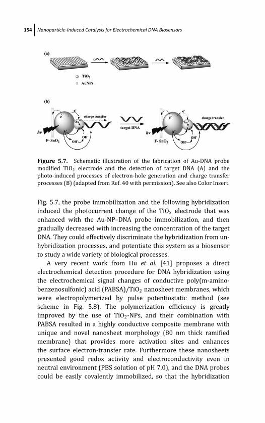
March 14, 2012 20:7 PSP Book - 9in x 6in 05-Ozsoz-c05
154 Nanoparticle-Induced Catalysis for Electrochemical DNA Biosensors
Figure 5.7. Schematic illustration of the fabrication of Au-DNA probe
modified TiO2 electrode and the detection of target DNA (A) and the
photo-induced processes of electron-hole generation and charge transfer
processes (B) (adapted from Ref. 40 with permission). See also Color Insert.
Fig. 5.7, the probe immobilization and the following hybridization
induced the photocurrent change of the TiO2 electrode that was
enhanced with the Au-NP–DNA probe immobilization, and then
gradually decreased with increasing the concentration of the target
DNA. They could effectively discriminate the hybridization from un-
hybridization processes, and potentiate this system as a biosensor
to study a wide variety of biological processes.
A very recent work from Hu et al. [41] proposes a direct
electrochemical detection procedure for DNA hybridization using
the electrochemical signal changes of conductive poly(m-amino-
benzenosulfonic) acid (PABSA)/TiO2 nanosheet membranes, which
were electropolymerized by pulse potentiostatic method (see
scheme in Fig. 5.8). The polymerization efficiency is greatly
improved by the use of TiO2-NPs, and their combination with
PABSA resulted in a highly conductive composite membrane with
unique and novel nanosheet morphology (80 nm thick ramified
membrane) that provides more activation sites and enhances
the surface electron-transfer rate. Furthermore these nanosheets
presented good redox activity and electroconductivity even in
neutral environment (PBS solution of pH 7.0), and the DNA probes
could be easily covalently immobilized, so that the hybridization
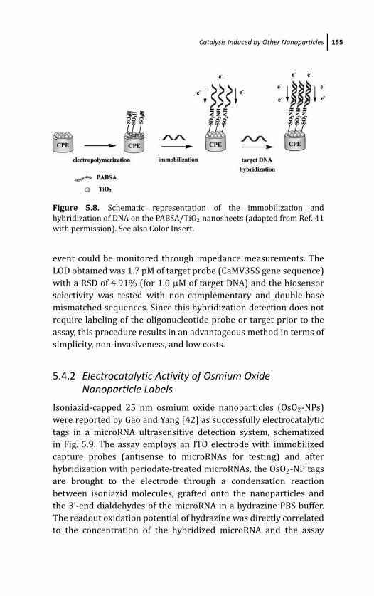
March 14, 2012 20:7 PSP Book - 9in x 6in 05-Ozsoz-c05
Catalysis Induced by Other Nanoparticles 155
Figure 5.8. Schematic representation of the immobilization and
hybridization of DNA on the PABSA/TiO2 nanosheets (adapted from Ref. 41
with permission). See also Color Insert.
event could be monitored through impedance measurements. The
LOD obtained was 1.7 pM of target probe (CaMV35S gene sequence)
with a RSD of 4.91% (for 1.0 μM of target DNA) and the biosensor
selectivity was tested with non-complementary and double-base
mismatched sequences. Since this hybridization detection does not
require labeling of the oligonucleotide probe or target prior to the
assay, this procedure results in an advantageous method in terms of
simplicity, non-invasiveness, and low costs.
5.4.2 Electrocatalytic Activity of Osmium OxideNanoparticle Labels
Isoniazid-capped 25 nm osmium oxide nanoparticles (OsO2-NPs)
were reported by Gao and Yang [42] as successfully electrocatalytic
tags in a microRNA ultrasensitive detection system, schematized
in Fig. 5.9. The assay employs an ITO electrode with immobilized
capture probes (antisense to microRNAs for testing) and after
hybridization with periodate-treated microRNAs, the OsO2-NP tags
are brought to the electrode through a condensation reaction
between isoniazid molecules, grafted onto the nanoparticles and
the 3’-end dialdehydes of the microRNA in a hydrazine PBS buffer.
The readout oxidation potential of hydrazine was directly correlated
to the concentration of the hybridized microRNA and the assay
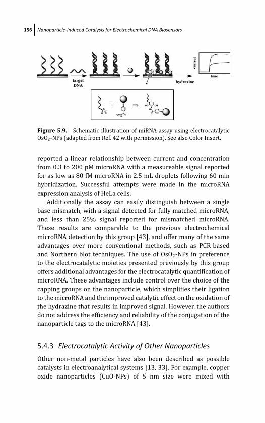
March 14, 2012 20:7 PSP Book - 9in x 6in 05-Ozsoz-c05
156 Nanoparticle-Induced Catalysis for Electrochemical DNA Biosensors
Figure 5.9. Schematic illustration of miRNA assay using electrocatalytic
OsO2-NPs (adapted from Ref. 42 with permission). See also Color Insert.
reported a linear relationship between current and concentration
from 0.3 to 200 pM microRNA with a measureable signal reported
for as low as 80 fM microRNA in 2.5 mL droplets following 60 min
hybridization. Successful attempts were made in the microRNA
expression analysis of HeLa cells.
Additionally the assay can easily distinguish between a single
base mismatch, with a signal detected for fully matched microRNA,
and less than 25% signal reported for mismatched microRNA.
These results are comparable to the previous electrochemical
microRNA detection by this group [43], and offer many of the same
advantages over more conventional methods, such as PCR-based
and Northern blot techniques. The use of OsO2-NPs in preference
to the electrocatalytic moieties presented previously by this group
offers additional advantages for the electrocatalytic quantification of
microRNA. These advantages include control over the choice of the
capping groups on the nanoparticle, which simplifies their ligation
to the microRNA and the improved catalytic effect on the oxidation of
the hydrazine that results in improved signal. However, the authors
do not address the efficiency and reliability of the conjugation of the
nanoparticle tags to the microRNA [43].
5.4.3 Electrocatalytic Activity of Other Nanoparticles
Other non-metal particles have also been described as possible
catalysts in electroanalytical systems [13, 33]. For example, copper
oxide nanoparticles (CuO-NPs) of 5 nm size were mixed with

March 14, 2012 20:7 PSP Book - 9in x 6in 05-Ozsoz-c05
Conclusions 157
graphite powder and used as catalysts for the electrochemical
detection of amikacin antibiotic oxidation, achieving a 40 times
higher current than with a bulk CuO-modified carbon paste
electrode [15]. Cu2O hollow spheres (150–220 nm sized spherical
aggregations of small Cu2O-NPs) were applied by Zhu et al. [44] in
electrochemical DNA sensing using a carbon paste electrode and
MB as the hybridization indicator. They make use of these particles
as enhancers to the ssDNA probe immobilization on the electrode
surface to obtain a sensitive detection of Hepatitis B virus DNA
sequences by differential pulse voltammetry.
More recently, Prussian blue nanoparticles (PB-NPs) were found
to catalyze the electrochemical reduction of H2O2 when immobilized
in the form of layers on ITO electrodes [14]. The application of
PB-NPs as catalytic labels for highly sensitive detection of DNA
hybridization was also reported based on their catalytic effect
toward H2O2 when embedded in polystyrene spheres and loaded
onto a gold-disk electrode [45].
Iron and iron oxide nanoparticles (Fe and Fe3O4-NPs)
also present catalytic properties in electroanalysis. Fe-NPs were
described as efficient and selective catalysts in the electrochemical
detection of H2O2 in the presence of O2 by facilitating the electron
transfer between adsorbates and the glassy carbon electrode
surface. Fe3O4-NPs were used to modify a crystalline gold electrode
for the electrochemical detection of dopamine. They showed good
catalytic activity by lowering the dopamine oxidation overpotential,
allowing the dopamine and ascorbic acid peaks to become separated
and resolvable and with even lower detection limits than the Au-NP
system referred above [13].
5.5 Conclusions
The induced catalysis by NPs is showing special interest in the DNA
biosensing technology. The application of NPs as catalysts in DNA
detection systems is related to the decrease of overpotentials of
the involved redox species including also the catalyzed reduction
of other metallic ions used in labeling-based hybridization sensing.
Although the most exploited materials in catalysis are the metals

March 14, 2012 20:7 PSP Book - 9in x 6in 05-Ozsoz-c05
158 Nanoparticle-Induced Catalysis for Electrochemical DNA Biosensors
from platinum group, with the introduction of nanotechnology
and the increasing interest for biosensing applications, gold nano-
particles, due to their facile conjugation with biological molecules,
besides other advantages, are being shown to be the most used.
Their applications as either electrocatalytic labels or modifiers
of DNA related transducers are bringing important advantages
in terms of sensitivity and detection limits in addition to other
advantages.
Ag-NPs are not so commonly used as Au-NPs but nevertheless
their catalytic properties in electrochemical detection have also
been exploited. For instance, they were reported as promoters for
electron transfer between the graphite electrode and hemoglobin
in a NO sensor system where they also act as a base to attach the
hemoglobin onto a pyrolytic graphite electrode while preserving
the hemoglobin natural conformation and therefore its reactivity
[46]. With respect to the application of silver catalytic properties
on DNA hybridization detection, the published works refer mostly
to its use in combination with Au-NPs by means of chemical or
electrochemical silver deposition onto them [29].
The catalytic properties of nanoparticles used in protein detec-
tion can also be extended to DNA analysis. For example, the
selective electrocatalytic reduction of silver ions onto the surface of
Au-NP reported by our group and applied for protein detection
can be extended to DNA analysis too [47]. The hydrogen catalysis
reaction induced by Au-NPs [48] and applied even for cancer cells
detection [20] is expected to bring advantages for DNA detection as
well.
The reported studies suggest that the use of nanoparticles as
catalysts in electroanalysis in general, and particularly in DNA
sensing is not confined to metal nanoparticles only. The conjugation
of nanoparticles with electrochemical sensing systems promises
large evolution in actual electroanalysis methods and is expected to
bring more advantages in DNA sensing overall in the development
of free PCR–DNA detection besides other applications that may
include microfluidics and lateral flow detection devices. These
works are under way at our and other laboratories. Their successful
application in DNA detection in real samples would require a
significant improvement of cost-efficiency of nanoparticle-based
March 14, 2012 20:7 PSP Book - 9in x 6in 05-Ozsoz-c05
References 159
detection systems, in general and those based on nanoparticle-
induced electrocatalysis, in particular.
Acknowledgments
We acknowledge funding from the MEC (Madrid) for the projects
MAT2008-03079/NAN, CSD2006-00012 “NANOBIOMED”
(Consolider-Ingenio 2010) the E.U.’s support under FP7 contract
number 246513 “NADINE” and the NATO Science for Peace and
Security Programme’s support under the project SfP 983807.
References
1. A. Merkoci, Biosensing using Nanomaterials, John Wiley & Sons,
Hoboken, New Jersey (2009).
2. A. Merkoci (ed.), Nanobiomaterials in electroanalysis, Electroanalysis19, 739–741 (2007).
3. A. Merkoci, Electrochemical biosensing with nanoparticles, FEBSJournal 274, 310–316 (2007).
4. A. de la Escosura-Muniz and A. Merkoci, Electrochemical detection of
proteins using nanoparticles: applications to diagnostics, Expert Opin.Med. Diagn. 4, 21–37 (2010).
5. A. T. Bell, The impact of nanoscience in heterogeneous catalysis, Science299, 1688–1691 (2003).
6. G. Ertl, H. Knozinger, and J. Weitkamp, Handbook of HeterogeneousCatalysis, Wiley-VCH, Weinheim (1997).
7. J. Das and H. Yang, Enhancement of electrocatalytic activity of DNA-
conjugated gold nanoparticles and its application to DNA detection,
J. Phys. Chem. C 113, 6093–6099 (2009).
8. T. G. Drummond, M. G. Hill, and J. K. Barton, Electrochemical DNA
sensors, Nature Biotechnol. 21, 1192–1199 (2003).
9. J. Liu, J. Liu, L. Yang, X. Chen, M. Zhang, F. Meng, T. Luo, and
M. Li, Nanomaterial assisted enhancement of hybridization for DNA
biosensors: a review, Sensors 9, 7343–7364 (2009).
10. R. Polsky, R. Gill, L. Kaganovsky, and I. Willner, Nucleic acid functional-
ized PtNPs: catalytic labels for the amplified electrochemical detection
of biomolecules, Anal. Chem. 78, 2268–2271 (2006).
March 14, 2012 20:7 PSP Book - 9in x 6in 05-Ozsoz-c05
160 Nanoparticle-Induced Catalysis for Electrochemical DNA Biosensors
11. T. Selvaraju, J. Das, K. Jo, K. Kwon, C. Huh, T. K. Kim, and H. Yang,
Nanocatalyst based assay using DNA-conjugated Au nanoparticles for
electrochemical DNA detection, Langmuir 24, 9883–9888 (2008).
12. D. Hernandez-Santos, M. B. Gonzalez-Garcıa, and A. Costa-Garcıa, Metal-
nanoparticles-based electroanalysis, Electroanalysis 14(18), 1225–
1235 (2002).
13. C. M. Welch and R. G. Compton. The use of nanoparticles in electroanaly-
sis: a review, Anal. Bioanal. Chem. 384, 601–619 (2006).
14. A. Wieckowski, E. R. Savinova, and C. G. Vayenas, Catalysis andElectrocatalysis at Nanoparticles Surfaces, Marcel Dekker, New York
(2003).
15. X. Luo, A. Morrin, A. J. Killard, and M. R. Smyth, Applications of nanopar-
ticles in electrochemical sensors and biosensors, Electroanalysis 18,
319–326 (2006).
16. A. Merkoci, M. Aldavert, S. Marın, and S. Alegret, New materials for
electrochemical sensing V: nanoparticles for DNA labelling, Trends Anal.Chem. 24, 341–349 (2005).
17. M. Pumera, M. T. Castaneda, M. I. Pividori, R. Eritja, A. Merkoci, and
S. Alegret, Magnetically triggered direct electrochemical detection of
DNA hybridization based Au67 Quantum Dot—DNA—paramagnetic
bead conjugate, Langmuir 21, 9625–9629 (2005).
18. A. de la Escosura-Muniz, A. Ambrosi, and A. Merkoci, Electrochemical
analysis with nanoparticle-based biosystems, Trends Anal. Chem. 27(7),
568–584 (2008).
19. A. Ambrosi, M. T. Castaneda, A. J. Killard, M. R. Smyth, S. Alegret, and
A. Merkoci, Double-codified gold nanolabels for enhanced immuno-
analysis, Anal. Chem. 79, 5232–5240 (2007).
20. A. de la Escosura-Muniz, C. Sanchez-Espinel, B. Dıaz-Freitas, A. Gonzalez-
Fernandez, M. Maltez-da Costa, and A. Merkoci, Rapid identification
of tumour cells using a novel electrocatalytic method based in gold
nanoparticles, Anal. Chem. 81, 10268–10274 (2009).
21. A. Merkoci, M. Aldavert, G. Tarrason, R. Eritja, and S. Alegret, Toward
an ICPMS-linked DNA assay based on gold nanoparticles immuno-
connected through peptide sequences, Anal. Chem. 77, 6500–6503
(2005).
22. A. Ambrosi, F. Airo, and A. Merkoci, Enhanced gold nanoparticle
based ELISA for breast cancer biomarker, Anal. Chem. 82, 1151–1156
(2010).
23. F. Wang and S. Hu. Electrochemical sensors based on metal semiconduc-
tor nanoparticles, Microchim. Acta. 165, 1–22 (2009).
March 14, 2012 20:7 PSP Book - 9in x 6in 05-Ozsoz-c05
References 161
24. J. Wang, R. Polsky, and D. Xu, Silver-enhanced colloidal electrochemical
stripping detection of DNA hybridization, Langmuir 17, 5739–5741
(2001).
25. H. Cai, Y. Wang, P. He, and Y. Fang, Electrochemical detection of DNA
hybridization based on silver-enhanced gold nanoparticle label, Anal.Chim. Acta. 469, 165–172 (2002).
26. T. Lee, H. Cai, and I. Hsing, Effects of gold nanoparticles and
electrode surface properties on electrocatalytic silver deposition for
electrochemical DNA hybridization detection, The Analyst 130, 364–
369 (2005).
27. Y. Li, J. T. Cox, and B. Zhang, Electrochemical responses and electrocataly-
sis at single Au nanoparticles, J. Am. Chem. Soc. 132, 3047–3054 (2010).
28. X. Xiao, S. Pan, J. S. Jang, F. Fan, and A. Bard, Single nanoparticle
Electrocatalysis: effect of monolayers on particle and electrode on
electron transfer, J. Phys. Chem. C. 113, 14978–14982 (2009).
29. J. Liu, L. Yang, X. Chen, M. Zhang, F. Meng, T. Luo, and M. Li, Nanomaterial-
assisted signal enhancement of hybridization for DNA biosensors: a
review, Sensors 9, 7343–7364 (2009).
30. T. You, O. Niwa, M. Tomita, and S. Hirono, Characterization of platinum
nanoparticle-embedded carbon film electrode and its detection of
hydrogen peroxide, Anal. Chem. 75, 2080–2085 (2003).
31. S. Wang and X. Lin. Electrodeposition of Pt-Fe(III) nanoparticle on glassy
carbon electrode for electrochemical nitric oxide sensor, Electrochim.Acta 50, 2887–2891 (2005).
32. N. Zhu, Z. Chang, P. He, and Y. Fang, Electrochemical DNA biosensors
based on platinium NPs combined carbon nanotubes, Anal. Chim. Acta545, 21–26 (2005).
33. F. W. Campbell and R. G. Compton, The use of nanoparticles in
electroanalysis: an updated review, Anal. Bioanal. Chem. 396, 241–259
(2010).
34. S. H. Lim, J. Wei, J. Lin, Q. Li, and J. K. You, A glucose biosensor
based on electrodeposition of Palladium nanoparticles and glucose
oxidase onto Nafion-solubilized carbon nanotube electrode, Biosens.Bioelectron. 2341–2346 (2005).
35. Y. Liu, J. Zhang, W. Hou, and J. J. Zhu, A Pd/SBA-15 composite: synthesis,
characterization and protein biosensing, Nanotechnology 19, 135707
(2008).
36. Z. Chang, H. Fan, K. Zhao, M. Chen, P. He, and Y. Fang. Electrochemical
DNA biosensors based on Palladium nanoparticles combined with
carbon nanotubes, Electroanalysis 20, 131–136 (2008).
March 14, 2012 20:7 PSP Book - 9in x 6in 05-Ozsoz-c05
162 Nanoparticle-Induced Catalysis for Electrochemical DNA Biosensors
37. J. Das, H. Kim, K. Jo, K. H. Park, S. Jon, K. Lee, and H. Yang, Fast catalytic
and electrocatalytic oxidation of sodium borohydride on palladium
nanoparticles and its application to ultrasensitive DNA detection, Chem.Comm. 6394–6395 (2009).
38. P. Lo, S. A. Kumar, and S. Chen, Amperometric determination of H2O2
at nano TiO2/DNA/thionin nanocomposite modified electrode, ColloidsInterf., B: Biointerfaces 66, 266–273 (2008).
39. H. Zhou, X. Gan, J. Wang, X. Zhu, and G. Li, Hemoglobin based hydrogen
peroxide biosensor tuned by the photovoltaic effect of nano titanium
dioxide, Anal. Chem. 77, 6102–6104 (2005).
40. W. Lu, Y. Jin, G. Wang, D. Chen, and J. H. Li, Enhanced photoelectro-
chemical method for linear DNA hybridization detection using Au-
nanoparticle labelled DNA as probe onto titanium dioxide electrode,
Biosens. Bioelectron. 23, 1534–1539 (2008).
41. Y. Hu, T. Yang, X. Wang, and K. Jiao, Highly sensitive indicator-
free impedance sensing of DNA hybridization based on poly (m-
aminobenzenosulfonic acid)/TiO2 nanosheetmembranes with pulse
potentiostatic method preparation, Chem. Eur. J. 16, 1992–1999 (2010).
42. Z. Gao and Z. Yang, Detection of microRNAs using electrocatalytic NPs
tags. Anal. Chem. 78, 1470–1477 (2006).
43. E. A. Hunt, A. M. Goulding, and S. K. Deo, Direct detection and
quantification of microRNAs, Anal. Biochem. 387, 1–12 (2009).
44. H. Zhu, J. Wang, and G. Xu, Fast synthesis of Cu2O hollow microspheres
and their application in DNA biosensor of Hepatitis B virus, CrystalGrowth and Design 9, 633–638 (2009).
45. S. Suwansa-ard, Y. Xiang, R. Bash, P. Thavarungkul, P. Kanatharana, and
J. Wang, Prussian Blue dispersed sphere catalytic labels for amplified
electronic detection of DNA, Electroanalysis 20, 308–312 (2008).
46. X. Gan, T. Liu, X. Zhu, and G. Li, An electrochemical biosensor for Nitric
Oxide based on silver nanoparticles and hemoglobin, Anal. Sciences 20,
1271–1275 (2004).
47. A. de la Escosura-Muniz, M. Maltez-da Costa, and A. Merkoci, Controlling
the electrochemical deposition of silver onto gold nanoparticles: reduc-
ing interferences and increasing the sensitivity of magnetoimmuno
assays, Biosen. Bioelectron. 24, 2475–2482 (2009).
48. M. Maltez-da Costa, A. de la Escosura-Muniz, and A. Merkoci,
Electrochemical quantification of gold nanoparticles based on their
catalytic properties on hydrogen formation: application in magneto
immunoassays, Electrochem. Commun. 12, 1501–1504 (2010).
March 14, 2012 20:8 PSP Book - 9in x 6in 06-Ozsoz-c06
Chapter 6
Application of Field-Effect Transistors toLabel-Free Electrical DNA BiosensorArrays
Peng Li,a Piero Migliorato,a and Pedro Estrelab
aDepartment of Engineering, University of Cambridge,Electrical Engineering Division, Cambridge CB3 0FA, United KingdombDepartment of Electronic & Electrical Engineering, University of Bath,Bath BA2 7AY, United [email protected]; [email protected]; [email protected]
Biotechnology is in great need of low-cost intelligent biochips
capable of massive parallel detection to be used in portable
instrumentation. One way this may be achieved is by exploiting
mature semiconductor technologies for the development of biosen-
sor arrays. We review here two highly promising techniques for
label-free electrical detection of DNA hybridization: potentiometric
detection and electrochemical impedance spectroscopy. Field-effect
transistor technologies can play an important role in the develop-
ment of these techniques in biosensor microarrays.
6.1 Introduction
The ability to detect biomolecular interactions is crucial in med-
ical, pharmaceutical, and biotechnological applications. The most
Electrochemical DNA BiosensorsEdited by Mehmet OzsozCopyright c© 2012 Pan Stanford Publishing Pte. Ltd.ISBN 978-981-4241-77-9 (Hardcover), 978-981-4303-98-9 (eBook)www.panstanford.com
March 14, 2012 20:8 PSP Book - 9in x 6in 06-Ozsoz-c06
164 Application of Field-Effect Transistors to Label-Free Electrical DNA Biosensor Arrays
commonly employed techniques for the detection of such inter-
actions are based on optical methods, in particular fluorescence
detection of labeled biomolecules. Large arrays of 500,000 spots
per chip are currently used for high-throughput screening of DNA
sequences, where a large volume of genomic data is obtained
with a single experiment. The parallel detection of biomolecular
interactions in large microarrays is of great scientific and economic
importance. Depending on the analyte, which can be DNA, proteins,
peptides, etc., applications of microarrays include gene expression
monitoring, pharmacogenomic research and drug discovery, clinical
diagnostics, including infectious and genetic diseases, cancer diag-
nostics, and viral and bacterial identification. It is also important for
the detection of biowarfare and bioterrorism agents, and for forensic
and genetic identification. To fully exploit these opportunities,
biosensors should provide a combination of high sensitivity and
selectivity, speed, low cost, and portability.
Although a large level of success has been achieved with
fluorescent-labeled DNA microarrays, these methods are difficult to
implement in portable instrumentation, so that their use is limited
to specialized laboratories. Electrical detection of biomolecular
interactions is highly desirable due to its suitability to low-
cost portable sensors that can be used in the field by non-
specialized personnel. The use of label-free techniques has the
added advantages of reducing costs and avoiding the need for
sample pre-treatment.
Over the past few decades, effort has been devoted to exploit
semiconductor field-effect transistors (FETs) in chemical and
biological sensors due to the potential of these devices to meet some
of the requirements discussed above. Most of this work concerned
the development of the ion-sensitive field-effect transistor (ISFET)
for the detection of specific ions and analytes using appropriate
ion-selective or enzymatic membranes. One of the advantages of
the ISFET is that it operates in equilibrium conditions. Due to the
presence of the insulating layer on top of the semiconductor, no
current flows across the biological layer.
More recently, field-effect devices have been investigated for
the detection of DNA hybridization and protein interactions. It is
expected that a full understanding of the mechanisms involved will
March 14, 2012 20:8 PSP Book - 9in x 6in 06-Ozsoz-c06
Field-Effect Transistors 165
result in optimal device designs and create a generic platform for the
detection of any biomolecular interactions that produce a change in
the charge distribution at the surface of a transistor gate.
Besides these potentiometric-based methods, a series of electro-
chemical techniques can be applied to the detection of biomolecular
interactions. Depending on the desired dynamic detection range and
the specific properties of the system under study, techniques such
as electrochemical impedance spectroscopy, voltage step capaci-
tance measurements, amperometry, differential pulse voltammetry,
square wave voltammetry, AC voltammetry, and chronopotentiomet-
ric stripping analysis can be used for label-free detection of DNA,
proteins, and peptides [1]. Often these techniques require the use of
redox mediators. Electrochemical impedance spectroscopy (EIS), in
particular, is a very promising technique for DNA biosensing [2, 3].
Of particular interest for FET-based chemical and biological
sensors is the use of thin-film transistors (TFTs). For example, the
polycrystalline silicon (poly-Si) TFT, which can provide the drive
logic as well as the switching transistors, is a very interesting
technology for the development of low cost, disposable biosensors,
with a large number of parallel channels. By employing poly-Si TFTs,
a microarray of over 105 channels, with integrated logic drivers,
would require only a few tens of electrical connections to the rest
of the system. These could be provided by edge connectors, thereby
enabling easy insertion and removal of the sensor array from the
external reading system and, therefore, single use of a complex
microarray. Furthermore, poly-Si TFTs with a special extended
gate structure have been used as potentiometric sensors for DNA
hybridization [4]. The construction of TFT-addressed biosensor
microarrays with integral scan and readout circuits constitutes, in
our opinion, one of the great future challenges for TFT-integrated
electronics.
6.2 Field-Effect Transistors
Potentiometric chemical and biological sensors detect the electric
potential which arises at the surface of a solid material when placed
in contact with an electrolyte. Field-effect semiconductor devices
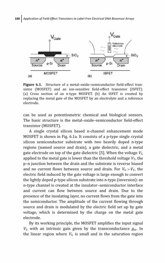
March 14, 2012 20:8 PSP Book - 9in x 6in 06-Ozsoz-c06
166 Application of Field-Effect Transistors to Label-Free Electrical DNA Biosensor Arrays
Figure 6.1. Structure of a metal–oxide–semiconductor field-effect tran-
sistor (MOSFET) and an ion-sensitive field-effect transistor (ISFET).
(a) Cross section of an n-type MOSFET. (b) An ISFET is created by
replacing the metal gate of the MOSFET by an electrolyte and a reference
electrode.
can be used as potentiometric chemical and biological sensors.
The basic structure is the metal–oxide–semiconductor field-effect
transistor (MOSFET).
A single crystal silicon based n-channel enhancement mode
MOSFET is shown in Fig. 6.1a. It consists of a p-type single crystal
silicon semiconductor substrate with two heavily doped n-type
regions (named source and drain), a gate dielectric, and a metal
gate electrode on top of the gate dielectric [5]. When the voltage VG
applied to the metal gate is lower than the threshold voltage VT, the
p–n junction between the drain and the substrate is reverse biased
and no current flows between source and drain. For VG >VT, the
electric field induced by the gate voltage is large enough to convert
the lightly doped p-type silicon substrate into n-type (inversion): an
n-type channel is created at the insulator–semiconductor interface
and current can flow between source and drain. Due to the
presence of the insulating layer, no current flows from the gate into
the semiconductor. The amplitude of the current flowing through
source and drain is modulated by the electric field set up by gate
voltage, which is determined by the charge on the metal gate
electrode.
By its working principle, the MOSFET amplifies the input signal
VG with an intrinsic gain given by the transconductance gm. In
the linear region where VG is small and in the saturation region
March 14, 2012 20:8 PSP Book - 9in x 6in 06-Ozsoz-c06
Field-Effect Transistors 167
where VG is sufficiently large, gm is given by the following equations,
respectively:
gm = ∂ ID
∂VG
∣∣∣∣
VD=const
= WL
μC VD (6.1)
gm = ∂ ID
∂VG
∣∣∣∣
VD=const
= WL
μC (VG − VT) (6.2)
where ID is the drain current, μ the carrier mobility of the substrate
material, C the gate capacitance per unit area, W and L the width
and length of the conducting channel, respectively. Hence the ampli-
fication power of a MOSFET device is closely related to the mobility
of the semiconductor material and can be tuned by the design of the
transistor. The sensitivity of the drain current to the charge on the
gate electrode can hence be explored for sensor applications.
If the metal gate of a MOSFET is removed from the field-effect
transistor and the gate dielectric placed in contact with a liquid
solution, as shown in Fig. 6.1b, ions can adsorb on the surface of the
gate dielectric, which generates an electric field similar to applying
a voltage at the metal gate [6, 7]. When an external gate voltage is
applied through a reference electrode in the solution, the electrical
field introduced by the adsorbed ions leads to a shift on the device
characteristic. As the shift is quantitatively linked to the type and
density of the adsorbed ions, this new device is hence named an ion-
sensitive field-effect transistor. Selectivity of ISFETs can be induced
by the appropriate incorporation of certain pH-sensitive insulators
or ion-selective membrane.
Successful application of ISFETs in pH meters has generated
great interest regarding the possibility of using the well-understood
FET technology to produce amplifying devices that would respond
to larger and more complex molecules in solution or gas phase,
such as DNA, enzymes, antibodies, or antigens, or even whole
tissue layers [4, 7–11]. Numerous biosensors have been developed
based on similar principles, with a large variety of targets, gate
materials, and device structures. More recently, FETs with a metal
gate functionalized with a biological recognition layer have also been
developed [4, 7, 11].
March 14, 2012 20:8 PSP Book - 9in x 6in 06-Ozsoz-c06
168 Application of Field-Effect Transistors to Label-Free Electrical DNA Biosensor Arrays
6.2.1 Field-Effect Transistor Technologies
One of the major advantages of employing FETs in sensor
applications is their mature manufacturing technology. Due to the
development of the microelectronics industry, the microfabrication
process has been well established allowing FETs to be mass-
produced with extremely high yield. Thin layers of materials can be
deposited on large areas of substrates and patterns of the device
can be created by lithography, through customized masks which
can be reused. The cost of each device is mainly determined by
the substrate area and production volume, making it possible to
fabricate complex sensor arrays at affordable costs. This is especially
attractive for biosensor applications, as disposability is a highly
emphasized feature to avoid contaminations.
6.2.1.1 Single crystalline silicon and CMOS
Traditional FET transistors are fabricated on a single crystalline
silicon wafer of a few hundred micrometer thickness. The silicon
crystalline framework is homogenous and continuous with very low
levels of defects. The electron mobility,μ, is therefore at a high level,
ranging from few hundreds to over a thousand cm2 V−1 s−1, enabling
high performance devices to be fabricated. In addition with the
abundance of material, cost-efficiency, and well-understood device
physics, single crystalline silicon has been the most widely used
substrate material in the microelectronics industry.
Complementary metal–oxide–semiconductor (CMOS) is a sin-
gle crystalline silicon-based semiconductor fabrication technology,
which distinguishes itself from other types of fabrication technolo-
gies by providing both n-type (as shown in Fig. 6.2a) and p-type
MOSFETs on the same substrate. It has been used predominantly in
microprocessors, memories, and other digital logic circuits due to
its low power consumption and unmatched production yield. CMOS
technology is also used for a wide variety of analog circuits such as
image sensors, data converters, and transceivers.
Driven by the microelectronics industry, the CMOS fabrication
process has been continuously refined to make smaller MOSFETs,
which are both faster and more cost-efficient. The state-of-the-art
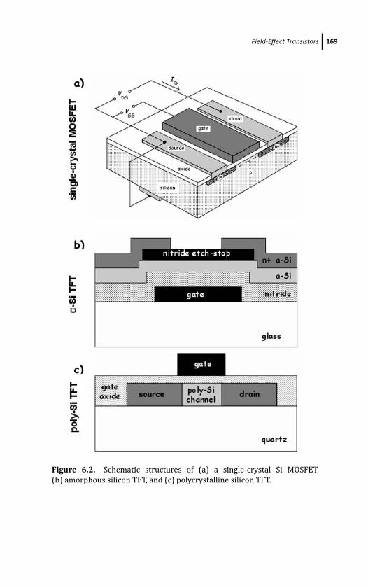
March 14, 2012 20:8 PSP Book - 9in x 6in 06-Ozsoz-c06
Field-Effect Transistors 169
Figure 6.2. Schematic structures of (a) a single-crystal Si MOSFET,
(b) amorphous silicon TFT, and (c) polycrystalline silicon TFT.
March 14, 2012 20:8 PSP Book - 9in x 6in 06-Ozsoz-c06
170 Application of Field-Effect Transistors to Label-Free Electrical DNA Biosensor Arrays
CMOS transistor today has gate dimensions as small as 45 nm and
working frequencies up to a few GHz. On the other hand, with the
high purity substrate material and advanced fabrication process,
the yield of the CMOS process is extremely high, making it possible
to include hundreds of millions of transistors in a single device.
Although the silicon MOSFET transistor does not have the best
noise and speed performance as other semiconductor devices in the
field of electronics, the well established CMOS technology certainly
makes it an obvious choice for biosensor applications.
Despite the high performance of CMOS, its manufacturing
process requires very high-cost equipment, clean room facilities,
and expensive high purity single-crystal silicon wafers. Those
limitations have set up the barrier to further reduce the fabrication
costs and hindered the use of CMOS technology in large area
electronics such as displays.
6.2.1.2 Thin-film transistors
Besides using a CMOS process, which employs single crystalline
silicon as a substrate, FETs can also be fabricated on thin films
of semiconductors such as amorphous (α-Si) or polycrystalline
silicon. A direct benefit of these technologies is to replace expensive
single crystalline silicon wafers with cheaper insulators supporting
a thin layer of deposited semiconductor as substrate, which
substantially reduces the manufacturing costs. A thin-film transistor
is a metal–insulator–semiconductor field-effect transistor (MISFET)
fabricated on an insulating substrate by employing entirely thin-
film constituents. The total thickness of the transistor is normally
less than 1 μm [12]. There are variations in TFT design, but the
basic device structures for both amorphous silicon and polycrys-
talline silicon technologies are depicted in Figs. 6.2b and 6.2c,
respectively.
Normally TFTs are operated like enhancement-mode MOSFETs. A
typical drain current ID vs. gate voltage VGS characteristic is shown
in Fig. 6.3. When the gate voltage VGS (with respect to the source) is
low, very little current flows between the source and drain, because
of the high resistance of the active layer. When the gate voltage is
high, charge is induced near the oxide–semiconductor interface, and
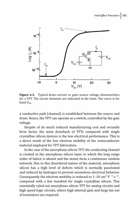
March 14, 2012 20:8 PSP Book - 9in x 6in 06-Ozsoz-c06
Field-Effect Transistors 171
Log
I D (
A)
Ion
IoffVGS
ID
VGS (V)
VDS
Figure 6.3. Typical drain current vs. gate–source voltage characteristics
for a TFT. The circuit elements are indicated in the inset. The curve is for
fixed VDS.
a conductive path (channel) is established between the source and
drain. Hence, the TFT can operate as a switch, controlled by the gate
voltage.
Despite of its much reduced manufacturing cost and versatile
form factor, the main drawback of TFTs compared with single
crystalline silicon devices is the low electrical performance. This is
a direct result of the low electron mobility of the semiconductor
material employed for TFT fabrication.
In the case of the amorphous silicon TFT, the conducting channel
is created in the amorphous silicon layer, in which the long range
order of lattice is absent and the atoms form a continuous random
network. Due to this disordered nature of the material, amorphous
silicon has a high level of defects which is normally passivated
and reduced by hydrogen to prevent anomalous electrical behavior.
Consequently the electron mobility is reduced to 1–10 cm2 V−1 s−1,
compared with a few hundred for single crystalline silicon. This
essentially ruled out amorphous silicon TFT for analog circuits and
high speed logic circuits, where high internal gain and large fan out
of transistors are required.

March 14, 2012 20:8 PSP Book - 9in x 6in 06-Ozsoz-c06
172 Application of Field-Effect Transistors to Label-Free Electrical DNA Biosensor Arrays
While amorphous silicon TFT suffers from low electronic
performance, it is very flexible in application and manufacturing.
One important advantage is that amorphous Si can be deposited
at temperatures as low as 75◦C. This makes it possible for the
device to be made not only on glass, but also on plastics. In
addition, amorphous silicon can be deposited over very large
areas by plasma-enhanced chemical vapor deposition (PECVD) with
standard industrial equipments. Both features make mass-scale
production of amorphous silicon TFT-based devices relatively easy
and economic. The main application for amorphous silicon TFT is
on liquid crystal displays (LCDs), in which each pixel is individually
driven by a TFT transistor.
Polycrystalline silicon is a material consisting of multiple small
silicon crystals with sizes ranging from nanometers to micrometers,
widely used as a gate material of FET and interconnection in
integrated circuits. Depending on the size of the crystals or
grains, the electron mobility in polycrystalline silicon lies between
that of amorphous and crystalline silicon, ranging from 10 to
100 cm2 V−1 s−1, and providing device performance good enough for
electronic circuits. It was the ability to fabricate integrated drive cir-
cuits [13] that stimulated the initial interest in polycrystalline silicon
for active matrix displays. The technology, now well developed, has
been for long time applied in LCD displays for projectors and is now
being used for mobile phones. Poly-Si TFTs have also been employed
to make static random-access memories (SRAMs) and operational
amplifiers.
The fabrication of a polycrystalline silicon film can be achieved
through various CVD methods or crystallization of amorphous
silicon. But these processes require high temperatures of at least
300◦C, making the deposition only possible on glass but not
plastic. A relatively new technique called laser recrystallization has
been devised to crystallize a precursor amorphous silicon film by
localized heating without damaging the plastic substrate. A transfer
process has also been developed to fabricate poly-Si TFT circuits on
plastic substrates [14].
In recent years, organic or polymer semiconductor materials
have been intensively researched to make TFTs. These organic
TFTs can be manufactured with very low cost using much simpler
March 14, 2012 20:8 PSP Book - 9in x 6in 06-Ozsoz-c06
Field-Effect Transistors 173
processes which don’t require clean room facilities, making it
suitable candidates for disposable biosensor applications. However,
as the development of those devices is still in its infancy and the
manufacturing processes have not been well established, organic
semiconductor TFTs will not be included further in this discussion.
6.2.2 Field-Effect Transistor Arrays
FETs are frequently employed on arrays in a variety of applications
like memories, displays, and sensor arrays such as charge-coupled
devices (CCDs). In these applications, FETs are used to construct cir-
cuit elements performing certain functions, which are then repeated
in a network. The nature of lithographic fabrication processes
makes FETs ideally suitable for large-scale array applications. Since
FETs are manufactured in batch mode with patterns transferred by
lithographic masks, the increased number of devices and complexity
only requires the alteration of the mask, while other manufacturing
steps essentially remain the same. Under mass production, the
fabrication cost of each array is hence determined by the area of
the substrate material consumed, and practically independent of
the number of array elements. Arrays integrating a large number
of elements require active logic addressing circuits to reduce the
number of interface connections. According to the requirements on
performance and cost, various types of FETs find their application in
different areas.
For high performance applications such as dynamic random
access memory (DRAM) and CCDs, where high density, high working
frequency, or high sensitivity is required, CMOS FETs are used for the
circuit elements. The peripheral circuits which address and read the
array cells are also built with CMOS and monolithically integrated
with the array elements to achieve high speed. Due to the relevant
high cost of CMOS process, these arrays are often highly integrated
with millions of array elements arranged on a substrate with an area
of about 1 cm2.
Liquid-crystal displays normally employ a matrix of amorphous
silicon TFTs to control the voltage applied to the individual
pixels. In order to drive an active-matrix addressed flat-panel
LCD, it is necessary to make contact to each of the row and
March 14, 2012 20:8 PSP Book - 9in x 6in 06-Ozsoz-c06
174 Application of Field-Effect Transistors to Label-Free Electrical DNA Biosensor Arrays
column connections, which typically amounts to over 2000 external
connections. However, the logic circuits driving the TFT matrix have
to be made by conventional single crystal silicon microchips, since α-
Si TFTs cannot provide logic drivers with the necessary speed, due
to the low electron mobility (<1 cm2 V−1 s−1).
Monolithic integration of logic drivers on the active matrix array
plate has the great advantage of reducing the number of electrical
connections between the array and the rest of the system, which
is of particular relevance when compact construction is a premium
to overcome space limitations. Polycrystalline silicon TFTs have a
much higher mobility (>100 cm2 V−1 s−1) than α-Si TFTs and
can therefore be used to provide the drive logic as well as the
pixel transistors. Complete integration reduces the total number of
external connections to ∼20 for power, clock, and input data signal
lines [15].
The above properties make poly-Si TFTs a very interesting
technology for the development of low-cost disposable biosensors,
with a large number of parallel channels. A microarray of 100,000
channels, with integrated logic drivers, would require only a few tens
of electrical connections to the rest of the system. These could be
provided by edge connectors thereby enabling easy insertion and
removal of the sensor array from the system and, therefore, single
use of a complex microarray.
6.3 Field-Effect DNA Sensing
Similarly to the working principle of ISFETs, the sensitivity of
FET devices to the charge on its gate electrode can be utilized to
develop sensors for the detection of charged biological species. In
general, biologically sensitive FETs (BioFETs) can be constructed
from MOSFET structures by functionalizing the gate electrode with
different biological recognition elements. A change in the charge
density of a biolayer immobilized on an electrode induces a change
in the electrode surface charge density, σ0, which in turn alters
the surface potential, ϕ0, that is, the open circuit potential (OCP).
A change in the surface potential may be generated by a catalytic
reaction product, surface polarization effects, or the change in dipole
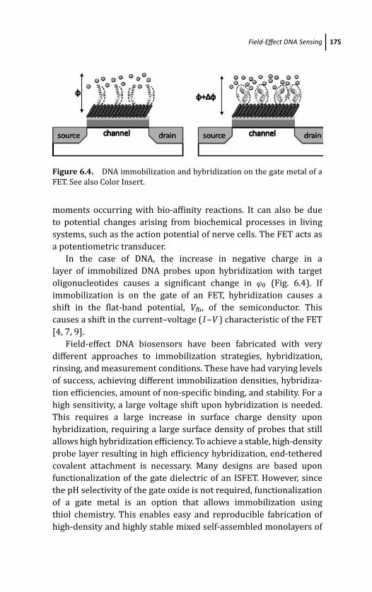
March 14, 2012 20:8 PSP Book - 9in x 6in 06-Ozsoz-c06
Field-Effect DNA Sensing 175
Figure 6.4. DNA immobilization and hybridization on the gate metal of a
FET. See also Color Insert.
moments occurring with bio-affinity reactions. It can also be due
to potential changes arising from biochemical processes in living
systems, such as the action potential of nerve cells. The FET acts as
a potentiometric transducer.
In the case of DNA, the increase in negative charge in a
layer of immobilized DNA probes upon hybridization with target
oligonucleotides causes a significant change in ϕ0 (Fig. 6.4). If
immobilization is on the gate of an FET, hybridization causes a
shift in the flat-band potential, Vfb, of the semiconductor. This
causes a shift in the current–voltage (I –V ) characteristic of the FET
[4, 7, 9].
Field-effect DNA biosensors have been fabricated with very
different approaches to immobilization strategies, hybridization,
rinsing, and measurement conditions. These have had varying levels
of success, achieving different immobilization densities, hybridiza-
tion efficiencies, amount of non-specific binding, and stability. For a
high sensitivity, a large voltage shift upon hybridization is needed.
This requires a large increase in surface charge density upon
hybridization, requiring a large surface density of probes that still
allows high hybridization efficiency. To achieve a stable, high-density
probe layer resulting in high efficiency hybridization, end-tethered
covalent attachment is necessary. Many designs are based upon
functionalization of the gate dielectric of an ISFET. However, since
the pH selectivity of the gate oxide is not required, functionalization
of a gate metal is an option that allows immobilization using
thiol chemistry. This enables easy and reproducible fabrication of
high-density and highly stable mixed self-assembled monolayers of
March 14, 2012 20:8 PSP Book - 9in x 6in 06-Ozsoz-c06
176 Application of Field-Effect Transistors to Label-Free Electrical DNA Biosensor Arrays
thiolated oligonucleotides, using only a single biochemical step.
It also eliminates various problems that may occur using semi-
conductor or insulator surfaces, which are prone to uncontrolled
modifications, contaminations, or hydration. These may lead to
a change in the intrinsic properties of the insulator, such as its
dielectric constant, which are critical for the stable operation of
FETs.
Polycrystalline silicon thin film transistors have also been
employed for the detection of DNA hybridization [16]. A mixed
self-assembled monolayer of thiolated DNA probes and mercapto-
hexanol was immobilized onto the gold gate of an extended gate
poly-Si TFT. A shift of the I –V characteristics on the order of 300 mV
was obtained upon hybridization of the immobilized probe with a
fully complementary strand. The shift is independent of electrode
area, so microarrays can be constructed where a known DNA probe
is immobilized on each FET. The inherent miniaturization and com-
patibility with microfabrication technologies make the technique
highly promising for the development of low-cost portable devices.
6.3.1 Physical Mechanisms of Detection
A better understanding of the physical mechanisms involved in the
field-effect detection of DNA is fundamental in the development
of reliable DNA microarrays based on FETs. Several aspects play a
role in the detection mechanism. Counterion condensation theory
can be used to evaluate the effective charge density of the DNA
layer in contact with an electrolyte, which partly screens its charge,
its dependence on the ionic strength of the electrolyte, and the
reduction of the charge fraction observed upon hybridization.
Mathematical models have been used to describe the observed shifts
in the I –V curves of the field-effect transistors.
The immobilization of the nucleic acid probe is crucial in deter-
mining the performance of the biosensor. To achieve high sensitivity
and selectivity, the hybridization efficiency must be maximized
and the non-specific adsorption minimized. Immobilization should
produce a stable layer of well-defined probe orientation, readily
accessible to the target. There are a wide variety of immobilization
methods, depending on the transducer surface and application. For
March 14, 2012 20:8 PSP Book - 9in x 6in 06-Ozsoz-c06
Field-Effect DNA Sensing 177
devices with a gold metal gate, mixed self-assembled monolayers of
thiols are usually chosen since they give rise to highly organized,
stable, and reproducible films in which the surface density of
the oligonucleotides can be controlled in order to eliminate
steric hinderance effects and increase the hybridization efficiency.
To achieve fast hybridization kinetics and a high hybridization
efficiency, a probe density of ≤3 × 1012 cm−2 is required [17]. To
obtain the greatest shift in gate potential (VG) in a field-effect sensor,
there will be a trade-off between greater hybridization efficiency
and greater counterion screening of the DNA charge as the probe
density is reduced. In addition, if the DNA layer is considered as a
plane charge, the voltage shift depends non-linearly upon the charge
density through the Grahame equation, so that an increase in the
density of probes may lead to a large increase in the charge density
upon hybridization, but only a small increase in the voltage shift.
Hybridization kinetics can be promoted with a high ionic
strength buffer, with specificity achieved by washing with a low ionic
strength buffer. A low ionic strength measurement buffer is required
for field-effect sensing to give little screening of charge. However,
the stability of the DNA duplex in these low ionic strengths must
be considered. To give greater hybridization efficiency and sequence
selectivity and to increase stability at low ionic strength, PNA probes
can be utilized.
6.3.1.1 Description of the electrochemical system
When an electrolyte is in contact with an electrode, an electrochem-
ical double layer forms. In the Gouy–Chapman–Stern model of the
electrochemical double layer [18], it is assumed that the solvent
provides a continuous dielectric medium with dielectric permittivity
equal to its bulk value, that charges of discrete ions are smeared out
into a continuous distribution of net charge density, and that ion–
ion interactions can be neglected so that all ions in solution are free
to contribute to the charge density. Due to their finite size, ions may
not approach the electrode closer than the outer Helmholtz plane
(OHP). Since there is no charge between the electrode and OHP,
the electric field E is constant in this region, and the electrostatic
potential ϕ varies linearly. Outside the OHP, the potential may be
March 14, 2012 20:8 PSP Book - 9in x 6in 06-Ozsoz-c06
178 Application of Field-Effect Transistors to Label-Free Electrical DNA Biosensor Arrays
determined by considering the solution to be divided into laminae
parallel to the electrode. The laminae are in thermal equilibrium, but
at differing energies due to the potential ϕ, so the concentration ni
of species i with valence zi is related to its bulk concentration n0i by
the Boltzmann factor
ni = n0i exp(−zieϕ/kT ) (6.3)
The net charge density ρ(x) is related to the potential by the
Poisson equation
ρ(x) = εε0
d2ϕ
dx2(6.4)
where ε is the relative dielectric permittivity, ε0 is the permittivity of
free space, and x is the distance from the electrode. Use of boundary
conditions leads to the non-linear Poisson–Boltzmann equation.
For ϕ � kT /e, the linearized Poisson–Boltzmann equation results.
Alternatively, the non-linear Poisson–Boltzmann equation may be
solved for a symmetrical electrolyte that contains only one cationic
and one anionic species, both with charge magnitude z, giving the
Grahame equation for the charge per unit area on the electrode σ1:
σ1 = −εε0
dϕ
dx
∣∣∣∣
OHP
=√
8kTεε0n0 sinh|z|eϕOHP
2kT(6.5)
6.3.1.2 DNA charge fraction
dsDNA is a semi-flexible chain with persistence length ∼100 nm,
where the persistence length is the distance in which tangent
vectors decorrelate, a measure of the rigidity of a polymer. Short
duplexes can be considered as cylinders of 2.0 nm diameter and
axial length per base pair of 0.34 nm. The corresponding parameters
for ssDNA have not been established. Stacking interactions between
hydrophobic bases tend to produce a stiff single-stranded helix and
ssDNA has been modeled as a cylinder of diameter ∼1.4 nm and axial
length per monomer of 0.34 nm [19]. However, if ssDNA is assumed
to be a freely jointed chain with a length per base of 0.43 nm [20],
its persistence length varies from 5 nm at 1 mM ionic strength to 0.8
nm at 100 mM ionic strength [21]. This is consistent with a much
stronger rigidity of dsDNA compared to ssDNA.
March 14, 2012 20:8 PSP Book - 9in x 6in 06-Ozsoz-c06
Field-Effect DNA Sensing 179
Manning’s counterion condensation (CC) theory [22] is the
asymptotic Poisson–Boltzmann solution for straight polyelec-
trolytes of infinite length at infinite separation and zero salt
concentration. If the axial charge spacing b is less than the Bjerrum
length lB (the distance at which two unit charges have a Coulomb
interaction energy equal to the thermal energy kT ), a fraction θ of
the polyelectrolyte charge is compensated by counterions localized
to the polyelectrolyte, reducing its net charge:
θ = 1 − ξ−1 (6.6)
where ξ is the Manning parameter, i.e., the number of unit charges
per Bjerrum length, given by
ξ = lB/b = e2/εε0kT b (6.7)
If b < lB, counterion condensation occurs and the net axial
charge density of the polyelectrolyte is reduced to one charge per
Bjerrum length (equal to 0.714 nm for water at 25◦C). CC remains
valid as long as the polyelectrolyte length is greater than the Debye
screening length λD and b � λD. At greater salt concentrations,
excessive counterion condensation is expected. CC holds for helical
charge lattices, with the counterion fraction still dependent upon the
axial charge spacing [23]. For dsDNA b = 0.17 nm, giving a charge
fraction of 24%. For ssDNA b ≈ 0.43 nm, giving a charge fraction
of 60%, and the same effective charge per unit length. Due to the
reduction in length upon duplex formation, dsDNA is expected to
have a lower net charge than ssDNA. This is valid as long as b � λD;
so counterion condensation is expected to remain valid at ionic
strengths much less than 500 mM, corresponding to a Debye length
of 0.43 nm. This charge fraction value of ∼25% for dsDNA has been
confirmed experimentally [24].
Molecular dynamics solutions have shown that as the separation
of polyelectrolytes is decreased from infinite, the counterion fraction
increases slightly from the Manning limit. At low salt concentrations,
CC is qualitatively unchanged. The layer of condensed counterions
contracts, but the amount of condensation is only marginally
increased. Increasing salt concentration leads to a crossover
between Manning condensation and charge screening when the
Debye length becomes smaller than the radius of the condensed
March 14, 2012 20:8 PSP Book - 9in x 6in 06-Ozsoz-c06
180 Application of Field-Effect Transistors to Label-Free Electrical DNA Biosensor Arrays
layer [25]. However, the Poisson–Boltzmann theory fails to describe
the physical situation if the electrostatic interactions are strong,
the counterions are multivalent or the density of DNA is high [26].
Monte Carlo studies of oligonucleotides have indicated that the local
cation concentration is expected to decrease sharply as either end
of the molecule is approached, due to coulombic end effects [27].
Due to end effects and dense packing of oligoelectrolytes, counterion
condensation may not give an accurate approximation of the charge
fraction for oligomers immobilized in a SAM. Molecular dynamics
studies of single-grafted ssDNA and dsDNA oligomers show that
counterion condensation increased with both longer chain lengths
and added salt [28]. For 16 bases oligonucleotides at zero salt
concentration, 30% of counterions were contained within 1.6 nm
of the oligonucleotide for dsDNA, compared to 15% for ssDNA.
Although dsDNA has a smaller charge fraction, its net charge will
be 65% greater than for ssDNA. Addition of 5 mM salt increased the
fraction of counterions within 1.6 nm of the ssDNA to 45%. Results
on salt addition were not given for dsDNA. In the single-chain limit
studied, a significant portion of counterions lies beyond the chain
length from the surface. However, for a strong polyelectrolyte brush,
counterions are expected to be contained within the brush with
electroneutrality satisfied locally [29].
The DNA charge will also be affected by its confinement to a SAM.
The ionization of acidic or basic groups in a SAM is less favored and
for acid groups pK a will increase by approximately 1 unit [30].
6.3.1.3 Quantitation of the field-effect device signal
A variety of different approaches to calculate the shift in the
I –V characteristics upon DNA hybridization or due to charge
redistribution upon antibody–antigen binding have been presented
in the literature. It has been suggested that the accumulation of
charged molecules at a surface might be electronically detected
as responses to a Donnan potential, which is built up during the
attachment of the molecules [31]. This should only be possible if the
sensor exhibits a pH sensitivity smaller than the Nerstian response.
If this is the case, the output signal should depend on the gate
material.
March 14, 2012 20:8 PSP Book - 9in x 6in 06-Ozsoz-c06
Field-Effect DNA Sensing 181
The relationship �VG = −�Q DNA/C ox, where Q DNA is the
charge of the DNA SAM and C ox is the gate insulator capacitance
has been proposed in the literature [32]. This relationship is of
the same form as that of a shift in flat-band potential due to a
fixed oxide charge Q f located at the Si–SiO2 interface in a MOSFET.
However, the DNA charge is instead located at the metal–solution or
insulator–solution interface. Therefore, to return the semiconductor
to the state it would be in the absence of the DNA charge requires
charging the double-layer capacitance. Approximating the double-
layer capacitance as constant, the relationship should be �VG =−�Q DNA/C dl.
Other authors equate �VG to the change in electrochemical
double-layer surface potential resulting from the change in surface
charge, calculated using the Grahame equation [33]. The solution
and semiconductor are coupled by the electric field in the oxide,
ESiO2. If VG is adjusted to operate the FET at constant current, ESiO2
and the potential drop across the semiconductor and oxide remain
constant, and the only changes in the system occur in the double
layer. Therefore, �VG is equal to the change in potential across
the double layer, and no consideration of semiconductor physics is
necessary [7].
If the biomolecular probe is immobilized onto a metal electrode,
such as the metal gate of a MOSFET, a contact can be made to this
electrode and the open-circuit potential EOC measured against the
reference electrode. Since VG = ϕsolid state − EOC, where ϕsolid state is
the constant potential difference between the FET source and the
solid–solution interface, EOC corresponds to the shift of the I –Vcharacteristics from those measured by direct connection between
the gate and source or back contact. Therefore, the FET is simply
being used to measure the change in open-circuit potential, taking
advantage of its high-input impedance, low-output impedance, and
small size.
A one-dimensional model for electrolyte–insulator–metal–
oxide–semiconductor and electrolyte–insulator–semiconductor
structures modified with a charged membrane has been presented
[34]. It was shown that the largest sensitivity occurs at low
electrolyte concentrations, and that the signal from hybridization
is expected to be smaller than that from probe immobilization,
March 14, 2012 20:8 PSP Book - 9in x 6in 06-Ozsoz-c06
182 Application of Field-Effect Transistors to Label-Free Electrical DNA Biosensor Arrays
assuming a doubling of the membrane charge density. Proto-
nation/deprotonation of surface sites significantly reduces the
magnitude of the variation of the surface potential with respect
to the bulk electrolyte by effectively pinning the insulator surface
potential. At 10 mM salt concentration, the difference in potential
upon hybridization saturates with increasing probe density, so
increasing the probe density above 1 × 1012 cm−2 is not expected
to further increase the shift upon hybridization. At these high probe
densities, a −19 mV shift is calculated for full hybridization on an
uncharged surface, 6 times greater than the −3 mV change with
an amphoteric Al2O3 surface. At salt concentrations of 10 mM or
greater, where the thickness of the charged layer is significantly
greater than the Debye length, for uncharged surfaces the Donnan
potential was shown to give a good approximation of the double-
layer potential.
Finite element modeling of DNA functionalized electrodes was
applied to calculate the interfacial potential, and used to identify
conditions for maximum potential change with target hybridization
[35]. Using different models such as the Donnan potential model
[34] and numerical solution of the Poisson–Boltzmann equation
for a three-dimensional model, the authors estimate a maximum
potential variation of −17 mV for 100% hybridization efficiency at
the optimized DNA probe density of 3 × 1012 cm−2 even at low ionic
strength.
Even though larger shifts have been reported in the literature,
the simulations give a good insight on the variation of the signal
with probe density and ionic strength. The signal decreases rapidly
at probe densities lower than 1 × 1012 cm−2, while increasing the
probe density above the optimal value has little effect due to the
reduction of hybridization efficiency. Decreasing the ionic strength
on the other hand, has little effect on the signal at high probe
densities but increases the signal at low probe densities.
The value of the interfacial potential with ssDNA is significantly
larger than the change in potential resulting from hybridization.
In addition, decreasing the ionic strength significantly increases
the potential but not the variation in potential upon hybridization.
If uncharged PNA probes are used instead of DNA probes, the
interfacial potential before hybridization is expected to be approx-
imately zero, independent of ionic strength. Therefore, significantly
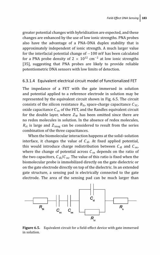
March 14, 2012 20:8 PSP Book - 9in x 6in 06-Ozsoz-c06
Field-Effect DNA Sensing 183
greater potential changes with hybridization are expected, and these
changes are enhanced by the use of low ionic strengths. PNA probes
also have the advantage of a PNA–DNA duplex stability that is
approximately independent of ionic strength. A much larger value
for the interfacial potential change of −100 mV has been calculated
for a PNA probe density of 2 × 1012 cm−2 at low ionic strengths
[35], suggesting that PNA probes are likely to provide reliable
potentiometric DNA sensors with low limits of detection.
6.3.1.4 Equivalent electrical circuit model of functionalized FET
The impedance of a FET with the gate immersed in solution
and potential applied to a reference electrode in solution may be
represented by the equivalent circuit shown in Fig. 6.5. The circuit
consists of the silicon resistance RSi, space-charge capacitance C SC,
oxide capacitance C ox of the FET, and the Randles equivalent circuit
for the double layer, where Z W has been omitted since there are
no redox molecules in solution. In the absence of redox molecules,
Rct is large and Z imag can be considered to result from the series
combination of the three capacitances.
When the biomolecular interaction happens at the solid–solution
interface, it changes the value of C dl. At fixed applied potential,
this would introduce charge redistribution between C dl and C ox,
where the change of potential across C ox depends on the ratio of
the two capacitors, C dl/C ox. The value of this ratio is fixed when the
biomolecular probe is immobilized directly on the gate dielectric or
on the gate electrode directly on top of the dielectric. In an extended
gate structure, a sensing pad is electrically connected to the gate
electrode. The area of the sensing pad can be much larger than
Figure 6.5. Equivalent circuit for a field-effect device with gate immersed
in solution.
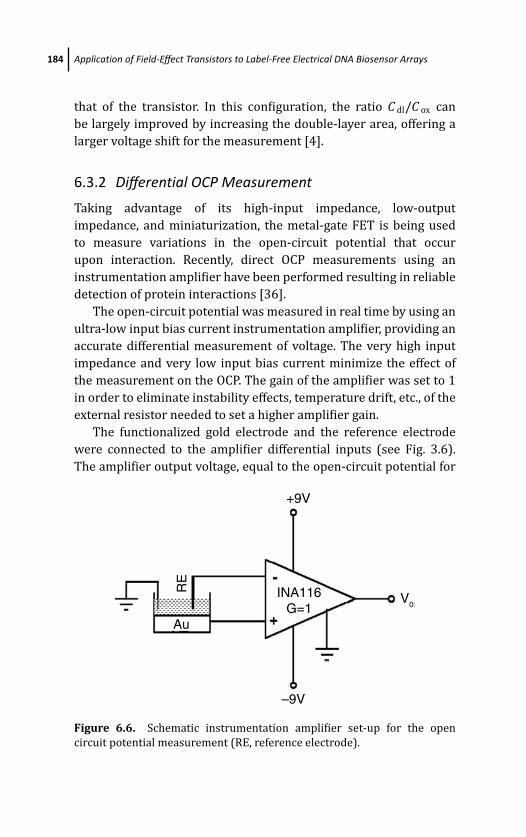
March 14, 2012 20:8 PSP Book - 9in x 6in 06-Ozsoz-c06
184 Application of Field-Effect Transistors to Label-Free Electrical DNA Biosensor Arrays
that of the transistor. In this configuration, the ratio C dl/C ox can
be largely improved by increasing the double-layer area, offering a
larger voltage shift for the measurement [4].
6.3.2 Differential OCP Measurement
Taking advantage of its high-input impedance, low-output
impedance, and miniaturization, the metal-gate FET is being used
to measure variations in the open-circuit potential that occur
upon interaction. Recently, direct OCP measurements using an
instrumentation amplifier have been performed resulting in reliable
detection of protein interactions [36].
The open-circuit potential was measured in real time by using an
ultra-low input bias current instrumentation amplifier, providing an
accurate differential measurement of voltage. The very high input
impedance and very low input bias current minimize the effect of
the measurement on the OCP. The gain of the amplifier was set to 1
in order to eliminate instability effects, temperature drift, etc., of the
external resistor needed to set a higher amplifier gain.
The functionalized gold electrode and the reference electrode
were connected to the amplifier differential inputs (see Fig. 3.6).
The amplifier output voltage, equal to the open-circuit potential for
V0INA116
G=1
RE
Au
–9V
+9V
Figure 6.6. Schematic instrumentation amplifier set-up for the open
circuit potential measurement (RE, reference electrode).
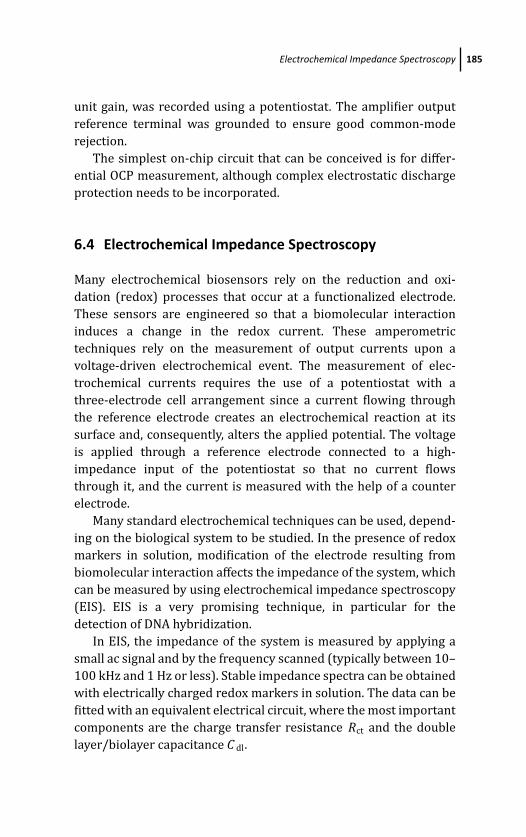
March 14, 2012 20:8 PSP Book - 9in x 6in 06-Ozsoz-c06
Electrochemical Impedance Spectroscopy 185
unit gain, was recorded using a potentiostat. The amplifier output
reference terminal was grounded to ensure good common-mode
rejection.
The simplest on-chip circuit that can be conceived is for differ-
ential OCP measurement, although complex electrostatic discharge
protection needs to be incorporated.
6.4 Electrochemical Impedance Spectroscopy
Many electrochemical biosensors rely on the reduction and oxi-
dation (redox) processes that occur at a functionalized electrode.
These sensors are engineered so that a biomolecular interaction
induces a change in the redox current. These amperometric
techniques rely on the measurement of output currents upon a
voltage-driven electrochemical event. The measurement of elec-
trochemical currents requires the use of a potentiostat with a
three-electrode cell arrangement since a current flowing through
the reference electrode creates an electrochemical reaction at its
surface and, consequently, alters the applied potential. The voltage
is applied through a reference electrode connected to a high-
impedance input of the potentiostat so that no current flows
through it, and the current is measured with the help of a counter
electrode.
Many standard electrochemical techniques can be used, depend-
ing on the biological system to be studied. In the presence of redox
markers in solution, modification of the electrode resulting from
biomolecular interaction affects the impedance of the system, which
can be measured by using electrochemical impedance spectroscopy
(EIS). EIS is a very promising technique, in particular for the
detection of DNA hybridization.
In EIS, the impedance of the system is measured by applying a
small ac signal and by the frequency scanned (typically between 10–
100 kHz and 1 Hz or less). Stable impedance spectra can be obtained
with electrically charged redox markers in solution. The data can be
fitted with an equivalent electrical circuit, where the most important
components are the charge transfer resistance Rct and the double
layer/biolayer capacitance C dl.
March 14, 2012 20:8 PSP Book - 9in x 6in 06-Ozsoz-c06
186 Application of Field-Effect Transistors to Label-Free Electrical DNA Biosensor Arrays
The charge of a biolayer immobilized onto an electrode will
create an electrostatic barrier to, e.g., the negatively charged
[Fe(CN)6]3−/4− redox couple in solution, which is reflected in the
value of the charge transfer resistance. Upon interaction, the charge
distribution of the biolayer will change, causing a modification in the
electrostatic barrier and, therefore, in the value of Rct. An increase in
Rct can be related to an increase in negative charge or a decrease in
positive charge at the biolayer. Reverse charge changes will cause a
decrease in Rct. Another important factor to take into account when
interpreting charge-transfer resistance changes is the fact that some
areas on the Au surface which are accessible to the redox couple, will
be blocked upon the biomolecular interaction due to the relatively
large volumes of target molecules, such as proteins. This effect will
result in an increased Rct.
On the other hand, a change in capacitance is expected upon
biomolecular interactions. When a large target biomolecule inter-
acts with the immobilized probe, the biolayer thickness increases,
causing a decrease in the total capacitance of the system.
In the case of DNA, hybridization at the electrode results in
a significant increase in the negative charge of the DNA layer.
Therefore, the electrostatic barrier to the negatively charged redox
couple becomes stronger upon hybridization, causing an increase
in the charge transfer resistance. A typical Nyquist plot (−Z imag vs.
Z real) is shown in Fig. 6.7 for a Au electrode after immobilization
of single-stranded DNA probe and after hybridization with its
complementary strand. The charge transfer resistance corresponds
to the diameter of the semi-circle in the Nyquist plot. For the sample
in Fig. 6.7, a 5 k� increase in Rct is observed upon hybridization [37].
The technique is robust and large signal discrimination upon
hybridization can be obtained with optimization of the DNA
probe density and the measurement conditions. Keighley et al.[37] report on the optimization of co-immobilization of thio-
lated oligonucleotides and mercaptohexanol to form mixed self-
assembled monolayers on gold. Specifying the solution mole ratio of
the thiol components provides an effective and easily implemented
method to accurately control the oligonucleotide surface density.
A linear relationship between mole ratio and probe density was
observed for the range (1.3–9.1) × 1012 probes/cm2. With this
March 14, 2012 20:8 PSP Book - 9in x 6in 06-Ozsoz-c06
Electrochemical Impedance Spectroscopy 187
Figure 6.7. Electrochemical impedance spectroscopy characteristics for a
Au electrode with ssDNA and after hybridization.
method the sample-to-sample variability was reduced as compared
to previously reported immobilization methods. The ratio on the
surface was approximately equal to that in the solution only for DNA
mole fractions lower than 0.3%.
Electrostatic repulsion between the immobilized negatively
charged oligonucleotide probes and negatively charged ferri/
ferrocyanide redox couple in solution results in a modulation of the
charge transfer resistance with probe surface density. The increase
in negative charge at the sensor surface upon hybridization only
results in a modulation of charge transfer resistance at probe
densities above 2.5 × 1012 cm−2 [37]. This threshold is probably due
to counterion screening of the oligonucleotide charge resulting in
channels between probes through which the mass transport of the
ferri/ferrocyanide redox couple is unaffected.
March 14, 2012 20:8 PSP Book - 9in x 6in 06-Ozsoz-c06
188 Application of Field-Effect Transistors to Label-Free Electrical DNA Biosensor Arrays
The maximum percentage change of charge transfer resistance
upon hybridization with fully complementary target oligonu-
cleotides was obtained with samples prepared by co-immobilization
of oligonucleotide probes and mercaptohexanol with a DNA mole
fraction of 20%. This corresponds to a mean probe surface density
of 5.4 × 1012 cm−2.
6.4.1 PNA-Based Sensing
The electrostatic barrier to the negatively charged redox markers
changes upon DNA hybridization, causing the EIS signal. The use
of PNA probes yields much larger EIS signals upon hybridization.
Since PNA is uncharged, the potential barrier before hybridization
is negligible resulting in a very low charge transfer resistance value;
upon hybridization with the charged DNA target, the potential
barrier is strongly felt resulting in a particularly large variation of
Rct.
Optimization of PNA surface density resulted in a massive
enhancement of the fractional change in Rct upon hybridization,
without the use of additional biochemical amplification steps [38].
A fractional change 100-fold larger than previously reported has
been achieved. Another relevant aspect is that the optimization
of PNA surface density in a mixed PNA/MCH SAM results in a
small initial Rct, controlled by the mercaptohexanol regions of
the SAM. For a given electrode area and overpotential, a smaller
Rct gives a greater current density. For a given sensitivity of the
detection electronics, higher current densities enable a reduction
of the minimum sensing electrode area and therefore an improved
detection limit. A detection limit of 25 fmol target was demonstrated
by Keighley et al. [38]. This is likely to be further improved by
reduction of the electrode area and sample volume. For example,
reducing the electrode diameter from 2 mm to 100 μm, a 400-fold
decrease in area, would increase the initial Rct to around 4 M�. A
10 mV AC overpotential would result in an approximately 2.5 nA
AC current, feasibly measured in a portable detection system. This
would allow the sample volume to be scaled to 3 nl, reducing the
detection limit to 3 amol. This shows electrochemical impedance
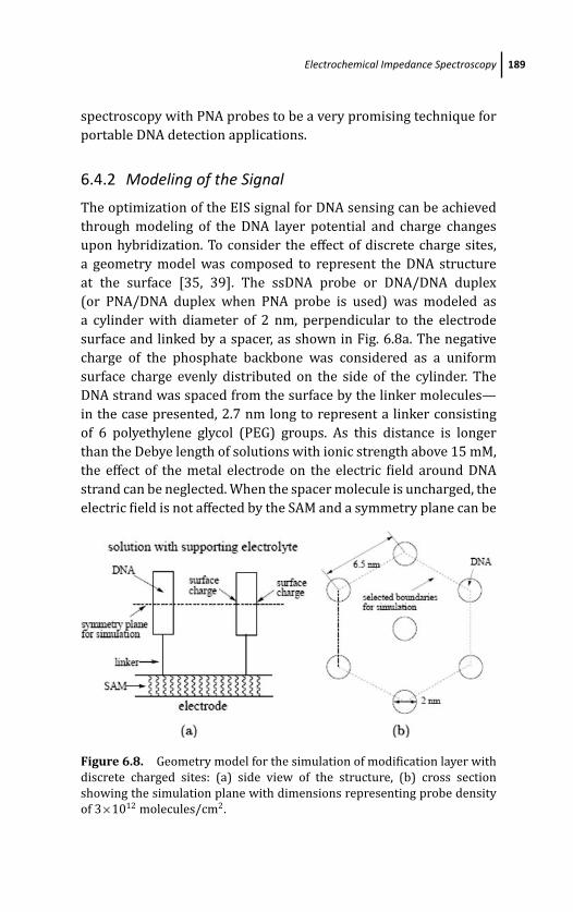
March 14, 2012 20:8 PSP Book - 9in x 6in 06-Ozsoz-c06
Electrochemical Impedance Spectroscopy 189
spectroscopy with PNA probes to be a very promising technique for
portable DNA detection applications.
6.4.2 Modeling of the Signal
The optimization of the EIS signal for DNA sensing can be achieved
through modeling of the DNA layer potential and charge changes
upon hybridization. To consider the effect of discrete charge sites,
a geometry model was composed to represent the DNA structure
at the surface [35, 39]. The ssDNA probe or DNA/DNA duplex
(or PNA/DNA duplex when PNA probe is used) was modeled as
a cylinder with diameter of 2 nm, perpendicular to the electrode
surface and linked by a spacer, as shown in Fig. 6.8a. The negative
charge of the phosphate backbone was considered as a uniform
surface charge evenly distributed on the side of the cylinder. The
DNA strand was spaced from the surface by the linker molecules—
in the case presented, 2.7 nm long to represent a linker consisting
of 6 polyethylene glycol (PEG) groups. As this distance is longer
than the Debye length of solutions with ionic strength above 15 mM,
the effect of the metal electrode on the electric field around DNA
strand can be neglected. When the spacer molecule is uncharged, the
electric field is not affected by the SAM and a symmetry plane can be
Figure 6.8. Geometry model for the simulation of modification layer with
discrete charged sites: (a) side view of the structure, (b) cross section
showing the simulation plane with dimensions representing probe density
of 3×10¹² molecules/cm2.
March 14, 2012 20:8 PSP Book - 9in x 6in 06-Ozsoz-c06
190 Application of Field-Effect Transistors to Label-Free Electrical DNA Biosensor Arrays
found at half of the height of the DNA probe, as shown with the dash
line in Fig. 6.8a. Since the length of ssDNA probe is normally much
longer than that of its width, as an approximation the model can be
simplified into a two-dimensional simulation on this plane. Since
the top and bottom sides of the cylinder do not carry any charge
in the model, the electric field on the simulation plane is hence the
largest potential which determines the charge transfer resistance.
Figure 6.8b shows the view on the symmetry plane for simulation.
The probe was assumed to be arranged in a homogeneous hexagonal
lattice with a center-to-center spacing determined by the probe
density.
Similar to that of a uniformly charged layer, the Poisson–
Boltzmann equation was solved numerically in two dimensions
within the domain surrounded by the dash line in Fig. 6.8b. A
typical result with a probe density of 3×10 12 molecules/cm2 and
measurement ionic strength of 50 mM is shown in Fig. 6.9 [39]. Upon
bonding of DNA target, the increase of the charge density further
enhances the electric field around the hybridization site, resulting
in a change of Rct, which can be measured as the sensing signal of
target hybridization.
Detection of DNA target can also be achieved with ssPNA as the
probe. Using DNA or PNA as sensing probe presents two different
situations for the change of charge upon the hybridization. For DNA
probe, the ssDNA itself carries charge before the target binding
and the target hybridization increases the surface charge. While for
a PNA probe, target binding converts an uncharged surface to a
charged surface. The signal range of the sensor is defined by the
signal measured with the probe fully hybridized by the target and
the signal of the un-hybridized probe.
From simulation results, using PNA probe yields larger signal
range for all probe densities [39]. The difference is more pronounced
with high probe densities, when the hybridization signal with PNA
probe can be over 10 times larger than that of DNA probe measured
with the designated ionic strength.
As shown in Fig. 6.9, the electric field generated by the
charged probes extends laterally, until screened by the supporting
electrolyte. From the Debye theory, the screening length is also
a function of the ionic strength. For the same modified surface,

March 14, 2012 20:8 PSP Book - 9in x 6in 06-Ozsoz-c06
Electrochemical Impedance Spectroscopy 191
Surface: Electric potential Contour: Electric potential
–6 –4 –2 0 2 4 6
× 10–9
6
4
2
0
–2
–4
–6
× 10–9
Min: –0.124 Min: –0.117
–0.02
–0.03
–0.04
–0.05
–0.06
–0.07
–0.08
–0.09
–0.1
–0.11
–0.12
Max: –0.0195 Max: –0.022
–0.027
–0.032
–0.037
–0.042
–0.047
–0.052
–0.057
–0.062
–0.067
–0.072
–0.077
–0.082
–0.087
–0.092
–0.097
–0.102
–0.107
–0.112
–0.117
Figure 6.9. Simulated electric potential produced by DNA probe immo-
bilized with the mixed SAM structure with an uncharged spacer. The DNA
probe density is set to be 3×10¹² molecules/ cm2 and ionic strength 50 mM.
decreasing the ionic strength of the measurement solution can result
in a larger and more extended potential field, which leads to a larger
impedance signal.
The signal, defined as the ratio Rct(duplex)/Rct(probe), is
estimated to have very different ranges for the situation where DNA
or PNA are used as probes: with PNA the signal increases drastically
upon hybridization from 1.1 to 2 × 10⁶ when the ionic strength is
reduced from 1000 to 1 mM; under the same conditions, using a DNA
probe only yields an increase from 1.05 to 3.5. The signal range using
DNA probe saturates when the ionic strength is lower than 10 mM,
since Rct of both ssDNA and dsDNA increases with similar amplitude.
For the PNA probe, as the probe itself is not charged, decrease of
ionic strength always gives increased signal range. When the ionic
strength is sufficiently low (∼50 mM for the probe density studied),
March 14, 2012 20:8 PSP Book - 9in x 6in 06-Ozsoz-c06
192 Application of Field-Effect Transistors to Label-Free Electrical DNA Biosensor Arrays
a linear relationship is observed between the signal range and ionic
strength on the log scale. These results further support that PNA is
better as sensor probe than DNA for EIS hybridization detection.
6.5 Application of FETs on Biosensor Arrays
Application of biosensors in areas such as pathogen identification
and gene expression requires a large number of sensor elements
to work simultaneously in an array format. As an example, current
fluorescence-based optical DNA microarrays for genotyping and
gene expression often involve ∼500,000 spots, where an individual
probe is deposited at each sensor element [40, 41]. High level of
integration and performance is clearly required in those devices.
The development of optical biosensor arrays is limited by the optical
scanner’s high cost, the unreliability of the optical labeling process,
and the complex data processing procedures. Considerable efforts
have been devoted to the development of alternative biosensor
array platforms suitable for low-cost production and higher level of
integration.
Fully integrated label-free electronic biosensor arrays based on
well-established microfabrication methods are believed to be able
to adequately address the disadvantages of optical arrays. Label-free
electrochemical characterization techniques can be implemented
directly using integrated electronics, achieving significant cost
reduction and better system integration. These electronic biosensor
arrays can be easily connected to simple handheld readers for point-
of-care applications. Moreover, studies have shown that electrical
stimulation can significantly affect the kinetics of biomolecular
interaction at solid–liquid interface [42–44], which is easily achieved
with electronic biosensor arrays.
6.5.1 FET-Addressed Biosensor Arrays
Besides the biomolecular probes and the packaging components, the
electronic components of a fully integrated biosensor array can be
divided into three categories: transducer, array addressing circuit,
and measurement unit. As the most widely used microelectronic
devices, FETs play an important role in all these three categories.
March 14, 2012 20:8 PSP Book - 9in x 6in 06-Ozsoz-c06
Application of FETs on Biosensor Arrays 193
As previously introduced, the FET itself can be used as a
potentiometric biosensor transducer to translate biomolecular
interactions into variations of flat-band voltage or source–drain
current. The ability of miniaturization makes FETs ideal candidates
for applications on biosensing arrays, as the signal-to-noise ratio
is independent of the geometry size. This feature allows FET-
based biosensors to be integrated on extremely high-density arrays,
with the limit of detection determined by the immobilization of
biomolecular probes and practical operations. The performance of
an FET-based potentiometric transducer depends on the internal
gain of the FET, which is measured by the transconductance, and on
the fabrication geometry, which determines the ratio of the double
layer capacitance to the gate dielectric capacitance.
Independently of the electrochemical technique employed for
DNA sensing, FETs can have an important role in the development
of electronically addressed biosensor arrays. Acting as switches for
individual cell elements, there are two basic requirements for the
addressing circuits. First, the electronic switch attached to each
sensor must have a high on/off current ratio. This is to make sure
that when the designated sensor element is measured, interference
from other sensor elements does not affect the characterization.
The second requirement is that the logic circuit, which translates
the input signal into the address information and selects the sensor
element, must work at a high enough frequency. As the biomolecular
reaction is often a dynamic process when the measurement is
carried out, all the sensor elements need to be characterized in a
relatively short time window, typically a few seconds. The driver
logic circuit needs to switch on all the sensor elements sequentially
within this time window to allow the measurements.
Two possible architectures for TFT-addressed biosensor arrays
are illustrated in Figs. 6.10 and 6.11. For potentiometric sensing,
the biosensing pad is connected to the gate of the TFT (see
Fig. 6.10), which acts as the transducer. A dummy transistor, where
no biomolecular interaction occurs, can be used for differential
measurements [45]. For current detection, the sensing pad needs
to be connected to the source or the drain of the TFT as shown in
Fig. 6.11.
As the biomolecular interaction delivers a very weak electronic
signal, integrated amplification and noise canceling are often
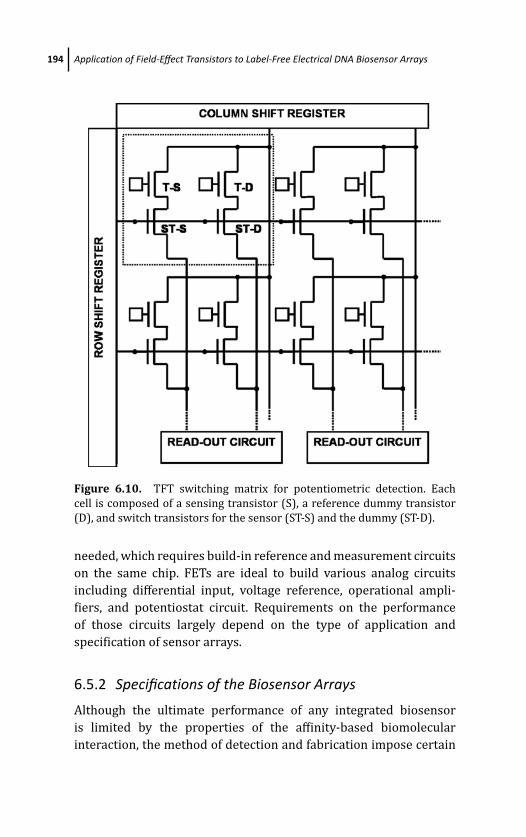
March 14, 2012 20:8 PSP Book - 9in x 6in 06-Ozsoz-c06
194 Application of Field-Effect Transistors to Label-Free Electrical DNA Biosensor Arrays
Figure 6.10. TFT switching matrix for potentiometric detection. Each
cell is composed of a sensing transistor (S), a reference dummy transistor
(D), and switch transistors for the sensor (ST-S) and the dummy (ST-D).
needed, which requires build-in reference and measurement circuits
on the same chip. FETs are ideal to build various analog circuits
including differential input, voltage reference, operational ampli-
fiers, and potentiostat circuit. Requirements on the performance
of those circuits largely depend on the type of application and
specification of sensor arrays.
6.5.2 Specifications of the Biosensor Arrays
Although the ultimate performance of any integrated biosensor
is limited by the properties of the affinity-based biomolecular
interaction, the method of detection and fabrication impose certain
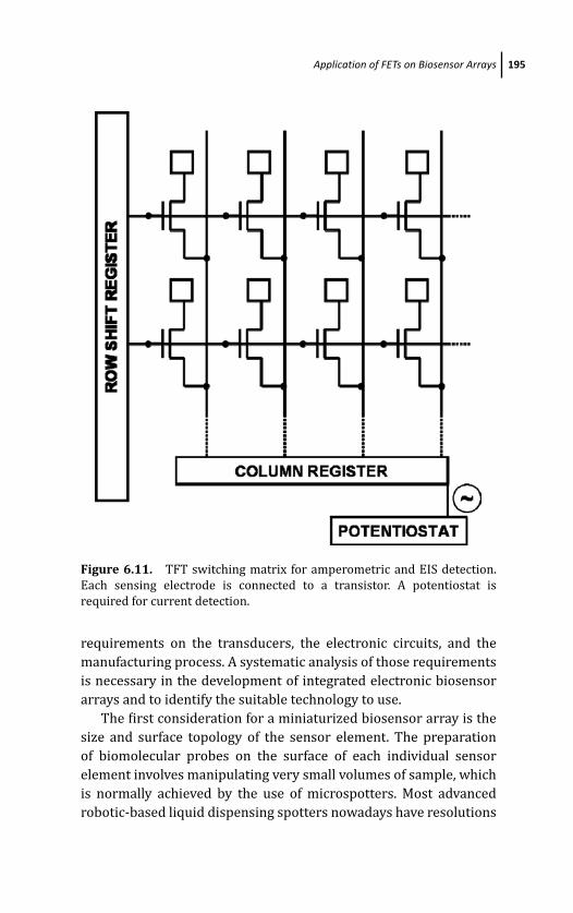
March 14, 2012 20:8 PSP Book - 9in x 6in 06-Ozsoz-c06
Application of FETs on Biosensor Arrays 195
Figure 6.11. TFT switching matrix for amperometric and EIS detection.
Each sensing electrode is connected to a transistor. A potentiostat is
required for current detection.
requirements on the transducers, the electronic circuits, and the
manufacturing process. A systematic analysis of those requirements
is necessary in the development of integrated electronic biosensor
arrays and to identify the suitable technology to use.
The first consideration for a miniaturized biosensor array is the
size and surface topology of the sensor element. The preparation
of biomolecular probes on the surface of each individual sensor
element involves manipulating very small volumes of sample, which
is normally achieved by the use of microspotters. Most advanced
robotic-based liquid dispensing spotters nowadays have resolutions
March 14, 2012 20:8 PSP Book - 9in x 6in 06-Ozsoz-c06
196 Application of Field-Effect Transistors to Label-Free Electrical DNA Biosensor Arrays
down to tens of micrometers, which sets the minimum size of the
sensing area of each individual sensor element, and consequently
the density of the sensor array [40].
The transducing methods also limit the size of sensor elements.
For potentiometric detection, although the signal-to-noise ratio is
independent of the FET dimension, having a larger extended gate
structure can significantly improve the sensitivity of the transducer
[4]. According to the requirements on the sensitivity, it is preferred
to have a ratio between the areas of the extended gate and the
FET gate at 10–100, which results in individual sensor dimensions
of 10–100 μm based on modern microfabrication technologies.
For amperometric detection methods such as EIS, reducing the
size of sensor electrodes leads to a decrease of the current to be
measured. The resistance of the biomolecular layer varies within a
large range—typically between 30 k�cm2 and 5 M�cm2. A reliable
measurement of sub-pA current requires very high performance
electronic devices and complicated circuit design. Therefore, the
typical dimension of amperometric sensors based on ac methods
cannot be smaller than tens of micrometers.
Electronic biosensor transducers, either potentiometric or
amperometric/EIS-based, also require atomically flat surfaces or at
least surfaces with controlled roughness. The underlying consider-
ation is the density of immobilized biomolecular probes and hence
the target captured by the probes in the biomolecular interaction.
It has been shown that the immobilization density depends on the
microscopic area of the sensor surface, which is determined by both
the geometry area and the roughness factor [39]. For measurement
techniques where the amount of charge is of concern, such as
potentiometric detection or chronocoulometric detection, a uniform
surface with regular roughness factor is needed for the entire sensor
array.
Another important consideration is the working frequency. To
characterize the sheer number of sensors in the same array in
real time, both the switching circuit and measurement units need
to work at high enough frequency. The speed needed eventually
depends on the nature and kinetics of the biomolecular interaction
to be measured. For example, considering a typical array with 1,000
elements to be measured in 1 second, the logic circuit to address the
March 14, 2012 20:8 PSP Book - 9in x 6in 06-Ozsoz-c06
Application of FETs on Biosensor Arrays 197
sensor array needs to work at frequencies of ∼104 Hz. Moreover, if
an ac method such as EIS is used as the characterization technique,
all the sensor elements need to be measured in a single period. The
frequency requirement will then be the basic addressing frequency
multiplied by the highest frequency used in EIS, which raises the bar
to around 107 Hz in practice.
Other factors that need to be taken into consideration include
temperature variations induced by the power consumption of the
circuit, lifetime in solution which is determined by the passivation
material, and overall chip size and packaging for practical handling.
Those factors are less important in terms of the use of FET and need
to be reviewed for each application.
6.5.3 Development of Biosensor Arrays Based on FETs
Due to their advantages over conventional optical arrays, electronic
biosensor transducers and arrays have attracted intensive research
interest in recent years. The vast majority of those efforts, however,
are focused on the use of FETs as transducers and only a few
groups have successfully prototyped their array devices [46–54].
The obvious reason for this is the high cost of mask making and chip
fabrication. Among them, the CMOS process dominates due to the
easy access to commercial CMOS foundries.
A configurable electrochemical sensor microarray system-on-a-
chip fabricated in a standard CMOS process has been presented
in the literature [48, 49]. The array had 5 × 10 elements, each
occupying an area of 160 μm × 120 μm and containing a differential
electrochemical transducer with a programmable sensor. The sensor
had a digitally configurable topology capable of performing different
electroanalytical measurements including voltammetry and field-
effect sensing.
In another report, a DNA sensor array of 16 × 8 sensor elements
with pitch size of 250 μm has been fabricated using a 0.5−μm
CMOS process [50, 51, 55]. The DNA hybridization is measured
through the change of interfacial capacitance and then converted to a
digital output signal by the integrated electronics. The chip was post-
processed with a gold layer to facilitate the attachment of probe DNA
March 14, 2012 20:8 PSP Book - 9in x 6in 06-Ozsoz-c06
198 Application of Field-Effect Transistors to Label-Free Electrical DNA Biosensor Arrays
using the thiol-gold chemistry. Successful discrimination between
complementary and mismatched target DNA was demonstrated.
Other examples of CMOS-based field-effect sensor arrays are
used for the monitoring of extracellular electrophysiological signals
or pH changes [56]. Those devices normally involve only ISFETs and
hence are less complicated in structure than those required for DNA
or protein arrays.
AC techniques such as EIS, which demand high electronic
performance, have also been shown on CMOS circuits integrated
with biosensor arrays. Unlike with potentiometric techniques,
the signal of current sensing techniques such as amperometry
and EIS naturally decreases with the electrode size. In addition,
EIS detection requires currents to be measured for a range of
frequencies, which could make the time needed to read the signals
from the entire microarray impractically long. The use of a wide
band stimulus coupled with a fast Fourier transform algorithm has
been proposed to overcome this problem [57]. A saving feature is
that the frequency range to be measured is below 100 Hz.
The aforementioned examples with CMOS processes achieved
success to a certain level, either in the electronic performance or
in measurements with actual biological samples. However, due to
the different fabrication factors, applications and characterization
methods, it is impractical to compare the performance of the
biosensor arrays.
The use of TFTs in electronic biosensor array is still limited.
Various TFT-based DNA and protein transducers have been devel-
oped either with poly-Si or amorphous silicon TFTs [4, 58]. Although
proved to be successful as sensor transducers, working TFT-based
sensor arrays have not reported in the literature. This is largely
attributed to the fact that TFT foundries are mostly specialized
for the manufacturing of LCD backplanes and not commercially
available to researchers.
6.5.4 Fabrication Technologies and Future Trends
From the point of view of electronic biosensor array appli-
cations, both CMOS and TFT technologies clearly have advan-
tages and disadvantages. CMOS represents the state-of-the-art for

March 14, 2012 20:8 PSP Book - 9in x 6in 06-Ozsoz-c06
Application of FETs on Biosensor Arrays 199
microfabrication and can provide devices at tens of nanometers
working at GHz frequency ranges. However, for biosensor arrays this
high performance is far over-specification as previously discussed.
On the other hand, considering manufacturing and convenience of
operation, both the sensor element itself and the whole chip cannot
be made too small. In the existing examples, the size of the chip is
4 mm2 for 50 sensor spots using a 0.18-μm process and 20 mm2
for 128 sensor spots using a 0.5 μm process. Even with this small
number of sensors in the array, using CMOS technology leads to
substantial cost on the manufacturing of the chip, typically a few
dollars in these two cases, excluding the costs of the biomolecular
probes, post-processing, design, and installation fee for the masks.
This cost is mainly due to the expensive single crystal silicon
substrate, and hence would scale up when a larger number of sensor
elements or a larger area for each sensor element is needed. As
disposability is highly desired for biosensor arrays, the high cost of
CMOS process makes it impractical for large scale applications such
as diagnostics and disease screening.
On the other hand, although TFTs cannot provide such high
performance electronic devices, it can be manufactured on much
cheaper substrates such as glass and even plastics, making the
technology an ideal candidate for biosensor arrays in the view
of cost. The main limitation of TFTs is the low mobility of the
semiconductor material. This does not only affect the performance
when it is used as a transducer, but, in case of amorphous TFT, it also
prevents its use for the addressing logic and measurement circuit.
To be used as the addressing matrix switches for individual
sensor elements, the on/off state current ratio is the parameter to be
considered. For a biosensor array with thousands of sensor elements
the off-state resistance must be at least 3 orders of magnitude larger
that of the on-state to secure precise measurement of data. This can
be easily achieved by the use of a single FET based on either CMOS
[5], poly-Si TFT [15], or amorphous-Si TFT [59].
For the logic driving circuit, the TFT needs to work at 104 Hz with
normal sequential measurement, and 107 Hz if time multiplexed EIS
is to be implemented. The highest working frequency of a FET is
mainly determined by the mobility of the semiconductor material,
as well as by its geometry size and fabrication process. It has been

March 14, 2012 20:8 PSP Book - 9in x 6in 06-Ozsoz-c06
200 Application of Field-Effect Transistors to Label-Free Electrical DNA Biosensor Arrays
estimated that due to its low mobility, amorphous silicon TFT would
not work at more than 104 or 105 Hz, which rules it out for the use
of addressing logic circuits in future high density arrays [15]. Poly-
Si TFT, however, has a mobility of over 100 cm2 V−1 s−1 and can
adequately cover the desired frequency range.
For the measurement circuit, the amorphous silicon TFT has not
been considered suitable for analog circuit or high frequency digital
circuit, due to its low mobility and transconductance, while the poly-
Si TFT has been developed into a large variety of analog circuits with
moderate performance. The suitability of the three FET technologies
for biosensor array applications is summarized in Table 6.1.
Overall, polysilicon TFTs can provide all the key components, so
the application to the proposed integrated biosensor arrays is within
the capabilities of the technology. Furthermore, it seems to provide
the proper balance between the performance and cost for future
biosensor array applications, although its current development is
hindered by the lack of commercial foundries for research purposes.
Table 6.1. Advantages and disadvantages of CMOS, poly-Si TFT, and amor-
phous TFT technologies for the development of the different components in
biosensor arrays
Application in biosensor arrays
Addressing Measurement
Transducer switches Driving logic circuit
CMOS FET Pros High internal High speed, High speed High electronic
gain, smaller size high on-off performance,
current ratio compact in size
Cons Expensive to have None None None
larger extended
gate or electrodes
Poly-Si TFT Pros High internal gain High on-off Moderate Moderate
ratio speed performance
Cons Device uniformity None None None
Amorphous Pros Low cost, low Moderate None None
TFT temperature on-off ratio
manufacturing
Cons Very low gain, None Low speed Low electronic
device uniformity performance
March 14, 2012 20:8 PSP Book - 9in x 6in 06-Ozsoz-c06
Conclusions 201
6.6 Conclusions
In conclusion, we have reviewed two highly promising techniques
for label-free biosensor technology. Potentiometric detection offers
the advantage of a simple electrode arrangement, since only two
electrodes are needed. Furthermore, the signal is independent
of the electrode area, which facilitates scaling. Signal readout
and conditioning is straightforward, owing to the in-built cell
amplification.
Noticeable progress has been made in recent years in the appli-
cation of electrochemical impedance spectroscopy to biosensors.
Compared to potentiometric detection, it requires a more complex
electrode arrangement (three electrodes) and a more demanding
detection circuit (potentiostat). In addition, the signal decreases
with the electrode area and the measurements are taken over a
range of frequencies. It is likely that both techniques are used in
the future for different applications. For instance, potentiometric
detection is particularly suitable for real-time detection, while EIS
offers information for both charged and uncharged species.
For both types of techniques, FET technology can provide the
switching matrix and the integrated measurement circuitry. Three
FET technologies including CMOS, poly-Si TFT, and amorphous TFT
have been reviewed and discussed for their use in future disposable
electronic biosensor arrays. Both technical and economic aspects
have been covered to evaluate the future application of these
technologies. Although current research is predominantly focused
on CMOS-based arrays, poly-Si seems to present the best balance
between performance and cost for real-world applications. The
implementation of an all poly-Si FET microarray appears to be
within the capability of the technology. However, the non-scalability
of the EIS technique and the long data acquisition time pose
considerable challenges for the designer and the technologist.
Acknowledgments
The authors would like to thank Dr. S. D. Keighley (Cambridge
University) for help with the experiments and valuable discussions.
March 14, 2012 20:8 PSP Book - 9in x 6in 06-Ozsoz-c06
202 Application of Field-Effect Transistors to Label-Free Electrical DNA Biosensor Arrays
References
1. G. Herzog and D. W. M. Arrigan, Analyst 132, 615 (2007).
2. E. Katz and I. Willner, Electroanalysis 15, 913 (2003).
3. J. S. Daniels and N. Pourmand, Electroanalysis 19, 1239 (2007).
4. P. Estrela and P. Migliorato, J. Mater. Chem. 17, 219 (2007).
5. S. M. Sze, Physics of Semiconductor Devices, 2nd ed., Wiley Interscience,
New York (1981).
6. P. Bergveld, IEEE Trans. Biomed. Eng. 19, 70 (1970).
7. P. Estrela, S. D. Keighley, and P. Migliorato, in Recent Advances inAnalytical Electrochemistry (K. I. Ozoemena, ed.), Transworld Research
Network, Kerala, p. 199 (2007).
8. M. J. Madou and S. R. Morrison, Chemical Sensing with Solid State Devices,
Academic Press, San Diego (1989).
9. M. J. Schoning and A. Poghossian, Analyst 127, 1137 (2002).
10. P. Bergveld, Sens. Actuators B 88, 1 (2003).
11. P. Estrela, D. Paul, Q. Song, L. K. J. Stadler, L. Wang, E. Huq, J. J. Davis, P. Ko
Ferrigno, and P. Migliorato, Anal. Chem. 82, 3531 (2010).
12. P. Migliorato, in Encyclopedia of Physical Science and TechnologyYearbook (R. A. Meyers, ed.), Academic Press, Orlando, p. 599 (1990).
13. T. Kamins, Polycrystalline Silicon for Integrated Circuits and Displays, 2nd
ed., Kluwer Academic, Boston (1998).
14. S. Inoue, S. Utsunomiya, T. Saeki, and T. Shimoda, IEEE Trans. ElectronDev. 49, 1353 (2002).
15. S. D. Brotherton, Semicond. Sci. Technol. 10, 721 (1995).
16. P. Estrela, A. G. Stewart, F. Yan, and P. Migliorato, Electrochim. Acta 50,
4995 (2005).
17. A. W. Peterson, R. J. Heaton, and R. M. Georgiadis, Nucleic Acids Res. 29,
5163 (2001).
18. A. J. Bard and L. R. Faulkner, Electrochemical Measurements, Fundamen-tals and Applications, 2nd ed., John Wiley & Sons, New York (2001).
19. A. Halperin, A. Buhot, and E. B. Zhulina, Biophys. J. 86, 718 (2004).
20. M. T. Record, C. F. Anderson, and T. M. Lohman, Q. Rev. Biophys. 11, 103
(1978).
21. B. Tinland, A. Pluen, J. Sturm, and G. Weill, Macromolecules 30, 5763
(1997).
22. G. S. Manning, Q. Rev. Biophys. 11, 179 (1978).
March 14, 2012 20:8 PSP Book - 9in x 6in 06-Ozsoz-c06
References 203
23. G. S. Manning, Biophys. Chem. 101, 461 (2002).
24. C. Y. Shew and A. Yethiraj, J. Chem. Phys. 116, 5308 (2002).
25. M. Deserno and C. Holm, Mol. Phys. 100, 2941 (2002).
26. M. Deserno, C. Holm, and S. May, Macromolecules 33, 199 (2000).
27. C. F. Anderson and M. T. Record, Annu. Rev. Phys. Chem. 46, 657
(1995).
28. P. S. Crozier and M. J. Stevens, J. Chem. Phys. 118, 3855 (2003).
29. F. S. Csajka, C. C. van der Linden, and C. Seidel, Macromol. Symp. 146, 243
(1999).
30. H. O. Finklea, in Encyclopedia of Analytical Chemistry: Applications,Theory, and Instrumentation (R. A. Meyers, ed.), John Wiley & Sons, New
York (2000).
31. P. Bergveld, Sens. Actuators A. 56, 65 (1996).
32. T. Sakata, M. Kamahori, and Y. Miyahara, Mater. Sci. Eng. C 24, 827
(2004).
33. F. Uslu, S. Ingebrandt, D. Mayer, S. Bocker-Meffert, M. Odenthal, and
A. Offenhausser, Biosens. Bioelectron. 19, 1723 (2004).
34. D. Landheer, G. Aers, W. R. McKinnon, M. J. Deen, and J. C. Ranuarez,
J. Appl. Phys. 98, 044701 (2005).
35. S. D. Keighley, Label-Free Detection of Nucleic Acids by Their IntrinsicMolecular Charge, PhD thesis, University of Cambridge (2008).
36. P. Estrela, D. Paul, P. Li, S. D. Keighley, P. Migliorato, S. Laurenson, and
P. Ko Ferrigno, Electrochim. Acta 53, 6489 (2008).
37. S. D. Keighley, P. Li, P. Estrela, and P. Migliorato, Biosens. Bioelectron. 23,
1291 (2008).
38. S. D. Keighley, P. Estrela, P. Li, and P. Migliorato, Biosens. Bioelectron. 24,
912 (2008).
39. P. Li, A Study of Electrochemical Transduction Mechanisms in BiosensorApplications, PhD thesis, University of Cambridge (2008).
40. M. Schena, Microarray Analysis Wiley, New York (2003).
41. H. J. Muller and T. Roeder, Microarrays, Elsevier, Heidelberg (2005).
42. R. G. Sosnowski, E. Tu, W. F. Butler, J. P. O’Connell, and M. J. Heller, Proc.Natl. Acad. Sci. USA 94, 1119 (1997).
43. F. Fixe, R. Cabeca, V. Chu, D. M. F. Prazeres, G. N. M. Ferreira, and J. P.
Conde, Appl. Phys. Lett. 83, 1465 (2003).
44. P. Estrela, P. Migliorato, H. Takiguchi, H. Fukushima, and P. Migliorato,
Biosens. Bioelectron. 20, 1580 (2005).
March 14, 2012 20:8 PSP Book - 9in x 6in 06-Ozsoz-c06
204 Application of Field-Effect Transistors to Label-Free Electrical DNA Biosensor Arrays
45. P. Estrela, P. Li, S. D. Keighley, and P. Migliorato, J. Korean Phys. Soc. 54,
498 (2009).
46. B. Eversmann, M. Jenkner, F. Hofmann, C. Paulus, R. Brederlow,
B. Holzapfl, P. Fromherz, et al., IEEE J. Solid State Circ. 38, 2306 (2003).
47. C. Guiducci, C. Stagni, G. Zuccheri, A. Bogliolo, L. Benini, B. Samori, and
B. Ricco, Biosens. Bioelectron. 19, 781 (2004).
48. A. Hassibi and T. H. Lee, IEEE Sens. J. 6, 1380 (2006).
49. B. Jang and A. Hassibi, IEEE Trans. Ind. Electron. 56, 979 (2009).
50. C. Stagni, C. Guiducci, L. Benini, B. Ricco, S. Carrara, B. Samori, C. Paulus,
M. Schienle, M. Augustyniak, and R. Thewes, IEEE J. Solid State Circ. 41,
2956 (2006).
51. L. Benini, C. Guiducci, and C. Paulus, IEEE Des. Test Comp. 24, 38 (2007).
52. M. Im, J. H. Ahn, and Y. K. Choi, in Proc. 2008 Int. Soc. Design Conf. 1, 707
(2008).
53. C. Stagni, C. Guiducci, L. Benini, B. Ricco, S. Carrara, C. Paulus, M. Schienle,
and R. Thewes, IEEE Sens. J. 7, 577 (2007).
54. K. Nakazato, Sensors 9, 8831 (2009).
55. M. Schienle, C. Paulus, A. Frey, F. Hofmann, B. Holzapfl, P. Schindler-
Bauer, and R. Thewes, IEEE J. Solid State Circ. 39, 12 (2004).
56. D. Zhu, Y. Sun, and Z. Shi, in Proc. 9th Int. Conf. on Solid-State andIntegrated Circuit Technology, p. 4 (2008).
57. D. Rairigh, A. Mason, and C. Yang, Sens. Lett. 4, 398 (2006).
58. D. Goncalves, D. M. F. Prazeres, V. Chu, and J. P. Conde, Biosens.Bioelectron. 24, 545 (2008).
59. C. Kim, O. Sugiura, and M. Matsumra, in Amorphous Silicon Technology,1993 Symposium (E. A. Schiff, K. Tanaka, M. J. Thompson, A. Madan,
and P. G. LeComber, eds.), Materials Research Society, Pittsburgh, p. 925
(1993).
March 19, 2012 17:0 PSP Book - 9in x 6in 07-Ozsoz-c07
Chapter 7
Electrochemical Detection of BasepairMismatches in DNA Films
Piotr Michal Diakowski, Mohtashim Shamsi,and Heinz-Bernhard KraatzDepartment of Chemistry, University of Toronto at Scarborough, 1265 Military Trail,Toronto, Ontario, M1C 1A4 [email protected]
In recent years, interest in the development of electrochemical
strategies for the detection of basepair mismatches in DNA has
increased dramatically. Electrochemistry-based methods present
a promising alternative for optical detection schemes, and are
attractive because they offer the potential for high speed, high
sensitivity and high throughput detection of mismatches at a
minimal cost. Moreover, electrochemical sensors offer tremendous
advantages in terms of ease of integration and miniaturization,
especially in comparison to their optical counterparts. In this chap-
ter, we provide an overview over recent electrochemical mismatch
detection strategies and summarize the state of the art in this field.
We begin our discussion with the preparation of surfaces and the
immobilization of a capture strand and continue with an overview
of detection strategies that exploit the direct electrochemistry of
nucleobases, the conductive properties of DNA or use hybridization
indicators, intercalators and groove binders. Methods employing
Electrochemical DNA BiosensorsEdited by Mehmet OzsozCopyright c© 2012 Pan Stanford Publishing Pte. Ltd.ISBN 978-981-4241-77-9 (Hardcover), 978-981-4303-98-9 (eBook)www.panstanford.com
March 19, 2012 17:0 PSP Book - 9in x 6in 07-Ozsoz-c07
206 Electrochemical Detection of Basepair Mismatches in DNA Films
synthetic DNA analogues such as peptide nucleic acids (PNA) are
also discussed. Finally, protein and enzyme mediated biosensors,
nanoparticle based sensors, metal ion amplified sensors and a range
of miscellaneous methods is discussed.
7.1 Introduction
The determination of nucleic acid sequences for analytical purposes
has remained a strong research focus for years. Effective and
efficient high-throughput technologies are needed to screen for
genetic defects, identify organisms, and forensic applications. At
present, fluorescence-based techniques are the most commonly
employed. However, wide spread applications of such methods
is limited by low speed, high cost, size, number of incubations
steps, and the need to chemically label the DNA target. In addition,
such systems are far from being foolproof and in some cases false
positives or negatives are observed, making the data interpretation
difficult. Also, integration of the entire optical system into single
portable device is not simple and requires sophisticated fabrica-
tion processes. In contrast, an electrochemistry-based approach
is promising for point-of-care applications and on-site testing
using portable analyzers. What makes such approach attractive
are its inherent advantages of high speed, low cost, simple
instrumentation, and ease of miniaturization of the biosensing
components.
In recent years, numerous electrochemical DNA detection and
sensing methods have been described in the literature. Most
electrochemical detection schemes involve the immobilization of
an oligonucleotide (ODN) onto a transducer surface. Upon the
hybridization of the complementary target sequence to the capture
strand, the binding event is detected in form of an electrochemical
signal. Methods making use of ODN labeling and label-free methods
have been reported. Labels include the use of redox-modified
oligonucleotides, electroactive DNA intercalators, enzymes, metal
complexes and nanoparticles. On the other hand, label-free
approaches are reported that exploit the intrinsic electroactivity of
the DNA bases (guanine and adenine) or monitor changes in the
interfacial properties of the sensing surface, such as changes in the
March 19, 2012 17:0 PSP Book - 9in x 6in 07-Ozsoz-c07
Surface Immobilization 207
capacitance or electron transfer resistance of the film as a function
of hybridization. The latter method is highly versatile and highly
sensitive to the presence of mismatches as will be shown in this
chapter. Synthetic oligonucleotides are often used as the capture
probe. They are readily obtained in high purity and at low cost and
the base sequence can be adjusted to suit a particular target. Peptide
nucleic acids (PNA) can also be used as a capture probe. PNA has
a higher stability and improved binding affinity in comparison to
nucleic acids, but is costly.
Often, as in the case of redox-labeled oligonucleotides, the
covalent attachment of a redox label such as a ferrocene (Fc) group
is achieved by imine and amide formation using Fc-carboxaldehyde
or Fc-carboxylic acid, respectively, and also by Sonogashira coupling
with the corresponding Fc-alkyne derivative [1, 2]. Redox labels
can be introduced either on the monomer stage, by a metal-
catalyzed reaction, or after assembly of the oligomer sequence
[3]. For example, Fc-conjugated nucleotides can be conveniently
used as building blocks in automated oligonucleotide synthesis [4].
Similarly, the Fc group can be introduced after ODN synthesis by
amide coupling of Fc-COOH to a 5’-amino group of a synthetic
ODN, as was reported by Ihara and co-workers [5]. However, the
introduction of a Fc-label into a DNA oligomer can decrease the
stability of the duplex. And the position of the Fc group, the nature
of its linkage to the ODN, and the nucleobase will all influence the
“melting point” of the duplex. The interested reader is referred to a
review [6], where different Fc oligomers are discussed.
In order to be useful for the detection of nucleotide basepair
mismatches, the electrochemical signature of the mismatched ds-
ODN must be significantly different from that of the fully hybridized
ds-ODN. In this chapter, we summarize the state of the art in this
field and provide an overview over capture strand immobilization
strategies and various mismatch detections schemes.
7.2 Surface Immobilization
To design a functional DNA biosensor DNA, capture strands have to
be immobilized on an electrode surface. Thin film formation is often
accomplished by covalent attachment, adsorption or affinity binding
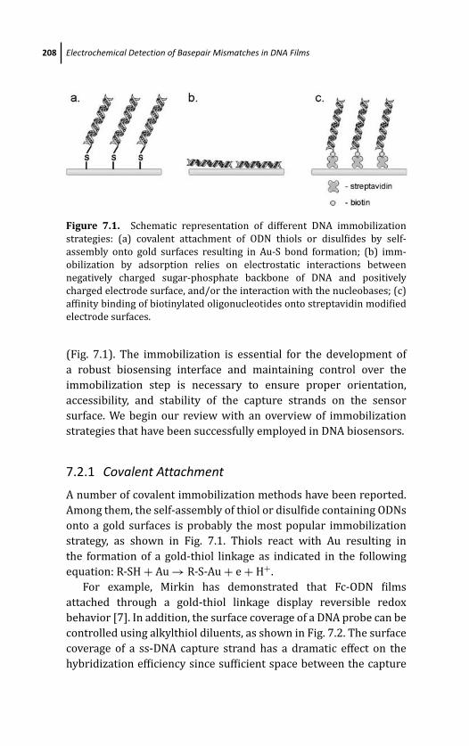
March 19, 2012 17:0 PSP Book - 9in x 6in 07-Ozsoz-c07
208 Electrochemical Detection of Basepair Mismatches in DNA Films
Figure 7.1. Schematic representation of different DNA immobilization
strategies: (a) covalent attachment of ODN thiols or disulfides by self-
assembly onto gold surfaces resulting in Au-S bond formation; (b) imm-
obilization by adsorption relies on electrostatic interactions between
negatively charged sugar-phosphate backbone of DNA and positively
charged electrode surface, and/or the interaction with the nucleobases; (c)
affinity binding of biotinylated oligonucleotides onto streptavidin modified
electrode surfaces.
(Fig. 7.1). The immobilization is essential for the development of
a robust biosensing interface and maintaining control over the
immobilization step is necessary to ensure proper orientation,
accessibility, and stability of the capture strands on the sensor
surface. We begin our review with an overview of immobilization
strategies that have been successfully employed in DNA biosensors.
7.2.1 Covalent Attachment
A number of covalent immobilization methods have been reported.
Among them, the self-assembly of thiol or disulfide containing ODNs
onto a gold surfaces is probably the most popular immobilization
strategy, as shown in Fig. 7.1. Thiols react with Au resulting in
the formation of a gold-thiol linkage as indicated in the following
equation: R-SH + Au → R-S-Au + e + H+.
For example, Mirkin has demonstrated that Fc-ODN films
attached through a gold-thiol linkage display reversible redox
behavior [7]. In addition, the surface coverage of a DNA probe can be
controlled using alkylthiol diluents, as shown in Fig. 7.2. The surface
coverage of a ss-DNA capture strand has a dramatic effect on the
hybridization efficiency since sufficient space between the capture
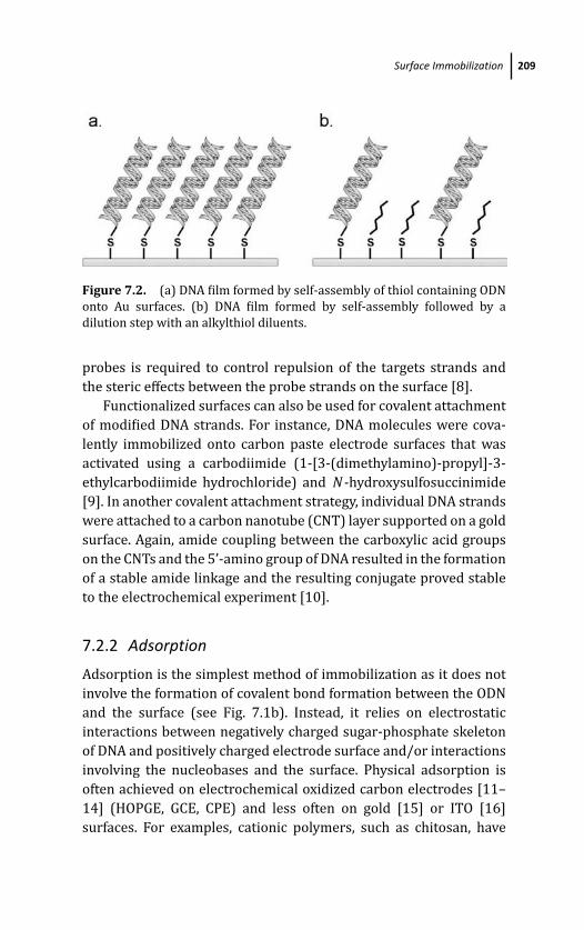
March 19, 2012 17:0 PSP Book - 9in x 6in 07-Ozsoz-c07
Surface Immobilization 209
Figure 7.2. (a) DNA film formed by self-assembly of thiol containing ODN
onto Au surfaces. (b) DNA film formed by self-assembly followed by a
dilution step with an alkylthiol diluents.
probes is required to control repulsion of the targets strands and
the steric effects between the probe strands on the surface [8].
Functionalized surfaces can also be used for covalent attachment
of modified DNA strands. For instance, DNA molecules were cova-
lently immobilized onto carbon paste electrode surfaces that was
activated using a carbodiimide (1-[3-(dimethylamino)-propyl]-3-
ethylcarbodiimide hydrochloride) and N -hydroxysulfosuccinimide
[9]. In another covalent attachment strategy, individual DNA strands
were attached to a carbon nanotube (CNT) layer supported on a gold
surface. Again, amide coupling between the carboxylic acid groups
on the CNTs and the 5’-amino group of DNA resulted in the formation
of a stable amide linkage and the resulting conjugate proved stable
to the electrochemical experiment [10].
7.2.2 Adsorption
Adsorption is the simplest method of immobilization as it does not
involve the formation of covalent bond formation between the ODN
and the surface (see Fig. 7.1b). Instead, it relies on electrostatic
interactions between negatively charged sugar-phosphate skeleton
of DNA and positively charged electrode surface and/or interactions
involving the nucleobases and the surface. Physical adsorption is
often achieved on electrochemical oxidized carbon electrodes [11–
14] (HOPGE, GCE, CPE) and less often on gold [15] or ITO [16]
surfaces. For examples, cationic polymers, such as chitosan, have
March 19, 2012 17:0 PSP Book - 9in x 6in 07-Ozsoz-c07
210 Electrochemical Detection of Basepair Mismatches in DNA Films
been successfully used to modify carbon electrodes [17]. Also, a
positive potential bias can be applied to the electrode to improve
the adsorption of the DNA. However, the main disadvantage of this
approach is the need for a strong affinity of the DNA to the surface,
which results in a multipoint attachment of the capture strand, thus
affecting the hybridization efficiency as the probe is restricted by
multipoint immobilization. In some cases, problems are associated
with the stability of the films.
7.2.3 Affinity Binding
Strong interactions between avidin and biotin can be exploited
in the preparation of useful sensing surfaces [18]. The stability
of the avidin-biotin binding is on par with that of covalent
attachment. Typically, avidin (or streptavidin) is first immobilized
on the transducer surface followed by binding of the biotinylated
oligonucleotides (see Fig. 7.1c) [19]. For instance, avidin can be
covalently bound to gold [20] or physically adsorbed on gold [21] or
carbon electrodes [22]. In one of the examples, avidin was adsorbed
onto a silica surface before immobilizing a biotinylated molecular
beacon (MB) [23]. Alternatively, biotin can be immobilized on the
surface followed by avidin binding allowing for further attachment
of biotinylated DNA probes. In one of the examples, polypyrrole
(PPy) was formed on the electrode, and the biotin units attached to
the film were used as anchoring points for the avidin immobilization
providing three binding sites on the avidin [24].
7.3 Detection Strategies
Numerous electrochemical strategies have been developed for the
detection of mismatches in DNA. These vary from the use of electro-
active DNA intercalators to enzymatic signal amplification schemes,
or redox-modified oligonucleotides. In the following sections, we
will focus on the discussion of a range of electrochemical mismatch
detection schemes.
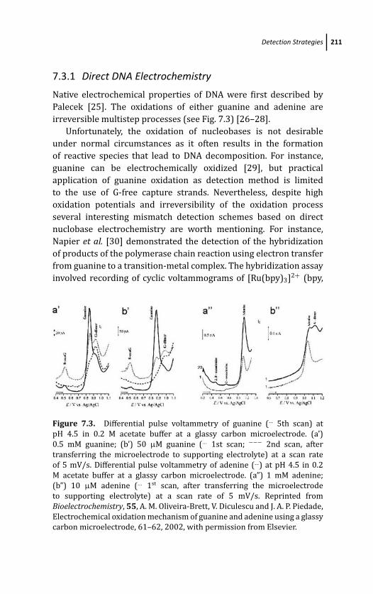
March 19, 2012 17:0 PSP Book - 9in x 6in 07-Ozsoz-c07
Detection Strategies 211
7.3.1 Direct DNA Electrochemistry
Native electrochemical properties of DNA were first described by
Palecek [25]. The oxidations of either guanine and adenine are
irreversible multistep processes (see Fig. 7.3) [26–28].
Unfortunately, the oxidation of nucleobases is not desirable
under normal circumstances as it often results in the formation
of reactive species that lead to DNA decomposition. For instance,
guanine can be electrochemically oxidized [29], but practical
application of guanine oxidation as detection method is limited
to the use of G-free capture strands. Nevertheless, despite high
oxidation potentials and irreversibility of the oxidation process
several interesting mismatch detection schemes based on direct
nuclobase electrochemistry are worth mentioning. For instance,
Napier et al. [30] demonstrated the detection of the hybridization
of products of the polymerase chain reaction using electron transfer
from guanine to a transition-metal complex. The hybridization assay
involved recording of cyclic voltammograms of [Ru(bpy)3]2+ (bpy,
Figure 7.3. Differential pulse voltammetry of guanine ( 5th scan) at
pH 4.5 in 0.2 M acetate buffer at a glassy carbon microelectrode. (a’)
0.5 mM guanine; (b’) 50 μM guanine (... 1st scan; −−− 2nd scan, after
transferring the microelectrode to supporting electrolyte) at a scan rate
of 5 mV/s. Differential pulse voltammetry of adenine ( ) at pH 4.5 in 0.2
M acetate buffer at a glassy carbon microelectrode. (a”) 1 mM adenine;
(b”) 10 μM adenine (... 1st scan, after transferring the microelectrode
to supporting electrolyte) at a scan rate of 5 mV/s. Reprinted from
Bioelectrochemistry, 55, A. M. Oliveira-Brett, V. Diculescu and J. A. P. Piedade,
Electrochemical oxidation mechanism of guanine and adenine using a glassy
carbon microelectrode, 61–62, 2002, with permission from Elsevier.

March 19, 2012 17:0 PSP Book - 9in x 6in 07-Ozsoz-c07
212 Electrochemical Detection of Basepair Mismatches in DNA Films
2,2’-bipyridine) in the presence of an unhybridized probe strand
containing only A, T, and C. Upon hybridization to a complement
that contained seven guanines, a high catalytic current was observed
due to the oxidation of guanine by [Ru(bpy)3]3+. The metal complex
acting as a mediator was activated at potentials accessible in the
neutral aqueous solutions. This sensor design was tested in a
model system, which showed a charge increase of 35 ± 5 μC for
complementary strand and only 8 ± 5 μC for non-complementary
DNA strand. Furthermore, for PCR-amplified genomic DNA from
herpes simplex virus type II, 35–65 μC and 2–10 μC increase in
charge was observed for complementary and non-complementary
DNA respectively. Another interesting application of direct guanine
and adenine oxidation for mismatch detection was reported by Wei
and coworkers [31]. Catalytic guanine and adenine oxidation was
achieved using tris(2,20-bipyridyl)ruthenium(II) modified glassy
carbon (GC) electrodes, resulting in DNA detection by electro-
chemiluminescence (ECL). Interestingly, the modified GC electrodes
were prepared by casting a CNT/Nafion/Ru(bpy)32+ composite
film on the electrode surface. The method allowed for sensitive
single-base mismatch detection of the p53 gene sequence segment
(3.93 × 10⁻¹⁰ mol/L) by employing cyclic voltammetry stimulation.
Consequently, the observed ECL signal for a C/A mismatched ODN
was 1.5 times higher than that of the fully matched ODN.
7.3.2 Charge Transduction Through DNA
A different approach to sensing DNA mismatches takes advantage
of the distinctive electronic properties of DNA and potential
differences that exist between fully matched and mismatched ODNs.
Long range charge transport facilitated by the DNA π -stack is often
exploited in various DNA mismatch detection schemes as it has
been shown to be dependent on the presence of mismatches in
the double-strand. Furthermore, DNA mediated reactions weakly
depend on distance but are extremely sensitive to perturbations
in the base stack. Single-base mismatches induce only small
changes in the duplex structure/stability, but they create significant
perturbations in the electronic structure of the base-pair stack [32–
34]. Detection schemes based on the charge transport through DNA
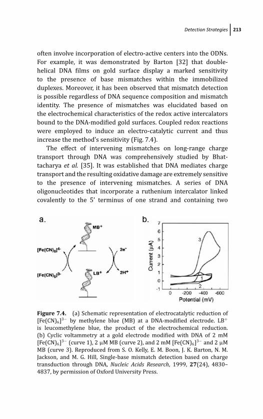
March 19, 2012 17:0 PSP Book - 9in x 6in 07-Ozsoz-c07
Detection Strategies 213
often involve incorporation of electro-active centers into the ODNs.
For example, it was demonstrated by Barton [32] that double-
helical DNA films on gold surface display a marked sensitivity
to the presence of base mismatches within the immobilized
duplexes. Moreover, it has been observed that mismatch detection
is possible regardless of DNA sequence composition and mismatch
identity. The presence of mismatches was elucidated based on
the electrochemical characteristics of the redox active intercalators
bound to the DNA-modified gold surfaces. Coupled redox reactions
were employed to induce an electro-catalytic current and thus
increase the method’s sensitivity (Fig. 7.4).
The effect of intervening mismatches on long-range charge
transport through DNA was comprehensively studied by Bhat-
tacharya et al. [35]. It was established that DNA mediates charge
transport and the resulting oxidative damage are extremely sensitive
to the presence of intervening mismatches. A series of DNA
oligonucleotides that incorporate a ruthenium intercalator linked
covalently to the 5’ terminus of one strand and containing two
Figure 7.4. (a) Schematic representation of electrocatalytic reduction of
[Fe(CN)6]3− by methylene blue (MB) at a DNA-modified electrode. LB+
is leucomethylene blue, the product of the electrochemical reduction.
(b) Cyclic voltammetry at a gold electrode modified with DNA of 2 mM
[Fe(CN)6]3− (curve 1), 2 μM MB (curve 2), and 2 mM [Fe(CN)6]3− and 2 μM
MB (curve 3). Reproduced from S. O. Kelly, E. M. Boon, J. K. Barton, N. M.
Jackson, and M. G. Hill, Single-base mismatch detection based on charge
transduction through DNA, Nucleic Acids Research, 1999, 27(24), 4830–
4837, by permission of Oxford University Press.
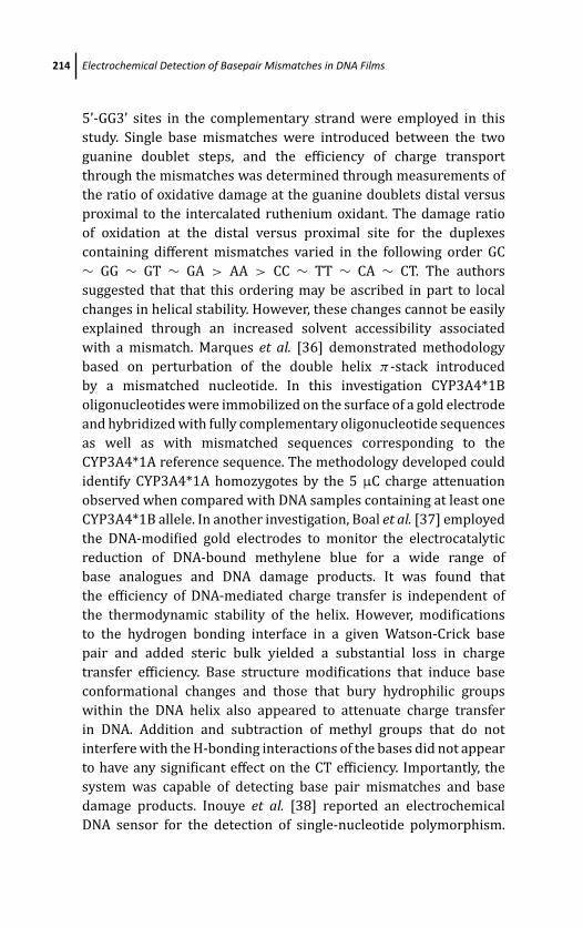
March 19, 2012 17:0 PSP Book - 9in x 6in 07-Ozsoz-c07
214 Electrochemical Detection of Basepair Mismatches in DNA Films
5’-GG3’ sites in the complementary strand were employed in this
study. Single base mismatches were introduced between the two
guanine doublet steps, and the efficiency of charge transport
through the mismatches was determined through measurements of
the ratio of oxidative damage at the guanine doublets distal versus
proximal to the intercalated ruthenium oxidant. The damage ratio
of oxidation at the distal versus proximal site for the duplexes
containing different mismatches varied in the following order GC
∼ GG ∼ GT ∼ GA > AA > CC ∼ TT ∼ CA ∼ CT. The authors
suggested that that this ordering may be ascribed in part to local
changes in helical stability. However, these changes cannot be easily
explained through an increased solvent accessibility associated
with a mismatch. Marques et al. [36] demonstrated methodology
based on perturbation of the double helix π -stack introduced
by a mismatched nucleotide. In this investigation CYP3A4*1B
oligonucleotides were immobilized on the surface of a gold electrode
and hybridized with fully complementary oligonucleotide sequences
as well as with mismatched sequences corresponding to the
CYP3A4*1A reference sequence. The methodology developed could
identify CYP3A4*1A homozygotes by the 5 μC charge attenuation
observed when compared with DNA samples containing at least one
CYP3A4*1B allele. In another investigation, Boal et al. [37] employed
the DNA-modified gold electrodes to monitor the electrocatalytic
reduction of DNA-bound methylene blue for a wide range of
base analogues and DNA damage products. It was found that
the efficiency of DNA-mediated charge transfer is independent of
the thermodynamic stability of the helix. However, modifications
to the hydrogen bonding interface in a given Watson-Crick base
pair and added steric bulk yielded a substantial loss in charge
transfer efficiency. Base structure modifications that induce base
conformational changes and those that bury hydrophilic groups
within the DNA helix also appeared to attenuate charge transfer
in DNA. Addition and subtraction of methyl groups that do not
interfere with the H-bonding interactions of the bases did not appear
to have any significant effect on the CT efficiency. Importantly, the
system was capable of detecting base pair mismatches and base
damage products. Inouye et al. [38] reported an electrochemical
DNA sensor for the detection of single-nucleotide polymorphism.
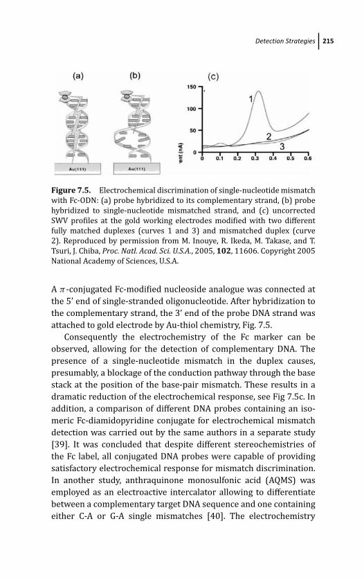
March 19, 2012 17:0 PSP Book - 9in x 6in 07-Ozsoz-c07
Detection Strategies 215
Figure 7.5. Electrochemical discrimination of single-nucleotide mismatch
with Fc-ODN: (a) probe hybridized to its complementary strand, (b) probe
hybridized to single-nucleotide mismatched strand, and (c) uncorrected
SWV profiles at the gold working electrodes modified with two different
fully matched duplexes (curves 1 and 3) and mismatched duplex (curve
2). Reproduced by permission from M. Inouye, R. Ikeda, M. Takase, and T.
Tsuri, J. Chiba, Proc. Natl. Acad. Sci. U.S.A., 2005, 102, 11606. Copyright 2005
National Academy of Sciences, U.S.A.
A π -conjugated Fc-modified nucleoside analogue was connected at
the 5’ end of single-stranded oligonucleotide. After hybridization to
the complementary strand, the 3’ end of the probe DNA strand was
attached to gold electrode by Au-thiol chemistry, Fig. 7.5.
Consequently the electrochemistry of the Fc marker can be
observed, allowing for the detection of complementary DNA. The
presence of a single-nucleotide mismatch in the duplex causes,
presumably, a blockage of the conduction pathway through the base
stack at the position of the base-pair mismatch. These results in a
dramatic reduction of the electrochemical response, see Fig 7.5c. In
addition, a comparison of different DNA probes containing an iso-
meric Fc-diamidopyridine conjugate for electrochemical mismatch
detection was carried out by the same authors in a separate study
[39]. It was concluded that despite different stereochemistries of
the Fc label, all conjugated DNA probes were capable of providing
satisfactory electrochemical response for mismatch discrimination.
In another study, anthraquinone monosulfonic acid (AQMS) was
employed as an electroactive intercalator allowing to differentiate
between a complementary target DNA sequence and one containing
either C-A or G-A single mismatches [40]. The electrochemistry
March 19, 2012 17:0 PSP Book - 9in x 6in 07-Ozsoz-c07
216 Electrochemical Detection of Basepair Mismatches in DNA Films
resulting from electron transfer through the DNA to intercalated
AQMS is readily distinguished from that of AQMS on the electrode
surface. The difference in the chemical environment between
free and intercalated AQMS greatly affects its reduction potential,
allowing monitoring of DNA hybridization in real time. In another
study, Gorodetsky et al. [41] utilized DNA duplexes functionalized
with pyrene to fabricate DNA-modified electrodes on highly oriented
pyrolytic graphite (HOPG). The reduction of DNA-bound intercala-
tors was observed as a consequence of a DNA-mediated reaction.
The reduction of the intercalator was attenuated in the presence of
the single-base mismatches, CA and GT, independent of the sequence
composition of the ODN. Sensitivity to single-base mismatches
is enhanced when methylene blue reduction is coupled in an
electrocatalytic cycle with ferricyanide. Furthermore, utilization of
HOPG as electrode material allowed authors to investigate the
electrochemistry of previously inaccessible metallointercalators,
[Ru(bpy)2dppz]2+ and [Os(phen)2dppz]2+, at the DNA-modified
HOPG surface. It was shown that HOPG presents a suitable and
reproducible surface for electrochemical DNA sensors exploiting the
charge transport properties of DNA. Again, Gorodetsky et al. shown
that DNA-mediated electrochemistry can promote reactions at a
distance on the DNA sugar-phosphate backbone [42]. It was pointed
out that relative current densities for DNA-mediated disulfide
reductions of 1.8 μA/cm2 differed significantly from that for well
stacked intercalator reduction of about 80 μA/cm2.
7.3.3 Hybridization Indicators, Intercalators and GrooveBinders
Various molecules are capable to bind to the DNA duplex or to single-
stranded DNA. The application of DNA binding molecules for the
detection of base-pair mismatches is discussed below. For instance,
Millan et al. demonstrated sequence-selective electrochemical DNA
sensing using hybridization indicators [9]. In this detection scheme,
DNA capture strands were covalently immobilized on a glassy
carbon 14 electrode and [Co(bpy)3]3+ and [Co(phen)3]3+ served
as hybridization indicators that display reversible redox behavior.
Presumably, electrostatic interactions with the negatively charged
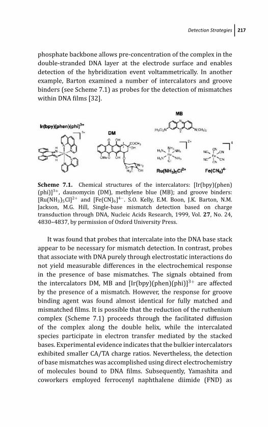
March 19, 2012 17:0 PSP Book - 9in x 6in 07-Ozsoz-c07
Detection Strategies 217
phosphate backbone allows pre-concentration of the complex in the
double-stranded DNA layer at the electrode surface and enables
detection of the hybridization event voltammetrically. In another
example, Barton examined a number of intercalators and groove
binders (see Scheme 7.1) as probes for the detection of mismatches
within DNA films [32].
Scheme 7.1. Chemical structures of the intercalators: [Ir(bpy)(phen)
(phi)]3+, daunomycin (DM), methylene blue (MB); and groove binders:
[Ru(NH3)5Cl]2+ and [Fe(CN)6]4−. S.O. Kelly, E.M. Boon, J.K. Barton, N.M.
Jackson, M.G. Hill, Single-base mismatch detection based on charge
transduction through DNA, Nucleic Acids Research, 1999, Vol. 27, No. 24,
4830–4837, by permission of Oxford University Press.
It was found that probes that intercalate into the DNA base stack
appear to be necessary for mismatch detection. In contrast, probes
that associate with DNA purely through electrostatic interactions do
not yield measurable differences in the electrochemical response
in the presence of base mismatches. The signals obtained from
the intercalators DM, MB and [Ir(bpy)(phen)(phi)]3+ are affected
by the presence of a mismatch. However, the response for groove
binding agent was found almost identical for fully matched and
mismatched films. It is possible that the reduction of the ruthenium
complex (Scheme 7.1) proceeds through the facilitated diffusion
of the complex along the double helix, while the intercalated
species participate in electron transfer mediated by the stacked
bases. Experimental evidence indicates that the bulkier intercalators
exhibited smaller CA/TA charge ratios. Nevertheless, the detection
of base mismatches was accomplished using direct electrochemistry
of molecules bound to DNA films. Subsequently, Yamashita and
coworkers employed ferrocenyl naphthalene diimide (FND) as
March 19, 2012 17:0 PSP Book - 9in x 6in 07-Ozsoz-c07
218 Electrochemical Detection of Basepair Mismatches in DNA Films
redox active intercalator to detect presence of mismatches in 20-mer
(sequence of the lac Z gene) double-stranded ODNs immobilized on
gold electrodes [43]. The FND concentrates at the sensor/solution
interface upon formation of the double strand giving rise to electro-
chemical signal proportional to amount of DNA target. FND does not
bind to the vicinity of mismatched bases resulting in lower current in
the presence of a mismatch. Different mismatches were detected by
differential pulse voltammetric measurements in this study. Another
group reported the detection of hybridization using [Co(byp)3]3+ as
redox active intercalator by cyclic voltammetry measurements [44].
The sensing interface was prepared on gold colloid modified glassy
carbon electrode. The study involved a thorough optimization of
the experimental conditions, including the preparation of the ODN
probes, the hybridization with targets, and of the electrochemical
conditions. The investigation showed that an electrochemical signal
was observed only in the presence of ds-DNA and that 5, 3 and 1 base
mismatches could be clearly discriminated from a fully matched ds-
DNA film. In another report, Kara et al. covalently immobilized 22-
mer single stranded ODN capture probes related to both HSV Type I
and Type II sequences on pencil graphite electrodes [45]. The extent
of hybridization between probe and target sequences obtained from
PCR was determined by DPV in the presence of Meldola Blue (MDB)
as hybridization indicator. Interactions between MDB and the DNA
at the electrode surface resulted in a significantly lower signal
in the case of a 4-base mismatch sequences than in the case of
fully matched sequence. Again, MB was employed by Ostana and
coworkers to electrochemically screen DNA for lesions caused by
de-amination of nucleobases [46]. The damaged DNA was modeled
by 18-mer ODNs containing a different number of mismatched
target bases (uracil instead of cytosine). It was shown that the
amplitude of the reduction signal corresponding to ferricyanide ions
considerably increases in the presence of MB. This electrocatalytic
effect allowed the detection of changes in electrochemical properties
of DNA caused by dUd dG mismatches. Using differential pulse
voltammetry and cyclic voltammetry, the authors showed that the
electron transport from the electrode through the double-stranded
DNA to MB and then to ferricyanide ions is suppressed by the
presence of mismatches in the ODN sequence. MB was also used

March 19, 2012 17:0 PSP Book - 9in x 6in 07-Ozsoz-c07
Detection Strategies 219
by Gorodetsky et al. who utilized duplex DNA functionalized with
pyrene to fabricate DNA-modified electrodes on highly oriented
pyrolytic graphite (HOPG) [41]. As expected, the reduction of the
intercalator was attenuated in the presence of the single-base
mismatches, CA and GT, independent of the sequence composition
of the oligonucleotide. Furthermore, the extended potential range
afforded by the HOPG surface has allowed the authors to investigate
the electrochemistry of previously inaccessible metallointercalators,
[Ru(bpy)2dppz]2+ and [Os(phen)2dppz]2+, at the DNA-modified
HOPG surface. These results support the application of DNA-
modified HOPG as a convenient and reproducible surface for elec-
trochemical DNA sensors using DNA-mediated charge transport. MB
was also used in practical sensor design utilizing a CeO2/chitosan
composite matrix to increase the loading of the ss-DNA probe and
to enhance the biosensor’s response performance [47]. The use
of an interesting ruthenium complex as a sensitive and selective
electrochemical indicator in DNA sensing was reported by Garcia
et al. [48] The ruthenium complex, Ru(NH3)5-[3-(2-phenanthren-9-
yl-vinyl)-pyridine] generated in situ incorporates dual functionali-
ties. The Ru center provides a redox probe and the ligand provides
a fluorescent tag. The presence of the aromatic groups in the
ligand endows the complex with an intercalative character and
makes it able to bind to ds-DNA more efficiently than to ss-DNA.
Combination of spectroscopic and electrochemical studies indicated
fundamentally intercalative interactions between the complex and
ds-DNA. The ligand-based fluorescence allows the characterization
of the complex formation and monitoring of duplex melting.
The metal-based redox center is employed as an electrochemical
indicator to detect the hybridization event in a DNA biosensor.
The sensing surface was prepared by incubation a Au electrode
with a thiolated ss-DNA based on a short DNA sequence from
Helicobacter pylori. With the use of this approach, complementary
target sequences of H.pylori can be quantified with a detection limit
of 92 pmol. In addition, this approach allows the detection of not
only a single mismatch but also its position in a specific sequence
of H. pylori, due to the selective interaction of this bifunctional
ruthenium complex with ds-DNA. A new electroactive intercalator,
Cd(II)-morin, (Scheme 7.2) was reported by Niu et al. [49].
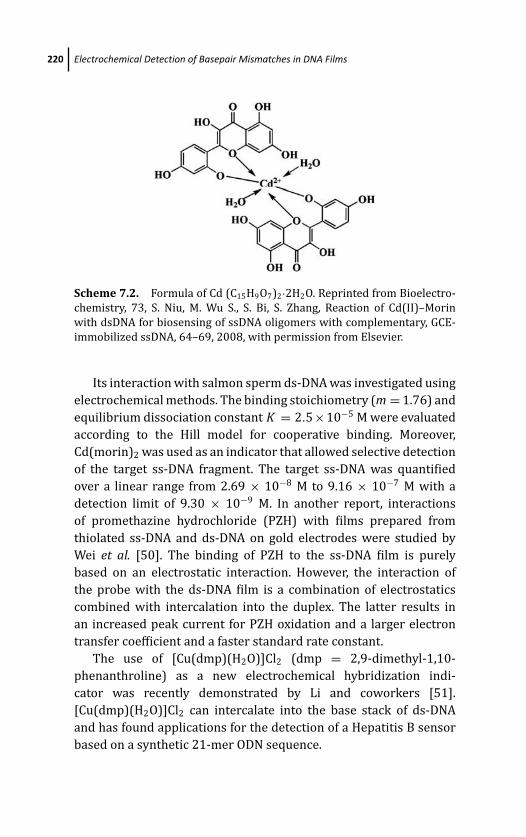
March 19, 2012 17:0 PSP Book - 9in x 6in 07-Ozsoz-c07
220 Electrochemical Detection of Basepair Mismatches in DNA Films
Scheme 7.2. Formula of Cd (C15H9O7)2·2H2O. Reprinted from Bioelectro-
chemistry, 73, S. Niu, M. Wu S., S. Bi, S. Zhang, Reaction of Cd(II)–Morin
with dsDNA for biosensing of ssDNA oligomers with complementary, GCE-
immobilized ssDNA, 64–69, 2008, with permission from Elsevier.
Its interaction with salmon sperm ds-DNA was investigated using
electrochemical methods. The binding stoichiometry (m = 1.76) and
equilibrium dissociation constant K = 2.5×10⁻⁵ M were evaluated
according to the Hill model for cooperative binding. Moreover,
Cd(morin)2 was used as an indicator that allowed selective detection
of the target ss-DNA fragment. The target ss-DNA was quantified
over a linear range from 2.69 × 10⁻⁸ M to 9.16 × 10⁻⁷ M with a
detection limit of 9.30 × 10⁻⁹ M. In another report, interactions
of promethazine hydrochloride (PZH) with films prepared from
thiolated ss-DNA and ds-DNA on gold electrodes were studied by
Wei et al. [50]. The binding of PZH to the ss-DNA film is purely
based on an electrostatic interaction. However, the interaction of
the probe with the ds-DNA film is a combination of electrostatics
combined with intercalation into the duplex. The latter results in
an increased peak current for PZH oxidation and a larger electron
transfer coefficient and a faster standard rate constant.
The use of [Cu(dmp)(H2O)]Cl2 (dmp = 2,9-dimethyl-1,10-
phenanthroline) as a new electrochemical hybridization indi-
cator was recently demonstrated by Li and coworkers [51].
[Cu(dmp)(H2O)]Cl2 can intercalate into the base stack of ds-DNA
and has found applications for the detection of a Hepatitis B sensor
based on a synthetic 21-mer ODN sequence.
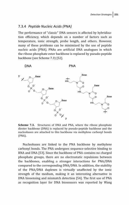
March 19, 2012 17:0 PSP Book - 9in x 6in 07-Ozsoz-c07
Detection Strategies 221
7.3.4 Peptide Nucleic Acids (PNA)
The performance of “classic” DNA sensors is affected by hybridiza-
tion efficiency, which depends on a number of factors such as
temperature, ionic strength, probe length, and others. However,
many of these problems can be minimized by the use of peptide
nucleic acids (PNA). PNAs are artificial DNA analogues in which
the ribose phosphate ester backbone is replaced by pseudo-peptide
backbone (see Scheme 7.3) [52].
Scheme 7.3. Structures of DNA and PNA, where the ribose phosphate
diester backbone (DNA) is replaced by pseudo-peptide backbone and the
nucleobases are attached to this backbone via methylene carbonyl bonds
(PNA).
Nucleobases are linked to the PNA backbone by methylene
carbonyl bonds. The PNA undergoes sequence-selective binding to
RNA and DNA [53]. Since the backbone of PNA contains no charged
phosphate groups, there are no electrostatic repulsions between
the backbones, enabling a stronger interactions for PNA/DNA
compared to the corresponding DNA/DNA. In addition, the stability
of the PNA/DNA duplexes is virtually unaffected by the ionic
strength of the medium, making it an interesting alternative in
DNA biosensing and mismatch detection [54]. The first use of PNA
as recognition layer for DNA biosensors was reported by Wang
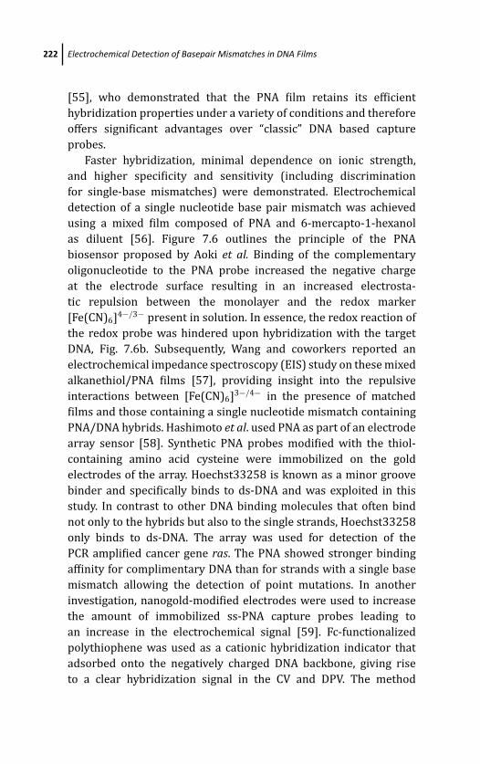
March 19, 2012 17:0 PSP Book - 9in x 6in 07-Ozsoz-c07
222 Electrochemical Detection of Basepair Mismatches in DNA Films
[55], who demonstrated that the PNA film retains its efficient
hybridization properties under a variety of conditions and therefore
offers significant advantages over “classic” DNA based capture
probes.
Faster hybridization, minimal dependence on ionic strength,
and higher specificity and sensitivity (including discrimination
for single-base mismatches) were demonstrated. Electrochemical
detection of a single nucleotide base pair mismatch was achieved
using a mixed film composed of PNA and 6-mercapto-1-hexanol
as diluent [56]. Figure 7.6 outlines the principle of the PNA
biosensor proposed by Aoki et al. Binding of the complementary
oligonucleotide to the PNA probe increased the negative charge
at the electrode surface resulting in an increased electrosta-
tic repulsion between the monolayer and the redox marker
[Fe(CN)6]4−/3− present in solution. In essence, the redox reaction of
the redox probe was hindered upon hybridization with the target
DNA, Fig. 7.6b. Subsequently, Wang and coworkers reported an
electrochemical impedance spectroscopy (EIS) study on these mixed
alkanethiol/PNA films [57], providing insight into the repulsive
interactions between [Fe(CN)6]3−/4− in the presence of matched
films and those containing a single nucleotide mismatch containing
PNA/DNA hybrids. Hashimoto et al. used PNA as part of an electrode
array sensor [58]. Synthetic PNA probes modified with the thiol-
containing amino acid cysteine were immobilized on the gold
electrodes of the array. Hoechst33258 is known as a minor groove
binder and specifically binds to ds-DNA and was exploited in this
study. In contrast to other DNA binding molecules that often bind
not only to the hybrids but also to the single strands, Hoechst33258
only binds to ds-DNA. The array was used for detection of the
PCR amplified cancer gene ras. The PNA showed stronger binding
affinity for complimentary DNA than for strands with a single base
mismatch allowing the detection of point mutations. In another
investigation, nanogold-modified electrodes were used to increase
the amount of immobilized ss-PNA capture probes leading to
an increase in the electrochemical signal [59]. Fc-functionalized
polythiophene was used as a cationic hybridization indicator that
adsorbed onto the negatively charged DNA backbone, giving rise
to a clear hybridization signal in the CV and DPV. The method
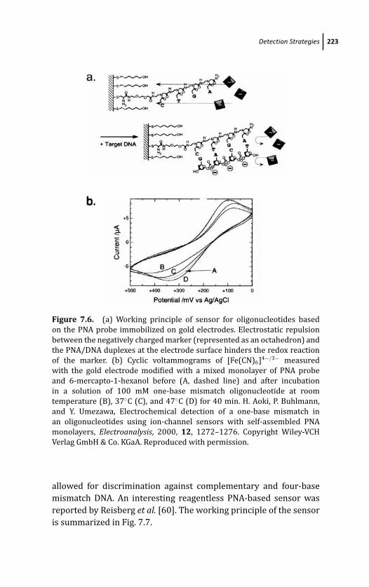
March 19, 2012 17:0 PSP Book - 9in x 6in 07-Ozsoz-c07
Detection Strategies 223
Figure 7.6. (a) Working principle of sensor for oligonucleotides based
on the PNA probe immobilized on gold electrodes. Electrostatic repulsion
between the negatively charged marker (represented as an octahedron) and
the PNA/DNA duplexes at the electrode surface hinders the redox reaction
of the marker. (b) Cyclic voltammograms of [Fe(CN)6]4−/3− measured
with the gold electrode modified with a mixed monolayer of PNA probe
and 6-mercapto-1-hexanol before (A, dashed line) and after incubation
in a solution of 100 mM one-base mismatch oligonucleotide at room
temperature (B), 37◦C (C), and 47◦C (D) for 40 min. H. Aoki, P. Buhlmann,
and Y. Umezawa, Electrochemical detection of a one-base mismatch in
an oligonucleotides using ion-channel sensors with self-assembled PNA
monolayers, Electroanalysis, 2000, 12, 1272–1276. Copyright Wiley-VCH
Verlag GmbH & Co. KGaA. Reproduced with permission.
allowed for discrimination against complementary and four-base
mismatch DNA. An interesting reagentless PNA-based sensor was
reported by Reisberg et al. [60]. The working principle of the sensor
is summarized in Fig. 7.7.
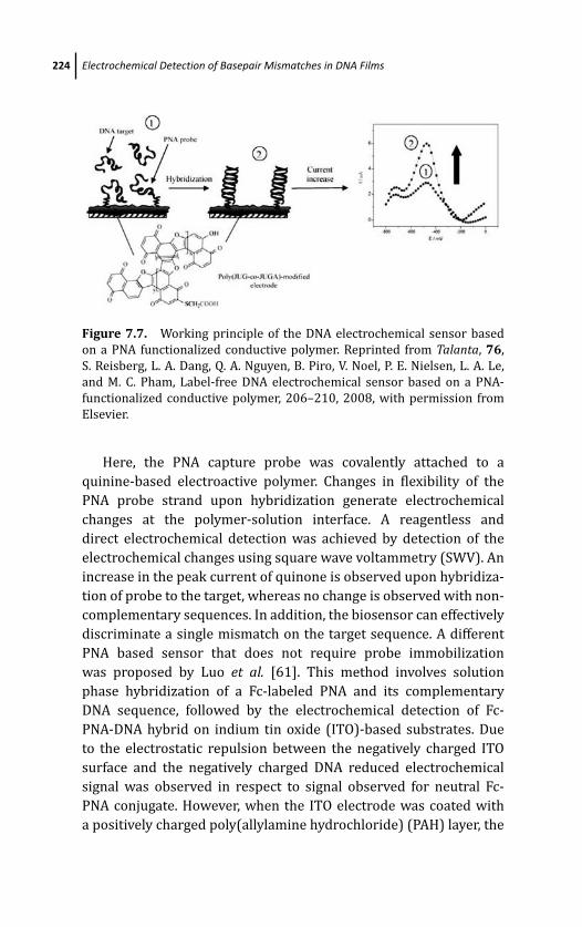
March 19, 2012 17:0 PSP Book - 9in x 6in 07-Ozsoz-c07
224 Electrochemical Detection of Basepair Mismatches in DNA Films
Figure 7.7. Working principle of the DNA electrochemical sensor based
on a PNA functionalized conductive polymer. Reprinted from Talanta, 76,
S. Reisberg, L. A. Dang, Q. A. Nguyen, B. Piro, V. Noel, P. E. Nielsen, L. A. Le,
and M. C. Pham, Label-free DNA electrochemical sensor based on a PNA-
functionalized conductive polymer, 206–210, 2008, with permission from
Elsevier.
Here, the PNA capture probe was covalently attached to a
quinine-based electroactive polymer. Changes in flexibility of the
PNA probe strand upon hybridization generate electrochemical
changes at the polymer-solution interface. A reagentless and
direct electrochemical detection was achieved by detection of the
electrochemical changes using square wave voltammetry (SWV). An
increase in the peak current of quinone is observed upon hybridiza-
tion of probe to the target, whereas no change is observed with non-
complementary sequences. In addition, the biosensor can effectively
discriminate a single mismatch on the target sequence. A different
PNA based sensor that does not require probe immobilization
was proposed by Luo et al. [61]. This method involves solution
phase hybridization of a Fc-labeled PNA and its complementary
DNA sequence, followed by the electrochemical detection of Fc-
PNA-DNA hybrid on indium tin oxide (ITO)-based substrates. Due
to the electrostatic repulsion between the negatively charged ITO
surface and the negatively charged DNA reduced electrochemical
signal was observed in respect to signal observed for neutral Fc-
PNA conjugate. However, when the ITO electrode was coated with
a positively charged poly(allylamine hydrochloride) (PAH) layer, the
March 19, 2012 17:0 PSP Book - 9in x 6in 07-Ozsoz-c07
Detection Strategies 225
electrostatic attraction between the sensor surface and the Fc-PNA-
DNA hybrid caused a significant increase of the electrochemical
signal, which is proportional to the amount of complementary DNA
present. Importantly, the PAH-modified sensor was found to be
more sensitive (with a detection limit of 40 fM) than the bare
ITO substrate (with a detection limit of 500 fM). The method was
further validated by discrimination of fully matched and mismatch
DNA strands at elevated temperatures and detection of unpurified
PCR amplicons with detection limit of 4.17 aM. Recently, a new
strategy was reported that makes use of the minor groove binding of
singly reduced cation radical viologen (V) groups C12VC6VC12 [62].
In the presence of complementary PNA-DNA hybrids, the V 2+/+
redox couple of C12VC6VC12 exhibited a unique double-wave cyclic
voltammogram, with the formal potential shifted by –100 mV from
the E f in the presence of single base mismatched DNA-PNA hybrids
or PNA probes alone.
Without a doubt, unique properties make PNA an interesting,
although sometimes synthetically challenging and expensive, alter-
native for design of biosensors.
7.3.5 Protein Mediated DNA Biosensors
MutS is a 97 kDa protein that is part of the DNA repair “engine”
in E. coli. The protein binds to many of single nucleotide DNA
mismatches and has been used for label-free nucleotide mismatch
detection. There are several reports of utilizing MutS to detect
single nucleotide mismatches by a number of different analytical
tools. However, electrochemical techniques have recently been used
due to inherent sensitivity. It was observed that for alkanethiol-
diluted ds-DNA on gold, the charge transfer resistance Rct increases
considerably after binding of MutS to a A-C mismatch, while no
change in Rct was observed when measuring the electrochemical
impedance of matched DNA duplex in the presence of MutS since the
enzyme does not bind to fully matched ds-DNA (see Fig. 7.8) [63].
Palecek et al. [64] and Masarik et al. [65] detected a G-T
mismatch at CPE and HMDE using chronopotentiometric stripping
analysis (CSA) and squarewave voltammetry (SWV) in the presence
of MutS. Cho et al. [66] found that the binding affinity of MutS for
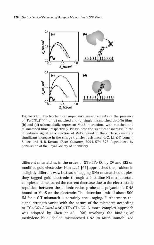
March 19, 2012 17:0 PSP Book - 9in x 6in 07-Ozsoz-c07
226 Electrochemical Detection of Basepair Mismatches in DNA Films
Figure 7.8. Electrochemical impedance measurements in the presence
of [Fe(CN)6]3−/4− of (a) matched and (c) single mismatched ds-DNA films;
(b) and (d) schematically represent MutS interactions with matched and
mismatched films, respectively. Please note the significant increase in the
impedance signal as a function of MutS bound to the surface, causing a
significant increase in the charge transfer resistance. C.-Z. Li, Y.-T. Long, J.
S. Lee, and H.-B. Kraatz, Chem. Commun., 2004, 574–575. Reproduced by
permission of the Royal Society of Chemistry.
different mismatches in the order of GT>CT>CC by CV and EIS on
modified gold electrodes. Han et al. [67] approached the problem in
a slightly different way. Instead of tagging DNA mismatched duplex,
they tagged gold electrode through a histidine-Ni-nitriloacetate
complex and measured the current decrease due to the electrostatic
repulsion between the anionic redox probe and polyanionic DNA
bound to MutS on the electrode. The detection limit of about 500
fM for a G-T mismatch is certainly encouraging. Furthermore, the
signal strength varies with the nature of the mismatch according
to TG>GG>AC=AA=AG>TT>CT>CC. A more complex approach
was adopted by Chen et al. [68] involving the binding of
methylene blue labeled mismatched DNA to MutS immobilized
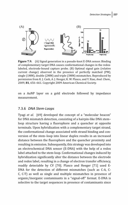
March 19, 2012 17:0 PSP Book - 9in x 6in 07-Ozsoz-c07
Detection Strategies 227
(A) (B)
Figure 7.9. (A) Signal generation in a pseudo-knot E-DNA sensor. Binding
of complementary target DNA causes conformational changes in the redox-
labeled, electrode-bound capture probe. (B) Optimal signal gain (relative
current change) observed in the presence of perfectly matched (PM),
single (1MM), double (2MM) and triple (3MM) mismatches. Reproduced by
permission from K. J. Cash, A. J. Heeger, K. W. Plaxco, and Y. Xiao, Anal. Chem.,2009, 81, 656–661. Copyright 2009 American Chemical Society.
on a AuNP layer on a gold electrode followed by impedance
measurement.
7.3.6 DNA Stem-Loops
Tyagi et al. [69] developed the concept of a “molecular beacon”
for DNA mismatch detection, consisting of a hairpin-like DNA stem–
loop structure having a fluorophore and a quencher at opposite
terminals. Upon hybridization with a complementary target strand,
the conformational change associated with strand binding and con-
version of the stem–loop into linear duplex results in an increased
distance between the fluorophore and the quencher proximity and
resulting in emission. Subsequently, this strategy was developed into
an electrochemical DNA sensor (E-DNA) with the help of a redox
label attached to the stem-loop. Conformational changes induced by
hybridization significantly alter the distance between the electrode
and redox label, resulting in a change of electron transfer efficiency,
readily detectable by CV [70]. Plaxco and Heeger [71] used E-
DNA for the detection of different mismatches (such as C-A, C-
C, C-T) as well as single and multiple mismatches in presence of
organic/inorganic contaminants in a “signal-off” format. E-DNA is
selective to the target sequences in presence of contaminants since
March 19, 2012 17:0 PSP Book - 9in x 6in 07-Ozsoz-c07
228 Electrochemical Detection of Basepair Mismatches in DNA Films
the sensing event depends on the conformational change rather than
on adsorption to the electrode surface.
In addition, it was shown that E-DNA can readily detect single
nucleotide mismatches and can be recycled for the multiple assays.
A “signal-on” type E-DNA sensor based on a pseudo-knot is shown
in Fig. 7.9. In this system, hybridization induced conformational
change brings the redox label close to the electrode surface
and thus enhances electron transfer efficiency [72]. The system
is characterized by the 5’-end being attached to the transducer
surface while the redox-labeled 3’-end forms a pseudo-knot loop
that hybridizes on top of the hairpin loop. The stability of the
pseudo-knot loop at the 3’-terminus depends on the number of
base pairs, which was found to be 7 bp for maximum stability.
The signal response was found to be enhanced twofold with a
more flexible poly(T) loop as compared to poly(A) loop for all
systems investigated, including for fully-matched, single, double and
triple mismatches. The pseudo-knot-based sensor was found to be
selective in presence of serum and sensitive up to 30 pmoles. More
recently, a method was reported based on unlabeled stem loop
structures. Hybridization to the stem loop and opening of the stem
loop will alter the film structure, generally resulting in an increase
in the film thickness.
The charger transfer resistance Rct for electron transfer from
the anionic redox probe [Fe(CN)6]3−/4− through the film will
be greatly influenced by this conformational change. Importantly,
differences in the film caused by the presence of single nucleotide
mismatches are sufficiently large that they cause differences in the
Rct. In particular, the addition of Zn2+ ions amplifies the resistive
differences allowing the detection of single nucleotide mismatches
at concentrations as low as 10 pM [73] (see Fig. 7.10). The effect of
the metal ions is discussed in more detail in the section on metal-ion
amplified sensors.
7.3.6.1 Enzyme-mediated sensors
There are a number of reports of mismatch detection strategies, in
which enzymatic reactions are exploited to amplify the electrochem-
ical signal.
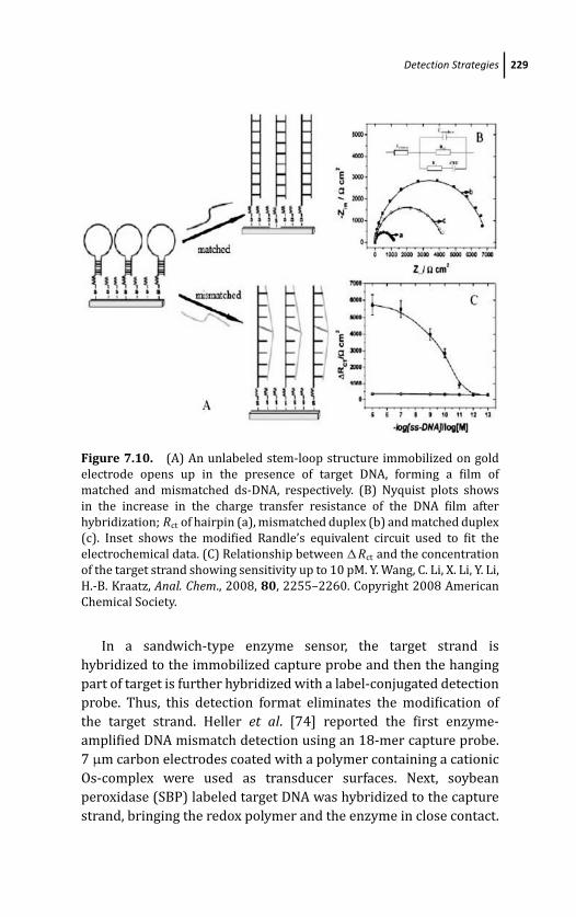
March 19, 2012 17:0 PSP Book - 9in x 6in 07-Ozsoz-c07
Detection Strategies 229
Figure 7.10. (A) An unlabeled stem-loop structure immobilized on gold
electrode opens up in the presence of target DNA, forming a film of
matched and mismatched ds-DNA, respectively. (B) Nyquist plots shows
in the increase in the charge transfer resistance of the DNA film after
hybridization; Rct of hairpin (a), mismatched duplex (b) and matched duplex
(c). Inset shows the modified Randle’s equivalent circuit used to fit the
electrochemical data. (C) Relationship between �Rct and the concentration
of the target strand showing sensitivity up to 10 pM. Y. Wang, C. Li, X. Li, Y. Li,
H.-B. Kraatz, Anal. Chem., 2008, 80, 2255–2260. Copyright 2008 American
Chemical Society.
In a sandwich-type enzyme sensor, the target strand is
hybridized to the immobilized capture probe and then the hanging
part of target is further hybridized with a label-conjugated detection
probe. Thus, this detection format eliminates the modification of
the target strand. Heller et al. [74] reported the first enzyme-
amplified DNA mismatch detection using an 18-mer capture probe.
7 μm carbon electrodes coated with a polymer containing a cationic
Os-complex were used as transducer surfaces. Next, soybean
peroxidase (SBP) labeled target DNA was hybridized to the capture
strand, bringing the redox polymer and the enzyme in close contact.
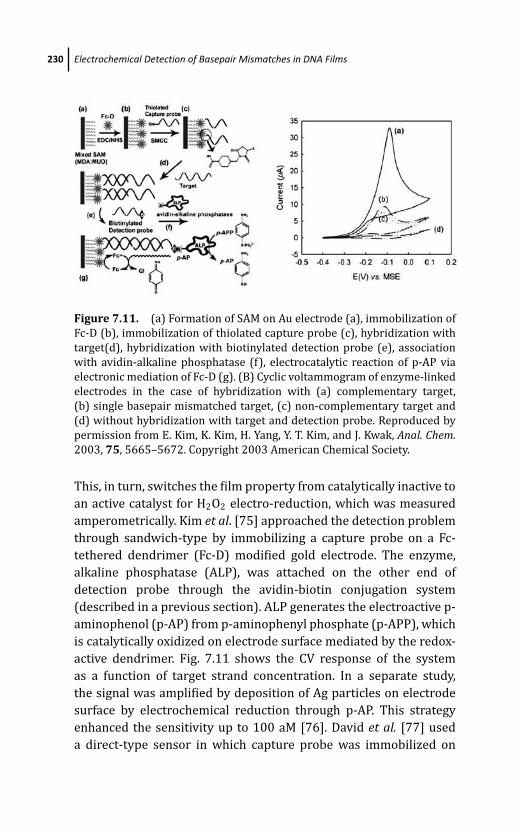
March 19, 2012 17:0 PSP Book - 9in x 6in 07-Ozsoz-c07
230 Electrochemical Detection of Basepair Mismatches in DNA Films
Figure 7.11. (a) Formation of SAM on Au electrode (a), immobilization of
Fc-D (b), immobilization of thiolated capture probe (c), hybridization with
target(d), hybridization with biotinylated detection probe (e), association
with avidin-alkaline phosphatase (f), electrocatalytic reaction of p-AP via
electronic mediation of Fc-D (g). (B) Cyclic voltammogram of enzyme-linked
electrodes in the case of hybridization with (a) complementary target,
(b) single basepair mismatched target, (c) non-complementary target and
(d) without hybridization with target and detection probe. Reproduced by
permission from E. Kim, K. Kim, H. Yang, Y. T. Kim, and J. Kwak, Anal. Chem.2003, 75, 5665–5672. Copyright 2003 American Chemical Society.
This, in turn, switches the film property from catalytically inactive to
an active catalyst for H2O2 electro-reduction, which was measured
amperometrically. Kim et al. [75] approached the detection problem
through sandwich-type by immobilizing a capture probe on a Fc-
tethered dendrimer (Fc-D) modified gold electrode. The enzyme,
alkaline phosphatase (ALP), was attached on the other end of
detection probe through the avidin-biotin conjugation system
(described in a previous section). ALP generates the electroactive p-
aminophenol (p-AP) from p-aminophenyl phosphate (p-APP), which
is catalytically oxidized on electrode surface mediated by the redox-
active dendrimer. Fig. 7.11 shows the CV response of the system
as a function of target strand concentration. In a separate study,
the signal was amplified by deposition of Ag particles on electrode
surface by electrochemical reduction through p-AP. This strategy
enhanced the sensitivity up to 100 aM [76]. David et al. [77] used
a direct-type sensor in which capture probe was immobilized on
March 19, 2012 17:0 PSP Book - 9in x 6in 07-Ozsoz-c07
Detection Strategies 231
a screen-printed carbon electrodes through avidin-biotin coupling
and hybridized with a labeled target strand. Catalytic currents
generated by ALP transformation were quantified voltammetrically
and decreased in case of a base pair mismatch with a sensitivity
up to 0.49 fM. Liu et al. [78] utilized the stem-loop capture
strand, a prototype of E-DNA as discussed above, in which the
capture strand was initially labeled with DIG (digoxigenin) which
was sterically shielded from a bulky horseradish peroxidase (HRP)
due to the particular structural conformation of capture strand. The
hybridization to target DNA makes the DIG accessible to the anti-
DIG-HRP. The successful hybridization event can be easily evaluated
electrochemically. In presence of a single base pair mismatch, the
current is significantly reduced and decreases further in presence of
multiple mismatches. Impedance measurement can be a method of
choice to detect the enzyme-amplified signals because of its inherent
sensitivity [79].
7.3.7 Nanoparticle-Based Sensors
A number of reports appeared in 2001 by Authier and Wang
et al. describing magnetic beads/nanoparticles based electrochem-
ical detection of DNA hybridization using stripping voltammetry
[80, 81]. Magnetic bead based DNA sensors for mismatch detection
circumvents nonspecific adsorption effects of protein, RNA, and non-
complementary oligomers through magnetic separation. Typically,
a prototype magnetic bead based sensor relies on (a) an inosine-
substituted capture probe sequence linked to streptavidin-coated
magnetic particles, (b) hybridization and magnetic removal of non-
hybridized oligonucleotides, (c) alkaline treatment to release the
hybrid from the magnetic particles and denaturing of the duplex,
and finally (d) potentiometric stripping detection of the target
strand’s guanine oxidation peak [81]. This approach can be linked
to enzymatically coupled reactions [82], binding of the metal and
amplified electrochemical detection of the dissolved AuNPs [83],
AgNPs [84], CdSNPs [85], as well as solid state stripping of AgNPs
[86] and multi-target analysis [87] as indicated in Fig. 7.12. This
approach does not give a signal for non-complementary target and
only low signal for a target with single or few mismatches as
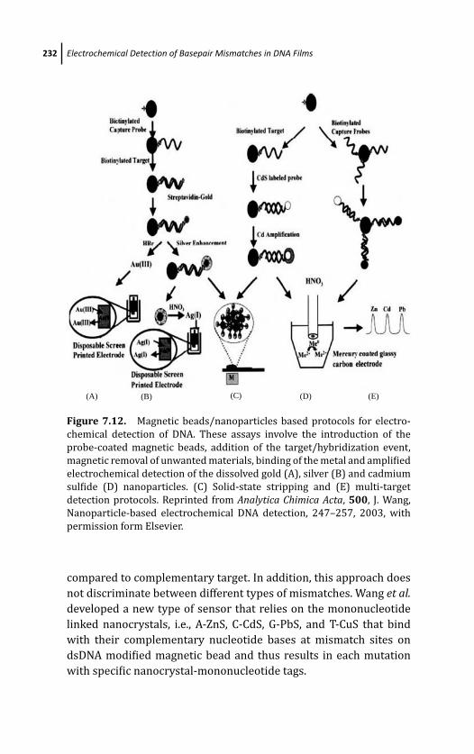
March 19, 2012 17:0 PSP Book - 9in x 6in 07-Ozsoz-c07
232 Electrochemical Detection of Basepair Mismatches in DNA Films
(A) (B) (C) (D) (E)
Figure 7.12. Magnetic beads/nanoparticles based protocols for electro-
chemical detection of DNA. These assays involve the introduction of the
probe-coated magnetic beads, addition of the target/hybridization event,
magnetic removal of unwanted materials, binding of the metal and amplified
electrochemical detection of the dissolved gold (A), silver (B) and cadmium
sulfide (D) nanoparticles. (C) Solid-state stripping and (E) multi-target
detection protocols. Reprinted from Analytica Chimica Acta, 500, J. Wang,
Nanoparticle-based electrochemical DNA detection, 247–257, 2003, with
permission form Elsevier.
compared to complementary target. In addition, this approach does
not discriminate between different types of mismatches. Wang et al.developed a new type of sensor that relies on the mononucleotide
linked nanocrystals, i.e., A-ZnS, C-CdS, G-PbS, and T-CuS that bind
with their complementary nucleotide bases at mismatch sites on
dsDNA modified magnetic bead and thus results in each mutation
with specific nanocrystal-mononucleotide tags.
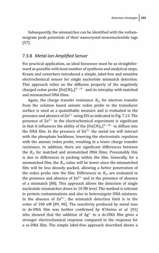
March 19, 2012 17:0 PSP Book - 9in x 6in 07-Ozsoz-c07
Detection Strategies 233
Subsequently, the mismatches can be identified with the voltam-
mogram peak potentials of their nanocrystal-mononucleotide tags
[57].
7.3.8 Metal-Ion Amplified Sensor
For practical application, an ideal biosensor must be as straightfor-
ward as possible with least number of synthesis and analytical steps.
Kraatz and coworkers introduced a simple, label-free and sensitive
electrochemical sensor for single nucleotide mismatch detection.
This approach relies on the diffusive property of the negatively
charged redox probe [Fe(CN)6]3−/4− and its interplay with matched
and mismatched DNA films.
Again, the charge transfer resistance Rct for electron transfer
from the solution based anionic redox probe to the transducer
surface is used as a quantifiable measure and is evaluated in the
presence and absence of Zn2+ using EIS as indicated in Fig. 7.13. The
presence of Zn2+ in the electrochemical experiment is significant
in that it influences the ability of the [Fe(CN)6]3−/4− to diffuse into
the DNA film. In the presence of Zn2+ the metal ion will interact
with the phosphate backbone, lowering the electrostatic repulsion
with the anionic redox probe, resulting in a lower charge transfer
resistance. In addition, there are significant differences between
the Rct for matched and mismatched DNA films. Presumably this
is due to differences in packing within the film. Generally, for a
mismatched film, the Rct value will be lower since the mismatched
film will be less densely packed, allowing a better penetration of
the redox probe into the film. Differences in Rct are evaluated in
the presence and absence of Zn2+ and in the presence of absence
of a mismatch [88]. This approach allows the detection of single
nucleotide mismatches down to 10 fM level. The method is tolerant
to protein contaminations and also to heterozygote DNA mixtures.
In the absence of Zn2+, the mismatch detection limit is in the
order of 100 nM [89, 90]. The sensitivity produced by metal ions
in ds-DNA film was further confirmed by K’Owino et al. [91]
who showed that the addition of Ag+ to a ds-DNA film gives a
stronger electrochemical response compared to the response for
a ss-DNA film. The simple label-free approach described shows a
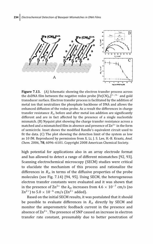
March 19, 2012 17:0 PSP Book - 9in x 6in 07-Ozsoz-c07
234 Electrochemical Detection of Basepair Mismatches in DNA Films
Figure 7.13. (A) Schematic showing the electron transfer process across
the dsDNA film between the negative redox probe [Fe(CN)6]3−/4− and gold
transducer surface. Electron transfer process is facilitated by the addition of
metal ion that neutralizes the phosphate backbone of DNA and allows the
enhanced diffusion of the redox probe. As a result the differences in charge
transfer resistance Rct before and after metal ion addition are significantly
different and are in fact affected by the presence of a single nucleotide
mismatch. (B) Nyquist plot showing the charge transfer resistance across a
matched and a mismatched film in absence and presence of Zn2+ in the form
of semicircle. Inset shows the modified Randle’s equivalent circuit used to
fit the data. (C) The plot showing the detection limit of the system as low
as 10 fM. Reproduced by permission from X. Li, J. S. Lee, H.-B. Kraatz, Anal.Chem. 2006, 78, 6096–6101. Copyright 2008 American Chemical Society.
high potential for applications also in an array electrode format
and has allowed to detect a range of different mismatches [92, 93].
Scanning electrochemical microscopy (SECM) studies were critical
to elucidate the mechanism of this process and rationalize the
differences in Rct in terms of the diffusive properties of the probe
molecules (see Fig. 7.14) [94, 95]. Using SECM, the heterogeneous
electron transfer constants were evaluated and it was shown that
in the presence of Zn2+ the ket increases from 4.6 × 10⁻⁷ cm/s (no
Zn2+) to 5.0 × 10⁻⁶ cm/s (Zn2+ added).
Based on the initial SECM results, it was postulated that it should
be possible to evaluate differences in Rct directly by SECM and
monitor the amperometric feedback current in the presence and
absence of Zn2+. The presence of SNP caused an increase in electron
transfer rate constant, presumably due to better penetration of
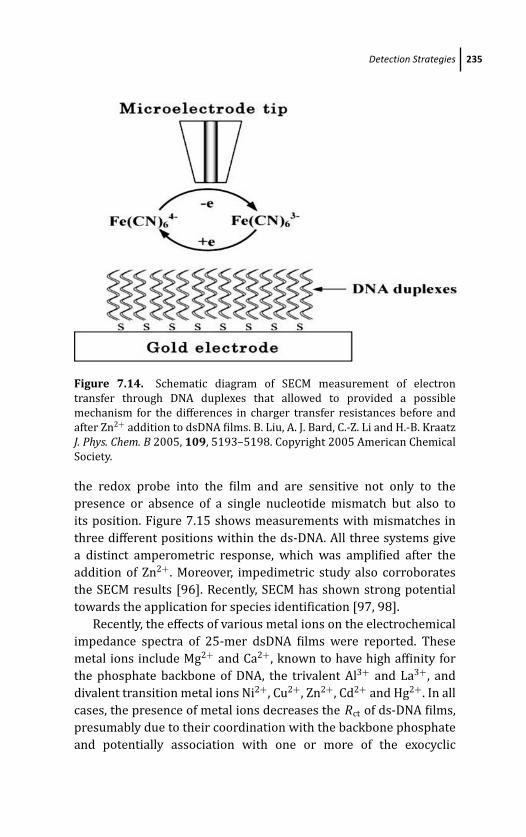
March 19, 2012 17:0 PSP Book - 9in x 6in 07-Ozsoz-c07
Detection Strategies 235
Figure 7.14. Schematic diagram of SECM measurement of electron
transfer through DNA duplexes that allowed to provided a possible
mechanism for the differences in charger transfer resistances before and
after Zn2+ addition to dsDNA films. B. Liu, A. J. Bard, C.-Z. Li and H.-B. Kraatz
J. Phys. Chem. B 2005, 109, 5193–5198. Copyright 2005 American Chemical
Society.
the redox probe into the film and are sensitive not only to the
presence or absence of a single nucleotide mismatch but also to
its position. Figure 7.15 shows measurements with mismatches in
three different positions within the ds-DNA. All three systems give
a distinct amperometric response, which was amplified after the
addition of Zn2+. Moreover, impedimetric study also corroborates
the SECM results [96]. Recently, SECM has shown strong potential
towards the application for species identification [97, 98].
Recently, the effects of various metal ions on the electrochemical
impedance spectra of 25-mer dsDNA films were reported. These
metal ions include Mg2+ and Ca2+, known to have high affinity for
the phosphate backbone of DNA, the trivalent Al3+ and La3+, and
divalent transition metal ions Ni2+, Cu2+, Zn2+, Cd2+ and Hg2+. In all
cases, the presence of metal ions decreases the Rct of ds-DNA films,
presumably due to their coordination with the backbone phosphate
and potentially association with one or more of the exocyclic
March 19, 2012 17:0 PSP Book - 9in x 6in 07-Ozsoz-c07
236 Electrochemical Detection of Basepair Mismatches in DNA Films
Figure 7.15. SECM image with corresponding current profile recorded for
a matched and three different mismatched dsDNA microarrays on a gold
substrate in the absence (a) and presence of of Zn2+ (b). Please note the
differences in the normalized current as a function of mismatch position,
which is enhanced in the presence of Zn2+. P. M. Diakowski, H.-B. Kraatz,
Chem. Commun., 2009, 1189–1191. Reproduced by permission of the Royal
Society of Chemistry.
N -atoms of the purine bases. The �Rct of the different metal ions
was found in the order of Ca2+ > Mg2+ = Hg2+> Cd2+ >Ni2+ >
Cu2+ > Zn2+ which is inversely proportional to their free energies
of hydration (see Fig. 7.16) [99].
7.3.9 Miscellaneous Methods
Recently, Zhu et al. [100] exploited PAMAM dendrimers to tag the
target strand which increase the Rct on hybridization with surface
immobilized capture strand. The �Rct can easily distinguish ds-
DNA without PAMAM tag, mismatched and non-complementary
sequences from PAMAM tagged complementary ds-DNA with
picomolar sensitivity (Fig. 7.17).
Watanabe et al. [101] detected DNA mismatches through a
strand exchange reaction in which the duplex consisting of a
capture probe and a redox-labeled probe strand are immobilized on

March 19, 2012 17:0 PSP Book - 9in x 6in 07-Ozsoz-c07
Detection Strategies 237
Figure 7.16. The relationship between �Rct and free energy of hydration
of divalent metal ions. X. Bin, H.-B. Kraatz, Analyst, 2009, 134, 1309–1313.
Reproduced by permission of the Royal Society of Chemistry.
Figure 7.17. (a) Schematic representation of a gold surface modified with
a ssDNA capture strand followed by hybridization with a ssDNA-PAMAM
target and the formation of dsDNA-dendrimer hybrid; (b) AFM image of
the PAMAM on the mica surface. N. Zhu, H. Gao, Y. Gu, Q. Xu, P. He and
Y. Fang, Analyst, 2009, 134, 860–866. Reproduced by permission of The
Royal Society of Chemistry.
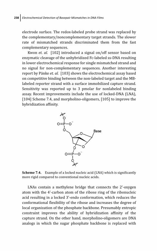
March 19, 2012 17:0 PSP Book - 9in x 6in 07-Ozsoz-c07
238 Electrochemical Detection of Basepair Mismatches in DNA Films
electrode surface. The redox-labeled probe strand was replaced by
the complementary/noncomplementary target strands. The slower
rate of mismatched strands discriminated them from the fast
complementary sequences.
Kwon et. al. [102] introduced a signal on/off sensor based on
enzymatic cleavage of the unhybridized Fc-labeled ss-DNA resulting
in lower electrochemical response for single mismatched strand and
no signal for non-complementary sequences. Another interesting
report by Panke et. al. [103] shows the electrochemical assay based
on competitive binding between the non-labeled target and the MB-
labeled reporter strand with a surface immobilized capture strand.
Sensitivity was reported up to 3 pmolar for nonlabeled binding
assay. Recent improvements include the use of locked-DNA (LNA),
[104] Scheme 7.4, and morpholino-oligomers, [105] to improve the
hybridization affinity.
Scheme 7.4. Example of a locked nucleic acid (LNA) which is significantly
more rigid compared to conventional nucleic acids.
LNAs contain a methylene bridge that connects the 2’-oxygen
atom with the 4’-carbon atom of the ribose ring of the ribonucleic
acid resulting in a locked 3’-endo conformation, which reduces the
conformational flexibility of the ribose and increases the degree of
local organization of the phosphate backbone. Presumably entropic
constraint improves the ability of hybridization affinity of the
capture strand. On the other hand, morpholino-oligomers are DNA
analogs in which the sugar phosphate backbone is replaced with
March 19, 2012 17:0 PSP Book - 9in x 6in 07-Ozsoz-c07
References 239
morpholine rings and bonded through phosphorodiamidate groups,
resulting in an uncharged nucleic acid. These structures are stable,
highly water soluble, and are cost-effective DNA analogs, which
exhibit improved base stacking compared to PNA analogues. The
utility of LNAs for electrochemical sensing of mismatches remains
to be explored but one can envision that the resulting duplex should
exhibit significantly different properties that can be exploited for
sensing.
7.4 Conclusion
Electrochemical detection of DNA mismatches continues to attract
significant attention of the research community. Numerous mis-
match detection schemes have been proposed, some of which even
have led to some limited commercial exploration and start-ups. The
reported detection methods vary widely from relatively simple ones
that exploit the intrinsic electrochemical properties of DNA and
electric properties of the DNA films, to more complex ones that
employ novel bioconjugates, nanopartiocles and DNA analogues.
This growing interest in electrochemical DNA biosensors is often
driven by the unique advantages offered by the electrochemical
detection methods. Application of electrochemical methods in
affinity DNA mismatch detection presents likely a promising
alternative for widely used optical methods, potentially allowing
miniaturization with the associated cost reduction, and potential
application in point-of-care assays. Clearly, the future is promising
for electrochemical DNA sensing and much can be expected in the
next few years.
References
1. K. Sonogashira and Y. T. N. Hagihara, Tetrahedron Lett. 4467 (1975).
2. K. E. Dombrowski, W. Baldwin, and J. E. Sheats, J. Organomet. Chem. 281(1986).
3. A. Okamoto and K. T. I. Saito, Tetrahedron Lett. 4581 (2002).

March 19, 2012 17:0 PSP Book - 9in x 6in 07-Ozsoz-c07
240 Electrochemical Detection of Basepair Mismatches in DNA Films
4. E. Bucci, L. De Napoli, G. Di Fabio, A. Messere, D. Montesar-
chio, A. Romanelli, G. Piccialli, and M. Varra, Tetrahedron 14435(1999).
5. T. Ihara, Y. Maruo, S. Takenaka, and M. Takagi, Nucleic Acids Res. 4273(1996).
6. D. R. van Staveren and N. Metzler-Nolte, Chem. Rev. 5931 (2004).
7. R. C. Mucic, M. K. Herrlein, C. A. Mirkin, and R. L. Letsinger, Chem.Commun. 555 (1996).
8. K. A. Peterlinz and R. M. Georgiadis, J. Am. Chem. Soc. 3401 (1997).
9. K. M. Millan and S. R. Mikkelsen, Anal. Chem. 2317 (1993).
10. S. G. Wang, R. L. Wang, P. J. Sellin, and Q. Zhang, Biochem. Biophys. Res.Commun. 1433 (2004).
11. L. Wu, J. Zhou, J. Luo, and Z. Lin, Electrochim. Acta 2923 (2000).
12. C. B. A. Brett, A. M. O. Brett, and S. H. P. Serrano, J. Electroanal. Chem.Commun. 225 (1994).
13. X. Cai, G. Rivas, P. A. M. Farias, H. Shiraishi, J. Wang, and E. Palecek,
Electroanalysis 753 (1996).
14. X. Lin, S. Zheng, W. Miao, and B. Jin, Anal. Lett. 1373 (2002).
15. D.-W. Pang and H. D. Abruna, Anal. Chem. 3162 (1998).
16. P. M. Armistead and H. H. Thorop, Anal. Chem. 3764 (2000).
17. C. Xu, H. Cai Q. Xu, P. He, and Y. Fang, Fresenius. J. Anal. Chem. 428(2001).
18. M. Wilchek and E. A. Bayer, Anal. Biochem. 1 (1988).
19. S. Tombelli, M. Mascini, and A. P. F. Turner, Biosens. Bioelectron. 929(2002).
20. Y. Okahata M. Kawase, K. Niikura, I. Ohtake, H. Furusawa, and Y. Ebara,
Chem. Commun. 470 (2002).
21. M. Wojciechowski, R. Sundseth, M. Moreno, and R. Henkens, Clin. Chem.1690 (1999).
22. K. Ikebukuro, Y. Kohiki, and K. Sode, Biosens. Bioelectron. 1075 (2002).
23. X. H. Fang, X. J. Liu, S. Schuster, and W. H. Tan, J. Am. Chem. Soc. 2921(1999).
24. A. Dupont-Filliard, A. Roget, T. Livache, and M. Billon, Anal. Chim. Acta449 (2001).
25. E. Palecek, Naturwissenschaften 186 (1958).
26. A. M. Oliveira-Brett, J. A. P. Piedade, L. A. Silva, and V. C. Diculescu, Anal.Biochem. 321–329 (2004).
March 19, 2012 17:0 PSP Book - 9in x 6in 07-Ozsoz-c07
References 241
27. A. M. Oliveira-Brett, V. C. Diculescu, and J. A. P. Piedade, Bioelectrochem-istry 61 (2002).
28. G. Dryhurst, J. Electroanal. Soc. 1411 (1969).
29. J. Wang, G. Rivas, J. R. Fernandes, J. L. Lopez Paz, M. Jiang, and
R. Waymire, Anal. Chim. Acta 197 (1998).
30. M. E. Napier, C. R. Loomis, M. F. Sistare, J. Kim, A. E. Eckhardt, and H. H.
Thorp, Bioconjugate Chem. 906 (1997).
31. H. Wei, Y. Du, J. Kang, and E. Wang, Electrochem. Commun. 1474 (2007).
32. S. O. Kelley, E. M. Boon, J. K. Barton, N. M. Jackson, and M. G. Hill, NucleicAcids Res. 4830 (1999).
33. S. R. Rajski, B. A. Jackson, and J. K. Barton, Mutat. Res. 49 (2000).
34. E. M. Boon and J. K. Barton, Curr. Opin. Struct. Biol. 320 (2002).
35. P. K. Bhattacharya and J. K. Barton, J. Am. Chem. Soc. 8649 (2001).
36. L. P. J. Marques, I. Cavaco, J. P. Pinheiro, V. Ribeiro, and G. N. M. Ferreira,
Clin. Chem. Lab. Med. 475 (2003).
37. A. K. Boal and J. K. Barton, Bioconjugate Chem. 312 (2005).
38. M. Inouye, R. Ikeda, M. Takase, T. Tsuri, and J. Chiba, Proc. Natl. Acad.Sci. U.S.A. 11606 (2005).
39. R. Ikeda, J. Chiba, and M. Inouye, e-J. Surf. Sci. Nanotechnol. 393 (2005).
40. E. L. S. Wong and J. J. Gooding, Anal. Chem. 2138 (2006).
41. A. A. Gorodetsky and J. K. Barton, Langmuir 7917 (2006).
42. A. A. Gorodetsky and J. K. Barton, J. Am. Chem. Soc. 6074 (2007).
43. K. Yamashita, M. Takagi, H. Kondo, and S. Takenaka, Anal. Biochem. 188(2002).
44. X. Lin, S. Zheng, Q. Miao, and B. Jin, Anal. Lett. 1373 (2002).
45. P. Kara, B. Meric, A. Zeytinoglu, and M. Ozsoz, Anal. Chim. Acta 69(2004).
46. V. Ostatna, N. Dolinnaya, S. Andreev, T. Oretskaya, J. Wang,. and
T. Hianik, Bioelectrochemistry. 205 (2005).
47. K.-J. Feng, Y.-H. Yang, Z.-J. Wang, J.-H. Jiang, G.-L. Shen, and R.-Q. Yu,
Talanta 561 (2006).
48. T. Garcia, M. Revenga-Parra, H. D. Abruna, F. Pariente, and E. Lorenzo,
Anal. Chem. 77 (2008).
49. S. Niu, M. Wu, S. Bi, and S. Zhang, Bioelectrochemistry 64 (2008).
50. X. Wei, Q. Hao, Q. Zhou, J. Wu, L. Lu, X. Wang, and X. Yang, Electrochim.Acta 7338 (2008).
51. X.-M. Li, H.-Q. Ju, C.-F, Ding, and S.-S. Zhang, Ana. Chim. Acta 158 (2007).
March 19, 2012 17:0 PSP Book - 9in x 6in 07-Ozsoz-c07
242 Electrochemical Detection of Basepair Mismatches in DNA Films
52. P. E. Nielsen, M. Egholm, R. H. Berg, and O. Buchardt, Science 1497(1991).
53. E. Uhlmann, A. Peyman, G. Breipohl, and W. W. David, Angew. Chem. Int.Ed, 2796 (1998).
54. S. Tomac, M. Sarkar, T. Ratilainen, P. Wittung, P. E. Nielsen, B. Norden,
and A. Graslund, J. Am. Chem. Soc. 5544 (1996).
55. J. Wang, E. Palecek, P. E. Nielsen, G. Rivas, X. Cai, H. Shiraishi, N. Dontha,
D. Luo, and P. A. M.Farias, J. Am. Chem. Soc. 7667 (1996).
56. H. Aoki, P. Buhlmann, and Y. Umezawa, Electroanalysis 1272 (2000).
57. G. Liu, T. M. Lee, and J.Wang, J. Am. Chem. Soc. 38 (2005).
58. K. Hashimoto and Y. Ishimori, Lab Chip 61 (2001).
59. B. Fang, S. Jiao, M. Li, Y. Qu, and X. Jiang, Biosens. Bioelectron. 1175(2008).
60. S. Reisberg, L. A. Dang, Q. A. Nguyen, B. Piro, V. Noel, P. E. Nielsen, L. A.
Le, and M. C. Pham, Talanta 206 (2008).
61. X. Luo, T. M.-H. Lee, and I. M. Hsing, Anal. Chem. 7341 (2008).
62. E. G. Hvastkovs and D. A. Buttry, Langmuir, 3839 (2009).
63. C. Z. Li, Y. T. Long, J. S. Lee, and H.-B. Kraatz, Chem. Commun. 574 (2004).
64. E. Palecek, M. Masarik, R. Kizek, D. Kuhlmeier, J. Hassmann, and
J. Schulein, Anal. Chem. 5930 (2004).
65. M. Masarik, K. Cahova, R. Kizek, E. Palecek, and M. Fojta, Anal. Bioanal.Chem. 259 (2007).
66. M. Cho, S. Lee, S.-Y. Han, J.-Y. Park, M. A. Rahman, Y.-B. Shim, and C. Ban,
Nucleic Acids Res. (2006).
67. A. S. Han, T. Takarada, T. Shibata, M. Nakayama, and M. Maeda, Anal. Sci.663 (2006).
68. H. Chen, X. J. Liu, Y. L. Liu, J. H. Jiang, G. L. Shen, and R. Q. Yu, Biosens.Bioelectron. 1955 (2009).
69. S. Tyagi and F. R. Kramer, Nat. Biotechnol. 303 (1996).
70. C. H. Fan, K. W. Plaxco, and A. J. Heeger, Proc. Natl. Acad. Sci. U.S.A. 9134(2003).
71. A. A. Lubin, R. Y. Lai, B. R. Baker, A. J. Heeger, and K. W. Plaxco, Anal.Chem. 5671 (2006).
72. K. J. Cash, A. J. Heeger, K. W. Plaxco, and Y. Xiao, Anal. Chem. 656 (2009).
73. Y. Wang, C. J. Li, X. H. Li, Y. F. Li, and H.-B. Kraatz, Anal. Chem. 2255(2008).
74. D. J. Caruana and A. Heller, J. Am. Chem. Soc. 4728 (1999).
March 19, 2012 17:0 PSP Book - 9in x 6in 07-Ozsoz-c07
References 243
75. D. Hernandez-Santos, M. Diaz-Gonzalez, M. B. Gonzalez-Garcia, and
A. Costa-Garcia, Anal. Chem. 6887 (2004).
76. E. Kim, K. Kim, H. Yang, Y. T. Kim, and J. Kwak, Anal. Chem. 5665 (2003).
77. S. Hwang, E. Kim, and J. Kwak, Anal. Chem. 579 (2005).
78. G. Liu, Y. Wan, V. Gau, J. Zhang, L. H. Wang, S. P. Song, and C. H. Fan, J. Am.Chem. Soc. 6820 (2008).
79. L. Tang, G. M. Zeng, G. L. Shen, Y. P. Li, C. Liu, Z. Li, J. Luo, C. Z. Fan, and
C. P. Yang, Biosens. Bioelectron. 1474 (2009).
80. L. Authier, C. Grossiord, and P. Brossier, Anal. Chem. 4450 (2001).
81. J. Wang, A. N. Kawde, A. Erdem, and M. Salazar, Analyst 2020 (2001).
82. J. Wang, D. Xu, A. Erdem, R. Polsky, and M. A. Salazar, Talanta 931(2002).
83. J. Wang, D. Xu, A. N. Kawde, and R. Polsky, Anal. Chem. 5576 (2001).
84. J. Wang, R. Polsky, and D. Xu, Langmuir 5739 (2001).
85. J. Wang, G. Liu, R. Polsky, and A. Merkoci, Electrochem. Commun. 722(2002).
86. J. Wang, D. Xu, and R. Polsky, J. Am. Chem. Soc. 4208 (2002).
87. J. Wang, G. Liu, and A. Merkoci, J. Am. Chem. Soc. 3214 (2003).
88. Y. T. Long, C. Z. Li, H.-B. Kraatz, and J. S. Lee, Biophys. J. 3218 (2003).
89. T. Ito, K. Hosokawa, and M. Maeda, Biosens. Bioelectron. 1816 (2007).
90. J. Kafka, O. Panke, B. Abendroth, and F. Lisdat, Electrochim. Acta 7467(2008).
91. I. O. K’Owino, S. K. Mwilu, and O. A. Sadik, Anal. Biochem. 8 (2007).
92. X. Li, J. S. Lee, and H.-B. Kraatz, Anal. Chem. 6096 (2006).
93. X. Li, Y. Zhou, T. C. Sutherland, B. Baker, J. S. Lee, and H.-B. Kraatz, Anal.Chem. 5766 (2005).
94. P. M. Diakowski and H.-B. Kraatz, Chem. Commun. 1189 (2009).
95. B. Liu, A. J. Bard, C. Z. Li, and H.-B. Kraatz, J. Phys. Chem. B 5193 (2005).
96. M. H. Shamsi and H.-B. Kraatz, Analyst 2280 (2010).
97. P. M. Diakowski and H.-B. Kraatz, Chem. Commun. 1431 (2011).
98. M. H. Shamsi and H.-B. Kraatz, Analyst (2011) DOI:
10.1039/C1AN15414A.
99. X. Bin and H.-B. Kraatz, Analyst 1309 (2009).
100. N. Zhu, H. Gao, Y. Gu, Q. Xu, P. He, and Y. Fang, Analyst 860 (2009).
101. M. Watanabe, S. Kumamoto, M. Nakamaura, and K. Yamana, Bioorg.Med. Chem. 1494 (2009).

March 19, 2012 17:0 PSP Book - 9in x 6in 07-Ozsoz-c07
244 Electrochemical Detection of Basepair Mismatches in DNA Films
102. D. Kwon, K. Kim, and J. Kwaka, Electroanalysis 1204 (2008).
103. O. Panke, A. Kirbs, and F. Lisdat, Biosens. Bioelectron. 2656 (2007).
104. J. Chen, J. Zhang, K. Wang, X. Lin, L. Huang, and G. Chen, Anal. Chem.8028 (2008).
105. Z. Gao and B. P. Ting, Analyst 952 (2009).
March 19, 2012 17:1 PSP Book - 9in x 6in 08-Ozsoz-c08
Chapter 8
Electrochemical Detection of DNAHybridization: Use of Latex to ConstructMetal-Nanoparticle Labels
Mithran Somasundruma and Werasak Surareungchaib
aBiochemical Engineering and Pilot Plant Research and Development Unit,National Center for Genetic Engineering and Biotechnology atKing Mongkut’s University of Technology, Thonburi,Bangkhuntien Campus, Bangkok 10150, ThailandbSchool of Bioresources and Technology, King Mongkut’s University of Technology,Thonburi, Bangkhuntien Campus, Bangkok 10150, [email protected]
8.1 Introduction
Of the detection schemes available for DNA biosensors [1], elec-
trochemistry has drawn increasing interest due to enabling high
sensitivities using equipment of relatively low cost. In addition,
electrochemical detection can be coupled readily with available
minaturization technologies [2]. The direct electro-oxidation of
guanine involves high background signals [3], while the use of
enzyme labels may involve deterioration of enzyme activity over
time. Redox compounds which can intercalate with the probe-target
Electrochemical DNA BiosensorsEdited by Mehmet OzsozCopyright c© 2012 Pan Stanford Publishing Pte. Ltd.ISBN 978-981-4241-77-9 (Hardcover), 978-981-4303-98-9 (eBook)www.panstanford.com
March 19, 2012 17:1 PSP Book - 9in x 6in 08-Ozsoz-c08
246 Electrochemical Detection of DNA Hybridization
duplex can provide a more stable signal [4] but do not always
provide adequate sensitivity. This has led to interest in using
metal nanoparticles as labels for electrochemical detection of DNA
hybridization (reviewed in Refs. 5–7).
Where the nanoparticles are reacted directly (rather than being
used to catalyze reactions), the achievable sensitivity will depend
largely on the quantity of metal attached to each DNA sequence.
This has led to the development in label construction illustrated in
Fig. 8.1. From the binding of individual particles, researchers have
sought techniques to attach assemblies of nanoparticles to a given
DNA sequence. As will be described in this chapter, latex colloids
provide an ideal base for such assemblies, both as solid supports
and as templates for the construction of hollow capsules which can
take up nanomaterials. The point of importance is that the necessary
latex modifications have already been intensively researched for
other applications, and so the relevant physical chemistry theory
and experimental details are already available. Despite this fact, the
use of latex in constructing electrochemical DNA labels is relatively
unexplored.
8.2 Synthesis of Metal Nanoparticles
Colloidal gold was first prepared and studied by Faraday in 1857 [8].
In the early 1950s, the preparation of colloidal gold in homogeneous
solution was described by Turkevich et al. [9] using sodium citrate
to reduce a dilute solution of HAuCl4 under heating. This method
has become a standard for gold nanoparticle preparation and has
also been applied for the synthesis of platinum nanoparticles by
the reduction of PtCl62− [10]. Similar homogeneous synthesis can
be performed for silver nanoparticles, using NaBH4 as a reducing
agent for AgNO3 [11]. When the nanoparticles are formed there
needs to be a force resisting coagulation present for the particles to
remain stable in solution. This force can be provided by electrostatic
repulsion due to the adsorption of ions onto the metal surface and
in some cases the adsorption of the reducing agent (e.g., when
AuCl4− is reduced by citrate the citrate ions remain adsorbed on
the particles and impart a negative charge [12]). The electrostatic
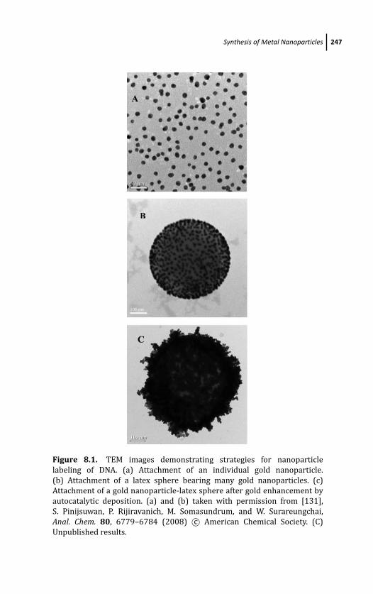
March 19, 2012 17:1 PSP Book - 9in x 6in 08-Ozsoz-c08
Synthesis of Metal Nanoparticles 247
Figure 8.1. TEM images demonstrating strategies for nanoparticle
labeling of DNA. (a) Attachment of an individual gold nanoparticle.
(b) Attachment of a latex sphere bearing many gold nanoparticles. (c)
Attachment of a gold nanoparticle-latex sphere after gold enhancement by
autocatalytic deposition. (a) and (b) taken with permission from [131],
S. Pinijsuwan, P. Rijiravanich, M. Somasundrum, and W. Surareungchai,
Anal. Chem. 80, 6779–6784 (2008) c© American Chemical Society. (C)
Unpublished results.
March 19, 2012 17:1 PSP Book - 9in x 6in 08-Ozsoz-c08
248 Electrochemical Detection of DNA Hybridization
stabilization can be added to by steric factors. If a polymer layer is
adsorbed on the particle or tethered to the particle at one end, then
this will further limit the inter-particle approach [13]. Examples of
polymeric stabilizers include polyvinyl alcohol (PVA) and sodium
polyacrylate. Typically the stabilizer is present during the metal-ion
reduction, and this means it can have an effect on the growth process
of the particle. Strong polymer adsorption will slow the growth
rate. Stabilizers can also have a catalytic effect on the reaction
[10]. In some cases a variation in the stabilizer concentration
can change the nanoparticle shape [14]. With regard to gold
nanoparticles, the synthesis can be performed and then long-chain
molecules get attached to the gold by a thiol terminus [15–16]. The
polymer stabilizer can also be provided by performing the reaction
in a water-in-oil (w/o) microemulsion. This is done by reacting
reverse micelles containing a metal salt with reverse micelles
containing reducing agent [17–20]. Mixing the two microemulsions
causes an exchange of material between the micelles. The reaction
occurs first at the edges of the micelle (the initial locus of the
reaction) and then moves into the centre, as demonstrated by
TEM studies [21]. Nanoparticles can also be synthesized from
a single microemulsion, usually containing the metal salt, while
adding the reducing agent directly to the mixture [22–23]. The
principle of microemulsion synthesis has been extended to water-
in-supercritical CO2 microemulsions, the rationale being that the
nanomaterial can be simply recovered by reducing the pressure and
releasing the resulting gas. Silver [24] and copper nanoparticles [25]
have been reported.
In general terms, if the rate of growth of the nanoparticles
is high relative to the rate of nucleation (i.e., the rate of new
particles forming), then the resulting materials will have a narrow
size distribution. This is highly desirable if the particles are to
be used as electrochemical labels, since the size distribution will
affect the precision of the resulting sensor. The rate of the reaction
can be influenced by the nature and concentration of the reducing
agent, with strong reducing agents favoring a faster reaction rate
and smaller nanoparticles [13]. Note however, that an overall fast
reaction does not necessarily imply a faster rate of growth relative
to nucleation.
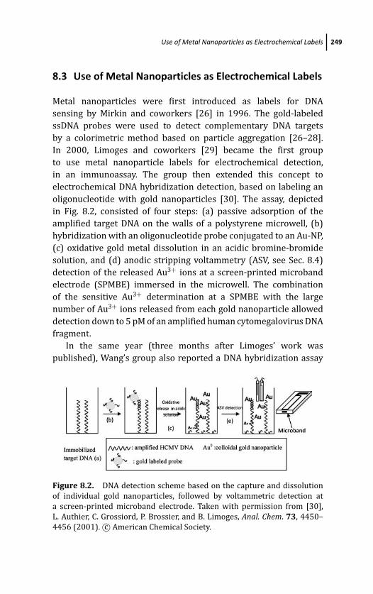
March 19, 2012 17:1 PSP Book - 9in x 6in 08-Ozsoz-c08
Use of Metal Nanoparticles as Electrochemical Labels 249
8.3 Use of Metal Nanoparticles as Electrochemical Labels
Metal nanoparticles were first introduced as labels for DNA
sensing by Mirkin and coworkers [26] in 1996. The gold-labeled
ssDNA probes were used to detect complementary DNA targets
by a colorimetric method based on particle aggregation [26–28].
In 2000, Limoges and coworkers [29] became the first group
to use metal nanoparticle labels for electrochemical detection,
in an immunoassay. The group then extended this concept to
electrochemical DNA hybridization detection, based on labeling an
oligonucleotide with gold nanoparticles [30]. The assay, depicted
in Fig. 8.2, consisted of four steps: (a) passive adsorption of the
amplified target DNA on the walls of a polystyrene microwell, (b)
hybridization with an oligonucleotide probe conjugated to an Au-NP,
(c) oxidative gold metal dissolution in an acidic bromine-bromide
solution, and (d) anodic stripping voltammetry (ASV, see Sec. 8.4)
detection of the released Au3+ ions at a screen-printed microband
electrode (SPMBE) immersed in the microwell. The combination
of the sensitive Au3+ determination at a SPMBE with the large
number of Au3+ ions released from each gold nanoparticle allowed
detection down to 5 pM of an amplified human cytomegalovirus DNA
fragment.
In the same year (three months after Limoges’ work was
published), Wang’s group also reported a DNA hybridization assay
Figure 8.2. DNA detection scheme based on the capture and dissolution
of individual gold nanoparticles, followed by voltammetric detection at
a screen-printed microband electrode. Taken with permission from [30],
L. Authier, C. Grossiord, P. Brossier, and B. Limoges, Anal. Chem. 73, 4450–
4456 (2001). c© American Chemical Society.
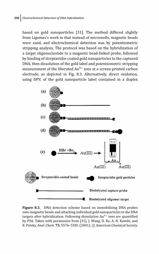
March 19, 2012 17:1 PSP Book - 9in x 6in 08-Ozsoz-c08
250 Electrochemical Detection of DNA Hybridization
based on gold nanoparticles [31]. The method differed slightly
from Ligomes’s work in that instead of microwells, magnetic beads
were used, and electrochemical detection was by potentiometric
stripping analysis. The protocol was based on the hybridization of
a target oligonucleotide to a magnetic bead-linked probe, followed
by binding of streptavidin-coated gold nanoparticles to the captured
DNA, then dissolution of the gold label and potentiometric stripping
measurement of the liberated Au3+ ions at a screen-printed carbon
electrode, as depicted in Fig. 8.3. Alternatively, direct oxidation,
using DPV, of the gold nanoparticle label contained in a duplex
Figure 8.3. DNA detection scheme based on immobilizing DNA probes
onto magnetic beads and attaching individual gold nanoparticles to the DNA
targets after hybridization. Following dissolution Au3+ ions are quantified
by PSA. Taken with permission from [31], J. Wang, D. Xu, A.-N. Kawde, and
R. Polsky, Anal. Chem. 73, 5576–5581 (2001). c© American Chemical Society.
March 19, 2012 17:1 PSP Book - 9in x 6in 08-Ozsoz-c08
Use of Metal Nanoparticles as Electrochemical Labels 251
attached to a graphite pencil electrode surface was used by Ozsoz
et al. [32]. Fang and coworkers [33] have reported the use of silver
nanoparticles (AgNP) as the oligonucleotide label. By oxidative
metal dissolution and the indirect determination of the solubilized
Ag+ by ASV at a carbon fiber microelectrode, detection down
to 0.5 pM DNA was reported. The same group has also labeled
oligonucleotide probes with an alloy of gold-coated copper core-
shell nanoparticles for a DNA sensing assay [34]. Hybridization
events between probe and target were monitored by the release
of the copper metal atoms anchored on the hybrids by oxidative
metal dissolution, and then indirect determination of the solubilized
Cu2+ ions by ASV. Despite the good sensitivity of all the above
reports, detection limits remained in the range of nanomolar to
subpicomolar (see Table 8.1). Further improvements are needed
to meet the challenge of detecting as low as hundreds of copies
of target DNA—required to avoid using pre-amplification schemes
such as the polymerase chain reaction.
Since the analytical signal in ASV comes from consumption
of the metal film deposited on the electrode (see Sec. 8.4), the
signal can be increased by increasing the size of the nanoparticle.
However, large diameters (e.g., for gold greater than about 20 nm)
are seldom used as electrochemical labels due to reasons such as
poor control of size distribution and poor stability in a solution
of the resulting bioconjugates, causing lower hybridization rates.
A preferable method has been to use smaller nanoparticles, and
then, after hybridization, increase the quantity of the metal by
forming shells of gold or silver on the original nanoparticle through
autocatalytic reduction. Silver deposition has been commonly used
in histochemical microscopy to visualize DNA-conjugated gold
nanoparticles. Based on this concept, Mirkin and coworkers [35]
developed a scanometric DNA array based on silver amplification
of the hybridization event. Wang and coworkers [36] extended this
form of amplification to electrochemical detection by measuring the
deposited silver by stripping analysis. Basically, after hybridization
gold nanoparticles function as catalytic sites for chemical reduction
of silver ions (from silver lactate or silver nitrate) in the presence of
the reducing agent, hydroquinone. Hence, metallic silver is formed
on the gold nanoparticles. This was detected at a screen-printed
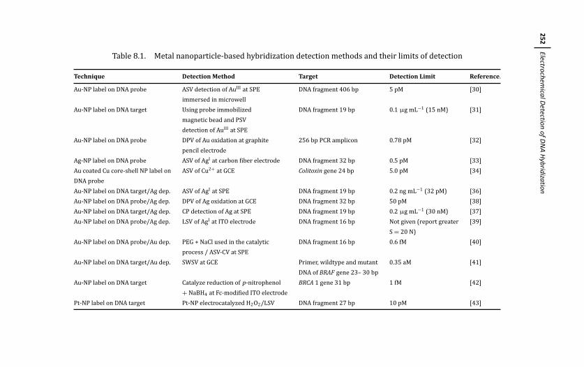
March
19,201217:1
PSPBook
-9inx
6in08-O
zsoz-c08
252Electrochem
icalDetection
ofDN
AH
ybridization
Table 8.1. Metal nanoparticle-based hybridization detection methods and their limits of detection
Technique Detection Method Target Detection Limit Reference.
Au-NP label on DNA probe ASV detection of AuIII at SPE DNA fragment 406 bp 5 pM [30]
immersed in microwell
Au-NP label on DNA target Using probe immobilized DNA fragment 19 bp 0.1 μg mL−1 (15 nM) [31]
magnetic bead and PSV
detection of AuIII at SPE
Au-NP label on DNA probe DPV of Au oxidation at graphite 256 bp PCR amplicon 0.78 pM [32]
pencil electrode
Ag-NP label on DNA probe ASV of AgI at carbon fiber electrode DNA fragment 32 bp 0.5 pM [33]
Au coated Cu core-shell NP label on ASV of Cu2+ at GCE Colitoxin gene 24 bp 5.0 pM [34]
DNA probe
Au-NP label on DNA target/Ag dep. ASV of AgI at SPE DNA fragment 19 bp 0.2 ng mL−1 (32 pM) [36]
Au-NP label on DNA probe/Ag dep. DPV of Ag oxidation at GCE DNA fragment 32 bp 50 pM [38]
Au-NP label on DNA target/Ag dep. CP detection of Ag at SPE DNA fragment 19 bp 0.2 μg mL−1 (30 nM) [37]
Au-NP label on DNA probe/Ag dep. LSV of AgI at ITO electrode DNA fragment 16 bp Not given (report greater [39]
S = 20 N)
Au-NP label on DNA probe/Au dep. PEG + NaCl used in the catalytic DNA fragment 16 bp 0.6 fM [40]
process / ASV-CV at SPE
Au-NP label on DNA target/Au dep. SWSV at GCE Primer, wildtype and mutant 0.35 aM [41]
DNA of BRAF gene 23– 30 bp
Au-NP label on DNA target Catalyze reduction of p-nitrophenol BRCA 1 gene 31 bp 1 fM [42]
+ NaBH4 at Fc-modified ITO electrode
Pt-NP label on DNA target Pt-NP electrocatalyzed H2O2/LSV DNA fragment 27 bp 10 pM [43]
March 19, 2012 17:1 PSP Book - 9in x 6in 08-Ozsoz-c08
Use of Metal Nanoparticles as Electrochemical Labels 253
carbon electrode using potentiometric stripping voltammetry after
acid dissolution. However, excess silver ions are of major concern
in this method, as they can affect the reliability of the stripping-
based detection. This is because the polyanionic DNA backbone
itself can act as a nucleation site for silver deposition following
cation exchange with sodium for ion-pair complexation to the DNA
bases, which can lead to a high background. To obviate this problem,
sodium thiosulfate can be used as a fixer [it transfers the silver
cations to [Ag(S2O3)]5−]. Control of the silver precipitation time
is also needed. Silver-enhanced colloidal gold stripping led to a
dramatic (>100 fold) signal amplification. Instead of dissolving the
silver for stripping analysis, a direct assay of the silver metal can
also be performed by either constant-current chronopotentiometric
detection after magnetic collection of the duplex-linked particle
assembly [37], or a differential pulse voltammetry measurement
of the large number of silver atoms anchored on the duplexes,
using a glassy carbon electrode [38]. Lee et al. [39] reported the
catalytic effects of various gold nanoparticles for silver deposition
on indiumtin oxide (ITO)based electrodes.
The use of silver enhancement may cause a significant back-
ground signal due to non-specific silver deposition on the DNA
support (i.e., the magnetic bead or electrode surface) and/or on
the negatively charged DNA (as mentioned above). Hence, Rochelet-
Dequaire et al. [40] instead used gold ions for the catalytic enhance-
ment, since the gold autocatalytic process offers a lower background.
This is because there is minimal autonucleation from AuCl4− and
less interaction between the anionic AuCl4− and the negatively
charged DNA. Their work showed that classical gold enhancement
procedures based on incubation in a mixture of chloroauric acid
and hydroxylamine could not provide effective amplification, due to
loss of the enhanced gold labels during the post-enlargement rinsing
step. Therefore, the authors modified the enhancement procedure
to use polyethylene glycol and NaCl in the growth media, to act as
an aggregating agent during the catalytic process. This resulted in
retention of the enlarged labels on the bottom of the microwell,
providing a detection limit of 0.6 fM. Liao et al. [41] reported
a similar scheme by using a square wave stripping voltammetry
and were able to detect a mutated BRAF gene associated with
March 19, 2012 17:1 PSP Book - 9in x 6in 08-Ozsoz-c08
254 Electrochemical Detection of DNA Hybridization
papillary thyroid carcinomas at a detection limit of 0.35 aM.
Selvaraju et al. [42] realized a drawback of the gold autocatalytic
process is that special care is required in the control of deposition
time and temperature to achieve a high signal-to-background ratio
Instead, they used DNA-labeled gold nanoparticles to catalyze the
reduction of p-nitrophenol to electroactive p-aminophenol. The
p-aminophenol can be catalytically cycled back to p-nitrophenol
at a ferrocene-modified indium-tin oxide (ITO) electrode, offering
large signal amplification. The high signal amplification and low
background current enabled the detection of 1 fM target DNA.
Willner’s group has used platinum-nanoparticle labeled DNA where
the nanoparticles catalyzed the reduction of H2O2 with a detection
limit of 10 pM for the hybridization [43].
8.4 Voltammetric Detection of Metal-Nanoparticle Labels
Voltammetry is of interest as a detection method for DNA due to
the fact that it provides high sensitivities and that the equipment
required is relatively cheap in comparison with techniques such
as fluorescence, surface plasmon resonance, and microfabricated
cantilevers, while safety issues exist with radioactive labels. Below
we summarize the voltammetry theory necessary to develop and
test DNA sensors.
8.4.1 Principles of Analytical Voltammetry
The principle of analytical voltammetry is that the current I from a
redox reaction is recorded under conditions of controlled potential
and is used to calibrate the concentration of the reacting species.
The electrode potential is set relative to a reference interface
which ideally does not change potential as the voltage applied
across the cell is changed. To exhibit this property the current
across the interface during equilibrium should be high. Common
reference interfaces are Ag/AgCl/KClsat and Hg/Hg2Cl2/KClsat. To
complete the current path for the reaction a third electrode is usually
incorporated, but two-electrode cells can also be used by passing
current through the reference, provided that current is in the order
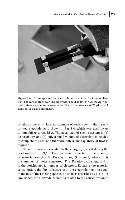
March 19, 2012 17:1 PSP Book - 9in x 6in 08-Ozsoz-c08
Voltammetric Detection of Metal-Nanoparticle Labels 255
Figure 8.4. Screen-printed two electrode cell used for ssDNA immobiliza-
tion. The carbon track working electrode is held at 100 mV vs. the Ag/AgCl
track reference/counter electrode for 30 s in the presence of 20 μL ssDNA
solution. See also Color Insert.
of microamperes or less. An example of such a cell is the screen-
printed electrode strip shown in Fig. 8.4, which was used by us
to immobilize target DNA. The advantage of such a system is (a)
disposability, and (b) only a small volume of electrolyte is needed
to complete the cell, and therefore only a small quantity of DNA is
required.
The redox current is related to the charge Q passed during the
reaction by I = dQ /dt. That charge is connected to the quantity
of material reacting by Faraday’s law, Q = mnF, where m is
the number of moles converted, F is Faraday’s constant, and nis the stoichiometric number of electrons. Equating the material
consumption, the flux of electrons at the electrode must be equal
to the flux of the reacting species. This flux is described by Fick’s 1st
law. Hence, the electrode current is related to the concentration of
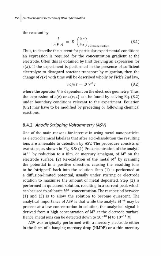
March 19, 2012 17:1 PSP Book - 9in x 6in 08-Ozsoz-c08
256 Electrochemical Detection of DNA Hybridization
the reactant by
In F A
= D(
∂ c∂ x
)
electrode surface
(8.1)
Thus, to describe the current for particular experimental conditions
an expression is required for the concentration gradient at the
electrode. Often this is obtained by first deriving an expression for
c(x). If the experiment is performed in the presence of sufficient
electrolyte to disregard reactant transport by migration, then the
change of c(x) with time will be described wholly by Fick’s 2nd law,
∂ c/∂ t = D ∇2 c (8.2)
where the operator ∇ is dependent on the electrode geometry. Thus,
the expression of c(x) or c(x , t) can be found by solving Eq. (8.2)
under boundary conditions relevant to the experiment. Equation
(8.2) may have to be modified by preceding or following chemical
reactions.
8.4.2 Anodic Stripping Voltammetry (ASV)
One of the main reasons for interest in using metal nanoparticles
as electrochemical labels is that after acid-dissolution the resulting
ions are amenable to detection by ASV. The procedure consists of
two steps, as shown in Fig. 8.5: (1) Preconcentration of the analyte
M n+ by reduction to a film, or mercury amalgam, of M0 on the
electrode surface. (2) Re-oxidation of the metal M0 by scanning
the potential in a positive direction, causing the resulting ions
to be “stripped” back into the solution. Step (1) is performed at
a diffusion-limited potential, usually under stirring or electrode
rotation to maximize the amount of metal deposited. Step (2) is
performed in quiescent solution, resulting in a current peak which
can be used to calibrate M n+ concentration. The rest period between
(1) and (2) is to allow the solution to become quiescent. The
analytical importance of ASV is that while the analyte M n+ may be
present at a low concentration in solution, the analytical signal is
derived from a high concentration of M0 at the electrode surface.
Hence, metal ions can be detected down to 10−10 M to 10−11 M.
ASV was originally performed with a mercury electrode either
in the form of a hanging mercury drop (HMDE) or a thin mercury
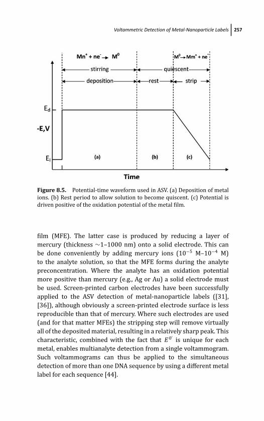
March 19, 2012 17:1 PSP Book - 9in x 6in 08-Ozsoz-c08
Voltammetric Detection of Metal-Nanoparticle Labels 257
Figure 8.5. Potential-time waveform used in ASV. (a) Deposition of metal
ions. (b) Rest period to allow solution to become quiscent. (c) Potential is
driven positive of the oxidation potential of the metal film.
film (MFE). The latter case is produced by reducing a layer of
mercury (thickness ∼1–1000 nm) onto a solid electrode. This can
be done conveniently by adding mercury ions (10−5 M–10−4 M)
to the analyte solution, so that the MFE forms during the analyte
preconcentration. Where the analyte has an oxidation potential
more positive than mercury (e.g., Ag or Au) a solid electrode must
be used. Screen-printed carbon electrodes have been successfully
applied to the ASV detection of metal-nanoparticle labels ([31],
[36]), although obviously a screen-printed electrode surface is less
reproducible than that of mercury. Where such electrodes are used
(and for that matter MFEs) the stripping step will remove virtually
all of the deposited material, resulting in a relatively sharp peak. This
characteristic, combined with the fact that E 0′is unique for each
metal, enables multianalyte detection from a single voltammogram.
Such voltammograms can thus be applied to the simultaneous
detection of more than one DNA sequence by using a different metal
label for each sequence [44].
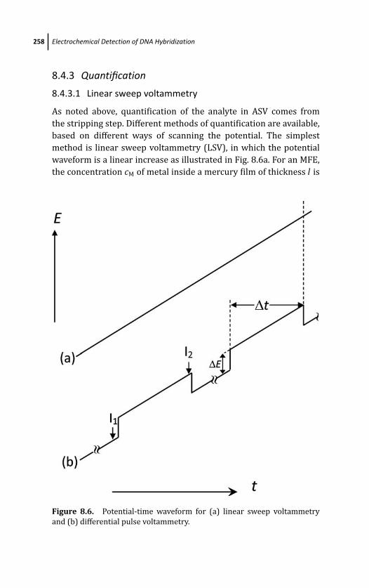
March 19, 2012 17:1 PSP Book - 9in x 6in 08-Ozsoz-c08
258 Electrochemical Detection of DNA Hybridization
8.4.3 Quantification
8.4.3.1 Linear sweep voltammetry
As noted above, quantification of the analyte in ASV comes from
the stripping step. Different methods of quantification are available,
based on different ways of scanning the potential. The simplest
method is linear sweep voltammetry (LSV), in which the potential
waveform is a linear increase as illustrated in Fig. 8.6a. For an MFE,
the concentration cM of metal inside a mercury film of thickness l is
Figure 8.6. Potential-time waveform for (a) linear sweep voltammetry
and (b) differential pulse voltammetry.
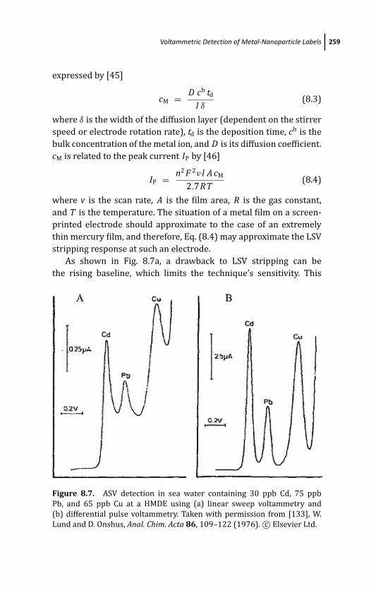
March 19, 2012 17:1 PSP Book - 9in x 6in 08-Ozsoz-c08
Voltammetric Detection of Metal-Nanoparticle Labels 259
expressed by [45]
cM = D cb td
l δ(8.3)
where δ is the width of the diffusion layer (dependent on the stirrer
speed or electrode rotation rate), td is the deposition time, cb is the
bulk concentration of the metal ion, and D is its diffusion coefficient.
cM is related to the peak current IP by [46]
IP = n2 F 2ν l A cM
2.7RT(8.4)
where v is the scan rate, A is the film area, R is the gas constant,
and T is the temperature. The situation of a metal film on a screen-
printed electrode should approximate to the case of an extremely
thin mercury film, and therefore, Eq. (8.4) may approximate the LSV
stripping response at such an electrode.
As shown in Fig. 8.7a, a drawback to LSV stripping can be
the rising baseline, which limits the technique’s sensitivity. This
Figure 8.7. ASV detection in sea water containing 30 ppb Cd, 75 ppb
Pb, and 65 ppb Cu at a HMDE using (a) linear sweep voltammetry and
(b) differential pulse voltammetry. Taken with permission from [133], W.
Lund and D. Onshus, Anal. Chim. Acta 86, 109–122 (1976). c© Elsevier Ltd.
March 19, 2012 17:1 PSP Book - 9in x 6in 08-Ozsoz-c08
260 Electrochemical Detection of DNA Hybridization
baseline represents the capacitive (i.e., non-Faradaic) current Ic
during the potential sweep. The capacitive current arises because
of the rearrangement of ions at the double layer in response to the
changing electrode potential. It is related to the scan rate by [46]
Ic = v C d [1 − exp (−t/RSC d)] (8.5)
where t is the time and RS is the solution resistance, taken as being
in series to the double-layer capacitance C d. Ic increases to reach a
constant value during the scan. Increasing the scan rate will increase
Ip, but will increase Ic by the same amount. In contrast to the
potential sweep, when a potential step to a value E is applied to
the same series resistor–capacitor combination, Ic can be shown to
decay exponentially with time according to [46]
Ic = ERS
exp (−t/RSC d) (8.6)
based on the equation for the charging of a capacitor. However, the
Faradaic current from the same potential step, as expressed by the
Cottrell equation [46], decays in proportion to 1/√
t. Therefore, the
capacitive current falls more quickly. This fact may be utilized in
pulse voltammetry to lower the baseline of the voltammogram, and
thus improve the sensitivity.
8.4.3.2 Differential pulse voltammetry
The potential waveform for differential pulse voltammetry (DPV) is
shown in Fig. 8.6b. The pulse height (�E in Fig. 8.6b) is typically
a few tens of mV, and the pulse width (�t in Fig. 8.6b) is typically
50 to 60 ms. The current is sampled immediately before the pulse is
applied (I1) and then at the end of the pulse (I2). The voltammogram
output is the difference I2–I1 plotted as a function of potential,
as shown in Fig. 8.7b. To understand the principle of DPV we can
consider the value of (I2–I1) at three different stages:
(1) Before the redox process begins. Here (I2–I1) represents the
difference in the capacitive currents at each set of the potentials
where I1 and I2 are measured. Because recording occurs after the
pauses shown in Fig. 8.6b, the currents will have decayed with time
according to Eq. (8.6). Therefore, the value of (I2–I1) will be very
small.

March 19, 2012 17:1 PSP Book - 9in x 6in 08-Ozsoz-c08
Voltammetric Detection of Metal-Nanoparticle Labels 261
(2) Once the redox process begins. The value of (I2–I1) will
now represent almost wholly the Faradaic current from the
stripping reaction. Both currents will increase first linearly and then
exponentially with potential, according to the low and high field
approximations to the Butler-Volmer equation [47]. Once the region
of exponential increase has been reached the overall value of (I2–
I1) will increase, since the potential ramp is linear and therefore I2
becomes increasingly greater than I1.
(3) After the redox peak is reached. In any potential scan of an
immobilized redox material, a peak is observed due to the depletion
of that material as the voltage is increased. In the case of DPV, once
the current sampling for I2 reaches the peak potential, I2 reaches
its maximum value. However, since the sampling of I1 lags behind,
I1 continues to rise. Therefore the value of (I2–I1) goes down.
Eventually I1 will reach the peak potential also and then (I2–I1)
will be virtually zero (the difference between them will be the small
difference in the residual capacitive current). In this manner, DPV
provides a lower baseline than LSV, as shown in Fig. 8.7b. The DPV
detection limit for a species in bulk solution is estimated at 5 × 10⁻⁸
M (c.f. 5 × 10⁻⁶ M by LSV), and for stripping this lowers to 1 × 10⁻¹¹
M due to the advantage of preconcentration (c.f. × 10−10 M for LSV)
[48]. For a species diffusing from bulk solution the DPV peak height
(I2–I1)max is given by [46]
(I2− I1)max = n F A√
D c√π
√�t
(1 − σ
1 + σ
)(8.7)
where
σ = exp
(n F �E2 R T
)(8.8)
The DPV response has also been derived for an HMDE where metal
ions are reduced at the mercury [48], but has not, to the best of
our knowledge been derived for mercury electrodes in conjunction
with ASV. This is probably because such systems are only used for
analytical calibrations and not for the determination of physical
parameters.
March 19, 2012 17:1 PSP Book - 9in x 6in 08-Ozsoz-c08
262 Electrochemical Detection of DNA Hybridization
8.4.3.3 Potentiometric stripping analysis
In addition to LSV and DPV, chronopotentiometry has also been used
to detect metal nanoparticle labels ([31], [36]). In PSA, the metal
ions from the labels are reduced onto the electrode as described
previously and then the electrode is programmed to pass a constant
current, often in the order of microamps. To satisfy this current the
electrode potential moves to a value where M0 will be reoxidized.
Once M0 is depleted from the electrode the potential must shift
positively until a new redox reaction (possibly solvent electrolysis)
can provide the current. The time τ for this potential transition is the
analytical signal corresponding to current height in voltammetry. To
the best of our knowledge the expression of τ for an MFE used in
ASV has not been derived. For ASV using a HMDE of radius r passing
a current I , τ is related to cM by [49]
τ = nF ArcM
3I− r2
15 D(8.9)
assuming that all (or a considerable part) of M0 in the mercury drop
is oxidized and that the inequality r2 < 7Dt is fulfilled. When the
drop radius is small and the current is low, the second term becomes
negligible. Some of the chronopotentiometric stripping responses
for metal nanoparticle detection [31, 36] have been reported in the
form of peaks with heights measured in units of s V−1, which means
presumably some differential of the current was measured.
8.5 Latex as a Label Support
8.5.1 Introduction
The term “latex” originally referred to the milky sap of rubber
trees and certain plants. This sap was found to be an aqueous
medium containing colloids of natural rubber, stabilized by proteins.
Laboratory-synthesized polymer colloids were hence described as
“synthetic latexes,” and finally just “latexes.” That term will be used
here. Billions of pounds of latexes are synthesized worldwide each
year, for a large variety of applications. The reasons for interest in
their use in constructing electrochemical labels are
March 19, 2012 17:1 PSP Book - 9in x 6in 08-Ozsoz-c08
Latex as a Label Support 263
• The synthetic and physical chemistry of latexes has been
well-researched, including methods to control charge, size,
and hydrophobicity [50–52].
• It is possible to synthesize latexes with a very narrow
particle size distribution.
• A latex solution provides a large solid–liquid interfacial area
for modification.
• Many methods of chemical modification of latex are
available, and high surface concentrations of functional
groups can be achieved.
8.5.2 Latex Synthesis
Latexes can be synthesized by emulsion polymerization. Originally
this meant emulsifying an aqueous-insoluble monomer in water
with a surfactant and then using a water-soluble free radical initiator
to cause polymerization. The term emulsion polymerization is still
used, despite the fact that an emulsion is not always needed to
produce polymer colloids.
There are a huge number of methods available for latex
synthesis based on many industrial applications [53] and a thorough
review of that literature is beyond the scope of this chapter.
However, in general, the reaction mixture will contain one or more
monomers bearing double bonds capable of undergoing free radical
polymerization, water, emulsifier, (i.e., a surfactant), and an initiator
compound which will decompose to form free radicals. In batch
mode, all of the reactants are added together and heated to reaction
temperature. Hence, synthesis typically requires a heating bath
and a reaction flask with openings for a stirrer, reflux condenser
and an inlet and outlet for nitrogen (because oxygen is a free
radical inhibitor). A sampling device may also be useful to monitor
the reaction by extracting aliquots of the reactant over time. The
principle of the reaction is that the initiator compound decomposes
to form free radicals
I → 2R•
which then attack the monomer molecules to initiate chain growth
R + M → M•
March 19, 2012 17:1 PSP Book - 9in x 6in 08-Ozsoz-c08
264 Electrochemical Detection of DNA Hybridization
Once a chain is started it propagates according to
Mj + M → Mj+1
As the length of the chain increases the molecule becomes
decreasingly water soluble, until it eventually comes out of the
solution and forms a primary particle. Thermal motion in the
solution causes collision between primary particles, leading to
coagulation and fusion into larger particles. These are spherical
because interfacial tension acts to minimize the interfacial area.
Since the initiator free radical is typically a water-soluble ionic group
such as SO3− or OSO3
−, it imparts a charge to the primary particle.
As primary particles coagulate, the surface charge density of the
growing sphere increases. This leads to electrostatic repulsion,
slowing and eventually stopping further coagulation. It is often easy
to produce latexes of a very narrow size distribution, described as
“monodisperse.” Synthetic methods appropriate to the construction
of micron and sub-micron sized latex electrochemical labels include
the synthesis of polystyrene (PS) latex colloids [54], which are then
present during the synthesis of polystyrenesulphonate (PSS) [55],
leading to a negative PSS shell around the PS core; the copoly-
merization of styrene and acrylic acid to produce a polystyrene-co-
acrylic acid (PSA) coploymer [56], which has a negative charge due
to acrylic acid deprotonation. Other than sulphonate and sulphates,
functional groups which can be introduced to the latex by the
initiator include alcohols, carboxylic acids, and =NH2+ [57].
8.5.3 Latex Solution Properties
In solution the latex spheres will experience van der Waals forces
of attraction, which at a separation r will be proportional to r−6.
For coagulation to not occur, these forces must be balanced by the
repulsive electrostatic force arising from either the ionic functional
groups on the latex, or adsorbed ionic surfactant. Hence, a latex
particle in an electrolyte will support a tightly bound layer of one ion
balanced by a diffuse layer of an oppositely charged ion. This diffuse
layer is equivalent to the diffuse layer at an electrode-solution
interface and so can be described by Gouy-Chapman theory [46].
Therefore, the width of the diffuse layer will be equal to the Debye

March 19, 2012 17:1 PSP Book - 9in x 6in 08-Ozsoz-c08
Latex as a Label Support 265
length κ−1, where [46]
κ =√
2n0z2e2
εε0kT(8.10)
in which n0 and z are the concentration and charge of ions in the
electrolyte, e is the charge on an electron, ε is the permittivity of the
medium, ε0 is the permittivity of free space, and k is Boltzmann’s
constant. The overall interaction between the latex particles is then
the sum of their attractive and repulsive forces, and is described
quantitatively by DVLO theory [58, 59]. The important experimental
parameter here is the electrolyte concentration, since this does not
effect van der Waals forces but when increased causes the diffuse
layer to shrink (e.g., from ∼300 A to 3 A going from 1 × 10⁻⁴ M to
1 M for a 1:1 electrolyte at 25◦C [46]). Thus, increasing electrolyte
concentration can cause coagulation. (This should also be noted
for solution phase nanoparticles since the physical principles are
exactly the same.)
8.5.4 Layer-by-Layer Deposition: Theory
In 1966, Iler demonstrated that films of alternating positively
charged alumina fibrils and negatively charged silica colloids could
be built up on hydrophilic glass [60]. In the early 1990s, Decher and
coworkers extended this procedure to the deposition from solution
of oppositely charged polyelectrolytes [61–63]. The technique,
known as “layer-by-layer” (l-b-l) deposition has since become widely
applied. The method is relatively simple, and as shown in Fig. 8.8,
consists of (1) derivatizing a substrate with a stable surface charge
excess, (2) immersing the substrate in a solution of an oppositely
charged polyelectrolyte (PE), (3) immersing in water to remove
weakly bound PE, and (4) immersing in a solution of a second PE,
oppositely charged to the first. Steps (2) to (4) can be repeated as
many times as necessary to give the required thickness. The reasons
for the popularity of the method are that, in addition to simplicity,
it allows us to control the resulting film thickness down to the level
of a few Angstroms, films of more than 1000 PE layers are possible,
the films are physically stable and are permeable to solution species,
enabling a film-confined catalyst to react with substrate. The l-b-l
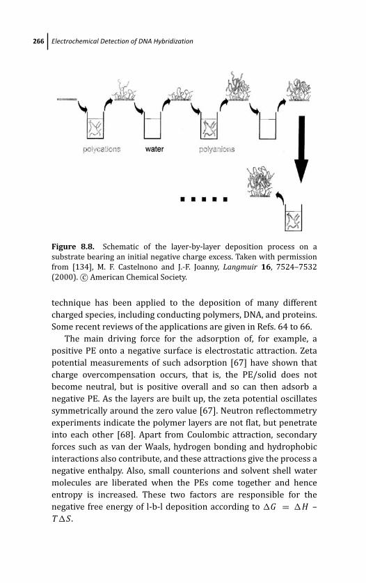
March 19, 2012 17:1 PSP Book - 9in x 6in 08-Ozsoz-c08
266 Electrochemical Detection of DNA Hybridization
Figure 8.8. Schematic of the layer-by-layer deposition process on a
substrate bearing an initial negative charge excess. Taken with permission
from [134], M. F. Castelnono and J.-F. Joanny, Langmuir 16, 7524–7532
(2000). c© American Chemical Society.
technique has been applied to the deposition of many different
charged species, including conducting polymers, DNA, and proteins.
Some recent reviews of the applications are given in Refs. 64 to 66.
The main driving force for the adsorption of, for example, a
positive PE onto a negative surface is electrostatic attraction. Zeta
potential measurements of such adsorption [67] have shown that
charge overcompensation occurs, that is, the PE/solid does not
become neutral, but is positive overall and so can then adsorb a
negative PE. As the layers are built up, the zeta potential oscillates
symmetrically around the zero value [67]. Neutron reflectommetry
experiments indicate the polymer layers are not flat, but penetrate
into each other [68]. Apart from Coulombic attraction, secondary
forces such as van der Waals, hydrogen bonding and hydrophobic
interactions also contribute, and these attractions give the process a
negative enthalpy. Also, small counterions and solvent shell water
molecules are liberated when the PEs come together and hence
entropy is increased. These two factors are responsible for the
negative free energy of l-b-l deposition according to �G = �H –
T�S .
March 19, 2012 17:1 PSP Book - 9in x 6in 08-Ozsoz-c08
Latex as a Label Support 267
Oppositely charged PEs can also form complexes in solution
[known as “interpolyelectrolyte complexes” (IPEC)] [69, 70]. Solid-
state nuclear magnetic resonance spectroscopy has shown that
these are structurally similar to l-b-l films, and hence l-b-l films
can be thought of as stacked layers of IPECs. Interestingly, IPEC
formation is almost entirely driven by the entropy increase [71],
which suggests that forces other than electrostatic attraction may
be used to form l-b-l films. This has been demonstrated for
hydrogen bonding [72–73], hydrophobic interactions [74], and DNA
hybridization [75, 76].
Where electrostatic attraction is used for l-b-l film formation,
increasing the ionic strength of the solution will generally increase
the film thickness [77, 78]. This is thought to be because a higher salt
concentration increases the shielding around the ionic groups of the
polyelectrolyte, causing it to adopt a more coiled, compact form [71,
79, 80].
8.5.5 Layer-by-Layer Modification of Latex
8.5.5.1 Latex surface charge excess
To modify latex spheres by the l-b-l method, there must be a
stable charge excess on the colloid surface (also required to prevent
coagulation). In the case of PS latex commercial samples are
available, from suppliers such as Sigma, bearing sulphate groups.
Otherwise, those groups can be imparted by synthesizing PSS in the
presence of PS [55]. PSS is a strong electrolyte and therefore can be
expected to be fully dissociated. In the case of PSA latex copolymers
[56] the negative charge will be dependent on the polyacrylic acid
(PAH) deprotonation and therefore on the contacting pH. This
deprotonation was studied in detail recently for sub-micron PSA
spheres by Li et al. [81]. The dissociation proceeded as
(latex) − COOH + OH− → (latex) − COO− + H2O
Based on UV absorbances measured after latex dissolution, it was
found that the PAH:PS ratio in the solid was 0.34, resulting in
latexes that were highly hydrophobic. This meant that deprotonation
only extended approx. 1.5 nm into the sphere, which for the
diameter of 0.265 μm means that of the total PAH in the particle
March 19, 2012 17:1 PSP Book - 9in x 6in 08-Ozsoz-c08
268 Electrochemical Detection of DNA Hybridization
only approximately 3% was dissociated. The rate constant for
PAH dissociation on the latex decreased with increasing pH, as
expected, and was one order of magnitude lower than the value for
dissociation of PAH in solution at the same pH. This was attributed
to the hindering effect of neighboring −COO− groups on the latex
surface.
(a) Electrochemical labels by adsorption
Thus far, most of the studies of l-b-l material loading onto latex
spheres has focused on the layered deposition of biological macro-
molecules such as hemoglobin [82], DNA [75, 76], immunoglobulin
G [83], or enzymes such as glucose oxidase [84], horseradish
peroxidase [84], urease [85], and tyrosinase [55]. The layers were
deposited typically on PS latex stabilized by negative surface groups.
The available charge of the biological molecules, at any pH other
than the isoelectric point, meant that the deposited species could
replace one of the polyelectrolytes. To modify latex colloids the l-
b-l process is performed by adding the polyelectrolyte or biological
molecule to a colloidal suspension of the charge excess latex. After
20 min to 1 h (often under stirring), the suspension is centrifuged
down to a pellet and the solution decanted off to be replaced by
water. The colloids are then redispersed into the water by vortex
shaking. The centrifugation/water redispersion is performed twice
more. This provides the rinsing step noted previously to remove
weakly bound material. An oppositely charged material can then be
incubated with the latex in the same manner. Overall, the process is
simple and almost as reproducible as the modification of a planar
surface (allowing for a possible size distribution of the latex). Where
zeta potentials have been measured [83–85], the oscillating values
characteristic of l-b-l deposition have been found.
To the best of our knowledge, the previous l-b-l nanoparticle
modifications of latex have all been directed at incorporation into
the walls of hollow capsules, as described below. However, if metal
nanoparticles are stabilized by a surface charge then they can
be adsorbed to appropriately modified l-b-l latex by electrostatic
attraction, as shown in Fig. 8.1b. In this figure, the gold nanoparticles
were produced by citrate reduction and so had a negative charge
March 19, 2012 17:1 PSP Book - 9in x 6in 08-Ozsoz-c08
Latex as a Label Support 269
due to the adsorbed citrate. The particles were attached in a
manner analogous to polyelectrolytes: a dispersion of nanoparticles
was added to the latex suspension and then incubated at room
temperature for 30 min. The modified latex was then isolated by
filtration with a membrane (pore size 0.2 μm) which would admit
the unattached gold particles (mean diameter = 15.5 nm ± 1.6 nm),
but not the latex (mean diameter = 0.338 μm and 0.493 μm). We
found that the 0.493-μm latex had a higher gold coverage. Latex
particles have also been modified by coating with streptavidin and
then attached to biotin-coated gold nanoparticles via the strong
avidin-biotin bond [86]. However, the method gave a nanoparticle
coverage of 1 order of magnitude less than l-b-l deposition. This
corresponded to 2 orders of magnitude less metal ions released, due
to using gold nanoparticles of a smaller size.
(b) Electrochemical labels from hollow capsules
Capsule Formation: The l-b-l based construction of hollow capsules
was developed mainly as a technique for achieving localized drug
delivery, since the capsule can protect the drug from degradation
by the body. Recent thorough reviews of capsule formation and use
are available [87–91]. As shown in Fig. 8.9, there are three general
methods of constructing the capsules: (A) loading a preformed
capsule, (B) encapsulating crystals by l-b-l assembly, and (C)
incorporation into a porous sphere which is then coated by an l-b-l
process. The construction of nanoparticle electrochemical labels
from latex is based on method (A) and so only that will be
discussed further. The preformed capsule used in (A) is made by
l-b-l deposition onto an organic core which is then dissolved, as
shown in Fig. 8.10. Typical latexes which have been used for the
core are PSS and PSA, both of which have a negative surface charge,
as explained earlier, that can be utilized for l-b-l modification. Both
cores can be dissolved by THF. Other organic cores which have
been used for this method are melamine formaldehyde (MF), which
dissolves at low pH, and polylactic acid (PLA) or polylactic-co-
glycolic acid (PLGA), which can be dissolved in acetone/N -methyl-
2-pyrrolidinone mixtures. It should be noted that in this type
of capsule formation, the incomplete removal of core material is
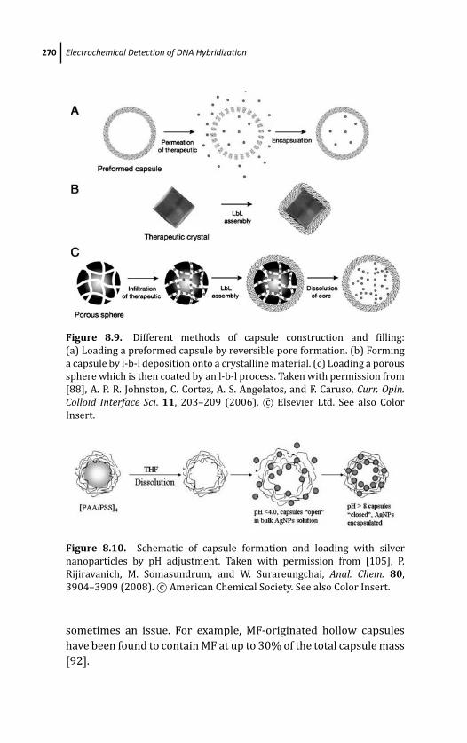
March 19, 2012 17:1 PSP Book - 9in x 6in 08-Ozsoz-c08
270 Electrochemical Detection of DNA Hybridization
Figure 8.9. Different methods of capsule construction and filling:
(a) Loading a preformed capsule by reversible pore formation. (b) Forming
a capsule by l-b-l deposition onto a crystalline material. (c) Loading a porous
sphere which is then coated by an l-b-l process. Taken with permission from
[88], A. P. R. Johnston, C. Cortez, A. S. Angelatos, and F. Caruso, Curr. Opin.Colloid Interface Sci. 11, 203–209 (2006). c© Elsevier Ltd. See also Color
Insert.
Figure 8.10. Schematic of capsule formation and loading with silver
nanoparticles by pH adjustment. Taken with permission from [105], P.
Rijiravanich, M. Somasundrum, and W. Surareungchai, Anal. Chem. 80,
3904–3909 (2008). c© American Chemical Society. See also Color Insert.
sometimes an issue. For example, MF-originated hollow capsules
have been found to contain MF at up to 30% of the total capsule mass
[92].
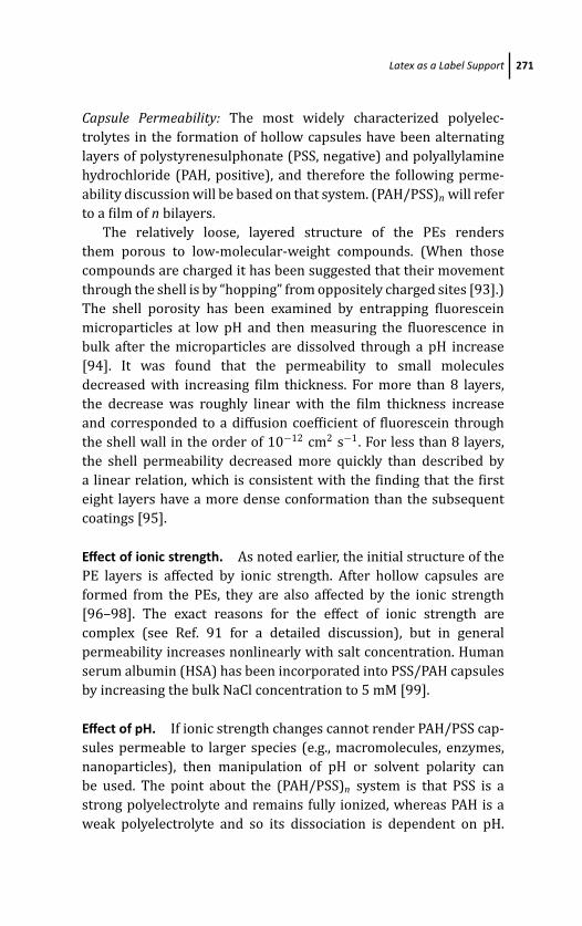
March 19, 2012 17:1 PSP Book - 9in x 6in 08-Ozsoz-c08
Latex as a Label Support 271
Capsule Permeability: The most widely characterized polyelec-
trolytes in the formation of hollow capsules have been alternating
layers of polystyrenesulphonate (PSS, negative) and polyallylamine
hydrochloride (PAH, positive), and therefore the following perme-
ability discussion will be based on that system. (PAH/PSS)n will refer
to a film of n bilayers.
The relatively loose, layered structure of the PEs renders
them porous to low-molecular-weight compounds. (When those
compounds are charged it has been suggested that their movement
through the shell is by “hopping” from oppositely charged sites [93].)
The shell porosity has been examined by entrapping fluorescein
microparticles at low pH and then measuring the fluorescence in
bulk after the microparticles are dissolved through a pH increase
[94]. It was found that the permeability to small molecules
decreased with increasing film thickness. For more than 8 layers,
the decrease was roughly linear with the film thickness increase
and corresponded to a diffusion coefficient of fluorescein through
the shell wall in the order of 10−12 cm2 s−1. For less than 8 layers,
the shell permeability decreased more quickly than described by
a linear relation, which is consistent with the finding that the first
eight layers have a more dense conformation than the subsequent
coatings [95].
Effect of ionic strength. As noted earlier, the initial structure of the
PE layers is affected by ionic strength. After hollow capsules are
formed from the PEs, they are also affected by the ionic strength
[96–98]. The exact reasons for the effect of ionic strength are
complex (see Ref. 91 for a detailed discussion), but in general
permeability increases nonlinearly with salt concentration. Human
serum albumin (HSA) has been incorporated into PSS/PAH capsules
by increasing the bulk NaCl concentration to 5 mM [99].
Effect of pH. If ionic strength changes cannot render PAH/PSS cap-
sules permeable to larger species (e.g., macromolecules, enzymes,
nanoparticles), then manipulation of pH or solvent polarity can
be used. The point about the (PAH/PSS)n system is that PSS is a
strong polyelectrolyte and remains fully ionized, whereas PAH is a
weak polyelectrolyte and so its dissociation is dependent on pH.
March 19, 2012 17:1 PSP Book - 9in x 6in 08-Ozsoz-c08
272 Electrochemical Detection of DNA Hybridization
Therefore, the effect of pH on the capsule can be understood by
considering the effect of pH on the PAH layers. Those layers are
protonated according to the equilibrium
R − NH2 + H3O+ � R − NH3+ + OH−
The protonation has two effects: (1) Mutual repulsion from
neighboring −NH3+ sites causes a “stretching out” of the molecule.
Simulations on commercial software suggest the PAH length
increases by 7% from uncharged (pH 10.0) to fully charged (pH 3.0)
[91]. (2) The formation of −NH3+ requires charge compensation
by counterions. Each counterion is surrounded by a shell of H2O
molecules and their entry into the film causes osmotic pressure
between the PEs. These two factors combine to result in an opening
up of the film structure. The opening has been observed by scanning
force microscopy [93]. Capsules exposed to acidic solution exhibited
pores of up to 100 nm diameter, while capsules at pH 10.0 showed
no such effect. The same thing has also been observed for the
PAH/PSS system deposited on a planar surface [100]. Importantly,
when capsules from an acidic solution were transferred to a solution
at pH 10.0 the pores could not be observed [93]. Hence, the capsule
opening is reversible, and so pH may be manipulated to entrap large
molecules within the capsules. Such entrapment has been studied
by confocal microscopy using fluorescent-labeled dextran, and it
was demonstrated that in acidic conditions dextrans entered the
capsules [91]. Polyions and proteins have also been entrapped by
this method [101].
Effect of solvent polarity. Solvent polarity affects capsule perme-
ability by changing the solubility of the capsule walls. In the case
of PAH/PSS pairs, they are insoluble in water and soluble in ethanol.
Hence, varying the water-to-ethanol ratio of the suspension medium
can lead to a loosening of the film structure. At 20% ethanol content
a significant increase in the shell permeability was noted for a range
of high-molecular-weight materials including dextrans and proteins
[102]. As with pH-induced changes, the opening was found to be
reversible and could therefore be used for encapsulation.
Maximum loading. If the loading of the PE capsules is driven
solely by the concentration gradient across the capsule walls,
March 19, 2012 17:1 PSP Book - 9in x 6in 08-Ozsoz-c08
Latex as a Label Support 273
then we can expect the concentration of the loaded compound to
eventually become equal to its concentration in bulk solution. This
was found to be true for fluorescent-labeled HSA as quantified by
confocal microscopy [99]. However, in some cases enzymes have
been encapsulated at an internal concentration of over three orders
of magnitude greater than the bulk value [103, 104], and we have
incorporated silver nanoparticles at an effective concentration four
orders of magnitude greater than the bulk value [105]. This suggests
an additional driving force for encapsulation, possibly adsorption to
either the inner capsule walls or to undissolved core material.
Incorporation of nanoparticles: Metal nanoparticles were first
incorporated into the shells of hollow capsules [106] in order
to trigger light-assisted opening of the capsules [107–109]. This
technique was directed at the localized delivery of drugs at a
high dosage, the concept being that illumination in the near-IR
wavelength would cause heating of the nanoparticles and thus
degrade the shell walls. So far, hollow shells have been modified
by silver [108, 110, 111], gold [107, 109, 112, 113], and palladium
[110]. The modification has been performed by (a) depositing
(PAH/PSS)2 onto a latex core, reducing Ag+ onto the layers, then
depositing a further (PAH/PSS)2, followed by core dissolution [106,
108], or (b) forming (PAH/PSS)n shells by core dissolution and then
incubating with metal nanoparticles to allow adsorption, followed
by deposition of a further PSS layer [109].
We have found that Ag nanoparticles can be entrapped con-
veniently in (PAH/PSS)4 shells by pH manipulation, as shown in
Fig. 8.11 [105]. Because previous research was directed at light-
assisted capsule opening, there has not, to the best of our knowledge,
been any attempt to quantify the nanoparticle loading of the
capsules. However, as described below, this can be achieved to an
order of magnitude accuracy via voltammetry, UV absorbance, and
TEM. Using this process we estimated our loading as approximately
78 silver nanoparticles per capsule. From the mean size of the
nanoparticles (diameter = 15.8 nm), this corresponds to the release
of 9 × 10⁶ Ag+ ions after acid dissolution. To determine the
distribution of the nanoparticles, we applied the same method
of quantification to nanoparticles adsorbed onto glass cover slips
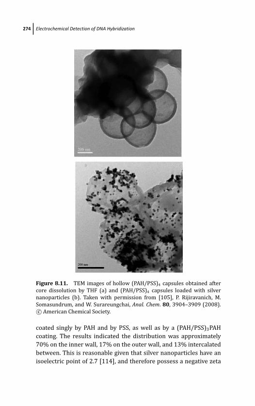
March 19, 2012 17:1 PSP Book - 9in x 6in 08-Ozsoz-c08
274 Electrochemical Detection of DNA Hybridization
Figure 8.11. TEM images of hollow (PAH/PSS)4 capsules obtained after
core dissolution by THF (a) and (PAH/PSS)4 capsules loaded with silver
nanoparticles (b). Taken with permission from [105], P. Rijiravanich, M.
Somasundrum, and W. Surareungchai, Anal. Chem. 80, 3904–3909 (2008).
c© American Chemical Society.
coated singly by PAH and by PSS, as well as by a (PAH/PSS)3PAH
coating. The results indicated the distribution was approximately
70% on the inner wall, 17% on the outer wall, and 13% intercalated
between. This is reasonable given that silver nanoparticles have an
isoelectric point of 2.7 [114], and therefore possess a negative zeta
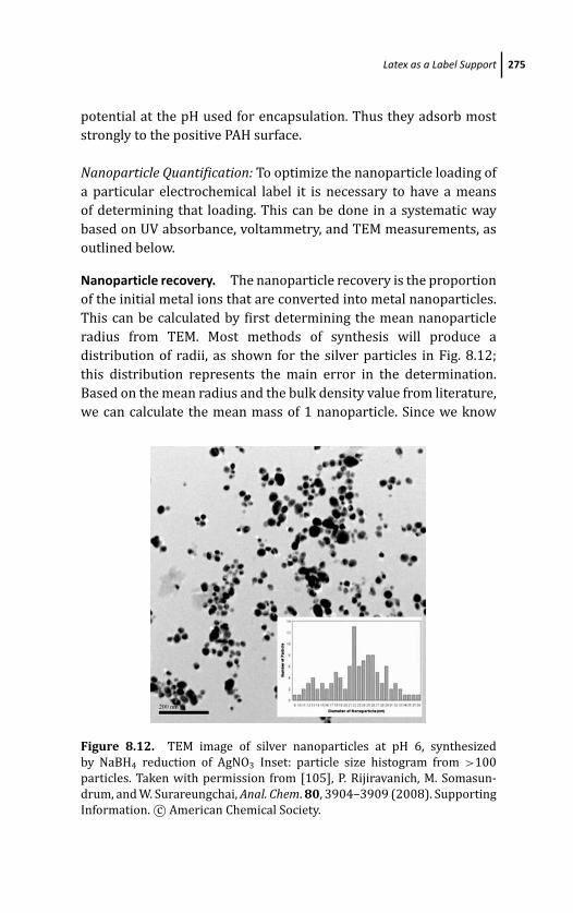
March 19, 2012 17:1 PSP Book - 9in x 6in 08-Ozsoz-c08
Latex as a Label Support 275
potential at the pH used for encapsulation. Thus they adsorb most
strongly to the positive PAH surface.
Nanoparticle Quantification: To optimize the nanoparticle loading of
a particular electrochemical label it is necessary to have a means
of determining that loading. This can be done in a systematic way
based on UV absorbance, voltammetry, and TEM measurements, as
outlined below.
Nanoparticle recovery. The nanoparticle recovery is the proportion
of the initial metal ions that are converted into metal nanoparticles.
This can be calculated by first determining the mean nanoparticle
radius from TEM. Most methods of synthesis will produce a
distribution of radii, as shown for the silver particles in Fig. 8.12;
this distribution represents the main error in the determination.
Based on the mean radius and the bulk density value from literature,
we can calculate the mean mass of 1 nanoparticle. Since we know
Figure 8.12. TEM image of silver nanoparticles at pH 6, synthesized
by NaBH4 reduction of AgNO3 Inset: particle size histogram from >100
particles. Taken with permission from [105], P. Rijiravanich, M. Somasun-
drum, and W. Surareungchai, Anal. Chem. 80, 3904–3909 (2008). Supporting
Information. c© American Chemical Society.

March 19, 2012 17:1 PSP Book - 9in x 6in 08-Ozsoz-c08
276 Electrochemical Detection of DNA Hybridization
the metal ion concentration used in the synthesis, we can calculate
the total mass of the nanoparticles assuming a 100% conversion,
[M ]100%. The actual mass of nanoparticles, [M ]exp, can then be
determined by acid-dissolution of a known aliquot followed by ASV
analysis, having plotted a calibration curve for that metal ion. The
recovery is obviously [M ]exp/ [M ]100%.
Nanoparticle stock concentration The total number of nanoparti-
cles is given by
mass of metal ion used in synthesis
x mass of 1 particle× recovery = no. of particles
From the volume used in the synthesis this can be converted to a
concentration of nanoparticles mL−1.
Capsule/latex concentration. A TEM image of some (PAH/PSS)4
capsules is shown in Fig. 8.10a, and a sub-micron PSA latex particle
shown in Fig. 8.13. The mass of one capsule or particle can be
calculated from the shell or particle dimensions, assuming a density
of 1.01 g cm−3 for the capsule and 1.05 g cm−3 for the particle [55].
Figure 8.13. TEM image of 493 nm diameter PSA particle. Taken with
permission from [131], S. Pinijsuwan, P. Rijiravanich, M. Somasundrum,
and W. Surareungchai, Anal. Chem. 80, 6779–6784 (2008). Supporting
Information. c© American Chemical Society.

March 19, 2012 17:1 PSP Book - 9in x 6in 08-Ozsoz-c08
Latex as a Label Support 277
By determining the dry weight of a known aliquot deposited onto a
glass slide, we can then calculate the concentration per mL.
Nanoparticle loading. The nanoparticle suspension should have a
UV/vis absorbance maxima. Since the nanoparticle stock concen-
tration is now known, this maxima can be used for calibration
as shown in Fig. 8.14 for 15.8-nm diameter silver nanoparticles
Figure 8.14. (a) Absorbance spectra of silver nanoparticles shown in
Fig. 8.12 (b) Calibration of silver nanoparticles from absorbance at 406 nm
following determination of stock concentration. Taken with permission
from [105], P. Rijiravanich, M. Somasundrum, and W. Surareungchai,
Anal. Chem. 80, 3904–3909 (2008). Supporting Information. c© American
Chemical Society.
March 19, 2012 17:1 PSP Book - 9in x 6in 08-Ozsoz-c08
278 Electrochemical Detection of DNA Hybridization
(λmax = 406 nm). Hence, after take-up of silver particles by
the capsules/latex particles, the nanoparticles remaining in the
solution can be separated after centrifugation and the remaining
concentration determined. Knowledge of the initial concentration
used enables us to calculate the number of nanoparticles taken up.
Knowledge of the number of capsules/latex particles allows us to
calculate the capsule/latex loading.
8.6 DNA Measurement
The nanoparticle labels can be used to detect DNA following the
general stages: (1) Attachment of DNA probe or target to the
electrode, (2) attachment of DNA probe or target to the label, (3)
hybridization to form a duplex, (4) dissolution of the metal ions in
the label (50% HNO3 for Ag dissolution, 1 M HBr/0.1 mM Br2 for
Au), and (5) detection of the metal ions.
DNA probes are usually in the range 12–40 base pairs. Above 40
base pairs, folding of the probe on the electrode is likely to lower
hybridization efficiency by steric hindrance. Also, at such lengths
the degree of binding to partial mismatches may be significant. At
below 12 base pairs the probe is unlikely to be unique to a particular
sequence.
8.6.1 DNA Immobilization
DNA can be immobilized on the electrode by either covalent linking
or physical adsorption. DNA modified by a thiol group can be
chemically attached to gold electrodes [115–117] following the
formation of the sulphur-gold bond:
DNA − SH + Au → DNA − S − Au + e− + H+
Alternatively, the gold electrode can be modified with a thiol-based
self-assembled monolayer (SAM) bearing functional groups suitable
to bind DNA [118]. Often this binding is performed via a coupling
reagent such as 1-ethyl-3-(3-dimethylaminopropyl)carbodiimide
(EDC), which enables aminated or carboxylated DNA to bond with
the appropriately carboxylated or aminated functional group on
the electrode [119], or on a polymer deposited on the electrode
March 19, 2012 17:1 PSP Book - 9in x 6in 08-Ozsoz-c08
DNA Measurement 279
[120]. Thiol-based linkage to the DNA means that at high coverages
the DNA is oriented normal to the electrode. If we approximate
the oligonucleotide molecule to a cylinder, then the maximum
possible loading is defined by the diameter of the cylinder. This
value is 20 A [121]. The coverage from such immobilization can be
calculated using the chronocoulometric method described by Steel
et al. [121]. The principle of the method is that [Ru(NH3)6]3+ is
used to compensate the negatively charged phosphate groups of
the DNA under conditions of low supporting electrolyte. Therefore,
when DNA is immobilized at the electrode surface the concentration
of [Ru(NH3)6]3+ is increased. The coverage Γ of DNA-bound
[Ru(NH3)6]3+ is determined by stepping the potential to a value
where [Ru(NH3)6]3+ is reduced at a diffusion-limited rate. From the
integrated form of the Cottrell equation [46], a plot of charge Qagainst
√t will have a y-intercept equal to Q dl + nF AΓ , where Q dl
is the double-layer charge, determined from the same potential step
in the absence of [Ru(NH3)6]3+. There are Γ NA molecules/cm2 of
[Ru(NH3)6]3+ on the electrode, where NA is Avagadro’s number, and
therefore, assuming each [Ru(NH3)6]3+ molecule is compensated
by three phosphate groups, and there are m phosphate groups
on one DNA probe, there are (3/m)Γ NA DNA probes/cm2 on the
electrode. The technique can be applied to ss and dsDNA and
thus the hybridization efficiency can be determined. Some studies
have suggested that the efficiency decreases with DNA coverage
[122]. When thiol-modified DNA is immobilized on gold, a “diluent”
alkanethiol is often also adsorbed to displace weakly bound DNA
bases. In these cases, the chronocoulometric method has indicated
that hybridization efficiency increases with DNA length above the
diluent layer [123].
A much simpler method of immobilization is direct adsorption,
in which case we would expect the DNA to be oriented horizontally
along the electrode. Therefore, the maximum coverage will be
determined by the number of layers it is possible to deposit.
Forces such as hydrogen bonding, base stacking, van der Waals and
hydrophobic interactions are expected to be involved [124]. Due to
the negative charges of the phosphate groups, the adsorption can be
assisted by electrostatic attraction. Glassy carbon electrodes have
been used to bind DNA after modification by the cationic polymer
chitosan [120]. Another way to assist electrostatic attraction is to
March 19, 2012 17:1 PSP Book - 9in x 6in 08-Ozsoz-c08
280 Electrochemical Detection of DNA Hybridization
hold the electrode at a positive potential. AFM studies of ssDNA
immobilized on a pyrolytic graphite electrode showed that holding
the electrode at 300 mV (vs. Ag wire) increased the film thickness
of the adsorbed ssDNA film from 0.98 ± 0.40 nm (open-circuit
adsorption) to 2.37 ± 0.4 nm, which suggests that at a positive
potential more than a single monolayer was adsorbed [124]. The
electrode was almost completely covered, with very few holes.
In the case of screen-printed carbon electrodes, we have used a
mildly positive potential (100 mV vs. AgCl screen-printed track
for 30s) which produced a strong adsorption, such that the DNA
remained adsorbed after washing. This method is attractive since
the electrodes are disposable and, as noted earlier, it means only a
small solution volume is needed.
8.6.2 Probe Attachment
A convenient method of attaching latex-based labels to DNA is the
avidin (or streptavidin)-biotin system, which has been widely used
[125–130]. DNA sequences with a biotin tag at the 5’ end are
commercially available. Avidin and streptavidin are proteins which
possess a high binding affinity for biotin (K a = 1015 M−1) and can
be adsorbed onto labels by incubating the labels in an appropriate
solution (e.g., in 3 mg mL−1 of protein for at least 15 min). Uptake
of the protein can be monitored by centrifuging down the solid and
then decanting off the liquid. A reduction in protein absorbance
at 280 nm confirms uptake onto the label. The main difference
between the two proteins is in the value of the isoelectric point (5
for streptavidin and 10.5 for avidin), and in the fact that streptavidin
is much more expensive. In labeling hollow capsules and latex we
used pH values that would render avidin positive. This facilitated
adsorption to the negative PSS outer layer of the capsules. In the case
of adsorption to gold-modified latex, we expect the main location of
the avidin to be on the negatively charged gold particles, since the
PAH latex outer layer is positive.
8.6.3 Detection Sequence
The simplest detection scheme is to use a single probe to detect
the target, with either the target or the probe being labeled. This

March 19, 2012 17:1 PSP Book - 9in x 6in 08-Ozsoz-c08
DNA Measurement 281
Figure 8.15. Scheme of the DNA hybridization detection procedure using
the Au nanoparticle–coated latex labels shown in Fig. 8.1 [131], taken with
permission from S. Pinijsuwan, P. Rijiravanich, M. Somasundrum, and W.
Surareungchai, Anal. Chem. 80, 6779–84 (2008). c© American Chemical
Society. See also Color Insert.
form of detection was used by us to quantify latex-based labels,
following target immobilization, as shown in Fig. 8.15. While this
system is convenient if the experimental objective is to develop the
construction of the labels, it is not an ideal method for real samples.
As shown in Fig. 8.16 target sequences of a one base mismatch can
give a significant response. Since we would expect some mismatched
sequences in the sample to be immobilized also, this would provide
interference. A technique to minimize this form of interference is to
use two probes for one target, as shown in Fig. 8.17. A capture probe
is immobilized on the electrode, and then hybridized to one section
of the target. A signal probe, carrying the label, is then bound to a
remaining section.
Using the single-probe method, a 30-base sequence common to
five strains of E. coli could be detected using the latex-based labels,
with detection limits of ∼25 fM (silver nanoparticles on hollow
capsules) [105] and ∼0.5 fM (gold nanoparticles on latex) [131], as
shown in Fig. 8.18. The lower detection limit for the second method
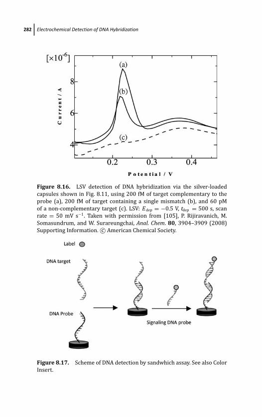
March 19, 2012 17:1 PSP Book - 9in x 6in 08-Ozsoz-c08
282 Electrochemical Detection of DNA Hybridization
Figure 8.16. LSV detection of DNA hybridization via the silver-loaded
capsules shown in Fig. 8.11, using 200 fM of target complementary to the
probe (a), 200 fM of target containing a single mismatch (b), and 60 pM
of a non-complementary target (c). LSV: Edep = −0.5 V, tdep = 500 s, scan
rate = 50 mV s−1. Taken with permission from [105], P. Rijiravanich, M.
Somasundrum, and W. Surareungchai, Anal. Chem. 80, 3904–3909 (2008)
Supporting Information. c© American Chemical Society.
Figure 8.17. Scheme of DNA detection by sandwhich assay. See also Color
Insert.
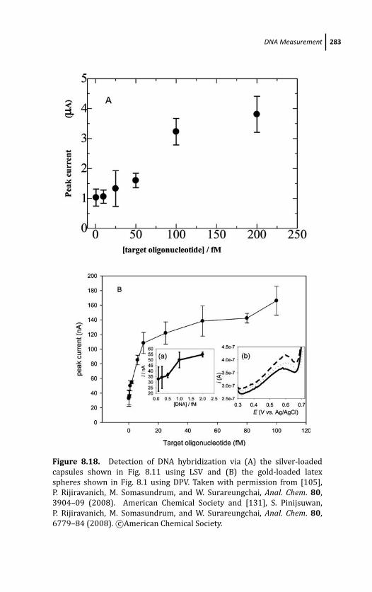
March 19, 2012 17:1 PSP Book - 9in x 6in 08-Ozsoz-c08
DNA Measurement 283
(
Figure 8.18. Detection of DNA hybridization via (A) the silver-loaded
capsules shown in Fig. 8.11 using LSV and (B) the gold-loaded latex
spheres shown in Fig. 8.1 using DPV. Taken with permission from [105],
P. Rijiravanich, M. Somasundrum, and W. Surareungchai, Anal. Chem. 80,
3904–09 (2008). American Chemical Society and [131], S. Pinijsuwan,
P. Rijiravanich, M. Somasundrum, and W. Surareungchai, Anal. Chem. 80,
6779–84 (2008). c©American Chemical Society.
March 19, 2012 17:1 PSP Book - 9in x 6in 08-Ozsoz-c08
284 Electrochemical Detection of DNA Hybridization
is from a combination of a higher nanoparticle loading and the use
of DPV for quantitation, instead of LSV.
8.7 Areas for Further Research
It is hoped that this chapter has transmitted two general points:
that it is relatively straightforward to adapt latex colloids for use
as electrochemical labels, and that very little has been done in this
field up to now. Some possible further directions for research are as
follows:
1. Increasing the nanoparticle loading on the latex spheres via the
autocatalytic metal deposition previously described [35, 36].
2. Increasing the nanoparticle loading on the hollow capsules by
finding a way to load the central volume of the capsules, rather
than just the capsule walls.
3. Applying either latex or capsule labels to multianalyte detection
by preparing labels loaded with different metals.
4. Designing a cell arrangement to reduce the electrolyte volume
needed for ASV. This would increase sensitivity by increasing the
concentration of the liberated metal ions.
5. Extending the use of latex-based labels to the analysis of real
samples.
It should also be noted that many of the previously reported latex
l-b-l modifications have described the deposition of layers of redox
enzymes [55, 84, 85], and hence these structures could also be
used as labels. Hollow capsules have also been used to entrap
enzymes [101]. While enzyme stability can sometimes be an issue,
the sensitivity provided by enzymes is often very good. For example,
l-b-l deposition of alkaline phosphatase onto carbon nanotubes
resulted in electrochemical DNA sensing down to 5.4 aM [132]. In
comparison with a nanotube, a latex sphere of diameter ∼0.5 μm
presents a very much larger surface area for immobilization. Finally,
virtually everything stated in this chapter regarding DNA labeling
can equally be applied to the labeling of antibodies.
March 19, 2012 17:1 PSP Book - 9in x 6in 08-Ozsoz-c08
References 285
Acknowledgments
The authors would like to thank Chatuporn Phantong for assistance
in preparing the figures in this chapter.
References
1. A. Sassolas, B. D. Leca-Bouvier, and L. J. Blum, Chem. Rev. 108, 109
(2008).
2. M. J. A. Shiddiky and Y.-B. Shim, Anal. Chem. 79, 3724 (2007).
3. T. G. Drummond, M. G. Hill, and J. K. Barton, Nat. Biotechnol. 21, 1192
(2003).
4. K. M. Millan and S. R. Mikkelsen, Anal. Chem. 65, 2317 (1993).
5. E. Katz and I. Willner, Angew. Chem. Int. Ed. 43, 6042 (2004).
6. E. Katz and I. Willner, J. Wang, Electroanal. 16, 19 (2004).
7. A. Merkoci, M. Aldavert, S. Marin, and S. Alegret, Tr. Anal. Chem. 24, 341
(2005).
8. M. Faraday, Phil. Trans. 147, 145 (1857).
9. J. Turkevich, J. Hillier, and P. C. Stevenson, Discuss. Faraday Soc. 11, 55
(1951).
10. A. Henglein, B. G. Ershov, and M. Malow, J. Phys. Chem. 99, 14129
(1995).
11. J. Creighton, C. Blatchford, and M. Albrecht, J. Chem. Soc. Faraday Trans.
2, 790 (1979).
12. D. A. Weitz, M. Y. Lin, and C. J. Standoff, Surf. Sci. 158, 147 (1985).
13. D. H. Napper, Polymeric Stabilization of Colloidal Dispersions, Academic
Press, New York (1983).
14. T. S. Ahmadi, Z. L. Wang, T. C. Green, A. Henglein, and M. A. El-Sayed,
Science 272, 1924 (1996).
15. M. Giersig and P. Mulvaney, Langmuir 9, 3408 (1993).
16. K. S. Mayya, V. Patil, and M. Sastry, Langmuir 13, 3944 (1997).
17. J. Eastoe, M. J. Hollamby, and L. Hudson, Adv. Colloid Interface Sci. 5,
128–130, (2006).
18. M.-P. Pileni, Nature 2, 145 (2003).
19. B. L. Cushing, V. L. Kolesnichenko, and C. J. O’Connor, Chem. Rev. 104,
3893 (2004).
March 19, 2012 17:1 PSP Book - 9in x 6in 08-Ozsoz-c08
286 Electrochemical Detection of DNA Hybridization
20. J. Eastoe and S. Gold, Phys. Chem. Chem. Phys. 7, 1352 (2005).
21. L. Li, W. Qing-Sheng, D. Ya-Ping, and W. Pei-Ming, Mater. Lett. 59, 1623
(2005).
22. M. Hussein, E. Rodil, and J. Vera, Langmuir 19, 8467 (2003).
23. P. He, X. Shen, and H. Gao, J. Colloid Interface Sci. 284, 510 (2005).
24. M. Ji, X. Chen, C. M. Wai, and J. L. Fulton, J. Am. Chem. Soc. 121, 2631
(1999).
25. C. L. Kitchens, M. C. McLeod, and C. B. Roberts, Langmuir 21, 5166
(2005).
26. C. A. Mirkin, R. L. Letsinger, R. C. Mucic, and J. J. Storhoff, Nature 382,
607 (1996).
27. R. Elghanian, J. J. Storhoff, R. C. Mucic, R. L. Letsinger, and C. A. Mirkin,
Science 277, 1078 (1997).
28. J. J. Storhoff, R. Elghanian, R. C. Mucic, C. A. Mirkin, and R. L. Letsinger,
J. Am. Chem. Soc. 120, 1959 (1998).
29. M. Dequaire, C. Degrand, and B. Limoges, Anal. Chem. 72, 5251 (2000).
30. L. Authier, C. Grossiord, P. Brossier, and B. Limoges, Anal. Chem. 73,
4450 (2001).
31. J. Wang, D. Xu, A.-N. Kawde, and R. Polsky, Anal. Chem. 73, 5576 (2001).
32. M. Ozsoz, A. Erdem, K. Kerman, D. Ozkan, B. Tugrul, N. Topcuoglu, H.
Ekren, and M. Taylan, Anal. Chem. 75, 2181 (2003).
33. H. Cai, Y. Xu, N. Zhu, P. He, and Y. Fang, Analyst 127, 803 (2002).
34. H. Cai, N. Zhu, Y. Jiang, P. He, and Y. Fang, Biosens. Bioelectron. 18, 1311
(2003).
35. T. A. Taton, C. A. Mirkin, and R. L. Letsinger, Science 289, 1757 (2000).
36. J. Wang, R. Polsky, and D. Xu, Langmuir 17, 5739 (2001).
37. J. Wang, D. Xu, and R. Polsky, J. Am. Chem. Soc. 124, 4208 (2002).
38. H. Cai, Y. Wang, P. He, and Y. Fang, Anal. Chim. Acta 469, 165 (2002).
39. T. M.-H. Lee, H. Cai, and I.-M. Hsing, Analyst 130, 364 (2005).
40. M. Rochelet-Dequaire, B. Limoges, and P. Brossier, Analyst 131, 923
(2006).
41. K.-T. Liao, J.-T. Cheng, C.-L. Li, R.-T. Liu, and H.-J. Huang, Biosens.Bioelectron. 24, 1899 (2009).
42. T. Selvaraju J. Das K. Jo, K. Kwon, C.-H. Huh, T. K. Kim, and H. Yang
Langmuir 24, 9883 (2008).
43. R. Polsky, R. Gill, L. Kaganovsky, and I. Willner, Anal. Chem. 78, 2268
(2006).
March 19, 2012 17:1 PSP Book - 9in x 6in 08-Ozsoz-c08
References 287
44. J. Wang, A. Liu, and A. Merkoci, J. Am. Chem. Soc. 125, 3214 (2003).
45. Z. Galus, Fundamentals of Electrochemical Analysis 2nd ed., Ellis
Horwood, New York (1994).
46. A. J. Bard and L. R. Faulkner, Electrochemical Methods, Fundamentalsand Applications 2nd ed., John Wiley & Sons Inc., New York (2001).
47. J. O.’M. Bockris, A. K. N. Reddy, and M. Gamboa-Aldeco, ModernElectrochemistry vol. 2, 2nd ed., Kluwer Academic/Plenum Publishers,
New York (2000).
48. H. E. Keller and R. A. Osteryoung, Anal. Chem. 43, 342 (1971).
49. Z. Galus, W. Kemula, and S. Sacha, J. Polarog. Soc. 14, 59 (1968).
50. A. Elaissari (ed.), Colloidal Polymers. Synthesis and CharacterisationMarcel Dekker, Inc., New York (2003).
51. E. S. Daniels, E. D. Sudol, and M. S. El-Asser (eds.), Polymer Colloids.Science and Technology of Latex Systems ACS Symposium Series 801,
Oxford University Press, Oxford (2002).
52. R. M. Fitch, Polymer Colloids, A Comprehensive Introduction Academic
Press, San Diego (1997).
53. A. Guyot, K. Landfester, F. J. Schork, and C. Wang, Prog. Polym. Sci. 32,
1439 (2007).
54. M. A. Khan and S. P. Armes, Langmuir 15, 3469 (1999).
55. P. Rijiravanich, K. Aoki, J. Chen, W. Surareungchai, and M. Somasun-
drum, Electroanalysis 16, 605 (2004).
56. D. Polpanich, P. Tangboriboonrat, and A. Elaissari, Colloid Polym. Sci.284, 183 (2005).
57. R. M. Fitch in IUPAC Macromolecules (H. Benoit and P. Rempp eds.),
Pergamon Press, Oxford, p. 52 (1982).
58. B. V. Deryaguin and L. V. Landau, Acta Physiochim. 44, 633 (1941).
59. E. J. W. Verwey and J. Th. G. Overbeck, Theory of the Stability ofLyophobic Colloids Elsevier, Amsterdam (1948).
60. R. K. Iler, J. Colloid Interface Sci. 21, 569 (1966).
61. G. Decher and J.-D. Hong, Makromol. Chem. Macromol. Symp. 46, 321
(1991).
62. G. Decher and J. Schmitt, Prog. Colloid Polym. Sci. 89, 160 (1992).
63. G. Decher, Science 277, 1232 (1997).
64. S. Srivastava and N. A. Kotov, Acc. Chem. Res. 41, 1831 (2008).
65. J. A. Jaber and J. B. Schlenoff, Curr. Opin. Colloid Interface Sci. 11, 324
(2006).
March 19, 2012 17:1 PSP Book - 9in x 6in 08-Ozsoz-c08
288 Electrochemical Detection of DNA Hybridization
66. K. Hales and D. J. Pochan, Curr. Opin. Colloid Interface Sci. 11, 330
(2006).
67. Y. Nagooka, S. Shiratori, and Y. Einaga, Chem. Mater. 20, 4004 (2008).
68. M. Losche, J. Schmitt, G. Decher, W. G. Bouwman, and K. Kjaer, Macromol31, 8893 (1998).
69. R. N. Smith, L. Reven, and C. J. Barrett, Marcomolecules 36, 1876 (2003).
70. L. N. J. Rodriguez, S. M. De Paul, C. J. Barrett, L. Reven, and H. W. Spiess,
Adv. Mater. 12, 1934 (2000).
71. S. Bharadwaj, R. Montazeri, and D. T. Haynie, Langmuir 22, 6093
(2006).
72. W. B. Stockton and M. F. Rubner, Macromolecules 30, 2717 (1997).
73. L. Wang, Z. Q. Wang, X. Zhang, L. C. Shen, L. F. Chi, and H. Fuchs,
Macromol. Rapid Commun. 18, 509 (1997).
74. T. Serizawa, S. Kamimura, N. Kawanishi, and M. Akashi, Langmuir 18,
8381 (2002).
75. A. P. R. Johnston, E. S. Read, and F. Caruso, Nano Lett. 5, 953 (2005).
76. A. P. R. Johnston, H. Mitomo, E. S. Read, and F. Caruso, Langmuir 22,
3251 (2006).
77. C. J. Lefaux, J. A. Zimberlin, and P. T. Mather, Polym. Prepr. 43, 356
(2002).
78. R. Steitz, W. Jaeger, and R. von Klitzing, Langmuir 17, 4471 (2001).
79. M. R. Boehmer, O. A. Evers, and J. M. H. M. Scheutjens, Macromolecules23, 2288 (1990).
80. R. Steitz, V. Leiner, R. Siebrecht, and R. von Klitzing, Colloids Surf. A 163,
63 (2000).
81. T. Li, K. Aoki, J. Chen, and T. Nishiumi, J. Electroanal. Chem. 633, 319
(2009).
82. H. Sun and N. Hu, Biophys. Chem. 110, 297 (2004).
83. F. Caruso and H. Mohwald, J. Am. Chem. Soc. 121, 6039 (1999).
84. F. Caruso and C. Schuler, Langmuir 16, 9595 (2000).
85. Y. Lvov and F. Caruso, Anal. Chem. 73, 4212 (2001).
86. A.-N. Kawde and J. Wang, Electroanal 16, 101 (2004).
87. G. B. Sukhorukov, A. Frey, M. Brumen, and H. Mowald, Phys. Chem. Chem.Phys. 6, 4078 (2004).
88. A. P. R. Johnston, C. Cortez, A. S. Angelatos, and F. Caruso, Curr. Opin.Colloid Interface Sci. 11, 203 (2006).
March 19, 2012 17:1 PSP Book - 9in x 6in 08-Ozsoz-c08
References 289
89. P. R. Gil, L. L. del Mercato, P. del Pino, A. M. Javier, and W. J. Parak, NanoToday 3, 12 (2008).
90. C. S. Peyratout andL. Dahne, Angew. Chem. Int. Ed. 43, 3762 (2004).
91. A. A. Antipov and G. B. Sukhorukov, Adv. Colloid Interface Sci. 11, 49
(2004).
92. C. Y. Gao, S. Moya, H. Lichtenfield, A. Casoli, H. Fiedler, E. Donath, and H.
Mohwald, Macromol. Mater. Eng 286, 355 (2001).
93. T. R. Farhat and J. B. Schlenoff, Langmuir 17, 1184 (2001).
94. A. A. Antipov, G. B. Sukhorukov, E. Donath, and H. Mohwald, J. Phys.Chem. B 105, 2281 (2001).
95. R. von Klitzing and H. Mohwald, Macromolecules 29, 6901 (1996).
96. A. Fery, B. Scholer, T. Cassagneau, and F. Caruso, Langmuir 17, 3779
(2001).
97. J. B. Schlenoff and H. Ly, M. Li, J. Am. Chem. Soc. 120, 7626 (1998).
98. G. Ladam, P. Schaad, J. C. Vogel, P. Schaaf, G. Decher, and F. Cuisinier,
Langmuir 16, 1249 (2000).
99. R. Georgieva, S. Moya, M. Hin, R. Maitlonhner, E. Donath, H. Kiesewetter,
H. Mohwald, and H. Baumler, Biomacromolecules 3, 517 (2002).
100. J. D. Mendelsohn, C. J. Barrett, V. V. Chan, A. J. Pal, A. M. Mayes, and M. F.
Rubner, Langmuir 16, 5017 (2000).
101. O. P. Tiourina and G. B. Sukhorukov, Int. J. Pharm. 242, 155 (2002).
102. L. Krasemann and B. Tieke, J. Membr. Sci. 150, 23 (1998).
103. C. Y. Gao, H. Mohwald, and J. C. C. Shen, Chem. Phys. Chem. 5, 116 (2004).
104. O. P. Tiourina, A. A. Antipov, G. B. Sukhorukov, N. L. Larionova, Y. Lvov,
and H. Mohwald, Macromol. Biosci. 1, 209 (2001).
105. P. Rijiravanich, M. Somasundrum, and W. Surareungchai, Anal. Chem.
80, 3904 (2008).
106. A. A. Antipov, G. B. Sukhorukov, Y. A. Fedutik, J. Hartmann, M. Giersig,
and H. Mohwald, Langmuir 18, 6687 (2002).
107. B. Radt, T. A. Smith, and F. Caruso, Adv. Mater. 16, 2184 (2004).
108. A. G. Skirtach, A. A. Antipov, D. G. Shchukin, and G. B. Sukhorukov,
Langmuir 23, 4612 (2007).
109. A. S. Angelatos, B. Radt, and F. Caruso, J. Phys. Chem. B 109, 3071
(2005).
110. D. Lee, M. F. Rubner, and R. E. Cohen, Chem. Mater. 17, 1099 (2005).
111. D. Radziuk, D. G. Shchukin, A. Skirtach, H. Mohwald, and G. B.
Sukhorukov, Langmuir 23, 4612 (2007).
March 19, 2012 17:1 PSP Book - 9in x 6in 08-Ozsoz-c08
290 Electrochemical Detection of DNA Hybridization
112. M. F. Bedard, D. Braun, G. B. Sukhorukov, and A. G. Skirtach, ACS Nano2, 1807 (2008).
113. A. G. Skirtach, C. Dejugnat, D. Braun, A. S. Susha, A. L. Rogach, W. J. Parak,
H. Mohwald, and G. B. Sukhorukov, Nano Lett. 5, 1371 (2005).
114. R. A. Alvarez-Puebla, E. Arceo, P. J. G. Goulet, J. J. Garrido, and R. F. Aroca,
J. Phys. Chem. B 109, 3787 (2005).
115. V. Pavlov, Y. Xiao, R. Gill, A. Dishon, M. Kotler, and I. Willner, Anal. Chem.76, 2152 (2004).
116. Y. Sakao, F. Nakamura, N. Ueno, and M. Hara, Colloids Surf. B 40, 149
(2005).
117. E. L. S. Wong, F. J. Means, and J. J. Gooding, Sens. Actuators B 111, 515
(2005).
118. S. L. Pan and L. Rothberg, Langmuir 21, 1022 (2005).
119. Y.-D. Zhao, D.-W. Pang, S. Hu, Z.-L. Wang, J.-K. Cheng, and H.-P. Dai,
Talanta 49, 751 (1999).
120. H. Cai, Y. Q. Wang, P. G. He, and Y. H. Fang, Anal. Chim. Acta 469, 165
(2002).
121. A. B. Steel, T. M. Herne, and M. J. Tarlov, Anal. Chem. 70, 4670 (1998).
122. K. Arinaga, U. Rant, J. Knezevic, E. Pringsheim, M. Tornow, S. Fujita, G.
Abstreiter, and N. Yokoyama, Biosens. Bioelectron. 23, 326 (2007).
123. E. L. S. Wong, E. Chow, and J. J. Gooding, Langmuir 21, 6957 (2005).
124. A. M. Olivera and A. M. Chiorea, Langmuir 19, 3830 (2003).
125. X. Mao, J. Jiang, J. Chen, Y. Huang, G. Shen, and R. Yu, Anal. Chim. Acta557, 159 (2006).
126. M. Wilchek and E. A. Bayer, Anal. Biochem. 21, 1022 (1988).
127. M. Wilchek, E. A. Bayer, and O. Livnach, Immunol. Lett. 103, 27 (2006).
128. S. L. Pan and L. Rothberg, Langmuir 21, 1022 (2005).
129. J. E. Gestwicki, L. E. Strong, and L. L. Kisseling, Angew. Chem. Int. Ed. 39,
4567 (2000).
130. M. Bruchez, M. Moronne, P. Gin, S. Weiss, and A. P. Alivisatos, Science281, 2013 (1998).
131. S. Pinijsuwan, P. Rijiravanich, M. Somasundrum, and W. Surareungchai,
Anal. Chem. 80, 6779 (2008).
132. B. Munge, G. Liu, G. Collins, and J. Wang, Anal. Chem. 77, 4662 (2005).
133. W. Lund and D. Onshus, Anal. Chim. Acta 86, 109 (1976).
134. M. F. Castelnono and J.-F. Joanny, Langmuir 16, 7524 (2000).

March 14, 2012 20:19 PSP Book - 9in x 6in 09-Ozsoz-c09
Chapter 9
Screen-Printed Electrodes forElectrochemical DNA Detection
Graciela Martınez-Paredes, Marıa Begona Gonzalez-Garcıa,and Agustın Costa-GarcıaDepartamento de Quımica Fısica y Analıtica, Facultad de Quımica,Universidad de Oviedo, Julian Claverıa s/n, 33006 Oviedo, Asturias, [email protected]
The concept of DNA biosensors is sustained by the need for rapid
and highly sensitive analytical tools for genetic detection. Their
implementation is based on three steps: (i) immobilization of
single-stranded oligonucleotide (probe) onto a transducer surface;
(ii) hybridization with its complementary DNA sequence (target) in
order to form the DNA duplex called hybrid, and (iii) conversion of
the hybridization event into an analytical signal by the transducer
surface. A wide variety of measurement systems had been employed
[1], however, since Palecek discovered the electrochemical activity
of nucleic acids [2], the electrochemical studies on the behavior and
recognition of DNA have attracted considerable attention. In this
way, electrochemistry provides fast, simple, and low-cost detection
systems to produce biosensors promising a simple, accurate, and
inexpensive platform for patient diagnosis [3–6].
Electrochemical DNA BiosensorsEdited by Mehmet OzsozCopyright c© 2012 Pan Stanford Publishing Pte. Ltd.ISBN 978-981-4241-77-9 (Hardcover), 978-981-4303-98-9 (eBook)www.panstanford.com
March 14, 2012 20:19 PSP Book - 9in x 6in 09-Ozsoz-c09
292 Screen-Printed Electrodes for Electrochemical DNA Detection
9.1 Introduction
Although numerous DNA hybridization assays have been routinely
used in diagnostic laboratories, there is a growing interest in
screen-printed DNA-hybridization sensors, because these can be
mass-produced by existing manufacturing processes at low cost.
Nowadays, screen-printed electrodes (SPEs) are being developed as
a suitable tool for electrochemical analysis because of their unique
properties such as small size, low detection limit, fast response time,
and high reproducibility. Furthermore, screen-printing technology
is a well-established technique for the fabrication of biosensors. It
has been exploited commercially in the production of these devices,
most notably, the personal glucose biosensor used by diabetics
[7]. In addition, many research laboratories in universities possess
screen-printing facilities for in-house production of sensors for
prototype devices.
9.2 Fabrication of Screen-Printed Electrodes
Summarizing, the process consists in forcing a conductive ink to pass
through a screen which is placed on a material that acts as support.
The screen only allows the pass across a few pores that define the
form and dimensions wished for the electrode, staying hereby an
image of the same one printed on the support.
The screen printing process uses a porous mesh stretched tightly
over a frame made of wood or metal. Fig. 9.1 The mesh is made
of porous fabric or stainless steel. A stencil is produced on the
screen either manually or photochemically defining the image to
be printed. Thus, the design of the stencil allows to obtain a
wide range of screen-printed electrodes in which the electrodic
configuration, as well as the size and form of these electrodes can be
controlled.
A great variety of inks are commercially available, but they can
also be made in order to attend to specific characteristics. The
ink generally contains a binder agent such as glass powder, resins,
cellulose acetate, or some solvents, and additives that provide the
wished functional characteristics. Screen printing ink is applied to
the substrate by placing the screen over the material and the ink
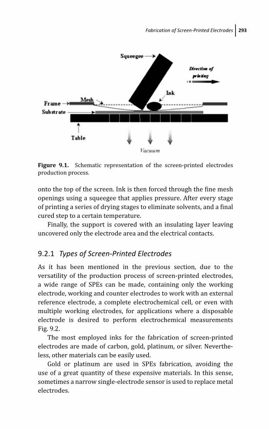
March 14, 2012 20:19 PSP Book - 9in x 6in 09-Ozsoz-c09
Fabrication of Screen-Printed Electrodes 293
Figure 9.1. Schematic representation of the screen-printed electrodes
production process.
onto the top of the screen. Ink is then forced through the fine mesh
openings using a squeegee that applies pressure. After every stage
of printing a series of drying stages to eliminate solvents, and a final
cured step to a certain temperature.
Finally, the support is covered with an insulating layer leaving
uncovered only the electrode area and the electrical contacts.
9.2.1 Types of Screen-Printed Electrodes
As it has been mentioned in the previous section, due to the
versatility of the production process of screen-printed electrodes,
a wide range of SPEs can be made, containing only the working
electrode, working and counter electrodes to work with an external
reference electrode, a complete electrochemical cell, or even with
multiple working electrodes, for applications where a disposable
electrode is desired to perform electrochemical measurements
Fig. 9.2.
The most employed inks for the fabrication of screen-printed
electrodes are made of carbon, gold, platinum, or silver. Neverthe-
less, other materials can be easily used.
Gold or platinum are used in SPEs fabrication, avoiding the
use of a great quantity of these expensive materials. In this sense,
sometimes a narrow single-electrode sensor is used to replace metal
electrodes.
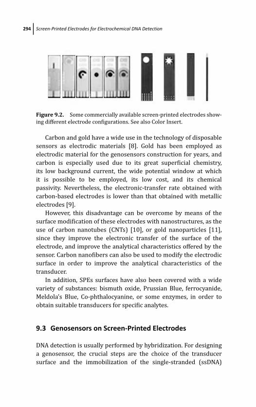
March 14, 2012 20:19 PSP Book - 9in x 6in 09-Ozsoz-c09
294 Screen-Printed Electrodes for Electrochemical DNA Detection
Figure 9.2. Some commercially available screen-printed electrodes show-
ing different electrode configurations. See also Color Insert.
Carbon and gold have a wide use in the technology of disposable
sensors as electrodic materials [8]. Gold has been employed as
electrodic material for the genosensors construction for years, and
carbon is especially used due to its great superficial chemistry,
its low background current, the wide potential window at which
it is possible to be employed, its low cost, and its chemical
passivity. Nevertheless, the electronic-transfer rate obtained with
carbon-based electrodes is lower than that obtained with metallic
electrodes [9].
However, this disadvantage can be overcome by means of the
surface modification of these electrodes with nanostructures, as the
use of carbon nanotubes (CNTs) [10], or gold nanoparticles [11],
since they improve the electronic transfer of the surface of the
electrode, and improve the analytical characteristics offered by the
sensor. Carbon nanofibers can also be used to modify the electrodic
surface in order to improve the analytical characteristics of the
transducer.
In addition, SPEs surfaces have also been covered with a wide
variety of substances: bismuth oxide, Prussian Blue, ferrocyanide,
Meldola’s Blue, Co-phthalocyanine, or some enzymes, in order to
obtain suitable transducers for specific analytes.
9.3 Genosensors on Screen-Printed Electrodes
DNA detection is usually performed by hybridization. For designing
a genosensor, the crucial steps are the choice of the transducer
surface and the immobilization of the single-stranded (ssDNA)
March 14, 2012 20:19 PSP Book - 9in x 6in 09-Ozsoz-c09
Genosensors on Screen-Printed Electrodes 295
probes onto electrode surface, because the molecular recognition
event typically occurs directly on the surface of the signal transducer.
The immobilization method will determine the sensitivity
and reproducibility of the genosensor. Several strategies for the
immobilization of ssDNA have been carried out and will be discussed
in section 9.3.2. The ssDNA probe immobilized on the transducer
surface recognizes its complementary (target) DNA sequence via
hybridization. The DNA duplex is then converted into an analytical
signal by the transducer. Different strategies for electrochemical
detection have been performed and are mainly divided in two
groups: methods using direct detection (those in which the intrinsic
electroactivity of DNA is involved) or indirect detection methods
(those which imply the use of labels).
Electrochemical detection of hybridization is mainly based
on the differences in the electrochemical behavior of the labels
with or without double-stranded (dsDNA) or single-stranded DNA
(ssDNA). The labels for hybridization detection can be enzymes,
anticancer agents, organic dyes, colorants, metal complexes, or
metal nanoparticles among others.
9.3.1 Electrochemical Detection of Hybridization Reaction
As it has been mentioned previously, there are a wide range of
possibilities for the electrochemical detection of the hybridization
reaction, and they can be divided into two types, direct or indirect
methods.
9.3.1.1 Direct transduction methods
Direct transduction relies on the measurement of physico-chemical
changes occurring at the recognition layer induced by hybridization
event. These methods are generally based on the oxidation
processes of guanine or adenine that occur in an oligonucleotide
when the hybridization reaction takes place [1–16]. This is because
the nucleobases present in the double strand are oxidized in a lower
extension than when they are forming a part of ssDNA, making the
analytical signal decrease, but at the same time the target strand
adds new bases increasing in part the analytical signal. This fact
March 14, 2012 20:19 PSP Book - 9in x 6in 09-Ozsoz-c09
296 Screen-Printed Electrodes for Electrochemical DNA Detection
gives rise to non-linear calibration plots. The alternative is to use
probes in which guanine bases have been replaced by inosine.
Then the analytical signal appearing with the hybridization and
background signals are negligible.
Another strategy to differentiate the signal of the single strand
from that of the double strand is based on the use of a protein
that binds specifically to the ssDNA, preventing the oxidation of the
guanine in single strands of DNA [16].
The great advantage of this type of detection is to avoid the use
of marks or indicators of hybridization, simplifying the experimental
procedure. However, the detection based on the electroactivity of
bases gives rise to a lack of sensitivity. Various proposals based
on the use of oxidation products of adenine as catalysts of NADH
oxidation [17], or those based in the use of mediators for the
oxidation of bases, with ruthenium complex [18, 19] or osmium
complex [20] have been proposed in order to get an amplification
of the signal and thereby improve the sensitivity.
However, these methods induce an irreversible process prevent-
ing multiuse and are limited by the adenine and guanine content.
9.3.1.2 Indirect transduction methods
Indirect transduction relies on the use of indicators or labels.
The first ones are based on the differences in the electrochemical
behavior of indicators that interact in a different extension with
dsDNA and ssDNA. The indicators for hybridization detection can
be anticancer agents, organic dyes, or metal complexes, and are not
generally covalently joined to DNA. The latter strategies include the
use of labels covalently joined to DNA such as ferrocene, enzymes, or
metal nanoparticles.
Use of indicators Indicators are electroactive compounds that
present different affinity for ssDNA and dsDNA; they used to be
anticarcinogenic agents, organic dyes, or metallic complexes.
Some metallic complexes like Ru(NH3)3+6 , [Fe(CN)6]3−/4−,
Co(phen)3+3 , or Ru(bpy)2+
3 , and some organic compounds like
methylene blue (MB) recognize the hybridization reaction. The
union takes place via electrostatic interaction with the hollows of the
March 14, 2012 20:19 PSP Book - 9in x 6in 09-Ozsoz-c09
Genosensors on Screen-Printed Electrodes 297
helix, or being inserted selectively and reversibly in the dsDNA. Their
use has been widely studied from the pioneering works of Millan and
Mikkelsen [21] in the early 90s. Most of them have been reviewed in
the work of Lucarelli [8]. Compounds that join the hollows of the
double helix have major affinity for dsDNA than for ssDNA, so the
signal due to the indicator oxidation increases when hybridization
takes place.
Other indicators, such as daunomycin or cobalt complexes, act
as intercalators. The changes in the area or peak potential of the
indicator oxidation process are used as analytical signal [22, 23].
Nevertheless, MB is another indicator that joins DNA by means
of intercalation, but generates minor reduction signals when it is
joined to dsADN than when joined to ssADN, because the specific
interaction of the MB with guanine bases is lower in the dsADN.
The hybridization indicators present the great advantage of
avoiding the processes of DNA labeling. Nevertheless, the discrim-
ination between single and double strand used to be not very good.
In addition, a general problem is the high backgrounds obtained,
due to unspecific adsorptions of indicators. However, if a negative
potential is applied to the electrodic surface once finished the assay,
these adsorptions can be repelled, diminishing the background
signals.
Use of labels There are two types of labels that join DNA covalently:
electroactive and non-electroactive labels.
The electroactive labels most used in genosensing design are
ferrocene and its derivates [24–27] (the reversible oxidation process
of ferrocene can be detected by means of several electrochemical
techniques), osmium complexes [28], platinum complexes [29],
gold complexes [30, 31], and metallic [32–36] or semiconductor
nanoparticles [37]. Among the last ones, gold nanoparticles are
the most used, their detection can be carried out by means of the
measurement of resistance or capacitance changes, usually after
an amplification procedure with silver, or by means of the anodic
stripping voltammetry of Au(III) obtained after the nanoparticle
oxidation Fig. 9.3.
An original approach consists in the use of ssDNA probes
labeled with an electroactive marker, the hybridization inducing
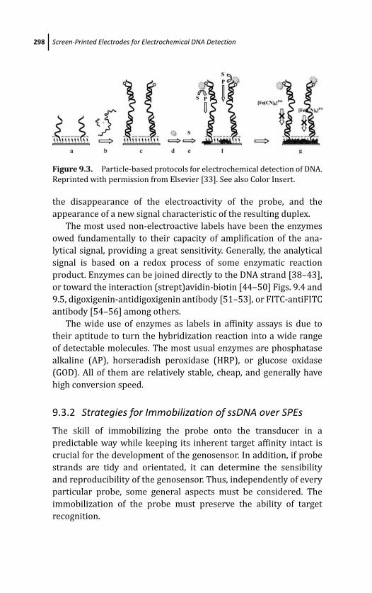
March 14, 2012 20:19 PSP Book - 9in x 6in 09-Ozsoz-c09
298 Screen-Printed Electrodes for Electrochemical DNA Detection
Figure 9.3. Particle-based protocols for electrochemical detection of DNA.
Reprinted with permission from Elsevier [33]. See also Color Insert.
the disappearance of the electroactivity of the probe, and the
appearance of a new signal characteristic of the resulting duplex.
The most used non-electroactive labels have been the enzymes
owed fundamentally to their capacity of amplification of the ana-
lytical signal, providing a great sensitivity. Generally, the analytical
signal is based on a redox process of some enzymatic reaction
product. Enzymes can be joined directly to the DNA strand [38–43],
or toward the interaction (strept)avidin-biotin [44–50] Figs. 9.4 and
9.5, digoxigenin-antidigoxigenin antibody [51–53], or FITC-antiFITC
antibody [54–56] among others.
The wide use of enzymes as labels in affinity assays is due to
their aptitude to turn the hybridization reaction into a wide range
of detectable molecules. The most usual enzymes are phosphatase
alkaline (AP), horseradish peroxidase (HRP), or glucose oxidase
(GOD). All of them are relatively stable, cheap, and generally have
high conversion speed.
9.3.2 Strategies for Immobilization of ssDNA over SPEs
The skill of immobilizing the probe onto the transducer in a
predictable way while keeping its inherent target affinity intact is
crucial for the development of the genosensor. In addition, if probe
strands are tidy and orientated, it can determine the sensibility
and reproducibility of the genosensor. Thus, independently of every
particular probe, some general aspects must be considered. The
immobilization of the probe must preserve the ability of target
recognition.
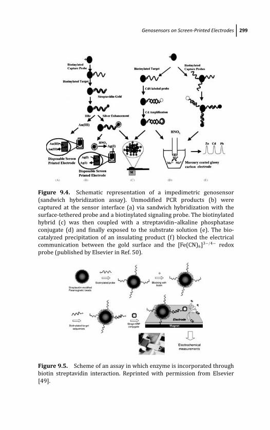
March 14, 2012 20:19 PSP Book - 9in x 6in 09-Ozsoz-c09
Genosensors on Screen-Printed Electrodes 299
Figure 9.4. Schematic representation of a impedimetric genosensor
(sandwich hybridization assay). Unmodified PCR products (b) were
captured at the sensor interface (a) via sandwich hybridization with the
surface-tethered probe and a biotinylated signaling probe. The biotinylated
hybrid (c) was then coupled with a streptavidin–alkaline phosphatase
conjugate (d) and finally exposed to the substrate solution (e). The bio-
catalyzed precipitation of an insulating product (f) blocked the electrical
communication between the gold surface and the [Fe(CN)6]3−/4− redox
probe (published by Elsevier in Ref. 50).
Figure 9.5. Scheme of an assay in which enzyme is incorporated through
biotin streptavidin interaction. Reprinted with permission from Elsevier
[49].

March 14, 2012 20:19 PSP Book - 9in x 6in 09-Ozsoz-c09
300 Screen-Printed Electrodes for Electrochemical DNA Detection
It is obvious that the immobilization protocol depends on the
transducer characteristics, nevertheless it is preferred to use robust
immobilization methods in order to avoid the probe desorption from
the sensor [57]. Thus, the retention in polymeric matrix, covalent
bonds on a functionalized surface, SAMs, and immobilization
through affinity reactions are the most successful methods at the
moment, because these strategies give place to an immobilization
across the ends of the probes in a tidy and orientated way.
In addition, these strategies allow to control the conformational
freedom of the probes and the space between chains by means
of the control of the superficial covering obtaining hybridization
efficiencies up to 100%.
The most of screen-printed electrodes employed as transducers
of genosensors are made of carbon or gold inks. Further sections
detail the most used probe immobilization strategies in these types
of electrodes.
9.3.2.1 Immobilization of ssDNA over carbon electrodes
Several strategies of DNA immobilization have been described onto
screen-printed carbon electrodes (SPCEs).
Although it is frequently used [58, 59], direct ssDNA immobiliza-
tion over bare carbon surface happens in a random and untidy way
due to the multiple interactions between the carbon surface and the
phosphate structure of DNA. DNA strands immobilized by physical
adsorption are not orientated and present a limited mobility, so the
hybridization reaction is hampered by stearic impediments Fig. 9.6.
Adsorption at controlled potential is generally carried out on
pretreated SPCEs [13, 15, 60, 61]. Nevertheless, in these cases the
probe strands are not totally accessible for their hybridization,
diminishing the genosensor efficiency.
Avidin [24], neutravidin [51], and streptavidin [54] have been
used to immobilize biotinylated DNA strands onto carbon electrodes
Fig. 9.7, but before immobilizing the probe the surface must be
blocked to avoid unspecific adsorptions like that of the components
of the genosensor.
Other strategies are based on the formation of a polymer, by
means of the electropolymerization of the probe modified with the
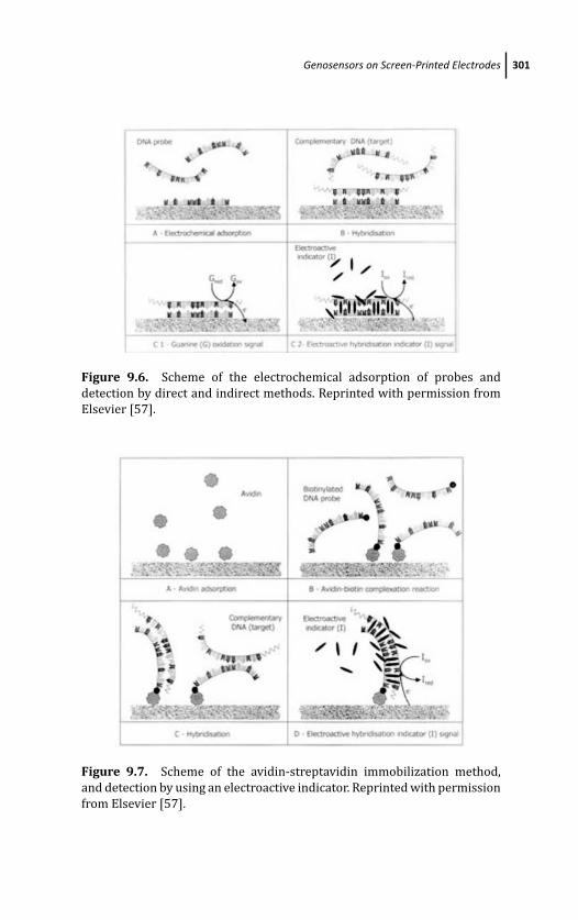
March 14, 2012 20:19 PSP Book - 9in x 6in 09-Ozsoz-c09
Genosensors on Screen-Printed Electrodes 301
Figure 9.6. Scheme of the electrochemical adsorption of probes and
detection by direct and indirect methods. Reprinted with permission from
Elsevier [57].
Figure 9.7. Scheme of the avidin-streptavidin immobilization method,
and detection by using an electroactive indicator. Reprinted with permission
from Elsevier [57].
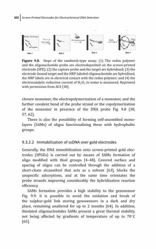
March 14, 2012 20:19 PSP Book - 9in x 6in 09-Ozsoz-c09
302 Screen-Printed Electrodes for Electrochemical DNA Detection
Figure 9.8. Steps of the sandwich-type assay: (1) The redox polymer
and the oligonucleotide probe are electrodeposited on the screen-printed
electrode (SPE); (2) the capture probe and the target are hybridized; (3) the
electrode-bound target and the HRP-labeled oligonucleotide are hybridized,
the HRP labels are in electrical contact with the redox polymer; and (4) the
electrocatalytic reduction current of H2O2 to water is measured. Reprinted
with permission from ACS [38].
chosen monomer, the electropolymerization of a monomer, and the
further covalent bond of the probe strand or the copolymerization
of the monomer in presence of the DNA probe Fig. 9.8 [38,
57, 62].
There is also the possibility of forming self-assembled mono-
layers (SAMs) of oligos functionalizing these with hydrophobic
groups.
9.3.2.2 Immobilization of ssDNA over gold electrodes
Generally, the DNA immobilization onto screen-printed gold elec-
trodes (SPGEs) is carried out by means of SAMs formation of
oligo modified with thiol groups [4–48]. Covered surface and
spacing of oligos can be controlled through the addition of a
short-chain alcanothiol that acts as a solvent [63], blocks the
unspecific adsorptions, and at the same time orientates the
probe strands improving considerably the hybridization reaction
efficiency.
SAMs formation provides a high stability to the genosensor
Fig. 9.9: it is possible to avoid the oxidation and break of
the sulphur-gold link storing genosensors in a dark and dry
place, remaining unaltered for up to 2 months [64]. In addition,
thiolated oligonucleotides SAMs present a great thermal stability,
not being affected by gradients of temperature of up to 70◦C
[65].
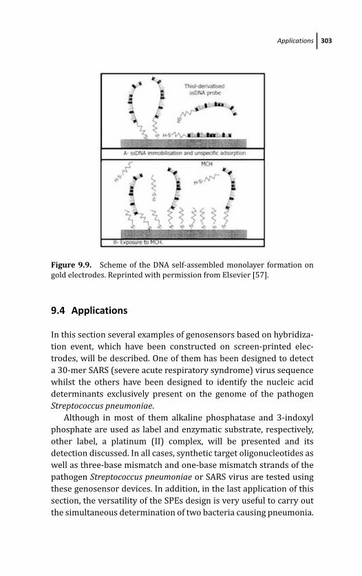
March 14, 2012 20:19 PSP Book - 9in x 6in 09-Ozsoz-c09
Applications 303
Figure 9.9. Scheme of the DNA self-assembled monolayer formation on
gold electrodes. Reprinted with permission from Elsevier [57].
9.4 Applications
In this section several examples of genosensors based on hybridiza-
tion event, which have been constructed on screen-printed elec-
trodes, will be described. One of them has been designed to detect
a 30-mer SARS (severe acute respiratory syndrome) virus sequence
whilst the others have been designed to identify the nucleic acid
determinants exclusively present on the genome of the pathogen
Streptococcus pneumoniae.
Although in most of them alkaline phosphatase and 3-indoxyl
phosphate are used as label and enzymatic substrate, respectively,
other label, a platinum (II) complex, will be presented and its
detection discussed. In all cases, synthetic target oligonucleotides as
well as three-base mismatch and one-base mismatch strands of the
pathogen Streptococcus pneumoniae or SARS virus are tested using
these genosensor devices. In addition, in the last application of this
section, the versatility of the SPEs design is very useful to carry out
the simultaneous determination of two bacteria causing pneumonia.
March 14, 2012 20:19 PSP Book - 9in x 6in 09-Ozsoz-c09
304 Screen-Printed Electrodes for Electrochemical DNA Detection
9.4.1 Enzymatic Genosensors on Streptavidin-ModifiedScreen-Printed Carbon Electrode
This section outlines the development of genosensors on screen-
printed carbon electrodes (SPCEs) for the identification of nucleic
acid determinants exclusively present in the genome of the
pathogen Streptococcus pneumoniae. Orientation of the strands in
the sensing phase is achieved by modifying the surface of the
electrode with streptavidin by physical adsorption followed by the
immobilization of biotinylated oligo probes. The physical adsorption
of streptavidin must be performed at a constant temperature above
the room temperature. Moreover, the electrode surface must be
previously electrochemically pretreated at an anodic potential in
acidic medium to improve its adsorptive properties. In this way,
reproducible, sensitive, and stable sensing phases are obtained [66].
The biotinylated oligo nucleic acid probes used in this work target
the pneumolysin (ply) gene. This target is randomly labeled with
the Universal Linkage System (ULS). This labeling system consists
of the use of a platinum (II) complex that acts as a coupling agent
between DNA strands and a label molecule, usually fluorescent. This
platinum complex is a monofunctional derivate of cisplatin (a potent
anticancer agent used in the treatment of a variety of tumors) that
binds to DNA at the N7 position of guanine with release of one Cl
ion per molecule of the complex. The label molecule used in this
study was fluorescein (FITC). Electrochemical detection is achieved
using two strategies. One of them is carried out using an anti-FITC
alkaline phosphatase-labeled antibody and 3-indoxyl phosphate (3-
IP) as enzymatic substrate of AP. The resulting enzymatic product is
indigo blue, an aromatic heterocycle insoluble in aqueous solutions.
Its sulfonation in acidic medium gives rise to indigo carmine IC, an
aqueous soluble compound that shows an electrochemical behavior
similar to indigo blue. Both 3-IP and IC have already been studied on
SPCEs [67, 68]. However, although these genosensors are stable and
sensitive devices for the detection of specific nucleic acid fragments,
the need of two additional steps to obtain the analytical signal
resulted in a large time-consuming analysis. This fact can be avoided
using the second strategy for detection. In this case the analytical
signal is directly obtained from platinum (II) complex, which is
March 14, 2012 20:19 PSP Book - 9in x 6in 09-Ozsoz-c09
Applications 305
deposited on the electrode surface. In presence of the platinum
on the electrode surface and after fixing an adequate potential in
acidic medium, the protons are catalytically reduced to hydrogen.
The current generated by this catalytic reduction can be measured
and increases with platinum concentration and consequently with
labeled target concentration.
Data presented here demonstrate the potential applicability
of SPCEs genosensors in the diagnosis of a human infectious
pulmonary disease. These electrochemical genosensors are stable
and sensitive devices for the detection of specific nucleic acid
fragments. Moreover, these devices allow the detection of a one-
base mismatch on the targets if adequate experimental conditions
are used
9.4.1.1 Genosensor design
Electrode pretreatment: 50 μL of 0.1 M H2SO4 are dropped on the
SPCEs and an anodic current of + 3.0 μA is applied for 2 minutes.
Then, the electrodes are washed using 0.1 M Tris buffer pH 7.2.
Adsorption of streptavidin: an aliquot of 10 μL of a 1× 1−5 M
streptavidin solution is left on the electrode surface overnight at
4◦C. Then, the electrode is washed with 0.1 M Tris buffer pH 7.2 to
remove the excess of protein.
Blocking step: free surface sites are blocked by placing a drop of
40 μL of a 2% (w/v) solution of BSA for 15 minutes followed by a
washing step with 0.1 M Tris pH 7.2 buffer containing 1% of BSA.
Immobilization of oligonucleotide probes onto the electrode
surface: 40 μL of 3’-biotynilated oligonucleotide probes (0.5 ng/mL)
is left on the electrode surface for 15 minutes. Finally, the
electrodes are rinsed with 2 × SSC buffer pH 7.2 containing 1% of
BSA.
Hybridization is performed at room temperature placing 30 μL
of FITC-labeled oligonucleotide target solutions in 2 × SSC buffer
pH 7.2, containing 1% of BSA, on the surface of the genosensor for
45 minutes and then rinsing with 0.1 M Tris pH 7.2 buffer containing
1% of BSA. The methodology used to detect one-base mismatch
strands is similar, but in this case 25% formamide is included in the
hybridization buffer.
March 14, 2012 20:19 PSP Book - 9in x 6in 09-Ozsoz-c09
306 Screen-Printed Electrodes for Electrochemical DNA Detection
9.4.1.2 Analytical signal recording
Two strategies are performed to detect the hybridization event:
enzymatic detection and electrocatalytic detection. The following
steps are carried out:
Enzymatic detection: Reaction with antibody anti-FITC AP conju-
gate (Ab-AP): an aliquot of 40 μL of Ab-AP solution (1/100 dilution)
is dropped on the genosensor device for 60 minutes. Then a washing
step with 0.1 M Tris buffer pH 9.8, containing 1% BSA, is carried out.
Enzymatic reaction: An aliquot of 30 μL of 6 mM 3-IP is deposited
on the electrode surface for 20 minutes. After that, the reaction
is stopped by adding 4 μL of fuming sulphuric acid and 10 μL of
ultra-pure water. In this step, the corresponding indigo product is
converted to its parent hydrosoluble compound IC.
Analytical signal recording: The SPCEs are held at a potential of
−0.25V for 25 s, and then, a cyclic voltammogram is recorded from
0.25 to +0.20V at a scan rate of 50 mV/s. The anodic peak current is
measured in all experiments.
Electrocatalytic detection: A 50 μL portion of 0.2 M HCl solution
is dropped on the electrode surface and the electrode is held at a
potential of +1.35V for 1 minute. Then, the chronoamperometric
detection is performed at −1.40 V, recording the electric current
generated for 5 minutes.
Figure 9.10 shows the scheme of the genosensor device and
the analytical signals obtained with electrocatalytic detection (Fig.
9.10A) and enzymatic detection (Fig. 9.10B).
Moreover, the significance of the attachment of biotinylated
oligonucleotide probes through the streptavidin/biotin interaction
has been tested in a previous work [15]. When a double-labeled
(biotin and fluorescein) poly-T was attached to the electrode surface
through the streptavidin/biotin interaction, the peak currents were
much higher than those obtained when it was accumulated on
the electrode surface by physical adsorption. This fact means that
streptavidin/biotin interaction allows to attach and orient the
oligonucleotide strands on electrode surface, whereas the direct
adsorption of the oligonucleotide on the electrode surface results
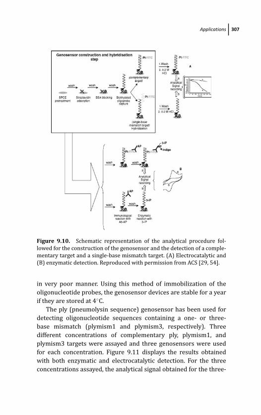
March 14, 2012 20:19 PSP Book - 9in x 6in 09-Ozsoz-c09
Applications 307
Figure 9.10. Schematic representation of the analytical procedure fol-
lowed for the construction of the genosensor and the detection of a comple-
mentary target and a single-base mismatch target. (A) Electrocatalytic and
(B) enzymatic detection. Reproduced with permission from ACS [29, 54].
in very poor manner. Using this method of immobilization of the
oligonucleotide probes, the genosensor devices are stable for a year
if they are stored at 4◦C.
The ply (pneumolysin sequence) genosensor has been used for
detecting oligonucleotide sequences containing a one- or three-
base mismatch (plymism1 and plymism3, respectively). Three
different concentrations of complementary ply, plymism1, and
plymism3 targets were assayed and three genosensors were used
for each concentration. Figure 9.11 displays the results obtained
with both enzymatic and electrocatalytic detection. For the three
concentrations assayed, the analytical signal obtained for the three-
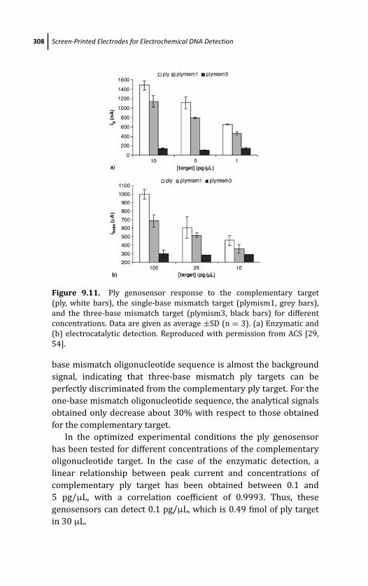
March 14, 2012 20:19 PSP Book - 9in x 6in 09-Ozsoz-c09
308 Screen-Printed Electrodes for Electrochemical DNA Detection
Figure 9.11. Ply genosensor response to the complementary target
(ply, white bars), the single-base mismatch target (plymism1, grey bars),
and the three-base mismatch target (plymism3, black bars) for different
concentrations. Data are given as average ±SD (n = 3). (a) Enzymatic and
(b) electrocatalytic detection. Reproduced with permission from ACS [29,
54].
base mismatch oligonucleotide sequence is almost the background
signal, indicating that three-base mismatch ply targets can be
perfectly discriminated from the complementary ply target. For the
one-base mismatch oligonucleotide sequence, the analytical signals
obtained only decrease about 30% with respect to those obtained
for the complementary target.
In the optimized experimental conditions the ply genosensor
has been tested for different concentrations of the complementary
oligonucleotide target. In the case of the enzymatic detection, a
linear relationship between peak current and concentrations of
complementary ply target has been obtained between 0.1 and
5 pg/μL, with a correlation coefficient of 0.9993. Thus, these
genosensors can detect 0.1 pg/μL, which is 0.49 fmol of ply target
in 30 μL.
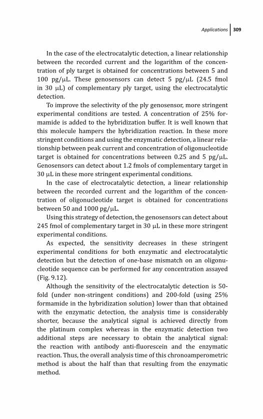
March 14, 2012 20:19 PSP Book - 9in x 6in 09-Ozsoz-c09
Applications 309
In the case of the electrocatalytic detection, a linear relationship
between the recorded current and the logarithm of the concen-
tration of ply target is obtained for concentrations between 5 and
100 pg/μL. These genosensors can detect 5 pg/μL (24.5 fmol
in 30 μL) of complementary ply target, using the electrocatalytic
detection.
To improve the selectivity of the ply genosensor, more stringent
experimental conditions are tested. A concentration of 25% for-
mamide is added to the hybridization buffer. It is well known that
this molecule hampers the hybridization reaction. In these more
stringent conditions and using the enzymatic detection, a linear rela-
tionship between peak current and concentration of oligonucleotide
target is obtained for concentrations between 0.25 and 5 pg/μL.
Genosensors can detect about 1.2 fmols of complementary target in
30 μL in these more stringent experimental conditions.
In the case of electrocatalytic detection, a linear relationship
between the recorded current and the logarithm of the concen-
tration of oligonucleotide target is obtained for concentrations
between 50 and 1000 pg/μL.
Using this strategy of detection, the genosensors can detect about
245 fmol of complementary target in 30 μL in these more stringent
experimental conditions.
As expected, the sensitivity decreases in these stringent
experimental conditions for both enzymatic and electrocatalytic
detection but the detection of one-base mismatch on an oligonu-
cleotide sequence can be performed for any concentration assayed
(Fig. 9.12).
Although the sensitivity of the electrocatalytic detection is 50-
fold (under non-stringent conditions) and 200-fold (using 25%
formamide in the hybridization solution) lower than that obtained
with the enzymatic detection, the analysis time is considerably
shorter, because the analytical signal is achieved directly from
the platinum complex whereas in the enzymatic detection two
additional steps are necessary to obtain the analytical signal:
the reaction with antibody anti-fluorescein and the enzymatic
reaction. Thus, the overall analysis time of this chronoamperometric
method is about the half than that resulting from the enzymatic
method.
March 14, 2012 20:19 PSP Book - 9in x 6in 09-Ozsoz-c09
310 Screen-Printed Electrodes for Electrochemical DNA Detection
Figure 9.12. Ply genosensor responses for different concentrations of
complementary target (ply, white bars) and the single-base mismatch
target (plymisms1, grey bars) when 25% formamide is included in the
hybridization buffer. Data are given as average ±SD (n = 3). (a) Enzymatic
and (b) electrocatalytic detection. Reproduced with permission from ACS
[29, 54].
9.4.2 Alkaline Phosphatase-Catalyzed Silver Deposition forElectrochemical Detection
In this section a new substrate solution is described that combines
an indoxyl compound, 3-indoxyl phosphate (3-IP), and silver ions.
The resulting enzymatic product of 3-IP is indigo blue, an aromatic
heterocycle insoluble in aqueous solutions. Two strategies can be
carried out to detect the product: its sulfonation in acidic medium,
giving rise to indigo carmine (IC), or its solubilization in basic
medium and in the presence of dithionite salt, giving rise to
leucoindigo. The main drawback of these methodologies is that, in all
cases, it is necessary to add a step for detection after the enzymatic
reaction and the use of aggressive agents such as concentrated
March 14, 2012 20:19 PSP Book - 9in x 6in 09-Ozsoz-c09
Applications 311
sulfuric acid or sodium dithionite, respectively. The substrate
proposed here overcomes these drawbacks and, moreover, improves
the sensitivity of the methodology. To demonstrate the better
sensitivity obtained with this substrate, an enzymatic genosensor on
SPCEs for the identification of nucleic acid determinants exclusively
present on the genome of the pathogen Streptococcus pneumoniaehas been developed. The different steps of this genosensor have
been optimized in a previous work [54]. Orientation of the strands
in the sensing phase is achieved by modifying the surface of the
electrode with streptavidin by physical adsorption followed by
the immobilization of biotinylated oligo probe. The biotinylated
oligonucleic acid probe used in this work targets the autolysin
(lytA) gene. This target is randomly labeled with the Universal
Linkage System (ULS). This system binds to DNA at the N7 position
of guanine, resulting in the attachment of a label molecule to
the DNA. The label molecule used in this study was fluorescein
(FITC). Electrochemical detection is achieved with an anti-FITC
alkaline phosphatase-labeled antibody (Ab-AP) and using substrate
proposed here, 3-IP/Ag+.
9.4.2.1 Genosensor design
The electrode pretreatment was carried out by applying an anodic
current of +5 μA for 2 minutes in a 40 μL aliquot of 0.1 M
H2SO4 Then, the electrodes were washed using 0.1 M Tris-HNO3
buffer pH 7.2. The adsorption of streptavidin onto the electrode
surface was performed leaving an aliquot of 10 μL of a 1× 10⁻⁵ M
streptavidin solution on the electrode surface between overnight at
4◦C. Then, the electrode was washed with 0.1 M Tris-HNO3 buffer pH
7.2 to remove the excess of protein.
Free surface sites were blocked placing a drop of 40 μL of a
2% (w/v) solution of BSA for 15 minutes followed by a washing
step with 0.1 M Tris-HNO3 pH 7.2 buffer containing 1% BSA.
Immobilization of the probe was performed dropping 40 μL of 3’-
biotinylated oligonucleotide probe (0.5 ng/μL) for 15 minutes. Then,
the electrodes were rinsed with 2 × SSC buffer pH 7.2 containing
1% BSA. After that, the hybridization was performed at room
temperature placing 30 μL of FITC-labeled oligonucleotide target

March 14, 2012 20:19 PSP Book - 9in x 6in 09-Ozsoz-c09
312 Screen-Printed Electrodes for Electrochemical DNA Detection
solutions in 2× SSC buffer pH 7.2, containing 1% BSA, on the surface
of the genosensor for 45 minutes and then rinsing with 0.1 M Tris-
HNO3 pH 7.2 buffer containing 1% BSA. Then, a reaction with Ab-
AP was performed dropping aliquots of 40 μL of Ab-AP solutions
(1/100 dilution) on the genosensor device for 60 minutes. After a
washing step with 0.1 M Tris-HNO3 buffer pH 9.8, containing 1%
BSA, the enzymatic reaction was carried out by dropping an aliquot
of 35 μL of a mixture of 5.6 mM 3-IP and 0.4 mM silver nitrate
solutions for 20 minutes, protected from light. Then, the SPCE was
held at −0.20 V for 5 s, and a cyclic voltammogram was recorded
(in the same enzymatic reaction medium) from −0.20 to 0.50 V at a
scan rate of 50 mV/s to obtain the analytical signal.
9.4.2.2 Results
Once the procedure was optimized, an enzymatic genosensor for the
identification of a nucleic acid determinant exclusively present on
the genome of the pathogen S. pneumoniae was developed. This DNA
sensor has been described and optimized by our research group in
the previous section. In this work, for the electrochemical detection
step, 3-IP was used as substrate and then sulfuric acid was added to
generate an electroactive compound termed indigo carmine, which
is quantified by cyclic voltammetry.
In this case, by combining the 3-IP with silver ions, the metallic
silver deposited on the electrode surface is detected directly without
the need of any more steps to obtain the analytical signal. Thus, the
use of sulfuric acid is avoided.
Using the optimized experimental conditions, the response of the
genosensor formed with 3’-biotinylated autolysin gene lytA probe
for different concentrations of the complementary oligonucleotide
target has been evaluated. Figure 9.13 shows the calibration
plot (Fig. 9.13A) and the voltammograms corresponding to each
concentration as well as the voltammogram corresponding to the
noncomplementary target for the highest concentration assayed
(Fig. 9.13B).
A linear relationship between peak current and concentration of
complementary lytA target is obtained between 7 and 700 fg/μL,
with a correlation coefficient of 0.9995. The reproducibility of the

March 14, 2012 20:19 PSP Book - 9in x 6in 09-Ozsoz-c09
Applications 313
Figure 9.13. (A) lytA genosensor responses for different concentrations
of complementary target. Data are given as average ±SD (n = 3). (B)
Cylic voltammograms corresponding to the background (700 fg/μL of
noncomplementary target) and to each concentration of complementary
target of the linear calibration curve. Reproduced with permission from ACS
[56].
analytical signal for the concentrations of complementary target
assayed is shown with error bars. It is composed between 4 and 10
in terms of percent RSD.
Also, comparing linear ranges obtained for target autolysin
through both methodologies, the sensitivity of the assay is improved
by at least 1 order of magnitude.
Thus, this genosensor can detect 7 fg/μL, approximately 14-
fold less than the concentration detected when the enzymatic
reaction was carried out only with 3-IP [54]. Also, the use of
3-IP as the enzymatic substrate allows a better control of the
March 14, 2012 20:19 PSP Book - 9in x 6in 09-Ozsoz-c09
314 Screen-Printed Electrodes for Electrochemical DNA Detection
silver deposition versus the use of another substrate such as p-
aminophenyl phosphate that is more unstable and produces higher
background signals.
Moreover, the hybridization reaction with noncomplementary
target does not occur for all concentrations assayed (see the
voltammogram in Fig. 9.13B for the highest concentration of
noncomplementary target assayed, 700 fg/μL). This fact shows that
non-specific adsorptions are not observed. Regarding the selectivity
of the genosensor, this system has been studied in the previous
section and this is able to discriminate one-base mismatched
strands.
9.4.3 Genosensor for SARS Virus Detection Based on GoldNanostructured Screen-Printed Carbon Electrode
In this section, a DNA hybridization assay with enzymatic electro-
chemical detection was carried out on a disposable gold nanos-
tructured screen-printed carbon electrode (SPCnAuE), which allows
working with small volumes. Gold nanoparticles (NPs) which are
formed in situ by applying a constant current intensity during a fixed
time act as an immobilization and transduction surface. Although
thick gold substrates are reported in the literature for enzymatic
DNA detection (screen-printed gold electrodes [46], 2 mm thick film
gold electrodes [66], or gold disk electrodes [69]), gold NPs have
been unusually used as electrochemical transducers, despite of their
widespread use as DNA labels due to the electrochemical properties
of gold NPs [70].
The sequence chosen as target is included in the 29 751-base
genome of the SARS (severe acute respiratory syndrome)-associated
coronavirus. A 30-mer oligonucleotide with bases comprised
between numbers 29 218 and 29 247, both included, was chosen.
This is the causative agent of an outbreak of atypical pneumonia,
first identified in Guangdong Province, China, that has spread to
several countries. The sequence corresponds to a gene that encodes
the nucleocapsid protein (422 amino acids), specifically a short
lysine-rich region that appears to be unique to SARS and suggestive
of a nuclear localization signal.
March 14, 2012 20:19 PSP Book - 9in x 6in 09-Ozsoz-c09
Applications 315
9.4.3.1 Gold nanostructuration of screen-printed carbonelectrodes
Gold nanostructures were in situ generated over SPCEs (SPCnAuEs)
applying a constant current intensity of −5 μA for 2 minutes in a
0.1 mM acidic solution of AuCl−4 . After that, and in the same medium,
a potential of +0.1 V was applied during 2 minutes, in order to
desorb hydrogen.
9.4.3.2 Genosensor design
The formation of the sensing phase was performed by dropping
20 μL of 3’-thiolated oligonucleotide probe 10 nM for 20 minutes
and after rinsing with 0.1 M Tris-HNO3 pH 7.2, a blocking step
with casein (2%) was carried out. Then, the electrodes were rinsed
with 2 × SSC buffer pH 7.2 containing 1% BSA. After that, the
hybridization was performed at room temperature placing 40 μL
of 3’-biotinylated oligonucleotide target solutions in 2 × SSC buffer
pH 7.2, containing 1% BSA, on the surface of the genosensor for 1
hour and then rinsing with 0.1 M Tris-HNO3 pH 7.2 buffer containing
2 mM Mg(NO3)2. Then, a reaction with alkaline phosphatase labeled
streptavidin (S-AP) was performed dropping aliquots of 40 μL of
S-AP solutions (5 × 10⁻¹⁰ M) on the genosensor device for 60
minutes. Finally, after a washing step with 0.1 M Tris-HNO3 buffer
pH 9.8, containing 20 mM Mg(NO3)2, the enzymatic reaction of the
substrate, a mixture of 3-indoxyl phosphate (3-IP) and silver nitrate,
was performed. In this reaction, 3-IP produces a compound able to
reduce silver ions in solution into a metallic deposit. The deposited
silver is electrochemically stripped into solution and measured by
anodic stripping voltammetry giving place to the analytical signal
Fig. 9.14.
9.4.3.3 Results
Adsorption of thiolated probes was studied, in this sense adsorption
time and probe concentration were tested. Results obtained shown
that 20 minutes was enough time to reach a plateau in the analytical
signal, and probe concentration was fixed in 10 nM, because
higher concentrations resulted in a decrease in the analytical signal.
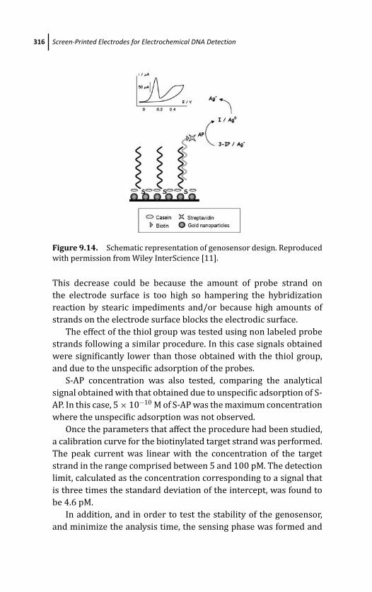
March 14, 2012 20:19 PSP Book - 9in x 6in 09-Ozsoz-c09
316 Screen-Printed Electrodes for Electrochemical DNA Detection
Figure 9.14. Schematic representation of genosensor design. Reproduced
with permission from Wiley InterScience [11].
This decrease could be because the amount of probe strand on
the electrode surface is too high so hampering the hybridization
reaction by stearic impediments and/or because high amounts of
strands on the electrode surface blocks the electrodic surface.
The effect of the thiol group was tested using non labeled probe
strands following a similar procedure. In this case signals obtained
were significantly lower than those obtained with the thiol group,
and due to the unspecific adsorption of the probes.
S-AP concentration was also tested, comparing the analytical
signal obtained with that obtained due to unspecific adsorption of S-
AP. In this case, 5 × 10⁻¹⁰ M of S-AP was the maximum concentration
where the unspecific adsorption was not observed.
Once the parameters that affect the procedure had been studied,
a calibration curve for the biotinylated target strand was performed.
The peak current was linear with the concentration of the target
strand in the range comprised between 5 and 100 pM. The detection
limit, calculated as the concentration corresponding to a signal that
is three times the standard deviation of the intercept, was found to
be 4.6 pM.
In addition, and in order to test the stability of the genosensor,
and minimize the analysis time, the sensing phase was formed and

March 14, 2012 20:19 PSP Book - 9in x 6in 09-Ozsoz-c09
Applications 317
Figure 9.15. Analytical signals obtained for 50 pM of biotinylated target,
using a genosensor fresh prepared (A), a genosensor in which thiolated
probes were immobilized and stored at 4◦C overnight (B), and a genosensor
stored at 4◦C where both, probe and blocking agent were immobilized.
Reproduced with permission from Wiley InterScience [11].
stored at 4◦C. With this aim, SPCnAuEs were modified following the
procedure previously described and stored at 4◦C overnight.
Results obtained are displayed in Fig. 9.15, and show that the
analytical signal due to a biotinylated target concentration of 50 pM
results incremented in about 15%. However, when the blocking
step is also carried out prior to the storage of the sensing phase,
the analytical signal due to the same concentration of biotinylated
target gives rise to a decrease of about 20% of the analytical
signal.
With SPCnAuEs modified with the probe strand and stored at
4◦C overnight, a calibration plot was recorded. A linear relationship
of the analytical signal with the concentration of the biotinylated
target strand in the range comprised between 2.5 and 50 pM
was obtained. The detection limit, calculated as the concentration
corresponding to a signal that is three times the standard deviation
of the intercept, was found to be 2.5 pM. The linear range obtained
with this methodology is closer than that obtained when the sensing
phase is freshly prepared, but its sensibility is around three times
that obtained with the former methodology. Moreover, storage of the
sensing phase permits to minimize the analysis time and increases
the possibility of storing the genosensors and using them when
necessary.
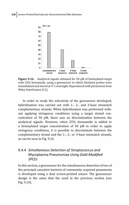
March 14, 2012 20:19 PSP Book - 9in x 6in 09-Ozsoz-c09
318 Screen-Printed Electrodes for Electrochemical DNA Detection
Figure 9.16. Analytical signals obtained for 50 pM of biotinylated target
with 25% formamide, using a genosensor in which thiolated probes were
immobilized and stored at 4◦C overnight. Reproduced with permission from
Wiley InterScience [11].
In order to study the selectivity of the genosensor developed,
hybridization was carried out with 1-, 2-, and 3-base mismatch
complementary strands. When hybridization was performed with-
out applying stringency conditions using a target strand con-
centration of 50 pM, there was no discrimination between the
analytical signals. However, when 25% formamide is added to
a biotinylated target concentration of 50 pM in order to apply
stringency conditions, it is possible to discriminate between the
complementary strand and the 1-, 2-, or 3-base mismatch strands,
as can be seen in Fig. 9.16.
9.4.4 Simultaneous Detection of Streptococcus andMycoplasma Pneumoniae Using Gold-ModifiedSPCEs
In this section, a genosensor for the simultaneous detection of two of
the principal causative bacteria of community acquired pneumonia
is developed using a dual screen-printed sensor. The genosensor
design is the same that the used in the previous section (see
Fig. 9.14).

March 14, 2012 20:19 PSP Book - 9in x 6in 09-Ozsoz-c09
Applications 319
Figure 9.17. Commercial dual screen-printed carbon electrode. See also
Color Insert.
The target sequences have been chosen so that the same primer
is able to generate the PCR products of both bacteria. Thus, with
a unique screen-printed strip it is possible to identify the causing
bacteria of the disease.
The dual screen-printed electrode used in this section is shown
in Fig. 9.17.
9.4.4.1 Genosensor design
As it has been commented, the genosensor design is the same that
was used in section 9.4.3.2, with some variations
Gold nanostructuration is carried out by applying a constant
current of −5 μA for 2 minutes in an acidic medium containing
AuCl4− 1 mM. Then the electrode is generously rinsed with water.
A 4 μL aliquot of 50 nM thiolated probes is dropped in each
working electrode for 10 minutes. One working electrode supports
the probe corresponding to S. pneumoniae, and the other supports
the probe corresponding to M. pneumoniae. Then, the electrode is
rinsed with 0.1 M Tris-HNO3 buffer pH 7.2, and a blocking step is
carried out with a 40-μL aliquot of casein 2% for 20 minutes and
rinsed with 0.1 M Tris buffer pH 7.2
Hybridization step is carried out at room temperature in 2 × SSC
buffer by dropping a 40 μL aliquot of the biotinylated target for 1
hour and rinsing with Tris buffer pH 7.2. After that 40 μL of 5× 10⁻¹⁰
M S-AP are dropped on the electrode for 1 hour. Then the electrode
is rinsed with Tris buffer pH 9.8 and enzymatic reaction with 3-IP
and silver ions, and detection step is carried out as mentioned in
previous sections.
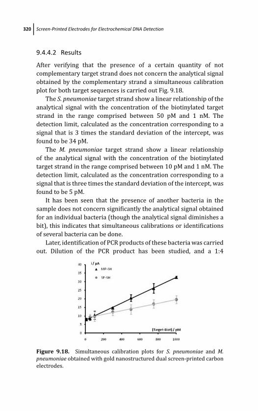
March 14, 2012 20:19 PSP Book - 9in x 6in 09-Ozsoz-c09
320 Screen-Printed Electrodes for Electrochemical DNA Detection
9.4.4.2 Results
After verifying that the presence of a certain quantity of not
complementary target strand does not concern the analytical signal
obtained by the complementary strand a simultaneous calibration
plot for both target sequences is carried out Fig. 9.18.
The S. pneumoniae target strand show a linear relationship of the
analytical signal with the concentration of the biotinylated target
strand in the range comprised between 50 pM and 1 nM. The
detection limit, calculated as the concentration corresponding to a
signal that is 3 times the standard deviation of the intercept, was
found to be 34 pM.
The M. pneumoniae target strand show a linear relationship
of the analytical signal with the concentration of the biotinylated
target strand in the range comprised between 10 pM and 1 nM. The
detection limit, calculated as the concentration corresponding to a
signal that is three times the standard deviation of the intercept, was
found to be 5 pM.
It has been seen that the presence of another bacteria in the
sample does not concern significantly the analytical signal obtained
for an individual bacteria (though the analytical signal diminishes a
bit), this indicates that simultaneous calibrations or identifications
of several bacteria can be done.
Later, identification of PCR products of these bacteria was carried
out. Dilution of the PCR product has been studied, and a 1:4
Figure 9.18. Simultaneous calibration plots for S. pneumoniae and M.pneumoniae obtained with gold nanostructured dual screen-printed carbon
electrodes.
March 14, 2012 20:19 PSP Book - 9in x 6in 09-Ozsoz-c09
References 321
dilution was determined as optimum for the bacteria identification.
Identification of PCR products has been realized successfully in 90%
of cases.
9.5 Conclusion
As it has been shown in previous sections, the use of screen-printed
electrodes as support for genosensor devices offers enormous
opportunities for their application in molecular diagnosis. The
technologies used in the fabrication of these electrodes allow the
mass production of reproducible, inexpensive and mechanically
robust strip solid electrodes. Other important advantages of these
electrodes are the possibility of miniaturization as well as their easy
manipulation in a disposable manner and therefore the use of small
volumes, diminishing the cost of the analysis. This is an important
issue that makes this methodology for the detection of DNA more
attractive.
Moreover, in addition, the versatility of design of screen-printed
electrodes allows to carry out a simultaneous detection of several
DNA sequences in the same analysis.
Very sensitive methods are always required for DNA sensing.
Although enough sensitivity to avoid PCR amplification has been
achieved by use of enzymatic labels or metal tags, most of the assays
routinely start with a PCR or other biochemical amplification. More-
over, although label-free formats are used, most of the strategies
followed to obtain the analytical signal involve several washing steps
and need the use of labeled reagents (or labeling procedures) or
indicators, which complicates the assay performance.
Sensitive methodologies can also be obtained through the
electrodic modification with a nanostructured material, taking
advantage of the special characteristics that nanostructuration
offers.
References
1. F. R. R. Teles and L. P. Fonseca, Trends in DNA biosensors, Talanta77(2), 606–623 (2008).
March 14, 2012 20:19 PSP Book - 9in x 6in 09-Ozsoz-c09
322 Screen-Printed Electrodes for Electrochemical DNA Detection
2. E. Palecek, in Progress in Nucleic Acids Research and Molecular Biology(J. N. Davidson and W. E. Cohn, eds.), Academic Press, New York, vol. 9,
p. 31 (1969).
3. J. J. Gooding, Electrochemical DNA hybridization biosensors, Electro-analysis 14(17), 1149–1156 (2002).
4. E. Palecek, Past, present and future of nucleic acid electrochemistry,
Talanta 56(5), 809–819 (2002).
5. Y. Ye and H. Ju, DNA electrochemical behaviour, recognition and
sensing by combining with PCR technique, Sensors 3, 128–145 (2003)
6. G. A. Rivas, M. L. Pedano, and N. F. Ferreyra, Electrochemical biosensors
for sequence-specific DNA detection, Anal. Lett. 38(15), 2653–2703
(2005)
7. A. Heller and B. Feldmann, Electrochemical glucose sensors and their
application in diabetes management, Chem. Rev. 108(7), 2482–2505
(2008).
8. F. Lucarelli, G. Marrazza, A. P. F. Turner, and M. Mascini, Carbon and
gold electrodes as electrochemical transducers for DNA hybridisation
sensors, Biosens. Bioelectron. 19(6), 515–530 (2004)
9. R. L. McCreery, Carbon electrodes: structural effects on electron
transfer kinetics, in Electroanalytical Chemistry (A. J. Bard, ed.), Marcel
Dekker, New York, p. 18 (1991).
10. P. Fanjul-Bolado, P. Queipo, P. J. Lamas-Ardisana, and A. Costa-Garcia,
Manufacture and evaluation of carbon nanotube modified screen-
printed electrodes as electrochemical tools, Talanta 74(3), 427–433
(2007).
11. G. Martınez-Paredes, M. B. Gonzalez-Garcıa and A. Costa-Garcıa,
Genosensor for SARS virus detection based on gold nanostructured
screen-printed carbon electrodes, Electroanalysis 21(3–5), 379—385
(2009).
12. J. Wang and A. N. Kawde, Pencil-based renewable biosensor for label-
free electrochemical detection of DNA hybridization, Anal. Chim. Acta431(2), 219–224 (2001).
13. F. Lucarelli, G. Marrazza, I. Palchetti, S. Cesaretti, and M. Mascini,
Coupling of an indicator-free electrochemical DNA biosensor with
polymerase chain reaction for the detection of DNA sequences related
to the apolipoprotein E, Anal. Chim. Acta 469(1), 93–99 (2002).
14. A. Erdem, I. Pividori, M. del Valle, and S. Alegret, Rigid carbon
composites: a new transducing material for label-free electrochemical
genosensing, J. Electroanal. Chem. 567(1), 29–37 (2004).
March 14, 2012 20:19 PSP Book - 9in x 6in 09-Ozsoz-c09
References 323
15. M. Mascini, M. del Carlo, M. Minunni, B. Chen, and D. Compagnone,
Identification of mammalian species using genosensors, Bioelectro-chemistry 67(2), 163–169 (2005).
16. K. Kerman, Y. Morita, Y. Takamura, and E. Tamiya, Escherichia coli
single-strand binding protein-DNA interactions on carbon nanotube-
modified electrodes from a label-free electrochemical hybridization
sensor, Anal. Bioanal. Chem. 381(6), 1114–1121 (2005).
17. P. de-los-Santos-Alvarez, M. J. Lobo-Castanon, A. J. Miranda-Ordieres,
and P. Tunon-Blanco, Voltammetric determination of underivatized
oligonucleotides on graphite electrodes based on their oxidation
products, Anal. Chem. 74(14), 3342–3347 (2002).
18. P. M. Armistead and H. H. Thorp, Modification of indium tin oxide
electrodes with nucleic acids: detection of attomole quantities of
immobilized DNA by electrocatalysis, Anal. Chem. 72(16), 3764–3777
(2002).
19. N. D. Popovich, A. E. Eckhardt, J. C. Mikulecky, M. E. Napier, and R. S.
Thomas, Electrochemical sensor for detection of unmodified nucleic
acids, Talanta 56(5), 821–828 (2002).
20. M. R. Gore, V. A. Szalai, P. A. Ropp, I. V. Yang, J. S. Silverman, and H.
H. Thorp, Detection of attomole quantitites of DNA targets on gold
microelectrodes by electrocatalytic nucleobase oxidation, Anal. Chem.75(23), 6586–6592 (2003).
21. K. M. Millan and S. R. Mikkelsen, Sequence-selective biosensor for DNA
based on electroactive hybridization indicators, Anal. Chem. 65(17),
2317–2323 (1993).
22. J. Wang, G. Rivas, and X. Cai, Screen printed electrochemical hybridiza-
tion biosensor for the detection of DNA sequences from Escherichia colipathogen, Electroanalysis 9(5), 395–398 (1997).
23. G. Marrazza, I. Chianella, and M. Mascini, Disposable DNA electrochem-
ical sensor for hybridisation detection, Biosens. Bioelectron. 14(1), 43–
51 (1999).
24. L. Authier, C. Grossiord, P. Brossier, and B. Limoges, Gold nanoparticle-
based quantitative electrochemical detection of amplified human
cytomegalovirus DNA using disposable microband electrodes, Anal.Chem. 73(18), 4450–4453 (2001).
25. H. Cai, C. Su, P. He, and Y. Fang, Colloid Au-enhanced DNA immobi-
lization for the electrochemical detection of sequence-specific DNA, J.Electroanal. Chem. 510(1–2), 78–85 (2001).

March 14, 2012 20:19 PSP Book - 9in x 6in 09-Ozsoz-c09
324 Screen-Printed Electrodes for Electrochemical DNA Detection
26. F. Patolsky, Y. Weizmann, and I. Willner, Redox-active nucleic-acid
replica for the amplified bioelectrocatalytic detection of viral DNA, J.Am. Chem. Soc. 124(5), 770–772 (2002).
27. M. Nakayama, T. Ihara, K. Nakano, and M. Maeda, DNA sensors using a
ferrocene-oligonucleotide conjugate, Talanta 56(5), 857–866 (2002).
28. M. Fotja, P. Brazdilova, K. Cahova, and P. Pecinka, A single-surface
electrochemical biosensor for the detection of DNA triplet repeat
expansion, Electroanalysis 18(2), 141–151 (2006).
29. D. Hernandez-Santos, M. B. Gonzalez-Garcıa, and A. Costa-Garcıa,
Genosensor based on a Platinum(II) complex as electrocatalytic label,
Anal. Chem. 77(9), 2868–2874 (2005).
30. A. de la Escosura-Muniz, M. B. Gonzalez-Garcıa, and A. Costa-Garcıa,
DNA hybridization sensor based on aurothiomalate electroactive label
on glassy carbon electrodes, Biosens. Bioelectron. 22(6), 1048–1054
(2007).
31. M. Dıaz-Gonzalez, A. de la Escosura-Muniz, M. B. Gonzalez-Garcıa,
and A. Costa-Garcıa, DNA hybridization biosensors using polylysine
modified SPCEs, Biosens. Bioelectron. 23(9), 1340–1346 (2008).
32. J. Wang, G. Liu, and A. Merkoci, Particle-based detection of DNA
hybridization using electrochemical stripping measurements of an
iron tracer, Anal. Chim. Acta 482(2), 149–155 (2003).
33. J. Wang, Nanoparticle-based electrochemical DNA detection, Anal.Chim. Acta 500(1–2), 247–255 (2003).
34. M. Ozsoz, A. Erdem, K. Kerman, D. Ozkan, B. Tugrul, N. Topcuoglu, H.
Ekren, and M. Talyan, Electrochemical genosensor based on colloidal
gold nanoparticles for the detection of factor V Leiden mutation using
disposable pencil graphite electrodes, Anal. Chem. 75(9), 2181–2187
(2003).
35. A. Merkoci, M. Aldavert, S. Marin, and S. Alegret, New materials for
electrochemical sensing V: nanoparticles for DNA labeling, TrAC 24(4),
341–349 (2005).
36. M. T. Castaneda, A. Merkoci, M. Pumera, and S. Alegret, Electrochemical
genosensors for biomedical applications based on gold nanoparticles,
Biosens. Bioelectron. 22(9–10), 1961–1967 (2007).
37. N. Zhu, A. Zhang, P. He, and Y. Fang, Cadmium sulfide nanocluster-based
electrochemical stripping detection of DNA hybridization, Analyst128(3), 260–264 (2003).
38. M. Dequaire and A. Heller, Screen printing of nucleic acid detecting
carbon electrodes, Anal. Chem. 74(17), 4370–4377 (2002).
March 14, 2012 20:19 PSP Book - 9in x 6in 09-Ozsoz-c09
References 325
39. Y. Zhang, H. H. Kim, and A. Heller, Enzyme-amplified amperometric
detection of 3000 copies of DNA in a 10 μL droplet at 0.5 fM
concentration, Anal. Chem. 75(13), 3267–3269 (2003).
40. E. Domınguez, O. Rincon, and A. Narvaez, Electrochemical DNA
sensors based on enzyme dendritic architectures: an approach
for enhanced sensitivity, Anal. Chem. 76(11), 3132–3138 (2004).
41. Y. Zhang, A. Pothukuchy, W. Shin, Y. Kim, and A. Heller, Detection of
103 copies of DNA by an electrochemical enzyme amplified sandwich
assay with ambient O2 as the substrate, Anal. Chem. 76(14), 4093–
4097 (2004).
42. G. Marchand, C. Delattre, R. Campagnolo, P. Pouteau, and F. Ginot,
Electrical detection of DNA hybridisation based on enzymatic accu-
mulation confined in nanodroplets, Anal. Chem. 77(16), 5189–5195
(2005).
43. M. Mir, P. Lozano-Sanchez, and I. Katakis, Towards a target label-free
suboptimum oligonucleotide displacement-based detection system,
Anal. Bioanal. Chem. 391(6), 2145–2152 (2008).
44. F. Azek, C. Grossiord, M. Joannes, B. Limoges, and P. Brossier,
Hybridisation assay at a disposable electrochemical biosensor for the
attomole detection of amplified human cytomegalovirus DNA, Anal.Biochem. 284(1), 107–113 (2000).
45. M. I. Pividori, A. Merkoci, and S. Alegret, Graphite-epoxy composites
as new transducing material for electrochemical genosensing, Biosens.Bioelectron. 19(5), 473–484 (2003).
46. G. Carpini, F. Lucarelli, G. Marrazza, and M. Mascini, Oligonucleotide
modified screen-printed gold electrodes for enzyme-amplified sensing
of nucleic acids, Biosens. Bioelectron. 20(2), 167–175 (2004).
47. S. Laschi, I. Palchetti, G. Marrazza, and M. Mascini, Development of
disposable low density screen-printed electrode arrays for simulta-
neous electrochemical measurements of the hybridisation reaction,
J. Electroanal. Chem. 593(1–2), 211–218 (2006).
48. F. Farabullini, F. Lucarelli, I. Palchetti, G. Marrazza, and M. Mascini,
Disposable electrochemical genosensor for the simultaneous analysis
of different bacterial food contaminants, Biosens. Bioelectron. 22(7),
1544–1549 (2007).
49. S. Laschi, I. Palchetti, G. Marrazza, and M. Mascini, Enzyme-amplified
electrochemical hybridization assay based on PNA, LNA and DNA
probe-modified micro-magnetic beads, Bioelectrochemistry 76(1–2),
214–220 (2009).
March 14, 2012 20:19 PSP Book - 9in x 6in 09-Ozsoz-c09
326 Screen-Printed Electrodes for Electrochemical DNA Detection
50. F. Lucarelli, G. Marrazza, and M. Mascini, Enzyme-based impedimetric
detection of PCR products using oligonucleotide-modified screen-
printed gold electrodes, Biosens. Bioelectron. 20(10), 2001–2009
(2005).
51. K. Metfies, S. Huljic, M. Lange, and L.K. Medlin, Electrochemical
detection of the toxic dinoflagellate Alexandrium ostenfeldii with a
DNA-biosensor, Biosens. Bioelectron. 20(7), 1349–1357 (2005).
52. M. Rochelet-Dequaire, N. Djellouli, B. Limoges, and P. Brossier,
Bienzymatic-based electrochemical DNA biosensors: a way to lower
the detection limit of hybridization assays, Analyst 134(2), 349–353
(2009).
53. P. R. Marques, A. Lermo, S. Campoy, H. Yamanaka, J. Barb, S. Alegret,
and M. I. Pividori, Double-tagging polymerase chain reaction with
a thiolated primer and electrochemical genosensing based on gold
nanocomposite sensor for food safety, Anal. Chem. 81(4), 1332–1339
(2009).
54. D. Hernandez-Santos, M. Dıaz-Gonzalez, M. B. Gonzalez-Garcıa, and A.
Costa-Garcıa, Enzymatic genosensor on streptavidin-modified screen-
printed carbon electrodes, Anal. Chem. 76(23), 6887–6893 (2004).
55. J. C. Liao, M. Mastali, V. Gau, M. A. Suchard, A. K. Møller, D. A. Bruckner,
J. T. Babbitt, et al., Use of electrochemical DNA biosensors for rapid
molecular identification of uropathogens in clinical urine specimens,
J. Clin. Microbiol. 44(2), 561–570 (2006).
56. P. Fanjul-Bolado, D. Hernandez-Santos, M. B. Gonzalez-Garcıa, and
A. Costa-Garcıa, Alkaline phosphatase-catalyzed silver deposition for
electrochemical detection, Anal. Chem. 79(14), 5272–5277 (2007).
57. M. I. Pividori, A. Merkoci, and S. Alegret, Electrochemical genosensor
design: immobilisation of oligonucleotides onto transducer surfaces
and detection methods, Biosens. Bioelectron. 15(5–6), 291–303 (2000).
58. M. Giallo, D. Ariksoysal, G. Marrazza, and M. Mascini, Disposable
electrochemical enzyme-amplified genosensor for Salmonella bacteria
detection, Anal. Lett. 38(15), 2509–2523 (2005).
59. M. Fotja, P. Brazdilova, K. Cahova, and P. Pecinka, A single-surface
electrochemical biosensor for the detection of DNA triplet repeat
expansion Electroanalysis 18(2), 141–151 (2006).
60. J. Wang, G. Rivas, and X. Cai, Screen printed electrochemical hybridiza-
tion biosensor for the detection of DNA sequences from Escherichia
coli pathogen, Electroanalysis 9(5), 395–398 (1997).
March 14, 2012 20:19 PSP Book - 9in x 6in 09-Ozsoz-c09
References 327
61. G. Marrazza, G. Chiti, M. Mascini, and M. Anichini, Detection of
human apolipoprotein E genotypes by DNA electrochemical biosensor
coupled with PCR, Clin. Chem. 46(1), 31–37 (2000).
62. M. Mir and I. Katakis, Towards a fast-responding, label-free electro-
chemical DNA biosensor Anal. Bioanal. Chem. 381(5), 1033–1035
(2005).
63. T. M. Herne and M. J. Tarlov, Characterization of DNA probes
immobilized on gold surfaces, JACS 119(38), 8916–8920 (1997).
64. B. Elsholz, R. Worl, L. Blohm, J. Albers, H. Feucht, T. Grunwald, B. Jurgen,
T. Schweder, and R. Hintsche, Automated detection and quantitation
of bacterial RNA by using electrical microarrays, Anal. Chem. 78(14),
4794–4802 (2006).
65. G.-U. Flechsig and T. Reske, Electrochemical detection of DNA
hybridization by means of osmium tetroxide complexes and protective
oligonucleotides, Anal. Chem. 79(5), 2125–2130 (2007).
66. D.-K. Xu, K. Huang, Z. Liu, Y. Liu, and L. Ma, Microfabricated disposable
DNA sensors based on enzymatic amplification electrochemical
detection, Electroanalysis 13(10), 882–887 (2001).
67. M. Dıaz-Gonzalez, C. Fernandez-Sanchez, and A. Costa-Garcıa, Com-
parative voltammetric behaviour of indigo carmine at screen-printed
carbon electrodes, Electroanalysis 14(10), 665–670 (2002).
68. P. Fanjul-Bolado, M.B. Gonzalez-Garcıa, and A. Costa-Garcıa, Voltam-
metric determination of alkaline phosphatase and horseradish perox-
idase activity using 3-indoxyl phosphate as substrate: application to
enzyme immunoassay, Talanta 64(2), 452–457 (2004).
69. X. Mao, J. Jiang, X. Xub, X. Chua, Y. Luoa, G. Shen, and R. Yu,
Enzymatic amplification detection of DNA based on “molecular
beacon” biosensors, Biosens. Bioelectron. 23(10), 1555–1561 (2008).
70. M. T. Castaneda, S. Alegret, and A. Merkoci, Electrochemical sensing of
DNA using gold nanoparticles, Electroanalysis 19(7), 743–753 (2007).

This page intentionally left blankThis page intentionally left blank

March 14, 2012 18:19 PSP Book - 9in x 6in 10-Ozsoz-c10
Chapter 10
Synthetic Polymers for ElectrochemicalDNA Biosensors
Adriana Ferancovaa and Katarına Benıkovab
aProcess Chemistry Centre, Laboratory of Analytical Chemistry, AboAkademi University,FI-20500 Turku-Abo, FinlandbInstitute of Analytical Chemistry, Slovak University of Technology in Bratislava,81237 Bratislava, [email protected]; [email protected]; [email protected]
10.1 Introduction
In recent years, electrochemical DNA biosensors have been widely
used for many purposes, such as study of DNA hybridization as
well as investigation of interactions of DNA with other molecules,
including DNA association with low-molecular-weight compounds
or detection of damage to DNA. To make DNA biosensors powerful,
there is an increased interest in the use of different materials
which can be applied as the DNA–transducer interface. Among
them, conducting as well as nonconducting polymers have become
more and more popular. They offer an environment suitable for
direct simple adsorption of the DNA onto the polymeric matrix or
incorporation of the DNA into the polymeric network. Polymers
can also be mixed with the nanomaterials to form nanocomposites
providing many new interesting properties, including rapid electron
Electrochemical DNA BiosensorsEdited by Mehmet OzsozCopyright c© 2012 Pan Stanford Publishing Pte. Ltd.ISBN 978-981-4241-77-9 (Hardcover), 978-981-4303-98-9 (eBook)www.panstanford.com
March 14, 2012 18:19 PSP Book - 9in x 6in 10-Ozsoz-c10
330 Synthetic Polymers for Electrochemical DNA Biosensors
transfer, enhanced DNA immobilization, and better stability and
sensitivity of resulting DNA biosensors.
The aim of this review is to describe the possibilities of modern
utilization of conducting as well as nonconducting polymers in the
preparation and application of electrochemical DNA biosensors and
to report their advantages and disadvantages. This chapter deals
mostly with the state of the art in the last few years.
10.2 Modification of Electrode Surface with Polymers
Polymeric films can be prepared at the surface of metal, glassy
carbon, as well as carbon paste electrodes. The preparation of
conducting polymers at the surface of carbon electrodes employed
in biosensors is already reviewed [1]. The methods mostly used are
solvent casting, spin coating, and electropolymerization.
10.2.1 Solvent Casting
In solvent casting method an already prepared polymer is first
dissolved in the appropriate solvent and then simply cast onto the
surface of the electrode. After solvent evaporation, the film of poly-
mer is formed. It is a very simple approach, but unfortunately two
disadvantages have to be considered, uniformity of the polymeric
film and reproducibility of its preparation [2]. This method is usually
used for the preparation of redox active or nonconducting polymers
[3]. Coatings of composites of nanomaterials with polymers are also
often prepared by this method [4].
10.2.2 Spin Coating
Problem with uniformity and reproducibility can be avoided using
the spin coating method. In this case, dissolved polymer is put onto
the electrode surface, which is then rotated at high speed. The
centrifugal force causes the spread of the solution, leading to a
more uniform coating than in the case of solvent casting. During
the rotation, the solvent is evaporated. Problem was reported with
control of the structure and thickness of polymer coatings [5].
March 14, 2012 18:19 PSP Book - 9in x 6in 10-Ozsoz-c10
Modification of Electrode Surface with Polymers 331
However, this method was successfully used for the preparation of
the film of poly(3,4-ethylenedioxythiophene) (PEDOT) doped with
poly(styrene sulfonic acid) (PSS) at the surface of ITO electrodes
[6] and for the preparation of immunosensors based on conjugated
poly(phenylene vinylene) derivatives of defined thickness [7].
10.2.3 Electropolymerization
Another method often used for the preparation of conducting
polymers, such as polypyrrole (Ppy), polyaniline (PANI), polythio-
phene, and their derivatives is deposition by electropolymerization
in the electrolyte-containing monomers. This method can be used
for the polymerization of compounds which possess a relatively
low anodic oxidation potential and are susceptible to electrophilic
substitution reaction. The electropolymerization is reported as a
simple as well as reproducible method, where the monomer is
first oxidized to a cation radical. Next, the molecule of monomer
is attached to form a dication. Repeated process lengthens out the
polymeric chain and the final polymer is formed. The advantage of
this method is that the rate of film deposition can be controlled by
varying the potential of the working electrode in the system. It is
a simple and reproducible method [8]. Electropolymerization can
be provided potentiostatically, galvanostatically, or by the potential
cycling method. In general, the potentiostatic method is used to
prepare thin films, while the galvanostatic method enables to
prepare thick films [9].
The properties of the polymeric films can be easily modified
by functionalization of the polymer. Two methods are reported for
these purposes:
(i) The functional groups are attached to the monomers through
covalent bonds and then electropolymerization is provided
[10]. The disadvantages of this method are loss of polymer
conductivity, steric hindrance, and cross-linking effects.
(ii) Another often used method is incorporation of a dopant into
the polymeric network electrostatically during the process of
electropolymerization [11].
March 14, 2012 18:19 PSP Book - 9in x 6in 10-Ozsoz-c10
332 Synthetic Polymers for Electrochemical DNA Biosensors
Electropolymerized polymers are molecular composites containing
cationic polymer backbone counter anions for maintenance of
charge neutrality [12]. Anions from the electrolyte solution or other
negatively charged molecules present in the electrolyte solution
during electropolymerization can be employed as dopants. For
example, the polypyrrole/ferrocyanide-film-modified carbon paste
electrode was prepared by potentiostatic electropolymerization of
pyrrole in the presence of ferrocyanide ions [13]. Incorporated
ferrocyanide worked as a mediator of ascorbic acid oxidation.
10.3 Polymer-Assisted DNA Immobilization
Polymer-assisted immobilization of biomolecules, including DNA, is
widely reviewed [14–18]. DNA can be either immobilized at the sur-
face of polymer-modified electrode or incorporated in the polymer
layer. In the second case, the method of electropolymerization is
mostly used.
10.3.1 Immobilization of DNA onto Polymer-ModifiedElectrode Surface
DNA can be attached to the polymer-modified electrode surface
using several methods: simple adsorption, covalent bonds (first
appropriate functional groups are introduced to the polymer, then
DNA is covalently attached), or affinity binding (avidin–biotin).
Adsorption is the simplest method of DNA immobilization, and
it can be achieved by different ways. A polymer-modified electrode
can be simply dipped into the solution containing DNA [19] or a drop
of DNA solution is cast onto the polymer-modified electrode surface
and let to evaporate to dry [20]. It is also convenient to use negative
charge of DNA for its adsorption onto positively charged polymer
via electrostatic forces [21]. Electrostatic adsorption of DNA onto
conducting Ppy is well studied [22]. It was found that this process
is significantly pH dependent and is higher in acidic media as well as
at high ionic strength. Dielectric studies showed that DNA formed
an insulating layer at the surface, which significantly diminished
the ionic conductivity character and maintained the mobility of the
March 14, 2012 18:19 PSP Book - 9in x 6in 10-Ozsoz-c10
Polymer-Assisted DNA Immobilization 333
doping anions within the bulk Ppy [23]. Electrostatic adsorption
of calf thymus DNA onto the polypyrrole–polyvinyl sulphonate
(Ppy–PVS) film was also studied using cyclic voltammetry as well
as spectroscopic methods [24]. Maximum adsorption of DNA was
observed at the pH of 6.0. Time-dependent kinetics found in DNA
adsorption was explained by a gradual interchange of PVS with DNA.
Immobilization of the DNA onto polymer modified surface can
be realized by electrodeposition, which is a well-known method
[25]. Application of positive potential in this process can enhance
the DNA immobilization as well as the stability of immobilized
DNA. Diaz-Gonzalez et al. [26] studied the DNA immobilization onto
a polylysine-modified electrode at different potentials. The best
results were obtained using a potential of +0.5 V for 120 seconds.
DNA was also electrodeposited onto a poly( p-aminobenzensulfonic
acid)-modified glassy carbon electrode (GCE) at +1.5 V for 30
minutes [27] or onto overoxidized Ppy-modified electrode at +1.8 V
for 30 minutes [28].
Covalent immobilization of DNA onto polymer-modified surface
is also widely used. The advantage of this method is enhanced
stability and the possibility to control the orientation of DNA for
better accessibility to the substrate and to facilitate macromolecular
interactions [14]. This method needs functionalization of the
DNA or polymeric film, or both of them, with functional groups
appropriate for covalent linking. For these purposes, 1-ethyl-
3-(3-dimethylaminopropyl)carbodiimide (EDC) is often used for
electrode surface activation. The DNA immobilization is realized
by dipping a polymer-modified electrode into a solution containing
DNA or oligodeoxyribonucleotides (ODNs) and EDC [29–31]. EDC
can also be used in combination with N -hydroxysuccinimide
(NHS) [32–35]. Another possibility is covalent binding of DNA
onto functionalized polymeric film. For example, amino-labeled
ODN was grafted on the Ppy copolymer by a direct binding to
the activated ester groups [36] or on pyrrole–2-carboxyaldehyde-
Ppy/PVS, leaving —CHO groups [37].
Indirect immobilization of DNA using intermediate system
avidin–biotin is reported as a form of affinity binding [38]. Avidin
with an activated —COOH group was attached onto PANI film
electropolymerized at the surface of a Pt electrode, and then a

March 14, 2012 18:19 PSP Book - 9in x 6in 10-Ozsoz-c10
334 Synthetic Polymers for Electrochemical DNA Biosensors
biotin-modified DNA probe was immobilized in order to prepare a
DNA hybridization biosensor [39]. Direct DNA immobilization via
EDC–NHS coupling was compared to indirect affinity immobilization
onto the Ppy–PVS modified Pt electrode [40]. It was found that
covalent DNA immobilization showed faster redox processes and led
to enhanced sensitivity, which was ascribed to increased interaction
of ODNs stationed near the Ppy–PVS surface.
10.3.2 Immobilization of DNA Within a Polymeric Matrixby Electropolymerization
Another widely used method of the DNA immobilization is incorpo-
ration of DNA into the polymer matrix during electropolymerization.
As it was described previously, negatively charged biomolecules,
such as DNA and oligonucleotides, can be advantageously employed
as dopants of a positively charged polymeric structure. The control
of the current density in the galvanostatic method or potential in
the potentiostatic method during the electropolymerization process
is very important to avoid loss of bioactivity or decomposition
of entrapped biomolecules. This method is widely used in the
case of conducting polymers, such as Ppy and PANI. Biomolecule
immobilization is realized in the solution containing monomer and
biomolecules. In this case DNA acts as solo dopant [41, 42]. In this
process, the supporting electrolyte (NaCl, LiClO4) can be used to
permit the growth of the film with low concentration of sample ODN
[43].
10.4 Application of Synthetic Polymers in DNABiosensors
10.4.1 Electronically (Intrinsically) Conducting Polymers
Conducting polymers (CPs) are very popular matrices suitable
for biomolecule immobilization in biosensors [44]. They show a
suitable flexibility and can be chemically modified as required. The
advantage of CPs is that their electrochemical synthesis allows
direct deposition of a polymer on the electrode surface while
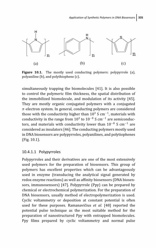
March 14, 2012 18:19 PSP Book - 9in x 6in 10-Ozsoz-c10
Application of Synthetic Polymers in DNA Biosensors 335
(a) (b) (c)
Figure 10.1. The mostly used conducting polymers: polypyrrole (a),
polyaniline (b), and polythiophene (c).
simultaneously trapping the biomolecules [41]. It is also possible
to control the polymeric film thickness, the spatial distribution of
the immobilized biomolecule, and modulation of its activity [45].
They are mostly organic conjugated polymers with a conjugated
π -electron system. In general, conducting polymers are considered
those with the conductivity higher than 103 S cm−1, materials with
conductivity in the range from 103 to 10−8 S cm−1 are semiconduc-
tors, and materials with conductivity lower than 10−8 S cm−1 are
considered as insulators [46]. The conducting polymers mostly used
in DNA biosensors are polypyrroles, polyanilines, and polytiophenes
(Fig. 10.1).
10.4.1.1 Polypyrroles
Polypyrroles and their derivatives are one of the most extensively
used polymers for the preparation of biosensors. This group of
polymers has excellent properties which can be advantageously
used in enzyme (transducing the analytical signal generated by
redox enzyme reactions) as well as affinity biosensors (DNA biosen-
sors, immunosensors) [47]. Polypyrrole (Ppy) can be prepared by
chemical or electrochemical polymerization. For the preparation of
DNA biosensors, usually method of electropolymerization is used.
Cyclic voltammetry or deposition at constant potential is often
used for these purposes. Ramanavicius et al. [48] reported the
potential pulse technique as the most suitable method for the
preparation of nanostructured Ppy with entrapped biomolecules.
Ppy films prepared by cyclic voltammetry and normal pulse
March 14, 2012 18:19 PSP Book - 9in x 6in 10-Ozsoz-c10
336 Synthetic Polymers for Electrochemical DNA Biosensors
voltammetry (NPV) in order to prepare electrochemical DNA biosen-
sors were compared [49]. The NPV method enabled to prepare Ppy
nanofiber films with higher electroactivity due to higher specific
surface area. The potentiostatic and potentiodynamic method of
electropolymerization was used to prepare Ppy nanofibers [50].
Electrodes prepared by the potentiostatic procedure showed higher
responses to the oxidation of dsDNA than the electrodes prepared
by potentiodynamic methods.
Ppy can be electropolymerized from both aqueous and nonaque-
ous solvents [12]. For DNA biosensors the biocompatability of Ppy is
important as well as the fact that it can also be electropolymerized
from neutral aqueous solutions. Different conditions affecting DNA
adsorption onto conducting Ppy, including pH, buffer nature, ionic
strength, and substrate, were studied [22]. Maximum amount of
DNA was adsorbed from a solution of pH 5.1 because of the
high density of positive charge of Ppy, and also positive effect
of ionic strength was reported. DNA adsorbed at the Ppy surface
decreases the ionic conductivity of the polymer, but on the other
hand maintains the mobility of the dopant anions within the bulk
Ppy [23]. Anions incorporated as dopants into the Ppy during the
process of electropolymerization have a positive effect on polymer
stability [12]. Anions from the supporting electrolyte incorporated
into the polymer achieve its electroneutrality. However, other
anions can also be used as counterions. Large polymeric anions,
such as polyvinyl sulfonate, were used as counterions in the
preparation of DNA biosensors [40, 51]. Such doped Ppy can
displace negative PVS with PO−4 of DNA [24]. It was found
that the adsorption of DNA onto electropolymerized Ppy–PVS
reached the maximum at pH 6.0, and FTIR studies showed the
electrostatic interaction between the DNA and polymeric film. A
Ppy–PVS film was prepared at the surface of ITO electrodes by
chronopotentiometrical electropolymerization from the solution
containing pyrrole and PVS [51]. DNA was then physisorbed onto
the polymer, and the resulting biosensor had improved sensitivity
to 3-chlorophenol (0.1–25 ppm) and 2-aminoanthracene (0.01–15
ppm). The response time was about 30 seconds. Incorporation
of the DNA into the polymeric layer during electropolymerization
led to increased sensitivity to both 3-chlorophenol (0.01–55 ppm)
March 14, 2012 18:19 PSP Book - 9in x 6in 10-Ozsoz-c10
Application of Synthetic Polymers in DNA Biosensors 337
and 2-aminoanthracene (0.001–6 ppm) [52]. A similar DNA biosen-
sor was also used for the detection of organophosphates such
as chlorpyrifos and malathion up to 0.0016 ppm and 0.17 ppm,
respectively [53].
Because of the negative charge, ODN can also serve as a dopant of
Ppy. A Ppy–ODN film was prepared at the surface of gold electrode
for genoelectronic application [54]. It was found that the redox
activity of the biosensor was affected by presence of ODN molecules
and it was able to discriminate between synthetic oligonucleotides
and chromosomal DNA. Komarova et al. [55] prepared the DNA
biosensor at the surface of ITO electrodes electrochemically from the
solution containing Py and ODN. ODN served as a sole dopant, and
a prepared biosensor was used for chronoamperometric detection
of the target ODN with the detection limit of 1.6 fmol in 0.1
ml. An ssDNA/polypyrrole-modified electrode for the detection
of specific bovine leukemia virus provirus DNA sequences was
prepared [56]. In this case, Ppy was electrochemically doped with
ssDNA in the presence of KCl, which eliminated a nonspecific
contribution. A Ppy film doped with oligonucleotide probe was
also formed at the surface of microelectrodes in the presence
of LiClO4 in order to prepare an impedance DNA hybridization
biosensor [57]. The biosensor was applied for the detection of
nanomolar concentrations of target ODN at the silicon array chip
containing four gold microelectrodes. The Ppy–ODN film was
also electropolymerized at the surface of Au electrode from the
solution containing pyrrole, ODN, and NaCl by continuous cyclic
voltammetry [43, 58]. An electrode was used for the detection of
DNA hybridization. A thin film of Ppy doped with an ODN probe was
electropolymerized at the surface of gold microelectrodes integrated
on the chip and used for sensing electrical potential-assisted DNA
hybridization and pathogen target DNA detection [59]. Detection of
0.34 pmol and 0.072 fmol of complementary ODN target in 0.1 mL
within a time of seconds were achieved on unpolished and polished
electrodes, respectively.
Another approach was described by Livache et al. [60]. Pyrrole
was first functionalized by ODN using pyrrole–phosphoramidite
building blocks. Next, Ppy copolymer was prepared by electropoly-
merization in the solution containing pyrrole and pyrrole–ODN. This
March 14, 2012 18:19 PSP Book - 9in x 6in 10-Ozsoz-c10
338 Synthetic Polymers for Electrochemical DNA Biosensors
procedure led to the synthesis of a Ppy film bearing covalently
linked ODN. The hybridization event was detected using a quartz
crystal microbalance method (QCM) [60–63]. This method was also
applied to prepare silicon DNA chip containing 48 or 128 gold
microelectrodes, where the hybridization reaction was evaluated
using fluorescence [60, 62, 64, 65]. A similar procedure was
described for the preparation of biotinylated Ppy film at the
surface of gold quartz crystals as well as silicon chip containing
48 gold microelectrodes [66–68], where biotin was used for the
immobilization of avidin. Then biotinylated ODN was immobilized
via the biotin/avidin affinity bond.
Polypyrrole can also be functionalized with the electrochemical
indicator of DNA, such as ferrocenyl groups bearing an active ester
group used for the covalent binding of amino-labeled ODN probe
[69]. Hybridization with complementary ODN caused a decrease in
the current density and a shift of the oxidation wave of the ferrocenyl
group because of the decrease of polymer permeability. This was
explained by the change of the conformation along the conjugated
backbone of the polymer. The prepared DNA biosensor was able to
detect less than 1 pmol of target ODN.
The gold electrode was modified with a copolymer using
the monomers 3-acetic acid pyrrole and 3-N -hydroxyphthalimide
pyrrole [36, 70]. This copolymer contained activated ester groups
used for covalent grafting of an ssDNA probe bearing a terminal
amino group. It was found that porous Ppy led to a higher density
of immobilized DNA probes and improved the detection of the
hybridization reaction. The same copolymer was used for the
preparation of a multiplot DNA biosensor based on microelec-
trodes deposited on the chip [71]. The polymer offered direct
transduction of the recognition process into an electrochemical
signal because its signature varied according to a hybridization
event. Another copolymer-based DNA biosensor was prepared
by electropolymerization of Py in the presence of 4-(-3-pyrrolyl)
butanoic acid [29]. Ppy was also used as an electrostatic adsorption
matrix, which allowed immobilization of DNA onto the porous
silicon substrate without using covalent bonds [72]. Polypyrroles
are reported as a convenient matrix for the immobilization of
nanomaterials at the surface of an electrode [73]. In this case the
March 14, 2012 18:19 PSP Book - 9in x 6in 10-Ozsoz-c10
Application of Synthetic Polymers in DNA Biosensors 339
combination of the unique properties of conducting polymers and
those of nanomaterials exhibits a synergic effect, which positively
affects the stability, electron transfer, and performance of the
final biosensors. The Ppy film possessed the uniform surface
for the immobilization of Au–Pt hybrid nanoparticles [74]. Ppy
was also prepared by electropolymerization in the presence of
multiwalled carbon nanotubes (MWCNTs) ended with carboxylic
groups [75]. MWCNTs served as the nano-sized backbone for Ppy
polymerization, which allowed the formation of porous Ppy film
covered around the MWCNTs in a cylindrical structure and offered
stable surface for DNA immobilization. The activity of MWCNT
surface can lower the nucleation energy required for the beginning
of electropolymerization of the Ppy/DNA film [41]. Therefore, the
growth of the polymer film occurred at potential +0.4 V vs. Ag/AgCl
in contrast to +0.6 V observed at bare GCE. The high surface area
of MWCNTs also allowed the deposition of greater volume of the
polymer without increasing the thickness of the film.
10.4.1.2 Polyaniline
Polyaniline is widely used for the preparation of the electrochemical
enzyme biosensors and immunosensors [76]. However, several
applications in DNA biosensors can also be found. PANI can be pre-
pared by electropolymerization using the galvanostatic method or
the potentiostatic method, leading to a polymer adhered weakly at
the electrode surface or potential cycling, which produces polymer
well adhered at the electrode surface [77]. The electropolymerizaton
of PANI is usually provided from acidic media [78]. The properties
of the PANI synthesized from different acids were investigated
[79]. The authors showed that polymer synthesized with perchloric
acid had the highest conductivity in neutral solutions (pH of 6.6),
which is environmentally convenient for biomolecules. Abdullin
et al. [80] studied the redox properties of the DNA–polyaniline film
over a wide range of pH. Authors found that the well-reproducible
and reversible voltammetric signals of the DNA–PANI film were
observed at physiological pH values. Screen-printed carbon elec-
trodes modified with electropolymerized PANI, electropolymerized
polydiaminobenzene (PDAB), and polyethyleneimine (PEI) were
March 14, 2012 18:19 PSP Book - 9in x 6in 10-Ozsoz-c10
340 Synthetic Polymers for Electrochemical DNA Biosensors
compared in order to prepare ssDNA biosensors for detection of the
hybridization event [81]. The best results were obtained using PANI
and PEI-modified DNA biosensors. PDAB-modified DNA biosensors
showed some unselective binding. Moreover, PANI allowed finer
control and monitoring of the deposition process. Similarly to Ppy,
PANI can also be doped by anionic dopants, which improve the
conductivity and stability of the resulting polymer. PANI fibers were
used as electrodes to study the influence of electrolyte counterions
and pH on the electrochemical behavior of PANI fibers [82]. The
highest currents were observed in a solution of HCl and HNO3, and
the authors concluded that the size of counterions is less important
than the anion charge. Moreover, only fully protonated PANI fibers
showed the same electrochemical properties as the PANI film. DNA
was covalently attached onto PANI nanotubes synthesized on the
graphite electrode [83]. The collective effect of PANI nanotubes as
well as enhanced conductivity led to an extremely high sensitivity
and fast hybridization kinetics. Biotinylated ODN specific to E.coli was immobilized onto an avidin–PANI-modified Pt electrode
[84]. The bioelectrode enabled faster, ultrasensitive, and direct
reagentless detection of E. coli. A PANI–PVS film was prepared at
the surface of the ITO electrode by electropolymerization of aniline
in the presence of PVS, LiClO4, and DNA [85]. The increase in the
conductivity with the increased concentration of PVS was attributed
to an acidic microenvironment for PANI formation. The DNA
biosensor was prepared using the copolymer of PANI and chitosan
[86]. The biosensor showed enhanced electron-transfer properties
toward [Fe(CN)6]3−/4−, which was attributed to the combination
of the excellent conductivity of PANI and the cationic character of
chitosan. PANI nanowires were synthesized electrochemically on the
surface of GCE [87]. Then phosphate-ended ODNs were covalently
attached onto the amino groups of PANI nanowires. The biosensor
effectively discriminated complementary and noncomplementary
DNA sequences. The positive effect of nanomaterials on the PANI
properties was reported. Due to the synergistic effect of MWCNTs
and PANI, a high amount of the DNA probe was immobilized on the
surface of the electrode [88]. Enhanced stability of the PANI film was
observed when it was electropolymerized in the presence of ssDNA-
wrapped single-walled carbon nanotubes (ssDNA-SWCNTs) [89].
March 14, 2012 18:19 PSP Book - 9in x 6in 10-Ozsoz-c10
Application of Synthetic Polymers in DNA Biosensors 341
ssDNA-SWCNTs served as conductive polyanionic doping agents
and, therefore, enhanced the conductivity and redox activity of the
resulting film.
10.4.1.3 Polythiophene and its derivatives
Polythiophenes and their derivatives are also widely used for the
preparation of DNA biosensors. The disadvantage of these polymers
is difficult electropolymerization of polymers with functional groups
suitable for the immobilization of biomolecules (amino or carboxylic
groups) [90]. Another reported disadvantage is very positive
oxidation potential of monomers [91]. Electropolymerization by
several cycles between 0.0 and +1.1 V was used for the preparation
of terthiophene with an activated ester-terminated side chain [92].
Then the polymer-bearing electrode was incubated in a solution
of aminoalkyl-terminated ODNs. After immobilization of the ODNs,
the authors observed a decrease in the oxidation current as well
as a slight shift of the peak potential. The authors concluded that
immobilized ODNs could cause distortion of the polythiophene
polymer and loss of conjugation. A modified electrode was used
for detecting the presence of mRNA in biological samples. A
poly(cyclopentadithiophene) matrix was tested for electrochemi-
cally controlled DNA delivery [93]. DNA was covalently immobilized
at the surface of the polymer-modified electrode. Quartz crystal
microbalance was used to detect the amount of delivered DNA. The
redox and ion exchange properties of poly(cyclopentadithiophene)
matrix covalently modified with ODNs were investigated using
electrochemical impedance spectroscopy [94]. It was shown that
the ODNs immobilized at the surface of a quartz crystal caused the
blocking of the surface. After hybridization with long target ODNs
a Warburg behavior was restored. DNA was employed as dopant of
PEDOT [95]. Electropolymerized poly(4-hydroxyphenyl thiophene-
3-carboxylate) as cationic polymer was advantageously used for
the electrostatic binding of polyanionic ODNs [96]. Moreover,
interaction between PEDOT and specific ODNs was studied using
electophoresis and spectroscopic methods [97]. It was shown
that together with nonspecific electrostatic interactions, specific
hydrogen binding interactions between polymer and methylated

March 14, 2012 18:19 PSP Book - 9in x 6in 10-Ozsoz-c10
342 Synthetic Polymers for Electrochemical DNA Biosensors
ODNs appeared, and stable complexes were formed. PEDOT was first
prepared by electropolymerization at the surface of GCE, and then
a DNA solution was spread over the polymer-modified electrode
[98]. DNA was available for the electrostatic binding of Nile blue
as redox indicator. The composite electrode showed electrocatalytic
properties toward the reduction of hydrogen peroxide.
10.4.2 Redox Polymers
Redox-active polymers are conducting polymers containing specific
electrostatically isolated but electrochemically active sites which
can be oxidized or reduced [99]. Redox centers are either organic
molecules or redox-active transition metals covalently bound to
polymer backbone.
10.4.2.1 Quinone-containing polymers
Quinone-containing polymers, namely poly(5-hydroxy-1,4-naphtho-
quinone-co-5-hydroxy-3-thioacetic acid-1,4-naphthoqinone), also
known as poly(JUG-co-JUGA), are also popular for the preparation
of DNA biosensors. In contrast to classical conducting polymers,
such as Ppy or PANI where signal transduction is performed via
redox process of the polymer exchanging anion, in the case of
poly(JUG-co-JUGA) the signal is transduced by the quinone group
in the polymer [33]. The carboxylic group in such copolymers
allows the binding of amino-terminated ODNs, and it shows a very
stable electroactivity in neutral aqueous solutions and can also
work as a hybridization indicator [100]. The copolymer poly(JUG-
co-JUGA) was used for the preparation of DNA biosensors. ODN
was immobilized covalently onto polymeric film from a solution
containing ODN, EDC, and NHS [33–35]. It was shown that, due
to the redox characteristics of the quinone group, the poly(JUG-
co-JUGA) film can be used as an enhanced transducer in ODN
hybridization detection. Interaction and steric effects between DNA
and poly(JUG-co-JUGA) were studied [101]. The authors observed
that only a very short DNA was adsorbed onto the polymeric film
and that the surface concentration of hybrids depended on the
target length. Poly(JUG-co-JUGA)-modified electrodes were tested as
label-free DNA hybridization electrochemical sensors, which used
March 14, 2012 18:19 PSP Book - 9in x 6in 10-Ozsoz-c10
Application of Synthetic Polymers in DNA Biosensors 343
the electrochemical activity of quinone in the polymer for the
detection of the hybridization event [34, 102]. By the electropoly-
merization of poly(JUG-co-JUGA) onto an MWNT-modified electrode
in nonaqueous media, an interpenetrated conductive network
electroactive in both aqueous and nonaqueous media was produced
[103]. An electropolymerized polyquinone film was derivatized
with glutathione [104]. Glutathione was used as a precursor
for subsequent biomolecule linkage via carboxylic groups. Free
carboxylic groups were first transformed into ester groups using
EDC, and then amino-terminated DNA was immobilized. Because
the polymeric film is a cation exchanger, the negatively charged
DNA cannot be nonspecifically adsorbed at the surface. A solution
of poly(1,4-benzoquinone) prepared by enzymatic synthesis was
cast at the surface of carbon fiber electrodes, and then DNA was
immobilized [105]. The polymer film allowed the hybridization
detection by scanning electrochemical microscopy in the positive-
feedback mode.
10.4.2.2 Redox-active polymers containing organometalicredox center
Redox-active polymers containing ferrocene as redox center were
employed in DNA biosensors. Poly(vinylferrocene) is a soluble
polymer which can be easily deposited at the surface of Pt [106,
107] or graphite working electrode [108] by its electrooxidation
resulting in a less soluble polymer, poly(vinylferrocenium). Such an
electrode can then be advantageously used for the immobilization of
negatively charged DNA. Low nonspecific immobilization of DNA on
this polymer was reported [108]. The electrochemical signal of such
polymer can be used for the detection of the hybridization event
[107]. Another approach was used by Cui et al. [109]. First GCE was
modified with DNA. After drying, the layer of poly(ferrocenylsilane)
was cast at DNA/GCE. It was shown that the DNA at the surface of
GCE enhanced the adsorption of the polymer as well as the electron-
transfer properties. Therefore, the prepared biosensor showed good
electrocatalytic activity toward oxidation of ascorbic acid.
Osmium bipyridyl complexes are known to catalyze the elec-
trooxidation of the guanine base in DNA and also enhance the
March 14, 2012 18:19 PSP Book - 9in x 6in 10-Ozsoz-c10
344 Synthetic Polymers for Electrochemical DNA Biosensors
detection of DNA [110]. It is convenient to immobilize these
complexes at the electrode surface using a polymer matrix. DNA
can be immobilized either with polymer [111] or redox polymer
electrodeposited onto a DNA layer [112, 113]. Such a polymer forms
a stable and reproducible surface and works as an electron-transfer
mediator.
10.4.3 Nonconducting Polymers
Nonconducting polymers are not so frequently used in DNA
biosensors as conducting ones. They have high resistivity, but
their permselectivity is very useful in preventing interferences
in electrochemical biosensors [114]. In this group of polymers,
polyethyleneimine (PEI) and chitosan (CHIT) are very often used for
the preparation of DNA biosensors.
CHIT is a pseudonatural polymer formed from chitin when
the degree of its deacetylation reaches 50% [115]. Both PEI and
CHIT are cationic polymers with good biocompatibility and high
positive charge density, which allows for easy electrostatic DNA
immobilization. Study of interaction between the DNA molecule and
PEI–copper(II) complexes showed that together with electrostatic
interaction, van der Waals interactions and hydrogen binding are
also employed probably due to the presence of multiple copper(II)
complex molecular units and free amine groups of the polymer
[116, 117]. Electron-transfer kinetics at the PEI–DNA-modified
electrode was studied [118]. It was shown that the surface of
modified electrodes was homogeneous and electron transfer was
slower when PEI formed an external layer. Moreover, further
modification with PEI–gold nanoparticles enhanced the electron
transfer. PEI was used to disperse the MWCNTs, and the screen-
printed electrode (SPCE) was modified with the resulting composite
[119]. MWCNT–PEI formed a layer suitable for the electrostatic
adsorption of negatively charged DNA. DNA/MWCNT–PEI/SPCE was
used for the detection of DNA damage by quinazolines. Interaction
of PEI and CHIT with plasmid DNA (pDNA) on a hanging mercury
drop electrode was compared [120]. Voltammetric studies showed
that each polymer interacts with pDNA by different mechanisms
and that a higher amount of PEI interacts with pDNA than was
March 14, 2012 18:19 PSP Book - 9in x 6in 10-Ozsoz-c10
Application of Synthetic Polymers in DNA Biosensors 345
observed in the case of CHIT. However, DNA and CHIT can form
stable complexes of specific sizes, influenced by the molecular
weight and pH of CHIT [121]. An assembled film composed of DNA
and CHIT was prepared using the layer-by-layer technique at the
surface of the pyrolytic graphite electrode [122]. CHIT enabled the
effective intercalation of 9,10-anthraquinone-2,6-disulfonate into
the double helix of DNA. A biosensor was successfully applied for
the detection of DNA damage caused by the Fenton reagent. Cu(II)
ions were successfully immobilized in the DNA/CHIT layer due to
the formation of Cu(II)–DNA complexes [123]. This amperometric
biosensor showed excellent electroactivity toward hydrogen per-
oxide with the detection limit of 3 μmol/l. CHIT was also used
to disperse MWCNTs [124–126]. CHIT as GCE modifier partially
blocked the electrochemical response of electroactive species [124].
Introduction of MWCNTs enhanced the electron-transfer properties
of the electrode surface, although values obtained at the bare GCE
were still better. It was shown that CHIT strongly enhanced the
homogeneity of MWCNT deposition onto the electrode surface in
comparison to dispersion in dimethylformamide and MWCNT–CHIT
formed a suitable interface for the immobilization of the DNA
layer in order to study the DNA damage [125]. Electrochemical
properties of screen-printed electrodes modified with composites
of SWCNT–CHIT, MWCNT–CHIT, and (SWCNT-COOH)–CHIT were
studied [127]. It was shown that CHIT alone was able to decrease the
charge-transfer resistance (RCT) of the electrode surface. However,
the decrease in RCT was much more significant when the carbon
nanotube–CHIT composite was used as an electrode modifier. The
best results were obtained in the case of (SWCNT-COOH)–CHIT
because of electrostatic interaction of the negative charge of the
carboxylic group of SWCNTs and the positive charge of CHIT.
Moreover, the (SWCNT-COOH)–CHIT composite was shown as the
best environment for DNA immobilization and was successfully used
for the study of DNA damage caused by lipid peroxidation products.
Overoxidized Ppy(Ppyox) is another example of nonconducting
polymers. It is known that Ppy irreversibly loses electroactivity at
potentials more positive than +1.0 V vs. Ag/AgCl yielding into the
formation of an insulating layer with the porous structure [128]
and the nanoporous diffusion activity [28], both convenient for DNA
March 14, 2012 18:19 PSP Book - 9in x 6in 10-Ozsoz-c10
346 Synthetic Polymers for Electrochemical DNA Biosensors
immobilization [129]. The Ppy layer was overoxidized potentiosta-
tically at the potential of +1.8 V vs. Ag/AgCl. The prepared DNA–
Ppyox-modified carbon fiber electrode showed excellent sensitivity
and selectivity toward neurotransmitters. In order to increase the
permeability of the Ppy film, an electrochemical overoxidation was
also performed by cycling the potential between 0.0 and 1.3 V vs.
Ag/AgCl until the reversible peak, indicating the Ppy conductivity
disappeared [130, 131].
10.5 Conclusions
Today, there is an increasing interest in the construction and
utilization of DNA biosensors. Successful DNA immobilization plays
a key role in the final efficiency of biosensors. Using polymers
seems to be an elegant way for immobilization of biomolecules.
Moreover, conducting as well as nonconducting polymers not
only represent a matrix suitable for DNA immobilization but also
increase the sensitivity and selectivity of the final biosensor by
avoiding interferences and enhance the stability of the modifier
layer. The thickness of the electropolymerized polymers can be
easily controlled selecting the electropolymerization conditions, and
redox properties can be modified by choosing a suitable dopant
molecule. In recent years, various nanomaterials have been used in
the construction of DNA biosensors. They are usually insoluble in
most solvents, but they can be advantageously entrapped within the
polymer at the electrode surface. Moreover, composites of polymers
and nanomaterials offer a range of new properties, such as enhanced
electron transfer, biocompatibility, and small dimensions with large
surface area, attractive for the miniaturization of DNA biosensors.
List of abbreviations
CHIT chitosan
CP conducting polymer
DNA deoxyribonucleic acid
March 14, 2012 18:19 PSP Book - 9in x 6in 10-Ozsoz-c10
References 347
EDC 1-ethyl-3-(3-dimethylaminopropyl)carbodiimide
GCE glassy carbon electrode
ITO indium tin oxide
MWCNT multiwalled carbon nanotube
NHS N -hydroxysuccinimide
NPV normal pulse voltammetry
ODN oligodeoxyribonucleotide
PANI polyaniline
PDAB polydiaminobenzene
PEDOT poly(3,4-ethylenedioxythiophene)
PEI polyethyleneimine
Ppy polypyrrole
PSS poly(styrene sulfonic acid)
PVS polyvinylsulfonate
QCM quartz crystal microbalance
SPCE screen-printed carbon electrode
SWCNT single-walled carbon nanotube
References
1. M. Ates and A. S. Sarac, Prog. Org. Coat. 66, 337–358 (2009).
2. M. E.Tess and J. A. Cox, J. Pharm. Biomed. Anal. 19, 55–68 (1999).
3. Z. Chang, H. Fan, K. Zhao, M. Chen, P. He, and Y. Fang, Electroanalysis 20,
131–136 (2008).
4. G. A. Rivas, M. D. Rubianes, M. C. Rodrıguez, N. F. Ferreyra, G. L. Luque,
M. L. Pedano, S. A. Miscoria, and C. Parrado, Talanta 74, 291–307
(2007).
5. H. Xu, H. Wu, C. Fan, W. Li, Z. Zhang, and L. He, Chin. Sci. Bull. 49, 2227–
2231 (2004).
6. K. M. Manesh, P. Santhosh, A. Gopalan, and K. P. Lee, Talanta 75, 1307–
1314 (2008).
7. P. Cooreman, R. Thoelen, J. Manca, M. vandeVen, V. Vermeeren,
L. Michiels, M. Ameloot, and P. Wagner, Biosens. Bioelectron. 20, 2151–
2156 (2005).
8. J. C. Vidal, E. Garcia-Ruiz, and J. R. Castillo, Microchim. Acta 143, 93–111
(2003).
March 14, 2012 18:19 PSP Book - 9in x 6in 10-Ozsoz-c10
348 Synthetic Polymers for Electrochemical DNA Biosensors
9. M. V. Deshpande and D. P. Amalnerkar, Prog. Polym. Sci. 18, 623–649
(1993).
10. C. Mousty, B. Galland, and S. Cosnier, Electroanalysis 13, 186–190
(2001).
11. P. Gros, H. Durliat, and M. Comtat, Electrochim. Acta 46, 643–650
(2000).
12. R. Ansari, E-J. Chem. 3, 186–201 (2006).
13. J. B. Raoof, R. Ojani, and S. Rashid-Nadimi, Electrochim. Acta 49, 271–
280 (2004).
14. S. Cosnier, Appl. Biochem. Biotechnol. 89, 127–138 (2000).
15. J. M. Goddard and J. H. Hotchkiss, Prog. Polym. Sci. 32, 698–725 (2007).
16. T. Ahuja, I. A. Mir, D. Kumar, and Rajesh, Biomaterials 28, 791–805
(2007).
17. S. Cosnier, Biosens. Bioelectron. 14, 443–456 (1999).
18. F. R. R. Teles and L. P. Fonseca, Mater. Sci. Eng. C 28, 1530–1543 (2008).
19. J. Li, Q. Liu, Y. Liu, S. Liu, and S. Yao, Anal. Biochem. 346, 107–114
(2005).
20. Y. Zhang, K. Zhang, and H. Ma, Anal. Biochem. 387, 13–19 (2009).
21. J. Galandova and J. Labuda, Chem. Papers 63, 1–14 (2009).
22. B. Saoudi, N. Jammul, M. L. Abel, M. M. Chehimi, and G. Dodin, SyntheticMet. 87, 97–103 (1997).
23. B. Saoudi, C. Despas, M. M. Chehimi, N. Jammul, M. Delamar, J. Bessiere,
and A. Walcarius, Sensor Actuat. Chem. B 62, 35–42 (2000).
24. A. Gambhir, M. Gerard, S. K. Jain, and B. D. Malhotra, Appl. Biochem.Biotechnol. 96, 313–319 (2001).
25. M. L. Pedano and G. A. Rivas, Biosens. Bioelectron. 18, 269–277 (2003).
26. M. Dıaz-Gonzalez, A. de la Escosura-Muniz, M. B. Gonzalez-Garcıa, and
A. Costa-Garcıa, Biosens. Bioelectron. 23, 1340–1346 (2008).
27. X. Lin, G. Kang, and L. Lu, Bioelectrochemistry 70, 235–244 (2007).
28. X. Jiang and X. Lin, Anal. Chim. Acta 537, 145–151 (2005).
29. H. Peng, C. Soeller, N. Vigar, P. A. Kilmartin, M. B. Cannell, G. A.
Bowmaker, R. P. Cooney, and J. Travas-Sejdic, Biosens. Bioelectron. 20,
1821–1828 (2005).
30. H. Peng, L. Zhang, J. Spires, C. Soeller, and J. Travas-Sejdic, Polymer 48,
3413–3419 (2007).
31. H. Peng, C. Soeller, N. A. Vigar, V. Caprio, and J. Travas-Sejdic, Biosens.Bioelectron. 22, 1868–1873 (2007).
March 14, 2012 18:19 PSP Book - 9in x 6in 10-Ozsoz-c10
References 349
32. X. Li, J. Xia, and S. Zhang, Anal. Chim. Acta 622, 104–110 (2008).
33. S. Reisberg, B. Piro, V. Noel, and M. C. Pham, Bioelectrochemistry 69,
172–179 (2006).
34. S. Reisberg, L. A. Dang, Q. A. Nguyen, B. Piro, V. Noel, P. E. Nielsen, L. A.
Le, and M. C. Pham, Talanta 76, 206–210 (2008).
35. B. Piro, J. Haccoun, M. C. Pham, L. D. Tran, A. Rubin, H. Perrot, and
C. Gabrielli, J. Electroanal. Chem. 577, 155–165 (2005).
36. C. Tlili, H. Korri-Youssoufi, L. Ponsonnet, C. Martelet, and N. J. Jaffrezic-
Renault, Talanta 68, 131–137 (2005).
37. N. Prabhakar, H. Singh, and B. D. Malhotra, Electrochem. Commun. 10,
821–826 (2008).
38. P. de-los-Santos-Alvarez, M. J. Lobo-Castanon, A. J. Miranda-Ordieres,
and P. Tunon-Blanco, Anal. Bioanal. Chem. 378, 104–118 (2004).
39. K. Arora, N. Prabhakar, S. Chand, and B. D. Malhotra, Biosens.Bioelectron. 23, 613–620 (2007).
40. K. Arora, N. Prabhakar, S. Chand, and B. D. Malhotra, Sensor Actuat.Chem. B 126, 655–663 (2007).
41. Y. Xu, Y. Jiang, H. Cai, P. G. He, and Y. Z. Fang, Anal. Chim. Acta 516, 19–27
(2004).
42. J. Wang, M. Jiang, A. Fortes, and B. Mukherjee, Anal. Chim. Acta 402,
7–12 (1999).
43. H. Peng, C. Soeller, M. B. Cannell, G. A. Bowmaker, R. P. Cooney, and
J. Travas-Sejdic, Biosens. Bioelectron. 21, 1727–1736 (2006).
44. L. Zhai and R. D. McCullough, J. Mater. Chem. 14, 141–143 (2004).
45. B. A. Gregg and A. Heller, Anal. Chem. 62, 258–263 (1990).
46. N. K. Guimard, N. Gomez, and C. E. Schmidt, Prog. Polym. Sci. 32, 876–
921 (2007).
47. B. D. Malhotra, A. Chaubey, and S. P. Singh, Anal. Chim. Acta 578, 59–74
(2006).
48. A. Ramanavicius, A. Ramanaviciene, and A. Malinauskas, Electrochim.Acta 51, 6025–6037 (2006).
49. Kh. Ghanbari, S. Z. Bathaie, and M. F. Mousavi, Biosens. Bioelectron. 23,
1825–1831 (2008).
50. A. Ozcan, Y. Sahin, M. Ozsoz, and S. Turan, Electroanalysis 19, 2208–
2216 (2007).
51. K. Arora, A. Chaubey, R. Singhal, R. P. Singh, M. K. Pandey, S. B. Samanta,
B. D. Malhotra, and S. Chand, Biosens. Bioelectron. 21, 1777–1783
(2006).
March 14, 2012 18:19 PSP Book - 9in x 6in 10-Ozsoz-c10
350 Synthetic Polymers for Electrochemical DNA Biosensors
52. N. Prabhakar, K. Arora, S. P. Singh, H. Singh, and B. D. Malhotra, Anal.Biochem. 366, 71–79 (2007).
53. N. Prabhakar, K. Arora, S. P. Singh, M. K. Pandey, H. Singh, and B. D.
Malhotra, Anal. Chim. Acta 589, 6–13 (2007).
54. M. Jiang and J. Wang, J. Electroanal. Chem. 500, 584–589 (2001).
55. E. Komarova, M. Aldissi, and A. Bogomolova, Biosens. Bioelectron. 21,
182–189 (2005).
56. A. Ramanaviciene and A. Ramanavicius, Anal. Bioanal. Chem. 379, 287–
293 (2004).
57. C. M. Li, C. Q. Sun, S. Song, V. E. Choong, G. Maracas, and X. J. Zhang,
Front. Biosci. 10, 180–186 (2005).
58. J. Travas-Sejdic, H. Peng, R. P. Cooney, G. A. Bowmaker, M. B. Cannell,
and C. Soeller, Curr. Appl. Phys. 6, 562–566 (2006).
59. Y. Chen, Elling, Y. L. Lee, and S. C. Chong, J. Phys.: Conf. Ser. 34, 204–209
(2006).
60. T. Livache, E. Maillart, N. Lassalle, P. Mailley, B. Corso, P. Guedon,
A. Roget, and Y. Levy, J. Pharm. Biomed. Anal. 32, 687–696 (2003).
61. N. Lassalle, P. Mailley, E. Vieil, T. Livache, A. Roget, J. P. Correia, and L. M.
Abrantes, J. Electroanal. Chem. 509, 48–57 (2001).
62. N. Lassalle, A. Roget, T. Livache, P. Mailley, and E. Vieil, Talanta 55, 993–
1004 (2001).
63. K. Galasso, T. Livache, A. Roget, and E. Vieil, J. Chim. Phys. 95, 1514–
1517 (1998).
64. T. Livache, H. Bazin, P. Caillat, and A. Roget, Biosens. Bioelectron. 13,
629–634 (1998).
65. T. Livache, B. Fouque, A. Roget, J. Marchand, G. Bidan, R. Teoule, and
G. Mathis, Anal. Biochem. 255, 188–194 (1998).
66. A. Dupont-Filliard, A. Roget, T. Livache, and M. Billon, Anal. Chim. Acta449, 45–50 (2001).
67. A. Dupont-Filliard, M. Billon, T. Livache, and S. Guillerez, Anal. Chim.Acta 515, 271–277 (2004).
68. G. Bidan, M. Billon, K. Galasso, T. Livache, G. Mathis, A. Roget, L. M.
Torres-Rodriguez, and E. Vieil, Appl. Biochem. Biotechnol. 89, 183–193
(2000).
69. H. Korri-Youssoufi and B. Makrouf, Anal. Chim. Acta 469, 85–92 (2002).
70. C. Tlili, N. J. Jaffrezic-Renault, C. Martelet, and H. Korri-Youssoufi, Mater.Sci. Eng. C 28, 848–854 (2008).
March 14, 2012 18:19 PSP Book - 9in x 6in 10-Ozsoz-c10
References 351
71. F. Garnier, B. Bouabdallaoui, P. Srivastava, B. Mandrand, and C. Chaix,
Sens. Actuators, B-Chem. 123, 13–20 (2007).
72. J. H. Jin, E. C. Alocilja, and D. L. Grooms, J. Porous Mater. 17, 169–176
(2010).
73. I. Tiwari, K. P. Singh, and M. Singh, Russ. J. Gen. Chem. 79, 2685–2694
(2009).
74. X. Che, R. Yuan, Y. Chai, L. Ma, W. Li, and J. Li, Microchim. Acta 167, 159–
165 (2009).
75. Y. Xu, X. Ye, L. Yang, P. He, and Y. Fang, Electroanalysis 18, 1471–1478
(2006).
76. Di Wei and A. Ivaska, Chem. Anal. Warsaw, 51, 839–852 (2006).
77. S. Bhadra, D. Khastgir, N. K. Singha, and J. H. Lee, Prog. Polym. Sci. 34,
783–810 (2009).
78. J. Stejskal and R. Gilberg, Pure Appl. Chem. 74, 857–867 (2002).
79. Z. M. Tahir, E. C. Alocilja, and D. L. Grooms, Biosens. Bioelectron. 20,
1690–1695 (2005).
80. T. I. Abdullin, I. I. Nikitina, G. A. Evtugin, G. K. Budnikov, and L. Z.
Manapova, Russ. J. Electrochem. 43, 1284–1288 (2007).
81. F. Davis, A. V. Nabok, and S. P. J. Higson, Biosens. Bioelectron. 20, 1531–
1538 (2005).
82. R. Pauliukaite, C. M. A. Brett, and A. P. Monkman, Electrochim. Acta 50,
159–167 (2004).
83. H. Chang, Y. Yuan, N. Shi, and Y. Guan, Anal. Chem. 79, 5111–5115
(2007).
84. K. Arora, N. Prabhakar, S. Chand, and B. D. Malhotra, Anal. Chem. 79,
6152–6158 (2007).
85. N. Prabhakar, G. Sumana, K. Arora, H. Singh, and B. D. Malhotra,
Electrochim. Acta 53, 4344–4350 (2008).
86. A. Tiwari and S. Gong, Talanta 77, 1217–1222 (2009).
87. N. Zhu, Z. Chang, P. He, and Y. Fang, Electrochim. Acta 51, 3758–3762
(2006).
88. T. Yang, N. Zhou, Y. Zhang, W. Zhang, K. Jiao, and G. Li, Biosens.Bioelectron. 24, 2165–2170 (2009).
89. Y. Ma, S. R. Ali, A. S. Dodoo, and H. He, J. Phys. Chem. B 110, 16359–
16365 (2006).
90. H. Peng, L. Zhang, C. Soeller, and J. Travas-Sejdic, Biomaterials 30,
2132–2148 (2009).
March 14, 2012 18:19 PSP Book - 9in x 6in 10-Ozsoz-c10
352 Synthetic Polymers for Electrochemical DNA Biosensors
91. S. Scheib and P. Bauerle, J. Mater. Chem. 9, 2139–2150 (1999).
92. S. J. Higgins, F. Mouffouk, S. J. Brown, D. R. Williams, and A. R. Cossins,
Sens. Actuators, B-Chem. 122, 253–258 (2007).
93. C. Gautier, C. Cougnon, J. F. Pilard, N. Casse, and B. Chenais, Anal. Chem.
79, 7920–7923 (2007).
94. C. Cougnon, C. Gautier, J. F. Pilard, N. Casse, and B. Chenais, Biosens.Bioelectron. 23, 1171–1174 (2008.)
95. Y. Ner, M. A. Invernale, J. G. Grote, J. A. Stuart, and G. A. Sotzing, SyntheticMet. 160, 351–353 (2010).
96. A. Uygun, Talanta 79, 194–198 (2009).
97. C. Aleman, B. Teixeira-Dias, D. Zanuy, F. Estrany, E. Armelin, and L. J. del
Valle, Polymer 50, 1965–1974 (2009).
98. Z. Chen, A. Balamurugan, and S. Chen, Bioelectrochemistry 75, 13–18
(2009).
99. G. Inzelt, Conducting Polymers: A New Era in Electrochemistry, Springer
(2008).
100. M. C. Pham, B. Piro, L. D. Tran, T. Ledoan, and L. H. Dao, Anal. Chem. 75,
6748–6752 (2003).
101. B. Piro, S. Reisberg, V. Noel, and M. C. Pham, Biosens. Bioelectron. 22,
3126–3131 (2007).
102. S. Reisberg, B. Piro, V. Noel, T. D. Nguyen, P. E. Nielsen, and M. C. Pham,
Electrochim. Acta 54, 346–351 (2008).
103. D. F. Acevedo, S. Reisberg, B. Piro, D. O. Peralta, M. C. Miras, M. C. Pham,
and C. A. Barbero, Electrochim. Acta 53, 4001–4006 (2008).
104. S. Reisberg, D. C. Acevedo, A. Korovitch, B. Piro, V. Noel, I. Buchet, L. D.
Tran, C. A. Barbero, and M. C. Pham, Talanta 80, 1318–1325 (2010).
105. K. Nakano, K. Nakamura, K. Iwamoto, N. Soh, and T. Imato,
J. Electroanal. Chem. 628, 113–118 (2009).
106. F. Kuralay, A. Erdem, S. Abaci, H. Ozyoruk, and A. Yildiz, Electroanalysis20, 2563–2570 (2008).
107. F. Kuralay, A. Erdem, S. Abaci, H. Ozyoruk, and A. Yildiz, Anal. Chim. Acta643, 83–89 (2009).
108. F. Kuralay, A. Erdem, S. Abaci, H. Ozyoruk, and A. Yildiz, Electrochem.Commun. 11, 1242–1246 (2009).
109. K. Cui, Y. Song, and L. Wang, Electrochem. Commun. 10, 1712–1715
(2008).
110. P. A. Ropp and H. H. Thorp, Chem. Biol. 6, 599–605 (1999).

March 14, 2012 18:19 PSP Book - 9in x 6in 10-Ozsoz-c10
References 353
111. P. Kavanagh and D. Leech, Anal. Chem. 78, 2710–2716 (2006).
112. A. Liu, J. Anzai, and J. Wang, Bioelectrochemistry 67, 1–6 (2005).
113. L. Y. Zhang, Y. Wan, J. Zhang, D. Li, L. H. Wang, S. P. Song, and C. H. Fan,
Sci. China, Ser. B-Chem. 52, 746–750 (2009).
114. Y. Miao, J. Chen, and X. Wu, Trends Biotechnol. 22, 227–231 (2004).
115. M. Rinaudo, Prog. Polym. Sci. 31, 603–632 (2006).
116. R. S. Kumar and S. Arunachalam, Polyhedron 26, 3255–3262 (2007).
117. R. S. Kumar, K. Sasikala, and S. Arunachalam, J. Inorg. Biochem. 102,
234–241 (2008).
118. N. F. Ferreyra, S. Bollo, and G. A. Rivas, J. Electroanal. Chem. 638, 262–
268 (2009).
119. J. Galandova, R. Ovadekova, A. Ferancova, and J. Labuda, Anal. Bioanal.Chem. 394, 855–861 (2009).
120. I. Ch. Gherghi, S. Th. Girousi, M. Thanou, A. N. Voulgaropoulos, and
R. Tzimou-Tsitouridou, J. Pharm. Biomed. Anal. 39, 177–180 (2005).
121. M. Alatorre-Meda, P. Taboada, J. Sabın, B. Krajewska, L. M. Varela, and J.
R. Rodrıguez, Colloid Surface A 339, 145–152 (2009).
122. Y. Liu and N. Hu, Biosens. Bioelectron. 23, 661–667 (2007).
123. T. Gu, Y. Liu, J. Zhang, and Y. Hasebe, J. Environ. Sci. Suppl. 21, S56–S59
(2009).
124. S. Bollo, N. F. Ferreyra, and G. A. Rivas, Electroanalysis 19, 833–840
(2007).
125. J. Galandova, G. Ziyatdinova, and J. Labuda, Anal. Sci. 24, 711–716
(2008).
126. J. Galandova, L. Trnkova, R. Mikelova, and J. Labuda, Electroanalysis 21,
563–572 (2009).
127. A. Ferancova, K. Benıkova, J. Galandova, L. Sirotova, and J. Labuda, ActaChim. Slov. 1, 58–71 (2008).
128. S. Asavapiriyanont, G. K. Chandler, G. A. Gunawardena, and D. Pletcher,
J. Electroanal. Chem. 177, 229–244 (1984).
129. X. Jiang and X. Lin, Analyst 130, 391–396 (2005).
130. R. E. Ionescu, S. Herrmann, S. Cosnier, and R. S. Marks, Electrochem.Commun. 8, 1741–1748 (2006).
131. S. Cosnier, R. E. Ionescu, S. Herrmann, L. Bouffier, M. Demeunynck, and
R. S. Marks, Anal. Chem. 78, 7054–7057 (2006).

This page intentionally left blankThis page intentionally left blank

March 19, 2012 17:2 PSP Book - 9in x 6in 11-Ozsoz-c11
Chapter 11
Electrochemical Transducer forOligonucleotide Biosensor Basedon the Elimination and AdsorptiveTransfer Techniques
Libuse Trnkova,a Frantisek Jelen,b and Mehmet Ozsozc
aDepartment of Chemistry, Faculty of Science, Masaryk University,Kotlarska 2, CZ-611 37 Brno, Czech RepublicbInstitute of Biophysics, v.v.i., Academy of Sciences of the Czech Republic,Kralovopolska 135, CZ-612 65 Brno, Czech RepubliccAnalytical Chemistry Department, Faculty of Pharmacy,Ege University, 35100 Bornova, Izmir, [email protected]
11.1 Introduction
Electrochemical biosensors are usually based on redox reactions
that consume or produce electrons. Such a device can be re-
presented by an indication electrode, which integrates receptor–
transducer element providing selective quantitative analytical infor-
mation; recorded signals are proportional to analyte concentrations.
There are several types of electrochemical transducers, from which
Electrochemical DNA BiosensorsEdited by Mehmet OzsozCopyright c© 2012 Pan Stanford Publishing Pte. Ltd.ISBN 978-981-4241-77-9 (Hardcover), 978-981-4303-98-9 (eBook)www.panstanford.com

March 19, 2012 17:2 PSP Book - 9in x 6in 11-Ozsoz-c11
356 Electrochemical Transducer for Oligonucleotide Biosensor
amperometric transducers are most used in biosensors due to
their high sensitivity and selectivity. Except an indication electrode,
the electrochemical system contains other two electrodes, that
is, a reference electrode and an auxiliary electrode [1–4]. Our
approach in electrochemical oligonucleotide (ODN) transducer is
built on the adsorptive stripping voltammetric (AdSV) technique
in connection with elimination voltammetry with linear scan
(EVLS). Generally, EVLS enables the elimination of selected partial
voltammetric currents and the conservation of the other one
contributing to the increase of current sensitivity, the expansion of
electrode potential range (potential window) and the separation of
overlapped voltammetric signals. The basic idea of EVLS procedure
lies in the different dependencies of various voltammetric current
components on the scan rate. The elimination result can be achieved
by a function obtained by linear combination of total voltammetric
currents measured at different scan rates [5, 6].
11.2 Theoretical Fundamentals of EliminationVoltammetry with Linear Scan (EVLS)
11.2.1 Elimination Functions
Fourteen years ago, the theory of elimination voltammetry with
linear scan (EVLS) was published and experimentally verified for
selected electrode systems [5, 6]. To this date, the method has
been applied not only in electroanalytical chemistry, but also in the
study of electrode processes of inorganic and organic electroactive
substances at mercury, silver, or graphite electrodes [7–20]. EVLS
can be considered as a mathematical model of the transformation
of current–potential curves capable of eliminating certain selected
current components while securing the conservation of others by
means of elimination functions. For the calculation of the elimina-
tion functions, two or three voltammetric curves at different scan
rates should be recorded under identical experimental conditions.
It means that the linear sweep voltammetric (LSV) curves have to
be recorded with the same potential step, so that the I –E data sets
obtained for the same number of points on the potential axis, and

March 19, 2012 17:2 PSP Book - 9in x 6in 11-Ozsoz-c11
Theoretical Fundamentals of Elimination Voltammetry with Linear Scan (EVLS) 357
for the same potential range and the data are not influenced by the
current offset. One scan rate is taken as a reference, while more
scan rates are chosen as selected multiples of the reference scan
rate.
For elimination procedure, two necessary assumptions must be
fulfilled:
1. The total current resulting from different individual processes
such as diffusion, adsorption, and kinetics is formed by the sum
of these particular currents:
I = Id + Ic + Ik,
where Id, Ic, and Ik are the diffusion, charging, and kinetic
currents, respectively.
2. The particular currents eliminated are expressed as the product
of two independent functions:
I j = Y j (E )Wj (ν),
where Y j (E ) is the electrode potential function and Wj (ν) is the
scan rate function.
The scan rate function has the form of a certain power of x of the
scan rate. For example, for a substance transported to an electrode
only by diffusion, the rate power coefficient of 1/2 corresponds to
the diffusion current Id, while x = 1 or 0 holds for the charging
current Ic, or the kinetic current Ik, respectively [5–7, 21]. According
to the second condition of the elimination procedure, the particular
currents take the form
Id = Yd(E )v1/2, Ik = Yk(E )v0, and Ic = Yc(E )v1,
where Y j (E ) of the individual current characterizes a proportion-
ality which is independent of scan rate at the selected potential
value. It has been proved that for the elimination function f (I ) in
addition to the total current at a reference scan rate I , the total
currents for half and double of its value, I1/2 and I2, are suitable
[5, 7, 13, 21]. EVLS functions have been used for the different
combinations with the same scan rate ratio (integer 2) for more than
13 years. The types of six elimination functions are presented in
Table 11.1.
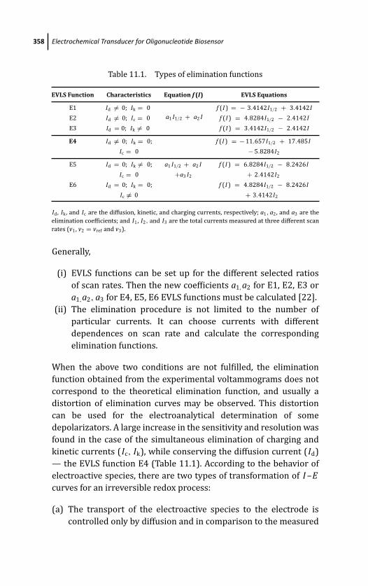
March 19, 2012 17:2 PSP Book - 9in x 6in 11-Ozsoz-c11
358 Electrochemical Transducer for Oligonucleotide Biosensor
Table 11.1. Types of elimination functions
EVLS Function Characteristics Equation f (I) EVLS Equations
E1 Id �= 0; Ik = 0
a1 I1/2 + a2 If (I ) = − 3.4142I1/2 + 3.4142I
E2 Id �= 0; Ic = 0 f (I ) = 4.8284I1/2 − 2.4142I
E3 Id = 0; Ik �= 0 f (I ) = 3.4142I1/2 − 2.4142I
E4 Id �= 0; Ik = 0; f (I ) = − 11.657I1/2 + 17.485I
Ic = 0 − 5.8284I2
E5 Id = 0; Ik �= 0; a1 I1/2 + a2 I f (I ) = 6.8284I1/2 − 8.2426I
Ic = 0 +a3 I2 + 2.4142I2
E6 Id = 0; Ik = 0; f (I ) = 4.8284I1/2 − 8.2426I
Ic �= 0 + 3.4142I2
Id, Ik, and Ic are the diffusion, kinetic, and charging currents, respectively; a1, a2, and a3 are the
elimination coefficients; and I1, I2, and I3 are the total currents measured at three different scan
rates (v1, v2 = vref and v3).
Generally,
(i) EVLS functions can be set up for the different selected ratios
of scan rates. Then the new coefficients a1,a2 for E1, E2, E3 or
a1,a2, a3 for E4, E5, E6 EVLS functions must be calculated [22].
(ii) The elimination procedure is not limited to the number of
particular currents. It can choose currents with different
dependences on scan rate and calculate the corresponding
elimination functions.
When the above two conditions are not fulfilled, the elimination
function obtained from the experimental voltammograms does not
correspond to the theoretical elimination function, and usually a
distortion of elimination curves may be observed. This distortion
can be used for the electroanalytical determination of some
depolarizators. A large increase in the sensitivity and resolution was
found in the case of the simultaneous elimination of charging and
kinetic currents (Ic, Ik), while conserving the diffusion current (Id)
— the EVLS function E4 (Table 11.1). According to the behavior of
electroactive species, there are two types of transformation of I –Ecurves for an irreversible redox process:
(a) The transport of the electroactive species to the electrode is
controlled only by diffusion and in comparison to the measured
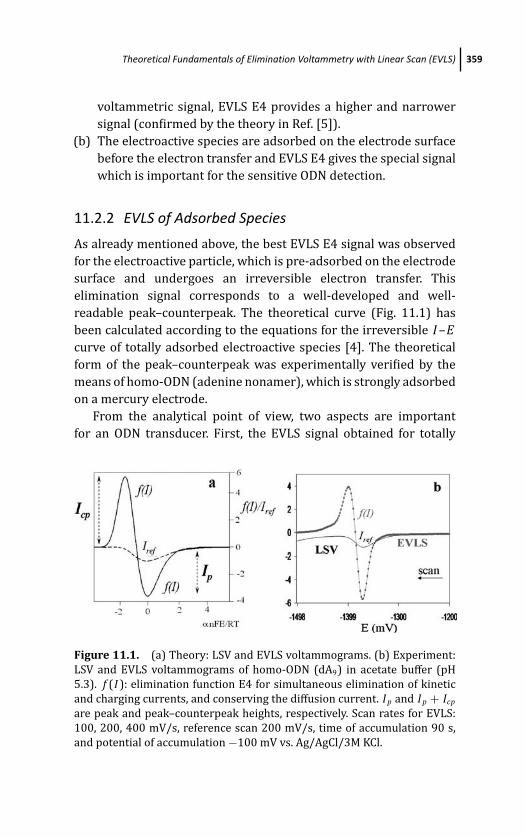
March 19, 2012 17:2 PSP Book - 9in x 6in 11-Ozsoz-c11
Theoretical Fundamentals of Elimination Voltammetry with Linear Scan (EVLS) 359
voltammetric signal, EVLS E4 provides a higher and narrower
signal (confirmed by the theory in Ref. [5]).
(b) The electroactive species are adsorbed on the electrode surface
before the electron transfer and EVLS E4 gives the special signal
which is important for the sensitive ODN detection.
11.2.2 EVLS of Adsorbed Species
As already mentioned above, the best EVLS E4 signal was observed
for the electroactive particle, which is pre-adsorbed on the electrode
surface and undergoes an irreversible electron transfer. This
elimination signal corresponds to a well-developed and well-
readable peak–counterpeak. The theoretical curve (Fig. 11.1) has
been calculated according to the equations for the irreversible I –Ecurve of totally adsorbed electroactive species [4]. The theoretical
form of the peak–counterpeak was experimentally verified by the
means of homo-ODN (adenine nonamer), which is strongly adsorbed
on a mercury electrode.
From the analytical point of view, two aspects are important
for an ODN transducer. First, the EVLS signal obtained for totally
Figure 11.1. (a) Theory: LSV and EVLS voltammograms. (b) Experiment:
LSV and EVLS voltammograms of homo-ODN (dA9) in acetate buffer (pH
5.3). f (I ): elimination function E4 for simultaneous elimination of kinetic
and charging currents, and conserving the diffusion current. I p and I p + Icp
are peak and peak–counterpeak heights, respectively. Scan rates for EVLS:
100, 200, 400 mV/s, reference scan 200 mV/s, time of accumulation 90 s,
and potential of accumulation −100 mV vs. Ag/AgCl/3M KCl.
March 19, 2012 17:2 PSP Book - 9in x 6in 11-Ozsoz-c11
360 Electrochemical Transducer for Oligonucleotide Biosensor
adsorbed electroactive species is seven to ten times higher than
the original voltammetric signal. Second, the shape of the signal
allows the subtraction as the distance between the current
minimum and maximum and does not require any other baseline
correction.
11.2.3 Single and Double Mode of EVLS
The above-mentioned EVLS procedure corresponds to the sin-
gle mode, and functions eliminating two currents require three
voltammetric curves measured at three different scan rates. When
this elimination procedure is repeated three times using LSV
curves measured at five different scan rates (v1/4, v1/2, v, v2, v4),
for example, 25, 50, 100, 200, and 400 mV/s, respectively, the
double EVLS function E4 is obtained, where Id �= 0, Ik = 0, and
Ic = 0.
I1/4
I1/2
I
⎫⎬
⎭f (I ) = a1 I1/4 + a2 I1/2 + a3 I
I2
⎫⎬
⎭f (I ) = a1 I1/2 + a2 I + a3 I2
I4
⎫⎬
⎭f (I ) = a1 I + a2 I2 + a3 I4
⎫⎪⎪⎪⎪⎪⎪⎪⎪⎪⎪⎬
⎪⎪⎪⎪⎪⎪⎪⎪⎪⎪⎭
double f (I ) =a1(a1 I1/4 + a2 I1/2 + a3 I ) +a2(a1 I1/2 + a2 I + a3 I2) +a3(a1 I + a2 I2 + a3 I4)
⇓double f (I ) = ad1 I1/4 + ad2 I1/2 + ad3 I + ad4 I2 + ad5 I4
Equations corresponding to the double elimination functions,
eliminating two current components and conserving one current
component, are shown in Table 11.2. It should be noted that error of
double EVLS is relatively high, and therefore it is necessary to work
carefully with it. On the other hand, a voltammetric signal increases
by more than one order (Fig. 11.2). Moreover, the separation of
overlapped voltammetric signals in the double EVLS mode is much
more successful [23].
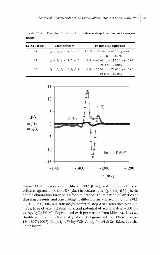
March 19, 2012 17:2 PSP Book - 9in x 6in 11-Ozsoz-c11
Theoretical Fundamentals of Elimination Voltammetry with Linear Scan (EVLS) 361
Table 11.2. Double EVLS functions eliminating two current compo-
nents
EVLS Function Characteristics Double EVLS Equations
E4 Id �= 0; Ik = 0; Ic = 0 d f (I ) = 135.9I1/4 − 407.7I1/2 + 441.6I
− 203.8I2 + 33.97I4
E5 Id = 0; Ik �= 0; Ic = 0 d f (I ) = 46.63I1/4 − 112.6I1/2 + 100.9I
−39.80I2 + 5.830I4
E6 Id = 0; Ik = 0; Ic �= 0 d f (I ) = 23.31I1/4 − 79.60I1/2 + 100.9I
−56.28I2 + 11.66I4
double EVLS
I (μA) EVLS
df(I)
E (mV)
or f(I)or df(I)
Figure 11.2. Linear sweep (black), EVLS (blue), and double EVLS (red)
voltammograms of homo-ODN (dA9) in acetate buffer (pH 5.3). d f (I ) is the
double elimination function E4 for simultaneous elimination of kinetic and
charging currents, and conserving the diffusion current. Scan rates for EVLS:
50, 100, 200, 400, and 800 mV/s, potential step 2 mV, reference scan 200
mV/s, time of accumulation 90 s, and potential of accumulation –100 mV
vs. Ag/AgCl/3M KCl. Reproduced with permission from Mikelova, R., et al.,Double elimination voltammetry of short oligonucleotides, Electroanalysis19, 1807 (2007). Copyright Wiley-VCH Verlag GmbH & Co. KGaA. See also
Color Insert.
March 19, 2012 17:2 PSP Book - 9in x 6in 11-Ozsoz-c11
362 Electrochemical Transducer for Oligonucleotide Biosensor
11.3 EVLS Increasing the Transducer Potential Range
It has been known that the reduction signals of nucleobases are
overlapped in a wide interval of pH by catalytic hydrogen evolution.
Mixtures of adenine (A) and cytosine (C) have been analyzed at low
concentrations by different methods, for example, by differential
pulse polarography [24] or sinusoidal voltammetry [25]. However,
these methods were not fully successful in resolution of individual
signals. The problem of mixed signals of A and C interfering with
hydrogen evolution has also been evaluated by artificial neural
networks, using linear sweep voltammetry and differential pulse
polarography results [26].
For the resolution of reduction signals of A and C in mixtures,
the EVLS functions eliminating the kinetic current component
and conserving diffusion current component were applied [27].
This approach enables extending a potential range (window) and
monitoring voltammetric signals hidden in the discharge current of
the supporting electrolyte. The essential requirements are fulfilled
by two functions: (i) the EVLS function eliminating the kinetic
current Ik and conserving the diffusion current Id (E1) and (ii)
the function eliminating the kinetic and charging currents (Ik and
Id) simultaneously and conserving the diffusion current Id (E4)
(Table. 11.1). Our results proved that EVLS is an electrochemical
method suitable for the analysis of purine and pyrimidine bases,
providing the reduction signals in the close vicinity of background
electrolyte discharge [27].
11.4 EVLS in Connection with Adsorptive StrippingTechnique
From the definition of AdSV it follows that this method is character-
ized by the nature of the accumulation process, where adsorption
plays an important role [28, 29]. In AdSV, the pre-concentration
step is not controlled by electrolysis, but it is accomplished
by analyte adsorption on the working electrode surface or by
reactions with chemically modified electrodes. From the early
1960s, this technique (in connection with dc polarography and
March 19, 2012 17:2 PSP Book - 9in x 6in 11-Ozsoz-c11
EVLS in Connection with Adsorptive Stripping Technique 363
oscillographic polarography without at controlled ac method and
mercury electrodes) was successfully applied to biomacromolecules
analysis, especially to DNA and synthetic polynucleotides (reviewed
in [30] and [31]). Later, it was found that AdSV (in connection with
CV and pulse methods [32–34]) represents a sensitive method for
electrochemical analysis of DNA.
Adsorptive transfer stripping voltammetry (AdTSV) was intro-
duced in 1986 as a new analytical procedure based on the
adsorptive pre-concentration of biomacromolecules on an electrode,
the transfer of the adsorbed layer into a background electrolyte
and subsequent voltammetric analysis [35]. The advantages of
AdTSV were summarized as follows: (i) the method utilizes
differences in adsorbability of substances to their separation, (ii)
due to their strong adsorption, analytes (oligonucleotides) can
be separated from complex media, which are not suitable for
voltammetric analysis of the conventional type, (iii) the interaction
of biomacromolecules immobilized on the surface of the electrode
with substances contained in the solution is possible, and (iv)
all mentioned points can be affected by electrode potential
[35].
An even higher difference was found in stirred solution when the
anodic peak of guanine was measured instead of the cathodic one
[33]. AdSV measuremets of nucleic acids or oligonucleotides were
also performed by square wave voltammetry and ac voltammetry
[36, 37]. Details about AdSV of nucleic acids were summarized in
several reviews [34, 38–43].
As the first EVLS application to adsorbed electroactive species,
the adsorptive stripping voltammetry of thermally denatured DNA
(ssDNA) on a hanging mercury drop electrode (HMDE) was
performed. While the LSV signal of ssDNA at low concentrations
gives a slight indication of the cathodic peak (due to the reduction
of adenine and cytosine residues), the elimination function (elimi-
nating Ic, Ik, and conserving Id) provides a clear peak–counterpeak
signal (Fig. 11.1) [7]. Using this EVLS function E4 it is possible to
determine DNA at concentrations below micrograms per milliliter.
In comparison to the SWV (square-wave voltammetric) signal,
the EVLS signal of ssDNA is one and a half times higher. It was
demonstrated that EVLS, in relation to the accumulation of adsorbed
March 19, 2012 17:2 PSP Book - 9in x 6in 11-Ozsoz-c11
364 Electrochemical Transducer for Oligonucleotide Biosensor
DNA, can considerably contribute to the electrochemical analysis of
nucleic acids [7].
11.4.1 AdS EVLS of Homo- and Hetero-oligonucleotides
The EVLS has been frequently utilized in the electrochemical
research of short synthetic homo- and hetero-ODNs [10, 15, 44].
Similar to the nucleobases on HMDE, EVLS has been able to resolve
the overlapped reduction signals of adenine (A) and cytosine (C)
in mixtures of dA9 and dC9 [10]. On the other hand, while EVLS
function E4 provides for the nucleobases only enhanced signals due
to the transport of electroactive species to the electrode surface
controlled only by diffusion, in case of ODNs a typical peak–
counterpeak-shaped signal is observed, indicating the electrode
process of completely adsorbed species (Fig. 11.1). The height and
potential of LSV and EVLS signals were affected by the dA9/dC9
ratio, the time of accumulation, the stirring during the adsorption,
and pH. The best results were obtained when the adsorption of
ODNs was carried out at −100 mV for accumulation time of 120 s
under stirring. While on LSV curves the only one reduction peak of A
and C residues was observed in all ODNs, EVLS yielded two separate
peaks in dependence on A–C representation and pH. Subsequently,
our effort was aimed at the separation of A and C reduction signals
of hetero-ODNs containing nine nucleotides with different A–C
sequences, but with the same C/A ratio. We found that (i) EVLS can
be used for the resolution of reduction signals of A and C located on
the same ODN chain, and (ii) the EVLS signal is influenced by the A–
C sequence in ODN chain and pH [15]. The best resolution of both
A and C signals was observed for ODN with triple adenines in the
central part of the nonamer (Fig. 11.3).
The resolution of reduction signals of C and A residues in hetero-
ODNs (9-mers and 20-mers) adsorbed from a small volume on
a HMDE was performed by EVLS in combination with the AdTS
procedure [45]. The suggested connection represents a new, original
detection method for ODN biosensors and provides the possibility to
distinguish between neighboring and non-neighboring bases in the
ODN chain.
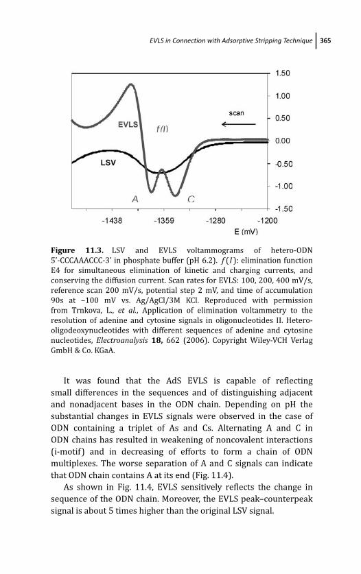
March 19, 2012 17:2 PSP Book - 9in x 6in 11-Ozsoz-c11
EVLS in Connection with Adsorptive Stripping Technique 365
Figure 11.3. LSV and EVLS voltammograms of hetero-ODN
5’-CCCAAACCC-3’ in phosphate buffer (pH 6.2). f (I ): elimination function
E4 for simultaneous elimination of kinetic and charging currents, and
conserving the diffusion current. Scan rates for EVLS: 100, 200, 400 mV/s,
reference scan 200 mV/s, potential step 2 mV, and time of accumulation
90s at –100 mV vs. Ag/AgCl/3M KCl. Reproduced with permission
from Trnkova, L., et al., Application of elimination voltammetry to the
resolution of adenine and cytosine signals in oligonucleotides II. Hetero-
oligodeoxynucleotides with different sequences of adenine and cytosine
nucleotides, Electroanalysis 18, 662 (2006). Copyright Wiley-VCH Verlag
GmbH & Co. KGaA.
It was found that the AdS EVLS is capable of reflecting
small differences in the sequences and of distinguishing adjacent
and nonadjacent bases in the ODN chain. Depending on pH the
substantial changes in EVLS signals were observed in the case of
ODN containing a triplet of As and Cs. Alternating A and C in
ODN chains has resulted in weakening of noncovalent interactions
(i-motif) and in decreasing of efforts to form a chain of ODN
multiplexes. The worse separation of A and C signals can indicate
that ODN chain contains A at its end (Fig. 11.4).
As shown in Fig. 11.4, EVLS sensitively reflects the change in
sequence of the ODN chain. Moreover, the EVLS peak–counterpeak
signal is about 5 times higher than the original LSV signal.
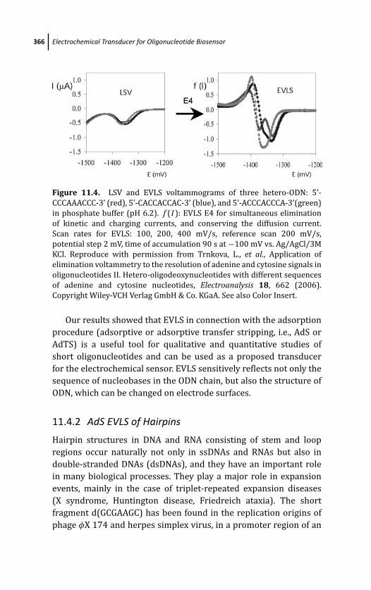
March 19, 2012 17:2 PSP Book - 9in x 6in 11-Ozsoz-c11
366 Electrochemical Transducer for Oligonucleotide Biosensor
Figure 11.4. LSV and EVLS voltammograms of three hetero-ODN: 5’-
CCCAAACCC-3’ (red), 5’-CACCACCAC-3’ (blue), and 5’-ACCCACCCA-3’(green)
in phosphate buffer (pH 6.2). f (I ): EVLS E4 for simultaneous elimination
of kinetic and charging currents, and conserving the diffusion current.
Scan rates for EVLS: 100, 200, 400 mV/s, reference scan 200 mV/s,
potential step 2 mV, time of accumulation 90 s at −100 mV vs. Ag/AgCl/3M
KCl. Reproduce with permission from Trnkova, L., et al., Application of
elimination voltammetry to the resolution of adenine and cytosine signals in
oligonucleotides II. Hetero-oligodeoxynucleotides with different sequences
of adenine and cytosine nucleotides, Electroanalysis 18, 662 (2006).
Copyright Wiley-VCH Verlag GmbH & Co. KGaA. See also Color Insert.
Our results showed that EVLS in connection with the adsorption
procedure (adsorptive or adsorptive transfer stripping, i.e., AdS or
AdTS) is a useful tool for qualitative and quantitative studies of
short oligonucleotides and can be used as a proposed transducer
for the electrochemical sensor. EVLS sensitively reflects not only the
sequence of nucleobases in the ODN chain, but also the structure of
ODN, which can be changed on electrode surfaces.
11.4.2 AdS EVLS of Hairpins
Hairpin structures in DNA and RNA consisting of stem and loop
regions occur naturally not only in ssDNAs and RNAs but also in
double-stranded DNAs (dsDNAs), and they have an important role
in many biological processes. They play a major role in expansion
events, mainly in the case of triplet-repeated expansion diseases
(X syndrome, Huntington disease, Friedreich ataxia). The short
fragment d(GCGAAGC) has been found in the replication origins of
phage φX 174 and herpes simplex virus, in a promoter region of an
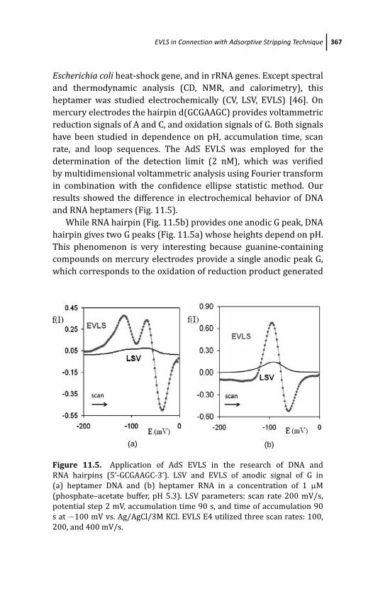
March 19, 2012 17:2 PSP Book - 9in x 6in 11-Ozsoz-c11
EVLS in Connection with Adsorptive Stripping Technique 367
Escherichia coli heat-shock gene, and in rRNA genes. Except spectral
and thermodynamic analysis (CD, NMR, and calorimetry), this
heptamer was studied electrochemically (CV, LSV, EVLS) [46]. On
mercury electrodes the hairpin d(GCGAAGC) provides voltammetric
reduction signals of A and C, and oxidation signals of G. Both signals
have been studied in dependence on pH, accumulation time, scan
rate, and loop sequences. The AdS EVLS was employed for the
determination of the detection limit (2 nM), which was verified
by multidimensional voltammetric analysis using Fourier transform
in combination with the confidence ellipse statistic method. Our
results showed the difference in electrochemical behavior of DNA
and RNA heptamers (Fig. 11.5).
While RNA hairpin (Fig. 11.5b) provides one anodic G peak, DNA
hairpin gives two G peaks (Fig. 11.5a) whose heights depend on pH.
This phenomenon is very interesting because guanine-containing
compounds on mercury electrodes provide a single anodic peak G,
which corresponds to the oxidation of reduction product generated
(a) (b)
Figure 11.5. Application of AdS EVLS in the research of DNA and
RNA hairpins (5’-GCGAAGC-3’). LSV and EVLS of anodic signal of G in
(a) heptamer DNA and (b) heptamer RNA in a concentration of 1 μM
(phosphate–acetate buffer, pH 5.3). LSV parameters: scan rate 200 mV/s,
potential step 2 mV, accumulation time 90 s, and time of accumulation 90
s at −100 mV vs. Ag/AgCl/3M KCl. EVLS E4 utilized three scan rates: 100,
200, and 400 mV/s.
March 19, 2012 17:2 PSP Book - 9in x 6in 11-Ozsoz-c11
368 Electrochemical Transducer for Oligonucleotide Biosensor
at negative potentials [47–49]. The difference in electrochemical
behavior between DNA and RNA mini-hairpins may be explained by
the conformational difference (DNA B form and RNA A form) in the
stem structures [50].
11.5 EVLS of Nucleobases and Oligonucleotides in thePresence of Copper Ions
The purine ring is reducible on mercury electrodes in slightly
acidic medium in a wide pH scale. The electrode redox mechanism
is known and was reviewed [51, 52]. Electrochemical analysis
based on adsorptive properties of long ODNs containing purine
nucleobases, where the transfer technique involves an electrode
transfer step, cannot be applied to monomeric units of nucleotides
or nucleobases because these substances have much less absorba-
bility on electrode surfaces compared to long ODNs. New analyt-
ical approaches were developed to overcome this disadvantage.
One possibility is the interaction of purine nucleobases or their
derivatives with metal ions for example, Cu(II) ions resulting
under suitable conditions in the formation of the complex Cu(I)–
purine. In this reaction, the required monovalent copper ions are
generated electrochemically in the vicinity of electrode surface. The
formed complex is adsorbed on an electrode surface and in the
following reaction step is stripped from the surface by changing
the potential either cathodically (mercury electrodes) or anodically
(carbon electrodes). In both cases, the stripping process resulted in
the formation of a new peak on the voltammetric curve and in the
enhancement of the corresponding redox signal. Using EVLS to the
Cu(I)–purine complex analysis, the more sensitive determination of
purine derivatives was achieved.
11.5.1 Mercury and Mercury-Modified Electrodes
Under specific conditions, adenine forms an intermediate Cu(I)–
adenine species which is sparingly soluble and adsorbs strongly on
the mercury surface [53–55]. The reaction involves electrochemical
reduction of Cu(II) to Cu(I) at a suitable potential and the reaction
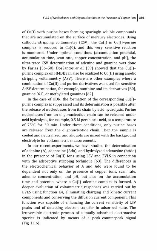
March 19, 2012 17:2 PSP Book - 9in x 6in 11-Ozsoz-c11
EVLS of Nucleobases and Oligonucleotides in the Presence of Copper Ions 369
of Cu(I) with purine bases forming sparingly soluble compounds
that are accumulated on the surface of mercury electrodes. Using
cathodic stripping voltammetry (CSV), the Cu(I) in Cu(I)–purine
complex is reduced to Cu(0), and this very sensitive reaction
is monitored. Under optimal conditions (accumulation potential,
accumulation time, scan rate, copper concentration, and pH), the
ultra-trace CSV determination of adenine and guanine was done
by Farias [56–58]. DosSantos et al. [59] showed that the Cu(I)–
purine complex on HMDE can also be oxidized to Cu(II) using anodic
stripping voltammetry (ASV). There are other examples where a
combination of Cu(II) and purine derivatives was used for sensitive
AdSV determination, for example, xanthine and its derivatives [60],
guanine [61], or methylated guanines [62].
In the case of ODN, the formation of the corresponding Cu(I)–
purine complex is suppressed and its determination is possible after
the release of nucleobases from its chain by acid hydrolysis. Purine
nucleobases from an oligonucleotide chain can be released under
acid hydrolysis, for example, 0.5 M perchloric acid, at a temperature
of 75◦C for 30 min. Under these conditions, only purine bases
are released from the oligonucleotide chain. Then the sample is
cooled and neutralized, and aliquots are mixed with the background
electrolyte for voltammetric measurements.
In our recent experiments, we have studied the determination
of adenine (A), adenosine (Ado), and hydrolyzed adenosine (hAdo)
in the presence of Cu(II) ions using LSV and EVLS in connection
with the adsorptive stripping technique [63]. The differences in
the electrochemical behavior of A and Ado were found to be
dependent not only on the presence of copper ions, scan rate,
adenine concentration, and pH, but also on the accumulation
time and potential where a Cu(I)–adenine complex is formed. A
deeper evaluation of voltammetric responses was carried out by
EVLS using function E4, eliminating charging and kinetic current
components and conserving the diffusion current component. This
function was capable of enhancing the current sensitivity of LSV
peaks and of detecting electron transfer in adsorbed state. The
irreversible electrode process of a totally adsorbed electroactive
species is indicated by means of a peak–counterpeak signal
(Fig. 11.6).
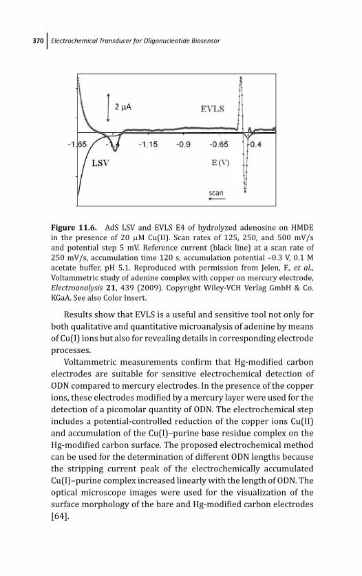
March 19, 2012 17:2 PSP Book - 9in x 6in 11-Ozsoz-c11
370 Electrochemical Transducer for Oligonucleotide Biosensor
Figure 11.6. AdS LSV and EVLS E4 of hydrolyzed adenosine on HMDE
in the presence of 20 μM Cu(II). Scan rates of 125, 250, and 500 mV/s
and potential step 5 mV. Reference current (black line) at a scan rate of
250 mV/s, accumulation time 120 s, accumulation potential –0.3 V, 0.1 M
acetate buffer, pH 5.1. Reproduced with permission from Jelen, F., et al.,Voltammetric study of adenine complex with copper on mercury electrode,
Electroanalysis 21, 439 (2009). Copyright Wiley-VCH Verlag GmbH & Co.
KGaA. See also Color Insert.
Results show that EVLS is a useful and sensitive tool not only for
both qualitative and quantitative microanalysis of adenine by means
of Cu(I) ions but also for revealing details in corresponding electrode
processes.
Voltammetric measurements confirm that Hg-modified carbon
electrodes are suitable for sensitive electrochemical detection of
ODN compared to mercury electrodes. In the presence of the copper
ions, these electrodes modified by a mercury layer were used for the
detection of a picomolar quantity of ODN. The electrochemical step
includes a potential-controlled reduction of the copper ions Cu(II)
and accumulation of the Cu(I)–purine base residue complex on the
Hg-modified carbon surface. The proposed electrochemical method
can be used for the determination of different ODN lengths because
the stripping current peak of the electrochemically accumulated
Cu(I)–purine complex increased linearly with the length of ODN. The
optical microscope images were used for the visualization of the
surface morphology of the bare and Hg-modified carbon electrodes
[64].
March 19, 2012 17:2 PSP Book - 9in x 6in 11-Ozsoz-c11
EVLS of Nucleobases and Oligonucleotides in the Presence of Copper Ions 371
11.5.2 Solid Electrodes
There are many types of solid electrodes which are used for the
determination of purine nucleobases, their derivatives, and ODNs
containing purines in the presence of Cu(II). The glassy carbon
electrode (GCE) was used for the electrochemical anodic stripping of
adenine and guanine in Cu(II) solution [65]. It was found that Cu(II)
can be reduced to Cu(I) and the generated Cu(I) reacts with A and G
to accumulate on the GCE as an insoluble compound. Reoxidation of
Cu(I) to Cu(II) at positive potentials gives a large oxidation current
for the base. The same electrode was used for an ultra-trace assay of
some derivatives of nucleic acid bases in Cu(II) solution. Promising
results were obtained also for xanthine determination [66]. The
copper solid amalgam electrode is suitable for a sensitive analysis of
A at very low concentrations. Compared to HMDE, the voltammetric
peak resulting from reduction of the Cu(I)–adenine complex with
the increasing concentration of A shifted to more negative potentials,
indicating the adsorption of this complex on the electrode surface
[67].
Using a paraffin-impregnated graphite electrode (PIGE) and
mercury-modified pyrolytic graphite electrode with basal orien-
tation (Hg-PGEb) Cu(I)–purine complex was studied by LSV in
connection with EVLS [68]. According to the elimination function
E4, the first cathodic peak corresponds to the reduction Cu(II) +e− → Cu(I) with the possibility of fast disproportionation 2Cu(I)
→ Cu(II)+ Cu(0). Anodic stripping voltammetry (ASV) on PIGE and
cathodic stripping voltammetry (CSV) on Hg-PGEb were carried out
at potentials where the reduction of copper ions took place and
Cu(I)–purine complexes were formed.
Electrochemical oxidations of aminopurines (adenine,
2-aminopurine, 2,6-diaminopurine) and their complexes with Cu(I)
were investigated on a pencil graphite electrode (PeGE) by LSV
and EVLS [69]. The anodic process of the sparingly soluble Cu(I)–
aminopurine complex, corresponding to the oxidation of Cu(I) to
Cu(II), takes place in the potential range between 0.4 and 0.5 V. At
more positive potentials, the aminopurines provide voltammetric
peaks resulting from the oxidation of the purine ring. The appro-
priate complex of Cu(I)–aminopurine has a synergic effect on the
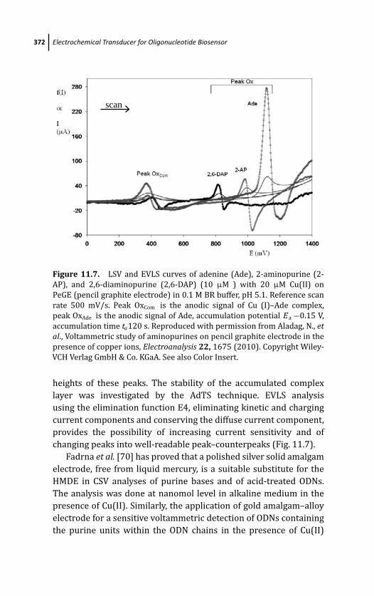
March 19, 2012 17:2 PSP Book - 9in x 6in 11-Ozsoz-c11
372 Electrochemical Transducer for Oligonucleotide Biosensor
scan
Figure 11.7. LSV and EVLS curves of adenine (Ade), 2-aminopurine (2-
AP), and 2,6-diaminopurine (2,6-DAP) (10 μM ) with 20 μM Cu(II) on
PeGE (pencil graphite electrode) in 0.1 M BR buffer, pH 5.1. Reference scan
rate 500 mV/s. Peak OxCom is the anodic signal of Cu (I)–Ade complex,
peak OxAde is the anodic signal of Ade, accumulation potential Ea −0.15 V,
accumulation time ta120 s. Reproduced with permission from Aladag, N., etal., Voltammetric study of aminopurines on pencil graphite electrode in the
presence of copper ions, Electroanalysis 22, 1675 (2010). Copyright Wiley-
VCH Verlag GmbH & Co. KGaA. See also Color Insert.
heights of these peaks. The stability of the accumulated complex
layer was investigated by the AdTS technique. EVLS analysis
using the elimination function E4, eliminating kinetic and charging
current components and conserving the diffuse current component,
provides the possibility of increasing current sensitivity and of
changing peaks into well-readable peak–counterpeaks (Fig. 11.7).
Fadrna et al. [70] has proved that a polished silver solid amalgam
electrode, free from liquid mercury, is a suitable substitute for the
HMDE in CSV analyses of purine bases and of acid-treated ODNs.
The analysis was done at nanomol level in alkaline medium in the
presence of Cu(II). Similarly, the application of gold amalgam–alloy
electrode for a sensitive voltammetric detection of ODNs containing
the purine units within the ODN chains in the presence of Cu(II)
March 19, 2012 17:2 PSP Book - 9in x 6in 11-Ozsoz-c11
Conclusions 373
ions was described [71]. The proposed electrochemical method was
used either for the detection of different ODN lengths containing
only adenine units (with the number of adenine units within 10 and
80) or for the determination of the number of purine units within
the 30-mer ODNs containing a random sequence segments involving
both the purine and pyrimidine units. A good correlation between
the content of purine units with the whole length of different
30-mer ODNs and the current intensity of the electrochemically
accumulated complexes was found. The sensitive detection of
different ODNs containing the purine units in their chains in the
presence of copper can also be performed at other amalgam
alloys, for example, the platinum amalgam–alloy electrode, copper
amalgam–alloy electrode, and silver amalgam–alloy electrode [71].
Copper-enhanced label-free anodic stripping detection of guanine
and adenine bases in acid-hydrolyzed DNA at anodically oxidized
boron-doped diamond electrode (BDDE) has been published [72].
The BDDE was successfully applied in a three-electrode micro-cell
in which a 50 μL drop of the analyte solution can be efficiently
stirred during the accumulation step by the streaming of an inert
gas. Accelerated mass transport due to the solution motion in
the presence of copper resulted in enhancement of the guanine
oxidation signal, allowing easy detection of 25 fmol of ODNs. It
was also shown that the edge-plane pyrolytic graphite electrode,
whose surface was mechanically roughened, enables voltammetric
analysis of purine nucleobases, acid-hydrolyzed synthetic ODNs, and
a nonhydrolyzed plasmid DNA [73]. In the presence of copper ions,
they caused a strong enhancement of the purine oxidation responses
at fine-polished carbon electrodes.
11.6 Conclusions
EVLS is an unconventional, perspective electrochemical method
capable of eliminating or conserving selected partial currents
(diffusion current, charging current, kinetic current, etc.) from the
total voltammetric current and thereby enhancing the sensitivity
and improving the resolution of the measured voltammetric signals
[5, 6]. EVLS in combination with the adsorptive stripping or
adsorptive transfer stripping (AdS or AdTS) techniques has been
March 19, 2012 17:2 PSP Book - 9in x 6in 11-Ozsoz-c11
374 Electrochemical Transducer for Oligonucleotide Biosensor
designed for electrochemically fast, sensitive, selective, and low-
cost detection and characterization of surface active compounds
[6, 7, 15, 21]. To obtain sensitive EVLS signals, the elimination
method analyzes voltammetric curves measured at different scan
rates and in connection with adsorptive techniques works with
small amount of samples utilizing strong adsorption of analyte on
the electrode surface. EVLS was applied mostly to the resolution of
reduction signals of adenine (A) and cytosine (C) in short synthetic
homo- and hetero-ODNs [10, 15, 44, 45], but preliminary results
showed that the chosen elimination functions would be useful for
the study of anodic processes, especially for the anodic processes
of guanine [47–49]. For an adsorbed electroactive substance, the
elimination function E4 (the simultaneous elimination of charging
and kinetic currents, and conservation of diffusion current) gives
a well-readable peak–counterpeak, which has been successfully
utilized in the analysis of overlapped reduction signals of A and
C on HMDE [10, 15, 44, 45]. Using the AdTS procedure, ODNs
were immobilized at the HMDE surface from a small drop of the
analyzed solution (5 μL); then the ODN-modified electrode was
washed and immersed into buffer solutions (not containing ODN)
to perform voltammetric measurements [35]. Our new analytical
approach contributed to the transformation of LSV data (overlapped
signal) to EVLS data (resolved signal).
The sparingly soluble complex of Cu(I)–purine reduced at
mercury electrodes and oxidized at carbon electrodes (carbon paste
or carbon pencil electrodes) was recently utilized for the sensitive
detection of purine derivatives [69]. It was found that this complex
has a synergic effect for reduction or oxidation of corresponding
nucleobases because it brings more electroactive materials to the
electrode surfaces. Purine signals processed AdS and AdTS EVLS
and were 15 times more enhanced than the original signal. The
advantage of mercury and carbon electrodes is a good adsorption
capability of this complex on their surface.
In summary, our research showed that the EVLS is not limited to
mercury electrodes, to reduction processes, or to the elimination of
one current component only. Voltammetric signals of purine deriva-
tives at carbon electrodes are amplified using our approaches. Com-
pared to elimination in various combinations (different functions
March 19, 2012 17:2 PSP Book - 9in x 6in 11-Ozsoz-c11
References 375
elimination, Table 11.1), the electrochemical process can be eval-
uated in detail. Using kinetic current component elimination, the
extending potential window can be achieved. Generally, AdS EVLS or
AdTS EVLS E4 peak–counterpeaks are an order of magnitude higher
than their corresponding LSV signals and, moreover, do not require
baseline correction.
It was found that EVLS is capable to detect (i) minor signals
hidden in major ones, (ii) small changes in ODN structure and the
interaction between ODN and electrode surface, and (iii) potentially
closed signals (resolution of overlapped peaks). On the basis of
the above-mentioned advantages, EVLS in connection with the
adsorption procedure fulfills the requirements for a perspective and
promising tool for qualitative and quantitative studies in bioanalysis
in bio- and nanotechnologies. Therefore, the implementation of
EVLS in electrochemical analyzers should be of great interest.
Acknowledgement
This work was supported by the Ministry of Education, Youth and
Sports of the Czech Republic (INCHEMBIOL MSM0021622412 and
BIO-ANAL-MED LC06035), the Academy of Sciences of the Czech
Republic (grant A400040804), the Czech Grant Foundation GACR
(P205/10/2378), and institutional research plans of the Institute of
Biophysics (AV0Z50040507, AV0Z50040702).
References
1. R. N. Adams, Electrochemistry at solid electrodes Marcel Dekker, New
York (1969).
2. C. M. A. Brett and A. M. O. Brett, Electrochemistry. Principles, Methods,and Applications Oxford University Press, Oxford (1993).
3. Z. Galus, Fundamentals of Electrochemical Analysis Ellis Horwood and
Polish Scientific Publishers, New York and Warsaw (1994).
4. A. J. Bard and L. R. Faulkner, Electrochemical methods: Fundamentals andapplications, John Wiley and Sons, New York (2000).
5. O. Dracka, J. Electroanal. Chem. 402, 18 (1996).
March 19, 2012 17:2 PSP Book - 9in x 6in 11-Ozsoz-c11
376 Electrochemical Transducer for Oligonucleotide Biosensor
6. L. Trnkova and O. Dracka, J. Electroanal. Chem. 413, 123 (1996).
7. L. Trnkova, R. Kizek, and O. Dracka, Electroanalysis 12, 905 (2000).
8. L. Trnkova, Talanta 56, 887 (2002).
9. S. Sander, T. Navratil, and L. Novotny, Electroanalysis 15, 1513 (2003).
10. L. Trnkova, F. Jelen, and I. Postbieglova, Electroanalysis 15, 1529 (2003).
11. J. W. Kang, Z. F. Li, X. Q. Lu, and Y. S. Wang, Electrochim. Acta 50, 19
(2004).
12. R. Orinakova, L. Trnkova, M. Galova, and M. Supicova, Electrochim. Acta49, 3587 (2004).
13. L. Trnkova, J. Electroanal. Chem. 582, 258 (2005).
14. I. Sestakova and T. Navratil, Bioinorg. Chem. Appl. 3, 43 (2005).
15. L. Trnkova, F. Jelen, and I. Postbieglova, Electroanalysis 18, 662 (2006).
16. T. Navratil, Z. Senholdova, K. Shanmugam, and J. Barek, Electroanalysis18, 201 (2006).
17. N. Serrano, I. Sestakova, and J. M. Diaz-Cruz, Electroanalysis 18, 169
(2006).
18. R. Rozik and L. Trnkova, J. Electroanal. Chem. 593, 247 (2006).
19. Z. F. Li, J. W. Kang, and X. Q. Lu, Nucleosides Nucleotides & Nucleic Acids26, 9 (2007).
20. K. Peckova, J. Barek, T. Navratil, B. Yosypchuk, and J. Zima, Anal. Lett. 42,
2339 (2009).
21. L. Trnkova, in Utilizing of Bio-Electrochemical and Mathematical Methodsin Biological Research (V. Adam and R. Kizek, eds.), Research Signpost,
Kerala, India 51 (2007).
22. N. Serrano, K. Klosova, and L. Trnkova, Electroanalysis 22, 2071
(2010).
23. R. Mikelova, L. Trnkova, and F. Jelen, Electroanalysis 19, 1807 (2007).
24. T. E. Cummings, J. R. Fraser, and P. J. Elving, Anal. Chem. 52, 558 (1980).
25. P. Singhal and W. G. Kuhr, Anal. Chem. 69, 3552 (1997).
26. E. Cukrowska, L. Trnkova, R. Kizek, and J. Havel, J. Electroanal. Chem.503, 117 (2001).
27. L. Trnkova, J. Friml, and O. Dracka, Bioelectrochem. 54, 131 (2001).
28. R. Kalvoda and M. Kopanica, Pure Appl. Chem. 61, 97 (1989).
29. J. Wang, Stripping analysis. Principles, instrumentation and applications,
VCH Publisher, Derfield Beech, Florida (1985).
30. J. Kuta and E. Palecek, in Topics in Bioelectrochemistry and Bioenergetics.(G. Milazzo, ed.), London, 5, 1 (1983).
March 19, 2012 17:2 PSP Book - 9in x 6in 11-Ozsoz-c11
References 377
31. E. Palecek, in Topics Bioelectrochem. Bioenerg. (G. Milazzo, ed.), London,
5, 65 (1983).
32. P. Boublikova, F. Jelen, and E. Palecek, Stud. biophys. 114, 83 (1986).
33. E. Palecek, P. Boublikova, and F. Jelen, Anal. Chim. Acta 187, 99 (1986).
34. E. Palecek, Electroanalysis 8, 7 (1996).
35. E. Palecek and I. Postbieglova, J. Electroanal. Chem. 214, 359 (1986).
36. F. Jelen, V. Vetterl, P. Belusa, and S. Hason, Electroanalysis 12, 987 (2000).
37. F. Jelen, M. Tomschik, and E. Palecek, J. Electroanal. Chem. 423, 141
(1997).
38. E. Palecek, in Encyclopedia of Analytical Science 2e (C. F. Poole, ed.),
Elsevier, London, 399 (2005).
39. E. Palecek and F. Jelen, Perspectives in Bioanalysysis. Vol. 1 Electrochem-istry of nucleic acids and proteins. Towards electrochemical sensors forgenomics and proteomics 1, 74 (2005).
40. E. Palecek, Talanta 56, 807 (2002).
41. E. Palecek, M. Fojta, and F. Jelen, and V. Vetterl, Bioelectrochemistry, in
Encyclopedia of Electrochem. (A. J. Bard and J. Stratsman, eds.), Wiley-
VCH Verlag, Weiheim, 9, 365 (2002).
42. E. Palecek and M. Fojta, Anal. Chem. 73, 74A (2001).
43. E. Palecek, F. Jelen, C. Teijeiro, V. Fucik, and T. M. Jovin, Anal. Chim. Acta273, 175 (1993).
44. R. Mikelova, L. Trnkova, F. Jelen, V. Adam, and R. Kizek, Electroanalysis19, 348 (2007).
45. L. Trnkova, F. Jelen, J. Petrlova, V. Adam, D. Potesil, and R. Kizek, Sensors5, 448 (2005).
46. L. Trnkova, I. Postbieglova, and M. Holik, Bioelectrochem. 63, 25 (2004).
47. L. Trnkova, M. Studnickova, and E. Palecek, Bioelectrochem. Bioenerg. 7,
643 (1980).
48. E. Palecek, F. Jelen, and L. Trnkova, Gen. Physiol. Biophys. 5, 315 (1986).
49. M. Studnickova, L. Trnkova, J. Zetek, and Z. Glatz, Bioelectrochem.Bioenerg. 21, 83 (1989).
50. V. P. Antao, S. Y. Lai, and I. Tinoco, Nucl. Acids Res. 19, 5901 (1991).
51. G. Dryhurst, Electrochemistry of Biological Molecules, Academic Press,
New York (1977).
52. S. Palanti, G. Marrazza, and M. Mascini, Anal. Lett. 29, 2309 (1996).
53. S. Glodowski, R. Bilewicz, and Z. Kublik, Anal. Chim. Acta 186, 39 (1986).
54. S. Glodowski, R. Bilewicz, and Z. Kublik, Anal. Chim. Acta 201, 11 (1987).
March 19, 2012 17:2 PSP Book - 9in x 6in 11-Ozsoz-c11
378 Electrochemical Transducer for Oligonucleotide Biosensor
55. R. Bilewicz, S. Glodowski, and Z. Kublik, J. Electroanal. Chem. 274, 201
(1989).
56. P. A. M. Farias, A. D. Wagener, and A. A. Castro, Talanta 55, 281 (2001).
57. P. A. M. Farias, A. D. R. Wagener, M. B. R. Bastos, A. T. da Silva, and A. A.
Castro, Talanta 61, 829 (2003).
58. P. A. M. Farias, A. D. R. Wagener, and A. A. Castro, Anal. Lett. 34, 2125
(2001).
59. M. M. C. dosSantos, C. M. L. F. Lopes, and M. L. S. Goncalves,
Bioelectrochem. Bioenerg. 39, 55 (1996).
60. R. M. Shubietah, A. Z. Abuzuhri, and A. G. Fogg, Electroanalysis 7, 975
(1995).
61. R. M. Shubietah, A. Z. Abuzuhri, and A. G. Fogg, Fres. J. Anal. Chem. 348,
754 (1994).
62. R. M. Shubietah, A. Z. A. Zuhri, and A. G. Fogg, Anal. Lett. 27, 1123 (1994).
63. F. Jelen, A. Kourilova, S. Hason, R. Kizek, and L. Trnkova, Electroanalysis21, 439 (2009).
64. S. Hason, F. Jelen, L. Fojt, and V. Vetterl, J. Electroanal. Chem. 577, 263
(2005).
65. H. Shiraishi and R. Takahashi, Bioelectrochem. Bioenerg. 31, 203 (1993).
66. M. S. Ibrahim, Y. M. Temerk, M. M. Kamal, G. A. W. Ahmed, and H. S. M.
Ibrahim, Microchim. Acta 144, 249 (2004).
67. B. Yosypchuk and L. Novotny, Electroanalysis 15, 121 (2003).
68. L. Trnkova, L. Zerzankova, F. Dycka, R. Mikelova, and F. Jelen, Sensors 8,
429 (2008).
69. N. Aladag, L. Trnkova, A. Kourilova, M. Ozsoz, and F. Jelen, Electroanalysis22, 1675 (2010).
70. R. Fadrna, B. Yosypchuk, M. Fojta, T. Navratil, and L. Novotny, Anal. Lett.37, 399 (2004).
71. S. Hason and V. Vetterl, Talanta 69, 572 (2006).
72. S. Hason, H. Pivonkova, V. Vetterl, and M. Fojta, Anal. Chem. 80, 2391
(2008).
73. S. Hason, L. Fojt, P. Sebest, and M. Fojta, Electroanalysis 21, 666 (2009).
March 20, 2012 18:34 PSP Book - 9in x 6in 12-Ozsoz-c12
Chapter 12
Electrochemical DNA Biosensors forDetection of Compound-DNAInteractions
D. Ozkan-Ariksoysal, P. Kara, and M. OzsozDepartment of Analytical Chemistry, Faculty of Pharmacy, Ege University,35100, Bornova, Izmir, [email protected]
The interactions of some compounds such as anticancer drugs with
DNA have been performed by a variety of techniques. In recent
times electrochemical DNA biosensor systems have been taking an
increasing interest in the analysis of compound-DNA interactions for
understanding the action mechanism of many chemical molecules
due to their high sensitivity, portability, low-cost structure, single-
use property, and compatibility with microfabrication technology.
Based on these electrochemical methods, binding of compounds
onto DNA and/or general DNA damage occurred by these com-
pounds, have been identified by using the voltammetric signals
of guanine, adenine, or related compound molecules. In most of
these applications for the detection of compound-DNA interactions,
anticancer drugs have been studied because of their known effects
on DNA molecule.
Electrochemical DNA BiosensorsEdited by Mehmet OzsozCopyright c© 2012 Pan Stanford Publishing Pte. Ltd.ISBN 978-981-4241-77-9 (Hardcover), 978-981-4303-98-9 (eBook)www.panstanford.com
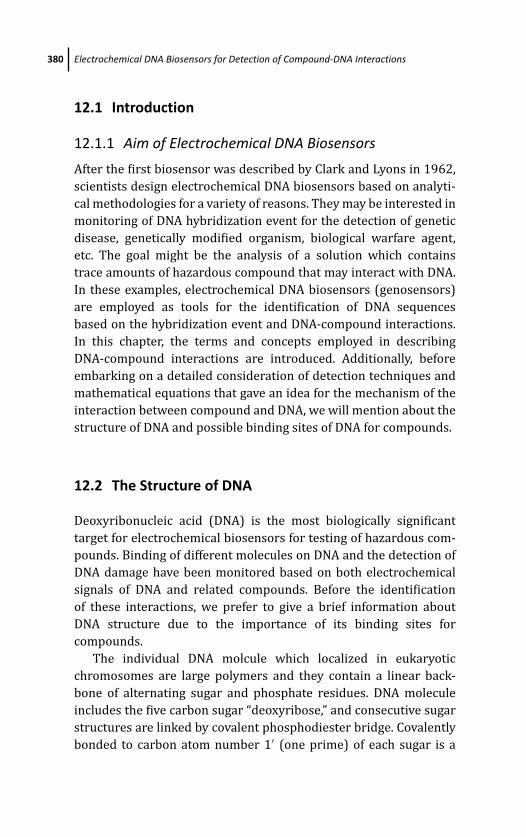
March 20, 2012 18:34 PSP Book - 9in x 6in 12-Ozsoz-c12
380 Electrochemical DNA Biosensors for Detection of Compound-DNA Interactions
12.1 Introduction
12.1.1 Aim of Electrochemical DNA Biosensors
After the first biosensor was described by Clark and Lyons in 1962,
scientists design electrochemical DNA biosensors based on analyti-
cal methodologies for a variety of reasons. They may be interested in
monitoring of DNA hybridization event for the detection of genetic
disease, genetically modified organism, biological warfare agent,
etc. The goal might be the analysis of a solution which contains
trace amounts of hazardous compound that may interact with DNA.
In these examples, electrochemical DNA biosensors (genosensors)
are employed as tools for the identification of DNA sequences
based on the hybridization event and DNA-compound interactions.
In this chapter, the terms and concepts employed in describing
DNA-compound interactions are introduced. Additionally, before
embarking on a detailed consideration of detection techniques and
mathematical equations that gave an idea for the mechanism of the
interaction between compound and DNA, we will mention about the
structure of DNA and possible binding sites of DNA for compounds.
12.2 The Structure of DNA
Deoxyribonucleic acid (DNA) is the most biologically significant
target for electrochemical biosensors for testing of hazardous com-
pounds. Binding of different molecules on DNA and the detection of
DNA damage have been monitored based on both electrochemical
signals of DNA and related compounds. Before the identification
of these interactions, we prefer to give a brief information about
DNA structure due to the importance of its binding sites for
compounds.
The individual DNA molcule which localized in eukaryotic
chromosomes are large polymers and they contain a linear back-
bone of alternating sugar and phosphate residues. DNA molecule
includes the five carbon sugar “deoxyribose,” and consecutive sugar
structures are linked by covalent phosphodiester bridge. Covalently
bonded to carbon atom number 1′ (one prime) of each sugar is a
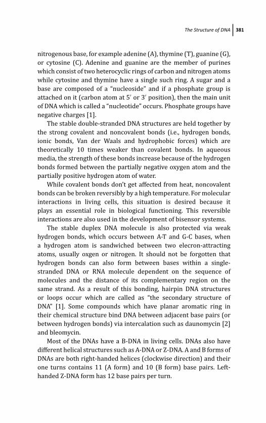
March 20, 2012 18:34 PSP Book - 9in x 6in 12-Ozsoz-c12
The Structure of DNA 381
nitrogenous base, for example adenine (A), thymine (T), guanine (G),
or cytosine (C). Adenine and guanine are the member of purines
which consist of two heterocyclic rings of carbon and nitrogen atoms
while cytosine and thymine have a single such ring. A sugar and a
base are composed of a “nucleoside” and if a phosphate group is
attached on it (carbon atom at 5′ or 3′ position), then the main unit
of DNA which is called a “nucleotide” occurs. Phosphate groups have
negative charges [1].
The stable double-stranded DNA structures are held together by
the strong covalent and noncovalent bonds (i.e., hydrogen bonds,
ionic bonds, Van der Waals and hydrophobic forces) which are
theoretically 10 times weaker than covalent bonds. In aqueous
media, the strength of these bonds increase because of the hydrogen
bonds formed between the partially negative oxygen atom and the
partially positive hydrogen atom of water.
While covalent bonds don’t get affected from heat, noncovalent
bonds can be broken reversibly by a high temperature. For molecular
interactions in living cells, this situation is desired because it
plays an essential role in biological functioning. This reversible
interactions are also used in the development of bisensor systems.
The stable duplex DNA molecule is also protected via weak
hydrogen bonds, which occurs between A-T and G-C bases, when
a hydrogen atom is sandwiched between two elecron-attracting
atoms, usually oxgen or nitrogen. It should not be forgotten that
hydrogen bonds can also form between bases within a single-
stranded DNA or RNA molecule dependent on the sequence of
molecules and the distance of its complementary region on the
same strand. As a result of this bonding, hairpin DNA structures
or loops occur which are called as “the secondary structure of
DNA” [1]. Some compounds which have planar aromatic ring in
their chemical structure bind DNA between adjacent base pairs (or
between hydrogen bonds) via intercalation such as daunomycin [2]
and bleomycin.
Most of the DNAs have a B-DNA in living cells. DNAs also have
different helical structures such as A-DNA or Z-DNA. A and B forms of
DNAs are both right-handed helices (clockwise direction) and their
one turns contains 11 (A form) and 10 (B form) base pairs. Left-
handed Z-DNA form has 12 base pairs per turn.
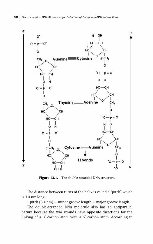
March 20, 2012 18:34 PSP Book - 9in x 6in 12-Ozsoz-c12
382 Electrochemical DNA Biosensors for Detection of Compound-DNA Interactions
Figure 12.1. The double-stranded DNA structure.
The distance between turns of the helix is called a “pitch” which
is 3.4 nm long.
1 pitch (3.4 nm) = minor groove length + major groove length
The double-stranded DNA molecule also has an antiparallel
nature because the two strands have opposite directions for the
linking of a 3′ carbon atom with a 5′ carbon atom. According to

March 20, 2012 18:34 PSP Book - 9in x 6in 12-Ozsoz-c12
Natural Electronalytical Characterictics of DNA 383
2 nm
minor groove
major groove
B DNA form
3.4 nm(1 pitch)
Figure 12.2. The double helical structure of B-DNA. One pitch represents
10 nucleotides which are composed of a single turn of DNA. See also Color
Insert.
the Watson-Crick model, base composition of DNA is not random,
total amount of G equals to the total amount of C, and similarly total
amount of A and T are equal based on the complementary rule [1].
12.3 Natural Electronalytical Characterictics of DNA
The electroactivity of purine and pyrimidine bases were found by
Emil Palecek in 1958. While bases have electroactive properties
and they are able to receive reduction and/or oxidation, other
components of nucleic acids such as sugar and phosphate groups are
electroinactive (reviewed in Refs. 3–6). In these reviews, oxidation
parts of A and G [6] and reduction parts of A, C, and G [3–6] were
shown besides the effect of secondary structure of DNA on A and C
reduction signals at mercury electrode.
Carbon-based electrodes are less sensitive to changes in DNA
structure [4, 7, 8]. It was shown that G and A can be detected at
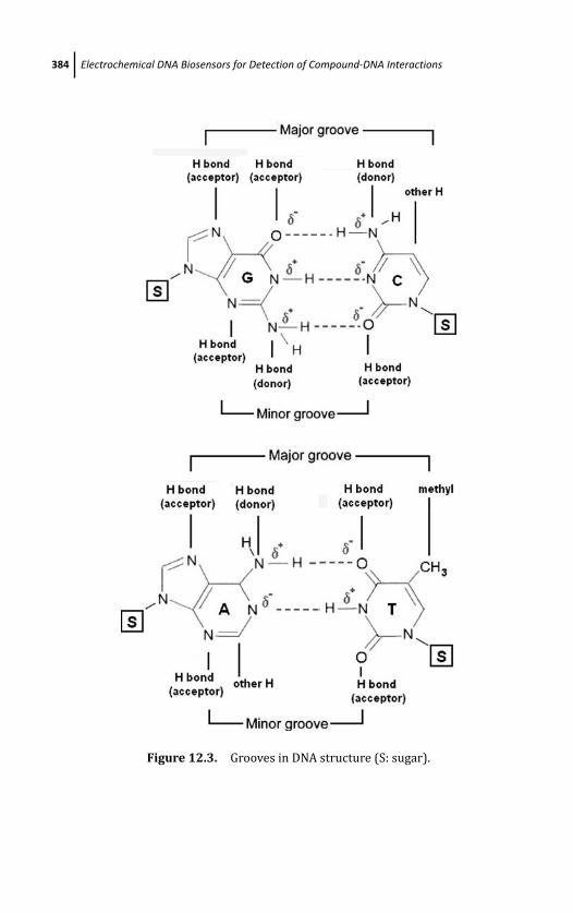
March 20, 2012 18:34 PSP Book - 9in x 6in 12-Ozsoz-c12
384 Electrochemical DNA Biosensors for Detection of Compound-DNA Interactions
Figure 12.3. Grooves in DNA structure (S: sugar).
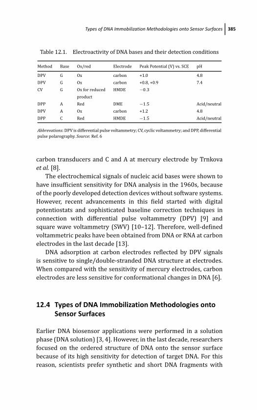
March 20, 2012 18:34 PSP Book - 9in x 6in 12-Ozsoz-c12
Types of DNA Immobilization Methodologies onto Sensor Surfaces 385
Table 12.1. Electroactivity of DNA bases and their detection conditions
Method Base Ox/red Electrode Peak Potential (V) vs. SCE pH
DPV G Ox carbon +1.0 4.8
DPV G Ox carbon +0.8, +0.9 7.4
CV G Ox for reduced HMDE −0.3
product
DPP A Red DME −1.5 Acid/neutral
DPV A Ox carbon +1.2 4.8
DPP C Red HMDE −1.5 Acid/neutral
Abbrevations: DPV is differential pulse voltammetry; CV, cyclic voltammetry; and DPP, differential
pulse polarography. Source: Ref. 6
carbon transducers and C and A at mercury electrode by Trnkova
et al. [8].
The electrochemical signals of nucleic acid bases were shown to
have insufficient sensitivity for DNA analysis in the 1960s, because
of the poorly developed detection devices without software systems.
However, recent advancements in this field started with digital
potentiostats and sophisticated baseline correction techniques in
connection with differential pulse voltammetry (DPV) [9] and
square wave voltammetry (SWV) [10–12]. Therefore, well-defined
voltammetric peaks have been obtained from DNA or RNA at carbon
electrodes in the last decade [13].
DNA adsorption at carbon electrodes reflected by DPV signals
is sensitive to single/double-stranded DNA structure at electrodes.
When compared with the sensitivity of mercury electrodes, carbon
electrodes are less sensitive for conformational changes in DNA [6].
12.4 Types of DNA Immobilization Methodologies ontoSensor Surfaces
Earlier DNA biosensor applications were performed in a solution
phase (DNA solution) [3, 4]. However, in the last decade, researchers
focused on the ordered structure of DNA onto the sensor surface
because of its high sensitivity for detection of target DNA. For this
reason, scientists prefer synthetic and short DNA fragments with

March 20, 2012 18:34 PSP Book - 9in x 6in 12-Ozsoz-c12
386 Electrochemical DNA Biosensors for Detection of Compound-DNA Interactions
known base sequences related to genetic diseases or microorgan-
isms such as viruses, bacteria, etc.
Typical DNA probes take 15 to 25 base pair long that are able to
detect their target sequences. Besides probe, calf thymus double(ds)
or single-stranded DNA (ssDNA) molecules also immobilized onto
the recognition element of a biosensor.
If we look from the viewpoint of compound-DNA interactions,
dsDNA has been used in numerous sensor applications [14] for the
detection of DNA damage based on electrochemical signal of nucleic
acids especially guanine base.
DNA immobilization step plays the most important role in
determining the performance of an electrochemical genosensor
(DNA-based biosensor) [15]. Control of the DNA binding surface
in terms of surface orientation and coverage is essential for the
sensitive monitoring of DNA–DNA and compound-DNA interactions
by electrochemistry.
12.4.1 Adsorption (Wet Adsorption/ElectrostaticAccumulation)
The adsorption method at controlled potential or without potential
application called “wet adsorption” [16, 17] is the easiest way to
immobilize DNA (or probes) onto carbon transducers [2, 18, 19].
There is no need of special reagents, expensive labeled nucleic acids,
or long experimental steps in adsorption-based immobilization
technique. Hovewer, random immobilization of DNA were obtained
with this technique and nucleic acids bound weakly to the surface as
parallel layers. Additionally, it is possible to aglomerate DNA onto the
surface and when the electrode is rinsed stringently, noncovalently
bound DNA can be removed from the transducer surface.
12.4.2 Covalent Binding to Activated/NonactivatedSurfaces
DNA was first bound to a pretreated electrode via covalent
attachment using carbodiimide molecules by Millan et al. [20] in
1992. After the carbodiimide reaction, DNA was bound to the
surface from its guanine bases. This method was later improved

March 20, 2012 18:34 PSP Book - 9in x 6in 12-Ozsoz-c12
DNA-Compound Interactions 387
by additional reagent N-hydroxysulfosuccinimide (NHS) in order to
activate carboxyl groups on the carbon electrode.
Single-stranded amino-linked DNA or label-free short DNA
sequences are bound to these groups by their amino tags [21] and
deoxyguanosine residues, respectively [20].
On the other hand, covalent agents can also be applied to the
unpreated carbon surface directly before DNA immobilization onto
activated sites of carbodiimide compounds [21].
12.4.3 DNA Immobilization onto Transducer Surfaces viaAvidin-Biotin Interaction
Biotin binds very tightly to the tetrameric protein avidin (also
streptavidin and neutravidin), with a dissociation constant K d in
the order of 10−15, which is one of the strongest known protein-
ligand interactions, the strength being approximately due to the the
covalent bond [22].
12.5 DNA-Compound Interactions
Voltammetric methods can be used for (1) the identification of
DNA strand breakage and damage, and (2) the determination of
electroactive compounds that specifically bind to DNA (covalently
and/or noncovalently) [23]. For these purposes, electrochemical
DNA biosensors based on the investigation of DNA-compound
interactions has been extensively studied with a number of different
techniques in the past 15 years and this subject has attracted
increasing attention due to its important roles in living organisms
toward the aim of inexpensive and rapid analysis in molecular
biology.
Electrochemical DNA biosensors offer sensitivity, selectivity, and
low-cost detection in this field; therefore, numerous voltammetric
approaches have been developed containing direct electrochemistry
of DNA bases and electrochemistry of DNA-specific electroactive
mediators (reporters) [24, 25].
March 20, 2012 18:34 PSP Book - 9in x 6in 12-Ozsoz-c12
388 Electrochemical DNA Biosensors for Detection of Compound-DNA Interactions
12.5.1 Types of Molecular Binding to DNA
There are several modes of interactions related to compound-
DNA binding such as covalent binding, noncovalent groove binding,
intercalation, non-specific external association, cross-linking, etc.
However, some of the well-known examples are presented in this
chapter.
12.5.1.1 Electrostatic interactions
Some of the metal ions interact with DNA via electrostatic
binding that are also called as non-specific external association
[26]. Compounds can bind to the negatively charged phosphate
backbone (by covalent or noncovalent binding) or interact with
the electron donor parts of the bases. The strength of these types
of interactions is affected by the charge of the compound, the
hydrophilic–hydrophobic structure of the molecule, and the total
size of the ions. After the interaction between the compound and
DNA, the double helix structure of DNA can be seen damaged as a
separation.
12.5.1.2 Groove binding interactions
Minor grooves in DNA structure are highly attractive regions for
some of the small, flat, and positively charged molecules especially
metal complexes because of their electrostatic and flexible struc-
tures [27]. After this interaction, hydrogen bonding and electrostatic
interactions occur between minor groove bases/phosphate groups
and compounds like Mitramycin [28]. It was also reported that
minor-groove binders have a special chemical structure, usually
containing aromatic heterocycles linked by amide or vinyl groups
with positively charged sections at either ends [29]. Because of
these steric hindrances, only part of metal complexes generally
slot into the minor groove [30]. After a minor groove binding
between the compound and DNA, this formed structure on DNA
is also held together in a stable position by van der Waals forces.
Minor groove interactions do not cause an important and harmful
effect on DNA, according to the reports of Marrington et al. [31].
One of the sample redox active molecule [Co(bpy)3]3+ has been
March 20, 2012 18:34 PSP Book - 9in x 6in 12-Ozsoz-c12
DNA-Compound Interactions 389
reported by Mikkelsen’s group as a minor groove binder in biosensor
applications for the determination of the cystic fibrosis �F508
deletion sequence [32].
There are classes of small compounds that bind to DNA from
its major groove via hydrogen bonds. One of the famous anticancer
compound is cis-platin that was found by Rosenberg et al. [33].
This compound was used in many biosensor applications for the
detection of DNA damage [34]. The compound covalently binds
to the DNA from its purine bases (N7 of guanine base, major
groove side) [35] and references within. Although the interaction
mechanism of Ruthenium with DNA is not yet known, it does form
cross-links and groove binder [36]. Two chelates of Ruthenium
complexes are bound to the minor groove of DNA, one chelate of it
is inserted into the major groove.Other metal complexes are cobalt
amines, most of which interact with the major groove of the helix
[37].
12.5.1.3 Intercalation mode
The term “intercalation” was first described in 1982 and it was found
that intercalators shows a high affinity to double-stranded DNA
structures because they prefer to locate between two adjacent pairs
of bases [38]. Intercalator molecules usually have planar aromatic
rings, for example, some antibiotics such as daunomycin destroy
deoxyribose-phosphate structure. These molecules are stabilized by
π -bonds with bases [39].
Intercalators have generally high DNA-binding constants (par-
tition coefficients), and therefore after the interaction between
intercalator compound and double helix, a conformational change
occurs onto DNA that gives a very favorable free energy of
complex formation [14]. On the other hand, in bis-intercalators, for
example, Echinomycin, two intercalative interactions perform via
covalent bonds between aromatic rings of the molecule and DNA
[14].
7-dimethyl-amino-1,2-benzophenoxazinium salt (Meldola’s blue
[MDB]) is also used as an electrochemical hybridization mediator
[40–43] and an analysis of its intercalation mechanism has been
reported by Reid et al. [44].
March 20, 2012 18:34 PSP Book - 9in x 6in 12-Ozsoz-c12
390 Electrochemical DNA Biosensors for Detection of Compound-DNA Interactions
12.5.1.4 Specific binding for single-stranded DNA
Some of the organic dyes, for example, methylene blue (MB), bind to
DNA from its guanine bases. Ozsoz’s group [45] used MB molecule,
that belongs to the phenothiazine family, as a redox-active indicator
for the electrochemical detection of hybridization based on the
interaction of MB with guanine. Yang et al. [46] also reported
this interaction between guanine and MB by using carbon paste
electrodes (CPEs). A model study was performed for MB binding to
guanine–cytosine base sequences of DNA by Rohs et al. [47]. Enescu
et al. [48] found the MB–guanine complexes with three different
conformations via simulation.
However, Kelley et al. [49] investigated the intercalation of MB
into the thiol-labeled self-assembled monolayer (SAM) containing
dsDNA on the gold electrodes in different experimental conditions.
Tani et al. [50] reported a shift in the peak potentials of MB with
square wave voltammetry by using AuE. MB signal at thiol-labeled
probe-modified AuE was found to be 10 to 15 mV more positive than
the one obtained at thiol-terminated dsDNA-modified electrode.
12.5.2 Detection Techniques for Compound-DNA BindingReactions Using Electrochemical DNA Biosensors
The oxidation/reduction of a compound which shows an affinity to
DNA or intrinsic oxidation signals of guanine/adenine can be used
for detecting the interaction mechanism of related compounds with
DNA at the sensor surface or in the solution [28].
12.5.2.1 Label-free detection based on intrinsic DNA signals(direct detection)
DNA changes by a chemical or its metabolites are of importance for
the carcinogenic processes [51]. The interaction of environmental
carcinogens, drugs, chemical, or the metabolized chemical with
cellular DNA is the first step in the induction of mutations and
carcinogenesis. DNA damage can cause the genetic mutations
which may cause several effects on living functions. Therefore, the
quantification and detection of the compound-DNA interactions and
adducts have major importance in cancer research.
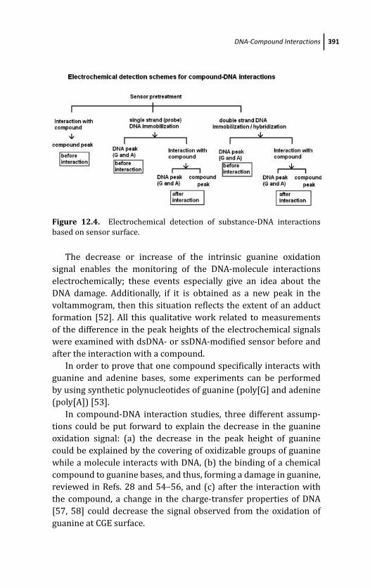
March 20, 2012 18:34 PSP Book - 9in x 6in 12-Ozsoz-c12
DNA-Compound Interactions 391
Figure 12.4. Electrochemical detection of substance-DNA interactions
based on sensor surface.
The decrease or increase of the intrinsic guanine oxidation
signal enables the monitoring of the DNA-molecule interactions
electrochemically; these events especially give an idea about the
DNA damage. Additionally, if it is obtained as a new peak in the
voltammogram, then this situation reflects the extent of an adduct
formation [52]. All this qualitative work related to measurements
of the difference in the peak heights of the electrochemical signals
were examined with dsDNA- or ssDNA-modified sensor before and
after the interaction with a compound.
In order to prove that one compound specifically interacts with
guanine and adenine bases, some experiments can be performed
by using synthetic polynucleotides of guanine (poly[G] and adenine
(poly[A]) [53].
In compound-DNA interaction studies, three different assump-
tions could be put forward to explain the decrease in the guanine
oxidation signal: (a) the decrease in the peak height of guanine
could be explained by the covering of oxidizable groups of guanine
while a molecule interacts with DNA, (b) the binding of a chemical
compound to guanine bases, and thus, forming a damage in guanine,
reviewed in Refs. 28 and 54–56, and (c) after the interaction with
the compound, a change in the charge-transfer properties of DNA
[57, 58] could decrease the signal observed from the oxidation of
guanine at CGE surface.
March 20, 2012 18:34 PSP Book - 9in x 6in 12-Ozsoz-c12
392 Electrochemical DNA Biosensors for Detection of Compound-DNA Interactions
12.5.2.2 Compound-based detection (indirect redoxindicator-based detection)
The compound-based electrochemical detection studies for
chemical-DNA interactions start with the identification of redox
potentials of related compounds by using cyclic voltammetry in
general. The redox peak potential of guanine (+1.0V) [9] is also
evaluated by obtaining compound peaks if both DNA and compound
signals don’t lie in the same peak position in the voltammogram.
Total evaluations are performed with the results of bare and DNA-
modified surfaces together based on both DNA and compound
signals.
In some promising applications about compound-DNA inter-
actions, these molecules can be found as a “DNA hybridization
indicator” because of their different binding behaviors to dsDNA
or ssDNA [59, 60]. This knowledge provides the development of
new drugs and DNA sensors which will further become microchip
devices. Indicator-based electrochemical DNA biosensors contains
electroactive compounds such as methylene blue (MB) [61],
ferrocenylnapthalene diimide [62], several metal complexes such
as cobalt phenanthroline [20], osmium, and ruthenium [63]. In
other applications, Kelley et al. [64] and Boon et al. [57] used
electroactive intercalators which noncovalently bound to DNA for
the detection of different kinds of single-base nucleotide changes.
Some redox-active DNA markers such as ferrocene [65], amino
and nitro-phenyl tags [66], tris-bipyridine complexes of osmium
or ruthenium were applied by Fojta et al. [67] for the detection
of SNPs (single nucleotide polymorphisms). Furthermore, carbon-
based transducers have also been used with several noncovalent or
covalent binding labels on DNA [2, 61, 68].
Panke et al. [69] performed a different approach related to a
competitive binding protocol for the determination of DNA single
base mismatches by using methylene blue in combination with
differential pulse voltammetry technique. Duwensee et al. [70]
reported a strategy for sequence-specific DNA detection by means
of a competitive hybridization assay with osmium tetroxide-labeled
signaling probes.
March 20, 2012 18:34 PSP Book - 9in x 6in 12-Ozsoz-c12
DNA-Compound Interactions 393
Marrazza et al. [71] investigated a electrochemical hybridization
indicator “daunomycin” for detecting Apo E polymorphisms in real
PCR. Wang et al. [72] performed the detection of interaction between
daunomycin and DNA in the solution phase and at the sensor sur-
face. Erdem and Ozsoz [60] was showed the other electrochemical
redox-active indicator drug “Epirubicin” which was used for the
detection of mismatched sequences. Hashimoto et al. [73] obtained
that the anodic signals of daunomycin and doxorubicin shifted to
more positive values after DNA immobilization onto basal plane
pyrolytic graphite transducer.
The changes monitored in the electroactive signals of DNA bases
indicate the behavior of compounds toward DNA [74, 75].
For the investigation of interaction mechanism of some com-
pounds as metal coordination complexes with DNA, Bard etal. [76] reported comprehensive electrochemical studies using
cobalt/ferrum phenanthroline or cobalt/ferrum bipyridine. In that
paper, they evaluated limiting shifts and binding constants of
mediator compounds by cyclic voltammetry in the absence and
presence of DNA in solution phase experiments. As a result of
their report, they found those forms (oxidized or reduced form) of
mediator compounds which bind to the DNA molecule with a high
affinity.
Carter et al. [77] also investigated cobalt phenanthroline and
DNA interactions in their previous paper which contained explana-
tions about the dependence of the redox behavior on the nature of
the ligands coordinated to the metal center.
Some other examples about drug-DNA interactions have been
seen in the literature. The antibiotic mitomycin C (MC) and its
interactions with DNA were investgated based on guanine oxidation
signal by Ozkan et al. [78]. Meric et al. [53] described a biosensor
for the detection of interaction between a compound synthesized
as an alkylating anticancer agent and DNA. Jelen et al. [79] found a
redox active bis-intercalator anticancer drug, Echinomycin, and they
showed its interactions with DNA. The intercalator “Adriamycin” and
its in situ interaction with DNA was reported by Brett et al. [80].
These types of interactions have been reviewed by Palecek and
Fojta [54, 55].
March 20, 2012 18:34 PSP Book - 9in x 6in 12-Ozsoz-c12
394 Electrochemical DNA Biosensors for Detection of Compound-DNA Interactions
12.6 Calculations About Compound-DNA Interactions
In order to investigate the interaction mechanism of a compound
with DNA, different approaches have been presented which can
be used in practical applications such as guanine signal-based
measurement, compound signal-based detection.
The change in the guanine peak is generally used for the
calculations of electrochemical DNA biosensors because guanine is
more easily oxidized than other DNA bases and it can be evaluated
as one of the key criteria for the voltammetric detection of DNA-
drug interactions. The decrease in the guanine signal is estimated
with interactions between compounds and DNA, the current ratio of
guanine (S%) is calculated according to the Bagni et al. [34] equation
which shown below:
S% = (Ss/Sb ) × 100
According to the equation, Ss is the signal ratio of the peak
height of guanine after the interaction with a sample compound,
and Sb is the magnitude of guanine signal after the interaction
with the buffer which is used for the preparation of the related
compound. The guanine oxidation signal obtained with differential
pulse voltammetry (DPV) in absence of a compound served as 100%.
After the interaction between a compound and DNA, if it is obtained
at S > 85% of value, the molecule is considered nontoxic, if it
is obtained that S% value is between 50 and 85, compound is
evaluated moderately toxic, and if the calculation of S% values are
obtained as S < 50%, compound is accepted as toxic.
In order to find an idea about interaction mechanism of a
compound with DNA, the other important value is “partition
coefficient” which was investigated by Millan and Mikkelsen [20]
in 1993. The partition coefficient value is calculated for DNA
biosensors using current signals obtained from probe modified,
hybrid modified, and bare electrodes according to the equation:
Partition coefficient = Compoundbound/Compoundfree
= |(ibound − ifree)/ ifree|Here ifree is the electrochemical peak height of a compound obtained
at bare electrode, and ibound is the oxidation peak current of a com-
March 20, 2012 18:34 PSP Book - 9in x 6in 12-Ozsoz-c12
Conclusions 395
pound obtained from probe(ssDNA)-modified or hybrid(dsDNA)-
modified electrodes after their interaction with DNA. After the
calculations, if it is seen that a higher value with ssDNA-modified
transducer is obtained than the one with dsDNA-modified electrode,
the related molecule is accepted to show a high affinity to single-
strand DNA structure. In other words, the compound partitions
more into the ssDNA microenvironment than the one of dsDNA as
a result of these calculations.
Carter et al. [76] showed important calculations by using
voltammetric methods for the detection of interaction (electrostatic
or intercalative) of metal complexes with calf thymus DNA. In that
report, binding constant (K n+) and binding region size(s) were
detected from voltammetric data, that is, shifts in potential and
changes in limiting current with the addition of DNA.
The shift in E1/2 value can be used to estimate the ratio of
equilibrium constants for the binding of the oxidized and reduced
forms of ions to DNA molecule. Similarly, for the detection of small
molecules and micelles interactions this value was used [81].
Considering the Nernstian electron-transfer rate for the
reversible redox reactions of the free and bound forms of com-
pounds and the corresponding equilibrium constants for binding of
each oxidation state to DNA yields, for a 1-e− redox process,
E o′b − E o′
f = 0.059 log(K red/K ox)
E o′f and E o′
b are the formal potentials of the oxidized and
reduced forms of a compound couple, in the free and bound forms,
respectively. K ox and K red are the corresponding binding constants
for the oxidized and reduced species to DNA.
As a result, according to limiting shift the ratio of K red/K ox is
calculated and which form of a compound binds to DNA strongly is
determined.
12.7 Conclusions
Electrochemical DNA biosensors (genosensors) developing for the
detection of compound-DNA interactions are very competitive
devices for the aim of detection time and cost, with the possibility
March 20, 2012 18:34 PSP Book - 9in x 6in 12-Ozsoz-c12
396 Electrochemical DNA Biosensors for Detection of Compound-DNA Interactions
of user-friendly analysis of interaction of various substances such
as carcinogens, mutagens, or drugs with DNA, according to the
requirements of point-of-care analysis.
The specific determination of interaction between DNA and
related molecules is of impotance in the design of the electrochem-
ical genosensors for application in diagnosis tests and in the design
of new drugs, especially for chemotherapy.
In this chapter, the usage of voltammetric techniques for
compound-DNA interactions were shown with detailed information
which contains some key ways to discover unknown molecule-DNA
interaction mechanisms as electrostatic interactions with the DNA
backbone, covalent or groove binding of the double strand of helix,
and intercalation of aromatic compounds between adjacent base
pairs.
When compared to other analysis methodologies such as surface
plasmon resonance (SPR), quartz crystal microbalance (QCM)
or impedance (EIS), voltammetry-based sensors provide short
response time, less-expensive analysis about immobilization of
molecules, and in many analyses they allow real-time measure-
ments.
References
1. T. Strachan and A. P. Read, Human Molecular Genetics 2, 2nd ed., John
Wiley & Sons, BIOS Scientific Publishers Ltd., 1–8 (1999).
2. G. Marrazza, I. Chianella, and M. Mascini, Disposable DNA electrochem-
ical sensor for hybridization detection, Biosens. Bioelectron. 14(1), 43–
51 (1999).
3. E. Palecek, Topics in Bioelectrochemistry and Bioenergetics, Vol. 5, John
Wiley, Chichester, 65–155 (1983).
4. E. Palecek, From polarography of DNA to microanalysis with nucleic
acid-modified electrodes, Electroanalysis 8(1), 7–14 (1996).
5. E. Palecek, Past, present and future of nucleic acids electrochemistry,
Talanta 56(5), 809–819 (2002).
6. E. Palecek, M. Fojta, F. Jelen, and V. Vetterl, The Encyclopedia ofElectrochemistry, Bioelectrochemistry, Vol. 9, Wiley-VCH, Weinheim,
365–429 (2002).
March 20, 2012 18:34 PSP Book - 9in x 6in 12-Ozsoz-c12
References 397
7. V. Vrabec, V. Vetterl, and O. Vrana, Experimental Techniques in Bioelectro-chemistry, Vol. 3, Birkhauser Verlag, Basel 287–359 (1996).
8. L. Trnkova, J. Friml, and O. Dracka, Elimination voltammetry of adenine
and cytosine mixtures, Bioelectrochemistry 54(2), 131–136 (2001).
9. D. O. Ariksoysal, H. Karadeniz, A. Erdem, A. Sengonul, A. A. Sayiner,
and M. Ozsoz, Label-free electrochemical hybridization genosensor for
the detection of hepatitis B virus genotype on the development of
lamivudine resistance, Analy. Chem. 77(15), 4908–4917 (2005).
10. M. Tomschik, F. Jelen, L. Havran, L. Trnkova, P. E. Nielsen, and E. Palecek,
Reduction and oxidation of peptide nucleic acid and DNA at mercury
and carbon electrodes, J. Electroanal. Chem. 476(1), 71–80 (1999).
11. J. Wang, S. Bollo, J. L. L. Paz, E. Sahlin, and B. Mukherjee, Ultratrace mea-
surements of nucleic acids by baseline-corrected adsorptive stripping
square-wave voltammetry, Anal. Chem. 71(9), 1910–1913 (1999).
12. J. Wang, X. H. Cai, J. Y. Wang, C. Jonsson, and E. Palecek, Trace
Measurements of RNA by potentiometric stripping analysis at carbon-
paste electrodes, Anal. Chem. 67(22), 4065–4070 (1995).
13. D. Ozkan-Ariksoysal, B. Tezcanli, B. Kosova, and M. Ozsoz, Design of
electrochemical biosensor systems for the detection of specific DNA
sequences in PCR-amplified nucleic acids related to the catechol-O-
methyltransferase val1 08/158Met polymorphism based on intrinsic
guanine signal, Analy. Chem. 80(3), 588–596 (2008).
14. E. Palecek and M. Fojta, Bioelectronics: From Theory to Applications,Wiley, 146 (2005).
15. F. Lucarelli, G. Marrazza, A. P. F. Turner, and M. Mascini, Carbon and
gold electrodes as electrochemical transducers for DNA hybridisation
sensors, Biosens. Bioelectron. 19(6), 515–530 (2004).
16. A. Erdem, M. I. Pividori, M. del Valle, and S. Alegret, Rigid carbon
composites: a new transducing material for label-free electrochemical
genosensing, J. Electroanal. Chem. 567(1), 29–37 (2004).
17. D. Ozkan, A. Erdem, P. Kara, K. Kerman, B. Meric, J. Hassmann,
and M. Ozsoz, Allele-specific genotype detection of factor V Leiden
mutation from polymerase chain reaction amplicons based on label-free
electrochemical genosensor, Anal. Chem. 74(23), 5931–5936 (2002).
18. A. Erdem, K. Kerman, B. Meric, U. S. Akarca, and M. Ozsoz, DNA
electrochemical biosensor for the detection of short DNA sequences
related to the hepatitis B virus, Electroanalysis 11(8), 586–588 (1999).
19. J. Wang, X. H. Cai, G. Rivas, H. Shiraishi, P. A. M. Farias, and N. Dontha, DNA
electrochemical biosensor for the detection of short DNA sequences
March 20, 2012 18:34 PSP Book - 9in x 6in 12-Ozsoz-c12
398 Electrochemical DNA Biosensors for Detection of Compound-DNA Interactions
related to the human immunodeficiency virus, Anal. Chem. 68(15),
2629–2634 (1996).
20. K. M. Millan and S. R. Mikkelsen, Sequence-selective biosensor for DNA-
based on electroactive hybridization indicators, Anal. Chem. 65(17),
2317–2323 (1993).
21. M. S. Yang, M. E. McGovern, and M. Thompson, Genosensor technology
and the detection of interfacial nucleic acid chemistry, Anal. Chim. Acta346(3), 259–275 (1997).
22. O. H. Laitinen, V. P. Hytonen, H. R. Nordlund, and M. S. Kulomaa,
Genetically engineered avidins and streptavidins, Cell. Mol. Life Sci.63(24), 2992–3017 (2006).
23. E. Palecek and F. Jelen, Electrochemistry of nucleic acids and develop-
ment of DNA sensors, Crit. Rev. Anal. Chem. 32(3), 261–270 (2002).
24. Y. K. Ye and H. X. Ju, DNA electrochemical behaviours, recognition
and sensing by combining with PCR technique, Sensors 3(6), 128–145
(2003).
25. T. G. Drummond, M. G.; Hill, and J. K. Barton, Electrochemical DNA
sensors, Nat. Biotech. 21(10), 1192–1199 (2003).
26. G. L. Eichhorn and Y. A. Shin, J. Am. Chem. Soc. 90, 7323 (1968).
27. S. Neidle, DNA Structure and Recognition, Oxford University Press
(1994).
28. A. Erdem and M. Ozsoz, Electrochemical DNA biosensors based on DNA-
drug interactions, Electroanalysis 14(14), 965–974 (2002).
29. D. Goodsell and R. E. Dicherson, J. Med. Chem. 29, 727 (1986).
30. D. Z. M. Coggan, I. S. Haworth, P. J. Bates, A. Robinson, and A. Rodger,
DNA binding of ruthenium tris(1,10-phenanthroline): Evidence for the
dependence of binding mode on metal complex concentration, Inorg.Chem. 38(20), 4486–4497 (1999).
31. R. Marrington, T. R. Dafforn, D. J. Halsall, and A. Rodger, Micro-volume
Couette flow sample orientation for absorbance and fluorescence linear
dichroism, Biophys. J. 87(3), 2002–2012 (2004).
32. K. M. Millan, A. Saraullo, and S. R. Mikkelsen, Voltammetric DNA biosen-
sor for cystic-fibrosis based on a modified carbon-paste electrode, Anal.Chem. 66(18), 2943–2948 (1994).
33. B. Rosenberg, L. VanCamp, and T. Krigas, Nature 205, 698 (1965).
34. G. Bagni, D. Osella, E. Sturchio, and M. Mascini, Deoxyribonucleic acid
(DNA) biosensors for environmental risk assessment and drug studies,
Anal. Chim. Acta 573, 81–89 (2006).
March 20, 2012 18:34 PSP Book - 9in x 6in 12-Ozsoz-c12
References 399
35. T. Boulikas and M. Vougiouka, Cisplatin and platinum drugs at the
molecular level (review), Oncol. Rep. 10(6), 1663–1682 (2003).
36. A. D. Richards and A. Rodger, Synthetic metallomolecules as agents
for the control of DNA structure, Chem. Soc. Rev. 36(3), 471–483
(2007).
37. A. Parkinson, M. Hawken, M. Hall, K. J. Sanders, and A. Rodger,
Amine induced Z-DNA in poly(dG-dC)center dot poly(dG-dC): Circular
dichroism and gel electrophoresis study, Phys. Chem. Chem. Phys. 2(23),
5469–5478 (2000).
38. W. I. P. Mainwaring, J. H. Parish, J. D. Pickering, and N. H. Mann,
Nucleic Acid Biochemistry and Molecular Biology, Blackwell Scientific
Publications, Oxford (1982).
39. L. S. Lerman, J. Mol. Biol. 3, 18 (1961).
40. K. Kerman, D. Ozkan, P. Kara, H. Karadeniz, Z. Ozkan, A. Erdem, F. Jelen,
and M.Ozsoz, Electrochemical detection of specific DNA sequences from
PCR amplicons on carbon and mercury electrodes using Meldola’s Blue
as an intercalator, Turk. J. Chem. 28, 523–533 (2004).
41. P. Kara, B. Meric, A. Zeytinoglu, and M. Ozsoz, Electrochemical DNA
biosensor for the detection and discrimination of herpes simplex Type
I and Type II viruses from PCR amplified real samples, Anal. Chim. Acta518(1–2), 69–76 (2004).
42. K. Kerman, Y. Matsubara, Y. Morita, Y. Takamura, and E. Tamiya,
Peptide nucleic acid modified magnetic beads for intercalator based
electrochemical detection of DNA hybridization, Sci. Technol. Adv. Mater.
5(3), 351–357 (2004).
43. N. Aladag, D. Ozkan-Ariksoysal, D. Gezen-Ak, S. Yilmazer, and M. Ozsoz,
An electrochemical DNA biosensor for the detection of the Apa I
polymorphism in the vitamin D receptor gene using Meldola’s blue as
a hybridization indicator, Electroanalysis 22(5), 590–598 (2010).
44. G. D. Reid, D. J. Whittaker, M. A. Day, D. A. Turton, V. Kayser, J. M. Kelly,
and G. S. Beddard, Femtosecond electron-transfer reactions in mono-
and polynucleotides and in DNA, J. Am. Chem. Soc. 124(19), 5518–5527
(2002).
45. A. Erdem, K. Kerman, B. Meric, U. S. Akarca, and M. Ozsoz, Novel
hybridization indicator methylene blue for the electrochemical detec-
tion of short DNA sequences related to the hepatitis B virus, Anal. Chim.Acta 422(2), 139–149 (2000).
46. W. R. Yang, M. Ozsoz, D. B. Hibbert, and J. J. Gooding, Evidence for the
direct interaction between methylene blue and guanine bases using
March 20, 2012 18:34 PSP Book - 9in x 6in 12-Ozsoz-c12
400 Electrochemical DNA Biosensors for Detection of Compound-DNA Interactions
DNA-modified carbon paste electrodes, Electroanalysis 14(18), 1299–
1302 (2002).
47. R. Rohs, H. Sklenar, R. Lavery, and B. Roder, Methylene blue binding to
DNA with alternating GC base sequence: A modeling study, J. Am. Chem.Soc. 122(12), 2860–2866 (2000).
48. M. Enescu, B. Levy, and V. Gheorghe, Molecular dynamics simulation
of methylene blue-guanine complex in water: The role of solvent in
stacking, J. Phys. Chem. B 104(5), 1073–1077 (2000).
49. S. O. Kelley, J. K. Barton, N. M. Jackson, and M. G. Hill, Electrochemistry of
methylene blue bound to a DNA-modified electrode, Bioconjugate Chem.1997, 8(1), 31–37.
50. A. Tani, A. J. Thomson, and J. N. Butt, Methylene blue as an electro-
chemical discriminator of single- and double-stranded oligonucleotides
immobilised on gold substrates, Analyst 126(10), 1756–1759 (2001).
51. J. A. Miller, Recent studies on the metabolic-activation of chemical
carcinogens, Cancer Res. 54(7), S1879–S1881 (1994).
52. K. Kerman, B. Meric, D. Ozkan, P. Kara, A. Erdem, and M. Ozsoz, Electro-
chemical DNA biosensor for the determination of benzo[a]pyrene-DNA
adducts, Anal. Chim. Acta 450(1–2), 45–52 (2001).
53. B. Meric, K. Kerman, D. Ozkan, P. Kara, A. Erdem, O. Kucukoglu, E. Erciyas,
and M. Ozsoz, Electrochemical biosensor for the interaction of DNA
with the alkylating agent 4,4-dihydroxy chalcone based on guanine and
adenine signals, J. Pharm. Biomed. Anal. 30(4), 1339–1346 (2002).
54. E. Palecek and M. Fojta, Detecting DNA hybridization and damage, Anal.Chem. 73(3), 74a–83a (2001).
55. M. Fojta, Electrochemical sensors for DNA interactions and damage.
Electroanalysis 14(21), 1449–1463 (2002).
56. J. Wang, Electrochemical nucleic acid biosensors, Anal. Chim. Acta469(1), 63–71 (2002).
57. E. M. Boon, D. M. Ceres, T. G. Drummond, M. G. Hill, and J. K. Barton,
Mutation detection by electrocatalysis at DNA-modified electrodes,
Nature Biotechnol. 18(10), 1096–1100 (2000).
58. E. L. S. Wong and J. J. Gooding, The electrochemical monitoring of the
perturbation of charge transfer through DNA by cisplatin, J. Am. Chem.Soc. 129(29), 8950–8951 (2007).
59. J. H. Chen, J. Zhang, L. Y. Huang, X. H. Lin, and G. N. Chen, Hybridization
biosensor using 2-nitroacridone as electrochemical indicator for detec-
tion of short DNA species of Chronic Myelogenous Leukemia, Biosens.Bioelect. 24(3), 349–355 (2008).
March 20, 2012 18:34 PSP Book - 9in x 6in 12-Ozsoz-c12
References 401
60. A. Erdem and M. Ozsoz, Interaction of the anticancer drug epirubicin
with DNA, Anal. Chim. Acta 437(1), 107–114 (2001).
61. D. Ozkan, A. Erdem, P. Kara, K. Kerman, J. J. Gooding, P. E. Nielsen, and M.
Ozsoz, Electrochemical detection of hybridization using peptide nucleic
acids and methylene blue on self-assembled alkanethiol monolayer
modified gold electrodes, Electrochem. Comm. 4(10), 796–802 (2002).
62. S. Takenaka, K. Yamashita, M. Takagi, Y. Uto, and H. Kondo, DNA sensing
on a DNA probe-modified electrode using ferrocenylnaphthalene
diimide as the electrochemically active ligand, Anal. Chem. 72(6), 1334–
1341 (2000).
63. A. B. Steel, T. M. Herne, and M. J. Tarlov, Electrochemical quantitation of
DNA immobilized on gold, Anal. Chem. 70(22), 4670–4677 (1998).
64. S. O. Kelley, E. M. Boon, J. K. Barton, N. M. Jackson, and M. G. Hill, Single-
base mismatch detection based on charge transduction through DNA,
Nucleic Acids Res. 27(24), 4830–4837 (1999).
65. P. Brazdilova, M. Vrabel, R. Pohl, H. Pivonkova, L. Havran, M. Hocek,
and M. Fojta, Ferrocenylethynyl derivatives of nucleoside triphosphates:
Synthesis, incorporation, electrochemistry, and bioanalytical applica-
tions, Chemistry 13(34), 9527–9533 (2007).
66. H. Cahova, L. Havran, P. Brazdilova, H. Pivonkova, R. Pohl, M. Fojta,
and M. Hocek, Aminophenyl- and nitrophenyl-labeled nucleoside
triphosphates: Synthesis, enzymatic incorporation, and electrochemical
detection, Angew. Chem., Int. Ed. 47(11), 2059–2062 (2008).
67. M. Vrabel, P. Horakova, H. Pivonkova, L. Kalachova, H. Cernocka, H.
Cahova, R. Pohl, P. Sebest, L. Havran, M. Hocek, and M. Fojta, Base-
modified DNA labeled by [Ru(bpy)(3)](2+) and [Os(bpy)(3)](2+)
Complexes: construction by polymerase incorporation of modified
nucleoside triphosphates, electrochemical and luminescent properties,
and applications, Chemistry 15(5), 1144–1154 (2009).
68. J. Labuda, M. Buckova, L. Heilerova, S. Silhar, and I. Stepanek, Evaluation
of the redox properties and anti/pro-oxidant effects of selected
flavonoids by means of a DNA-based electrochemical biosensor, Anal.Bioanal. Chem. 376(2), 168–173 (2003).
69. O. Panke, A. Kirbs, and F. Lisdat, Voltammetric detection of single base-
pair mismatches and quantification of label-free target ssDNA using
Biosens. Bioelectron. 22(11), 2656–2662 (2007).
70. H. Duwensee, M. Jacobsen, and G. U. Flechsig, Electrochemical compet-
itive hybridization assay for DNA detection using osmium tetroxide-
labelled signalling strands, Analyst 134(5), 899–903 (2009).
March 20, 2012 18:34 PSP Book - 9in x 6in 12-Ozsoz-c12
402 Electrochemical DNA Biosensors for Detection of Compound-DNA Interactions
71. G. Marrazza, G. Chiti, M. Mascini, and M. Anichini, Detection of human
apolipoprotein E genotypes by DNA electrochemical biosensor coupled
with PCR, Clinic. Chem. 46(1), 31–37 (2000).
72. J. Wang, M. Ozsoz, X. H. Cai, G. Rivas, H. Shiraishi, D. H. Grant,
M. Chicharro, J. Fernandes, and E. Palecek, Interactions of antitumor
drug daunomycin with DNA in solution and at the surface, Bioelec-trochem. Bioenerg. 45(1), 33–40 (1998).
73. K. Hashimoto, K. Ito, and Y. Ishimori, Novel DNA sensor for electrochem-
ical gene detection, Anal. Chim. Acta 286(2), 219–224 (1994).
74. V. Brabec, DNA sensor for the determination of antitumor platinum
compounds, Electrochim. Acta 45(18), 2929–2932 (2000).
75. F. Lucarelli, I. Palchetti, G. Marrazza, and M. Mascini, Electrochemical
DNA biosensor as a screening tool for the detection of toxicants in water
and wastewater samples, Talanta 56(5), 949–957 (2002).
76. M. T. Carter, M. Rodriguez, and A. J. Bard, Voltammetric studies of the
interaction of metal-chelates with DNA 2. tris-chelated complexes of
cobalt(III) and iron(II) with 1,10-phenanthroline and 2,2’-bipyridine,
J. Am. Chem. Soc. 111(24), 8901–8911 (1989).
77. M. T. Carter and A. J. Bard, Voltammetric studies of the interaction
of tris(1,10-Phenanthroline) cobalt(III) with DNA, J. Am. Chem. Soc.109(24), 7528–7530 (1987).
78. D. Ozkan, H. Karadeniz, A. Erdem, M. Mascini, and M. Ozsoz, Elec-
trochemical genosensor for Mitomycin C-DNA interaction based on
guanine signal, J. Pharm. Biomed. Anal. 35(4), 905–912 (2004).
79. F. Jelen, A. Erdem, and E. Palecek, Cyclic voltammetry of echinomycin
and its interaction with double-stranded and single-stranded DNA
adsorbed at the electrode, Bioelectrochemistry 55(1–2), 165–167
(2002).
80. A. M. Oliveira-Brett, M. Vivan, I. R. Fernandes, J. A. P. Piedade,
Electrochemical detection of in situ adriamycin oxidative damage to
DNA, Talanta 56(5), 959–970 (2002).
81. A. E. Kaifer and A. J. Bard, Micellar effects on the reductive electrochem-
istry of methylviologen, J. Phy. Chem. 89(22), 4876–4880 (1985).
March 19, 2012 15:47 PSP Book - 9in x 6in 13-Ozsoz-c13
Chapter 13
Electrochemical Nucleic Acid BiosensorsBased on Hybridization Detection forClinical Analysis
P. Kara, D. Ariksoysal, and M. OzsozDepartment of Analytical Chemistry, Faculty of Pharmacy, Ege University,35100, Bornova, Izmir, [email protected]
13.1 Introduction
Identification of nucleic acid sequences especially in biological
samples led to early diagnosis of many mutations, microbiological,
and inherited diseases [1]. The detection of specific base sequences
in human, viral, or bacterial DNA holds great importance in
diagnosis of several diseases. Detection of infectious and inherited
diseases at molecular levels provides reliable and early diagnosis.
Traditional diagnostic methods for clinical analysis based on
coupling of electrophoretic separations, radioisotope or fluorescent
labeling are toxic and time consuming. Due to these labor-intensive
methods these are not well suited for routine and rapid clinical
analysis [2]. Recently, there have been major advances in DNA
sequencing technologies [3]. Several methods including various
Electrochemical DNA BiosensorsEdited by Mehmet OzsozCopyright c© 2012 Pan Stanford Publishing Pte. Ltd.ISBN 978-981-4241-77-9 (Hardcover), 978-981-4303-98-9 (eBook)www.panstanford.com
March 19, 2012 15:47 PSP Book - 9in x 6in 13-Ozsoz-c13
404 Electrochemical Nucleic Acid Biosensors Based on Hybridization Detection
approaches have been available in genotyping processes such as
polymerase extension [4], oligonucleotide ligation [5], enzymatic
cleavage [6], and flap endonuclease discrimination [7].
An optimum detection method should be compact, highly
sensitive and selective, rapid, high throughput, and cost effective.
Many fast and sensitive methods have been designed to specify only
one or a few target sequences simultaneously. While thousands of
genotypes can be analyzed by using several methods, these devices
are still very expensive and time consuming [8].
Nucleic acid–based biosensors have gained a broad acceptance in
diagnostic testing, sequence specific analysis, DNA drug interactions,
detection of transgenic foods, and microbiological and inherited
diseases in clinical analysis. The growing number of nucleic acid–
based biosensors has stimulated a demand for automated, cost-
effective testing devices that also afford miniaturization of the test
platform [9].
Recently, some reports have indicated that electrochemical
techniques in nucleic acid biosensors are well suited for measuring
hybridization event [10].
Electrochemical DNA biosensor techniques for the detection of
microbiological and inherited diseases devoted to clinical analysis
are presented dealing with past and novel developments in this
chapter. For this purpose; particular emphasis will be given to the
most important approaches for electrochemical genosensing.
13.2 Biosensors
A biosensor is an analytical device that has a recognition capability
for biochemical reactions. It consists of a biological material incor-
porated into a recognition interface connected with a physicochem-
ical transducer [11]. The recognition interface is based on specific
biochemical reactions such as enzyme/cofactor, antigen/antibody,
cell/receptor, and nucleic acids. The physicochemical transducer
recognizes this reaction and converts it to quantitative or semi-
quantitative measurable signal [12]. The aim of the biosensor
techniques is monitoring the biological analytes for in vivo and in
March 19, 2012 15:47 PSP Book - 9in x 6in 13-Ozsoz-c13
Biosensors 405
vitro applications. Most popular biosensor transductions are optical
[13], piezoelectrical [14], and electrochemical [15] techniques.
The basic scheme of a biosensor device is based on a biochemical
recognition surface, a physicochemical transducer, and a data
analyse equipment. When performing an analysis, biological sam-
ples that specifically interact with its substrates on the surface are
detected by the recognition surface. The results of the interaction
should form changes which can be physical or chemical. After
recognition, the detection signals are converted to another signal by
the transducer that can be analyzed easily. The transformed signal is
amplified and processed for user analysis.
The first biosensor was based on an enzyme electrode and
developed for glucose analysis in 1962 [16]. Then many researches
have focused on biosensing systems. This is mostly due to the
biosensor’s high selectivity and sensitivity [17]. In 1975, Divis
proposed microorganism electrode for determining the alcohol level
in a solution [18]. Also, same year the first glucose biosensor was
produced commercially by Yellow Springs Instruments.
13.2.1 Nucleic Acid Hybridization Biosensors
Nucleic acid is a biosensor which integrates nucleic acid hybridiza-
tion recognition with a signal transducer. Figure 13.1 is a schematic
representation of a nucleic acid biosensor.
The nucleic acid recognition part selectively detects a specific
gene sequence of DNA. A DNA hybridization biosensor uses a DNA
strand of known sequence as a probe of a target DNA sample.
In the last decade there has been a considerable interest in DNA
biosensors due to its significant analytical properties. The most
popular application of DNA biosensors is based on nucleic acid
hybridization detection of specific DNA sequences [19].
Such biosensors have many potential applications — for exam-
ple, identification of genes that are implicated in inherited diseases,
single nucleotide polymorphisms (SNP), and some mutations that
play a major role in causing diseases [20–21], identification of
pathogenic microorganisms which are responsible for infectious dis-
eases [22–23], transgenic organisms for food quality [24], detection
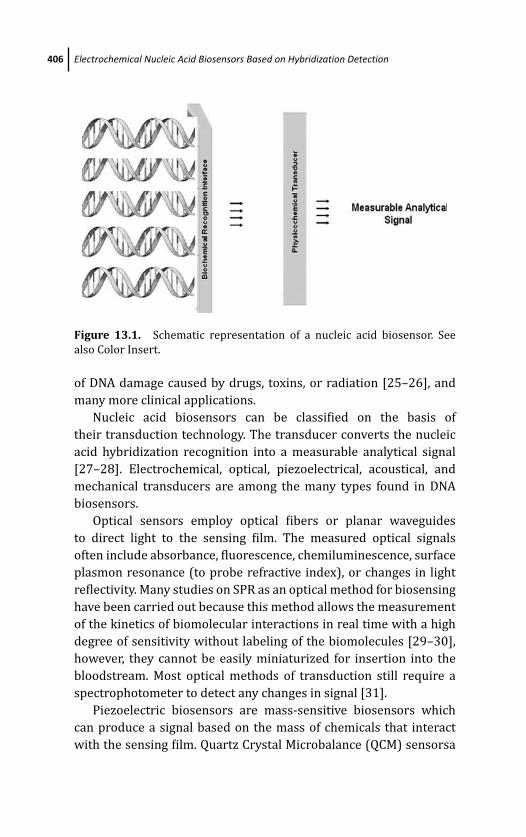
March 19, 2012 15:47 PSP Book - 9in x 6in 13-Ozsoz-c13
406 Electrochemical Nucleic Acid Biosensors Based on Hybridization Detection
Figure 13.1. Schematic representation of a nucleic acid biosensor. See
also Color Insert.
of DNA damage caused by drugs, toxins, or radiation [25–26], and
many more clinical applications.
Nucleic acid biosensors can be classified on the basis of
their transduction technology. The transducer converts the nucleic
acid hybridization recognition into a measurable analytical signal
[27–28]. Electrochemical, optical, piezoelectrical, acoustical, and
mechanical transducers are among the many types found in DNA
biosensors.
Optical sensors employ optical fibers or planar waveguides
to direct light to the sensing film. The measured optical signals
often include absorbance, fluorescence, chemiluminescence, surface
plasmon resonance (to probe refractive index), or changes in light
reflectivity. Many studies on SPR as an optical method for biosensing
have been carried out because this method allows the measurement
of the kinetics of biomolecular interactions in real time with a high
degree of sensitivity without labeling of the biomolecules [29–30],
however, they cannot be easily miniaturized for insertion into the
bloodstream. Most optical methods of transduction still require a
spectrophotometer to detect any changes in signal [31].
Piezoelectric biosensors are mass-sensitive biosensors which
can produce a signal based on the mass of chemicals that interact
with the sensing film. Quartz Crystal Microbalance (QCM) sensorsa

March 19, 2012 15:47 PSP Book - 9in x 6in 13-Ozsoz-c13
Electrochemical Nucleic Acid Biosensors 407
re piezoelectrical based sensors that are operated by applying an
oscillating voltage at the resonant frequency of the crystal, and
measuring the change in resonant frequency when the target analyte
interacts with the sensing surface [32]. The QCM method has
been adopted by several groups to detect the DNA hybridization
reaction because of its great sensitivity as a mass sensor capable of
measuring subnanogram mass changes [33–34].
Electrochemical biosensors measure the electrochemical
changes that occur when biochemical element interacts with a
sensing surface of the detecting electrode. The electrical changes
can be based on a change in the measured voltage between the
electrodes (potentiometric), a change in the measured current at a
given applied voltage (amperometric), or a change in the ability of
the sensing material to transport charge (conductometric) [35].
13.3 Electrochemical Nucleic Acid Biosensors
Electrochemical nucleic acid biosensors are based on electro-
chemical transduction of the hybridization event and show great
promise for detection of specific gene sequences related to inherited
and infectious diseases. Electrochemical detection of specific DNA
sequences has an advantage in reducing the size of the total
detection system [36]. The advantages of electrochemical nucleic
acid biosensors include potential of miniaturization, short response
time, ease of use, low cost, and compatibility with microfabrication
techniques [37].
The aim of electrochemical genosensing techniques is to design
DNA systems allowing early diagnosis of microorganisms and poly-
morphisms in clinical analysis. For this purpose several techniques
have been investigated based on recognition of DNA hybridization,
by using electroactive labels, dye molecules, nanoparticles, or label-
free methods.
Electrochemical DNA biosensors are divided into two main
groups:
1. Label-based DNA hybridization detection method
2. Label-free DNA hybridization detection method
March 19, 2012 15:47 PSP Book - 9in x 6in 13-Ozsoz-c13
408 Electrochemical Nucleic Acid Biosensors Based on Hybridization Detection
13.3.1 Label-Based Electrochemical Nucleic AcidBiosensors
Label-based electrochemical nucleic acid hybridization biosensors
work on the principle of the following groups:
1. Using redox active hybridization indicator which has an affinity
for ss or ds DNA
2. Using labeled signaling probes or labeled target DNA
13.3.1.1 Electrochemical genosensing by using hybridizationindicator
This approach is based on the electrochemical response of a redox
active label changes upon DNA hybridization, when the hybridiza-
tion process occurs due to change of the indicator concentration at
the electrode surface [38]. These redox active labels can be called as
“hybridization indicators” and have high affinity for either ssDNA or
dsDNA to transduce hybridization.
Hybridization indicators have various interaction properties of
dsDNA and ssDNA. Some metal complexes or dyes are intercalator
molecules which interact with hydrogen bonds of dsDNA [39], and
some indicators have selective binding processes onto DNA bases
such as guanine [40].
Intercalator hybridization labels are complex molecules that
have a planar aromatic group. Several methods for indicator-based
electrochemical sequence specific to DNA detection have been
reported. Wang et al. [41] described the hybridization detection
of short DNA sequences related to HIV virus genome due to the
chronopotentiometric transduction of Co(phen) as an hybridization
label. Electrochemiluminescense assays have also been reported by
Carter et al. [42] for specific DNA sequence detection.
Early studies on electrochemical nucleic acid biosensors were
based on electrochemical transduction of redox labels (indicators)
that have significant different behaviors between dsDNA and ssDNA.
These intercalator molecules have higher binding affinity to dsDNA
than ssDNA. Mikkelsen and coworkers investigated this approach
by using Co(phen) as a hybridization indicator. The intercalator
molecule was accumulated at ss and dsDNA at covalently attached
March 19, 2012 15:47 PSP Book - 9in x 6in 13-Ozsoz-c13
Electrochemical Nucleic Acid Biosensors 409
on to glassy carbon electrode surface [43]. Millan, also used
Co(phen) and osminum complexes as hybridization indicator to
detect hybridization. Short oligonucleotides related to cystic fibrosis
diseases were used as probe and target sequences [10]. Unmodified
probe sequence was immobilized onto carbon paste electrode (CPE)
and voltammetric transduction of metal intercalators was moni-
tored after hybridization occurred. Same year Millan’s group studied
on covalently attachment scheme. Oligonucleotides including Poly A,
Poly T, Poly C, and Poly G were used as model case. Carbodiimide
chemistry was first used onto glassy carbon electrode (GCE) surface
for covalently bounding of DNA [2].
This intercalator molecule has been investigated by many
workers, such as Mascini [44–45], Wang [46], and our group [38–
39] in detailed. In 1999, J. Barton’s group first worked on single–base
mismatch detection [19]. Thiol-modified oligonucleotide sequences
were attached on to gold electrode surface and hybridization
occurred with both full-match and mismatch target sequences.
The cyclic voltammetric transductions of intercalator molecules
including ruthenium complexes were monitored.
Mascini and coworkers were focused on detection of real sam-
ples, and they used PCR products related to human Apolipoprotein
E genotypes in 2000 [47]. Graphite screen-printed electrodes
were firstly used for clinical detection as sensor surface. Probe
sequences were adsorbed at SPE and hybridization was determined
by using daunomycin as indicator. Kobayashi et al. [48] investigated
a microelectrode array for simultaneous and multiple analysis. They
designed a sensor which had 32 arrays, and therefore it was possible
to work with several hybridization detection events at the same
time. Hybridization and mismatch detection was performed by using
lineer sweep voltammetric transduction of a commercial redox
active dye molecule as an intercalator. Yang et al. [49] developed
a genosensor for detection of PCR products by using 7-deaza
analogues of guanine and adenine. Cyclic voltammetry was used for
transduction of ruthenium complexes for the detection of E. coli PCR
product. Barton’s group used Rhodium derivates as intercalating
agent for rapid mismatch detection [50].
Our group is also focused on the detection of clinical analysis
based on intercalator molecules and on voltammetric transduction
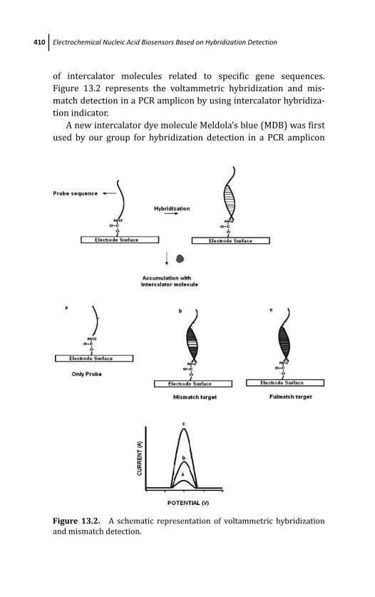
March 19, 2012 15:47 PSP Book - 9in x 6in 13-Ozsoz-c13
410 Electrochemical Nucleic Acid Biosensors Based on Hybridization Detection
of intercalator molecules related to specific gene sequences.
Figure 13.2 represents the voltammetric hybridization and mis-
match detection in a PCR amplicon by using intercalator hybridiza-
tion indicator.
A new intercalator dye molecule Meldola’s blue (MDB) was first
used by our group for hybridization detection in a PCR amplicon
Figure 13.2. A schematic representation of voltammetric hybridization
and mismatch detection.
March 19, 2012 15:47 PSP Book - 9in x 6in 13-Ozsoz-c13
Electrochemical Nucleic Acid Biosensors 411
[51]. A PCR sequence was used related to Hepatitis B (HBV) virus
genome. Optimization of hybridization detection was performed
with 17-mer short oligonucleotides. Carbon paste electrodes (CPE)
and hanging mercury drop electrodes (HMDE) were used as
sensor surface, CV and DPV transduction of MDB accumulated
after hybridization between 23-mer capture probe and HBV–PCR
amplicon was monitored for the detection. By using MDB indicator,
Herpes simplex (HSV) virus genome detection and discrimination
of HSV type I and type II viruses were performed in PCR amplicon
[52]. HSV type I and type II have very similar pathogenesis
mechanisms and have a homogeneous genome sequence. Two
types of PCR products related to type I and II which had 12
base differences in 179 base long amplicon were used as target
genomes. 22-mer capture probes related to type I and II had four
base differences between each other, were attached onto disposable
graphite electrode surfaces and hybridization occurred with both
types of PCR amplicons. The detection and the discrimination of
genotyping were accomplished by DPV transduction of accumulated
MDB. Consequently four base differences were detected by using
long PCR amplicon devoted to clinical analysis.
One base mismatch detections in real samples based on MDB
indicator were also performed in our following researches. In 2007,
we developed a genosensor for detection of toll-like receptor 2 (TLR
-2) gene polymorphisms [53]. In this study, one base mismatch
detection was performed in a 267 base long PCR product. Two types
of capture probes were used representing wild-type and mutant-
type genomes. DPV reduction signals of MDB were monitored after
hybridization with denatured amplicon at PGE surfaces. Heterozy-
gous and homozygous discrimination was also performed by using
two types of capture probes. Biosensor selectivity was achieved with
HBV non-complementary (NC) amplicon. Consequently an allele
specific genosensor was developed for SNP detection in this study.
Another polymorphism detection related to Apa I vitamin D receptor
gene was also performed in 2010 [54]. DPV signals of accumulated
MDB indicated hybridization and mismatch detection in 247-mer
PCR sequence.
Some hybridization indicators have chemical affinity to DNA
bases. Our group used another dye molecule, methylene blue
March 19, 2012 15:47 PSP Book - 9in x 6in 13-Ozsoz-c13
412 Electrochemical Nucleic Acid Biosensors Based on Hybridization Detection
(MB) as hybridization indicator in many researches. MB is an
aromatic heterocycle; although MB is an organic dye molecule and
an intercalating agent, it has a higher affinity to guanine bases
[55]. Enescu et al. [56] investigated the conformation of MB–
guanine complex by molecular dynamics simulation. The position
and orientation of MB–guanine complexes were found to be in three
modes: T-shaped, non-stacked and face to face. Due to this affinity,
we used MB as a hybridization indicator in several works.
Early studies with MB were performed by Barton [57] as
intercalator molecule. In 2000, our group used MB for the first time
as a hybridization indicator which has a strong affinity to guanine
[58]. In this study, 21-mer oligonucletotides related to Hepatitis
B virus (HBV) were immobilized onto CPE and hybridization was
detected after MB accumulation. Voltammetric transduction of MB
reduction was monitored. The comparison of indicator behaviors
between intecalator molecule ruthenium complex and MB was
performed in 2001 [59]. Calf-thymus dsDNA and ssDNA were
immobilized onto CPE electrostatically. CV and DPV transduction of
hybridization indicators were monitored after accumulation.
Figure 13.3 represents the voltammetric detection of hybridiza-
tion in the presence of MB hybridization indicator. Due to strong MB
affinity, voltammetric peak of MB after accumulation with (a) ssDNA
is significantly higher to (b) bare electrode, and (c) sDNA.
The effect of ionic strength onto MB accumulation behavior
was also studied by our group [60]. Chronocoulometric and
voltammetric parameters for MB on binding to DNA at CPE were
monitored. It was found that 10 mM ionic strength is the critical salt
concentration. MB interacts to guanine electrostatically up to 10 mM
NaCl, in the presence of higher concentrations of 10 mM of NaCl, MB
intercalates to hydrogen bounds of dsDNA.
Hybridization and one-base mismatch detection was performed
by using self-assembled monolayer (SAM) on gold electrodes
in the presence of MB indicator first time [61]. 14-mer short
oligonucleotides were immobilized onto Au electrode surface by
using alkanethiol monolayer coupling at surface. Mercaptopropionic
acid (MPA) was used for monolayer production. Voltammetric
reduction signal of MB was monitored for hybridization and
mismatch detection.
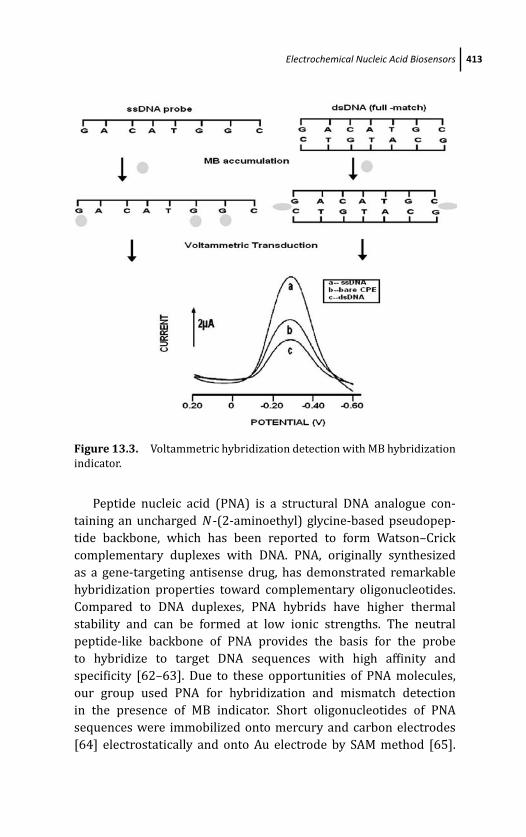
March 19, 2012 15:47 PSP Book - 9in x 6in 13-Ozsoz-c13
Electrochemical Nucleic Acid Biosensors 413
Figure 13.3. Voltammetric hybridization detection with MB hybridization
indicator.
Peptide nucleic acid (PNA) is a structural DNA analogue con-
taining an uncharged N -(2-aminoethyl) glycine-based pseudopep-
tide backbone, which has been reported to form Watson–Crick
complementary duplexes with DNA. PNA, originally synthesized
as a gene-targeting antisense drug, has demonstrated remarkable
hybridization properties toward complementary oligonucleotides.
Compared to DNA duplexes, PNA hybrids have higher thermal
stability and can be formed at low ionic strengths. The neutral
peptide-like backbone of PNA provides the basis for the probe
to hybridize to target DNA sequences with high affinity and
specificity [62–63]. Due to these opportunities of PNA molecules,
our group used PNA for hybridization and mismatch detection
in the presence of MB indicator. Short oligonucleotides of PNA
sequences were immobilized onto mercury and carbon electrodes
[64] electrostatically and onto Au electrode by SAM method [65].
March 19, 2012 15:47 PSP Book - 9in x 6in 13-Ozsoz-c13
414 Electrochemical Nucleic Acid Biosensors Based on Hybridization Detection
Consequently, mismatch detection was accomplished by voltammet-
ric transduction of MB accumulation.
The application of clinical analyses from real samples was
determined with HBV detection. For this purpose; we developed
a genosensor for clinical analysis of HBV based on MB indicator
[66]. In this study, real samples were used first time for medicinal
analyses. 24-mer capture probe related to HBV genome were
immobilized onto CPE electrostatically, the hybridiziation with
PCR amplicon and accumulation of MB was applied. Hybridization
detection was accomplished by monitoring the DPV reduction
signals of MB.
13.3.1.2 Electrochemical genosensing with labeled signalingprobe or labeled target DNA
Another approach to electrochemical biosensing of microbiological
and inherited diseases is to use labels attached onto capture probe
or target sequences. If a redox active molecule such as ferrocene has
been attached to probe sequence, the electron transfer of double-
stranded DNA has been insensitive due to the distance from the
electrode surface [67]. Ferrocene (Fc) and its derivates are attractive
redox active chemicals because of their stability [68]. Yu et al. [69]
prepared ferrocene-labeled oligonucleotides that were conjugated
with uridine. With the same technique, Yu [70] performed an
SNP detection based on DNA/RNA hybrids. Xu et al. [71] used
ferrocenecarboxaldehyde (FCA)-modified ssDNA probes bounded
at chitosan-modified electrode surfaces. Chitosan-modified graphite
surfaces provided a strong binding of probe sequence at the
surface, and hybridization detection was accomplished with DPV
transduction of FCA. 5’-FC–modified hairpin DNA probe was used
for sequence specific detection. Genosensing was performed by
transduction of AC voltammetry and differences in melting points
between FC-modified hybrid and unmodified target sequences [72].
The biotin–avidin system is used in a variety of biotech-
nological and diagnostic applications. It involves a chemical or
genetic (the bio-tag biotinylation) biotinylation step. Mascini used
biotinylated oligonucleotides for electrochemical genosensing [73].
Thiol-tethered capture probe was immobilized onto Au-SPE and

March 19, 2012 15:47 PSP Book - 9in x 6in 13-Ozsoz-c13
Electrochemical Nucleic Acid Biosensors 415
hybridization occurred with target sequence. Biotinylated signal-
ing probe was added onto PCR target and accumulation with
streptavidine–alkaline phosphatese conjugate was monitored by
impedance spectrometry. Based on this method, we used alpha
napthol as indicator [74]. Capture probe was modified onto
graphite surface and hybridization occurred with biotinylated target
sequence. Avidine–alkalinephosphatase complex was coupled with
hybrid and napthyl phosphate was added onto the surface. The
DPV reduction signal of napthol was used as an indicator. For
detection of different bacterial food contaminations [75], Legionella
pneumophila with hairpin DNA probe [76] was performed by using
this system.
13.3.2 Label-Free Electrochemical Genosensing
The main disadvantage of electrochemical nucleic acid biosensors
discussed above is requirement for an indicator to transduce
hybridization. Many scientists have focused on developing label-free
methods for directly monitoring the hybridization event. Wang and
coworkers [77] studied the oxidation signal of guanine base at about
1.00 V. Wang and coworkers [78] have determined that guanine is
the most electroactive base when compared with cytosine, timine,
and adenine. In this study, Wang used a pencil-based renewable
electrode for sensor surface. Former solution based electrochemical
reports have shown that the electron transfer from the uncatalyzed
guanine bases was slow at most electrode surfaces, however,
guanine oxidation could well be observed by using voltammetric
techniques when the guanine was adsorbed onto the CPE [79].
Tomschik et al. [80] observed the oxidation signals of guanine
and adenine at low concentrations of DNA and PNA by applying
chronopotentiometry and voltammetry with a suitable baseline
correction system at pyrolytic graphite electrode (PGE). By using
carbon nanotubes, Wang enhanced the surface area for label-free
detection of hybridization [81]. Prado et al. [82] used boron-doped
diamond electrodes for sensing surface. They monitored guanine
oxidation in ssDNA and dsDNA by cyclic voltammetry.
Label-free genosensing techniques have a great importance for
sequence specific detections in pharmaceutical and environmental
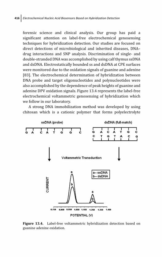
March 19, 2012 15:47 PSP Book - 9in x 6in 13-Ozsoz-c13
416 Electrochemical Nucleic Acid Biosensors Based on Hybridization Detection
forensic science and clinical analysis. Our group has paid a
significant attention on label-free electrochemical genosensing
techniques for hybridization detection. Our studies are focused on
direct detections of microbiological and inherited diseases, DNA–
drug interactions and SNP analysis. Discrimination of single- and
double-stranded DNA was accomplished by using calf thymus ssDNA
and dsDNA. Electrostatically bounded ss and dsDNA at CPE surfaces
were monitored due to the oxidation signals of guanine and adenine
[83]. The electrochemical determination of hybridization between
DNA probe and target oligonucleotides and polynucleotides were
also accomplished by the dependence of peak heights of guanine and
adenine DPV oxidation signals. Figure 13.4 represents the label-free
electrochemical voltammetric genosensing of hybridization which
we follow in our laboratory.
A strong DNA immobilization method was developed by using
chitosan which is a cationic polymer that forms polyelectrolyte
Figure 13.4. Label-free voltammetric hybridization detection based on
guanine adenine oxidation.
March 19, 2012 15:47 PSP Book - 9in x 6in 13-Ozsoz-c13
Electrochemical Nucleic Acid Biosensors 417
complexes with DNA. Chitosan-modified CPE (ChiCPE) surfaces
were used as a sensing area for direct detection of hybridization in
this study [84]. Calf-thymus ss and dsDNA were immobilized onto
ChiCPE surafces and hybridization between PNA oligonucleotides
was determined by transduction of guanine oxidation. Thereby, a
cost-effective, rapid and direct genosensing method was developed
that provided highly strong DNA immoblization. A label-free SNP
detection was also performed in our laboratory by using PNA
oligonucleotides [85].
The detection of PNA–DNA and DNA–DNA hybridizations were
accomplished based on the oxidation signal of guanine by using
DPV at CPE. It was observed that PNA–DNA hybrids have significant
peak height differences when compared with DNA–DNA hybrids. In
addition, PNA probes have a weaker affinity to mismatch targets,
so detection of point mutation was performed based on guanine
oxidation signals.
Sequence-specific bioelectronic detection of PCR amplicons were
performed with unpurified PCR samples by Lai et al. [86]. GyrB
genes of Salmonella typhimurium were produced in PCR reaction
and detection was performed by applying AC voltammetry. Manalis’
group investigated a label-free microelectronic PCR quantification
[87]. A field-effect microelectronic sensor was developed which was
capable of quanification of DNA during PCR reaction at polylysine
covered surfaces.
Wang et al. [88] described an indicator-free electrochemical DNA
biosensor protocol, which involves the immobilization of inosine-
substituted (guanine-free) probe onto CPE and the detection of
hybrid formation was performed by using the appearance of the
guanine oxidation signal of the target in connection with chronopo-
tentiometric stripping analysis (PSA). Napier et al. [89] also used
inosine substituted probes, in the presence of ruthenium complexes
as hybridization indicator. Macsini [90] has developed an inosine-
based label-free genosensor for identification of mammalian species
by using bovine and sheep PCR amplicons. Guanine-free capture
probes were immobilized onto screen-printed carbon electrodes
(SPE), hybridization between positive real samples of porc, bovine
and sheep sequences were monitored by DPV oxidation signals
of guanine. Kerman et al. [91] monitored guanine oxidation at
March 19, 2012 15:47 PSP Book - 9in x 6in 13-Ozsoz-c13
418 Electrochemical Nucleic Acid Biosensors Based on Hybridization Detection
about 0.73 V with square wave voltammetry (SWV) at l-cysteine
monolayer modified Au surfaces. 6-mer thymine-tag of the capture
probe was hybridized with the adenine probe, thus left the rest of
the oligonucleotide available for hybridization with the target.
The use of inosine-substituted probes and the appearance of
a guanine signal upon hybridization with the target opened a
new field in electrochemical research. We performed alle-specific
polymorphism detection in real samples by using inosine-modified
probe sequences, called yes/no system. Two capture probes related
to wild-type and mutant-type genoms were immobilized onto elec-
trode surface and hybridizations occured with denatured heterozy-
gous or homozygous amplicons. Favtor V Leiden and Achondropla-
sia G 380R point mutations were performed by this technology [92–
93]. It was observed that homozygous amplicons had only one signal
of guanine with their complementary strands, but on the other
hand, heterozygous amplicons had guanine signals with both probe
sequences [94]. Consequently, by using two different probes related
to both wild-type and mutant genomes, we could achieve rapid and
allele-specific detection. Figure 13.5 is the schematic representation
of voltametric allele-specific genosensing method based on yes/no
system. This method was able to detect down to 51.14 fmol mL1
target DNA. Similiar methods have been developed for the detection
of interleukin-2 DNA [95], Val108/158Met SNP in COMT gene
[96].
Optimizations of hybridization kinetics and washing conditions
including ionic strengths are the key points for effective detection
of microbiological and inherited diseases. Detection of optimum
probe sequence relative position in a long amplicon based on yes/no
system was studied [97]. 18-mer inosine-modified three capture
probes were chosen from several parts of HBV genome amplicon.
Two sequences were 5 base distance from primers, the 3rd sequence
was in the middle of the amplicon. The probes were guanine-free
besides including five cytosines in each sequence thus called as co-
equal captures. Capture probes were immobilized onto electrode
surfaces via carbodiimide chemistry. After hybridization occured;
optimum probe sequence position was identified by using the
differences between the responses of guanine oxidation signals. It
was observed that probe sequences chosen from the beginning and

March 19, 2012 15:47 PSP Book - 9in x 6in 13-Ozsoz-c13
Electrochemical Nucleic Acid Biosensors 419
Figure 13.5. Schematic illustration of electrochemical label-free allele-
specific genosensing method.
end part of the amplicon (close to primers) caused duplex formation
at the posterior of the long sequence, however, the probe chosen in
the middle section of the amplicon prevent the duplex formation
and stabilize the amplicon sequence for hybridization and provide
an optimum diagnosis.
Direct bioelectronic detection of multiple point mutations in
Mycobacterium tuberculosis amplicons related to rifampin drug
resistance was perfomed [98]. In recent studies, it was found that
95% of RIF-resistant bacteria strains possess mutations within
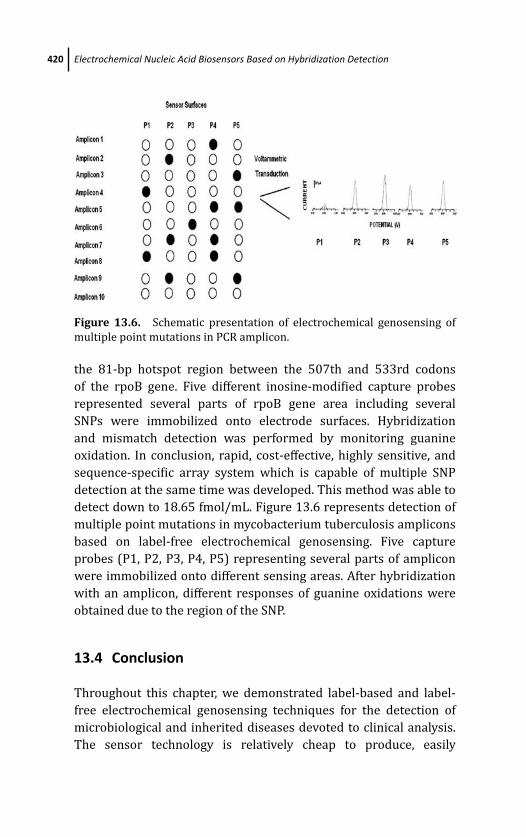
March 19, 2012 15:47 PSP Book - 9in x 6in 13-Ozsoz-c13
420 Electrochemical Nucleic Acid Biosensors Based on Hybridization Detection
Figure 13.6. Schematic presentation of electrochemical genosensing of
multiple point mutations in PCR amplicon.
the 81-bp hotspot region between the 507th and 533rd codons
of the rpoB gene. Five different inosine-modified capture probes
represented several parts of rpoB gene area including several
SNPs were immobilized onto electrode surfaces. Hybridization
and mismatch detection was performed by monitoring guanine
oxidation. In conclusion, rapid, cost-effective, highly sensitive, and
sequence-specific array system which is capable of multiple SNP
detection at the same time was developed. This method was able to
detect down to 18.65 fmol/mL. Figure 13.6 represents detection of
multiple point mutations in mycobacterium tuberculosis amplicons
based on label-free electrochemical genosensing. Five capture
probes (P1, P2, P3, P4, P5) representing several parts of amplicon
were immobilized onto different sensing areas. After hybridization
with an amplicon, different responses of guanine oxidations were
obtained due to the region of the SNP.
13.4 Conclusion
Throughout this chapter, we demonstrated label-based and label-
free electrochemical genosensing techniques for the detection of
microbiological and inherited diseases devoted to clinical analysis.
The sensor technology is relatively cheap to produce, easily
March 19, 2012 15:47 PSP Book - 9in x 6in 13-Ozsoz-c13
References 421
stabilized, and voltammetric technique is stable. When compared
with conventional methods, it can be observed that electrochemical
techniques are also capable of sequence specificity and allele
specificity, time-consuming, and highly sensitive. Further research-
based mutation detection methods are under progress in our
laboratory.
References
1. G. H. Keller and M. N. Manak, DNA Probes, Stocton Press, New York 18(1989).
2. K. M. Millan and S. R. Mikkelsen, Anal. Chem. 65, 2317–2323 (1993).
3. P.D’Orazio, Clin. Chim. Acta 334, 41–69 (2003).
4. E. Basset, A. Vaisman, J. M. Havener, C. Masutani, F. Hanaoka, and S. G.
Chaney, Biochemistry, 42, 14197–14206 (2003).
5. R. Bordoni, B. Castiglioni, A. Mezzelani, E. Rizzi, A. Froscini,
C. Consolandi, L. R. Bernardi, C. Battaglia, and G. De Bellis, Clin. Chem.49, 1537–1540 (2003).
6. A. Trost, B. Graf, J. Eucker, O. Sezer, K. Possinger, U. B. Gobel, and T. Adam,
J. Microbiol. Methods 56, 201–211 (2004).
7. C. A. Mein, B. J. Barratt, M. G. Dunn, T. Siegmund, A. N. Smith, L. Esposito,
S. Nutland, H. E. Stevens, A. J. Wilson, M. S. Phillips, N. Jarvis, S. Law,
M. de Arruda, and J. A. Todd, Genome Res. 10, 330–343 (2000).
8. K. Meyer, A. Frediksen, and P. M. Ueland, Clin. Chem. 50, 391–402 (2004).
9. R. M. Umek, S. W. Lin, J. Vielmetter, R. H. Terbrueggen, B. Irvin, C. J. Yu,
et al., J. Mol. Diag. 3, 74–84 (2001).
10. K. M. Millan, A. Saraullo, and S. Mikkelsen, Anal. Chem. 66, 2943–2948
(1994).
11. A. D. McNaughty and A. Wilkinson, Compendium of Chemical Terminol-ogy, 2nd ed., Blackwell Science (1997).
12. T. M. Herne and M. Tarlov, J. Am. Chem. Society 119, 8916–8920 (1997).
13. E. L. S. Wong and J. J. Gooding, Anal. Chem. 75, 3845–3852 (2003).
14. P. C. Pandey and H. H. Weetall, Anal. Chem. 66, 1236–1241 (1994).
15. A. J. Downard, Electroanalysis 12, 1085–1096 (2000).
16. L. C. Clark and C. Lyons, Annals of New York Academic Sciences 102, 29–
45 (1962).
March 19, 2012 15:47 PSP Book - 9in x 6in 13-Ozsoz-c13
422 Electrochemical Nucleic Acid Biosensors Based on Hybridization Detection
17. A. F. Collings and F. Caruso, Reports on Progress in Physics 60, 1397–1445
(1997).
18. C. Divis, Annals of Microbiology 126A, 175–186 (1975).
19. S. O. Kelley, E. M. Boon, J. K. Barton, N. M. Jackson, and M. G. Hill, NucleicAcid Res. 27, 4830–4837 (1999).
20. F. Lucarelli, G. Marazza, A. P. F. Turner, and M. Mascini, Biosens.Bioelectron. 19, 515–530 (2004).
21. H. X. Ju and H. Zao, Frontiers in Bioscience 10, 37–46 (2005).
22. A. Erdem, K. Kerman, B. Meric, D. Ozkan, P. Kara, and M. Ozsoz, Turk.J. Chem. 26, 851–862 (2002).
23. F. Farabullini, F. Lucarelli, I. Palcheti, G. Marazza, and M. Mascini, Biosens.Bioelectron. 22, 1544–1549 (2007).
24. M. U. Ahmed, M. M. Hossain, and E. Tamiiya, Electroanalysis 20, 616–626
(2008).
25. K. Kerman, B. Meric, D. Ozkan, P. Kara, A. Erdem, and M. Ozsoz, Anal.Chim. Acta 450, 45–52 (2001).
26. P. Kara, K. Dagdeviren, and M. Ozsoz, Turk. J. Chem. 31, 243–249 (2007).
27. P. R. Coulet, in Biosensor Principles and Applications (ed. L. J. Blum and
P. R. Coulet), Marcel Dekker Inc., New York, 1–6 (1991).
28. A. P. F. Turner (ed.), I. Karube, and G. S. Wilson, Oxford University Press,
5–7 (1987).
29. R. Wang, S. Tombelli, M. Minunni, M. M. Spiriti, and M. Mascini, Biosens.Bioelectron. 20, 967–974 (2004).
30. F. C. Dudak and I. H. Boyacioglu, Food Research International 40, 803–
807 (2007).
31. J. H. T. Luong, K. B. Male, and J. D. Glennon, Biotech. Advances 26, 492–
500 (2008).
32. U. E. Spichiger-Keller, Weinheim: Wiley-VCH (1998).
33. Y. K. Cho et al., J. Colloid and Interface Sciences 278, 44–52 (2004).
34. M. Lazerges, H. Perrot, N. Rebehagasoa, E. Antoine, and C. Compere,
Chem. Commun. 6020–6022 (2005).
35. E. Palecek, Electroanalysis 8, 7–14 (1996).
36. J. Wang, J. Chem. Eur. 5, 1681–1685 (1999).
37. H. H. Thorp, Trends Biotechnol. 16, 117–121 (1998).
38. A. Erdem and M. Ozsoz, Electroanalysis 14, 965–974 (2002).
39. A. Erdem, B. Meric, K. Kerman, T. Dalbasti and M. Ozsoz, Electroanalysis11 , 1372–1376 (1999).
March 19, 2012 15:47 PSP Book - 9in x 6in 13-Ozsoz-c13
References 423
40. A. Erdem, K. Kerman, B. Meric, U. S. Akarca and M. Ozsoz, Anal. Chim.Acta 422 , 139–149 (2000).
41. J. Wang, X. Cai, G. Rivas, H. Shirashi, P. A. M. Farias, and N. Dontha, Anal.Chem., 68, 2629–2634 (1996).
42. M. T. Carter and A. J. Bart, Bioconjugate Chem. 1, 257 (1990).
43. K. M. Millan, A. J. Spurmanis, and S. R. Mikkelsen, Electroanalysis 4, 929–
932 (1994).
44. G. Marazza, I. Chianella, and M. Mascini, Anal. Chim. Acta 387, 297–307
(1999).
45. M. Mascini, I. Palcheti, and G. Marazza, Fresenius J. Anal. Chem. 369, 15–
22 (2001).
46. J. Wang, G. Rivas, C. Parrado, X. H. Cai, and M. N. Flair, Talanta 44, 2003–
2010 (1999).
47. G. Marrazza, G. Chiti, M. Mascini and M. Anichini, Clin. Chem. 46, 31–37
(2000).
48. M. K. Kobayashi, T. Mizukami, Y. Morita, Y. Murakami, K. Yokoyama, and
E. Tamiya, Electrochemistry 69, 1013–1016 (2001).
49. I. V. Yang, P. A. Ropp, and H. H. Thorp, Anal. Chem. 74, 347–354 (2002).
50. U. Schatzschneider and J. K. Barton, JACS 126, 8630–8631 (2004).
51. K. Kerman, D.Ozkan, P. Kara, H. Karadeniz, Z. Ozkan, A. Erdem, F. Jelen,
and M. Ozsoz, Turk. J. Chem. 28, 523–533 (2004).
52. P. Kara, B. Meric, A. Zeytinoglu, and M. Ozsoz, Anal. Chim. Acta 518, 69–
76 (2004).
53. P. Kara, S. Cavdar, A. Berdeli, and M. Ozsoz, Electroanalysis 19, 1875–
1882 (2007).
54. N. Aladag, D. O. Ariksoysal, D. G. Ak, S. Yilmazer, and M. Ozsoz,
Electroanalysis 22, 590–598 (2010).
55. H. Ju, J. Zhou, C. Cai, and H. Chen, Electroanalysis 7, 1165 (1995).
56. M. Enescu, B. Levy, and V. Gheorghe, J. Phys. Chem. B 104, 1073–1077
(2000).
57. S. O. Kelley and J. K. Barton, Bioconjugate Chem. 8, 31–37 (1997).
58. A. Erdem, K. Kerman, B. Meric, U. S. Akarca, and M. Ozsoz, Anal. Chim.Acta 422, 139–149 (2000).
59. A. Erdem, K. Kerman, B. Meric, and M. Ozsoz, Electroanalysis 13, 219–
223 (2001).
60. P. Kara, K. Kerman, D. Ozkan, B. Meric, A. Erdem, Z. Ozkan, and M. Ozsoz,
Electrochem. Comm. 4, 705–709 (2002).
March 19, 2012 15:47 PSP Book - 9in x 6in 13-Ozsoz-c13
424 Electrochemical Nucleic Acid Biosensors Based on Hybridization Detection
61. K. Kerman, D. Ozkan, P. Kara, B. Meric, J. J. Gooding, and M. Ozsoz, Anal.Chim. Acta 462, 39–47 (2002).
62. P. M. Fojta, V. Vetterl, M. Tomschik, F. Jelen, P. E. Nielsen, J. Wang, and
E. Palecek, Biophys. J. 72, 2285–2293 (1997).
63. P. E. Nielsen, Curr. Opin. Biotechnol. 12, 16–20 (2001).
64. D. Ozkan, P. Kara, K. Kerman, B. Meric, A. Erdem, F. Jelen, P. E. Nielsen,
and M. Ozsoz, Bioelectrochemistry 58, 119–126 (2002).
65. D. Ozkan, A. Erdem, P. Kara, K. Kerman, J. J. Gooding, P. E. Nielsen, and
M. Ozsoz, Electrochem. Comm. 4, 796–802 (2002).
66. B. Meric, K. Kerman, D. Ozkan, P. Kara, S. Erensoy, U. S. Akarca,
M. Mascini, and M. Ozsoz, Talanta 56, 837–846 (2002).
67. S. O. Kelley, N. M. Jackson, M. G. Hill, and J. K. Barton, Angew Chem. Int.Ed. 38, 941–945 (1999).
68. J. K. Bashkin, E. I. Frolova, and U. Sampath, J. Am. Chem. Soc. 116, 5981–
5982 (1994).
69. C. J. Yu, H. Yowanto, Y. Wan, T. J. Meade, Y. Chong, M. Strong, L. H. Dolinon,
J. F. Kayyem, M. Gozin, and G. F. Blackburn, J. Am. Chem. Soc. 122, 6767–
6768 (2000).
70. C. J. Yu, H. Yowanto, Y. Wan, T. J. Meade, Y. Chong, M. Strong, L. H. Dolinon,
J. F. Kayyem, M. Gozin, and G. F. Blackburn, J. Am. Chem. Soc. 123, 11155–
11161, (2001).
71. C. Xu, H. Cai, Q. Xu, P. He, and Y. Fang, Fresenius J. Anal. Chem. 369, 428–
432 (2001).
72. C. E. Immoos, S. L. Lee, and M. W. Grinstaff, Chem. Biochem. 5, 1100–1103
(2004).
73. F. Lucarelli, G. Marazza, and M. Mascini, Biosens. Bioelectron. 20, 2001–
2009 (2005).
74. P. Kara, A. Erdem, S. Girousi, and M. Ozsoz, J. Pharma. Biomed. Anal. 38,
191–195 (2005).
75. F. Farabullini, F. Lucarelli, I. Palcheti, G. Marazza, and M. Mascini, Biosens.Bioelectron. 22, 1544–1549 (2007).
76. R. Miranda-Castro, P. Santos-Alvarez, M. J. Lebo-Catanon, A. J. Miranda-
Ordieres, and P. Tunon-Blanco, Anal. Chem. 79, 4050–4055 (2007).
77. J. Wang and A. Kawde, Anal. Chim. Acta 431, 219–224 (2001).
78. J. Wang and A. N. Kawde, Analyst 127, 383–386 (2002).
79. P. M. Armistead and H. H. Thorp, Anal. Chem. 72, 3764–3770 (2000).
80. M. Tomschik, F. Jelen, L. Havran, L. Trnkova, P. E. Nielsen, and E. Palecek,
J. Electroanal. Chem. 476, 71–80 (1999).
March 19, 2012 15:47 PSP Book - 9in x 6in 13-Ozsoz-c13
References 425
81. J. Wang, A. N. Kawde, and M. Musameh, Analyst 128, 912–916 (2003).
82. C. Prado, G. U. Flechsig, P. Grundler, J. S. Foord, F. Marken, and R. G.
Copmton, Analyst 127, 329–332 (2002).
83. B. Meric, K. Kerman, D. Ozkan, P. Kara, and M. Ozsoz, Electroanalysis 14,
1245–1250 (2002).
84. P. Kara, K. Kerman, D. Ozkan, B. Meric, A. Erdem. P. Nielsen, and M. Ozsoz,
Electroanalysis 14, 1685–1690 (2002).
85. K. Kerman, D. Ozkan, P. Kara, A. Erdem, B. Meric, P. Nielsen, and M. Ozsoz,
Electroanalysis 15, 667–670 (2003).
86. R. Y. Lai, E. T. Lagally, S. H. Lee, H. T. Soh, K. W. Plaxco, and A. J. Heeger,
PNAS 103, 4017–4021(2006).
87. C. Sheng, J. Hou, N. Milovic, M. Godin, P. R. Russo, R. Chakrabarti, and
S. R. Manalis, Anal. Chem. 78, 2526–2531 (2006).
88. J. Wang, G. Rivas, J. R. Fernandes, J. L. L. Paz, M. Jiang, and R. Waymire,
Anal. Chim. Acta 375, 197–203 (1999).
89. M. E. Napier, C. R. Loomis, M. F. Sistare, J. Kim, A. E. Eckhardt, and H. H.
Thorp, Bioconjugate Chem. 8, 906–913 (1997).
90. M. Mascini, M. D. Carlo, M. Minunni, B. Chen, and D. Compagnone,
Bioelectrochemistry 67, 163–169 (2005).
91. K. Kerman, Y. Morita, Y. Takamura, and E. Tamiya, Electrochem. Comm. 5,
887–891 (2003).
92. D. Ozkan, A. Erdem, P. Kara, K. Kerman, B. Meric, J. Hassmann, and M.
Ozsoz, Anal. Chem. 74, 5931–5936 (2002).
93. P. Kara, D. Ozkan, A. Erdem, K. Kerman, S. Pehlivan, F. Ozkinay, D. Unuvar,
G. Itirli, and M. Ozsoz, Clin. Chim. Acta 336, 57–64 (2003).
94. M. Ozsoz, A. Erdem, D. Ozkan, P. Kara, H. Karadeniz, B. Meric, K. Kerman,
and S. Girousi, Bioelectrochemistry 67, 199–203 (2005).
95. M. H. Pournaghi-Azar, E. Alipour, S. Zununi, H. Froohandeh, and M. S.
Hejazi, Biosens. Bioelectron. 24, 524–530 (2008).
96. D. Ozkan-Ariksoysal, B. Tezcanli, B. Kosova, and M. Ozsoz, Anal. Chem.80, 588–596 (2008).
97. P. Kara, S. Cavdar, B. Meric, S. Erensoy, and M. Ozsoz, Bioelectrochemistry71, 204–210 (2007).
98. P. Kara, C. Cavusoglu, S. Cavdar, and M. Ozsoz, Biosens. Bioelectron. 24,
1796–1800 (2009).

This page intentionally left blankThis page intentionally left blank
March 14, 2012 20:27 PSP Book - 9in x 6in 14-Ozsoz-c14
Chapter 14
Nanomaterial-Based ElectrochemicalDNA Detection
Ronen Polsky, Jason C. Harper, and Susan M. BrozikBiosensors & Nanomaterials, Sandia National Laboratories,PO Box 5800, MS-0892, Albuquerque, NM 87185, [email protected]
The combination of nanomaterials and biomolecules has led to a
new generation of DNA sensing devices. Taking advantage of the
size-dependent properties of nanomaterials and the unique inter-
facial phenomenon that result in their coupling with electrochem-
ical transducers, many different biosensing strategies have been
realized. The use of nanoparticles, various nanowires, nanotubes,
nanorods, etc. have all been incorporated into novel DNA sensing
schemes. Thus, the field of biotechnology has recently witnessed
extensive progress in the use of nanomaterial-based electrochemical
DNA sensors.
14.1 Introduction
The field of biotechnology has witnessed extensive progress over
the past decade in the use of nanomaterials to develop novel
biosensors and electrochemical bioassays [1]. Perhaps the most
Electrochemical DNA BiosensorsEdited by Mehmet OzsozCopyright c© 2012 Pan Stanford Publishing Pte. Ltd.ISBN 978-981-4241-77-9 (Hardcover), 978-981-4303-98-9 (eBook)www.panstanford.com
March 14, 2012 20:27 PSP Book - 9in x 6in 14-Ozsoz-c14
428 Nanomaterial-Based Electrochemical DNA Detection
extensive growth in nanobiotechnology has been in the area of DNA
analysis. Electrochemical DNA biosensors are powerful tools for
nucleic acid analysis because they are often simple, rapid, reliable,
and cost effective. The transduction of DNA hybridization events
into electrical signals to construct sensing devices has potential
applications ranging from molecular diagnostics, drug screening,
medical diagnosis, food analysis, and environmental monitoring.
As a material system approaches molecular dimensions, it can
exhibit novel optical, electrical, mechanical, and chemical properties
that can be further manipulated and tailored by varying the size,
shape, and composition of the nanoscale material. The unique
electronic and structural properties of nanomaterials have enabled
new ultrasensitive electrochemical sensors [2] that would not have
been possible without the nanomaterials’ unique properties. The
progress made toward chemical functionalization of these materials
has led to successful interfacing of biomolecules, such as DNA,
with electrochemical signal transduction platforms providing an
enhanced electrochemical response.
For example, a number of different electrochemical techniques
such as cyclic voltammetry, differential pulse voltammetry, and
potentiometric stripping analysis can be used in combination with
nanomaterials to quantitatively detect extremely low concentrations
of oligonucleotides. This is due, in part, to the highly sequence-
specific hybridization of DNA coupled with the extraordinary
electron-transport properties, catalytic properties, and high surface
area of various nanomaterials. DNA hybridization is detected
on nanomaterial-modified electrodes using either a direct label-
free detection scheme or indirect methods. Direct methods are
usually based on the redox signal of DNA bases, most notably
the oxidation of guanine which can be further amplified using
electrocatalytic mediators such as [Ru(bpy)3]2+, or by measuring
changes in the interfacial properties of the nanomaterial-modified
electrode including impedance and conductivity. Indirect methods
make use of electroactive indicators that either intercalate into
hybridized double-stranded DNA (ethidium bromide, daunomycin)
or employ labels such as metal nanoparticles which enable a variety
of electrochemical enhancements. In comparison to nonmodified
surfaces, these electrochemical assays exhibit orders of magnitude
March 14, 2012 20:27 PSP Book - 9in x 6in 14-Ozsoz-c14
Nanoparticle-Based Electrochemical DNA Detection 429
increased sensitivity by combining conventional electrodes with
nanoparticles, nanowires, dendrimers, liposomes, or carbon nan-
otubes. The use of these nanoscale materials for electrochemical
DNA sensors is discussed in the following sections.
14.2 Nanoparticle-Based Electrochemical DNA Detection
Nanoparticles can be synthesized in size ranges similar to many
common biomolecular markers. This trait makes nanoparticles
particularly well suited to interface with biomolecules and to make
hybrid systems. Typically, nanoparticles are prepared by chemical
methods such as decomposition of metal complexes or reduction
of metal ions. Capping agents are often used to stabilize the
nanoparticle, control the size distribution during growth, and also
provide functional groups to allow modification with a variety of
linking chemistries for tailor-made functionalities. The types of
metal nanoparticles typically used in sensing applications include
coinage and noble metal (gold, silver, iron, platinum, etc.) magnetic,
solid oxide, and semiconductor nanoparticles containing group II
or III elements (e.g., CdS, ZnS, InP). Metal–nanoparticle integration
into sensing schemes consists of their use as supports to immobilize
DNA probes onto surfaces and as electrochemical labels by detecting
their intrinsic atomic makeup (i.e., stripping voltammetry after
dissolution of the metal), or nonstripping methods that take
advantage of catalytic properties of the material.
14.2.1 Nanoparticle Modification of Electrodes and TheirUse as Supports for DNA Immobilization
Nanoparticles have been used extensively for the immobilization
of biomolecules [3]. In addition to their biocompatibility they can
produce a unique microenvironment that provides improvement
in the freedom of orientation for affinity binding with advantages
over planar substrates, an increase in surface area for higher probe
loading capacities, and enhanced diffusion of amplification agents.
Modification of electrode surfaces with nanoparticles can be carried
out by simple electrostatic adsorption or covalent attachments such
March 14, 2012 20:27 PSP Book - 9in x 6in 14-Ozsoz-c14
430 Nanomaterial-Based Electrochemical DNA Detection
as chemical cross-linking, electron beam, or UV light irradiation, and
electro-deposition [4]. Electrostatic adsorption is straight forward
and the particle size can be strictly controlled from the previous
chemical synthesis of the nanoparticle. These surfaces, however,
are unstable and prone to particle desorption. Covalently cross-
linking nanoparticles to a surface can be quite versatile due to
the large range of functional groups available for cross-linking, but
first requires the modification of the surface which can hinder
electrochemical signals to the electrode. Nanoparticle synthesis
from electron beam and UV light irradiation does not suffer from
the insulating effects of covalent cross-linking; however, these
methods can be expensive and time consuming. Electrochemical
deposition of nanoparticles on the other hand, is a simple and
facile method to create nanoparticle-modified surfaces while the
final nanoparticle size and surface density can be controlled by
varying the deposition time, potential, and metal ion concentration
in solution. The following sections will focus on nanoparticle-DNA
immobilization methods in which electrochemistry was used to
modify surfaces with nanoparticles, or in which electrochemical
detection was combined with a DNA-nanoparticle–modified surface.
14.2.2 Gold Nanoparticle Supports
The chemisorption of thiol moieties onto gold makes the use of
gold nanoparticles a convenient support to immobilize sulfhydryl-
modified oligonucleotides for the construction of electrochemical
biosensors [5]. For instance, DNA hybridization was combined
with enzymatic electrochemical detection onto gold nanostructured
screen-printed carbon electrodes from the in situ generation of gold
nanoparticles using an applied constant current after which a 30-
mer oligonucleotide included in the SARS (severe acute respiratory
syndrome)-associated coronavirus genome was immobilized [6].
An alkaline phosphatase-modified detection probe was used to
monitor DNA hybridization events using a 3-indoxyl phosphate
substrate that produces a compound which was able to reduce
silver ions in solution into a metallic deposit. The deposited silver
was then electrochemically stripped into solution and measured by
anodic stripping voltammetry. Electrochemical deposition can also
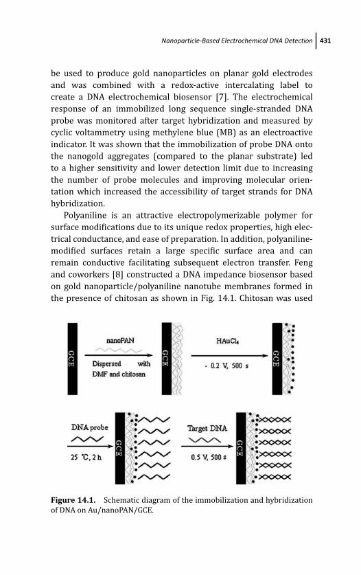
March 14, 2012 20:27 PSP Book - 9in x 6in 14-Ozsoz-c14
Nanoparticle-Based Electrochemical DNA Detection 431
be used to produce gold nanoparticles on planar gold electrodes
and was combined with a redox-active intercalating label to
create a DNA electrochemical biosensor [7]. The electrochemical
response of an immobilized long sequence single-stranded DNA
probe was monitored after target hybridization and measured by
cyclic voltammetry using methylene blue (MB) as an electroactive
indicator. It was shown that the immobilization of probe DNA onto
the nanogold aggregates (compared to the planar substrate) led
to a higher sensitivity and lower detection limit due to increasing
the number of probe molecules and improving molecular orien-
tation which increased the accessibility of target strands for DNA
hybridization.
Polyaniline is an attractive electropolymerizable polymer for
surface modifications due to its unique redox properties, high elec-
trical conductance, and ease of preparation. In addition, polyaniline-
modified surfaces retain a large specific surface area and can
remain conductive facilitating subsequent electron transfer. Feng
and coworkers [8] constructed a DNA impedance biosensor based
on gold nanoparticle/polyaniline nanotube membranes formed in
the presence of chitosan as shown in Fig. 14.1. Chitosan was used
Figure 14.1. Schematic diagram of the immobilization and hybridization
of DNA on Au/nanoPAN/GCE.
March 14, 2012 20:27 PSP Book - 9in x 6in 14-Ozsoz-c14
432 Nanomaterial-Based Electrochemical DNA Detection
as a dispersant for aniline which was then electropolymerized onto
a bare glassy carbon surface to form polyaniline nanotubes. The
polyaniline nanotubes then served to nucleate and electrochemically
grow gold nanoparticles upon which single-stranded DNA oligonu-
cleotide probes could be immobilized. This technique combined the
large surface areas of two different nanomaterials, the polyaniline
nanotubes and the gold nanoparticles, to increase conductivity
and create a unique sensing composite membrane which was
characterized by cyclic voltammetry and electrochemical impedance
spectroscopy. DNA hybridization was monitored by impedance and
used to detect the sequence specific DNA of the phosphinothricin
acetyltransferase gene that exists in some transgenic crops. The
dynamic detection range was from 1 × 10⁻¹² to 1 × 10⁻⁶ mol L−1,
the detection limit was 3.1 × 10⁻¹³ mol L−1, and the sensor showed
good selectivity, stability, and reproducibility.
14.2.3 Magnetic Particles
Magnetic (para- or super-) particles provide a means of both
immobilizing DNA and for separation and isolation from media
constituents in solution due to their ability to respond to an external
magnetic field [9]. Widely used as separation tools to purify many
biologically active compounds such as proteins, peptides, as well
as nucleic acids, they have also found use in electrochemical-
based DNA hybridization assays. The use of magnetic nanoparticle
probes has led to a “two-surface” strategy for improved biosensor
performance [10]. In traditional electrochemical DNA biosensors,
the probe recognition layer is directly immobilized onto the
electrode transducer with the hybridization and detection steps
being conducted on the same surface. The surface modification of
the transduction electrode, with immobilized single-stranded DNA
probes, can also act as an insulating layer and adversely affect the
electron-transfer kinetics for the detection method used. In contrast,
the two-surface approach allows for a separation of the hybridiza-
tion step, and after magnetic separation from nonhybridized DNA,
a fresh electrode can be used for detection. Additionally, the DNA-
bound magnetic particles which are suspended in the liquid phase
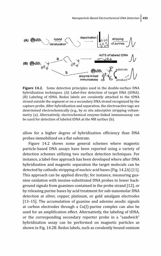
March 14, 2012 20:27 PSP Book - 9in x 6in 14-Ozsoz-c14
Nanoparticle-Based Electrochemical DNA Detection 433
Figure 14.2. Some detection principles used in the double-surface DNA
hybridization techniques. (A) Label-free detection of target DNA (tDNA).
(B) Labeling of tDNA. Redox labels are covalently attached to the tDNA
strand outside the segment or on a secondary DNA strand recognized by the
capture probe. After hybridization and separation, the electroactive tags are
determined electrochemically (e.g., by ex situ adsorptive stripping voltam-
metry (a). Alternatively, electrochemical enzyme-linked immunoassay can
be used for detection of labeled tDNA at the MB surface (b).
allow for a higher degree of hybridization efficiency than DNA
probes immobilized on a flat substrate.
Figure 14.2 shows some general schemes where magnetic
particle-based DNA assays have been reported using a variety of
detection schemes utilizing two surface detection techniques. For
instance, a label-free approach has been developed where after DNA
hybridization and magnetic separation the target molecule can be
detected by cathodic stripping of nucleic acid bases (Fig. 14.2A) [11].
This approach can be applied directly; for instance, measuring gua-
nine oxidation with inosine-substituted DNA probes to lower back-
ground signals from guanines contained in the probe strand [12], or
by releasing purine bases by acid treatment for sub-nanomolar DNA
detection at silver, copper, platinum, or gold amalgam electrodes
[13–15]. The accumulation of guanine and adenine anodic signals
at carbon electrodes through a Cu(I)-purine complex can also be
used for an amplification effect. Alternatively, the labeling of tDNA,
or the corresponding secondary reporter probe in a “sandwich”
hybridization assay can be performed on magnetic particles as
shown in Fig. 14.2B. Redox labels, such as covalently bound osmium
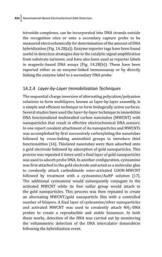
March 14, 2012 20:27 PSP Book - 9in x 6in 14-Ozsoz-c14
434 Nanomaterial-Based Electrochemical DNA Detection
tetroxide complexes, can be incorporated into DNA strands outside
the recognition sites or onto a secondary capture probe to be
measured electrochemically for determination of the amount of DNA
hybridization (Fig. 14.2B(a)). Enzyme reporter tags have been found
useful in detection strategies due to the catalytic signal amplification
from substrate turnover, and have also been used as reporter labels
in magnetic-based DNA assays (Fig. 14.2B(b)). These have been
reported either as an enzyme-linked immunoassay or by directly
linking the enzyme label to a secondary DNA probe.
14.2.4 Layer-by-Layer Immobilization Techniques
The sequential charge inversion of alternating polycation/polyanion
solutions to form multilayers, known as layer-by-layer assembly, is
a simple and efficient technique to form biologically active surfaces.
Several studies have used the layer-by-layer technique to immobilize
DNA functionalized multiwalled carbon nanotubes (MWCNT) with
nanoparticles that result in effective electrochemical DNA sensors.
In one report covalent attachment of Au nanoparticles and MWCNTs
was accomplished by first successively carboxylating the nanotubes
followed by cross-linking aminothiol groups to introduce thiol
functionalities [16]. Thiolated nanotubes were then adsorbed onto
a gold electrode followed by adsorption of gold nanoparticles. This
process was repeated 6 times until a final layer of gold nanoparticles
was used to adsorb probe DNA. In another configuration, cysteamine
was first attached to the gold electrode and acted as a molecular glue
to covalently attach carbodiimide ester-activated COOH-MWCNT
followed by treatment with a cysteamine/AuNP solution [17].
The additional cysteamine would subsequently conjugate to the
activated MWCNT while its free sulfur group would attach to
the gold nanoparticles. This process was then repeated to create
an alternating MWCNT/gold nanoparticle film with a controlled
number of bilayers. A final layer of cysteamine/silver nanoparticles
and activated MWCNT was used to covalently attach NH2-DNA
probes to create a reproducible and stable biosensor. In both
these works, detection of the DNA was carried out by monitoring
the voltammetric detection of the DNA intercalator doxorubicin
following the hybridization event.
March 14, 2012 20:27 PSP Book - 9in x 6in 14-Ozsoz-c14
Nanoparticle-Based Electrochemical DNA Detection 435
Figure 14.3. Schematic representation of the immobilization, hybridiza-
tion, and detection of probe DNA.
In another configuration silver nanoparticles were electrode-
posited onto the surface of a previously electro-polymerized
poly(trans-3(-pyridyl) acrylic acid)-multiwalled carbon nanotube,
glassy carbon electrode while DNA hybridization events were mon-
itored by differential pulse voltammetry (DPV) after intercalation
of adriamycin and chemisorption of thiolated single-stranded DNA
onto the silver nanoparticles, as shown in Fig. 14.3 [18]. Multiple
DNA assays were performed by de-hybridizing DNA duplexes with a
1:1 H2O:HNO3 solution for 15 min to regenerate the single-stranded
DNA surface. Both detection schemes showed high sensitivity,
selectivity, and reusability and took advantage of the synergistic
effects of combining carbon nanotubes to increase conductivity
and metal nanoparticles to provide a suitable platform for DNA
immobilization.
14.2.5 Metal Nanoparticle Labels for DNA HybridizationDetection
14.2.5.1 Direct detection of the nanoparticle label
Costa-Garcia and coworkers [19] first reported on using gold
nanoparticles to electrochemically monitor an affinity binding
March 14, 2012 20:27 PSP Book - 9in x 6in 14-Ozsoz-c14
436 Nanomaterial-Based Electrochemical DNA Detection
event by using an adsorbed biotinylated albumin layer to capture
streptavidin–gold conjugates on a pre-treated carbon paste elec-
trode. The colloidal gold label was detected following its oxidation at
a high potential in an acidic medium, and then reducing the released
AuCl–4 complex using differential pulse voltammetry. A modified
version of this detection principle was applied by the groups of
Limoges and Wang to detect DNA hybridization events based on
the oxidative dissolution of the particle in acidic bromine–bromide
solution and using highly sensitive stripping voltammetry [20,
21]. In the former case the 406-base pair human cytomegalovirus
DNA sequence was detected using oligonucleotide-modified gold
nanoparticle probes at probe-modified screen-printed microband
electrodes and had a detection limit of 5 pM. In the latter case
a two-surface technique was used to detect a DNA sequence
related to the BRCA1 breast cancer gene where magnetic bead
probe DNA complexes were used to hybridize to biotinylated DNA
that was conjugated to commercially available 10 nm streptavidin
gold nanoparticles. Following magnetic separation and nanoparticle
dissolution, the oxidized gold ions were used to determine the
amount of hybridized target at a thick-film screen-printed carbon
electrode using potentiometric stripping analysis. In both cases
a significant amplification signal can be attributed to metal
accumulation in the pre-concentration step of the stripping analysis
which makes the technique sensitive to the detection of trace
metals and particularly well suited for metal nanoparticle detection.
Further amplification can be performed after the hybridization
event by catalytically precipitating metals, such as gold and silver,
onto the nanoparticle label “seed”. Thus, more metal can be grown
in solution to increase the sensitivity of DNA hybridization binding
events [22]. Attomolar detection limits were achieved using a triple-
amplification strategy [23]. Instead of single nanoparticles being
used for each hybridization event, streptavidin-coated polystyrene
microspheres, each containing multiple biotinylated gold nanopar-
ticles and biotinylated DNA secondary capture probes were used.
Gold precipitation, acidic dissolution, and detection after DNA
hybridization resulted in a significant lowering of detection limits.
Wang et al. [24] also reported a solid-state detection method where,
after a silver-enhanced precipitation step, the enlarged gold–silver
March 14, 2012 20:27 PSP Book - 9in x 6in 14-Ozsoz-c14
Nanoparticle-Based Electrochemical DNA Detection 437
magnetic bead–DNA conjugate was collected by positioning a
magnet behind a screen-printed carbon electrode. The attraction of
the conjugate directly onto the working area of the electrode allowed
the stripping detection step to take place without dissolution of the
metal obviating the need for the caustic acidic medium.
Inorganic semiconductor nanocrystals have also found their
use as electrochemical labels for DNA detection. Cadmium sulfide,
for instance, was reported to be a viable alternative for gold
nanoparticles. After dissolution in nitric acid Cd+2 ions can be
detected at a mercury or bismuth film electrode [25]. Taking
advantage of the wide potential window and the fact that multiple
group II and III metals can be detected simultaneously at mercury
and bismuth film electrodes, a multitarget DNA hybridization
assay was developed using three different inorganic nanocrystals
(ZnS, CdS, and PbS) to simultaneously detect three different DNA
targets in the same solution [26]. A general scheme of Wang’s
nanoparticle magnetic bead-based protocol for electrochemical DNA
detection consisting of gold nanoparticles (A), silver enhancement
(B), magnetic collection and solid state detection (C), the use of CdS
(D), and multiple inorganic semiconducting encoding nanoparticles
(E) is presented in Fig. 14.4.
Merkoci and coworkers [27] have reported several works
describing DNA electrochemical biosensors based on the direct
determination of gold nanoparticles which have been adsorbed
onto the rough surface of graphite–epoxy composite electrodes,
their electrochemical oxidation at +1.25 V, and the detection of the
resulting tetrachloroaurate ions by differential pulse voltammetry.
The use of 1.4 nm Au67 particles allowed the 1:1 conjugation of
nanoparticle to magnetic bead-DNA probe and prevented cross-
linking effects resulting in lower detection limits over previous
assays [28]. A magnet placed into the graphite–epoxy electrode
transducer collected the hybridized DNA after magnetic separation
and allowed for the direct detection of the gold nanoparticle label.
Two other gold nanoparticle assays were described based on this
method using larger gold nanoparticles conjugated to DNA using
biotin/streptavidin interactions with the first being a two-strand
detection technique to detect the BRCA1 breast cancer gene, and
the second a sandwich assay to detect a DNA sequence related to

March 14, 2012 20:27 PSP Book - 9in x 6in 14-Ozsoz-c14
438 Nanomaterial-Based Electrochemical DNA Detection
Figure 14.4. Particle-based protocols for electrochemical detection of
DNA. These assays involve the introduction of the probe-attached onto the
magnetic particles, addition of the target/hybridization event, magnetic
removal of unwanted materials, binding of the metal, and amplified
electrochemical detection of the dissolved gold (Au) (A), silver (Ag) (B),
and cadmium sulfide (CdS) (D) nanoparticles. Me: metal tag. Also shown are
solid-state stripping (C) and multitarget (E) detection protocols.
the cystic fibrosis gene that could detect single- and three-base
mismatches [29]. The modification of gold nanoparticles with single
DNA bases was used to detect single nucleotide polymorphisms
(SNP), as described by Kerman et al. [30]. Phosphoramidite
chemistry was used to attach the monobases onto chitosan-modified
gold nanoparticles, which could then accumulate into a mismatched
DNA base pairing through Watson-Crick hydrogen base pairing in
the presence of DNA polymerase I. The electrochemical oxidation
signal of the gold nanoparticles could then be used to determine
the presence of mismatch sites in a synthetic 21-base DNA probe
related to tumor necrosis factor along with all its possible mutant
combinations. Liu et al. [31] subsequently reported a bioelectronic
method for coding SNPs using different encoding nanocrystals.

March 14, 2012 20:27 PSP Book - 9in x 6in 14-Ozsoz-c14
Nanoparticle-Based Electrochemical DNA Detection 439
Adenosine, cytosine, guanosine, and thymidine mononucleotides
were linked to ZnS, CdS, PbS, and CuSnanoparticles, respectively,
and sequentially introduced to a DNA hybrid-coated magnetic
bead solution. Characteristic multipotential voltammetric peaks
were produced depending on the base pairing of the different
nanocrystal-mononucleotide conjugates with each mutation capa-
ble of identifying each of eight possible one-base mutations in a
single run.
Ying has described two solid-state approaches based on the
incorporation of silver nanoparticles into DNA duplexes followed
by the direct detection of the nanoparticles based on an Ag/AgCl
cycling process shown in Fig. 14.5. In the first approach neutral
PNA, which can significantly increase DNA hybridization efficiency
due to a lack of electrostatic repulsion of the DNA target, was
used as the probe capture molecule [32]. Following target DNA
hybridization the surface would become negatively charged and
could then be labeled with positively charged dodecylamine-capped
Ag nanoparticles (Fig. 14.5A). In the second approach a normal
thiolated DNA mixed mono recognition layer was used in connection
Figure 14.5. Schematic for biosensing strategy using (A) dodecylamine-
capped Ag nanoparticles and (B) doxorubicin-modified Ag nanoparticles.
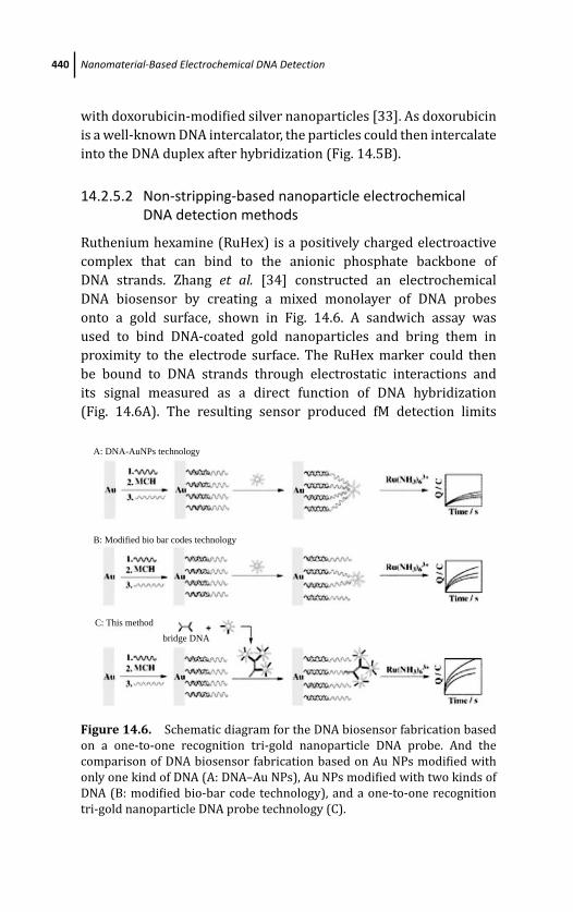
March 14, 2012 20:27 PSP Book - 9in x 6in 14-Ozsoz-c14
440 Nanomaterial-Based Electrochemical DNA Detection
with doxorubicin-modified silver nanoparticles [33]. As doxorubicin
is a well-known DNA intercalator, the particles could then intercalate
into the DNA duplex after hybridization (Fig. 14.5B).
14.2.5.2 Non-stripping-based nanoparticle electrochemicalDNA detection methods
Ruthenium hexamine (RuHex) is a positively charged electroactive
complex that can bind to the anionic phosphate backbone of
DNA strands. Zhang et al. [34] constructed an electrochemical
DNA biosensor by creating a mixed monolayer of DNA probes
onto a gold surface, shown in Fig. 14.6. A sandwich assay was
used to bind DNA-coated gold nanoparticles and bring them in
proximity to the electrode surface. The RuHex marker could then
be bound to DNA strands through electrostatic interactions and
its signal measured as a direct function of DNA hybridization
(Fig. 14.6A). The resulting sensor produced fM detection limits
A: DNA-AuNPs technology
B: Modified bio bar codes technology
C: This method
bridge DNA
Figure 14.6. Schematic diagram for the DNA biosensor fabrication based
on a one-to-one recognition tri-gold nanoparticle DNA probe. And the
comparison of DNA biosensor fabrication based on Au NPs modified with
only one kind of DNA (A: DNA–Au NPs), Au NPs modified with two kinds of
DNA (B: modified bio-bar code technology), and a one-to-one recognition
tri-gold nanoparticle DNA probe technology (C).
March 14, 2012 20:27 PSP Book - 9in x 6in 14-Ozsoz-c14
Nanoparticle-Based Electrochemical DNA Detection 441
with excellent differentiation for single base mismatches. The use
of gold nanoparticles provided a significant signal amplification
effect in that hundreds of DNA reporter strands were immobilized
on each particle thus increasing the amount of reporter RuHex
molecules that could bind. A modified “bio-bar code” technique that
mixes both complementary and noncomplementary DNA probes
on the modified gold nanoparticles limits the number of strands
available for hybridization of target molecules on the surface
(Fig. 14.6B) [35]. This subsequently decreases the number of DNA
interconnects on the transducer surface and has a profound impact
on the reproducibility and sensitivity of the technique. A DNA probe
bridge could be constructed that could combine two different gold
nanoparticle bio-bar codes. The DNA bridge gold nanoparticle bio-
bar code conjugate contained three gold nanoparticle labels and
only one linking DNA molecule for target binding (Fig. 14.6C). The
resulting tri-gold nanoparticle DNA probe combined the maximum
synergy of signal amplification, from the electrostatic binding of
ruthenium hexamine onto 486 DNA reporter probes on the three
gold nanoparticles, and increased selectivity from the one-to-one
recognition of the single target binding site to achieve a detection
limit of 53 aM. Li et al. [36] reported another version of this tech-
nique where an avidin/polyamidoamine (PAMAM) dendrimer/3-
mercaptopropionic acid layer was used to immobilize DNA probes.
The use of the PAMAM served as an additional amplification effect,
along with the use of gold nanoparticles to bind RuHex, due to
the increased amount of DNA probes that could be attached when
compared to a flat substrate and led to a low detection limit of
1.4 × 10⁻¹⁴ mol L−1.
Enzymes have found wide use as labels in biological assays due
to their ability to produce catalytic signals from the generation of
electroactive products. However, there are some inherent drawbacks
with using biological labels associated with their thermal and
environmental instabilities. The large surface area-to-volume ratio
of nanoparticles makes them superior catalysts when compared to
their bulk metal counterparts. Taking advantage of these catalytic
properties, Willner and coworkers [37] introduced the use of metal
nanoparticles as inorganic analogues to traditional enzyme tags by
using single-stranded DNA probe-modified platinum nanoparticles
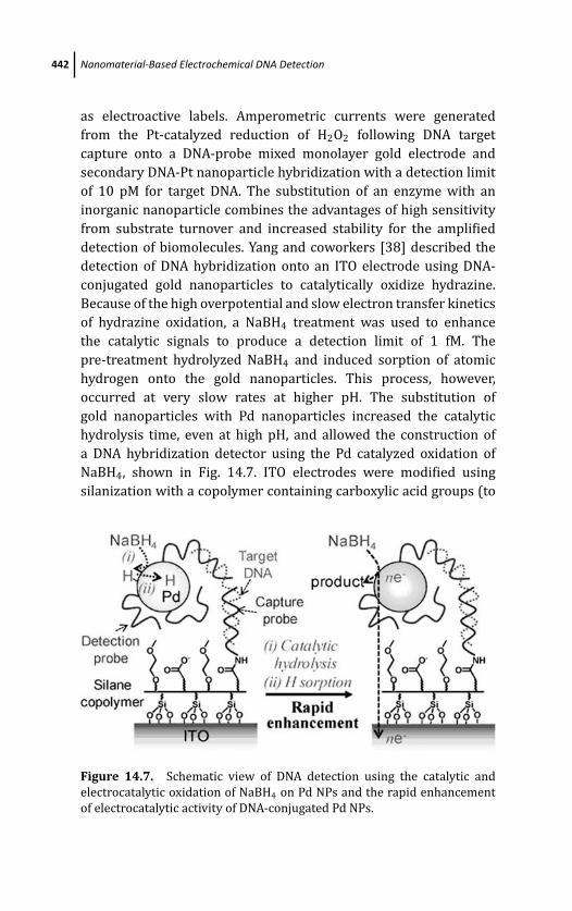
March 14, 2012 20:27 PSP Book - 9in x 6in 14-Ozsoz-c14
442 Nanomaterial-Based Electrochemical DNA Detection
as electroactive labels. Amperometric currents were generated
from the Pt-catalyzed reduction of H2O2 following DNA target
capture onto a DNA-probe mixed monolayer gold electrode and
secondary DNA-Pt nanoparticle hybridization with a detection limit
of 10 pM for target DNA. The substitution of an enzyme with an
inorganic nanoparticle combines the advantages of high sensitivity
from substrate turnover and increased stability for the amplified
detection of biomolecules. Yang and coworkers [38] described the
detection of DNA hybridization onto an ITO electrode using DNA-
conjugated gold nanoparticles to catalytically oxidize hydrazine.
Because of the high overpotential and slow electron transfer kinetics
of hydrazine oxidation, a NaBH4 treatment was used to enhance
the catalytic signals to produce a detection limit of 1 fM. The
pre-treatment hydrolyzed NaBH4 and induced sorption of atomic
hydrogen onto the gold nanoparticles. This process, however,
occurred at very slow rates at higher pH. The substitution of
gold nanoparticles with Pd nanoparticles increased the catalytic
hydrolysis time, even at high pH, and allowed the construction of
a DNA hybridization detector using the Pd catalyzed oxidation of
NaBH4, shown in Fig. 14.7. ITO electrodes were modified using
silanization with a copolymer containing carboxylic acid groups (to
Figure 14.7. Schematic view of DNA detection using the catalytic and
electrocatalytic oxidation of NaBH4 on Pd NPs and the rapid enhancement
of electrocatalytic activity of DNA-conjugated Pd NPs.
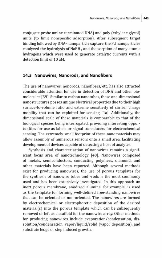
March 14, 2012 20:27 PSP Book - 9in x 6in 14-Ozsoz-c14
Nanowires, Nanorods, and Nanofibers 443
conjugate probe amine-terminated DNA) and poly (ethylene glycol)
units (to limit nonspecific adsorption). After subsequent target
binding followed by DNA–nanoparticle capture, the Pd nanoparticles
catalyzed the hydrolysis of NaBH4 and the sorption of many atomic
hydrogens which were used to generate catalytic currents with a
detection limit of 10 aM.
14.3 Nanowires, Nanorods, and Nanofibers
The use of nanowires, nonorods, nanofibers, etc. has also attracted
considerable attention for use in detection of DNA and other bio-
molecules [39]. Similar to carbon nanotubes, these one-dimensional
nanostructures posses unique electrical properties due to their high
surface-to-volume ratio and extreme sensitivity of carrier charge
mobility that can be exploited for sensing [1a]. Additionally, the
dimensional scale of these materials is comparable to that of the
biological species being interrogated, providing interesting oppor-
tunities for use as labels or signal transducers for electrochemical
sensing. The extremely small footprint of these nanomaterials may
allow assembly of numerous sensors onto a small area, facilitating
development of devices capable of detecting a host of analytes.
Synthesis and characterization of nanowires remains a signif-
icant focus area of nanotechnology [40]. Nanowires composed
of metals, semiconductors, conducting polymers, diamond, and
other materials have been reported. Although several methods
exist for producing nanowires, the use of porous templates for
the synthesis of nanowire tubes and -rods is the most commonly
used and has been extensively investigated. In this approach an
inert porous membrane, anodized alumina, for example, is used
as the template for forming well-defined free-standing nanowires
that can be oriented or non-oriented. The nanowires are formed
by electrochemical or electrophoretic deposition of the desired
material(s) into the porous template which can be subsequently
removed or left as a scaffold for the nanowire array. Other methods
for producing nanowires include evaporation/condensation, dis-
solution/condensation, vapor/liquid/solid (vapor deposition), and
substrate ledge or step induced growth.
March 14, 2012 20:27 PSP Book - 9in x 6in 14-Ozsoz-c14
444 Nanomaterial-Based Electrochemical DNA Detection
14.3.1 Nanorods as Labels
Use of nanorods as labels for electrochemical detection of DNA was
first reported by Wang and coworkers [41]. In this work conical
indium/gold nanorods, approximately 3 to 5 μm in length, were
synthesized via sequential electrodeposition of Au and indium into
alumina membranes. Following synthesis, the alumina template
was dissolved in 3 M NaOH yielding free nanorods (Fig. 14.8B).
These rods were then modified with thiolated oligonucleotide
detection probes, complementary to a portion of the target DNA, via
Figure 14.8. (A) Schematic representation showing sandwich hybridiza-
tion linking magnetic beads and indium/gold nanorods through the DNA
target, magnetic collection of the DNA-linked particle assembly onto the
thick-film electrode transducer, and solid-state derivative chronopotentio-
metric measurements of the captured indium rods. P1, DNA probe 1; T, DNA
target; P2, DNA probe 2; MR, indium/gold nanorods; MB, magnetic beads;
and M, external magnet. SEM images of (B) indium/gold rods and (C) DNA-
linked particle assembly (after sandwich hybridization assay).
March 14, 2012 20:27 PSP Book - 9in x 6in 14-Ozsoz-c14
Nanowires, Nanorods, and Nanofibers 445
thiol–gold interactions. In the presence of target DNA, a sandwich
was formed between magnetic beads modified with capture
probe DNA, the target DNA, and the detection probe modified
indium/gold nanorods. This is shown schematically in Fig. 14.8A.
Detection occurred by either solid-state chronopotentiometry of the
indium/gold nanorods collected at a mercury-coated screen-printed
carbon electrode by an external magnet, or chronopotentiometric
stripping of the indium label, following dissolution under acidic
conditions, at a mercury-coated carbon-fiber electrode. The use of
the nanorods as labels allowed detection of 30 ng/L (250 zmol)
target DNA.
14.3.2 Nanowires Interfaced with Electrodes as anImmobilization Matrix
Nanowires have also been used as an immobilization matrix for
probe DNA with inherent enhanced electron-transfer kinetics and
higher surface area. Electroactive reporter molecules are then used
to measure immobilized DNA. Kelley’s group has reported a platform
for electrochemical DNA detection using arrayed gold nanowires
generated by electroless deposition of gold onto polycarbonate
membranes (see Fig. 14.9A), which were exposed by subsequent
oxygen plasma etching (Fig. 14.9B) [42]. Thiolated probe DNA
was deposited onto the gold nanowire array and [Ru(NH3)6]3+
and [Fe(CN)6]3− were used as electrocatalytic reporters for the
amount of hybridized target DNA, as shown in Fig. 14.9C, yielding
an attomole-level detection limit. The authors showed that catalytic
currents and diffusional mobility of Ru3+ ions at the nanowire array
are markedly different than that obtained at bulk macroelectrodes
allowing for improved signal-to-noise ratio and sensitivity [43].
These results demonstrate the utility three-dimensional nanoscale
systems can posses over bulk macroscale systems. Very recently,
Kelley’s group reported an extension of their work in which peptide
nucleic acid (PNA) probes were immobilized onto gold nanowire-
modified polycarbonate membranes and again used [Ru(NH3)6]3+
and [Fe(CN)6]3−as electrocatalytic reporters [44]. Unlike DNA, the
peptide backbone of the PNA probe resulted in a neutral charged
surface that provided significantly decreased background signals. In
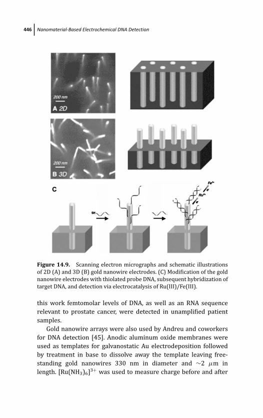
March 14, 2012 20:27 PSP Book - 9in x 6in 14-Ozsoz-c14
446 Nanomaterial-Based Electrochemical DNA Detection
Figure 14.9. Scanning electron micrographs and schematic illustrations
of 2D (A) and 3D (B) gold nanowire electrodes. (C) Modification of the gold
nanowire electrodes with thiolated probe DNA, subsequent hybridization of
target DNA, and detection via electrocatalysis of Ru(III)/Fe(III).
this work femtomolar levels of DNA, as well as an RNA sequence
relevant to prostate cancer, were detected in unamplified patient
samples.
Gold nanowire arrays were also used by Andreu and coworkers
for DNA detection [45]. Anodic aluminum oxide membranes were
used as templates for galvanostatic Au electrodeposition followed
by treatment in base to dissolve away the template leaving free-
standing gold nanowires 330 nm in diameter and ∼2 μm in
length. [Ru(NH3)6]3+ was used to measure charge before and after
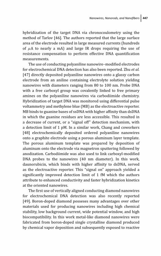
March 14, 2012 20:27 PSP Book - 9in x 6in 14-Ozsoz-c14
Nanowires, Nanorods, and Nanofibers 447
hybridization of the target DNA via chronocoulometry using the
method of Tarlov [46]. The authors reported that the large surface
area of the electrode resulted in large measured currents (hundreds
of μA to nearly a mA) and large IR drops requiring the use of
resistance compensation to perform effective DNA quantification
measurements.
The use of conducting polyaniline nanowire–modified electrodes
for electrochemical DNA detection has also been reported. Zhu et al.[47] directly deposited polyaniline nanowires onto a glassy carbon
electrode from an aniline containing electrolyte solution yielding
nanowires with diameters ranging from 80 to 100 nm. Probe DNA
with a free carboxyl group was covalently linked to free primary
amines on the polyaniline nanowires via carbodiimide chemistry.
Hybridization of target DNA was monitored using differential pulse
voltammetry and methylene blue (MB) as the electroactive reporter.
MB binds to guanine bases of ssDNA with higher affinity than dsDNA
in which the guanine residues are less accessible. This resulted in
a decrease of current, or a “signal off” detection mechanism, with
a detection limit of 1 pM. In a similar work, Chang and coworkers
[48] electrochemically deposited ordered polyaniline nanowires
onto a graphite electrode using a porous aluminum layer template.
The porous aluminum template was prepared by deposition of
aluminum onto the electrode via magnetron sputtering followed by
anodization. Carbodiimide was also used to link carboxyl-modified
DNA probes to the nanowires (40 nm diameter). In this work,
daunorubicin, which binds with higher affinity to dsDNA, served
as the electroactive reporter. This “signal on” approach yielded a
significantly improved detection limit of 1 fM which the authors
attribute to enhanced conductivity and faster hybridization kinetics
at the oriented nanowires.
The first use of vertically aligned conducting diamond nanowires
for electrochemical DNA detection was also recently reported
[49]. Boron-doped diamond posseses many advantages over other
materials used for producing nanowires including high chemical
stability, low background current, wide potential window, and high
biocompatibility. In this work metal-like diamond nanowires were
fabricated from boron-doped single crystalline diamond produced
by chemical vapor deposition and subsequently exposed to reactive
March 14, 2012 20:27 PSP Book - 9in x 6in 14-Ozsoz-c14
448 Nanomaterial-Based Electrochemical DNA Detection
Figure 14.10. (A) SEM image of vertically aligned conducting diamond
nanowires. Examples of detection of DNA hybridization by (B) cyclic voltam-
metry, and (C) differential pulse voltammetry. Target DNA concentration
was 10 nM.
ion etching using diamond nanoparticles as hard etch masks to form
nanowires, as shown in Fig. 14.10A. The tips of the wires were
functionalized with aminophenyl groups by electrodeposition of
nitrophenyl diazonium followed by electroreduction of nitro groups
to amines. A heterobifunctional crosslinker was used to covalently
link the free amine groups on the diamond nanowires to thiol-
modified DNA probes. [Fe(CN)6]3− was used as a redox probe in
which peak currents would decrease upon hybridization of target
DNA yielding an ∼2 pM detection limit (see Fig. 14.10B, C). This
conducting diamond nanowire sensor proved 100 to 1000 times
more sensitive than sensors composed of smooth gold or diamond
surfaces.
14.3.3 Nanowire Conductance Based DNA Detection
Nanowires have been used to bridge two closely spaced electrodes
for DNA detection by monitoring the conductance of the nanowire
during hybridization. Binding of the negatively charged DNA strand
to the nanowire increases the net negative surface charge density
leading to an increase in conductance between the two electrodes.
This method is analogous to field-effect transistor (FET) switches
used in microelectronics in which the electrodes serve as the
electron source and drain while the nanowire serves as the
modulating gate [39]. In addition to being label-free and reagentless,
March 14, 2012 20:27 PSP Book - 9in x 6in 14-Ozsoz-c14
Nanowires, Nanorods, and Nanofibers 449
this approach also allows for real-time detection of target DNA [1a].
As these devices are very sensitive to changes in conductance, they
suffer from high sensitivity to the sample solution ionic properties
and impurities found in complex detection matrices.
Silicon nanowires were employed by both Hahm and Lieber
[50] and Li et al. [51] for the label-free real-time detection of
ssDNA sequences via conductometric monitoring of target DNA
hybridization. In the work of Li, ssDNA probes with acrylic
phosphoramidite functionality were immobilized to a silicon
nanowire which had been previously exposed to the vapor
of 3-mercaptopropyltrimethoxysilane. By monitoring changes in
conductance target DNA 12-mer strands could be detected at
concentrations as low as 25 pM, and the sensor showed excellent
discrimination against single-base mismatch sequences. Hahm and
Lieber employed biotinylated PNA probes conjugated to a silicon
nanowire, previously modified with biotin followed by avidin, to
detect 31-mer DNA strands. PNA probes were chosen over DNA
probes due to their higher affinity for DNA, greater stability,
and neutral charge. A detection limit of 10 fM was reported for
this system along with good discrimination against single-base
mismatch sequences, and similar changes in conductance from
device to device. A top-down approach was also recently reported
for producing an array of highly ordered silicon nanowires for
DNA detection [52]. This method resulted in high uniformity and
reproducibility and allows for simpler scaling and manufacturing of
the sensor. Similar to the work of Hahm and Leiber, this sensor was
modified with PNA probes and yielded a 10 fM detection limit.
Multisegment CdTe-Au-CdTe nanowires have also been used
for FET-based sensing of DNA [53]. Synthesized by consecu-
tive electrodeposition onto an anodized alumina template these
metal-semiconductor nanowires exhibit a p-type behavior. Thiol-
terminated ssDNA probes were bound via Au–thiol interaction to the
Au segment of the nanowires. Target DNA could be detected at 1 μM
and higher concentrations.
In a recent report, Kong and coworkers [54] developed a
conductometric DNA sensor in which captured target DNA serves
as the template for electroless silver deposition forming silver
nanowires. In this work, interdigitated electrodes were formed onto
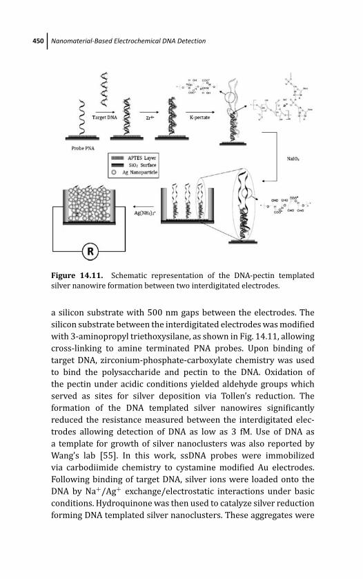
March 14, 2012 20:27 PSP Book - 9in x 6in 14-Ozsoz-c14
450 Nanomaterial-Based Electrochemical DNA Detection
Figure 14.11. Schematic representation of the DNA-pectin templated
silver nanowire formation between two interdigitated electrodes.
a silicon substrate with 500 nm gaps between the electrodes. The
silicon substrate between the interdigitated electrodes was modified
with 3-aminopropyl triethoxysilane, as shown in Fig. 14.11, allowing
cross-linking to amine terminated PNA probes. Upon binding of
target DNA, zirconium-phosphate-carboxylate chemistry was used
to bind the polysaccharide and pectin to the DNA. Oxidation of
the pectin under acidic conditions yielded aldehyde groups which
served as sites for silver deposition via Tollen’s reduction. The
formation of the DNA templated silver nanowires significantly
reduced the resistance measured between the interdigitated elec-
trodes allowing detection of DNA as low as 3 fM. Use of DNA as
a template for growth of silver nanoclusters was also reported by
Wang’s lab [55]. In this work, ssDNA probes were immobilized
via carbodiimide chemistry to cystamine modified Au electrodes.
Following binding of target DNA, silver ions were loaded onto the
DNA by Na+/Ag+ exchange/electrostatic interactions under basic
conditions. Hydroquinone was then used to catalyze silver reduction
forming DNA templated silver nanoclusters. These aggregates were
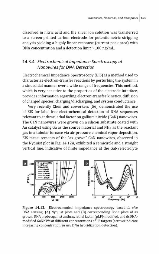
March 14, 2012 20:27 PSP Book - 9in x 6in 14-Ozsoz-c14
Nanowires, Nanorods, and Nanofibers 451
dissolved in nitric acid and the silver ion solution was transferred
to a screen-printed carbon electrode for potentiometric stripping
analysis yielding a highly linear response (current peak area) with
DNA concentration and a detection limit ∼100 ng/mL.
14.3.4 Electrochemical Impedance Spectroscopy atNanowires for DNA Detection
Electrochemical Impedance Spectroscopy (EIS) is a method used to
characterize electron-transfer reactions by perturbing the system in
a sinusoidal manner over a wide range of frequencies. This method,
which is very sensitive to the properties of the electrode interface,
provides information regarding electron-transfer kinetics, diffusion
of charged species, charging/discharging, and system conductance.
Very recently Chen and coworkers [56] demonstrated the use
of EIS for label-free electrochemical detection of DNA sequences
relevant to anthrax lethal factor on gallium nitride (GaN) nanowires.
The GaN nanowires were grown on a silicon substrate coated with
Au catalyst using Ga as the source material and NH3 as the reactant
gas in a tubular furnace via air pressure chemical vapor deposition.
EIS measurements of the “as grown” GaN nanowires, observed in
the Nyquist plot in Fig. 14.12A, exhibited a semicircle and a straight
vertical line, indicative of finite impedance at the GaN/electrolyte
Figure 14.12. Electrochemical impedance spectroscopy based in situDNA sensing: (A) Nyquist plots and (B) corresponding Bode plots of as
grown, DNA probe against anthrax lethal factor (pLF)-modified, and dsDNA-
modified GaNNWs at different concentrations of LF targets (arrows indicate
increasing concentration, in situ DNA hybridization detection).
March 14, 2012 20:27 PSP Book - 9in x 6in 14-Ozsoz-c14
452 Nanomaterial-Based Electrochemical DNA Detection
interface and suppressed diffusion-limited electrochemical behav-
ior. Interestingly, upon binding of thiolated probe DNA to 3-
mercaptopropyl trimethoxysilane-modified GaN nanowires, two
semicircles were observed. The first semicircle was now indicative
of charge transfer at the GaN–DNA interface, with the second
semicircle indicative of charge transfer at the DNA–electrolyte
interface. These two phenomena are more clearly observed in the
two peaks in the Bode plot shown in Fig. 14.12B. The deconvolution
of the charge transfer properties of these two interfaces allowed for
monitoring the extent of DNA hybridization (decrease in resistance
to charge transfer in the semicircle corresponding to the GaN/DNA
interface, shown in Fig. 14.12A) while the second interface served
as a fingerprint for modification of the nanowires with DNA.
Picomolar concentrations of target DNA, even in the presence of
noncomplementary and mismatched sequences, were reported.
14.3.5 Dendrimers
Dendritic polymers, or dendrimers, are three-dimensional nano-
sized synthetic molecules possessing a regularly branched tree-
like structure. Dendrimers can be described as covalent micelles
having well-defined cavities, being nontoxic/biocompatible, and can
contain several functional groups allowing for functionalization
and/or immobilization of the dendrimers [57]. Several schemes
utilizing dendrimers for electrochemical detection of DNA have
been reported. In these reports dendrimers are either loaded
with electroactive reporter molecules and used as labels for DNA
detection, or immobilized on electrodes as scaffolds for DNA
immobilization providing higher probe densities and improved
electron transfer to the electrode.
Commercially available poly(amidoamine) (PAMAM)
dendrimers are the most commonly used dendrimers for electro-
chemical DNA detection. Recently, Zhu and coworkers [58] reported
the use of a new class of PAMAM dendrimers with a trimesyl core
and terminal carboxyl groups for DNA detection. Amine-modified
target DNA was immobilized to the dendrimer using carbodiimide
chemistry. Amine functionalized probe DNA was also immobilized
to a mercaptoacetic acid self-assembling monolayer (SAM)-modified
March 14, 2012 20:27 PSP Book - 9in x 6in 14-Ozsoz-c14
Nanowires, Nanorods, and Nanofibers 453
Au electrode via carbodiimide chemistry. EIS in the presence of
[Fe(CN)6]3− [also referred to as faradic impedance spectroscopy
(FIS)] was employed to detect dendrimer-labeled target DNA
hybridization. Upon hybridization, the negatively charged den-
drimer on the electrode surface induced electrostatic repulsion of
the negatively charged [Fe(CN)6]3− reporter. Monitoring resistance
to charge transfer by FIS resulted in a detection limit of 2.5 pM. This
sensitivity was two orders of magnitude lower than that obtained
for target DNA without the PAMAM dendrimer label. Similar results
were obtained by Humenik et al. [59] utilizing detection probe
DNA conjugated with PAMAM dendrimers that had been loaded
with esterase enzymes. These polyvalent esterase dendrimer DNA
clusters were hybridized to captured target DNA immobilized on
an Au electrode in a sandwich assay format. The amperometric
signal of p-aminophenol produced by the esterase enzymes was
used indirectly to detect DNA and resulted in a detection limit of
20 fM. This provided a 100-fold signal enhancement over use of
monovalent esterase-detection DNA probe conjugates.
Immobilization of PAMAM dendrimers on Au electrodes previ-
ously modified with SAMs has also been reported. Zhu et al. [60]
utilized a carboxyl terminated SAM to crosslink amine-terminated
PAMAM dendrimers via carbodiimide chemistry to an Au electrode.
This was followed by immobilization of phosphate-modified probe
DNA by phosphoramidate bond formation. Daunorubicin was used
as an electroactive indicator of target DNA hybridization. In a similar
work, Li and coworkers [61] used glutaraldehyde to immobilize
amine-terminated PAMAM to an Au electrode modified with an
amine-terminated SAM, followed by conjugation of the dendrimer
with amine-modified probe DNA, again with glutaraldehyde. FIS
with [Fe(CN)6]3− reporter was used to monitor changes in surface
charge and electron-transfer properties upon binding of target DNA.
The detection limit for both systems was similar: 8 pM using DPV
and daunorubicin, and 3.8 pM using FIS and [Fe(CN)6]3−. Both
reports demonstrated higher sensitivity for DNA when dendrimers
were used as compared to SAM-modified electrodes alone. This was
attributed to the higher surface area of dendrimer-modified sur-
faces significantly improving the immobilization capacity of probe
DNA.
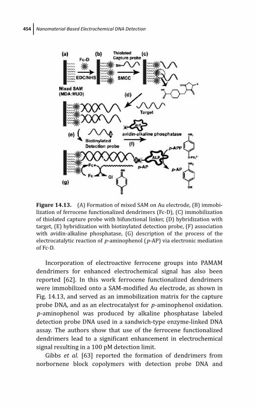
March 14, 2012 20:27 PSP Book - 9in x 6in 14-Ozsoz-c14
454 Nanomaterial-Based Electrochemical DNA Detection
Figure 14.13. (A) Formation of mixed SAM on Au electrode, (B) immobi-
lization of ferrocene functionalized dendrimers (Fc-D), (C) immobilization
of thiolated capture probe with bifunctional linker, (D) hybridization with
target, (E) hybridization with biotinylated detection probe, (F) association
with avidin-alkaline phosphatase, (G) description of the process of the
electrocatalytic reaction of p-aminophenol ( p-AP) via electronic mediation
of Fc-D.
Incorporation of electroactive ferrocene groups into PAMAM
dendrimers for enhanced electrochemical signal has also been
reported [62]. In this work ferrocene functionalized dendrimers
were immobilized onto a SAM-modified Au electrode, as shown in
Fig. 14.13, and served as an immobilization matrix for the capture
probe DNA, and as an electrocatalyst for p-aminophenol oxidation.
p-aminophenol was produced by alkaline phosphatase labeled
detection probe DNA used in a sandwich-type enzyme-linked DNA
assay. The authors show that use of the ferrocene functionalized
dendrimers lead to a significant enhancement in electrochemical
signal resulting in a 100 pM detection limit.
Gibbs et al. [63] reported the formation of dendrimers from
norbornene block copolymers with detection probe DNA and
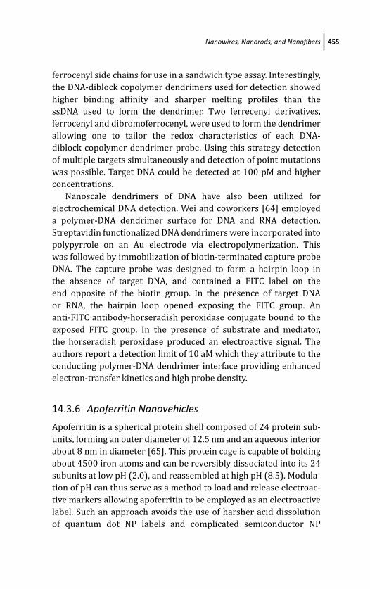
March 14, 2012 20:27 PSP Book - 9in x 6in 14-Ozsoz-c14
Nanowires, Nanorods, and Nanofibers 455
ferrocenyl side chains for use in a sandwich type assay. Interestingly,
the DNA-diblock copolymer dendrimers used for detection showed
higher binding affinity and sharper melting profiles than the
ssDNA used to form the dendrimer. Two ferrecenyl derivatives,
ferrocenyl and dibromoferrocenyl, were used to form the dendrimer
allowing one to tailor the redox characteristics of each DNA-
diblock copolymer dendrimer probe. Using this strategy detection
of multiple targets simultaneously and detection of point mutations
was possible. Target DNA could be detected at 100 pM and higher
concentrations.
Nanoscale dendrimers of DNA have also been utilized for
electrochemical DNA detection. Wei and coworkers [64] employed
a polymer-DNA dendrimer surface for DNA and RNA detection.
Streptavidin functionalized DNA dendrimers were incorporated into
polypyrrole on an Au electrode via electropolymerization. This
was followed by immobilization of biotin-terminated capture probe
DNA. The capture probe was designed to form a hairpin loop in
the absence of target DNA, and contained a FITC label on the
end opposite of the biotin group. In the presence of target DNA
or RNA, the hairpin loop opened exposing the FITC group. An
anti-FITC antibody-horseradish peroxidase conjugate bound to the
exposed FITC group. In the presence of substrate and mediator,
the horseradish peroxidase produced an electroactive signal. The
authors report a detection limit of 10 aM which they attribute to the
conducting polymer-DNA dendrimer interface providing enhanced
electron-transfer kinetics and high probe density.
14.3.6 Apoferritin Nanovehicles
Apoferritin is a spherical protein shell composed of 24 protein sub-
units, forming an outer diameter of 12.5 nm and an aqueous interior
about 8 nm in diameter [65]. This protein cage is capable of holding
about 4500 iron atoms and can be reversibly dissociated into its 24
subunits at low pH (2.0), and reassembled at high pH (8.5). Modula-
tion of pH can thus serve as a method to load and release electroac-
tive markers allowing apoferritin to be employed as an electroactive
label. Such an approach avoids the use of harsher acid dissolution
of quantum dot NP labels and complicated semiconductor NP
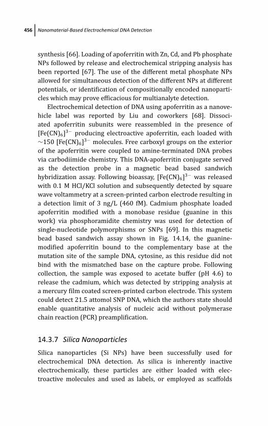
March 14, 2012 20:27 PSP Book - 9in x 6in 14-Ozsoz-c14
456 Nanomaterial-Based Electrochemical DNA Detection
synthesis [66]. Loading of apoferritin with Zn, Cd, and Pb phosphate
NPs followed by release and electrochemical stripping analysis has
been reported [67]. The use of the different metal phosphate NPs
allowed for simultaneous detection of the different NPs at different
potentials, or identification of compositionally encoded nanoparti-
cles which may prove efficacious for multianalyte detection.
Electrochemical detection of DNA using apoferritin as a nanove-
hicle label was reported by Liu and coworkers [68]. Dissoci-
ated apoferritin subunits were reassembled in the presence of
[Fe(CN)6]3− producing electroactive apoferritin, each loaded with
∼150 [Fe(CN)6]3− molecules. Free carboxyl groups on the exterior
of the apoferritin were coupled to amine-terminated DNA probes
via carbodiimide chemistry. This DNA-apoferritin conjugate served
as the detection probe in a magnetic bead based sandwich
hybridization assay. Following bioassay, [Fe(CN)6]3− was released
with 0.1 M HCl/KCl solution and subsequently detected by square
wave voltammetry at a screen-printed carbon electrode resulting in
a detection limit of 3 ng/L (460 fM). Cadmium phosphate loaded
apoferritin modified with a monobase residue (guanine in this
work) via phosphoramidite chemistry was used for detection of
single-nucleotide polymorphisms or SNPs [69]. In this magnetic
bead based sandwich assay shown in Fig. 14.14, the guanine-
modified apoferritin bound to the complementary base at the
mutation site of the sample DNA, cytosine, as this residue did not
bind with the mismatched base on the capture probe. Following
collection, the sample was exposed to acetate buffer (pH 4.6) to
release the cadmium, which was detected by stripping analysis at
a mercury film coated screen-printed carbon electrode. This system
could detect 21.5 attomol SNP DNA, which the authors state should
enable quantitative analysis of nucleic acid without polymerase
chain reaction (PCR) preamplification.
14.3.7 Silica Nanoparticles
Silica nanoparticles (Si NPs) have been successfully used for
electrochemical DNA detection. As silica is inherently inactive
electrochemically, these particles are either loaded with elec-
troactive molecules and used as labels, or employed as scaffolds
March 14, 2012 20:27 PSP Book - 9in x 6in 14-Ozsoz-c14
Nanowires, Nanorods, and Nanofibers 457
Figure 14.14. Schematic of an electrochemical SNP quantitative assay
based on nanoparticle probe and sequential dna hybridization.
for DNA immobilization resulting in higher probe density and
improved electron transfer to the underlying electrode. The use
of [Co(bpy)3]3+-doped Si NPs as labels for electrochemical DNA
detection was reported by Zhu et al. [70]. In this work [Co(bpy)3]3+
molecules were loaded into Si NPs during NP synthesis, and
then conjugated to amine-terminated ssDNA detection probes via
trimethoxysilylpropydiethylenetriamine and glutaraldehyde. This
now electroactive Si NP functionalized detection probe was used
in a sandwich assay format with capture probe DNA immobilized
onto a glassy carbon electrode. The high loading of [Co(bpy)3]3+
molecules in the Si NPs resulted in a 200 pM target DNA detection
limit. The response from a three-base pair mismatch sequence and
noncomplementary sequence was negligible.
Recently, Ma and coworkers [71] reported the use of Si NP
films for enhanced electrochemical DNA detection. Si NPs were
March 14, 2012 20:27 PSP Book - 9in x 6in 14-Ozsoz-c14
458 Nanomaterial-Based Electrochemical DNA Detection
deposited onto a p-aminothiophenol SAM on an Au electrode by
either electrodeposition of the Si NPs from a silica sol, or adsorption
of the Si NPs upon dipping the SAM-modified electrode into a silica
sol/Si NP solution for several hours. Electrodeposition of the Si
NP provided the best Si NP loading, increasing immobilized ssDNA
probe density and improved electron-transfer kinetics compared
to the SAM-modified electrode alone. FIS allowed for detection
of target DNA hybridization with a detection limit of 1.5 pM and
discrimination between single or double base pair mismatched
DNA sequences. A similar Si NP-SAM-modified Au electrode system
employing [Co(bpy)3]3+ as the electroactive reporter and differen-
tial pulse voltammetry for DNA detection has also been reported
[72].
14.3.8 Liposomes
Liposomes are aggregates of amphiphilic block copolymers or sur-
factant molecules that self-assemble into spherical nanostructures
in aqueous solution. Typically, liposomes consist of a bilayer in
which hydrophilic blocks of the polymer form the outer and inner
shell of the bilayer while the hydrophobic blocks lie between the
inner and outer shell. This configuration shields the hydrophobic
blocks from the external aqueous solution and the aqueous internal
core of the liposome. Liposomes can be functionalized with various
biomolecules and loaded during the self-assembly process with
reporters facilitating use of liposomes as effective labels for DNA
detection.
Patolsky et al. [73] reported the use of 220 ± 20 nm diam-
eter negatively charged liposomes with maleimide functionality
for electrochemical detection of DNA. Thiol-terminated detection
probe DNA was immobilized onto the maleimide functionalized
liposomes yielding 50 to 60 bound DNA probes per liposome.
These DNA-modified liposomes were hybridized to captured target
DNA which was previously immobilized onto a probe DNA-
modified Au electrode in a sandwich assay format, as shown in
Fig. 14.15A. The strong negative surface charge of the DNA-modified
liposomes prevented nonspecific interactions with the negatively
charged electrode surface, providing very low background signals.
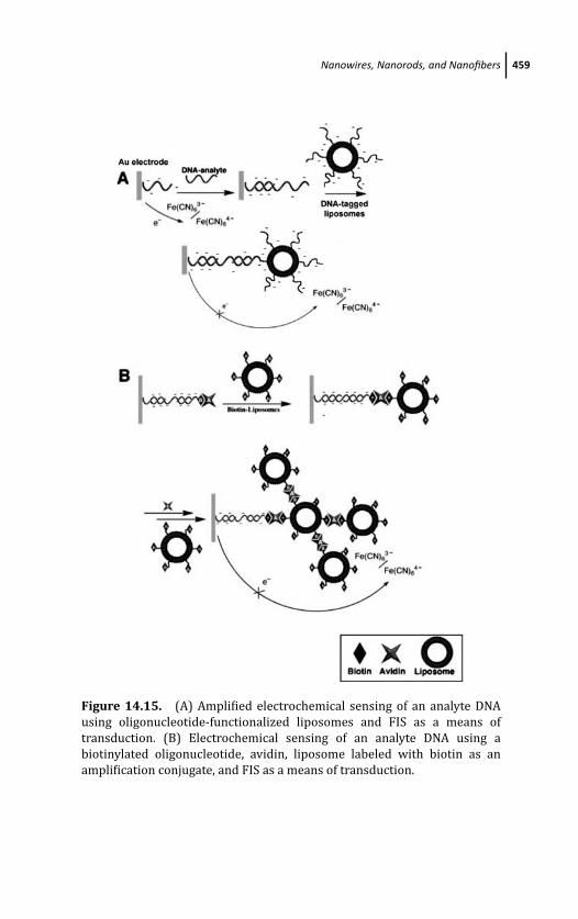
March 14, 2012 20:27 PSP Book - 9in x 6in 14-Ozsoz-c14
Nanowires, Nanorods, and Nanofibers 459
Figure 14.15. (A) Amplified electrochemical sensing of an analyte DNA
using oligonucleotide-functionalized liposomes and FIS as a means of
transduction. (B) Electrochemical sensing of an analyte DNA using a
biotinylated oligonucleotide, avidin, liposome labeled with biotin as an
amplification conjugate, and FIS as a means of transduction.
March 14, 2012 20:27 PSP Book - 9in x 6in 14-Ozsoz-c14
460 Nanomaterial-Based Electrochemical DNA Detection
In addition, hybridization of the liposome-labeled detection probe
DNA to the electrode led to a significant negatively charged electrode
interface, which repelled the negatively charged [Fe(CN)6]3– redox
probe. This increase in resistance to charge transfer to the redox
probe was monitored using FIS resulting in a detection limit of
1.2 pM. The authors also used a biotinylated detection probe DNA
that after binding to target DNA on the electrode surface (see
Fig. 14.15B), was treated with avidin, allowing subsequent capture
of biotinlyated liposomes. This was again followed by treatment
with avidin and biotinylated liposomes forming large aggregates of
liposomes yielding a very high negatively charged surface density.
The detection limit for this system was 50 fM.
In an extension of this work biotin-labeled liposomes were also
modified with horseradish peroxidase (HRP) via periodate oxidation
chemistry [74]. The HRP loaded biotin-labeled liposomes catalyzed
oxidation of 4-chloro-1-naphthol in the presence of H2O2 yielding an
insoluble product which precipitated onto and fouled the electrode.
FIS was used to monitor resistance of electron transfer to the
[Fe(CN)6]3− redox probe resulting a similar detection limit of 650 fM
for a DNA sequence relevant to Tay-Sachs disorder. The authors also
extended these various approaches to probe and amplify the signal
from single-base mismatches in analyte DNA [75].
Loading the aqueous interior of liposomes with electroactive
molecules has also been reported. Liposomes prepared with
cholesterol-labeled detection probe DNA and loaded with
[Fe(CN)6]3− were used in a magnetic bead based sandwich assay
in a glass-chip PDMS microfluidic device [76]. Collected by the
magnet upstream of an interdigitated ultramicroelectrode array
(IDUA), the liposomes were lysed by addition of detergent. The
released [Fe(CN)6]3− was subsequently detected at the downstream
IDUA. The assay took less than 30 minutes to perform, including
hybridization time, and could detect 1 fmol DNA. This electroactive
liposome magnetic bead-based sandwich assay was also recently
used by the authors to detect the mRNA amplified from a single
oocyst (an immature ovum) within a PMMA biosensor [77].
Liposomes functionalized with reporter DNA and loaded with
[Ru(NH3)6]3+ were also recently reported for effective electrochem-
ical DNA detection [78]. Used in a competitive assay format on Au
March 14, 2012 20:27 PSP Book - 9in x 6in 14-Ozsoz-c14
DNA Detection Using Carbon Nanotubes 461
NP–modified screen-printed carbon electrodes, the reporter DNA-
modified liposomes hybridized directly to thiol-terminated capture
probes bound to the Au NPs via Au–thiol interaction. In the presence
of target DNA strands specific to E. coli O157, liposome-labeled
reporter DNA was displaced from the electrode surface. Remaining
[Ru(NH3)6]3+ loaded liposomes were quantified via square wave
voltammetry. This “signal-off” mechanism provided a detection limit
of 150 fM (0.75 amol in 5 μL).
14.4 DNA Detection Using Carbon Nanotubes
There is enormous interest in utilizing carbon nanotubes (CNTs)
in biosensors primarily due to the high surface area, extraordinary
mechanical properties, electron-transport properties, and high
thermal and electrical conductivity of these materials. These one-
dimensional materials (1D) are attractive for the detection of
minor surface perturbations due to binding events. In the case of
single-walled carbon nanotubes (SWCNTs) the structure is such
that every carbon atom is on the surface, thus any event such
as DNA hybridization strongly influences the electronic behavior
of the material. Based on their structure, CNTs can be either
single- or multiwalled (MWCNTs), and envisioned as cylindrical
roll-ups of one or more sheets of graphene. These nanomaterials
have a high aspect ratio with diameters as small as 0.4 nm
for SWCNTs and 2 to 100 nm for MWCNTs and lengths from
tens of nanometers to several micrometers. Although both have
been studied as biosensor materials, MWCNTs, because of their
higher complexity, have been studied more frequently as a bulk
material where ordered structuring may not be as critical. When
integrating CNTs onto a substrate, controlling geometric structure
and orientation can provide enhanced electrochemical responses
due to their fast electron-transfer characteristics.
Their unique structural, mechanical, and electrical properties
differ greatly from other carbon materials used in electrochemical
measurements such as diamond, graphite, and glassy carbon. As
compared to graphite, SWCNTs have a greater surface area and
a much lower density. The unique differences of these materials
March 14, 2012 20:27 PSP Book - 9in x 6in 14-Ozsoz-c14
462 Nanomaterial-Based Electrochemical DNA Detection
are strongly dependent on physical properties such as chirality,
diameter, and length. For example, CNTs are either metallic
conductors or semiconductors based on chirality of the structure
[79], whereas diamond is insulating and graphite is semimetallic.
Historically, MWCNTs were the first to be observed in 1991 by
Dr. Sumio Iijima [80] and shortly thereafter SWCNTs were syn-
thesized by arc discharge [81]. Now CNTs are synthesized by
arc discharge of graphite, laser vaporization, and chemical vapor
deposition methods. To date, the use of CNTs for electrochemical
biosensing has been summarized in several excellent reviews [82],
with recent reviews specifically on DNA functionalization of CNTs
[83]. Presented here are recent innovations in electrochemical
DNA detection using CNTs followed by a description of their
implementation into sensing devices. Before expanding on these
areas, a brief overview of key methods used for functionalization
of CNTs is provided since it is a prerequisite to immobilize
biomolecules on CNTs in a reliable manner.
14.4.1 Functionalization of Carbon Nanotubes with DNA
The potential use of CNTs as electrochemical DNA sensors depends
greatly on their solubility in aqueous media as well as routine
assembly into integrated devices. DNA and other biomolecules
have been successfully immobilized on CNTs by various covalent
and noncovalent binding methods [84]. For covalent attachment,
CNTs are typically activated by chemical oxidation in strong acids,
resulting in the formation of various oxygenated functional groups,
the most prevalent being carboxylic acid groups at the reactive
open ends of the tube, or defect sites at the side walls. This not
only increases their solubility but also presents opportunity for
further modification of the nanotubes. Esterification or amidation
reactions can then be carried out on the oxidized CNTs using
either acid chlorides as intermediates, or carbodiimide coupling
agents [85]. The modified CNTs then react directly with DNA
either targeting an amine site or a thiol site introduced at the
5’ end of the DNA molecule. This approach is primarily used to
functionalize the ends of the nanotubes, and although it is fairly
simple, it is not specific. In comparison, sidewall functionalization
March 14, 2012 20:27 PSP Book - 9in x 6in 14-Ozsoz-c14
DNA Detection Using Carbon Nanotubes 463
is more difficult but can be achieved using highly reactive species
such as fluorine, nitrenes, arylation using diazonium salts, 1,3-
dipolar cycoadditions, and addition of carbenes to name a few [86].
These methods allow the incorporation of various reactive groups
(–––COOH, –––NO2, OH, H, and ====O) with high specificity for attach-
ment of DNA or other biomolecules. Furthermore, photochemistry
has been used to functionalize the sidewalls of MWCNTs [87]. CNTs
photoetched with azidothymidine serve as photoadducts, with a
reactive group on each photoadduct for the subsequent in situsynthesis of DNA oligonucleotides. This method may potentially
enable photolithographic patterning of different DNA sequences on
CNTs arrayed on genomic chips. The covalent modification of CNTs
can completely change the electronic properties of the CNTs as a
consequence of the transformation of the sp2 hybridization of CNTs
to sp3 hybridization. This can lead to partial loss of conjugation
affecting electron-acceptor and/or electron-transport properties. A
vast amount of work has been conducted on CNT functionalization in
the last decade to overcome these challenges since covalent coupling
of biomaterials to CNTs is critical to the development of biosensors
as well as bioelectronic devices. In contrast to the traditional
approach of covalent modification, noncovalent modification of the
sidewalls for sensor applications has been shown to preserve the
desired electronic and optical properties of CNTs while improving
their solubilities. The earliest work on DNA linkage to CNTs was
through noncovalent interactions [88] and has continued to be used
as a nondestructive functionalization method in the construction
of field-effect transistor (FET)-based biosensors [89]. Sidewalls are
functionalized noncovalently through π stacking or hydrophobic
interactions. DNA bases interact with CNTs via π stacking on the
nanotube surface, with the hydrophilic sugar–phosphate backbone
exposed to the solvent, thereby achieving solubility in water. Zheng
et al. [90] demonstrated DNA-assisted dispersion of CNTs in water
during sonication. Noncovalently wrapped DNA-CNTs were then
separated via ion exchange chromatography. Further, the wrapping
of SWCNTs with ssDNA was found to be sequence dependent [91].
Through a systematic search of a ssDNA library, it was found that
the selected sequence, d(GT)n, n = 10 to 45, self-assembles into
a highly ordered structure around individual nanotubes in such
March 14, 2012 20:27 PSP Book - 9in x 6in 14-Ozsoz-c14
464 Nanomaterial-Based Electrochemical DNA Detection
a way that the electrostatics of the DNA–CNT hybrid depends on
tube diameter and electronic properties. This assembly enabled
improved metal from semiconducting tube separation and also
diameter-dependent separation. DNA can also enter the internal
cavities of CNTs; and electrophoretic transport through a single
MWCNT cavity has been imaged through fluorescence microscopy
[92]. The main disadvantage of noncovalent interactions, however,
is their lack of specificity, and in some cases, denaturing of the
biomolecule upon adsorption.
14.4.2 CNTs for Electrochemical DNA Sensing
Carbon nanotube electrodes have been used for the electrochemical
characterization of DNA. Wang et al. [93] conducted voltammetric
studies on the electrochemical oxidation of guanine and adenine
residues in DNA at SWCNT-modified electrodes. Compared to
nonmodified electrode materials, the electrochemical response
corresponding to the oxidation peaks was greatly enhanced at
the modified electrode. Guo et al. [94] covalently attached both
single-stranded and double-stranded calf thymus DNA molecules
onto MWCNT-modified gold electrodes and characterized electro-
chemical differences by cyclic voltammetry and electrochemical
impedance analysis. This was done using both a redox indicator
[Fe(CN)3−6 /Fe(CN)4−
6 ] and an electrochemical intercalator (ethidium
bromide). Both of these studies suggested that further application
of CNT-modified electrodes might be exploited for detecting DNA
hybridization.
Baker et al. [95] were the first to report the formation of
DNA–SWCNT adducts in solution for DNA hybridization. The
DNA–SWCNT complexes were synthesized by reacting oxidized
SWCNTs with thionyl chloride and ethylenediamine to form amine-
terminated sites, shown in Fig. 14.16. The amines were further
reacted with succinimidyl 4-(N -maleimidomethyl)cyclohexane-1-
carboxylate (SMCC) forming maleimide groups which reacted with
thiol-modified DNA. To confirm covalent attachment and to test
the accessibility of the DNA-modified SWNTs, hybridization studies
were conducted using fluorescently labeled DNA oligonucleotide
targets. Shortly thereafter, the use of carbodiimide-assisted coupling
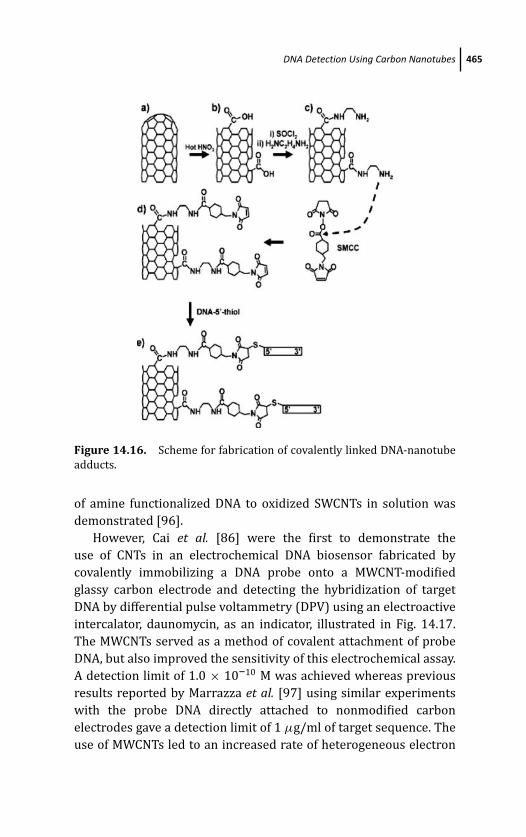
March 14, 2012 20:27 PSP Book - 9in x 6in 14-Ozsoz-c14
DNA Detection Using Carbon Nanotubes 465
Figure 14.16. Scheme for fabrication of covalently linked DNA-nanotube
adducts.
of amine functionalized DNA to oxidized SWCNTs in solution was
demonstrated [96].
However, Cai et al. [86] were the first to demonstrate the
use of CNTs in an electrochemical DNA biosensor fabricated by
covalently immobilizing a DNA probe onto a MWCNT-modified
glassy carbon electrode and detecting the hybridization of target
DNA by differential pulse voltammetry (DPV) using an electroactive
intercalator, daunomycin, as an indicator, illustrated in Fig. 14.17.
The MWCNTs served as a method of covalent attachment of probe
DNA, but also improved the sensitivity of this electrochemical assay.
A detection limit of 1.0 × 10⁻¹⁰ M was achieved whereas previous
results reported by Marrazza et al. [97] using similar experiments
with the probe DNA directly attached to nonmodified carbon
electrodes gave a detection limit of 1 μg/ml of target sequence. The
use of MWCNTs led to an increased rate of heterogeneous electron
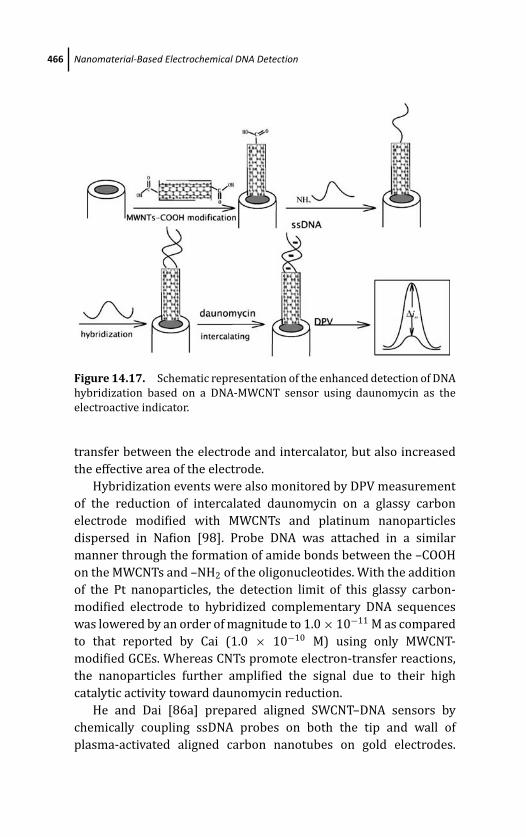
March 14, 2012 20:27 PSP Book - 9in x 6in 14-Ozsoz-c14
466 Nanomaterial-Based Electrochemical DNA Detection
Figure 14.17. Schematic representation of the enhanced detection of DNA
hybridization based on a DNA-MWCNT sensor using daunomycin as the
electroactive indicator.
transfer between the electrode and intercalator, but also increased
the effective area of the electrode.
Hybridization events were also monitored by DPV measurement
of the reduction of intercalated daunomycin on a glassy carbon
electrode modified with MWCNTs and platinum nanoparticles
dispersed in Nafion [98]. Probe DNA was attached in a similar
manner through the formation of amide bonds between the –COOH
on the MWCNTs and –NH2 of the oligonucleotides. With the addition
of the Pt nanoparticles, the detection limit of this glassy carbon-
modified electrode to hybridized complementary DNA sequences
was lowered by an order of magnitude to 1.0 × 10⁻¹¹ M as compared
to that reported by Cai (1.0 × 10⁻¹⁰ M) using only MWCNT-
modified GCEs. Whereas CNTs promote electron-transfer reactions,
the nanoparticles further amplified the signal due to their high
catalytic activity toward daunomycin reduction.
He and Dai [86a] prepared aligned SWCNT–DNA sensors by
chemically coupling ssDNA probes on both the tip and wall of
plasma-activated aligned carbon nanotubes on gold electrodes.
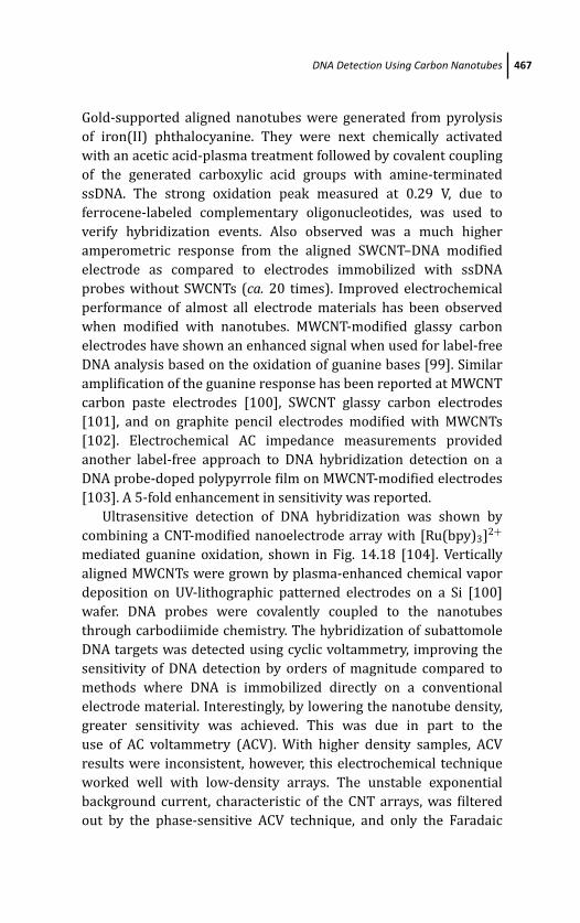
March 14, 2012 20:27 PSP Book - 9in x 6in 14-Ozsoz-c14
DNA Detection Using Carbon Nanotubes 467
Gold-supported aligned nanotubes were generated from pyrolysis
of iron(II) phthalocyanine. They were next chemically activated
with an acetic acid-plasma treatment followed by covalent coupling
of the generated carboxylic acid groups with amine-terminated
ssDNA. The strong oxidation peak measured at 0.29 V, due to
ferrocene-labeled complementary oligonucleotides, was used to
verify hybridization events. Also observed was a much higher
amperometric response from the aligned SWCNT–DNA modified
electrode as compared to electrodes immobilized with ssDNA
probes without SWCNTs (ca. 20 times). Improved electrochemical
performance of almost all electrode materials has been observed
when modified with nanotubes. MWCNT-modified glassy carbon
electrodes have shown an enhanced signal when used for label-free
DNA analysis based on the oxidation of guanine bases [99]. Similar
amplification of the guanine response has been reported at MWCNT
carbon paste electrodes [100], SWCNT glassy carbon electrodes
[101], and on graphite pencil electrodes modified with MWCNTs
[102]. Electrochemical AC impedance measurements provided
another label-free approach to DNA hybridization detection on a
DNA probe-doped polypyrrole film on MWCNT-modified electrodes
[103]. A 5-fold enhancement in sensitivity was reported.
Ultrasensitive detection of DNA hybridization was shown by
combining a CNT-modified nanoelectrode array with [Ru(bpy)3]2+
mediated guanine oxidation, shown in Fig. 14.18 [104]. Vertically
aligned MWCNTs were grown by plasma-enhanced chemical vapor
deposition on UV-lithographic patterned electrodes on a Si [100]
wafer. DNA probes were covalently coupled to the nanotubes
through carbodiimide chemistry. The hybridization of subattomole
DNA targets was detected using cyclic voltammetry, improving the
sensitivity of DNA detection by orders of magnitude compared to
methods where DNA is immobilized directly on a conventional
electrode material. Interestingly, by lowering the nanotube density,
greater sensitivity was achieved. This was due in part to the
use of AC voltammetry (ACV). With higher density samples, ACV
results were inconsistent, however, this electrochemical technique
worked well with low-density arrays. The unstable exponential
background current, characteristic of the CNT arrays, was filtered
out by the phase-sensitive ACV technique, and only the Faradaic
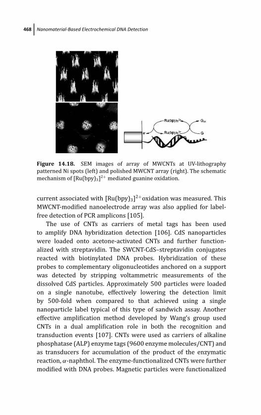
March 14, 2012 20:27 PSP Book - 9in x 6in 14-Ozsoz-c14
468 Nanomaterial-Based Electrochemical DNA Detection
Figure 14.18. SEM images of array of MWCNTs at UV-lithography
patterned Ni spots (left) and polished MWCNT array (right). The schematic
mechanism of [Ru(bpy)3]2+ mediated guanine oxidation.
current associated with [Ru(bpy)3]2+oxidation was measured. This
MWCNT-modified nanoelectrode array was also applied for label-
free detection of PCR amplicons [105].
The use of CNTs as carriers of metal tags has been used
to amplify DNA hybridization detection [106]. CdS nanoparticles
were loaded onto acetone-activated CNTs and further function-
alized with streptavidin. The SWCNT-CdS–streptavidin conjugates
reacted with biotinylated DNA probes. Hybridization of these
probes to complementary oligonucleotides anchored on a support
was detected by stripping voltammetric measurements of the
dissolved CdS particles. Approximately 500 particles were loaded
on a single nanotube, effectively lowering the detection limit
by 500-fold when compared to that achieved using a single
nanoparticle label typical of this type of sandwich assay. Another
effective amplification method developed by Wang’s group used
CNTs in a dual amplification role in both the recognition and
transduction events [107]. CNTs were used as carriers of alkaline
phosphatase (ALP) enzyme tags (9600 enzyme molecules/CNT) and
as transducers for accumulation of the product of the enzymatic
reaction, α-naphthol. The enzyme-functionalized CNTs were further
modified with DNA probes. Magnetic particles were functionalized
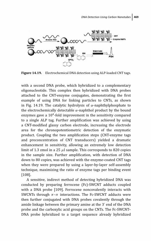
March 14, 2012 20:27 PSP Book - 9in x 6in 14-Ozsoz-c14
DNA Detection Using Carbon Nanotubes 469
Figure 14.19. Electrochemical DNA detection using ALP-loaded CNT tags.
with a second DNA probe, which hybridized to a complementary
oligonucleotide. This complex then hybridized with DNA probes
attached to the CNT-enzyme conjugates, demonstrating the first
example of using DNA for linking particles to CNTs, as shown
in Fig. 14.19. The catalytic hydrolysis of α-naphthylphosphate to
the electrochemically detectable α-naphthol product by the bound
enzymes gave a 104-fold improvement in the sensitivity compared
to a single ALP tag. Further amplification was achieved by using
a CNT-modified glassy carbon electrode, increasing the electrode
area for the chronopotentiometric detection of the enzymatic
product. Coupling the two amplification steps (CNT-enzyme tags
and preconcentration of CNT transducers) yielded a dramatic
enhancement in sensitivity, allowing an extremely low detection
limit of 1.3 zmol in a 25 μl sample. This corresponds to 820 copies
in the sample size. Further amplification, with detection of DNA
down to 80 copies, was achieved with the enzyme-coated CNT tags
when they were prepared by using a layer-by-layer self-assembly
technique, maximizing the ratio of enzyme tags per binding event
[108].
A sensitive, indirect method of detecting hybridized DNA was
conducted by preparing ferrocene (Fc)-SWCNT adducts coupled
with a DNA probe [109]. Ferrocene noncovalently interacts with
SWCNTs through π–π interactions. The Fc-SWCNT adducts were
then further conjugated with DNA probes covalently through the
amide linkage between the primary amine at the 3′ end of the DNA
probe and the carboxylic acid groups on the CNTs. The Fc-SWCNT–
DNA probe hybridized to a target sequence already hybridized
March 14, 2012 20:27 PSP Book - 9in x 6in 14-Ozsoz-c14
470 Nanomaterial-Based Electrochemical DNA Detection
to another DNA probe immobilized on a gold electrode. In this
sandwich assay the amplified electrochemical response was due to
the ferrocene-catalyzed reduction of H2O2.
14.4.3 Progress toward CNT-Based Sensors for DNADetection
The integration of CNTs into large-scale assemblies or circuits
requires precise control in the placement of the carbon nanotubes.
Several groups have used DNA to direct the assembly of CNTs
between metal electrodes to form a simple circuit. For example,
Hazani et al. [110] assembled a monolayer of probe thiol-terminated
ssDNA on two neighboring gold contacts. SWCNTs were modified
at the ends with complementary DNA sequences. Hybridization
between the complementary strands and the immobilized probes
resulted in bridging the gold contacts by the SWCNT. Current–
voltage (I –V ) curves were measured on electrode pairs using both
complementary and noncomplementary DNA-SWCNTs to bridge the
electrodes. The currents measured from the noncomplementary
interactions were an order of magnitude smaller compared to
currents measured from covalently bridged electrodes. Taft et al.[111] demonstrated that selective coupling of DNA to either the ends
or sidewalls of CNTs was highly specific and based on the DNA–CNT
linkage scheme. Either amine-terminated DNA was immobilized
on CNTs through free carboxyl groups, or pyrene-modified DNA
was immobilized noncovalently through hydrophobic interactions.
Complementary DNA was immobilized on gold particles and
hybridized with the CNT–DNA probes (covalently or noncovalently
attached). SEM images showed that the gold particles were bound
primarily at the ends of the CNTs when covalent functionalization
of probe DNA was used, or were located at the sidewalls when
probe DNA was attached noncovalently. Similarly, transmission
electron microscopy (TEM) was used to verify the binding of gold
nanoparticles modified with complementary strands of DNA to
probe DNA attached to SWCNTs [112]. Two methods for attaching
DNA to SWCNTs in either aqueous solution or in organic solvent
were developed and both methods resulted in selective attachment
of the DNA-modified gold particles at the tips of SWCNTs. These
methods for binding DNA provide versatility for modification of
March 14, 2012 20:27 PSP Book - 9in x 6in 14-Ozsoz-c14
DNA Detection Using Carbon Nanotubes 471
CNTS with DNA, but also demonstrate the potential for controlled
placement of nanotubes into sensors, FETs, or other electronic
devices. For practical device applications, the density of CNTs needs
consideration; an individual nanotube has a high risk of channel
failure. Baek et al. [113] recently demonstrated that the performance
of SWCNT devices for DNA hybridization was dependent on SWCNT
film density. SWCNT networks of varying density were deposited
onto glass slides. Using photolithography and reactive ion etching,
defined lines of SWCNT networks were patterned. Finally, using e-
beam lithography, metal evaporation of Co/Au was performed in
order to fabricate the final two-terminal device. Covalent attachment
of probe DNA via amide coupling to the SWCNT film spanning
the electrodes was conducted followed by complementary DNA
hybridization. The electrical behavior of hybridization at varying
film densities was determined from I –V curves and it was shown
that as the nanotube network density decreased, conductance
increased, with an optimum range of film density. This behavior is
likely due to an optimization in the number of reaction sites as well
as the conductance of the film.
SWCNTs were first used to fabricate FET devices in 1998 [114].
Since then several groups have fabricated CNTFETs, where absorbed
molecules that modulate the nanotube conductance replace the
solid-state gate. Only in the past few years have a small number
of research groups applied CNTFET devices for DNA detection.
DNA molecules can be selectively attached to either the nanotube
or at the metal electrodes. Hybridization of complementary DNA
at the nanotube is thought to mostly influence the electronic
response of the FET by electron depletion in the channel, whereas
binding at the electrodes modifies the metal work functions, that
is, the Schottky barrier [115]. Tang et al. [116] examined this
experimentally and found that the electrical conductance change,
observed when DNA hybridized to the device, was due to binding
at the gold electrodes instead of the sidewalls of the nanotube. Thus
the Schottky barrier modulation appeared to play a more significant
role in DNA detection. CNTFET devices have been fabricated using
peptide nucleic acid (PNA) oligonucleotides immobilized on the
gold surfaces [117]. Binding of complementary DNA resulted in an
increase in conductance corresponding to the increase in negative
surface charge density associated with binding of the negatively
March 14, 2012 20:27 PSP Book - 9in x 6in 14-Ozsoz-c14
472 Nanomaterial-Based Electrochemical DNA Detection
charged complementary DNA molecules. As a practical application,
an allele-specific assay was developed to detect the presence of
single nucleotide polymorphisms (SNPs) [91a]. A network of carbon
nanotubes within an FET device was functionalized with either
mutant or wild-type alleles while DNA hybridization to the corre-
sponding allele was measured through a decrease in conductance.
One last example is an amplification method reported in a CNTFET
device. As noted earlier, the incorporation of nanoparticles has been
shown to further enhance an electrochemical response of a CNT-
modified electrode [99]. Dong et al. [118] report on the use of a
SWCNTFET to detect target DNAs labeled with Au nanoparticles.
Hybridization events of CNT–DNA probes were detected down to
100 fM due to an increased conductivity through the NPs in close
proximity.
14.5 Conclusion
The integration of nanotechnology with biology and electrochem-
istry has produced many advances for novel DNA sensing strategies.
The ability to synthesize many nanomaterials in similar size
ranges to biomolecular markers makes their coupling with DNA
extremely efficacious toward the design of sensors to transduce
DNA hybridization events. Nanoparticles, nanorods, nanowires,
nanotubes, etc. have been used as labels in novel DNA detection
assays that are fast, sensitive, and reliable. Their use as supports
for DNA immobilization, tags that take advantage of their intrinsic
atomic make-up or ability to load and pre-concentrate secondary
labels, and ability to modulate interfacial phenomenon have been
described. Further advances are expected to lead to new generations
of electrochemical DNA sensors with implications in fields such as
medical diagnostics, drug discovery, detection of biothreats, and
environmental monitoring.
References
1. (a) J. Wang, Analyst 130, 421–426 (2005). (b) X. Mao and G. Liu,
J. Biomed. Nanotechnol. 4, 419–431 (2008). (c) M. Pumera, S. Sanchez,
I. Ichinose, and J. Tang, Sens. Actuators, B 123, 1195–1205 (2007). (d)
March 14, 2012 20:27 PSP Book - 9in x 6in 14-Ozsoz-c14
References 473
K. Kerman, M. Saito, S. Yamamura, Y. Takamura, and E. Tamiya, TrendsAnal. Chem, 27, 585–592 (2008).
2. (a) A. N. Shipway, E. Katz, and I. Willner, Chem. Phys. Chem. 1, 18–52
(2000). (b) J. Riu, A. Maroto, and F. X. Rius, Talanta 69, 288–301 (2006).
(c) R. Zhang and X. Wang, Chem. Mater. 19, 976–978 (2007). (d) S.
Guo, D. Wen, S. Dong, and E.Wang, Talanta 77, 1510–1517 (2009).(e)
S. N. Shtykov and T. Y. Rusanova, Russ. J. Gen. Chem. 78, 2521–2531
(2008).
3. S. J. Guo and S. J. Dong, TrAC-Trends Anal. Chem. 28, 96–109 (2009).
4. (a) E. Katz and I. Willner, Angew. Chem. Int. Ed. 43, 6042–6108 (2004).
(b) G. Schmid and L. F. Chi, Adv. Mat. 10, 515–526 (1998). (c) S. G. Kwon
and T. Hyeon, Acc. Chem. Res. 41, 1696–1709 (2008).
5. (a) C. A. Mirkin, R. L. Letsinger, R. C. Mucic, and J. J. Storhoff, Nature382, 607–609 (1996). (b) A. P. Alivisatos, K. P. Johnsson, X. G. Peng,
T. E. Wilson, C. J. Loweth, M. P. Bruchez Jr., and P. G. Schultz, Nature382, 609–611 (1996).
6. G. Martinez-Paredes, M. G. Gonzalez-Garcia, and A. Costa-Garcia,
Electroanalysis 21, 379–385 (2008).
7. S. F. Liu, Y. F. Li, J. R. Li, and L. Jiang, Biosens. Bioelec. 21, 789–795
(2005).
8. Y. Feng, T. Yang, W. Zhang, C. Jiang, and K. Jiao, Anal. Chim. Acta 616,
155–151 (2008).
9. J. H. Gao, H. W. Gu, and B. Xu, Acc. Chem. Res. 42, 1097–1107 (2009).
10. E. Palecek and M. Fojta, Talanta 74, 276–290 (2007).
11. X. Cai, G. Rivas, H. Shiraishi, P. Farias, J. Wang, M. Tomshik, F. Jelen, and
E. Palecek, Biosens. Bioelec. 344, 65–76 (1997).
12. J. Wang, A. N. Kawde, A. Erdem, and M. Salazar, Analyst 126, 2020–2024
(2001).
13. E. Palecek, S. Billova, L. Havran, R. Kizek, A. Miculkova, and F. Jelen,
Talanta 56, 919–930 (2002).
14. F. Jelen, B. Yosypchuk, A. Kourilova, L. Novotny, and E. Palecek, Anal.Chem. 74, 4788–4793 (2002).
15. S. Hason and V. Vetterl, Talanta 69, 572–580 (2006).
16. Y. Zhang, H. Ma, K. Zhang, S. Zhang, and J. Wang, Anal. Chim. Acta 54,
2385–2391 (2009).
17. H. Ma, L. Zhang, Y. Pan, K. Zhang, and Y. Zhang, Electroanalysis 20,
1220–1226 (2008).
18. Y. Zhang, K. Zhang, and H. Ma, 387, 13–19 (2009).

March 14, 2012 20:27 PSP Book - 9in x 6in 14-Ozsoz-c14
474 Nanomaterial-Based Electrochemical DNA Detection
19. M. B. Gonzalez-Garcia, C. Fernandez-Sanchez, and A. Costa-Garcia,
Biosens. Bioelectron. 15, 315–321 (2000).
20. L. Authier, C. Grossiord, P. Brossier, and B. Limoges, Anal. Chem. 73,
4450–4456 (2001).
21. J. Wang, D. Xu, A.-N. Kawde, and R. Polsky, Anal. Chem. 73, 5576–5581
(2001).
22. J. Wang, R. Polsky, and D. K. Xu, Langmuir 17, 5739–5741 (2001).
23. A.-N. Kawde and J. Wang, Electroanalysis 16, 101–107 (2004).
24. J. Wang, D. Xu, A.-N. Kawde, and R. Polsky, Anal. Chem. 73, 5576–5581
(2001).
25. J. Wang, G. D. Liu, R. Polsky, and A. Merkoci, Electrochem. Comm. 4, 722–
726 (2002).
26. J. Wang, G. D. Liu, and A. Merkoci, J. Am. Chem. Soc. 125, 3214–3215
(2003).
27. D. L. Escosura-Muniz, A. Ambrosi, and A. Merkoci, TrAC-Trends Anal.Chem. 27, 568–584 (2008).
28. M. Pumera, M. T. Castaneda, M. I. Pividori, R. Eritja, A. Merkoci, and
S. Alegret, Langmuir 21, 9625–9629 (2005).
29. M. T. Castaneda, A. Merkoci, M. Pumera, and S. Alegret, Biosens. Bioelec.22, 1961–1967 (2007).
30. K. Kerman, M. Saito, Y. Morita, Y. Takamura, M. Ozsoz, and E. Tamiya,
Anal. Chem. 76, 1877–1884 (2004).
31. G. D. Liu, T. M. Lee, and J. Wang, J. Am. Chem. Soc. 127, 38–39 (2005).
32. J. Zhang, B. P. Ting, N. R. Jana, Z. Gao, and J. Y. Ying, Small 5, 1414–1417
(2009).
33. B. P. Ting, J. Zhang, Z. Gao, and J. Y. Ying, Biosens. Bioelec. 25, 282–287
(2009).
34. J. Zhang, S. Song, L. Wang, H. Wu, D. Pan, and C. Fan, J. Am. Chem. Soc.128, 8575–8580 (2006).
35. H. Zhong, X. Li, X. Hun, and S. Zhang, Chem. Comm. 6058–6960 (2009).
36. G. Li, X. Li, J. Wan, and S. Zhang, Biosens. Bioelec. 24, 3281–3287 (2009).
37. R. Polsky, R. Gill, L. Kaganovsky, and I. Willner, Anal. Chem. 78, 2268–
2271 (2006).
38. J. Das, H. Kim, K. Jo, K.H. Park, S. Jon, K. Lee, and H. Yang, Chem. Comm.6394–6396 (2009).
39. F. Patolsky and C. Lieber, Materials Today 8, 20–28 (2005).
40. G. Cao and D. Liu, Adv. Colloid Interface Sci. 136, 45–64 (2008).

March 14, 2012 20:27 PSP Book - 9in x 6in 14-Ozsoz-c14
References 475
41. J. Wang, G. Liu, and Q. Zhu, Anal. Chem. 75, 6218–6222 (2003).
42. R. Gasparac, B. J. Taft, M. A. Lapierre-Devlin, A. D. Lazareck, J. M. Xu, and
S. O. Kelley, J. Am. Chem. Soc. 126, 12270–12271 (2004).
43. M. A. Lapierre-Devlin, C. L. Asher, B. J. Taft, R. Gasparac, M. A. Roberts,
and S. O. Kelley, Nano Lett. 5, 1051–1055 (2005).
44. Z. Fang and S. O. Kelley, Anal. Chem. 81, 612–617 (2009).
45. A. Andreu, J. W. Merkert, L. A. Lecaros, B. L. Broglin, J. T. Brazell, and
M. El-Kouedi, Sens. Actuators B: Chem. 114, 1116–1120 (2006).
46. A. Steele, T. Herne, and M. Tarlov, Anal. Chem. 70, 4670–4677 (1998).
47. N. Zhu, Z. Chang, P. He, and Y. Fang, Electrochim. Acta 51, 3758–3762
(2006).
48. H. Chang, Y. Yuan, N. Shi, and Y. Guan, Anal. Chem. 79, 5111–5115
(2007).
49. N. Yang, H. Uetsuka, E. Osawa, and C. E. Nebel, Angew. Chem. Int. Ed. 47,
5183–5185 (2008).
50. J. Hahm and C. M. Lieber, Nano Lett. 4, 51–54 (2004).
51. Z. Li, Y. Chen, X. Li, T. I. Kamins, K. Nauka, and R. S. Williams, Nano Lett.4, 245–247 (2004).
52. Z. Gao, A. Agarwal, A. D. Trigg, N. Singh, C. Fang, C.-H. Tung, Y. Fan, K. D.
Buddharaju, and J. Kong, J. Anal. Chem. 79, 3291–3297 (2007).
53. X. Wang and C. S. Ozkan, Nano Lett. 8, 398–404 (2008).
54. J. Kong, A. R. Ferhan, X. Chen, L. Zhang, and N. Balasubramanian, Anal.Chem. 80, 7213–7217 (2008).
55. J. Wang, O. Rincon, R. Polsky, and E. Dominguez, Electrochem. Commun.5, 83–86 (2003).
56. C. Chen, A. Ganguly, C.-H. Wang, C.-W. Hsu, S. Chattopadhyay, Y.-K. Hsu,
Y.-C. Chang, K.-H. Chen, and L.-C. Chen, Anal. Chem. 81, 36–42 (2009).
57. A. W. Bosman, H. M. Janssen, and E. W. Meijer, Chem. Rev. 99, 1665–
1688 (1999).
58. N. Zhu, H. Gao, Y. Gu, Q. Xu, P. He, and Y. Fang, Analyst 134, 860–866
(2009).
59. M. Humenik, C. Pohlmann, Y. Wang, and M. Sprinzl, Bioconjugate Chem.19, 2456–2461 (2008).
60. N. Zhu, Y. Gu, Z. Chang, P. He, and Y. Fang, Electroanalysis 18, 2107–2114
(2006).
61. A. Li, F. Yang, Y. Ma, and X. Yang, Biosens. Bioelectron. 22, 1716–1722
(2007).
March 14, 2012 20:27 PSP Book - 9in x 6in 14-Ozsoz-c14
476 Nanomaterial-Based Electrochemical DNA Detection
62. E. Kim, K. Kim, H. Yang, Y. T. Kim, and J. Kwak, Anal. Chem. 75, 5665–
5672 (2003).
63. J. M. Gibbs, S.-J. Park, D. R. Anderson, K. J. Watson, C. A. Mirkin, and S. T.
Nguyen, J. Am. Chem. Soc. 127, 1170–1178 (2006).
64. F. Wei, W. Liao, Z. Xu, Y. Yang, D. T. Wong, and C.-M. Ho, Small 5, 1784–
1790 (2009).
65. G. C. Ford, P. M. Harrison, D. W. Rice, J. M. A. Smith, A. Treffry, Y. J. White,
and J. Yariv, Philos. Trans. R. Soc. London Ser. B 304, 551–565 (1984).
66. X. Mao and G. Liu, J. Biomed. Nanotechnol. 4, 419–431 (2008).
67. G. Liu, H. Wu, A. Dohnalkova, and Y. Lin, Anal. Chem. 79, 5614–5619
(2007).
68. G. Liu, J. Wang, S. A. Lea, and Y. Lin, Chem. BioChem. 7, 1315–1319
(2006).
69. G. Liu and Y. Lin, J. Am. Chem. Soc., 129, 10394–10401 (2007).
70. N. Zhu, H. Cai, P. He, and Y. Fang, Anal. Chim. Acta 481, 181–189 (2003).
71. Y. Ma, K. Jiao, T. Yang, and D. Sun, Sens. Actuators B: Chem. 131, 565–571
(2008).
72. D. Zhang, Y. Chen, H.-Y. Chen, and X. H. Xia, Anal. Bioanal. Chem. 379,
1025–1030 (2004).
73. F. Patolsky, A. Lichtenstein, and I. Willner, Angew. Chem. Int. Ed. 39,
940–943 (2000).
74. L. Alfonta, A. K. Singh, and I. Willner, Anal. Chem. 73, 91–102 (2001).
75. F. Patolsky, A. Lichtenstein, and I. Willner, J. Am. Chem. Soc. 123, 5194–
5205 (2001).
76. V. N. Goral, N. V. Zaytseva, and A. J. Baeumner, Lab Chip 6, 414–421
(2006).
77. S. R. Nugen, P. J. Asiello, J. T. Connelly, and A. J. Baeumner, Biosens.Bioelectron. 24, 2428–2433 (2009).
78. W.-C. Liao and J. A. Ho, Anal. Chem., 81, 2470–2476 (2009).
79. M. S. Dresselhaus, G. Dresselhaus, and P. Avouris, Carbon Nanotubes:Synthesis, Properties and Applications, Springer, Berlin (2001).
80. S. Iijima, Nature 354, 56–58 (1991).
81. (a) S. Iijima and T. Ichihashi, Nature 363, 603–605 (1993). (b) D. S.
Bethune, C. H. Kiang, M. S. de Vries, G. Gorman, R. Savoy, J. Vazquez, and
R. Beyers, Nature 363, 605–607 (1993).
82. (a) J. Wang and Y. Lin, Trends Anal. Chem. 27(7), 619–626 (2008).
(b) B. L. Allen, P. D. Kichambare, and A. Star, Adv. Mater. 19, 1439–
March 14, 2012 20:27 PSP Book - 9in x 6in 14-Ozsoz-c14
References 477
1451 (2007). (c) S. N. Kim, J. F. Rusling, and F. Papadimitrakopoulos,
Adv. Mater. 19, 3214–3228 (2007). (d) E. Katz and I. Willner,
ChemPhysChem 5, 1084–1104 (2004).
83. (a) G. Sanchez-Pomales, L. Santiago-Rodrıguez, and C. R. Cabrera,
J. Nanosci Nanotechnol. 9, 2175–2188 (2009). (b) S. Daniel, T. P. Rao,
K. S. Rao, S. U. Rani, G. R. K. Naidu, H. Y. Lee, and T. Kawai, Sens.Actuators, B 122, 672–682 (2007).
84. (a) D.-H. Jung, B. H. Kim, Y. K. Ko, M. S. Jung, S. Jung, S. Y. Lee, and
H.-T. Jung, Langmuir 20, 8886–8891 (2004). (b) Y.-Z. You, C.-Y. Hong,
and C.-Y. Pan, J. Phys. Chem. C 111, 16161–16166 (2007). (c) C. Cao,
J. H. Kim, D. Yoon, E.-S. Hwang, Y.-J. Kim, and S. Baik, Mater. Chem. Phys.112, 738–741 (2008). (d) M. L. Usrey, N. Nair, D. E. Agnew, C. F. Pina,
and M. S. Strano, Langmuir 23, 7768–7776 (2007).
85. (a) P. He and L. Dai, Chem. Comm, 3, 348–349 (2004). (b) K. A. Williams,
P. T. M. Veenhuizen, B. G. de la Torre, R. Eritja, and C. Dekker, Nature420, 761–762 (2002). (c) W. Chen, C. H. Tzang, J. Tang, M. Yang, and S. T.
Lee, Appl. Phys. Lett. 86, 103114–5 (2005). (d) J. Li, H. T. Ng, A. Cassell,
W. Fan, H. Chen, Q. Ye, J. Koehne, J. Han, and M. Meyyappan, Nano Lett. 3,
597–602 (2003). (e) J. Koehne, H. Chen, J. Li, A. M. Cassell, Q. Ye, H. T. Ng,
J. Han, and M. Meyyappan, Nanotechnology 14, 1239–1245 (2003). (f)
M. Hazani, F. Hennrich, M. Kappes, R. Naaman, D. Peled, V. Sidorov, and
D. Shvarts, Chem. Phys. Lett. 391, 389–392 (2004). (g) H. Cai, X. Cao,
Y. Jiang, P. He, and Y. Fang, Anal. Bioanal. Chem. 375, 287–293 (2003).
86. (a) P. Singh, S. Campidelli, S. Giordani, D. Bonifazi, A. Biancoa, and
M. Prato, Chem. Soc. Rev. 38, 2214–2230 (2009). (b) K. Balasubra-
manian and M. Burghard, Small 1, 180–192 (2005).
87. M. J. Moghaddam, S. Taylor, M. Gao, S. Huang, L. Dai, and M. J. McCall,
Nano Lett. 4, 89–93 (2004).
88. (a) S. C. Tsang, Z. Guo, Y. K. Chen, M. L. H. Green, H. A. O. Hill, T. W.
Hambley, and P. J. Sadler, Angew. Chem. Int. Ed. Engl, 36, 2198–2200
(1997). (b) Z. Guo, P. J. Sadler, and S. C. Tsang, Adv. Mater. 10, 701–703
(1998). (c) R. J. Chen, Y. Zhang, D. Wang, and H. Dai, J. Am. Chem. Soc.123, 3838–3839 (2001). (d) M. Shim, N. W. S. Kam, R. J. Chen, Y. Li., and
H. Dai, Nano Lett, 2, 285–288 (2002).
89. (a) A. Star, E. Tu, J. Niemann, J.-C. P. Gabriel, C. S. Joiner, and C. Valcke, in
Proc. Natl. Acad. Sci. U.S.A. 103, 921–926 (2006). (b) E.-L. Gui, L.-J. Li,
P. S. Lee, A. Lohani, S. G. Mhaisalkar, Q. Cao, S. J. Kang, J. A. Rogers, N. C.
Tansil, and Z. Gao, Appl. Phys. Lett. 89, 232104-232104-3 (2006). (c) E.
L. Gui, L. Li, K. Zhang, Y. Xu, X. Dong, A. Ho, P. S. Lee, J. Kasim, Z. X. Shen,
March 14, 2012 20:27 PSP Book - 9in x 6in 14-Ozsoz-c14
478 Nanomaterial-Based Electrochemical DNA Detection
J. A. Rogers, and S. G. Mhaisalkar, J. Am. Chem. Soc. 129, 14427–14432
(2007).
90. M. Zheng, A. Jagota, E. D. Semke, B. A. Diner, R. S. Mclean, S. R. Lustig,
R. E. Richardson, and N. G. Tassi, Nat. Mater. 2, 338–342 (2003).
91. M. Zheng, A. Jagota, M. S. Strano, A. P. Santos, P. Barone, S. G. Chou, B. A.
Diner, et al., Science 302, 1545–1548 (2003).
92. T. Ito, L. Sun, and R. M. Crooks, Chem. Commun. 1482–1483 (2003).
93. J. Wang, M. Li, Z. Shi, N. Li, and Z. Gua, Electroanalysis 16, 140–144
(2004).
94. M. Guo, J. Chen, D. Liu, L. Nie, and S. Yao, Bioelectrochemistry 62, 29–35
(2004).
95. S. E. Baker, W. Cai, T. L. Lasseter, K. P. Weidkamp, and R. J. Hamers, NanoLett. 2, 1413–1417 (2002).
96. (a) C. Dwyer, M. Guthold, M. Falvo, S. Washburn, R. Superfine, and
D. Erie, Nanotechnology 13, 601–604 (2002). (b) M. Hazani, R. Naaman,
F. Hennrich, and M. M. Kappes, Nano Lett. 3, 153–155 (2003).
97. G. Marrazza, I. Chianella, and M. Mascini, Biosens. Bioelectron. 14, 43–
51 (1999).
98. N. Zhu, Z. Chang, P. He, and Y. Fang, Anal. Chim. Acta 545, 21–26 (2005).
99. J. Wang, A. Kawde, and M. Mustafa, Analyst 128, 912–916 (2003).
100. (a) K. Kerman, Y. Morita, Y. Takamura, M. Ozsoz, and E. Tamiya,
Electroanalysis 16, 1667–1672 (2004). (b) M. Pedano and G. A. Rivas,
Electrochem. Commun. 6, 10–16 (2004).
101. J. Wang, M. Li, Z. Shi, N. Li, and Z. Gu, Electroanalysis 16, 140–144
(2004).
102. A. Erdem, P. Papakonstantinou, and H. Murphy, Anal. Chem. 78, 6656–
6659 (2006).
103. H. Cai, Y. Xu, P.-G. He, and Y.-Z. Fang, Electroanalysis 15, 1864–1870
(2003).
104. J. Li, H. T. Ng, A. Cassell, W. Fan, H. Chen, Q. Ye, J. Koehne, J. Han, and
M. Meyyappan, Nano Lett. 3, 597–602 (2003).
105. J. Koehne, H. Chen, J. Li, A. M. Cassell, Q. Ye, H. T. Ng, J. Han, and
M. Meyyappan, Nanotechnology, 14, 1239–1245 (2003).
106. J. Wang, G. Liu, M. R. Jan, and Q. Zhu, Electrochem. Commun. 5, 1000–
1004 (2003).
107. J. Wang, G. D. Liu, and M. R. Jan, J. Am. Chem. Soc. 126, 3010–3011
(2004).
March 14, 2012 20:27 PSP Book - 9in x 6in 14-Ozsoz-c14
References 479
108. B. Munge, G. Liu, G. Collins, and J. Wang, Anal. Chem. 77, 4662–4666
(2005).
109. X. Yang, Y. Lu, Y. Ma, Z. Liu, F. Du, and Y. Chen, Biotechnol. Lett. 29, 1775–
1779 (2007).
110. M. Hazani, F. Hennrich, M. Kappes, R. Naaman, D. Peled, V. Sidorov, and
D. Shvarts, Chem. Phys. Lett. 391, 389–392 (2004).
111. B. J. Taft, A. D. Lazareck, G. D. Withey, A. Yin, J. M. Xu, and S. O. Kelley,
J. Am. Chem. Soc. 126, 12750–12751 (2004).
112. W. Yang, M. J. Moghaddam, S. Taylor, B. Bojarski, L. Wieczorek,
J. Herrmann, and M. J. McCall, Chem. Phys. Lett. 443, 169–172 (2007).
113. Y.-K. Baek, S. M. Yoo, J.-H. Kim, D.-H. Jung, Y.-K. Choi, Y. S. Kim, S. Y. Lee,
and H.-T. Jung, J. Phys. Chem. C 113, 21566–21571 (2009).
114. S. J. Tans, A. R. M. Verschueren, and C. Dekker, Nature 393, 49–52
(1998).
115. (a) T. Nakanishi, A. Bachtold, and C. Dekker, Phys. Rev. B 66, 073307-
073307-4 (2002). (b) M. Freitag, A. T. Johnson, S. Kalinin, and
D. Bonnell, Phys. Rev. Lett. 89, 216 801-216 801-4 (2002).
116. X. Tang, S. Bangsaruntip, N. Nakayama, E. Yenilmez, Y. I. Chang, and
Q. Wang, Nano Lett. 6, 1632–1636 (2006).
117. K. Maehashi, K. Matsumoto, K. Kerman, Y. Takamura, and E. Tamiya, Jpn.J. Appl. Phys. 43, L1558-L1560 (2004).
118. X. Dong, C. M. Lau, A. Lohani, S. G. Mhaisalkar, J. Kasim, Z. Shen, X. Ho,
J.A. Rogers, and L.-J. Li, Adv. Mater. 20, 2389–2393 (2008).

This page intentionally left blankThis page intentionally left blank
March 20, 2012 9:44 PSP Book - 9in x 6in 15-Ozsoz-c15
Chapter 15
Electrochemical Genosensor Assay forthe Detection of Bacteria onScreen-Printed Chips
Chan Yean Yeana*, Lee Su Yinb, and Manickam Ravichandranb
aDepartment of Medical Microbiology and Parasitology, School of Medical Sciences,Universiti Sains Malaysia, Kota Bharu, MalaysiabFaculty of Applied Sciences, AIMST University, 08100 Semeling, Kedah, Malaysia*[email protected]
Electrochemical genosensors for the detection of bacteria were
introduced about a decade ago. Miniaturization and advanced
microfabrication technology have made it compatible with bacteria
DNA diagnostic. This technology is cost effective, fast, and accurate.
The bioaffinity and biocatalysis reactions generate amperometric,
voltametric, impedimetric, or conductimetric signals on screen-
printed transducer chips (SPC), which is proportional to the number
of immobilized DNA copies on the SPC surface. Electrochemical
genosensor assays give quantitative rather than qualitative results.
Furthermore, the use of a hand-held portable reader makes this
assay suitable for use in the field, especially for point-of-care (POC)
tests at the patient bedside, during surveillance and environmental
studies of microorganisms.
Electrochemical DNA BiosensorsEdited by Mehmet OzsozCopyright c© 2012 Pan Stanford Publishing Pte. Ltd.ISBN 978-981-4241-77-9 (Hardcover), 978-981-4303-98-9 (eBook)www.panstanford.com
March 20, 2012 9:44 PSP Book - 9in x 6in 15-Ozsoz-c15
482 Electrochemical Genosensor Assay for the Detection of Bacteria on Screen-Printed Chips
15.1 Introduction
In clinically and epidemiologically severe infectious diseases, the
rapid identification and detection of the causative organism is
crucial for effective control, management, and prompt treatment of
the infection. The conventional laboratory methods involve culture,
microscopy, and biochemical tests [1]. This process is laborious and
takes 2 to 4 days or longer to obtain a result. Culture methods often
lack sensitivity, especially for poorly handled samples or clinical
samples from patients previously treated with antibiotics [2].
Polymerase chain reaction (PCR) has been used extensively
as a diagnostic tool in various fields, such as genetic screening,
infectious disease diagnosis, forensics, environmental monitoring,
and veterinary science. PCR is an enzymatic process in which
specific regions of DNA are amplified in vitro. This process amplifies
the target DNA exponentially to generate billions of copies from
a single copy in less than 1 h [3]. The conventional detection of
PCR amplicons by electrophoresis exposes the user to hazardous
chemicals, such as ethidium bromide and ultraviolet light. Other
safer detection techniques, such as capillary blotting and enzyme-
linked immunoassays, require multiple hybridization and washing
steps, which are labor-intensive and time consuming.
15.2 Methods for the Detection and Identification ofMicroorganism Utilizing Enzyme-Based Genosensorson Screen-Printed Chips
15.2.1 Electrochemical Genosensors for the Detection ofBacteria
Electrochemical genosensors for the detection of bacteria were
introduced about a decade ago. Miniaturization and advanced
microfabrication technology have made it compatible with bacteria
DNA diagnostic. This technology is cost effective, fast, and accurate.
The bioaffinity and biocatalysis reactions generate either amper-
ometric, voltametric, impedimetric, or conductimetric signals on
screen-printed transducer chips (SPC), which is proportional to the
number of immobilized DNA copies on the SPC surface.
March 20, 2012 9:44 PSP Book - 9in x 6in 15-Ozsoz-c15
Methods for the Detection and Identification of Microorganism 483
Electrochemical methods are well suited for molecular diagnos-
tics of microorganisms on the genomic and proteomic level. Electro-
chemical reactions can be designed to produce a direct electronic
signal using a portable handheld and inexpensive electrochemical
analyzer (AndCare, PalmSens, DropSens etc.) that is commercially
available in the market, without any expensive signal transduction
equipment [4].
Numerous electrochemical platforms have been developed for
DNA detection, including direct electrochemistry of the DNA
bases [5], electrochemistry of different polymer-modified screen-
printed chips [6], electrochemistry of DNA-specific redox indicator
molecules or enzymes [7, 8], electrochemistry of signal amplification
with nanoparticles (NPs) such as gold, silver or magnetic particles
[9, 10], and dsDNA π -stacked mediated charge transport chemistry
[4, 7, 11, 12].
A genosensor for bacterial detection should possess the fol-
lowing criteria: sensitive (able to detect the bacterium in a small
sample), specific (able to distinguish the target from non-target
strains), precise, rapid and able to perform direct measurement
without pre-enrichment. In addition, it would be desirable if
the genosensor is portable or handheld, affordable and can be
performed even by untrained personnel.
Biosensors for bacterial detection involve biological recognition
components such as presence of the biomarkers, nucleic acid,
antibodies or aptamer attached on a transducer. However, in this
chapter, bacterial nucleic acid will be described in detail [13].
Electrochemical genosensors for detection of various bacterial
species have been described in Refs. 8 and 13–19. Reliable detection
assays have been developed for pathogenic bacteria such as
Salmonella sp, E. coli 0157:H7, Staphylococcus aureus and Vibriocholerae that cause major worldwide foodborne outbreaks [8, 13, 16,
19, 20].
The general scheme of a genosensor assay development starts
with the immobilization of the specific nucleic acid sequence
(“probe”) on the transducer surface. The presence of the com-
plementary sequence (“target”) in the sample is recognized and
captured by the probe through hybridization.
March 20, 2012 9:44 PSP Book - 9in x 6in 15-Ozsoz-c15
484 Electrochemical Genosensor Assay for the Detection of Bacteria on Screen-Printed Chips
A probe is an oligonucleotide (single stranded DNA or RNA)
with the size of 18 to 25 bases. The difference between probe and
primer is the function of the oligonucleotide. Primer is used during
polymerase chain reaction (PCR); however probe is used during
capturing of the target DNA during hybridization.
Short single-stranded synthetic targets (∼20–60 bases oligonu-
cleotides) are used to evaluate the technology platform and
specificity of the DNA sequences in identification of bacteria before
the assay is evaluated with PCR amplicons.
The DNA duplex formation can be detected based on the
incorporation or association of a hybridization indicator or changes
accrued from the hybridization event. Different indicators can be
used in detection of DNA based on the appropriate electrochemical
activity selected, it can be either label-free (e.g. guanine, adenine),
or label-based (enzyme-based, ferrous and ferricyanide, Ruthenium
bipyridine [Ru (bpy)], methylene blue, Ethidium bromide etc).
The hybridization event is detected via the increase or decrease
in signal of the redox indicator or changes in conductivity or
impedance/capacitance.
Most genosensors are designed to detect bacterial DNA that
is first amplified by PCR. The species-specific detection of the
bacteria mainly depends on hybridization of the specific probes to
complementary sequences in the PCR amplicons. PCR primers and
hybridization probes are designed using bioinformatic softwares
to ensure high specificity and sensitivity. The bacterial genetic
sequences can be obtained from GenBank of National Center
for Biotechnology Information (NCBI) (www.ncbi.nlm.nih.gov). The
target genes selected will depend on the purpose of the test,
either for identification of infectious bacteria, detection of antibiotic
resistant genotypes (MRSA, VRE, ESBL), bioterrorism (anthrax,
Burkholderia pseudomallei or melioidosis, Yersinia pestis or plague),
food pathogens (V. cholerae, Clostridium botulinum, Escherichia coli0157:H7), fecal contamination (Enterococcus species) or environ-
mental surveillance. Then target gene sequences will be down-
loaded from Genbank and aligned by multiple sequence alignment
softwares available such as VectorNTI (Invitrogen Corporation,
California, USA). The highly specific gene regions (conserved
regions) will be selected for primer designing.
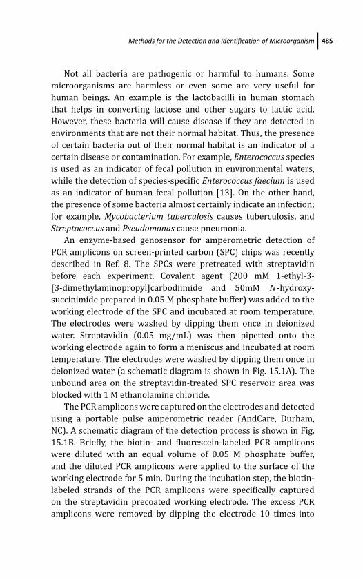
March 20, 2012 9:44 PSP Book - 9in x 6in 15-Ozsoz-c15
Methods for the Detection and Identification of Microorganism 485
Not all bacteria are pathogenic or harmful to humans. Some
microorganisms are harmless or even some are very useful for
human beings. An example is the lactobacilli in human stomach
that helps in converting lactose and other sugars to lactic acid.
However, these bacteria will cause disease if they are detected in
environments that are not their normal habitat. Thus, the presence
of certain bacteria out of their normal habitat is an indicator of a
certain disease or contamination. For example, Enterococcus species
is used as an indicator of fecal pollution in environmental waters,
while the detection of species-specific Enterococcus faecium is used
as an indicator of human fecal pollution [13]. On the other hand,
the presence of some bacteria almost certainly indicate an infection;
for example, Mycobacterium tuberculosis causes tuberculosis, and
Streptococcus and Pseudomonas cause pneumonia.
An enzyme-based genosensor for amperometric detection of
PCR amplicons on screen-printed carbon (SPC) chips was recently
described in Ref. 8. The SPCs were pretreated with streptavidin
before each experiment. Covalent agent (200 mM 1-ethyl-3-
[3-dimethylaminopropyl]carbodiimide and 50mM N -hydroxy-
succinimide prepared in 0.05 M phosphate buffer) was added to the
working electrode of the SPC and incubated at room temperature.
The electrodes were washed by dipping them once in deionized
water. Streptavidin (0.05 mg/mL) was then pipetted onto the
working electrode again to form a meniscus and incubated at room
temperature. The electrodes were washed by dipping them once in
deionized water (a schematic diagram is shown in Fig. 15.1A). The
unbound area on the streptavidin-treated SPC reservoir area was
blocked with 1 M ethanolamine chloride.
The PCR amplicons were captured on the electrodes and detected
using a portable pulse amperometric reader (AndCare, Durham,
NC). A schematic diagram of the detection process is shown in Fig.
15.1B. Briefly, the biotin- and fluorescein-labeled PCR amplicons
were diluted with an equal volume of 0.05 M phosphate buffer,
and the diluted PCR amplicons were applied to the surface of the
working electrode for 5 min. During the incubation step, the biotin-
labeled strands of the PCR amplicons were specifically captured
on the streptavidin precoated working electrode. The excess PCR
amplicons were removed by dipping the electrode 10 times into
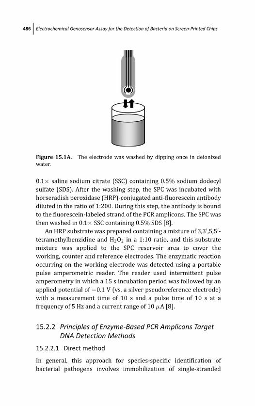
March 20, 2012 9:44 PSP Book - 9in x 6in 15-Ozsoz-c15
486 Electrochemical Genosensor Assay for the Detection of Bacteria on Screen-Printed Chips
Figure 15.1A. The electrode was washed by dipping once in deionized
water.
0.1× saline sodium citrate (SSC) containing 0.5% sodium dodecyl
sulfate (SDS). After the washing step, the SPC was incubated with
horseradish peroxidase (HRP)-conjugated anti-fluorescein antibody
diluted in the ratio of 1:200. During this step, the antibody is bound
to the fluorescein-labeled strand of the PCR amplicons. The SPC was
then washed in 0.1× SSC containing 0.5% SDS [8].
An HRP substrate was prepared containing a mixture of 3,3′,5,5′-tetramethylbenzidine and H2O2 in a 1:10 ratio, and this substrate
mixture was applied to the SPC reservoir area to cover the
working, counter and reference electrodes. The enzymatic reaction
occurring on the working electrode was detected using a portable
pulse amperometric reader. The reader used intermittent pulse
amperometry in which a 15 s incubation period was followed by an
applied potential of −0.1 V (vs. a silver pseudoreference electrode)
with a measurement time of 10 s and a pulse time of 10 s at a
frequency of 5 Hz and a current range of 10 μA [8].
15.2.2 Principles of Enzyme-Based PCR Amplicons TargetDNA Detection Methods
15.2.2.1 Direct method
In general, this approach for species-specific identification of
bacterial pathogens involves immobilization of single-stranded
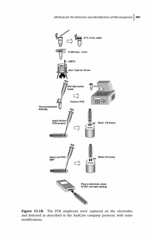
March 20, 2012 9:44 PSP Book - 9in x 6in 15-Ozsoz-c15
Methods for the Detection and Identification of Microorganism 487
Figure 15.1B. The PCR amplicons were captured on the electrodes
and detected as described in the AndCare company protocol, with some
modifications.
March 20, 2012 9:44 PSP Book - 9in x 6in 15-Ozsoz-c15
488 Electrochemical Genosensor Assay for the Detection of Bacteria on Screen-Printed Chips
oligonucleotide capture probes onto the transducer surface and
hybridization of single-stranded oligonucleotide target which is
labeled with haptens (biotin, fluorescent, digoxigenin, etc.) on one
end during PCR. Thus, this method can only be applied on PCR
amplicons that are labeled with haptens on one end. The two-
component complex on the transducer surface will enable binding
of a specific anti-hapten-conjugated HRP or alkaline phosphatase
(AP) reporter enzyme to the probes-target complex. Addition of the
enzyme-specific redox substrate and application of a fixed potential
between working and reference electrodes on the transducer
surface generates an enzyme-mediated redox cycle and detected
in the form of a current (Fig. 15.2A). The electroredox current
amplitude reveals the concentration of the probe-target complexes.
15.2.2.2 Indirect method
This approach for species-specific identification of bacterial
pathogens involves immobilization of a single-stranded oligonu-
cleotide capture probe onto the transducer surface, followed by
hybridization of single-stranded oligonucleotide targets and a
detection probe which is labeled with haptens (biotin, fluorescent,
digoxigenin, etc.) on one end. This method can be performed even
without labeling the PCR amplicons. The detection of the three-
component “sandwich” complex (capture probes-target-detection
probes) on the transducer surface is the same as using the direct
method (Fig 15.2B).
15.2.2.3 Rapid method
In this approach double-stranded oligonucleotide PCR amplicons
are labeled with a hapten on one end and another different hapten
on the other end during PCR. The transducer surface (gold or carbon
screen-printed chips) is treated with protein based anti-haptens
that capture one of the hapten label on the PCR amplicons. The
second hapten label on the PCR amplicons will bind to a specific
anti-hapten-conjugated HRP or AP reporter enzyme to labeled PCR
amplicons. Addition of the enzyme-specific redox substrate and
application of a fixed potential between working and reference
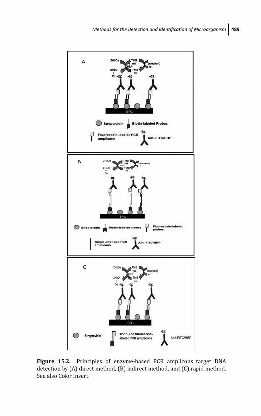
March 20, 2012 9:44 PSP Book - 9in x 6in 15-Ozsoz-c15
Methods for the Detection and Identification of Microorganism 489
Figure 15.2. Principles of enzyme-based PCR amplicons target DNA
detection by (A) direct method, (B) indirect method, and (C) rapid method.
See also Color Insert.
March 20, 2012 9:44 PSP Book - 9in x 6in 15-Ozsoz-c15
490 Electrochemical Genosensor Assay for the Detection of Bacteria on Screen-Printed Chips
electrodes on the transducer surface generates an enzyme-mediated
redox cycle and detected in the form of current (Fig. 15.2C). The
electroredox current amplitude reveals the concentration of the
labeled PCR amplicons in the test sample.
15.2.3 Screen-Printed Transducer Surface
The surface structure and chemistry of electrochemical transducers
with regard to the detection of DNA hybridization and electron
transfer (current measurement) have been thoroughly investi-
gated in several studies [13, 21–23]. The immobilization of the
oligonucleotide probe onto the transducer surface will influence the
genosensor performance. The oligonucleotide probe orientation on
the surface will determine the accessibility of the probe to target
DNA. The type of probe, either labeled or unlabeled will depend
on the transducer surface used. For example, on the screen-printed
carbon electrode, the immobilization method of the oligonucleotide
probe on the surface can be either covalent bonding, adsorption
or electrostatic by applying a fixed potential between working and
reference electrodes on the transducer surface.
15.2.3.1 Screen-printed gold chip genosensors
In recent electrochemical genosensor studies, researchers have
started using screen-printed gold chips and modified thiolated
oligonucleotide probe to form a self assembly monolayer on the
chip’s surface. There are many ways to detect the hybridization
of the probe and target DNA, such as enzyme-based (HRP or
AP) or label-free oxidation of guanine bases, anthraquinone-2,6-
disulfonic acid (AQDS) anthraquinone-2-monoisulfonic acid (AQMS)
methylene blue, Ruthenium bipyridine [Ru(bpy)], hexaamineruthe-
nium(III) chloride or ferrocene.
However, on the screen-printed gold electrode, the self-assembly
immobilization of the oligonucleotide probe on the gold surface,
the probe can be either 3’-thiol or 5’-thiol labeled with C3 or C6
linker depending on the signal substances [such as AQMS, enzyme,
MB, Ru (bpy), ferrocene] and the blocking agent used [2-Mercapto-
1-ethanol (MCE), 6-mercapto-1-hexanol (MCH) or 11-mercapto-1-
March 20, 2012 9:44 PSP Book - 9in x 6in 15-Ozsoz-c15
Methods for the Detection and Identification of Microorganism 491
undecanol). The usage of the different carbon linkers (C3 or C6)
and blocking agents (MCE MCH or MCU) are based on the different
biosensor requirements [12].
A few examples of pathogen detection using enzyme-based
electrochemical genosensors have been developed [8, 13–19]. In
addition, Farabullini et al. (2007) and Liao et al. (2006) published
their microfabrication of simultaneous detection of different food
pathogenic bacteria (Salmonella species, Lysteria monocytogenes,
Staphylococcus aureus and Escherichia coli) and uropathogens
(Escherichia coli, Proteus mirabilis, Pseudomonas aeruginosa,Enterococcus species, Klebsiella species, Enterobacter species andthe Enterobacteriaceae group) in clinical urine specimens by means
of a disposable electrochemical gold genosensor array.
These analytical methods relied on the immobilization of
specific-thiolated probes with the optimized concentration on the
screen-printed arrays of gold electrodes. The unlabeled or unmodi-
fied PCR amplicons from the bacteria genomic DNA were captured
onto the capture probes on the transducer surface via sandwich
hybridization (indirect method). The biotinylated hybrids were
bound to a streptavidin-alkaline phosphatase (AP) or horseradish
peroxidase (HRP) conjugate and then exposed to their subtrates,
α-naphthyl phosphate or 3,3’5,5’-tetramethylbenzidine (TMB)-
hydrogen peroxide (H2O2). Finally, differential pulse voltammetry
measurement was used to detect the signal [20]. Electrochemical
detection can be achieved by monitoring the oxidation or reduction
signal of a substrate after its hybridization with an enzyme-tagged
probe [24]. The analytical signals were observed only at the specific
positions with the corresponding capture probe. The non-specific
signal observed at other position of the array was comparably
negligible.
15.2.3.2 Screen-printed carbon-chip genosensors
In our recent articles, we described the detection of a food-borne
pathogen, Vibrio cholerae, which causes cholera disease. The assay
relied on detection of Vibrio cholerae-specific PCR amplicons using
an electrochemical genosensor on screen-printed carbon chips. The
signal was measured by intermittent pulse amperometry (IPA) using
a portable handheld reader AndCare (Alderon, Durham, NC).
March 20, 2012 9:44 PSP Book - 9in x 6in 15-Ozsoz-c15
492 Electrochemical Genosensor Assay for the Detection of Bacteria on Screen-Printed Chips
In the assay described above, the screen-printed carbon chips
were first pretreated with covalent agent [N -hydroxy succin-
imide (NHS) and 1-ethyl-3-(3-dimethyl-aminopropyl) carbodiimide
hydrochloride (EDC)] to immobilize streptavidin on the transducer
surface. The surface was inactivated and blocked with ethanolamine
and bovine serum albumin (BSA) to avoid non-specific adsorption
of antibody-HRP-conjugate onto the electrode surface. The labeled
PCR amplicons produced from amplification of V. cholerae DNA were
captured onto the transducer surface without hybridization (rapid
method). The biotinylated hybrids were bound to streptavidin on the
transducer surface and hybridized with antibody-HRP-conjugate.
Addition of the substrate 3,3’5,5’-tetramethylbenzidine (TMB)-
hydrogen peroxide (H2O2) resulted in a signal that was detected
using amperometry (IPA) measurement [8].
Signals were produced only with the specific-labeled PCR
amplicons labeled with the corresponding haptens. The background
signal was low and negligible compared to the signal produced by
positive samples. The enzyme-based electrochemical genosensor
assay concept has shown promising results in the detection of
various analytes [16, 17, 24]. The combination of horseradish per-
oxidase (HRP)-coupled hybridization schemes with electrochemical
biosensors allow highly sensitive detection of targets because the
signal is amplified [18, 24].
15.3 Advantages of the Enzyme-Based ElectrochemicalGenosensors in Detecting Bacteria onScreen-Printed Carbon Chips
Conventionally, PCR amplicons are detected by agarose gel elec-
trophoresis which takes 45 minutes to one hour and the use of
expensive chemicals, such as SYBR Green dye or harmful agents
such as UV light and ethidium bromide. As an alternative method
for PCR amplicon detection, many enzyme-based electrochemical
genosensor assays have been developed and have shown promising
results [16, 18, 25, 26]. Electrochemical DNA hybridization sen-
sors have been reported for pathogens such as Cryptosporidium,
Escherichia coli, Giardia, Mycobacterium tuberculosis Salmonella
March 20, 2012 9:44 PSP Book - 9in x 6in 15-Ozsoz-c15
Discussions 493
enteritidis, Streptococcus sobrinus and hepatitis B virus [14, 15,
19, 27]. However, most of these electrochemical genosensors have
the drawback that they require an extra hybridization step with a
probe before the PCR amplicon signal is detected The rapid method
for detection of DNA on screen-printed carbon chips described in
this chapter eliminates this hybridization step by labeling the PCR
amplicon with both biotin and fluorescein via modified primers. The
PCR amplicon is directly applied to the modified SPC and the HRP
enzymatic reaction is read within 15 s [8].
Thus, in this assay, rapid method has eliminated the two steps
that are normally included in the conventional electrochemical
genosensor assay: the denaturation of the PCR amplicon and
its hybridization. Here, we merely immobilized the biotin- and
fluorescein-labeled PCR amplicon on a streptavidin-modified SPC,
followed by incubation with HRP-conjugated anti-fluorescein anti-
body, and the direct detection of the amperometric signal [8].
However, there is a need to incorporate PCR and electrochemical
analysis into a single device for this method to be fully usable for
field applications [13].
15.4 Discussions
Electrochemical enzyme-based biosensor techniques can be used
for DNA and immunoassays (antigen–antibody) based on amper-
ometry [16, 18, 26, 28]. Although the SPC was designed for
DNA detection, it can also be used for the detection of bacterial
cells using antigen–antibody interactions. Rao et al. [2] reported
an antibody-based V. cholerae electrochemical biosensor assay
using alkaline phosphatase (AP) and the Autolab PGSTAT 12
potentiostat/galvanostat equipment However, the lowest detection
limit was around 105 CFU/mL, compared to 10 CFU/mL with a
genosensor, hence it is less sensitive than a genosensor. Moreover,
the assay used an AP enzymatic system for detection which requires
more time (10 min) to read the oxidation signals [8].
Conventional DNA microarrays are based on sequence-specific
DNA detection, but their application in diagnostic tests for field
settings is limited by the large biological samples required and

March 20, 2012 9:44 PSP Book - 9in x 6in 15-Ozsoz-c15
494 Electrochemical Genosensor Assay for the Detection of Bacteria on Screen-Printed Chips
costs and complicated procedures involved. Current electrochemical
genosensors can overcome these drawbacks as these assays are
more affordable, rapid and easier to perform, while maintaining high
sensitivity and specificity [29].
The newly developed concept of the “lab-on-chip” integrates
the chip, and the components for DNA extraction, amplification
and detection, with the advantages of a detection system that
requires only a small sample and few reagents. It is cost effective,
has enhanced rapidity, high-level performance and can be highly
automated [29].
The optimized genosensor procedure used in this study is unique
and universal in that it can detect both biotin- and fluorescein-
labeled PCR amplicons from any organism, allowing the early and
precise diagnosis of infectious agents [8].
Furthermore, the integration of self-assembled monolayer (SAM)
nanoscale chemical structures with an electrochemical sensing
system allows rapid and ultra low concentration sensing assays that
will preclude the need for PCR amplification in the future [19].
15.5 Conclusion
Genosensor assays are more useful and informative than agarose gel
and DNA chromatography-based tests for DNA detection as they give
quantitative rather than qualitative results. Furthermore, the use of
a hand-held portable reader makes it suitable for use in the field.
Therefore, in the future, genosensors will be applicable to a wide
variety of applications, which include identification of antimicrobial-
resistance determinants, other microorganisms or mutant genes in
hospitals and environmental settings.
References
1. D. A. Sack, R. B. Sack, G. B. Nair, and A. K. Siddique, Cholera, Lancet 363,
223–233 (2004).
2. J. A. Hasan, A. Huq, G. B. Nair, S. Garg, A. K. Mukhopadhyay, L. Loomis,
D. Bernstein, and R. R. Colwell, Development and testing of monoclonal
antibody-based rapid immunodiagnostic test kits for direct detection of
March 20, 2012 9:44 PSP Book - 9in x 6in 15-Ozsoz-c15
References 495
Vibrio cholerae O139 synonym Bengal, J. Clin. Microbiol. 33, 2935–2939
(1995).
3. R. K. Saiki, T. L. Bugawan, G. T. Horn, K. B. Mullis, and H. A. Erlich,
Primer-directed enzymatic amplification of DNA with a thermostable
DNA polymerase, Science 239, 487–491 (1988).
4. T. G. Drummond, M. G. Hill, and J. K. Barton, Electrochemical DNA
sensors, Nat Biotechnol. 21, 1192–1199 (2003).
5. D. O. Ariksoysal, H. Karadeniz, A. Erdem, A. Sengonul, A. A. Sayiner,
and M. Ozsoz Label-free electrochemical hybridization genosensor for
the detection of hepatitis B virus genotype on the development of
Lamivudine resistance, Anal. Chem. 77, 4908–4917 (2005).
6. R. M. Umek, S. W. Lin, J. Vielmetter, R. H. Terbrueggen, B. Irvine, C. J.
Yu, J. F. Kayyem, et al. Electronic detection of nucleic acids: a versatile
platform for molecular diagnostics, J. Mol. Diagn. 3, 74–84 (2001).
7. E. L. Wong and J. J. Gooding, Charge transfer through DNA: A selective
electrochemical DNA biosensor, Anal. Chem. 78, 2138–2144 (2006).
8. C. Y. Yean, B. Kamarudin, D. A. Ozkan, L. S. Yin, P. Lalitha, A. Ismail, and
M. Ozsoz, Enzyme-linked amperometric electrochemical genosensor
assay for the detection of PCR amplicons on a streptavidin-treated
screen-printed carbon electrode, Anal. Chem. 80, 2774–2779 (2008).
9. S. Pinijsuwan, P. Rijiravanich, M. Somasundrum, and W. Surareungchai,
Sub-femtomolar electrochemical detection of DNA hybridization based
on latex/gold nanoparticle-assisted signal amplification, Anal. Chem. 80,
6779–6784 (2008).
10. P. Du, H. Li, and W. Cao, Construction of DNA sandwich electrochemical
biosensor with nanoPbS and nanoAu tags on magnetic microbeads,
Biosens. Bioelectron. 24, 3223–3228 (2009).
11. L. S. Elicia Wong, F. J. Mearns, and J. J. Gooding, Further development
of an electrochemical DNA hybridization biosensor based on long-range
electron transfer, Sens. Actuators. B: Chem. 111–112, 515–521 (2005).
12. E. L. Wong, E. Chow, and J. J. Gooding, DNA recognition interfaces:
The influence of interfacial design on the efficiency and kinetics of
hybridization, Langmuir 21, 6957–6965 (2005).
13. I. Palchetti and M. Mascini, Principles of Bacterial Detection: Biosensors,Recognition Receptors and Microsystems (Amperometric Biosensors forPathogenic Bacteria Detection), Springer, New York (2008).
14. J. Wang, G. Rivas, and X. H. Cai, Screen-printed electrochemical
hybridization biosensor for the detection of DNA sequences from the
Escherichia coli pathogen, Electroanalysis 9, 395–398 (1997).
March 20, 2012 9:44 PSP Book - 9in x 6in 15-Ozsoz-c15
496 Electrochemical Genosensor Assay for the Detection of Bacteria on Screen-Printed Chips
15. J. Wang, G. Rivas, C. Parrado, X. H. Cai, and M. N. Flair, Electrochemical
biosensor for detecting DNA sequences from the pathogenic protozoan
Cryptosporidium parvum, Talanta 44, 2003–2010 (1997).
16. M. Aitichou, R. Henkens, A. M. Sultana, R. G. Ulrich, and M. Sofi Ibrahim,
Detection of Staphylococcus aureus enterotoxin A and B genes with
PCR-EIA and a hand-held electrochemical sensor. Mol Cell Probes 18,
373–377 (2004).
17. C. P. Sun, J. C. Liao, Y. H. Zhang, V. Gau, M. Mastali, J. T. Babbitt, et al.Rapid, species-specific detection of uropathogen 16S rDNA and rRNA at
ambient temperature by dot-blot hybridization and an electrochemical
sensor array, Mol. Genet. Metab. 84, 90–99 (2005).
18. J. C. Liao, M. Mastali, V. Gau, M. A. Suchard A. K. Moller, D. A. Bruckner
J. T. Babbitt, et al. Use of electrochemical DNA biosensors for rapid
molecular identification of uropathogens in clinical urine specimens,
J. Clin. Microbiol. 44, 561–570 (2006).
19. M. U. Ahmed, M. M. Hossain, and E. Tamiya, Electrochemical biosensors
for medical and food applications, Electroanalysis 20, 616–626 (2008).
20. F. Farabullini, F. Lucarelli, I. Palchetti, G. Marrazza, and M. Mascini,
Disposable electrochemical genosensor for the simultaneous analysis
of different bacterial food contaminants, Biosens Bioelectron 22, 1544–
1549 (2007).
21. F. Lucarelli, G. Marrazza, A. P. Turner, and M. Mascini, Carbon and
gold electrodes as electrochemical transducers for DNA hybridisation
sensors, Biosens Bioelectron 19, 515–530 (2004).
22. E. Palecek and M. Fojta, Detecting DNA hybridization and damage, Anal.Chem. 73, 74A–83A (2001).
23. E. Palecek, Past, present and future of nucleic acids electrochemistry,
Talanta 56, 809–819 (2002).
24. T. J. Huang, M. S. Liu, L. D. Knight, W. W. Grody, J. F. Miller, C. M. Ho et al. An
electrochemical detection scheme for identification of single nucleotide
polymorphisms using hairpin-forming probes, Nucleic. Acids. Res. 30,
e55 (2002).
25. G. Carpini, F. Lucarelli, G. Marrazza, and M. Mascini, Oligonucleotide-
modified screen-printed gold electrodes for enzyme-amplified sensing
of nucleic acids, Biosens. Bioelectron. 20, 167–175 (2004).
26. M. Diaz-Gonzalez, M. B. Gonzalez-Garcia, and A. Costa-Garcia,
Immunosensor for Mycobacterium tuberculosis on screen-printed
carbon electrodes, Biosens. Bioelectron. 20, 2035–2043 (2005).

March 20, 2012 9:44 PSP Book - 9in x 6in 15-Ozsoz-c15
References 497
27. M. Kobayashi, T. Kusakawa, M. Saito, S. Kaji, M. Oomura, S. Iwabuchi, Y.
Morita, et al. Electrochemical DNA quantification based on aggregation
induced by Hoechst 33258, Electrochem Commun 6, 337–343 (2004).
28. V. K. Rao, M. K. Sharma, A. K. Goel, L. Singh, and K. Sekhar, Amperometric
immunosensor for the detection of Vibrio cholerae O1 using disposable
screen-printed electrodes, Anal. Sci. 22, 1207–1211 (2006).
29. F. R. R. Teles and L. R. Fonseca, Trends in DNA biosensors, Talanta 77,
606–623 (2008).

This page intentionally left blankThis page intentionally left blank
March 14, 2012 20:30 PSP Book - 9in x 6in 16-Ozsoz-c16
Chapter 16
Introduction to Molecular BiologyRelated to Electrochemical DNA-BasedBiosensors
Yalcin Erzurumlu and Petek BallarEge University, School of Pharmacy, Biochemistry Department,35100, Izmir, [email protected]
16.1 Introduction
Molecular recognition is central to biosensor technology. Receptors,
enzymes, antibodies, aptamers, molecular beacons, and nucleic
acids are mainly used as molecular recognition elements in
biosensor development (Chambers et al., 2008). Since 1990, nucleic
acids, especially deoxyribonucleic acid (DNA) have been used as
biorecognition elements in biosensor technology. These biosensors
are named as DNA-based biosensors.
DNA was first isolated in 1869 by Friedrich Miescher as a
phosphorous-containing substance called nuclein (Dahm, 2008). In
1943, Oswald Avery and his colleagues discovered that DNA is the
bearer of genetic information by permanently transforming a non-
virulent form of the organism into a virulent form via transforming
Electrochemical DNA BiosensorsEdited by Mehmet OzsozCopyright c© 2012 Pan Stanford Publishing Pte. Ltd.ISBN 978-981-4241-77-9 (Hardcover), 978-981-4303-98-9 (eBook)www.panstanford.com
March 14, 2012 20:30 PSP Book - 9in x 6in 16-Ozsoz-c16
500 Introduction to Molecular Biology Related to Electrochemical DNA-Based Biosensors
DNA taken a heat-killed virulent strain of the bacterium Strepto-coccus pneumonae (Avery et al., 1944). James Watson and Francis
Crick proposed a double helical structure for DNA in 1953 (Watson
and Crick, 1953). In 1958, Kornberg discovered and isolated DNA
polymerase in order to make DNA in a test tube. Kary Mullis and
colleagues invented a technique for multiplying DNA sequences invitro by the polymerase chain reaction (PCR) in 1980 (Mullis KB,
1990).
Diagnosis of genetic disorders is clearly the focused aim of
many research groups, since genetic disorders are an important
health problem among the world. More than 4000 genetic diseases
are known, many of which are debilitating or fatal (McKusick,
1991). Cystic fibrosis (CF), an autosomal recessive disorder, occurs
approximately once in every 3500 live births (Lommatzsch and
Aris, 2009). Exocrine glands and small airways are affected in CF
resulting in death in early twenties. Over 800 mutations leading to
CF have been found. Another example is alpha-1 antitrypsin (A1AT)
deficiency that affects approximately one in 2000 individuals. A1AT
deficiency is a condition in which the liver does not make enough of a
protein that protects the lungs and liver from damage. It is the most
common genetic liver disease in children. This condition can lead
to emphysema and cholestasis, late hemorrhagic disease, or chronic
liver disease (Fairbanks and Tavill, 2008; Gooptu et al., 2009).
Mutations of DNA in cells are the reason of most of the genetic
disorders. Some genetic diseases can be identified by detecting
the defective protein, product of mutated gene. However, there are
many genetic disorders that do not have a characterized change of
a protein. Moreover, many of these genetic disorders are formed
by even a single mismatch (single nucleotide polymorphism [SNP]).
Since detection of these defined sequences of DNA is very important
for the diagnosis of these diseases, development of DNA-based
biosensors is crucial for correct and cost-efficient diagnosis.
Besides the genetic diseases, there are different types of DNA
damages potentially leading diseases like cancer induced endoge-
nously by attack of reactive oxygen species or exogenously by many
different sources such as radiation, ultraviolet light, toxins, and
mutagenic chemicals. Analyzing DNA damage is vital to understand
those diseases and screening new treatments.
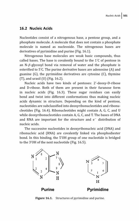
March 14, 2012 20:30 PSP Book - 9in x 6in 16-Ozsoz-c16
Nucleic Acids 501
16.2 Nucleic Acids
Nucleotides consist of a nitrogenous base, a pentose group, and a
phosphate molecule. A molecule that does not contain a phosphate
molecule is named as nucleoside. The nitrogenous bases are
derivatives of pyrimidine and purine (Fig. 16.1).
Nitrogenous base molecules are weak basic compounds, thus
called bases. The base is covalently bound to the 1′C of pentose in
an N-β-glycosyl bond via removal of water and the phosphate is
esterified to 5′C. The purine derivative bases are adenosine (A) and
guanine (G), the pyrimidine derivatives are cytosine (C), thymine
(T), and urasil (U) (Fig. 16.2).
Nucleic acids have two kinds of pentoses: 2′-deoxy-D-ribose
and D-ribose. Both of them are present in their furanose form
in nucleic acids (Fig. 16.3). These sugar residues can easily
bend and twist into different conformations thus making nucleic
acids dynamic in structure. Depending on the kind of pentose,
nucleotides are subclassified into deoxyribonucleotides and ribonu-
cleotides (Fig. 16.4). Ribonucleotides might contain A, G, C, and U
while deoxyribonucleotides contain A, G, C, and T. The bases of DNA
and RNA are important for the structure and e− distribution of
nucleic acids.
The successive nucleotides in deoxyribonucleic acid (DNA) and
ribonucleic acid (RNA) are covalently linked via phosphodiester
bond. In this binding, the 5’OH group of one nucleotide is bridged
to the 3’OH of the next nucleotide (Fig. 16.5).
Figure 16.1. Structures of pyrimidine and purine.
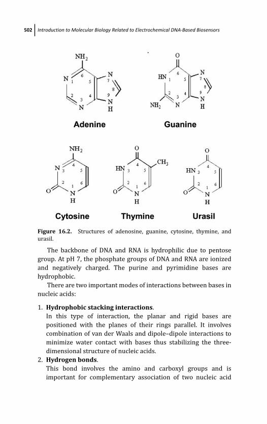
March 14, 2012 20:30 PSP Book - 9in x 6in 16-Ozsoz-c16
502 Introduction to Molecular Biology Related to Electrochemical DNA-Based Biosensors
Figure 16.2. Structures of adenosine, guanine, cytosine, thymine, and
urasil.
The backbone of DNA and RNA is hydrophilic due to pentose
group. At pH 7, the phosphate groups of DNA and RNA are ionized
and negatively charged. The purine and pyrimidine bases are
hydrophobic.
There are two important modes of interactions between bases in
nucleic acids:
1. Hydrophobic stacking interactions.
In this type of interaction, the planar and rigid bases are
positioned with the planes of their rings parallel. It involves
combination of van der Waals and dipole–dipole interactions to
minimize water contact with bases thus stabilizing the three-
dimensional structure of nucleic acids.
2. Hydrogen bonds.
This bond involves the amino and carboxyl groups and is
important for complementary association of two nucleic acid
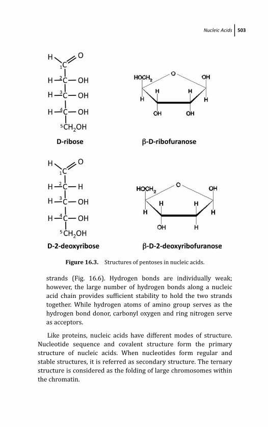
March 14, 2012 20:30 PSP Book - 9in x 6in 16-Ozsoz-c16
Nucleic Acids 503
Figure 16.3. Structures of pentoses in nucleic acids.
strands (Fig. 16.6). Hydrogen bonds are individually weak;
however, the large number of hydrogen bonds along a nucleic
acid chain provides sufficient stability to hold the two strands
together. While hydrogen atoms of amino group serves as the
hydrogen bond donor, carbonyl oxygen and ring nitrogen serve
as acceptors.
Like proteins, nucleic acids have different modes of structure.
Nucleotide sequence and covalent structure form the primary
structure of nucleic acids. When nucleotides form regular and
stable structures, it is referred as secondary structure. The ternary
structure is considered as the folding of large chromosomes within
the chromatin.
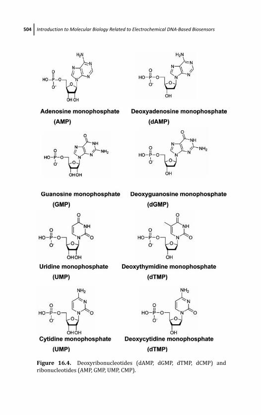
March 14, 2012 20:30 PSP Book - 9in x 6in 16-Ozsoz-c16
504 Introduction to Molecular Biology Related to Electrochemical DNA-Based Biosensors
Figure 16.4. Deoxyribonucleotides (dAMP, dGMP, dTMP, dCMP) and
ribonucleotides (AMP, GMP, UMP, CMP).
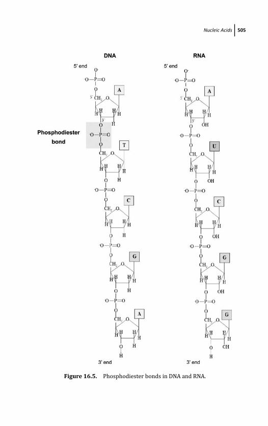
March 14, 2012 20:30 PSP Book - 9in x 6in 16-Ozsoz-c16
Nucleic Acids 505
Figure 16.5. Phosphodiester bonds in DNA and RNA.
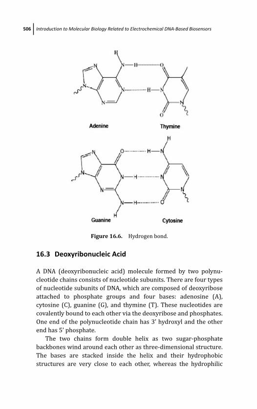
March 14, 2012 20:30 PSP Book - 9in x 6in 16-Ozsoz-c16
506 Introduction to Molecular Biology Related to Electrochemical DNA-Based Biosensors
Figure 16.6. Hydrogen bond.
16.3 Deoxyribonucleic Acid
A DNA (deoxyribonucleic acid) molecule formed by two polynu-
cleotide chains consists of nucleotide subunits. There are four types
of nucleotide subunits of DNA, which are composed of deoxyribose
attached to phosphate groups and four bases: adenosine (A),
cytosine (C), guanine (G), and thymine (T). These nucleotides are
covalently bound to each other via the deoxyribose and phosphates.
One end of the polynucleotide chain has 3’ hydroxyl and the other
end has 5’ phosphate.
The two chains form double helix as two sugar-phosphate
backbones wind around each other as three-dimensional structure.
The bases are stacked inside the helix and their hydrophobic
structures are very close to each other, whereas the hydrophilic
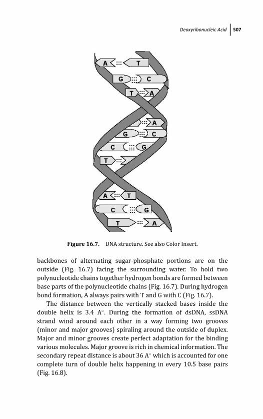
March 14, 2012 20:30 PSP Book - 9in x 6in 16-Ozsoz-c16
Deoxyribonucleic Acid 507
Figure 16.7. DNA structure. See also Color Insert.
backbones of alternating sugar-phosphate portions are on the
outside (Fig. 16.7) facing the surrounding water. To hold two
polynucleotide chains together hydrogen bonds are formed between
base parts of the polynucleotide chains (Fig. 16.7). During hydrogen
bond formation, A always pairs with T and G with C (Fig. 16.7).
The distance between the vertically stacked bases inside the
double helix is 3.4 A◦. During the formation of dsDNA, ssDNA
strand wind around each other in a way forming two grooves
(minor and major grooves) spiraling around the outside of duplex.
Major and minor grooves create perfect adaptation for the binding
various molecules. Major groove is rich in chemical information. The
secondary repeat distance is about 36 A◦ which is accounted for one
complete turn of double helix happening in every 10.5 base pairs
(Fig. 16.8).
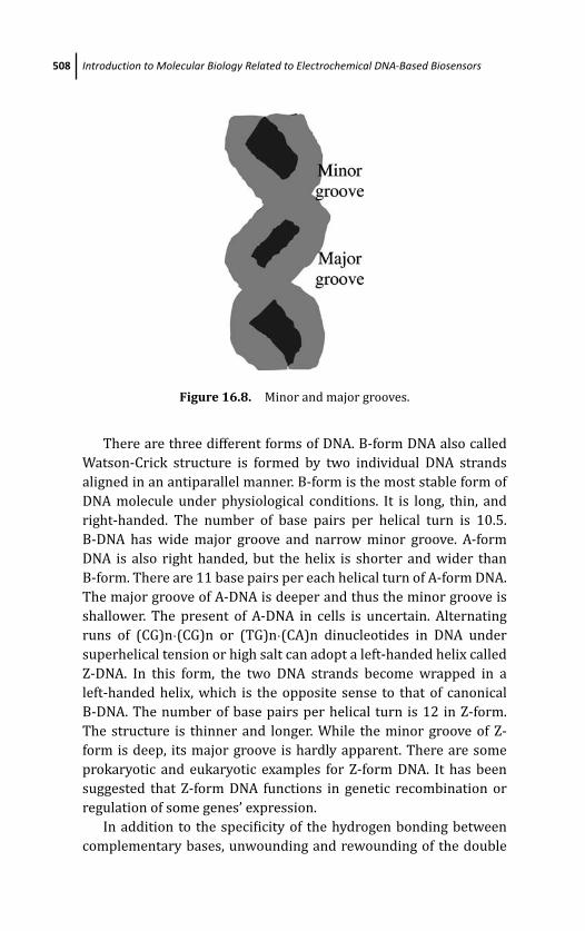
March 14, 2012 20:30 PSP Book - 9in x 6in 16-Ozsoz-c16
508 Introduction to Molecular Biology Related to Electrochemical DNA-Based Biosensors
Figure 16.8. Minor and major grooves.
There are three different forms of DNA. B-form DNA also called
Watson-Crick structure is formed by two individual DNA strands
aligned in an antiparallel manner. B-form is the most stable form of
DNA molecule under physiological conditions. It is long, thin, and
right-handed. The number of base pairs per helical turn is 10.5.
B-DNA has wide major groove and narrow minor groove. A-form
DNA is also right handed, but the helix is shorter and wider than
B-form. There are 11 base pairs per each helical turn of A-form DNA.
The major groove of A-DNA is deeper and thus the minor groove is
shallower. The present of A-DNA in cells is uncertain. Alternating
runs of (CG)n·(CG)n or (TG)n·(CA)n dinucleotides in DNA under
superhelical tension or high salt can adopt a left-handed helix called
Z-DNA. In this form, the two DNA strands become wrapped in a
left-handed helix, which is the opposite sense to that of canonical
B-DNA. The number of base pairs per helical turn is 12 in Z-form.
The structure is thinner and longer. While the minor groove of Z-
form is deep, its major groove is hardly apparent. There are some
prokaryotic and eukaryotic examples for Z-form DNA. It has been
suggested that Z-form DNA functions in genetic recombination or
regulation of some genes’ expression.
In addition to the specificity of the hydrogen bonding between
complementary bases, unwounding and rewounding of the double

March 14, 2012 20:30 PSP Book - 9in x 6in 16-Ozsoz-c16
DNA in Electrochemical DNA-Based Biosensors 509
Figure 16.9. DNA denaturation and renaturation.
helix in exactly the same configuration is one of the most important
features of DNA. Unwinding of the double helix to form two single
strands occurs by disruption of base stacking and hydrogen bonds
between paired bases. During this denaturation process, no covalent
bonds in DNA gets broken (Fig. 16.9). Heat and extreme pH features
can cause denaturation of double-stranded DNA. When temperature
or pH is returned to the physiological range unwound strands
rewind or anneal to yield intact double helix, therefore this seper-
ation of DNA strands is reversible. Each DNA molecule has a charac-
teristic denaturation temperature or melting point (Tm). Since there
are three hydrogen bonds between G and C and two hydrogen bonds
between A and T, separation of paired DNA strands is more difficult
when GC ratio is higher than AT ratio. The transition from double
helix to the single-stranded denaturated form can be detected by
monitoring the absorption of UV light at A260. Denaturation of
double-stranded nucleic acid causes an increase in absorption.
16.4 DNA in Electrochemical DNA-Based Biosensors
DNA-based biosensors are mainly based on hybridization, which
consists of DNA base pairing between two complementary nucleic

March 14, 2012 20:30 PSP Book - 9in x 6in 16-Ozsoz-c16
510 Introduction to Molecular Biology Related to Electrochemical DNA-Based Biosensors
acid strands. When mixtures of denaturated DNA from same or
different sources is slowly cooled on same medium, artificial
hybrid DNA molecules to be formed that is called hybridization.
The specificity of such biosensor systems is dependent on probe
selection and hybridization conditions. Such systems are based on
immobilization of the probe (a single-stranded DNA) to recognize its
complementary target strand in a mixture by hybridization. Target
strand is the complementary sequence of the probe. The major
aspect is the electrochemical transduction of DNA hybridization
(Grieshaber et al., 2008; Sassolas et al., 2008; Wang et al., 2008)
(Natsume et al., 2007). There are several approaches to obtain
transduction. Using redox active molecules having the ability to
bind DNA is the most commonly used approach, often referred as
labeled approach. Binding of redox active molecules might occur
via different ways such as intercalating a planar aromatic ring
between base pairs, binding in minor groove, or interaction with one
of the bases. Intercalation happens when intercalating molecules
with appropriate size and chemical properties fit in between
base pairs of DNA. These molecules are mostly planar aromatic
structures. Ethidium bromide and doxorubicin are examples of these
intercalator molecules. These intercalator molecules do not interact
significantly with single-stranded DNA (Sassolas et al., 2008).
On the other hand, changes to the electrical properties of an
interface, change in flexibility from ssDNA to the rigid dsDNA, or
the electrochemical oxidation of guanine bases are used approaches
for label-free methods for detection of DNA hybridization. There
Figure 16.10. Comparison of guanine and inosine structures.
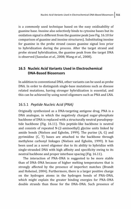
March 14, 2012 20:30 PSP Book - 9in x 6in 16-Ozsoz-c16
Nucleic Acid Variants Used in Electrochemical DNA-Based Biosensors 511
is a commonly used technique based on the easy oxidisability of
guanine base. Inosine also selectively binds to cytosine bases but its
oxidation signal is different from the guanine peak (see Fig. 16.10 for
comparison of guanine and inosine structures). Substituting inosine
for guanine in the probe strand causes guanine signal loss prior
to hybridization during the process. After the target strand and
probe strand hybridization, the guanine peak from the target DNA
is observed (Sassolas et al., 2008; Wang et al., 2008).
16.5 Nucleic Acid Variants Used in ElectrochemicalDNA-Based Biosensors
In addition to conventional DNA, other variants can be used as probe
DNA. In order to distinguish single-base mutations such as disease
related mutations, having stronger hybridization is essential, and
this can be achieved by using novel oligomers such as PNA and LNA.
16.5.1 Peptide Nucleic Acid (PNA)
Originally synthesized as a DNA-targeting antigene drug, PNA is a
DNA analogue, in which the negatively charged sugar-phosphate
backbone of DNA is replaced with a structurally neutral pseudopep-
tide backbone (Fig. 16.11). This peptide-like backbone is neutral
and consists of repeated N-(2-aminoethyl) glycine units linked by
amide bonds (Nielsen and Egholm, 1999). The purine (A, G) and
pyrimidine (C, T) bases are attached to the backbone through
methylene carbonyl linkages (Nielsen and Egholm, 1999). It has
been used as a novel oligomer due to its ability to hybridize with
single-stranded DNA with high affinity and specificity owing to its
neutral backbone and proper interbase spacing (Fig. 16.11).
The interaction of PNA–DNA is suggested to be more stable
than of DNA–DNA because of higher melting temperatures that is
strongly affected by the presence of imperfect matches (Brandt
and Hoheisel, 2004). Furthermore, there is a larger positive charge
on the hydrogen atoms in the hydrogen bonds of PNA–DNA,
which might explain the greater binding energies for PNA–DNA
double strands than those for the DNA–DNA. Such presence of
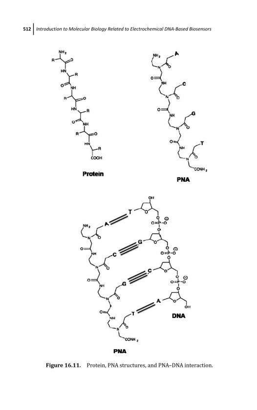
March 14, 2012 20:30 PSP Book - 9in x 6in 16-Ozsoz-c16
512 Introduction to Molecular Biology Related to Electrochemical DNA-Based Biosensors
Figure 16.11. Protein, PNA structures, and PNA–DNA interaction.
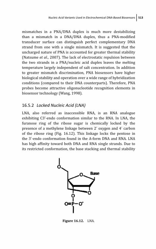
March 14, 2012 20:30 PSP Book - 9in x 6in 16-Ozsoz-c16
Nucleic Acid Variants Used in Electrochemical DNA-Based Biosensors 513
mismatches in a PNA/DNA duplex is much more destabilizing
than a mismatch in a DNA/DNA duplex, thus a PNA-modified
transducer surface can distinguish perfect complementary DNA
strand from one with a single mismatch. It is suggested that the
uncharged nature of PNA is accounted for greater thermal stability
(Natsume et al., 2007). The lack of electrostatic repulsion between
the two strands in a PNA/nucleic acid duplex leaves the melting
temperature largely independent of salt concentration. In addition
to greater mismatch discrimination, PNA biosensors have higher
biological stability and operation over a wide range of hybridization
conditions (compared to their DNA counterparts). Therefore, PNA
probes become attractive oligonucleotide recognition elements in
biosensor technology (Wang, 1998).
16.5.2 Locked Nucleic Acid (LNA)
LNA, also referred as inaccessible RNA, is an RNA analogue
exhibiting C3’-endo conformation similar to the RNA. In LNA, the
furanose ring of the ribose sugar is chemically locked by the
presence of a methylene linkage between 2′ oxygen and 4′ carbon
of the ribose ring (Fig. 16.12). This linkage locks the pentose in
the 3′-endo conformation found in the A-form DNA and RNA. LNA
has high affinity toward both DNA and RNA single strands. Due to
its restricted conformation, the base stacking and thermal stability
Figure 16.12. LNA.
March 14, 2012 20:30 PSP Book - 9in x 6in 16-Ozsoz-c16
514 Introduction to Molecular Biology Related to Electrochemical DNA-Based Biosensors
of LNA are increased. It was shown that the melting temperatures
of LNA–RNA and LNA–DNA double strands are higher than those
of DNA–RNA and DNA–DNA. Therefore, it is expected that LNA
single strand may accomplish stronger hybridization with DNA as
well as RNA. It is used to increase the specificity and sensitivity of
oligonucleotide-based DNA-biosensors (Mukhopadhyay et al., 2005;
Natsume et al., 2007).
References
O. T. Avery, C. M. McLeod, and M. McCarty, Studies on the chemical nature of
the substance-inducing transformation of pneumococcal types, J. Exp.Med. 79, 137–158 (1944).
M. J. Bessman, I. R. Lehman, E. S. Simms, and Arthur Kornberg, Enzymatic
synthesis of deoxyribonucleic acid: II. General properties of the
reaction, J. Biol. Chem. 233, 171–177 (1958).
O. Brandt and J. D. Hoheisel, Peptide nucleic acids on microarrays and other
biosensors, Trends Biotechnol. 22, 617–622 (2004).
J. P. Chambers, B. P. Arulanandam, L. L. Matta, A. Weis, and J. J. Valdes,
Biosensor recognition elements, Curr. Issues Mol. Biol. 10, 1–12 (2008).
R. Dahm, Discovering DNA: Friedrich Miescher and the early years of nucleic
acid research, Human Genetics 122, 565–581 (2008).
K. D. Fairbanks and A. S. Tavill, Liver disease in alpha 1-antitrypsin
deficiency: a review, Am. J. Gastroenterol. 103, 2136–2141, quiz 2142
(2008).
B. Gooptu, U. I. Ekeowa, and D. A. Lomas, Mechanisms of emphysema
in alpha1-antitrypsin deficiency: molecular and cellular insights, Eur.Respir. J. 34, 475–488 (2009).
D. Grieshaber, R. MacKenzie, J. Voros and E. Reimhult, Sensors, 8, 1400–1458
(2008).
S. T. Lommatzsch and R. Aris, Genetics of cystic fibrosis, Semin. Respir. Crit.Care Med. 30, 531–538 (2009).
V. A. E. McKusick, in Mendelian Inheritance in Man Johns Hopkins Univ.
Press, Baltimore, (1991).
R. Mukhopadhyay, M. Lorentzen, J. Kjems, and F. Besenbacher, Nanome-
chanical sensing of DNA sequences using piezoresistive cantilevers,
Langmuir 21, 8400–8408 (2005).
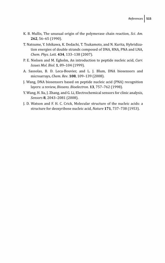
March 14, 2012 20:30 PSP Book - 9in x 6in 16-Ozsoz-c16
References 515
K. B. Mullis, The unusual origin of the polymerase chain reaction, Sci. Am.262, 56–65 (1990).
T. Natsume, Y. Ishikawa, K. Dedachi, T. Tsukamoto, and N. Kurita, Hybridiza-
tion energies of double strands composed of DNA, RNA, PNA and LNA,
Chem. Phys. Lett. 434, 133–138 (2007).
P. E. Nielsen and M. Egholm, An introduction to peptide nucleic acid, Curr.Issues Mol. Biol. 1, 89–104 (1999).
A. Sassolas, B. D. Leca-Bouvier, and L. J. Blum, DNA biosensors and
microarrays, Chem. Rev. 108, 109–139 (2008).
J. Wang, DNA biosensors based on peptide nucleic acid (PNA) recognition
layers: a review, Biosens. Bioelectron. 13, 757–762 (1998).
Y. Wang, H. Xu, J. Zhang, and G. Li, Electrochemical sensors for clinic analysis,
Sensors 8, 2043–2081 (2008).
J. D. Watson and F. H. C. Crick, Molecular structure of the nucleic acids: a
structure for deoxyribose nucleic acid, Nature 171, 737–738 (1953).

This page intentionally left blankThis page intentionally left blank

March 20, 2012 18:32 PSP Book - 9in x 6in Ozsoz-color-Insert
Color Insert
Figure 3.3
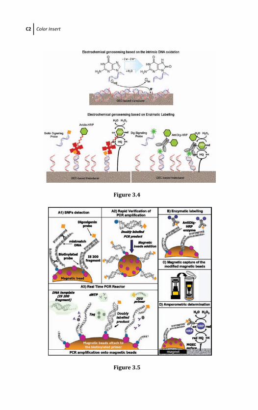
March 20, 2012 18:32 PSP Book - 9in x 6in Ozsoz-color-Insert
C2 Color Insert
Figure 3.4
Figure 3.5
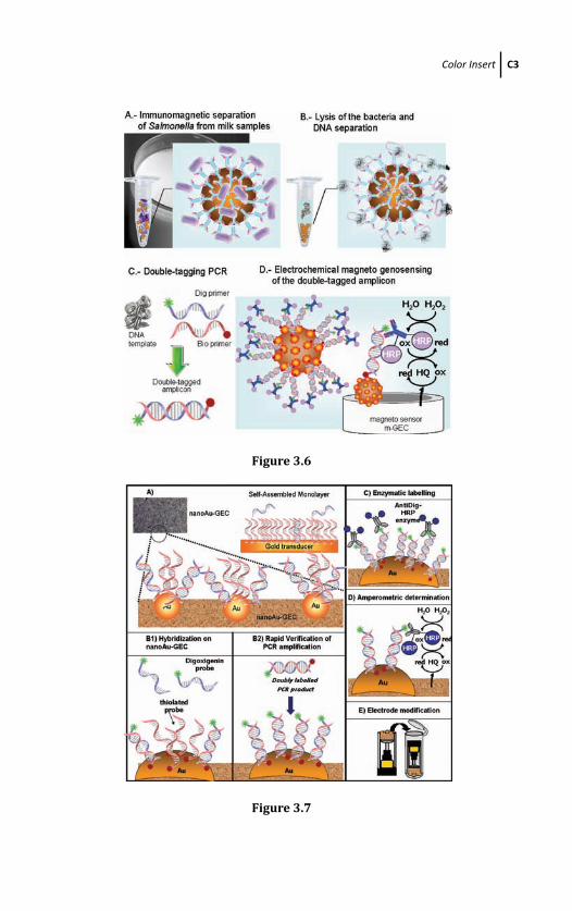
March 20, 2012 18:32 PSP Book - 9in x 6in Ozsoz-color-Insert
Color Insert C3
Figure 3.6
Figure 3.7
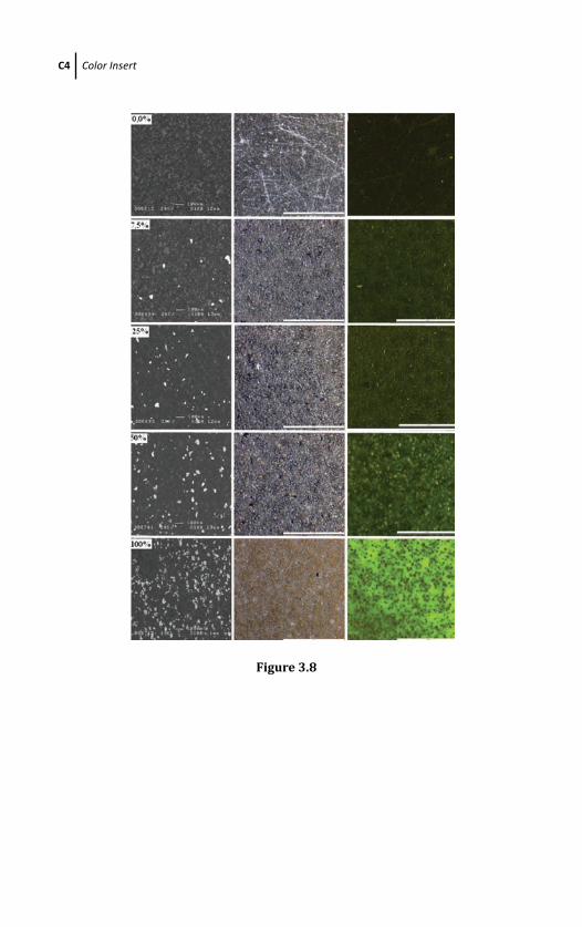
March 20, 2012 18:32 PSP Book - 9in x 6in Ozsoz-color-Insert
C4 Color Insert
Figure 3.8
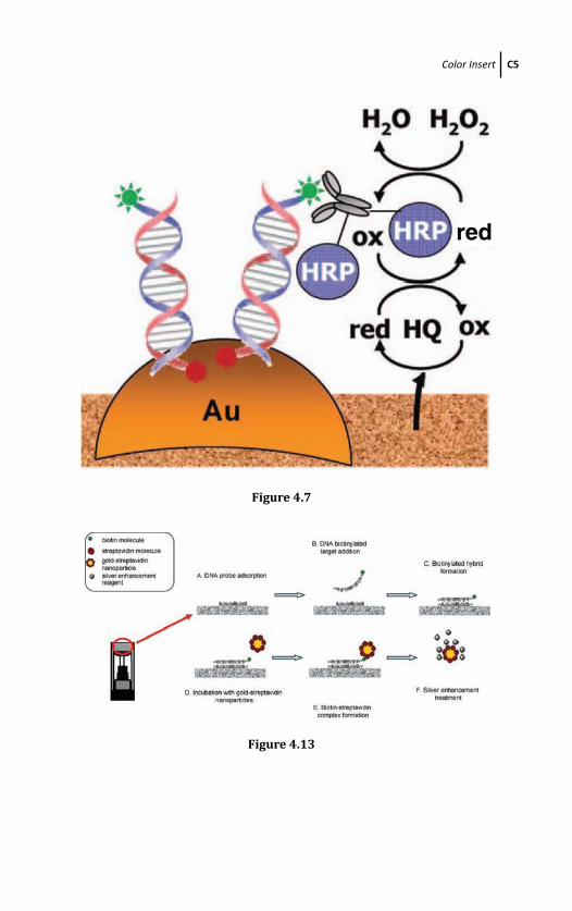
March 20, 2012 18:32 PSP Book - 9in x 6in Ozsoz-color-Insert
Color Insert C5
red
Figure 4.7
Figure 4.13
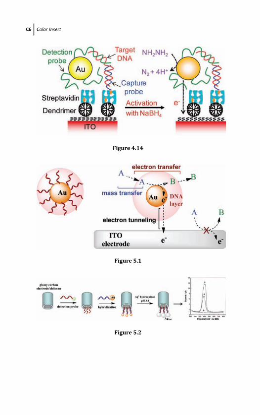
March 20, 2012 18:32 PSP Book - 9in x 6in Ozsoz-color-Insert
C6 Color Insert
Figure 4.14
Figure 5.1
Figure 5.2
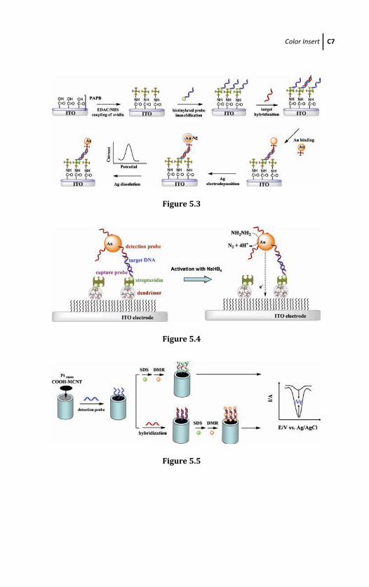
March 20, 2012 18:32 PSP Book - 9in x 6in Ozsoz-color-Insert
Color Insert C7
Figure 5.3
Figure 5.4
Figure 5.5
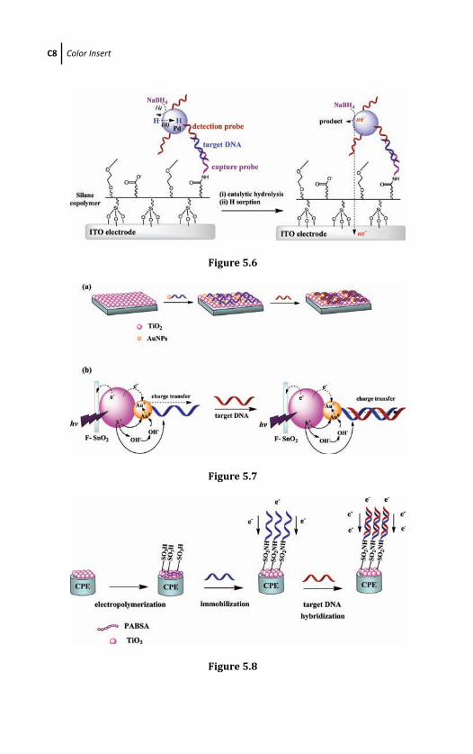
March 20, 2012 18:32 PSP Book - 9in x 6in Ozsoz-color-Insert
C8 Color Insert
Figure 5.6
Figure 5.7
Figure 5.8
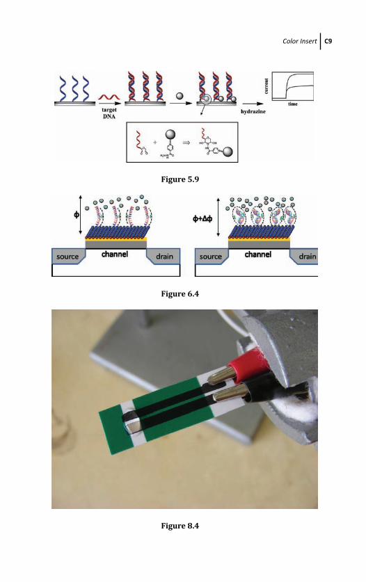
March 20, 2012 18:32 PSP Book - 9in x 6in Ozsoz-color-Insert
Color Insert C9
Figure 5.9
Figure 6.4
Figure 8.4

March 20, 2012 18:32 PSP Book - 9in x 6in Ozsoz-color-Insert
C10 Color Insert
Figure 8.9
Figure 8.10
Figure 8.15
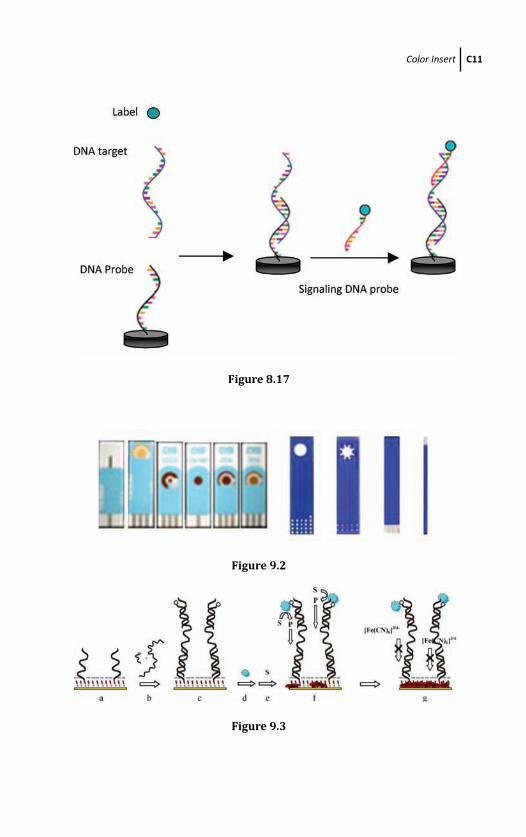
March 20, 2012 18:32 PSP Book - 9in x 6in Ozsoz-color-Insert
Color Insert C11
Figure 8.17
Figure 9.2
Figure 9.3
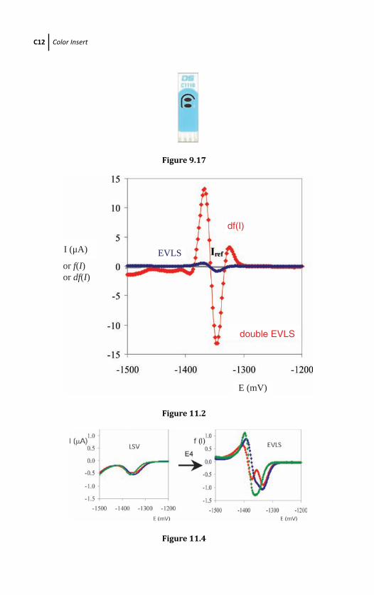
March 20, 2012 18:32 PSP Book - 9in x 6in Ozsoz-color-Insert
C12 Color Insert
Figure 9.17
double EVLS
I (μA) EVLS
df(I)
E (mV)
or f(I)or df(I)
Figure 11.2
Figure 11.4
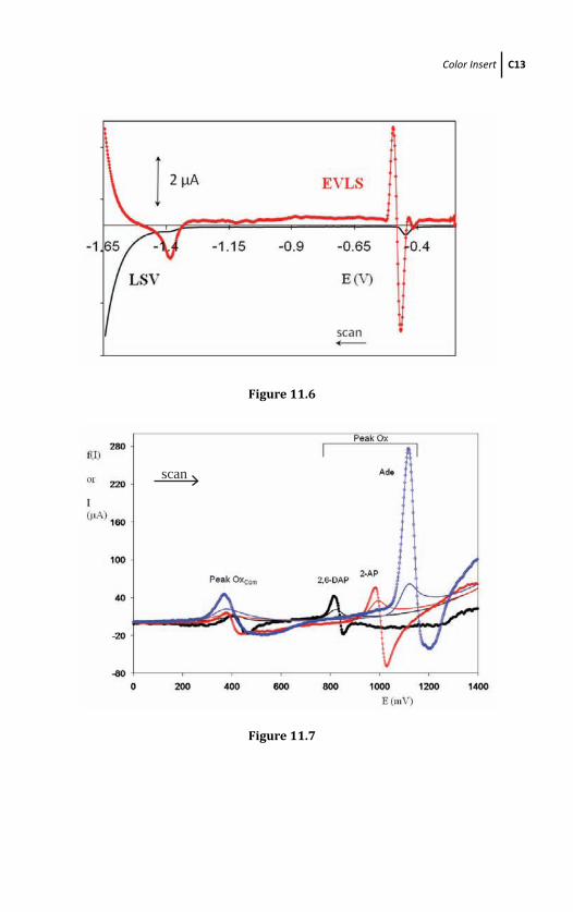
March 20, 2012 18:32 PSP Book - 9in x 6in Ozsoz-color-Insert
Color Insert C13
Figure 11.6
scan
Figure 11.7
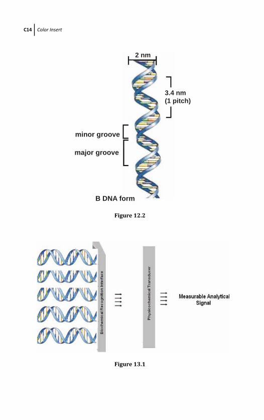
March 20, 2012 18:32 PSP Book - 9in x 6in Ozsoz-color-Insert
C14 Color Insert
2 nm
minor groove
major groove
B DNA form
3.4 nm(1 pitch)
Figure 12.2
Figure 13.1
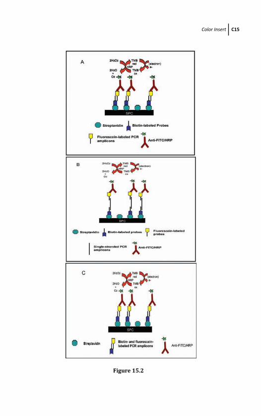
March 20, 2012 18:32 PSP Book - 9in x 6in Ozsoz-color-Insert
Color Insert C15
Figure 15.2
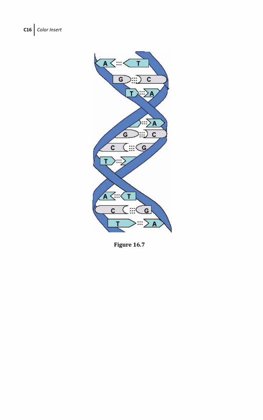
March 20, 2012 18:32 PSP Book - 9in x 6in Ozsoz-color-Insert
C16 Color Insert
Figure 16.7

ELECTROCH
EMICA
L DN
A BIOSEN
SORS
ELECTROCHEMICAL DNA
B I O S E N S O R S
Edited by
Mehmet Ozsoz
Ozsoz
Mehmet Sengun Ozsoz is a professor of analytical chemistry in the Faculty of Pharmacy at Ege University and also teaches biosensor technology courses in the Biotechnology Department at Izmir Institute of Technology. Prof. Ozsoz holds a BS in chemical engineering from Middle East Technical University, Ankara, Turkey, and a PhD in analytical chemistry from the Faculty of Pharmacy, Ege University, Izmir, Turkey. He was a postdoctoral fellow with Dr Joseph Wang at New Mexico State University, Las Cruces, between 1989–1991 and 1996–1997. He is a recipient of
the 2008 Scientific and Technological Research Council of Turkey (TUBITAK) science award. Prof. Ozsoz conducts well-recognized international work on electrochemical DNA biosensors.
“The marriage of natural and synthetic nanotechnology in electrochemical DNA sensors is
a fascinating object of research. The reader gets an easy access to the complex matter by
the well-written introductory chapter. This volume builds a bridge from molecular biology
to the applications in medical diagnostics and microbiology.”
Prof. Frieder SchellerUniversität Potsdam, Germany
“This book is a very welcome contribution to the literature of electrochemical DNA
biosensors. It offers extremely useful insights into this exciting and important field.”
Dr. Joseph WangUniversity of California, San Diego, USA
This book focuses on the electrochemical applications of DNA in various areas, from basic
principles to the most recent discoveries. It comprises theoretical and experimental analyses
of various properties of nucleic acids, research methods, and some promising applications.
The topics discussed in the book include electrochemical detection of DNA
hybridization based on latex/gold nanoparticles and nanotubes; nanomaterial-
based electrochemical DNA detection; electrochemical detection of microorganism-
based DNA biosensor; gold nanoparticle-based electrochemical DNA biosensors;
electrochemical detection of the aptamer–target interaction; nanoparticle-induced
catalysis for DNA biosensing; basic terms regarding electrochemical DNA (nucleic
acids) biosensors; screen-printed electrodes for electrochemical DNA detection;
application of field-effect transistors to label-free electrical DNA biosensor arrays;
and electrochemical detection of nucleic acids using branched DNA amplifiers.