electricity - physicsforum.ins law 1.pdf · in an experiment to study the dependence of current on...
TRANSCRIPT

ELECTRICITY PROBLEMS BASED ON
PRACTICAL SKILLS

To determine the equivalent resistance of two resistors when
connected in series, a student arranged the circuit
components as shown in the diagram. But he did not succeed
to achieve the objective. Which of the following mistakes has
been committed by him in setting up the circuit?
(A) Position of ammeter is incorrect.
(B) Position of voltmeter is incorrect.
(C) Terminals of ammeter are wrongly connected.
(D) Terminals of voltmeter are wrongly connected.
1

The following circuit diagram shows the experimental set-up
for the study of dependence of current on potential difference.
Which two circuit components are connected in series?
(A) Battery and voltmeter (B) Ammeter and voltmeter
(C) Ammeter and Rheostat (D) Resistor and Voltmeter
2

For the circuit arrangement shown below, a student would
observe:
(A) Some reading in both the ammeter and the voltmeter.
(B) No reading in either the ammeter or the voltmeter.
(C) Some reading in the ammeter but no reading in the voltmeter.
(D) Some reading in the voltmeter but no reading in the ammeter.
3

In an experiment to determine equivalent resistance of two
resistors R1 and R2 in series, which of the circuit correctly
shows connection the voltmeter in the circuit?
(A) (i) only
(B) (i) and (iii)
(C) (iii) only
(D) (ii) and (iv)
4

Which two circuit components are connected in parallel in
the following circuit diagram?
(A) Rheostat and voltmeter (B) Voltmeter and resistor
(C) Voltmeter and Ammeter (D) Ammeter and resistor
5

In an experiment to study the dependence of current on
potential difference across a resistor, a student obtained the
graph as shown in the diagram. The value of resistance of the
resistor is,
(A) 0.1 ohm (B) 1.0 ohm
(C) 10 ohm (D) 100 ohm.
6
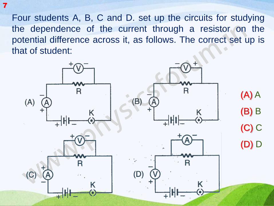
Four students A, B, C and D. set up the circuits for studying
the dependence of the current through a resistor on the
potential difference across it, as follows. The correct set up is
that of student:
(A) A
(B) B
(C) C
(D) D
7

The given circuit diagram shows the experimental
arrangement of difference circuit components for
determination of equivalent resistance of two resistors
connected in series. The components X, Y and Z shows in the
circuit respectively represent.
(A) Rheostat, Resistor, Ammeter
(B) Ammeter, Voltmeter, Rheostat
(C) Voltmeter, Ammeter, Rheostat
(D) Rheostat, Ammeter, Voltmeter
8

The current flowing through a resistor and the potential
difference developed across its ends are show in the given
diagrams.
The values of resistance of the resistor is
(A) 0.529 ohm (B) 5.29 ohm
(C) 529 ohm (D) 500 ohm
9

In the experiment on finding the equivalent resistance of two
resistors, connected in parallel, three students connected the
voltmeter in their circuits, in the three ways, X,Y and Z shown
here.
The voltmeter has been correctly connected in:
(A) cases X and Y only (B) cases Y and Z only
(C) cases Z and X only (D) all the three cases
10

Students A and B connect the two resistors R1 and R2 given to
them in the manners shown below:
And then insert them at X and Y into the measuring circuit
shown below:
We can say that
11

(A) both the students will determine the equivalent resistance
of the series combination of R1 and R2.
(B) both the students will determine the equivalent resistance
of the parallel combination of R1 and R2.
(C) Student A will determine the equivalent resistance of the
series combination while student B will determine the
equivalent resistance of the parallel combination of R1 and
R2
(D) Student A will determine the equivalent resistance of the
parallel combination while student B will determine the
equivalent resistance of the series combination of R1 and
R2.

To study the dependence of current (I) on potential difference
(V) across a resistor R, two students used the two set ups
shown in figure A and B respectively. They kept the contact
point J in four different positions, marked (i), (ii), (iii) and (iv)
in the two figures.
For the two students, the ammeter and voltmeter readings will be
maximum when the contact J is in the position:
(A) (iv) in both the set ups (B) (i) in both the set ups
(C) (iv) in set up A and (i) in set up B (D) (i) in set up A and (iv)
in set up B
12

In the experiment on finding the equivalent resistance of two
resistors connected in series, three students connected the
ammeter in their circuits in the three ways X, Y and Z as shown
here. Assuming their ammeters to be ideal, the ammeter have been
correctly connected in
(A) cases X and Y only (B) cases Y and Z only
(C) cases Z and X only (D) all the three cases
13

Which of the circuit components in the following circuit
diagram are connected in parallel?
(A) R1 and R2 only (B) R1, R2 and V
(C) R2 and V only (D) R1 and V only
14

To determine the equivalent resistance of a series combination of
two resistors R1 and R2, a student arranges the following set up.
Which one of the following statements will be true for this circuit?
It gives:
(A) incorrect reading for current I as well as potential difference V.
(B) correct reading for current I but incorrect reading for potential difference V.
(C) correct reading for potential difference V but incorrect reading for current I.
(D) correct reading for both I and V.
15

The correct set up for determining the equivalent resistance if two
resistors R1 and R2 when connected in parallel is
(A) (I)
(B) (II)
(C) (III)
(D) (IV)
16
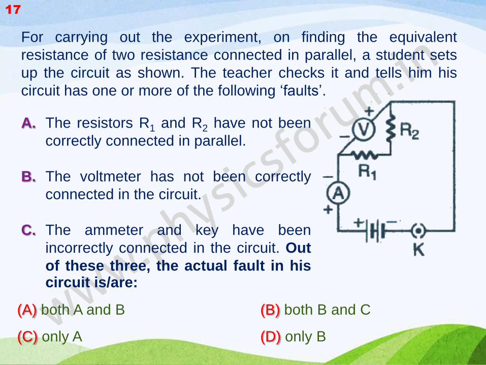
For carrying out the experiment, on finding the equivalent
resistance of two resistance connected in parallel, a student sets
up the circuit as shown. The teacher checks it and tells him his
circuit has one or more of the following ‘faults’.
(A) both A and B (B) both B and C
(C) only A (D) only B
17
A. The resistors R1 and R2 have not been
correctly connected in parallel.
B. The voltmeter has not been correctly
connected in the circuit.
C. The ammeter and key have been
incorrectly connected in the circuit. Out
of these three, the actual fault in his circuit is/are:

While doing experiment, on finding the equivalent resistance of two
resistors connected in series, three students A, B and C set up their
circuit as shown below:
The correct set up is that of:
(A) students A and B (B) students B and C
(C) students C and A (D) all the three students
18

For the circuits shown in Figure I and II, the voltmeter reading would
be:
(A) 2V in circuit (I) and 0V in circuit (II)
(B) 0V in both circuits
(C) 2V in both circuits
(D) 0V in circuit (I) and 2V in circuit (II)
19

In a voltmeter, there are 20 divisions between the 0 mark and
0.5 V mark. The least count of the voltmeter is:
(A) 0.020 V
(B) 0.025 V
(C) 0.050V
(D) 0.250V
20

The current flowing through a conductor and the potential
difference across its two ends are as per readings of the
ammeter and the voltmeter shown below. The resistance of
the conductor would be:
(A) 0.02 ohm (B) 0.24 ohm
(C) 20.4 ohm (D) 24.0 ohm
21

The following instruments are available in laboratory:
Milliammeter A1 of range 0 - 300 mA and least count 10 mA.
Milliammeter A2 of range 0 - 200 mA and least count 50 mA.
Voltmeter V1 of range 0 - 5V and least count 0.2V.
Voltmeter V2 of range 0-3V and least count 0.3V.
(A) Milliammeter A1 and voltmeter V1
(B) Milliammeter A2 and voltmeter V2
(C) Milliammeter A1 and voltmeter V2
(D) Milliammeter A2 and voltmeter V1
22
Out of the following pairs of instruments, which pair would be
the best choice for carrying out the experiment to determine the
equivalent resistance of two resistors connected in series?

Which one of the given four milliammeter would you use for
measurement of current flowing in a circuit?
(A) I
(B) II
(C) III
(D) IV
23

The resistors R1 and R2 are connected in:
(A) parallel in both circuits.
(B) series in both circuits.
(C) parallel in circuit I and in series in circuit II.
(D) series in circuit I and in parallel in circuit II.
24

Circuit I : ammeter reads current i1 and voltmeter reads V1
Circuit II : ammeter reads current i2 and voltmeter reads V2
The relationship between the readings is
(A) i1 > i2; V1 = V2 (B) i1 < i2; V1 = V2
(C) i1 > i2; V1 > V2 (D) i1 < i2; V1 < V2
25

ANSWER KEY
1 2 3 4 5 6 7 8 9 10
C C A B B C A B B D
11 12 13 14 15 16 17 18 19 20
C C A B B B A B D B
21 22 23 24 25
C A B C B