electricity: get charged!...electricity is a result of the distribution of positively and negatively...
TRANSCRIPT


www.scientistsinschool.ca 1
Electricity: Get Charged!
Flash! Crack goes the thunder!! The lights flicker and then the house is silent. The fridge, computer, cordless phone and all other electrical devices in the house cease to function when the power goes out. Most Canadians depend on the electricity grid and when the power goes out, we can get into a bit of a panic. There are many alternatives that we quickly learn will help us to cope during a power disruption. Candles and a battery powered flashlight can be used along with a human-powered crank radio. A wood burning stove or natural gas fireplace can be used to heat the house. Power outages demonstrate how essential electricity has become for modern life. Benjamin Franklin conducted his famous kite experiment to illustrate the electrical nature of lightning in 1752. In 1800, Alessandro Volta made the first battery. In 1819-1820, Hans Christian Orsted and Andre-Marie Ampere identified the link between electricity and magnetism, which led to Michael Faraday’s invention of the electric motor. Using the electrical synapses in their brains, people in modern times have found ways of converting the energy from fossil fuels, water, uranium, sun, hydrogen, biomass and wind into electricity.
Background Information Matter is made of atoms. Each atom contains a nucleus surrounded by one or more negatively charged electrons. The nucleus consists of positively charged protons and neutral neutrons. Atoms are electrically neutral if they have an equal number of electrons and protons. An atom is electrically charged if it contains an unequal number of protons and electrons. An electrically charged atom is called an ion. The movement of electrons can produce static or current electricity. Static Electricity
Static electricity occurs when electric charges accumulate on an insulated body, often as a result of friction. For example, when a rubber balloon is rubbed on hair, the electrons move from the hair to the balloon resulting in an overall positive charge in the hair and an overall negative charge on the balloon. Sudden discharge of this differential charge can result in sparks, as sometimes happens when taking socks out of the dryer, or on a much larger scale, when you see lightning. Current Electricity
Current electricity occurs when electric charge flows. The rate of flow of electric current is measured in amperes (amps) by a device called an ammeter. The current from a battery or solar cell is considered direct current (DC) since it flows in one direction. Electrons flow from the negative terminal, where there is an excess of electrons, to the positive terminal, where there is a deficit of electrons. Alternating current (AC) is the form of electricity delivered to residences and businesses in which the electric current reverses direction at regular intervals. This enables power companies to inexpensively transmit high voltages over long distances and then convert to lower voltages for distribution. Voltage (electric potential difference)
Voltage is the difference in electric potential energy between two points. Voltage is measured in volts (V) using a voltmeter connected between two points. A volt measures the force or “push” of an electric current. A galvanic cell is the source of voltage in some electrical circuits. To make a cell, two different metal plates are placed into an electrolyte, which is a solution of ions. The metals react so that electrons move from one metal plate, which becomes the positive terminal or cathode, and collect on the negative terminal or anode. A battery is technically composed of many cells. The term “battery” is commonly used to refer to either a cell or a battery. For example, AA battery is one cell whereas a 9V battery has three cells. Both AAA and D size batteries provide 1.5 V each but the bigger battery can provide more current.

www.scientistsinschool.ca 2
Conductors and Insulators
Resistance is a measure of the hindrance of the flow of charge and is measured in ohms (Ω). Some materials allow charge to move more easily through them than others. Conductors are materials which are made of atoms that have loosely bound electrons which can move freely and easily. Examples of conductors are metals such as copper and aluminium. When certain ionic compounds are dissolved in water, the resulting salt solution can also conduct electricity. The conductivity of materials is a continuum with good conductors on one end and poor conductors on the other. However, some materials are so poor in allowing the movement of charge, they are considered insulators. Insulators are materials which prevent the free flow of electrons. When two materials that are good insulators, such as rubber, glass and wood, are rubbed together the static electric charge builds up and the electrons can then move between the materials. Series and Parallel Circuits
A circuit consists of an electrical path through which a current returns to its source. Generally, the path consists of a power source, like a battery; a load, such as a light bulb; connecting conducting wires; and a control device, such as a switch. A switch can be closed to complete the circuit or open to interrupt the circuit. A series circuit is connected so there is one single path for the current to follow. This means that if any one component in a series circuit is no longer conducting electricity, the entire circuit will fail to function. An example of this may occur on an inexpensive string of lights: when one bulb goes out, the entire string does not function. In contrast, in a parallel circuit, the current divides into more than one branch before recombining to complete the circuit. Thus, one part of the circuit can still function if another path is interrupted. The wiring in homes uses parallel circuits allowing different appliances to switch on and off while using the same circuit.
Electricity and Magnetic Fields
A magnetic field is created when an electric current flows through a wire. The magnetic field forms concentric circles around the wire, in a direction that is perpendicular to the wire. An electromagnet is a piece of coiled wire surrounding a magnetic core, usually a piece of metal. The wire has electric current flowing through it and the magnet can be turned on and off. It is designed to maximize the strength of the magnetic field for a specific purpose, such as picking up cars at a wrecking yard. Electricity is a result of the distribution of positively and negatively charged particles. In a power plant, a turbine and generator work by transforming the mechanical energy of moving steam into electrical energy. The end of the turbine shaft is connected to a generator containing a magnet and a coil of wire. The rotation of the magnet relative to the coil of wire induces an electric current in the wire. The electric current moves through huge transmission wires that link the power plant to our homes and businesses.
Series Circuit Parallel Circuit
(Source: http://www1.curriculum.edu.au/sciencepd/electricity/images/elec_ill76.gif)

www.scientistsinschool.ca 3
Activity 1: Energy Conservation: Lights Out!
3. Time: 7 hours at home; 40 minutes at school Other Applications: math Key-terms: watts, power, energy, incandescent, compact fluorescent light (CFL), light emitting diodes (LED), extrapolate, mean, medium, mode, range Group Size: individual data collection and analysis, class data analysis Materials:
□ “Energy Conservation: Personal Light Use Study” datasheet
□ pencil
□ calculator
Learning Goal: The students will learn about light usage and energy consumption. Traditional incandescent light bulbs are not very energy efficient as less than ten percent of the electrical power supplied to the bulb is converted into visible light, with the remaining energy lost as heat. Incandescent bulbs produce light by heating a tungsten filament with an electric current. The electricity cost for these bulbs is 5 to 10 times more than the cost of the bulb itself. In a move to cut energy consumption, Canada introduced a federal ban in 2014 on the manufacturing and importing of traditional incandescent light bulbs. Alternatives for more energy efficient options include halogen incandescent, fluorescent, compact fluorescent (CFL) and light emitting diode (LED) bulbs. Halogen incandescent bulbs use halogen gas and are slightly more energy efficient than a traditional incandescent bulb. Fluorescent bulbs produce light differently in that the gas within the bulb is charged as an electric current passes through. CFLs are designed to be much more energy efficient. LEDs are longer-lasting than CFLs, cool and durable. The disadvantage of LEDs is that they are costly to produce and the beam is very focused and narrow. Technological advances continue to improve the cost and effectiveness of LEDs to the point that they will likely replace CFLs and all incandescent lighting. The following websites provide comparisons and descriptions of the different types of lighting:
http://www.designrecycleinc.com/led%20comp%20chart.html (11/03/16) http://eartheasy.com/live_energyeff_lighting.htm (11/03/16)
Procedure: 1. Provide an overview of the activity: students will be collecting
data about their personal light usage during a seven hour time period at home. This data will be used to calculate light energy usage in seven hours and then extrapolated to approximate a 24 hour period. The individual data between students will be compiled to form a class dataset and then analyzed and extrapolated for the year.
2. Hand out the “Energy Conservation: Personal Light Use Study” datasheet to each student. Instruct the students that they will be tracking their light energy usage over a total of any seven hours in which they are at home. The students do not have to record the seven hours consecutively, if they are not at home for that many hours in a row.
Fun Fact: Earth Hour Every Day? Did you know that in
2013, Toronto Hydro, the largest municipal
electricity distribution company in Canada,
recorded a 7 % drop from the regular load
during Earth Hour…this is equal to taking
92 000 homes off the power grid!

www.scientistsinschool.ca 4
At home, each student will record the following information for each light that is on in the room they are spending time in:
● Column 1: room spending time in and light description if there is more than one light in the room (e.g. bedroom, desk lamp)
● Column 2: amount of time spent in the room in minutes
● Column 3: type of bulb in the fixture – review differences between types of bulbs (halogen incandescent, compact fluorescent light (CFL), and light emitting diodes (LED))
● Column 4: number of bulbs (N) within each fixture
● Column 5: power wattage (P(W)) for each bulb. It is important to stress safety and enlist the help of adults when determining the power for each bulb. SAFETY: If the adult or student does not know the wattage for a particular bulb and needs to read the watts written on the bulb, the light should be off and/or unplugged and allowed to cool completely before reading the information written on the light bulb.
4. At school, each student will calculate values for column 6 & 7:
● Column 6 - the amount of time the light was on, or elapsed time (t(h)), is converted from minutes to hours by dividing the number of minutes (column 2) by 60.
● Column 7 – Energy Usage (E(Wh)) used by that light fixture: = Number of light bulbs x Power Wattage x Elapsed Time (N, column 4) (P(W), column 5) (t(h), column 6)
5. Instruct students to calculate the values at the bottom of their datasheets:
● Value 8 – the total amount of energy (watt-hour) that they used within the seven hour time period is calculated by adding up the total for column 7.
● Value 9 – an estimate of the total amount of light energy usage (watt-hour) in a 24 hour time period. This estimate is calculated by assuming the students are awake for 14 hours and sleeping for 10 hours with no lights on. The 14 hour value is calculated by doubling the amount of light energy used in a seven hour period (Value 8).
● Value 10 – total energy usage (kilowatt-hour) is calculated by dividing Value 9 by 1000.
6. Have a class discussion about their individual results. Ask students which light bulbs are most efficient and which are least efficient. A class discussion about energy usage and conservation can then ensue. Encourage students to compare and discuss any differences they notice and how it may affect the amount of energy that they use.

www.scientistsinschool.ca 5
Observations: A sample completed “Energy Conservation: Personal Light Use Study” datasheet has been provided below with appropriate calculations.
1 2 3 4 5 6 7
Type of Room
Time spent in
room (min)
Type of bulb
# bulbs (N)
Power (P(w), Watt)
Elapsed time (t(h), hour)
Energy usage (E(wh), Watt-hour)
E(wh) = N x P(w) x t(h)
bedroom, night table
60 min (6-7 am)
CFL 1 11 W 1 h 11 Wh
{1 x 11 W x 1 h}
upstairs bathroom
30 min (6-6:30 am)
Incand. 6 40 W 30min / 60 = 0.5 h 120 Wh
{6 x 40 W x 0.5 h}
bedroom, dresser light
15 min (6:30-6:45
am)
CFL 1 11 W 15min / 60 = 0.25 h 2.75 Wh
{1 x 11 W x 0.25 h}
front hall 60 min
(6:45-7:45 am)
CFL 1 11 W 1 h 11 Wh
{1 x 11 W x 1 h}
kitchen, over counter
60 min (6:45-7:45
am)
CFL 5 13 W 1 h 65 Wh
{5 x 13 W x 1 h}
kitchen, over table
60 min (6:45-7:45
am)
CFL 2 15 W 1 h 30 Wh
{2 x 15 W x 1 h}
basement, near TV
180 min (8-11 am)
Incand. (halogen)
4 50 W 3 h 600 Wh
{4 x 50 W x 3 h} basement, overhead
180 min (8-11 am)
LED 6 7 W 3 h 126 Wh
{6 x 7 W x 3 h} kitchen, over
counter 120 min (4-6 pm)
CFL 5 13 W 2 h 130 Wh
{5 x 13 w x 2 h} kitchen, over
table 120 min (4-6 pm)
CFL 2 15 W 2 h 60 Wh
{2 x 15 w x 2 h}
Value 8: Total Energy Usage (Wh) over 7 hour time period 1155.75 Wh Value 9: Estimate of total energy usage in 24 hour = Value 8 x 2 (assuming lights are off during 10 hours of sleep)
2311.5 Wh
Value 10: Total Energy Usage in kilowatt-hour = Value 9 / 1000 2.31 kWh
Discussion: The amount of energy that a fixture uses depends on the time that the light is left on, the type and the number of light bulbs within that fixture. The type of bulb has probably the greatest impact on energy usage. Incandescent light bulbs use far more power than CFLs or LEDs. Also, the more light bulbs in the fixture, the greater the amount of energy used by that fixture. Students have some control over turning lights on or off in their homes. They can become ambassadors for energy conservation at home by turning lights off when leaving the room and suggesting more efficient light bulbs and lights.

www.scientistsinschool.ca 6
Extensions: 1. Have students extend their analysis to examine light usage for the entire class. Compile all of the
students “value 10” on the board or on chart paper such that the values are anonymous. Have students record each classmate’s daily total light energy usage values (kilowatt-hour). Have students calculate the class mean, median, range and mode. Have students extrapolate the class annual light energy usage (kWh/year) by multiplying the class mean/day x 365 days/year.
2. Other than the amount of energy, determine other advantages or disadvantages of using incandescent light bulbs, CFLs or LEDs. These can include environmental concerns, amount of light (lumens) and the type of light emitted (i.e. warm or cold, based on wavelengths), cost and life expectancy. Record this information in a Venn diagram or chart.
3. Research online to determine the amount of energy saved during Earth Hour in a major city in Canada when everyone turns out their lights. Explain how Earth Hour began and describe its importance other than simply saving electricity during the hour. The following website provides current and past details about Earth Hour: http://www.earthhour.org/ (11/03/16).
4. Students can repeat the activity with the goal of conserving as much energy as possible. They can then calculate their energy usage again for this energy conservation day. The teacher can calculate a class average. Individual students can then calculate their personal percent reduction and the average class reduction. Similarly, the activity can be repeated at a different time of year (e.g. winter versus spring or fall) and compare how daylight hours affect our light energy usage.
5. Have a class discussion about the electrical devices we use daily. Which use the most and least energy? Students can determine which devices they could use less or eliminate completely. For example, allowing hair to air dry, instead of using a blow dryer.
6. Exploring our home energy usage: ● Part 1: Electric utilities use the kilowatt-hour as a billing unit for energy. Students could
determine the current rate for their house and calculate how much it costs to keep their lights on for a year.
● Part 2: Have students calculate the gigajoules of energy required to turn their lights on for a day and a year by multiplying the kWh by 0.0036. In science, energy is measured in Joules. One Joule is a relatively small amount of energy. For example, it takes 4,184 Joules of energy to raise the temperature of 1 litre of water by 1 degree Celsius. Since 1 Joule is a small number, energy consumption is often discussed in terms of gigajoules (GJ) which is equivalent to 1,000,000,000 J.
1 watt = 1 J/s, therefore 1 kW = 1 kJ/s; there are 3600 seconds in one hour, therefore 1 kW per hour = 1 kJ/s x 3600 seconds
= 3600 kJ = 3.6 MJ (megajoule) = 0.0036 GJ.
Fun Fact: Speedy Electricity! Electricity travels at the speed of light - more than
300 000 kilometers per second! If you had a switch in your house connected to a lamp on the moon, it would take only 1.28 seconds for the lamp to light up after
you turned it on 384 403 kilometers away.
www.scientistsinschool.ca 7
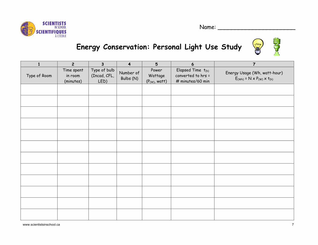
Name: ______________________
Energy Conservation: Personal Light Use Study
1 2 3 4 5 6 7
Type of Room Time spent
in room (minutes)
Type of bulb(Incad, CFL,
LED)
Number of Bulbs (N)
Power Wattage
(P(W), watt)
Elapsed Time t(h)
converted to hrs = # minutes/60 min
Energy Usage (Wh, watt-hour) E(Wh) = N x P(W) x t(h)

www.scientistsinschool.ca 8
1 2 3 4 5 6 7
Description (room, light)
Time Spent in Room
(minutes)
Type of Bulb(Incand., CFL, LED)
Number of Bulbs (N)
Power Wattage
(P(W), watt)
Elapsed Time t(h)
converted to hrs = # minutes/60 min
Energy Usage (Wh, watt-hour) E(Wh) = t(h) x N x P(W)
Value 8, Total Energy Usage (Wh, watt-hour) in a 7 hour time period
Value 9, estimate of total energy usage (Wh, watt-hour) in a 24 hour time period = Value 8 x 2 (assumption: awake for 14 hours and sleeping for 10 hours with no lights on)
Value 10, the total energy usage converted to kilowatt-hour (kWh) = Value 9 / 1000

www.scientistsinschool.ca 9
Activity 2: Static Boat Race
Time: 30-45 minutes Other Applications: problem solving, measurement Key terms: static electricity, charge, attraction, repulsion Group Size: 2-3 students Materials (per group):
□ plastic mushroom tray
□ plasticine
□ bamboo skewer
□ straw
□ scissors, ruler
□ Styrofoam ball (4 cm)
□ variety of rods (e.g. round plastic pen, plastic ruler, wood dowel/ruler, glass stirring rod, metal rod, ebonite if available)
□ variety of materials (e.g. hair/fur, wool, cotton, silk, rubber, balloons, acetate overhead sheet)
□ container for water (e.g. wallpaper trough, sink, bucket, plastic bin)
□ stopwatch or timer
□ “Static Boat Race” datasheet
Learning Goal: The students will learn about which materials produce the most static electricity. All matter is made up of atoms. Atoms are made up of neutrons (no charge), protons (positive charge) and electrons (negative charge). When an atom has the same number of protons and electrons, it is neutral. Static electricity occurs when two materials are rubbed together and electrons move from one atom to another thereby changing the charge of the atoms. If two things have the same charge then they repel each other. If two things have opposite charges then they attract each other. It is easier to generate static electricity in a dry versus humid environment. Thus static electricity activities will be more successful during the dry winter months. Procedure: 1. Provide the students with an overview of static electricity and
how it is produced. They will be working in small groups to build a boat and using the power of static electricity to make it move. Students will be testing different materials, or combination of materials, to determine what will make their boat move the fastest.
2. Provide each group with materials to build a boat. Instruct the students to put a small amount of plasticine in the centre of the mushroom container.
● The “mast” of the boat is made using the straw and bamboo skewer. Trim the straw so that it measures 8 cm and place the straw vertically into the plasticine. Trim the bamboo skewer so it measures 10 cm and place it inside the straw into the plasticine so that the pointed end is up.
● The “sail” of the boat is made with the Styrofoam ball by placing the Styrofoam ball onto the pointed end of the skewer so that it is supported by the straw.
3. Provide each group with a container filled with water. This represents the pond.
4. Provide each group the “Static Boat Race” datasheet and the first set of materials: a plastic round pen and a piece of wool. The pen represents the rod. Instruct students that the goal is to move the boat from one end of the pond to the other without touching it. Have students place the rod/pen near the Styrofoam ball. What happens? Record the results on the first row of the datasheet. Rub the rod with the wool for about 5 – 10 seconds and then hold the rod near the Styrofoam ball. What happens? Record the outcome on the second row of the datasheet. Touch the rod to discharge it. Rub the Styrofoam ball with the wool and repeat. Record the outcome on the third row. Rub the rod and the Styrofoam ball with the wool and repeat. Record the outcome on the fourth row.
www.scientistsinschool.ca 10
5. Provide each group with different materials to test including an assortment of rods and various materials to rub. Have students rub each rod with each material to try to produce the most static charge. Also experiment with charging the Styrofoam ball with each material. Record each attempt and outcome on the datasheet provided.
6. Boat Race! Select the best material(s) to produce a static charge and record on the datasheet. Team members need to work together to move the boat from one end of the pond to the other and are allowed to charge their rods as needed during the race. Record the time it takes to move the boat from one end of the pond to the other without touching the rod to the boat. Try this three times and record each time, circling the best time on the datasheet.
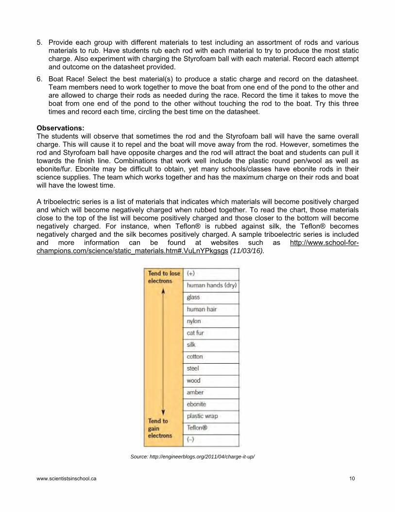
Observations: The students will observe that sometimes the rod and the Styrofoam ball will have the same overall charge. This will cause it to repel and the boat will move away from the rod. However, sometimes the rod and Styrofoam ball have opposite charges and the rod will attract the boat and students can pull it towards the finish line. Combinations that work well include the plastic round pen/wool as well as ebonite/fur. Ebonite may be difficult to obtain, yet many schools/classes have ebonite rods in their science supplies. The team which works together and has the maximum charge on their rods and boat will have the lowest time. A triboelectric series is a list of materials that indicates which materials will become positively charged and which will become negatively charged when rubbed together. To read the chart, those materials close to the top of the list will become positively charged and those closer to the bottom will become negatively charged. For instance, when Teflon® is rubbed against silk, the Teflon® becomes negatively charged and the silk becomes positively charged. A sample triboelectric series is included and more information can be found at websites such as http://www.school-for-champions.com/science/static_materials.htm#.VuLnYPkgsgs (11/03/16).
Source: http://engineerblogs.org/2011/04/charge-it-up/

www.scientistsinschool.ca 11
Discussion: The boat is powered by generating static electricity. The rod will be charged by rubbing it with a chosen material. The charged rod causes the boat to move in the water when it is placed near the Styrofoam ball. Generally, the students will discover that insulators, like balloons or plastic pens will hold the charge longer than conductors, like metals. Ask students if they can explain how this happens. Ask students what happened when they touched the rod or Styrofoam ball with their hand? The charge will dissipate. This occurs because the object is grounded by touching it with another object (i.e. a hand) and the object returns to neutral. Each atom consists of a nucleus containing positively charged particles surrounded by the same number of negatively charged electrons. Some substances contain neutral atoms and have no overall charge. When a rod is rubbed with another material, electrons can move from the one substance to the other in order to produce a negative charge on the object receiving the electrons and a positive charge on the object losing the electrons. Some substances have a weaker hold on their electrons and others have a stronger hold. The hold that the substance has on the electrons, illustrated by the triboelectric series, determines the type and amount of charge difference on the materials being rubbed together. For example, a balloon will become negatively charged when rubbed in hair because the electrons are transferred from the hair to the balloon. Extensions: 1. Using the charged rods, students can play a game of soccer using their desktop as the field. The
rods can be used to move the uncharged Styrofoam ball towards the opposite side of the desk in order to score a goal. The rods are not allowed to touch the ball. Note: if the ball is charged, it will “stick” to the desk surface.
2. Research how a balloon sticks to a wall after being rubbed on hair. Draw a series of pictures showing the stationary protons (+) and electrons (-) in the balloon, hair and wall to illustrate the movement of electrons before, during and after the balloon is rubbed in the hair.
3. Research and describe how static electricity is involved in a real life application, such as its use in photocopiers or when painting cars on an assembly line.
4. Determine what happens to an electroscope when a charged rod is brought close to it and also when a charged rod touches the electroscope. Draw a cartoon strip to illustrate the movement of the electrons along with the stationary protons in the leaves of the electroscope and the rod. Instruct half of the class to create a cartoon for a positively charged rod and the other half for a negatively charged rod. Students can exchange cartoon strips with a partner showing the oppositely charged rod and compare and contrast what happens.
Fun Fact: What Causes A Lightning Strike? Lightning is caused by an unbalanced electric charge in the
atmosphere. The movement of rain and ice particles inside a thundercloud creates an electric charge, with the negative charge
forming at the bottom of the cloud and the positive charge forming at the top. As opposites attract, the negative charge at
the bottom of the cloud will seek out a positive charge with which to connect. When lightning strikes the ground, it seeks out the shortest route to a structure with a positive charge, like a tree.

www.scientistsinschool.ca 12
Name: _________________
Static Boat Race
Type of Rod Material rubbed on rod
Material rubbed on Styrofoam ball
Observations: Movement of boat compared to rod
None Repulsion Attraction plastic pen ------------ ------------
plastic pen wool ------------
plastic pen ------------ wool
plastic pen wool wool
Our best combination of materials was _____________________________________
Times for boat race (circle best time): __________ __________ __________

www.scientistsinschool.ca 13
Activity 3: Living Circuit
3.
Time: 30-45 minutes Other Applications: drama, team building Key-terms: electron, cell, light bulb, conductor, series and parallel circuits Group Size: class Materials:
□ 75-100 paperclips or other small identical objects such as plastic coins or lego
□ 4 baskets to hold paperclips
□ skipping rope to represent circuit pathways: one short skipping rope and as many longer skipping ropes as needed to create a pathway for the class to follow; or alternatively, the activity could be done outside using sidewalk chalk
Learning Goal: The class will learn about series and parallel circuits through simulation. Electrical energy is the energy stored in charged particles. Circuits carry electric current in a closed loop and differ based on the physical layout of the pathways. A series circuit has all the parts of a circuit in a row and offers one pathway for the charge to move. A parallel circuit offers more than one pathway for the flow of electric charge. It is set up so that the current has an independent path through each piece of the circuit. There are two views in the electrical industry to describe electron movement:
● Conventional Current – This historical view is based on Benjamin Franklin’s discovery of electrical phenomena. Conventional current is described as current flow being from a positive terminal (anode) through the circuit into the negative terminal (cathode);
● Electron Flow - This view evolved after the discovery of electrons. Electrons, which have a negative charge, will want to move away from the negative end (anode) and move towards the positive end (cathode) of a cell. The direction of flow in an electric current can be thought of as opposites attracting. This is how the flow of charges is described in this activity.
Procedure: 1. Review with students the difference between series and parallel
circuits. Explain to students that this activity is a simulation of circuits that involves the whole class and can be considered a “living” circuit.
2. Explain to students that the simulation will make use of some everyday materials to represent parts of the circuit:
● “Charge” – represented by small identical objects, such as paperclips. Energy comes from a power source, such as the cell of a battery, and causes the electric charge to flow through the circuit.
● “Conductor Wires” – represented by skipping ropes, which will be laid on the ground, or chalk lines. The conductors permit the flow and indicate the direction or pathway of the electric charges.
Fun Fact: Why Don’t Birds Get Electrocuted? Birds that sit on one
power line will be safe as the circuit is
incomplete and birds are not good conductors
of electricity.

www.scientistsinschool.ca 14
Explain to the class the different roles that will be assigned:
● “Charges” (c) – Most students will be “charge” students. They will represent electric charge moving through the circuit. Each “charge” student will be passing along the energy object, such as paper clips, to move along the conductor wire.
● “Cells of a battery” ( ) – Two students will be “cells of a battery” to represent a power source. They will be holding baskets of paperclips. They will be handing out two paperclips to each charge student that moves past them.
● “Light Bulbs” ( ) – Two students will be assigned to be a “light bulb”. The light bulb is the load and uses the charge. The light bulb students will be standing on the conductor wire holding a basket. As the charge students pass, they will give the light bulb student their charge as represented by two paperclips. If the light bulb student puts their basket on the ground and stands on the pathway with their arms crossed, then this represents that the light bulb has blown out and the electric charge cannot move along.
The legend below provides descriptions of the symbols used in the following instructions for the class simulation and summarizes the roles to be played.
Symbol Part of Circuit Description of Role
c Electric charge The electric charge students move around the circuit.
Cell
The cells of the battery pass out two paperclips to each charge going by them.
Light bulb
The light bulbs take the two paperclips from each charge student passing by, unless they are burnt out.
Conductor wires
The charge path is represented by skipping ropes laid on the ground.
Direction
The arrows represent the direction of electric charge flow through the circuit.
Part A: Series Circuit (one pathway for electrons) Scenario 1 1. Fill two baskets with paperclips. The skipping rope will be used to create a pathway to represent a
series circuit. Lay down skipping rope to connect the cells of the battery and lights as in Figure 1.
2. Select two students to be the cells in the battery and give each of them a basket with the paper clips. Most of the remaining students will represent the “charge”. Each cell’s job will be to hand out two paper clips to each student charge as they pass by. This will result in each student charge receiving a total of four paper clips.
3. Select two other students to represent the light bulbs. Place these two students side by side, opposite to the battery, with a short skipping rope in between, holding empty baskets. The light bulb’s job will be to ensure that each student drops two paper clips into their baskets.
4. The remaining students will be the charge. As they enter the circuit, they will pick up two paper clips from each cell of the battery. Start the timer when the first student picks up their first two paper clips. The charge students then follow the rope. When they reach the light bulbs, they will drop off two paperclips in the first “light” basket, light “A”, and then count to 10 before moving to the next “light”, light “B”, where they will repeat the process. They will then continue back to the battery and pick up more paperclips and continue following the circuit as before.
5. Students will be moving continuously through the circuit.

www.scientistsinschool.ca 15
+
+
_
_
#1
#2 _
+
+ BA
_
6. Once the students have been around the circuit several times, within four to five minutes, stop the timer, and make a note of the time.
7. Have the “lights” count the number of paper clips in each of their baskets. Ask students if the light bulbs are equally lit.
Scenario 2 8. Ask students to freeze. Select one light bulb to be burnt out. Have the burnt out light bulb put their
basket down and stand with arms folded on the pathway. Ask students to continue the electron flow. Ask students what happens in a series circuit when one light bulb goes out.
Part B: Parallel Circuit (more than one pathway for electrons) Scenario 1 1. Set up with the same number of paperclips as the series circuit and with two students representing
the cells of the battery in the same position.
2. The two students who are the light bulbs will now be placed one in front of the other. Light bulb “A” will be in front of light bulb “B”. Set up the skipping ropes as in Figure 2.
3. Divide the remaining students into two groups with half of the students on team A and the other half on team B. Line the students so that they are in alternating order: A-B-A-B-A, etc.
4. As in the series circuit, when the charge students enter the circuit, they will pick up two paper clips from each cell of the battery. They will have a total of four paper clips from the cells of the battery. Start the timer when the first student picks up their first paper clips. Students who are on team “A” will put all four of their paper clips in the basket of light bulb “A”. Students on team “B” will put all four of their paperclips in the basket of light bulb “B”. Have the charge students count to 10 before they move on. There should always be a student at light bulb A and B.
5. Stop the activity after the same amount of time has elapsed as in the series circuit.
6. Count how many paperclips are in each “light” basket. Compare this number with the number from the series circuit. How much “charge” (paperclips) did the “lights” receive in each circuit? What would happen to the light bulbs in a real series vs. parallel circuit? What happens to the battery in a series vs. parallel circuit?
#1
A#2
B
Figure 1: Set up for series circuit, part A
Figure 2: Set up for parallel circuit, part B

www.scientistsinschool.ca 16
Scenario 2 Repeat the parallel circuit except this time whisper to one light bulb that they are burnt out. Have the burnt out light bulb put their basket down and stand with arms folded on the pathway. Ask students what happens in a parallel circuit when one light bulb goes out. Observations: Part A - Series Circuit Scenario 1: As each charge student travels along the path/conductor, they pick up paperclips from each cell student for a total of four paperclips. The charge student then gives half of the energy (two paperclips) to each light bulb student before moving along the path. The result is that both light bulbs are equally lit.
Scenario 2: When one light bulb is burnt out in a series circuit, the current stops. The circuit is open and as a result, the second light bulb will not be lit. The students between the cell and the burnt out light bulb will be stopped. The charge students that are past the burnt out light bulb will keep moving towards the cell students until eventually no-one can move and they are all physically stopped.
Part B - Parallel Circuit Scenario 1: As each charge student travels along the conductor wire, they pick up two paperclips from each cell student for a total of four paperclips. Each charge student will travel one of the two pathways and then drop off all four paper clips at the one light bulb.
Scenario 2: When one light bulb is burnt out in a parallel circuit, there is still another pathway through which the current can flow. The charge students that are on the path to the burnt out light bulb will be stopped. The second light bulb will receive the energy and will stay lit. Discussion: Ask students how their homes are wired. The light bulbs at home are wired in parallel so that when one light is turned off, the rest of the lights in the house can stay on. Ask students what happens when a bulb goes out on a string of holiday lights. The older holiday lights were wired as series circuits and when a bulb was blown, the entire string of lights did not work. Newer strings of holiday lights are wired in parallel circuits so that the rest of the lights will still operate when one bulb is blown. Notice that the number of paper clips in each “light basket” for the series circuit is about half of the number present for the parallel circuit. In a real series circuit, the light bulbs would appear dim, as the two light bulbs share the voltage from the battery. The “light baskets” in the parallel circuit contain approximately twice the paper clips of those in the series circuit. The light bulbs in the parallel circuit would be brighter, as each bulb can use the full voltage provided by the battery. Consequently, the parallel circuit would drain the battery much more quickly. Extensions: Break into smaller groups and challenge each group to determine how to simulate one of the challenge circuits provided below or create your own challenges. Have students draw a circuit diagram for their simulation (on paper or with chalk on the ground outside) and have each group present their circuit to the class. The class can then simulate the circuit. For each of the challenge circuit ideas included, ensure students pick up a total of three paperclips from three cells, instead of two.
Challenge Circuit Ideas:
1. Make a circuit containing three bulbs, a battery and a switch so that all bulbs turn off when the switch is open.
2. Make a circuit containing three bulbs, three switches, and a battery so that each bulb is controlled by one switch.
Challenge 1: Challenge 2:

www.scientistsinschool.ca 17
Activity 4: Electrical Circuit Game: Test Your Knowledge!
Time: 60-90 minutes Key Terms: any terms related to electricity and electrical devices such as static, electron, current, circuit, source, load, path, motor conductor, insulator, series, parallel, motor, generator, methods of generating electricity Group Size: 2-3 students Materials (per group):
□ “Electrical Circuit Game Worksheet”
□ “Electrical Circuit Game Template”
□ heavy cardboard larger than 8.5 x 11” template
□ glue and tape
□ 8 wires with alligator clips
□ mini bulb holder and 1.5V or higher mini bulb
□ “D” battery with battery holder
□ 10 brass paper fasteners
Learning Goal: The students will build a simple circuit and learn about the principles of electricity. Students will test their general knowledge of electricity. The premise for the game is similar to a matching game in that when the correct answer is chosen, the circuit will be closed and a bulb lights up. Procedure: 1. Each group of students will be assigned a topic about electricity
and make up five questions and answers to be used on their own quiz board. At the end, once the quiz boards are created and completed, each group will rotate through and test themselves as they try each of the circuit game boards.
2. Divide students into groups and provide each group with an “Electrical Circuit Game Worksheet”. Assign a topic to each group. Potential topic ideas include static electricity, components of a circuit, series circuits, parallel circuits, conductors vs. insulators, methods of generating electricity and energy conservation.
3. Have each group brainstorm questions and answers for their topic and record them on Step 1 of their worksheet.
4. Have the groups decide on their best five questions and answers for their assigned topic. Have them rewrite them on Step 2 of the worksheet. Ensure students are mixing up the answers in the second column to reflect how it will be on the finished version of the game.
5. Hand out the “Electrical Circuit Game Template”. Have students write the five questions neatly on the left hand side of the “Electrical Circuit Game Template”. The answers will be written one-by-one as they complete and test each circuit.
6. Provide each group with a set of materials and review a simple circuit. Have each group test the bulb, battery and each wire to ensure all components of their simple circuit are working.
7. Challenge students to make the “Electrical Circuit Game” quiz board with just the materials provided and no additional instructions. If necessary, continue following the procedure outlined below.
8. Have students glue or tape the template onto a slightly bigger piece of cardboard.
9. Have students poke the 10 brass fasteners within each circle on the template.
10. Using tape, secure the light bulb onto the cardboard template.

www.scientistsinschool.ca 18
11. Using the three wires with alligator clips, the light bulb and the battery, have students create an open circuit. Attach two wires to the light bulb. Attach one of those wires from the light bulb to the battery. Attach a third wire on the other side of the battery. The result is that the light bulb is connected to the battery and there are two wires to use to connect to brass fasteners of the questions and answers. The light bulb will only light up when the circuit is completed by the wire on the back of the cardboard which connects the correct answer to the question.
12. Using the other five wires with alligator clips, instruct the students to complete the “Electrical Circuit Game” quiz board. Have students write Answer #1 neatly in the appropriate spot on the template. Turn the cardboard lid over and use one of the wires with alligator clips to attach Question #1 to the fastener representing Answer #1. Have students test their first question and answer to ensure the simple circuit works and the light bulb is lit.
13. Repeat for the other four questions. Test each question and answer to ensure that each circuit is correctly hooked up and functional.
14. Place each “Electrical Circuit Game” quiz board around the classroom and have each group rotate and test themselves on each of the quiz boards made by the rest of the class.
Extensions: 1. Construct the “Electrical Circuit Game” game such that the battery is concealed in a box. Have
students attach the template onto a heavy cardboard box with a lid, such as a sturdy shoe or boot box. The light needs to be fixed onto the box using two metal paper clips that extend into the box. The following photo illustrates how the wires from the battery will be attached.
2. Construct an electrical circuit board using multiple choice questions instead of a matching question.

www.scientistsinschool.ca 19
Name (s): ______________________ ______________________
Electrical Circuit Game Worksheet Topic: ____________________
Step 1: Brainstorm questions and answers for your topic.
Question Answer
Step 2: Select the five best questions and answers. Rewrite them on this template copy so that answers are mixed up.
Question Answer Question #1: Answer #__:
Question #2: Answer #__:
Question #3: Answer #__:
Question #4: Answer #__:
Question #5: Answer #__:

www.scientistsinschool.ca 20
Name (s): ______________________ ______________________
Electrical Circuit Game Template Topic: ____________________
QUESTIONS ANSWERS

www.scientistsinschool.ca 21
Activity 5: Building a Battery-powered Car!
Time: 1-2 hours Other Applications: math Key-terms: series and parallel circuits, cells vs. batteries, diameter, axle Group Size: pairs Materials (per group):
□ 10 cm x 10 cm boxboard
□ ruler, compass, pencil
□ 1 bamboo skewer
□ 2 CDs
□ 5 water bottle caps
□ 2 straws, 20 cm long
□ 1 plastic mushroom tray
□ 6 wires: 2 x 30 cm and 4 x 8 cm – cut and strip off ends or use wires with alligator clips
□ 1 motor, minimum 1.5 V
□ 2 AA batteries (1.5 V)
□ clear packaging tape
□ glue & glue gun
□ scissors
□ “Build a Battery-powered Car!” datasheet
Learning Goal: The students will learn about differences between series and parallel circuits. A cell is a single unit that produces electricity from a chemical reaction. That energy is measured as volts (V). A battery is composed of either single cells (e.g. AA, AAA, C or D batteries) or multiple cells that are combined to get increased voltage (e.g. 9 V battery which contains six 1.5 V cells). Procedure: The car will have one front wheel and two rear wheels.
Part A: Front wheel and motor assembly 1. Using a compass, trace two circles, 4.5 cm in diameter, on the
boxboard. Cut these circles making them as smooth and circular as possible. These will form the single front wheel.
2. Using the pointed tip of the skewer, carefully poke a hole through the centre of each boxboard circle. Poke a hole through the centre of one of the bottle caps. Place one boxboard circle, then the bottle cap and then the other boxboard circle onto the skewer in order to keep the holes centred. Glue the three pieces together. Once dry, remove this “front wheel” from the skewer and glue onto the axle of the motor.
3. Attach a 30 cm length of wire to each connection on the motor.
4. Cut out the middle 3 cm from the front of the plastic mushroom tray. Tape the motor inside the front of the tray such that the wheel can turn freely within this cut out section. The motor may need to be supported by taping two short pieces of straws between the motor and the bottom of the tray.
5. Using the point of the skewer, poke one hole in the side of the tray and insert one length of wire. Poke a second hole in the bottom of the tray and insert the second length of wire.
6. Due to the weight of the motor, the tray will need to be reinforced using a straw cut to the width of the bottom of the tray and then taped across the tray near the front where the wheel is placed.
Step 1 - 2: Cardboard front wheel assembly with plastic bottle cap in centre
Step 3 - 5: Motor with two pieces of
30 cm wire attached
Step 6: Reinforced tray using a straw
Part A: Front Wheel & Motor Assembly

www.scientistsinschool.ca 22
Part B: Rear wheels and axle assembly 7. The rear axle will run along the back of the tray. Use a ruler and pen to mark the position where
the rear axle will go. Make a mark on both sides of the tray, 1 cm from the bottom and 2 cm from the back edge. Using the tip of the skewer, poke a hole on either side of the back of the tray where these points have been marked.
8. Place the straw through these holes and trim the straw so that the straw extends 1 cm beyond the largest width of the tray. This will ensure that the wheels do not rub against the tray.
9. Using the skewer, poke a hole through the centre of each of the four water bottle caps.
10. Assemble the rear wheels on the axle so that the open sides of each of two bottle caps face each other with a CD in between. To do this, place the skewer on the desk so that the tip faces up, add one bottle cap open side up, then the CD, then the second bottle cap open side down. Push the entire wheel assembly down, leaving 2 cm of skewer at the bottom. Place the skewer through the straw in the car. Push the third bottle cap open side up onto the skewer, then the CD, then the fourth bottle cap open side down. Cut off the sharp end of the skewer so that there is 2 cm of skewer remaining at the top. If these wheels are not sturdy enough, add glue between the bottle caps and CDs.
Part C: Attaching the Batteries 11. Turn the tray upside down so that the bottom of the tray forms the top of the car.
12. Pick up the car so that the front wheel is free to move. Using one of the batteries, touch the wires which are coming through the tray from the motor to the battery to determine the direction of spin of the front wheel. This step is important so that when the wires are all connected it will ensure that the front wheel will pull the car forward.
13. Using a pair of scissors, strip the ends of the four wires so that the length of each wire is 8 cm. Tape one wire to the end of each of the two batteries. Pick up the car to do this step so that the front wheel is free to move. Test that the batteries and wires are working, by touching the wires to those attached to the motor to ensure the motor turns.
14. Using clear packing tape, attach the two batteries onto the top of the car/tray.
Part B: Rear Wheel & Axle Assembly
Step 7 - 9: Placement of axle using the
skewer and straw
Step 10: Assembly of rear wheels using
CD and water bottle caps
Part C: Attaching the Cells Step 11 - 14
www.scientistsinschool.ca 23
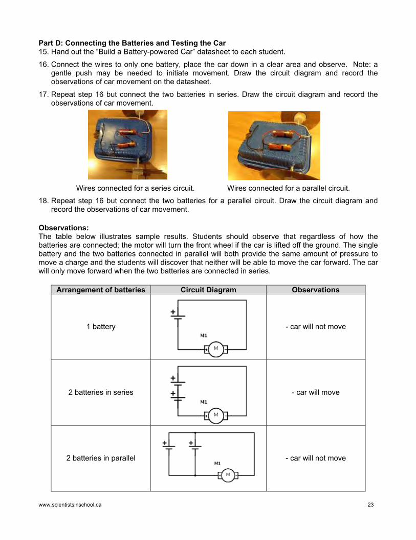
Part D: Connecting the Batteries and Testing the Car 15. Hand out the “Build a Battery-powered Car” datasheet to each student.
16. Connect the wires to only one battery, place the car down in a clear area and observe. Note: a gentle push may be needed to initiate movement. Draw the circuit diagram and record the observations of car movement on the datasheet.
17. Repeat step 16 but connect the two batteries in series. Draw the circuit diagram and record the observations of car movement.
18. Repeat step 16 but connect the two batteries for a parallel circuit. Draw the circuit diagram and
record the observations of car movement. Observations: The table below illustrates sample results. Students should observe that regardless of how the batteries are connected; the motor will turn the front wheel if the car is lifted off the ground. The single battery and the two batteries connected in parallel will both provide the same amount of pressure to move a charge and the students will discover that neither will be able to move the car forward. The car will only move forward when the two batteries are connected in series.
Arrangement of batteries Circuit Diagram Observations
1 battery - car will not move
2 batteries in series - car will move
2 batteries in parallel
- car will not move
Wires connected for a series circuit. Wires connected for a parallel circuit.

www.scientistsinschool.ca 24
Discussion Ask students to explain why their cars did not move when they were connected to only one battery. When one battery is connected, it provides 1.5 V which is not enough to move the car.
Ask students to explain why their cars did not move when they were connected in parallel to two batteries. When the batteries are connected in parallel, the voltage stays the same at 1.5 V which will not be enough to move the car forward. Each electron either gets a push from one battery or the other when connected in parallel.
Ask students why their car moved when it was connected in series. By combining the batteries in series, this increases the voltage. When the batteries are connected in series, each electron receives a push from each battery and the voltage adds to a total of 3.0 V which will be enough to make the car move. Extensions: 1. Additional cells or batteries may be added in series or parallel to solidify understanding. Do not
connect too many batteries as this may be too much for the motor. For example, for a 3V motor and 1.5V batteries, 1, 2 or 3 batteries can be briefly tested in series and parallel. Discuss with students the impact that the number of energy cells has on a motor. For example, in series, a motor may operate on less voltage but will turn more slowly and eventually put stress on the motor. At higher voltage, the motor will speed up and eventually seize up. In parallel, the voltage does not change but the motor may operate for a longer time.
2. The car may be converted to solar power by using solar cells instead of batteries. The solar panel needs to be for the same voltage that is required by the motor. Direct sunlight is necessary and therefore this activity should be done outdoors on a sunny day.
3. Students could use their own materials to design and build even better cars (eg. lighter, less friction) which could be raced against one another.
4. Have students research solar powered vehicles which are designed and built by university students. For example, the Midnight Sun Solar Rayce Car Team, affiliated with the University of Waterloo, competes in the American Solar Challenge in the United States and the World Solar Challenge, held in Australia. https://uwaterloo.ca/sedra-student-design-centre/directory-teams/midnight-sun-solar-rayce-car-team (11/03/16)
Fun Fact: The Sun - A Renewable Energy Source
Solar energy has been used by humans for a long time for heating, cooking food, removing salt from
seawater and drying clothes. In 1953, Fuller, Pearson & Chapman discovered
the silicon solar cell. Although an expensive option at the time, technological advances have
decreased solar power costs today and it has become a viable alternative, competing with non-renewable
energy sources such as coal and oil.

www.scientistsinschool.ca 25
Name: _________________
Build a Battery-powered Car!
Arrangement of batteries Circuit Diagram Observations
1 battery
2 batteries connected in series
2 batteries connected in parallel

www.scientistsinschool.ca 26
Teacher Resources Literary Resources
Electricity (Science Alive!). Darlene Lauw and Lim Cheng Puay. 1997. Crabtree Publishing. ISBN: 0-7787-0561-7. Excellent easy experiments and explanations about electricity. Electricity (Real Scientist Investigates). Peter Riley. 2011. Sea to Sea Publications. ISBN: 978-1-59771-279-8. Background information, an activity with expected results, and real life application on every page. Website Resources
http://www.allaboutcircuits.com/ (11/03/16) A collection of online textbooks. http://www.physicsclassroom.com/ (11/03/16) An excellent resource of information in easy-to-understand language. http://www.enwin.com/kids/electricity/ (11/03/16) A kid and teacher friendly overview of electricity and interesting facts. http://www.regentsprep.org/Regents/physics/phys03/aeleclab/nerscope.htm (11/03/16) Excellent animation showing both a positive and a negative rod moving towards an electroscope. http://www.technologystudent.com/energy1/engex.htm (11/03/16) A comprehensive collection of information about alternative energy sources. http://science.sbcc.edu/~physics/solar/sciencesegment/ (11/03/16) Excellent explanation of how a solar cell works. http://pbskids.org/designsquad/parentseducators/resources/index.html?category=electricity (11/03/16) Excellent website with extensive resources for teachers. http://www.need.org/files/curriculum/guides/ElectroWorks%20Teacher.pdf (11/03/16) An excellent resource for hands-on activities and background information related to electricity. http://www.digikey.com/schemeit (11/03/16) A great website to create schematic circuit diagrams. http://courseweb.stthomas.edu/apthomas/SquishyCircuits/ (11/03/16) A website covering how to make circuits using insulating and conductive dough. http://www.opg.com/communities-and-partners/teachers-and-students/Pages/teachers-and-students.aspx (11/03/16) Resources to teach about electrical energy and electricity generation. Interactive White Board Resources
“Electrical Circuits” http://exchange.smarttech.com/details.html?id=fab2c48a-8ef7-4d62-8097-52787e51ad5b (11/03/16) Review the law of charges and review the series and parallel circuits. “Electricity Unit” http://exchange.smarttech.com/details.html?id=9fd518f6-47c0-41fe-bbef-2d214443d7b1 (11/03/16) A detailed review of how and why electricity works.

www.scientistsinschool.ca 27
Multi-media Resources
http://www.youtube.com/watch?v=gixkpsrxk4Y 6:49 min (11/03/16) “Electricity – Bill Nye the Science Guy”. Bill Nye thoroughly discusses electricity. The following websites provide a sampling of detailed instructions for building various electrical-related projects that could be used as class demonstrations: http://www.youtube.com/watch?v=SzQ2EZ0HPuY 6:44 min (11/03/16) Building a simple electroscope. http://www.youtube.com/watch?v=FITxr6bJmd8 7:37 min (11/03/16) Making a potato battery. http://www.youtube.com/watch?v=DXir_ORHOGA 4:01 min (11/03/16) Making a lemon battery. http://www.youtube.com/watch?v=eJ1e2Lj_tsQ 5:25 min (11/03/16) Making a voltaic pile. http://www.youtube.com/watch?v=elFUJNodXps 9:36 min (11/03/16) Building an electric motor.
Student Resources Literary Resources
The Magic School Bus and the Electric Field Trip. Joanna Cole. 1997. Scholastic Inc. ISBN-13: 978-0-590-44683-9. Join Ms. Frizzle and her class as they learn how electricity is generated by burning fuel, moving through a turbine and generator in the power plant and then along the transmission lines and into various appliances, including a light bulb, a toaster, an electric motor and school. Time for Kids Biographies: Thomas Edison: A Brilliant Inventor. Lisa DeMauro. 2005. HarperCollins Publishers Inc. ISBN: 0-06-057611-1. An easy to read, excellently illustrated book about Thomas Edison, his life and inventions. Interactive Websites
http://eec.electricuniverse.com/ (11/03/16) Explore the “Electric Universe” and discover games and activities related to electricity. http://kids.saveonenergy.ca (11/03/16) Kids Corner is a great website with student friendly information, games and other fun facts about electricity and its wise use. Also in French. http://kidsenergyzone.com/ (11/03/16) Energy facts, history, safety and fun activities for kids. http://phet.colorado.edu/en/simulations/category/physics/electricity-magnets-and-circuits (11/03/16) A series of fun interactive simulations of different electricity concepts (e.g. static electricity, circuits). References In addition to resources listed above, the following websites were also used to develop this package: http://en.wikipedia.org/wiki/Electricity (07/01/13); http://assets.wwf.ca/downloads/sweaterday_trivia.pdf (09/01/13); http://www.world-nuclear.org/info/Country-Profiles/Countries-A-F/Canada--Nuclear-Power/ (09/01/13); http://www.cna.ca/nuclear_facts/electrical_power/ (09/01/13); http://www.thefreedictionary.com/static+electricity (15/12/13); http://www.dummies.com/how-to/content/how-batteries-work-in-electronic-circuits.html (06/01/14); http://en.wikipedia.org/wiki/Electric_current (15/12/13); http://en.wikipedia.org/wiki/Static_electricity (15/12/13); http://en.wikipedia.org/wiki/Voltage (06/01/14); http://www.rapidtables.com/convert/electric/watt-to-wh.htm (31/03/14); http://generation.synergy.net.au/sites/default/files/electricity_fun_facts_0.pdf (23/06/14); http://www.fplsafetyworld.com/?ver=kkblue&utilid=fplforkids&id=16188 (23/06/14); http://theenergycollective.com/sbattaglia/203061/earth-hour-2013-results-are (31/03/14); http://www.sciencekids.co.nz/sciencefacts/weather/lightning.html (24/06/13); http://generation.synergy.net.au/sites/default/files/electricity_fun_facts_0.pdf (23/06/14); https://www.experience.com/alumnus/article?channel_id=energy_utilities&source_page=additional_articles&article_id=article_1130427780670 (14/03/16); http://www.sciencekids.co.nz/sciencefacts/energy/solarpower.html (14/03/16).

Get kids excited about science
Science Education Through Partnership Scientists in School is a leading science education charity that reaches more Kindergarten to Grade 8 youth than any other science non‐profit in Canada – more than 700,000 in the 2018‐19 school year. Through our hands‐on, inquiry‐based science, technology, engineering, math (STEM) and environmental classroom and community workshops, we strive to ignite scientific curiosity in children so that they question intelligently; learn through discovery; connect scientific knowledge to their world; get excited about science, technology, engineering and math; and have their interest in careers in those fields piqued. By making science a verb ‐ something you do ‐ our workshops allow children’s natural curiosity to reign, inspire kids to see themselves as scientists and engineers, and make connections between science and the world around them. This sets the stage for a scientifically‐literate future generation who will fuel Canada’s economic prosperity and think critically about the scientific challenges facing our society. Scientists in School relies upon corporate, community, government and individual donors, as well as school board partners for support to develop new programs, continuously improve our existing programs, reach new geographic areas, provide complimentary workshops to less‐privileged schools, and subsidize the cost of every one of our 24,872 annual classroom workshops.
Our Partners Catalyst Level:
Natural Sciences and Engineering Research Council of Canada, TD Friends of the Environment Foundation
Innovation Level: Amgen Canada, John and Deborah Harris Family Foundation, Nuclear Waste Management Organization,
Ontario Power Generation, Toronto Pearson International Airport
Imagination Level: ArcelorMittal Dofasco, General Motors Canada, McMillan LLP, Superior Glove Works Ltd., TELUS
Discovery Level:
Alectra Utilites, Aviva Community Fund, Cadillac Fairview, CAE, Cameco Corporation, Canadian Nuclear Safety Commission, Carolyn Sifton Foundation, Celestica, Hamilton Community Foundation, MilliporeSigma,
Modern Niagara, Niagara Community Foundation, Pendle Fund at the Community Foundation of Mississauga, Purdue Pharma, S.M. Blair Family Foundation, Society of Petroleum Engineers Canadian Educational
Foundation, Syngenta Canada Inc., Systematix Inc., The McLean Foundation
Exploration Level: Ajax Community Fund at Durham Community Foundation, Brant Community Foundation, Cajole Inn Foundation
City of Brantford, Community Foundation Grey Bruce, Dwight and Karen Brown Family Fund – Ottawa Community Foundation, Elexicon Energy, LabX Media Group Charity Fund at the Huronia Community Foundation, Siemens Milltronics Process Instruments, The Community Foundation of Orillia and Area,
The County of Wellington, The Source, The Township of Tiny, Whitby Mayor’s Community Development Fund
[email protected] – www.scientistsinschool.ca Scientists in School is a registered Canadian charity: #867139537RR0001