electricalclass
TRANSCRIPT

1
PinspotterPinspotterPinspotter
AMF Pinspotter Electrical Troubleshooting and Repair Seminar
April 18, 2007
Presented by
and
Bowl New England

2
Electrical Seminar Electrical Seminar Electrical Seminar Electrical Seminar Objectives:Objectives:Objectives:Objectives:
• Follow safety standards and procedures
• Troubleshoot efficiently • Use a meter to test Volts, Ohms & Amperes
• Crimp terminals • Solder and desolder wire • Understand AMP terminals • Know current QubicaAMF electrical parts & tools

3
Safety First! Always remove main R-S Plug first Use proper Lockout/Tagout procedures Inform coworkers and be aware Put everything back when done Amperage necessary to kill you:
______________________________ Name 2 safety items wrong in the top picture
1. ____________________________ 2. ____________________________
The Trouble Call: Pinspotter will not cycle List 10 possible causes of this problem below

4
Thanks to www.doctronics.co.uk
Understanding Electricity and Basics of using a Multimeter
A meter is a measuring instrument. An ammeter measures current, a voltmeter measures the potential dif-ference (voltage) between two points, and an ohmmeter measures resistance. A multimeter combines these functions, and possibly some additional ones as well, into a single instrument. Before going in to detail about multimeters, it is important for you to have a clear idea of how meters are con-nected into circuits. Diagrams A and B below show a circuit before and after connecting an ammeter:
Think about the changes you would have to make to a practical circuit in order to include the ammeter. To start with, you need to break the circuit so that the ammeter can be connected in series. All the current flow-ing in the circuit must pass through the ammeter. Meters are not supposed to alter the behavior of the circuit, or at least not significantly, and it follows that an ammeter must have a very LOW resistance. Diagram C shows the same circuit after connecting a voltmeter:
This time, you do not need to break the circuit. The voltmeter is connected in parallel between the two points where the measurement is to be made. Since the voltmeter provides a parallel pathway, it should take as little current as possible. In other words, a voltmeter should have a very HIGH resistance.
A
B
to measure current, the circuit must be broken to allow the
ammeter to be connected in series
ammeters must have a LOW resistance
A
C
to measure potential difference (voltage), the circuit is not changed:
the voltmeter is connected in parallel
voltmeters must have a HIGH resistance

5
Which measurement technique do you think will be the more useful? In fact, voltage measurements are used much more often than current measurements. The processing of electronic signals is usually thought of in voltage terms. It is an added advantage that a voltage measurement is easier to make. The original circuit does not need to be changed. Often, the meter probes are connected simply by touching them to the points of interest.
What does DC mean? DC means direct current. In any circuit which operates from a steady voltage source, such as a battery, current flow is always in the same direction. It is indicated by the symbol
AC means alternating current. In an electric lamp connected to the domestic mains elec-tricity, current flows first one way, then the other. That is, the current reverses, or alter-nates, in direction. In the United States, the current reverses 60 times per second. It is indicated by the symbol
An ohmmeter does not function with a circuit connected to a power supply. If you want to measure the resis-tance of a particular component, you must take it out of the circuit altogether and test it separately, as shown in diagram D:
Ohmmeters work by passing a small current through the component and measuring the voltage produced. If you try this with the component connected into a circuit with a power supply, the most likely result is that the meter will be damaged. Most multimeters have a fuse to help protect against misuse. The mathematical relationship between the three measures is “Ohm’s Law:” VOLTS = AMPS x OHMS.
A
D
to measure resistance, the component must be removed from the circuit altogether
ohmmeters work by passing a current through the component being tested
Testing Capacitors
Ω
∞ 0 Capacitors are used to provide a “blast” of energy for all pinspotter motors when they are starting. Combo (Sweep and Table) motors also use capacitors to help stop the motor in an exact position. Sometimes capacitors get weak or fail altogether. Capacitors are suspect if a motor __________________________, __________________________ or __________________________. You discharge a capacitor by _______________across the terminals. Draw the test meter’s probes in the picture at right. If the capacitor is good, draw the needle where it starts out How long should it take for the needle to move across the scale?____ If a capacitor tests good, it still might not work properly. True False
6
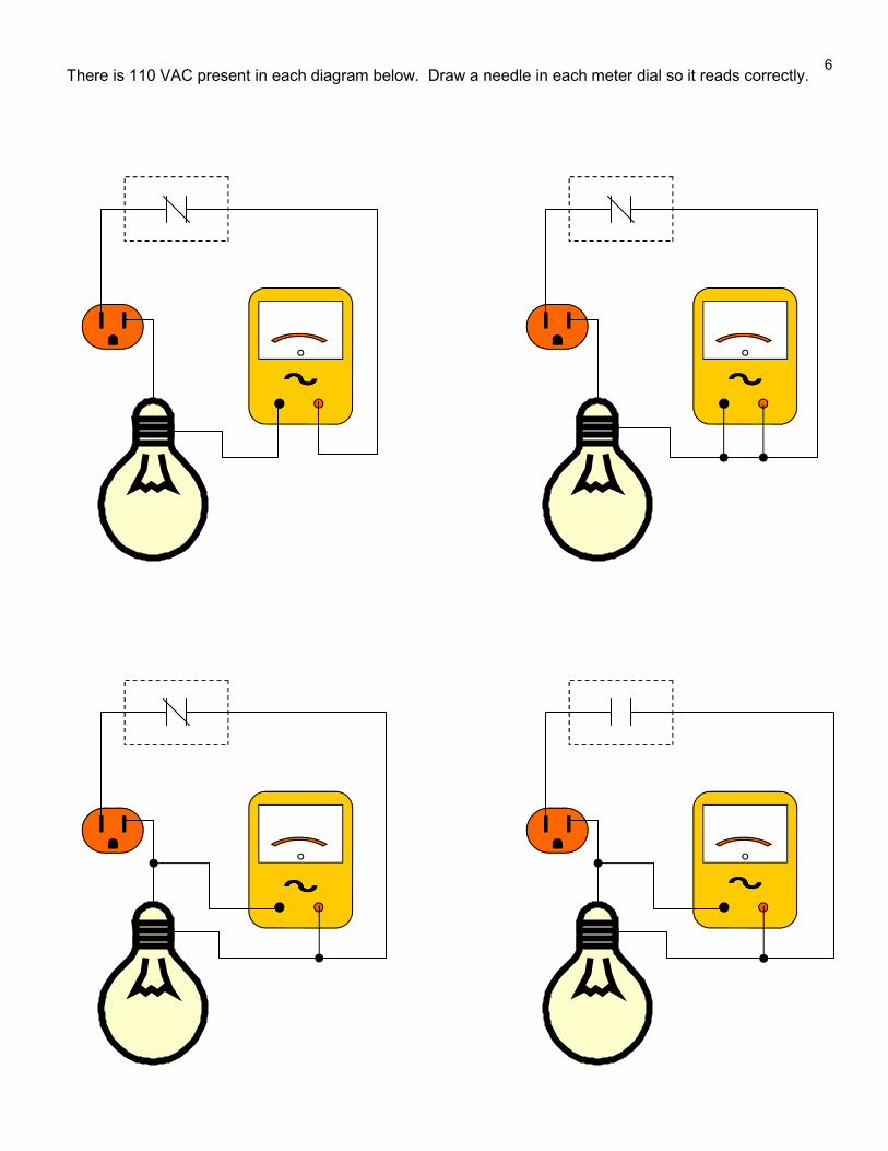
There is 110 VAC present in each diagram below. Draw a needle in each meter dial so it reads correctly.
7
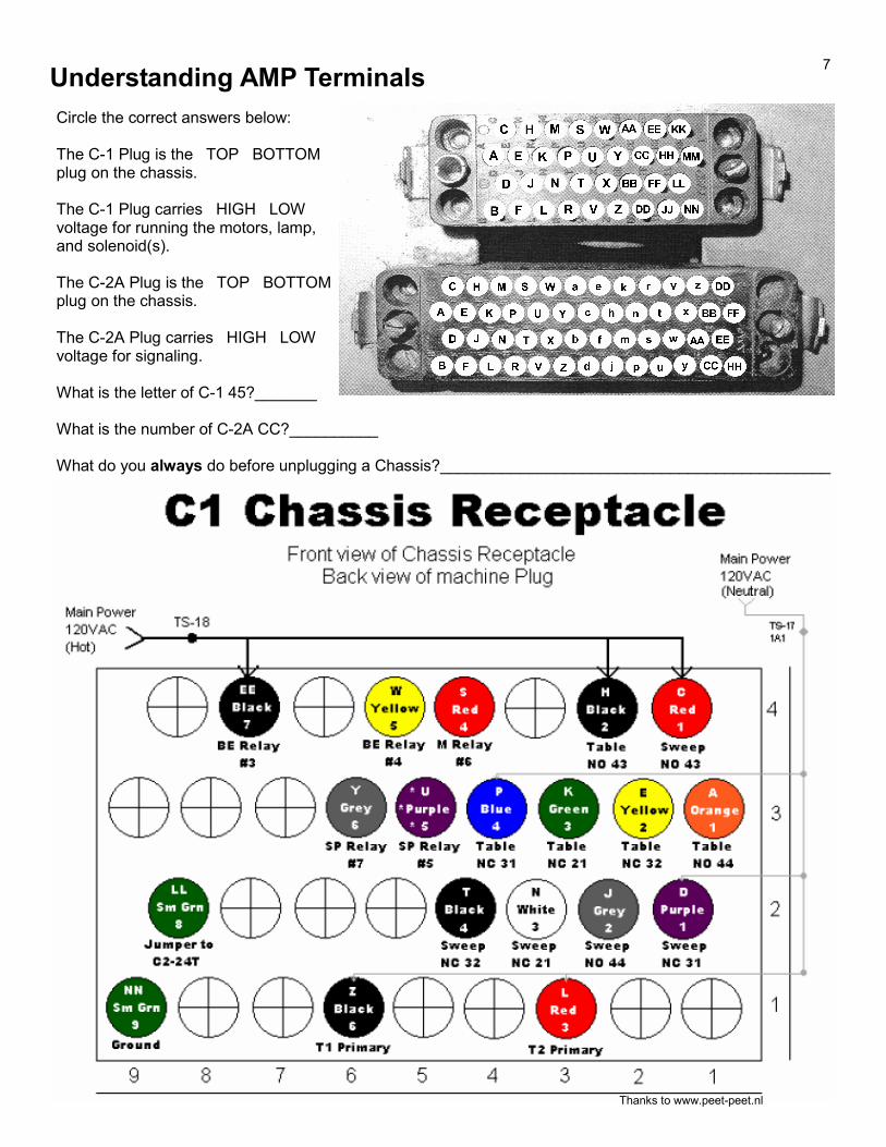
Understanding AMP Terminals
Circle the correct answers below: The C-1 Plug is the TOP BOTTOM plug on the chassis. The C-1 Plug carries HIGH LOW voltage for running the motors, lamp, and solenoid(s). The C-2A Plug is the TOP BOTTOM plug on the chassis. The C-2A Plug carries HIGH LOW voltage for signaling. What is the letter of C-1 45?_______ What is the number of C-2A CC?__________ What do you always do before unplugging a Chassis?____________________________________________
Thanks to www.peet-peet.nl
8
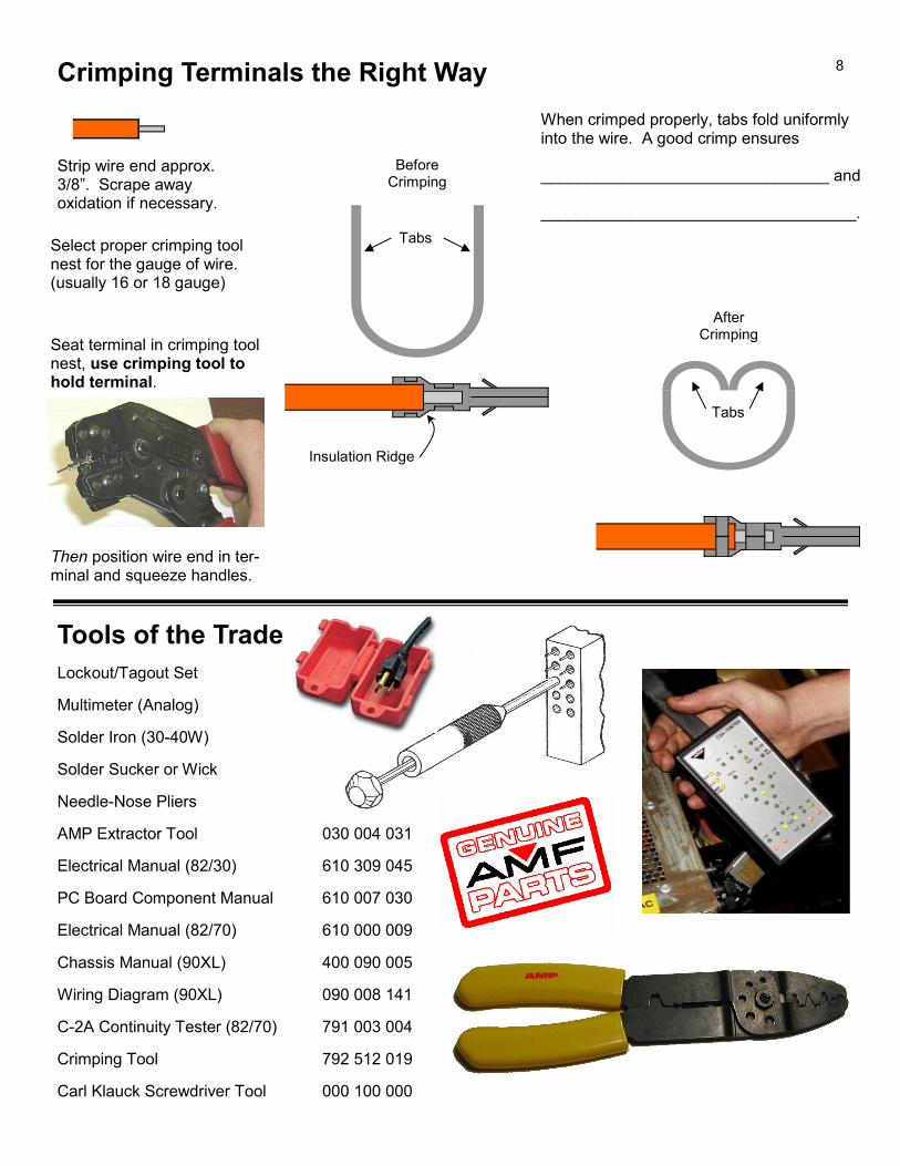
Crimping Terminals the Right Way
Tools of the Trade
Lockout/Tagout Set
Multimeter (Analog)
Solder Iron (30-40W)
Solder Sucker or Wick
Needle-Nose Pliers
AMP Extractor Tool 030 004 031
Electrical Manual (82/30) 610 309 045
PC Board Component Manual 610 007 030
Electrical Manual (82/70) 610 000 009
Chassis Manual (90XL) 400 090 005
Wiring Diagram (90XL) 090 008 141
C-2A Continuity Tester (82/70) 791 003 004
Crimping Tool 792 512 019
Carl Klauck Screwdriver Tool 000 100 000
Strip wire end approx. 3/8”. Scrape away oxidation if necessary.
Seat terminal in crimping tool nest, use crimping tool to hold terminal.
Then position wire end in ter-minal and squeeze handles.
When crimped properly, tabs fold uniformly into the wire. A good crimp ensures ________________________________ and ___________________________________.
Before Crimping
After Crimping
Insulation Ridge
Tabs Select proper crimping tool nest for the gauge of wire. (usually 16 or 18 gauge)
Tabs

9
Soldering: Tips and General Instructions
Good soldering is a skill that is learned by practice. The most important point in soldering is that both parts of the joint to be made must be at the same temperature. The solder will flow evenly and make a good electrical and mechanical joint only if both parts of the joint are at an equal high temperature. Even though it appears that there is a metal to metal contact in a joint to be made, very often there exists a film of oxide on the sur-face that insulates the two parts. For this reason it is no good applying the soldering iron tip to one half of the joint only and expecting this to heat the other half of the joint as well.
When the iron is hot, apply some solder to the flattened working end at the end of the bit, and wipe it on a piece of damp cloth or sponge so that the solder forms a thin film on the bit. This is tinning the bit.
Melt a little more solder on to the tip of the soldering iron, and put the tip so it contacts both parts of the joint. It is the molten solder on the tip of the iron that allows the heat to flow quickly from the iron into both parts of the joint. If the iron has the right amount of solder on it and is positioned correctly, then the two parts to be joined will reach the solder's melting temperature in a couple of seconds. Now apply the end of the solder to the point where both parts of the joint and the soldering iron are all touching one another. The solder will melt immediately and flow around all the parts that are at, or over, the melting part temperature. After a few sec-onds remove the iron from the joint. Make sure that no parts of the joint move after the soldering iron is re-moved until the solder is completely hard. This can take quite a few sec-onds with large joints. If the joint is disturbed during this cooling period it may become seriously weakened.
The hard cold solder on a properly made joint should have a smooth shiny appearance and if the wire is pulled it should not pull out of the joint. In a properly made joint the solder will bond the components very strongly indeed, since the process of soldering is similarly to brazing, and to a lesser degree welding, in that the solder actually forms a molecular bond with the surfaces of the joint.
It is important to use the right amount of solder, both on the iron and on the joint. Too little solder on the iron will result in poor heat transfer to the joint, too much and you will suffer from the solder form-ing strings as the iron is removed, causing splashes and bridges to other contacts. Too little solder applied to the joint will give the joint a half finished appearance: a good bond where the soldering iron has been, and no solder at all on the other part of the joint.
Remember it is much more difficult to correct a poorly made joint than it is to make the joint properly in the first place. Anyone can learn to solder, it just takes practice. Thanks to www.irational.org

10
Project: MAKE YOUR OWN DIAGNOSTIC TOOL This tool will help you troubleshoot manager control and cycle command problems. You will need wire, electrical tape, some AMP pin and socket type terminals, an AMP 14-position connector block, solder, a soldering iron and sponge, a wire dike/stripper, and an AMP crimping tool. INSTRUCTIONS: Step 1. Cut two 6” lengths of PINK 18ga. stranded wire Cut one 6” length of WHITE 18ga. stranded wire Cut one 6” length of BLACK 18ga. stranded wire Step 2. Strip 3/16” of insulation from both ends of the BLACK wire. Strip 3/16” of insulation from both ends of the WHITE wire. Strip 3/16” of insulation from one end and 3/8” of insulation from the other end of both PINK wires Step 3. Crimp AMP pin terminals on the 3/16” stripped ends of both PINK wires Crimp AMP pin terminals on both ends of the BLACK wire Crimp an AMP pin terminal on one end and an AMP socket terminal on the other end of the WHITE wire Step 4. Install the PINK wire pins in terminals 21B and 22E of the A&MC plug Install one BLACK wire pin in terminal 13H of the A&MC plug Install the WHITE wire pin in terminal 14L of the A& MC plug Step 5. Solder the 3/8” stripped ends of the PINK wires together and wrap the joint with tape.