electrical workshop module 4: study of measurement & test equipment (2- weeks)
DESCRIPTION
Institute Of Applied Technology ATE 1012 Grade 10. Electrical Workshop Module 4: Study of Measurement & Test Equipment (2- weeks). Module Objectives. Be familiar with the usage of Multi-meters, Oscilloscopes and Function Generators - PowerPoint PPT PresentationTRANSCRIPT

Electrical Workshop Module 4:
Study of Measurement &Test Equipment
(2-weeks)
Institute Of Applied TechnologyATE 1012Grade 10
Eng. Rose Hasan
Eng. Rose Hasan
Module Objectives
Be familiar with the usage of Multi-meters, Oscilloscopes and Function Generators
Perform Measurements of electrical quantities using measuring instruments
Test diodes and connectivity
Module Contents
Introduction Multimeter
Voltage Measurement Current Measurement Resistance Measurement
Diode Testing Continuity Test Function Generator Oscilloscope Practical Tasks
Eng. Rose Hasan

Introduaction Measuring and Test Equipment are used to:
measure electrical quantities test electrical components generate different types of signals to test the
response of the circuit to that signal. Measuring and test equipment can be used
to: troubleshoot electrical problems in many
industrial and household devices such as batteries, lamps, motor controls and wiring systems
Eng. Rose Hasan

Eng. Rose Hasan
Measurement & test equipment functions

Eng. Rose Hasan
Multimeters
Purpose: A multi-meter is an electronic measuring instrument that combines several functions in one unit. It is used to: measure voltage, current and resistance
and to test diodes and connectivity

Eng. Rose Hasan
Multimeter Functions

MultimeterTypes: There are two
types of multimeters: analog & digital
Eng. Rose Hasan

Eng. Rose Hasan
Multimeter circuit symbols

Eng. Rose Hasan
Digital Multimeter Measurements: Voltage Measurements
Voltage Measurement (Voltmeter): To measure the DC voltage across electrical components in a circuit, follow these steps: Select on the digital multi-
meter's setting switch on the largest voltage range.
Connect the positive (RED) (+) lead to the part of the circuit that is connected to the positive (+) side of the supply (battery).

Digital Multimeter Measurements
Connect the negative (BLACK) (-) lead to the part of the circuit that is connected to the negative (-) side of the supply (battery).
Switch on the multi-meter by pressing "POWER" button. Then select the best range that will give you the most accurate results.
Record the reading and the unit that are displayed in the multimeter's display.
Eng. Rose Hasan
http://serc.carleton.edu/sp/compadre/interactive/examples/19095.htmlhttp://www.physics-chemistry-interactive-flash-animation.com/electricity_electromagnetism_interactive/multimeter.htm

Eng. Rose Hasan
Practical Tasks: Activity1: Battery Tester Items Required:

Eng. Rose Hasan
Battery Tester, Steps:
Measure the voltage across the batteries using a multi-meter:

Eng. Rose Hasan
Results:
Record your readings on the following table. The true value is the value written on the battery

Results:
3. Compare the measured value with the true value of the voltage written in the battery. Is the measured value close to the real value? If no, state why? ______________________________________
4. You can test a battery using Multi-meter by: (a) Voltage measurement (b) Connectivity test (c) Diode Test
Eng. Rose Hasan
Digital Multimeter Measurements: Current Measurements
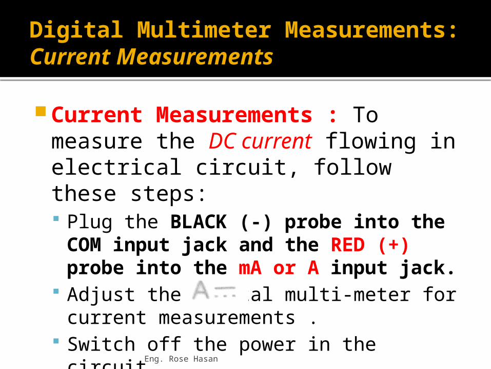
Current Measurements : To measure the DC current flowing in electrical circuit, follow these steps: Plug the BLACK (-) probe into the
COM input jack and the RED (+) probe into the mA or A input jack.
Adjust the digital multi-meter for current measurements .
Switch off the power in the circuit.Eng. Rose Hasan

Eng. Rose Hasan
Digital Multimeter Measurements: Current Measurements
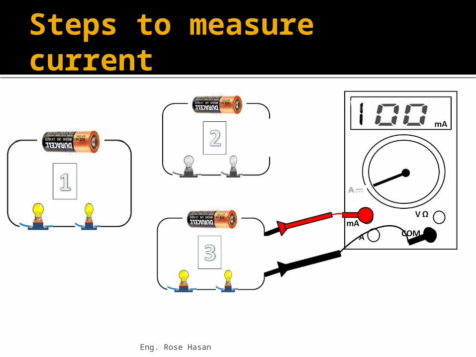
Break the circuit between elements where the current to be measured.
Insert the probes of the multi-meter in the place where do you break the circuit.
Switch on the multi-meter. Select the best range that will give you
the most accurate results. Record the reading and the unit that are
displayed in the multi-meter's display
Eng. Rose Hasan
Steps to measure current
Digital Multimeter Measurements: Resistance Measurements
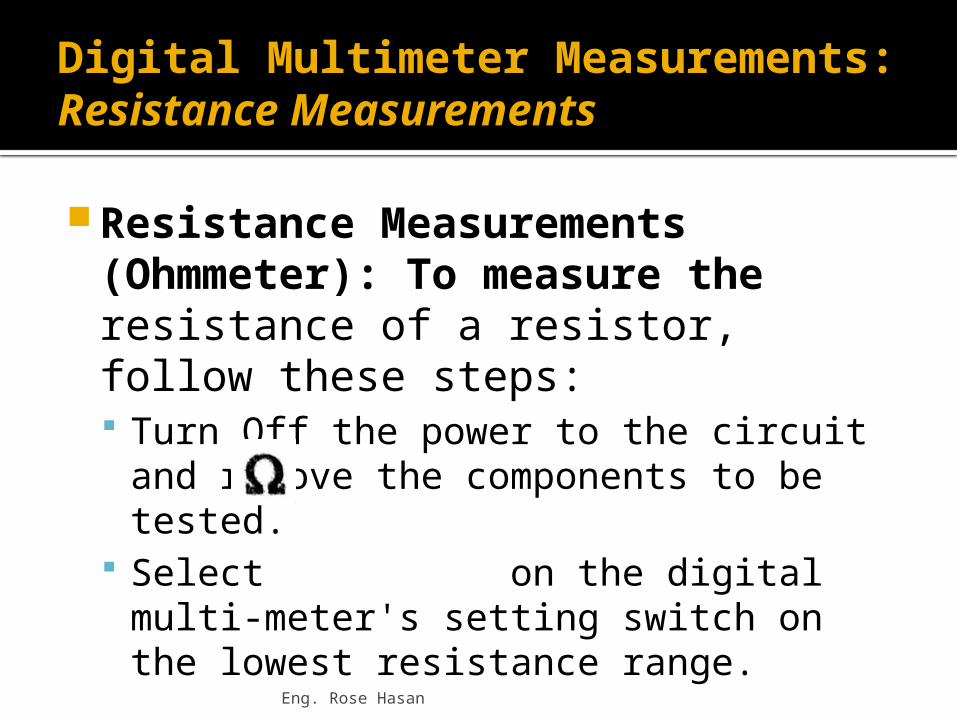
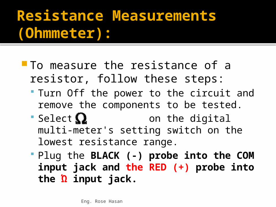
Resistance Measurements (Ohmmeter): To measure the resistance of a resistor, follow these steps: Turn Off the power to the circuit and
remove the components to be tested. Select on the digital multi-meter's
setting switch on the lowest resistance range.
Eng. Rose Hasan
Resistance measurement using multimeter
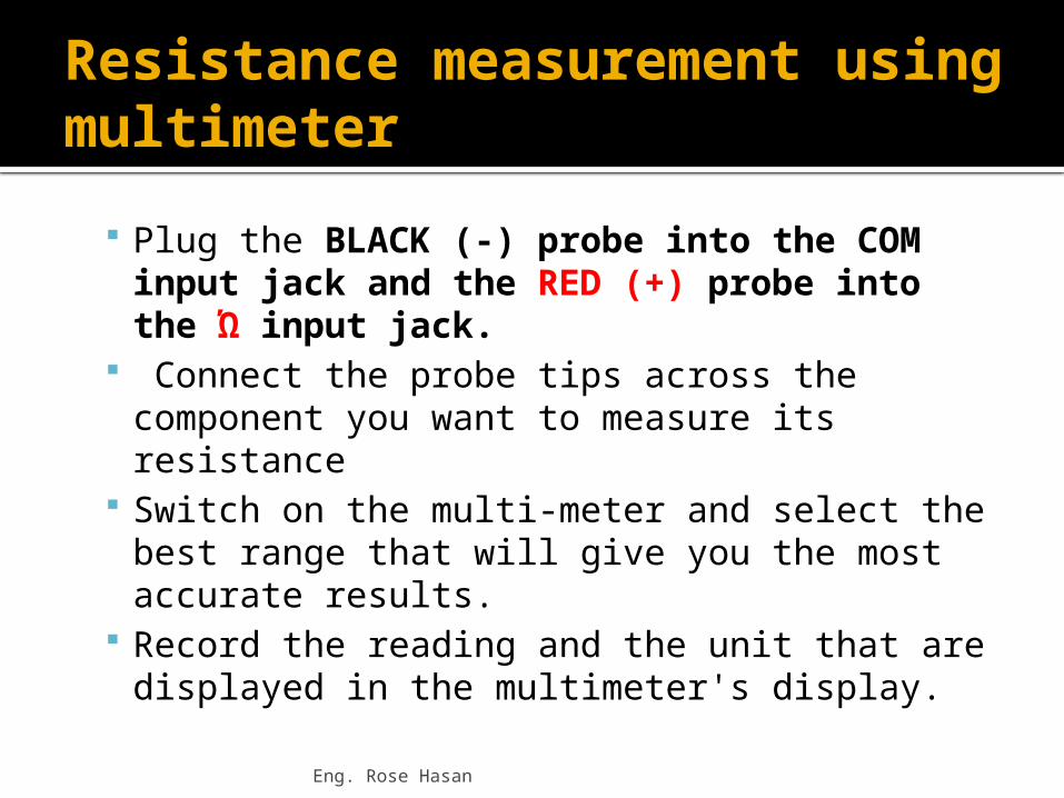
Plug the BLACK (-) probe into the COM input jack and the RED (+) probe into the Ώ input jack.
Connect the probe tips across the component you want to measure its resistance
Switch on the multi-meter and select the best range that will give you the most accurate results.
Record the reading and the unit that are displayed in the multimeter's display.
Eng. Rose Hasan

Eng. Rose Hasan

Activity 2: Resistance Measurements
Items Required:
Eng. Rose Hasan
Eng. Rose Hasan
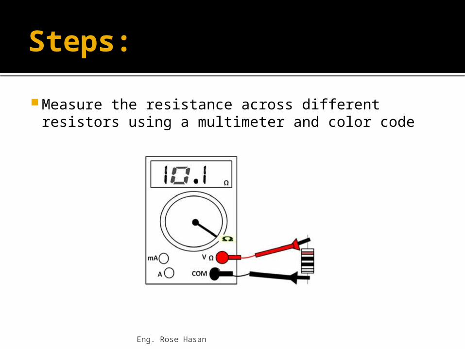
Steps: Measure the resistance across different
resistors using a multimeter and color code

Eng. Rose Hasan
Results:
2. Record your readings on the following table

Eng. Rose Hasan
Results:
3. Compare the value of resistance measured by the multi-meter and color code. Are the values close to each other?
----------------------------------------------------------------------------------------------------------------

Eng. Rose Hasan
Activity 3: Voltage and current Measurements Items Required:
Resistors (200Ώ), multi-meters Electricity & Electronics Constructor,
EEC470 Basic Electricity and Electronics Kit
EEC471-2 Power supply unit
Eng. Rose Hasan
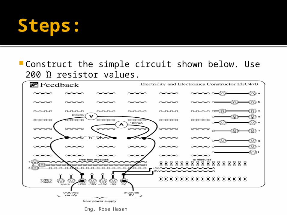
Steps: Construct the simple circuit shown below. Use 200 Ώ
resistor values.

Eng. Rose Hasan
Steps:
Connect the multi-meter to the power supply.
Make sure that the variable dc control knob is fully counter clockwise, and then switch on the power supply.
Increase the applied voltage in 2 V steps from 0 V up to 5 V.

Eng. Rose Hasan
Results:
At each step measure the current flowing in the resistor. Record your reading in the following table:
Resistance Measurements (Ohmmeter):
To measure the resistance of a resistor, follow these steps: Turn Off the power to the circuit and remove
the components to be tested. Select on the digital multi-meter's
setting switch on the lowest resistance range.
Plug the BLACK (-) probe into the COM input jack and the RED (+) probe into the Ώ input jack.
Eng. Rose Hasan

Steps:
Connect the probe tips across the component you want to measure its resistance
Switch on the multi-meter and select the best range that will give you the most accurate results.
Record the reading and the unit that are displayed in the multimeter's display.
Eng. Rose Hasan

Diode Testing: To test if the diode is functioning or not,
follow these steps: Adjust the digital Multi-meter for diode-
testing . Connect the positive lead (Red) (+) to the
anode (A(+)) and connect the negative lead (BLACK) (-) to the cathode (K(-))
Switch on the multi-meter. For a diode in a good condition the reading will be ≤ 300 mV for Ge diode and ≤ 700 mV for Si diode.
Eng. Rose Hasan

Eng. Rose Hasan
Results:

Eng. Rose Hasan
Steps & Results: Now connect the (RED) (+) lead to the
(K(-)) and (BLACK) (-) lead to the (A(+)) For a diode in a good condition the reading will
be for both types.

Continuity Test:
To test if two points are electrically connected, follow these steps: Turn Off the power to the circuit Adjust the digital Multi-meter for
continuity-testing and Switch on the multi-meter.
When the probes aren't touching, the display shows "1“.
Eng. Rose Hasan

Eng. Rose Hasan
Continuity Test:

Eng. Rose Hasan
Continuity Test: When you touch
the tips of the probes together, the display changes to a three digit mode. The multi-meter will also emit a beep.

Eng. Rose Hasan
Diode Activity
http://www.wisc-online.com/objects/ViewObject.aspx?ID=AMT2104

Eng. Rose Hasan
Function Generator
Purpose: Function generator is used to produce different waveform such as: Sine Square Triangular
Eng. Rose Hasan
Function Generator (Purpose) It is used to test and examine the
response of an electrical circuit to that signal. (i.e. the motor response to a square or
triangular signal).
Function Generator
Main Control Keys: The function generator has many control keys to control the: waveform shape amplitude Frequency
http://www.physics-chemistry-interactive-flash-animation.com/electricity_interactive.htm
Eng. Rose Hasan

Eng. Rose Hasan
The following table shows function generator main keys and their usage.
Eng. Rose Hasan
Oscilloscope
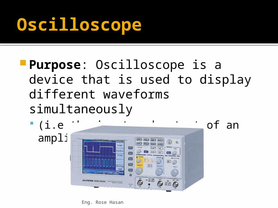
Purpose: Oscilloscope is a device that is used to display different waveforms simultaneously (i.e the input and output of an amplifier).

Eng. Rose Hasan
Main Control Keys: Oscilloscope has many control keys to scale the:
amplitude periods of the displayed waveform.

Eng. Rose Hasan
Function Generator
The following table shows some oscilloscope main keys and their usage.

Activity 4: Oscilloscope and function generators Items Required:
Function Generator Oscilloscope speaker
Eng. Rose Hasan
Eng. Rose Hasan
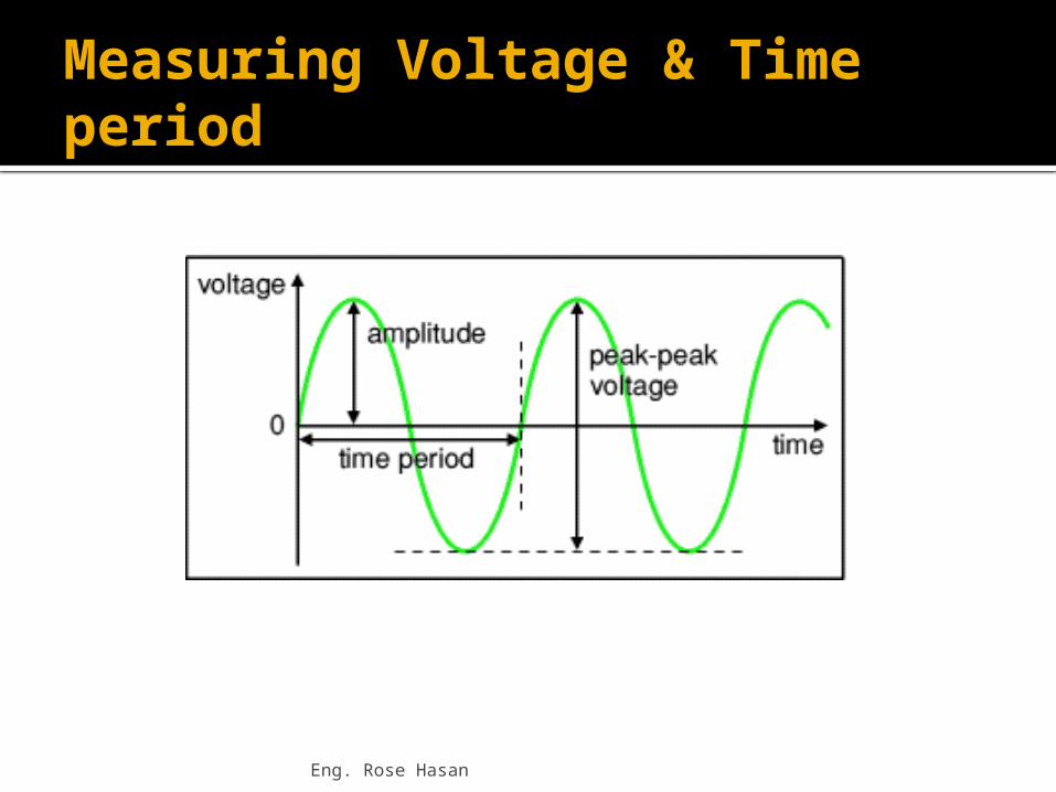
Measuring Voltage & Time period

Eng. Rose Hasan
What is the name of this testing equipment ?
Oscilloscope
Eng. Rose Hasan
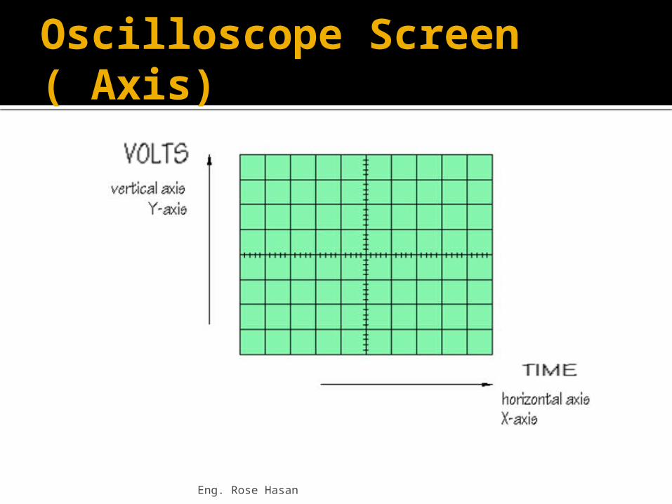
Oscilloscope Screen ( Axis)

Eng. Rose Hasan
http://physics-zone.com/lab_oscfunctiongen.html
Oscilloscope Lab Worksheet

Eng. Rose Hasan
Lab ActivitiesSteps:1. Connect the function generator and
oscilloscope as shown below.
Eng. Rose Hasan
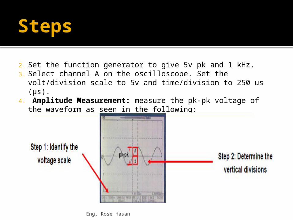
Steps2. Set the function generator to give 5v pk and 1 kHz.3. Select channel A on the oscilloscope. Set the volt/division
scale to 5v and time/division to 250 us (μs).4. Amplitude Measurement: measure the pk-pk voltage
of the waveform as seen in the following:

Cont. Steps
Volt/division scale = -----------------------------
No. of divisions = -----------------------------
Pk-Pk voltage = -----------------------------5. Period Measurements: measure
the period of the waveforms seen in figure
Eng. Rose Hasan

Eng. Rose Hasan
Cont. Steps
Time/division scale = -----------------------------
No. of divisions = -----------------------------
T (Period) = -----------------------------

Future Plan
Be prepared for a Quiz next Class in module #4.
Do Homeworks 1 & 2 (From my Wiki).
Next Class: Start with Module #5
Eng. Rose Hasan