electrical system i el - boredmder.comboredmder.com/fsms/nissan/300zx/1984/el.pdf · electrical...
TRANSCRIPT
ELECTRICAL SYSTEM I
SECTION EL CONTENTS HOW TO READ DIAGRAMS STANDARDIZED RELAY POWER SUPPLY ROUTING BATTERY. . . . . STARTING SYSTEM . STARTING SYSTEM -Starter - CHARGING SYSTEM . CHARGING SYSTEM - Alternator COMB IN AT1 ON SWITCH INSTRUMENT SWITCH HEADLAMP EXTERIOR LAMP, INTERIOR LAMP .
. .
. .
. .
. . . .
. . . . . . . . . . .
.. . . . .
. .
. . . . .
EL- 2 EL- 3 EL- 4 EL- 6 EL- 9 EL- 10 EL- 15 EL- 17 EL- 23 EL- 25 EL- 26 EL- 34 EL- 38
METER AND GAUGES - Digital Type Combination Meter . . EL- 41 METER AND GAUGES - Digital Type Combination Gauge . . . . . EL- 57 METER AND GAUGES - Needle Type Combination Meter . . . EL- 65
METER AND GAUGES - Needle Type Combination Gauge.. . . . . EL- 68 WARNING LAMPS AND CHIME. . . . . . . . . . . . . . . . . . EL- 71 VOICE WARNING SYSTEM . . . . . . EL- 76
TIME CONTROL SYSTEM . . . EL- 81 WIPER AND WASHER . . . . . . . . ... . . . . EL- 89 HORN, CIGARETTE LIGHTER, CLOCK . . . . . . . . . . . EL- 92 REAR WINDOW DEFOGGER . . . .. . . . . . . . . . . EL- 93 AUDIO AND POWER ANTENNA ,. . . . . . . . . EL- 95 AUTOMATIC SPEED CONTROL DEVICE ( A S C D ) . . . . , . EL- 97 LOCATION OF ELECTRICAL UNITS ... . . . . . . EL-104 HARNESS LAYOUT . . . . .. . . . EL-107

HOW TO READ DIAGRAMS
I POWER SUPPLY ROUTING
This diagram is helpful in identifying specific prob- lems in the power supply portion of the electrical circuits. For example, let's say a vehicle has an in- operative rear window defogger A quick check proves that meter and gauges in the vehicle are operative The power supply diagram shows that there cannot be a problem between the battery, ignition relay, ignition switch or fuse since the power supply circuit for the rear window defogger
Example
BRANCH M/T model
A lT model n
@ M/Tmodel
@ AITmodel
t ABBREVIATIONS
i s common with the meter and gauges. Therefore, the cause of this specific problem must l ie past the fuse, such as in the wiring, rear window defogger, or ground.
WIRING DIAGRAM
This diagram identifies types and number of con- nectors, electrical terminal positions in the connec- tor, color coding of wires, and connector codes Refer to the following example
CONNECTOR This shows that there connectors are white 6 terminal pin-type connectors
Pin-type connector (Male)
(Female)
(Male)
(Female)
833 Piaan-type connector
gg Piatn-type connector
POWER This shows the tgni tion w i t c h ~os i t ion ~n which the system can be operated For deiailr, refer 10
POWER SUPPLY
A r I 1 v SWITCH
., , ,-,. -..,m I This shows that conti-
u f
L-
WIRE COLOR CODING
This number IS !dentical with the one of the HARNESS LAYOUT This s h o w where the mnnenor
C a r O N I nutty exists between termmels @ and 0, when the switch 16 turned 10 ON rmition
B W R
BR =Brown = Black OR =Orange =Whi te
=Red P =Pink G =Green PU =Purple L =Blue GY =Gray Y =Yellow SB =Sky blue LG = Laghi Green
In case of color coding using a Stripe Bare Color IS given fmt. followed by the Stripe Color
Example LIW = Blue with White Stripe
EL-2

STANDARDIZED RELAY
1T
1M
2M
1M 1E
-
Outer view Circuit
I 1 0 0
Symbols Case color
BLACK
B L U E
BROWN
GRAY
d .b SEL639D
EL-3

~
POWER SUPPLY ROUTING
Wiring Diagram
FUSIBLE LINK BOX 8ATTERY
BR
- STARTING
Charging system rc- I
-Power wmdow
EL-4

POWER SUPPLY ROUTING
Fuse Fusible Link
_I
Check
SEL276
a
b
c
d
I f fuse is blown, be sure to eliminate cause of problem before installing new fuse Use fuse of specified rating. Never use fuse of more than specified rating Do not install fuse in oblique direction, always insert it into fuse holder properly Remove fuse for clock if vehicle is not used for a long period of time.
A melted fusible link can be detected either by visual inspection or by feeling with finger tip If i t s condition is questionable, use circuit tester or test lamp
CAUTION a If fusible link should melt, it i s possible that
critical circuit (power supply or large current carrying circuit) i s shorted In such a case, care- fully check and eliminate cause of problem Never wrap periphery of fusible link with vinyl tape Extreme care should be taken with this link to ensure that it does not come into con- tact with any other wiring harness or vinyl or rubber parts
b
EL-5

BATTERY
CHECKING SPECIFIC GRAVITY
1 Read hydrometer and thermal gauge indica- tions as eye level.
Read top level with scale.
CAUTION: a. If it becomes necessary to start the engine with a booster battery and jumper cables, use a
12-volt booster battery b. After connecting battery cables, ensure that they are tightly clamped to battery terminals for good
contact c. Never add distilled water through the hole used to check specific gravity.
2. Convert into specific gravity a t 20°C (68°F) Example e When electrolyte temperature is 35°C (95°F)
and specific gravity of electolyte is 1230, converted specific gravity a t 20°C (68°F) is
Check
- Hydrometer 1 240 When electrolyte temperature is 0°C (32°F) and specific gravity of electrolyte is 1.210, converted specific gravity at 20°C (68°F) is
1.196.
Converted specific gravity (S, 1
1
1 , I I I I I 1 - I -30 -20 -10 0 10 20 30 40 50 1-221 1-41 1141 132) 1501 1681 (86) (104) (1221
SELCdZD Electrol) te temperature "C ('F)
EL-6

BATTERY
Full charging specific gravity at 20°C (68°F)
Check (Cont’d)
Converted specific gravity at 20°C (68°F)
1 26 I 120
I Recharging necessary I
BATTERY CAPACITY TEST
1 With battery connected to tester as shown, turn load knob until a draw of 3 times the battery rating is shown (Example Battery rating 60AH Turn load to 180A draw ) Hold this draw for 15 seconds, then look a t voltage I f voltage remains at 96 volts or above, THE BATTERY IS GOOD I f voltage drops below 9 6 volts, then proceed to next test
2
THREE-MINUTE CHARGE TEST 1 Connect battery charger 2 3
Turn charger to a fast rate not over 40A After three minutes, check voltmeter reading If it is over 16 5 volts battery should be re- placed
EL-7

BATTERY
CHARGING RATE AND SPECIFIC GRAVITY OF BATTERY ELECTROLYTE
The relationship between the charged condition of the battery and the specific gravity o f battery electrolyte differs, as shown in figures below, when the battery is discharging and when it IS
being charged
Charging battery a t a curreni 1/10 battery capacity
100 80 60 40 20 0 Charged rare (I" %J
SEL8088
Chargtng battery a t a curreni 116 of battery capacity
100 80 60 40 20 0
Charged rate (In %) SEL809B
As can be seen from these figures, the battery has the following features
The specific gravity of battery electrolyte increases very slowly while the battery is being charged The smaller the charging current, the slower the specific gravity of the electrolyte increases
ling
WARNING: a. Keep battery away from open flame while
it is being charged b When connecting charger, connect leads
first, then turn on charger. Do not turn on charger first, as this may cause a spark.
c. Do not allow electrolyte temperature to go over45"C (113°F).
CHARGING CURRENT AND TIME REQUIRED FOR CHARGING
Charge the battery a t 1/10 the current of battery capacity
Charging current I Time required
1/10 of battery capacity I Approx 8 - 10 hours
116 of battery capacity (But not more than 10-ampere) Approx 4 - 5 hours
~~ ~
CAUTION: Do not use more than 10-ampere current f low t o charge the battery quickly, as this will shorten the battery's service life.
-Service Data and Specifications -
Applied model Canada .
Ma,ntenance-free
Capacity V-AH I 1 x 0 j 12-70
1 126 I 1 2 8 Full charging specific grav i~y
at 2O'C 168°F)
EL-8
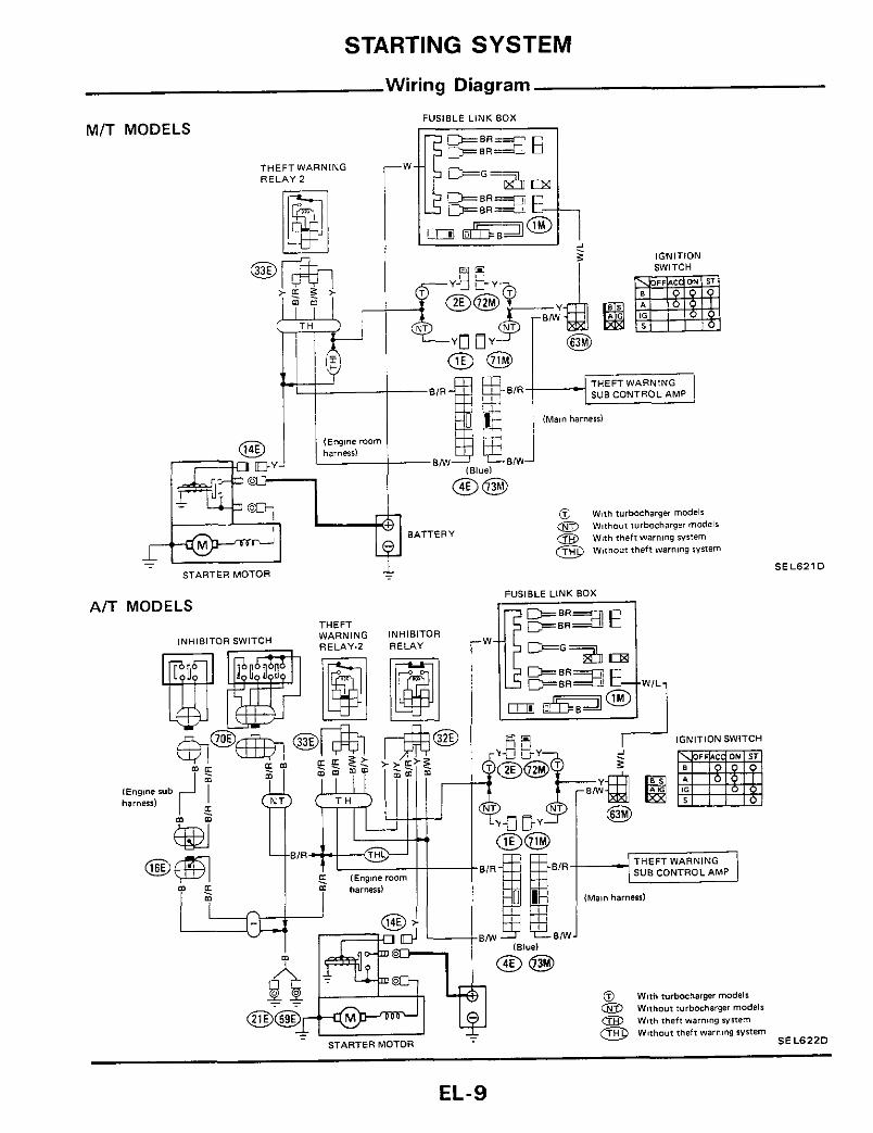
STARTING SYSTEM
Wiring Diagram
MIT MODELS FUSIBLE LINK BOX
THEFT WARNING RELAY 2
IGNITION SWITCH
-1 -
STARTER MOTOR
AIT MODELS
lNHlBlTOR SWITCH
BATTERY
THEFT WARNING R E L A Y 9
INHIBITOR RELAY .W
FUSIBLE LINK BOX
E L - 9

STARTING SYSTEM -Starter-
Construction
S114-3748
SEL623D
EL-I 0

~~
STARTING SYSTEM -Starter-
Magnetic Switch Check
1 Continuity test (between "S" terminal and switch body)
No continuity Replace
From battery
VL Ohmrnet
2 Continuity t e s t (between "S" terminal and "M" terminal)
No continuity Replace
Coli
SEL047D
- Pinion/Clutch Check
1 Check clutch Check pinion to see that it locks properly when turned in "drive" direction and rotates smoothly when turned in reverse
SEL569B
Pinion does not lock in either direction or unusual resistance is evident Replace
Replace pinion if teeth are worn or dam- aged (Also check condition of ring gear teeth )
Replace clutch gear if teeth are worn or damaged (Also check condition of arma- ture shaft gear teeth )
2 Inspect pinion teeth.
3 Inspect clutch gear teeth
EL- I 1
STARTING SYSTEM -Starter-
Brush Check
BRUSH
Check wear of brush
Wear limit length: 11 mm (0.43 in)
Vernier caliper
SEL626B
Excessive wear Replace
BRUSH HOLDER
1 Perform insulation test between brush holder (positive side) and i t s base (negative side)
SE L568B
Continuity exists . Replace
smoothly 2 Check brush holder to see i f it moves
I f brush holder i s bent, replace it, if sliding surface is dirty, clean
Field Coil Check
Continuity test (between field coil positive terminal and positive brushes)
ositive terminal
‘Ohmmeter
No continuity Replace fielk ~
SELUq6A
:oil Insulation test (between field coil positive terminal and yoke)
Postwe terminal I
1 %
Continuity exists Replace field coil
EL-I 2

STARTING SYSTEM -Starter-
1 Continuity test (between two segments side by side)
I Y Ohrnketer
a No continuity Replace Insulation test (between each commutator bar and shaft)
2
EE022
a Continuity exists Replace
a Rough . Sand lightly with No 500 - 600 3 Check commutator surface
sandpaper
! Check
4 Check diameter of commutator
Commutator minimum diameter
Less than specified value Replace
29 mm (1 14 in)
vernier caliper
tJ \Cornmurator
SEL418A
5 Check depth of insulating mica from commuta- tor surface a Less than 0 2 mm (0 008 in) Undercut
to 0 5 . 0 8 mrn (0 020 - 0 031 in) Undercut procedures
Round 0 5 - 0 8 m m (0 020 0 031 in)
Correct
Commutator
incorrect E E O Z I
EL-1 3
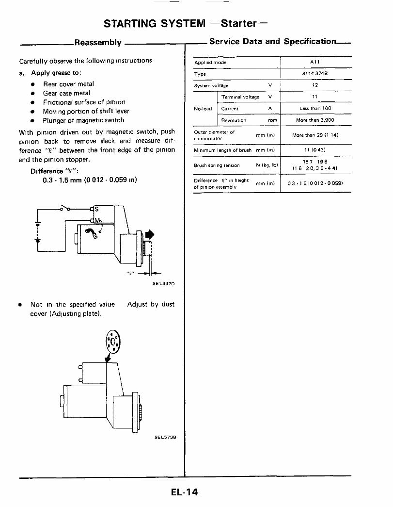
STARTING SYSTEM -Starter-
Minimum length of brush mm (In)
Reassembly
11 10431
Carefully observe the following instructions
a. Apply grease to:
Rear cover metal Gear case metal Frictional surface of pinion
Plunger of magnetic switch Moving portion of shift lever
With pinion driven out by magnetic switch, push pinion back to remove slack and measure dif- ference "2" between the front edge of the pinion and the pinion stopper.
Difference "P": 0.3 - 1.5 mm (0 012. 0.059 in)
"Q" 4+ SEL497D
Not in the specified value Adjust by dust cover (Adjusting plate).
SEL5738
- Service Data and Specification-
- Applied model I A1 1
Less than 100 - I Revolution rpm I Mare than 3.900
I More than 29 (1 141 Outer diameter of commutator
mm (in1
157 1 9 6 1 116 2 0 . 3 5 - 4 4 ) Brush spring tension N (kg. Ibl
mm(in1 1 0 3 - 1 5 1 0 0 1 2 - 0 0 5 9 1 Difference P" in height of pinion assembly
EL-I 4
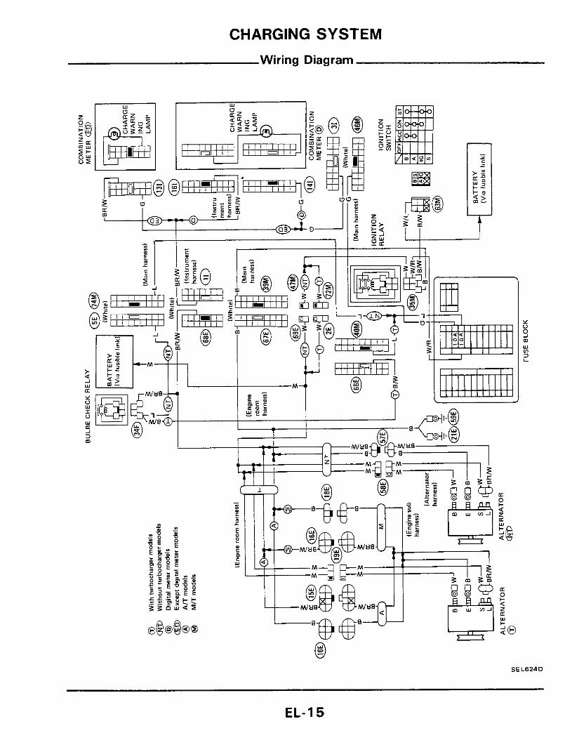
CHARGING SYSTEM
Wiring Diagram
SEL6240
EL - I 5

CHARGING SYSTEM
Make sure "S ' termmal 8s con- IC-RG IC regulator
When reaching "Damaged A C G.", remove 0 K. IC-alternator 16 In good condltlon nected COrreCtly
Trouble-Shooting
Before conducting an alternator test, make sure that the battery IS fully charged A 30-Volt voltmeter and suitable test probes are necessary for the test The alternator can be checked easily by referrmg to the Inspection Table
Engine tdltng Lighting $witch "ON,, (Check light for operatlonl
WITH IC REGULATOR
bulb Replace and Proceed -
Wpth alternator side L terminal grounded, internal short occurs when + diode IS short-circuited @
Ignition witch "ON" cOnneCtor IS. (Check light Ll and ground for operatton1 L lead w ~ r e Connect con-
I lH,TACHl nector IS LI far operation1 and ground F
I [Check Itght I for operation1 I (MITSUBISHI ' makel I - - - - - - - - - - - - -------- -
J
. . . . . . . . . . . . . . . . . . . . . . . . . . Contact poiitwe lead (+ I of voltmeter on B
Lqht "OFF" 9 Engine speed 1,500 rpm
terminal and negative lead (-1 to L terminal
(Measure the "oltage acres "E" and "L"
only) Contact tip of wlre with brush and attach wire to alternator body
-0 Light"0FF" -- O K
5 ) Terminals "S", "L", "BAT" and "E" are marked on rear cover of alternator.
Brush lift wire
SEL766D
EL-1 6

CHARGING SYSTEM -Alternator- Construction
A2T48195 (MITSUBISHI make) Through-bolt m 3 9 541040-055.29 401 ,- Front cover r
I
- ~ e a r ~ n g retainer
- Diode assembly 16 0 . 7 5,43 54)
("1 N m lkg-rn. it-lbl
SEL625D
*Rear bearing CAUTION. Rear cover may be hard to remove because a ring is used to lock outer race of rear bearing Be careful not to lose this ring during removal.
LR170-701B (HITACHI make)
(4 0 -6.0, 29.43) n 39 59
("1 N m Ikg-m, ft-lbl
Dlodt, assembly SEL626D
EL- I 7

____ ____
CHARGING SYSTEM -Alternator-
Removal
Remove bolts from alternator Remove bolts for front stabilizer Manually move stabilizer down and remove alternator
SEL627D
Disassembly
CAUTION. Rear cover may be hard to remove because a ring IS used t o lock outer race of rear bearing To facili- tate removal of rear cover, heat just bearing box section with a 200-wan soldering iron Do not use a heat gun, as it can damage diode assembly.
SEL628D
Rotor Slip Ring Check
1. Continuity test Ohmmeter
SEL629D
No continuity Replace rotor 2. Insulator test
Ohmmeter
IWI
SEL630D
Continuity exists. Replace rotor. 3. Check slip ring for wear.
Slip ring minimum outer diameter. 21.6 mm (0.850 in) [HITACHI makel 22.4 mm (0.882 in) [MITSUBISHI makel
EL- I 8

CHARGING SYSTEM -Alternator-
Brush Check
1 Check smooth movement of brush Not smooth Check brush holder and clean
2 Check brush for wear
SEL631D
Replace brush if it is worn down to the
3. Check brush pig tai l for damage Damaged Replace
4 Check brush spring pressure Measure brush spring pressure with brush pro- jected approximately 2 mm (008 in) from brush holder
Spring pressure.
limit line
1.471 - 3.531 N (150 - 360 9, 5.29 - 12.70 02) [HITACHI make]
10.93 - 15 17 0 2 ) [MITSUBISHI make] 3.040 - 4 217 N (310 - 430 9,
2 mm (0 08 in1
I P -
EE049
Not in the specified value Replace
- Stator Check
To test the stator or diode, you must separate them by unsoldering the connecting wires.
CAUTION. Used only as much heat as required to melt solder. Diodes will be damaged by excessive heat.
Long nose pliers used a$ a heal sink -1, /
\
SEL054D
1 Continuity test
y _ Lead wire - SEL070
No continuity Replace stator 2 Ground test
SE LO7 1
Continuity exists Replace stator
EL-19
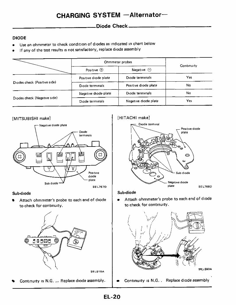
CHARGING SYSTEM -Alternator-
Ohmmeter probes
~ositive 0 Negative 8 Positive diode plate Diode terminals
Diode terminals Positive diode plate
Negative diode plate Diode terminals
Diode terminals Negative diode plate
Diodes check (Positive side)
Diodes check (Negative side)
Diode Check
Continuity
Yes
No
No
Yes
[ MlTSUBlSHl makel Negatwe diode plate
\
piate
S E L 7 6 7 D Sub dlode
Subdiode
Attach ohmmeter's probe to each end of diode to check for continuity.
S E L 9 1 0 A
Continuity is N.G. ... Replace diode assembly.
[HITACHI makel
S E L 7 6 8 D
Subdiode
Attach ohmmeter's probe to each end of diode to check for continulty.
Continuity is N.G. . Replace diode assembly
EL-20
CHARGING SYSTEM -Alternator-
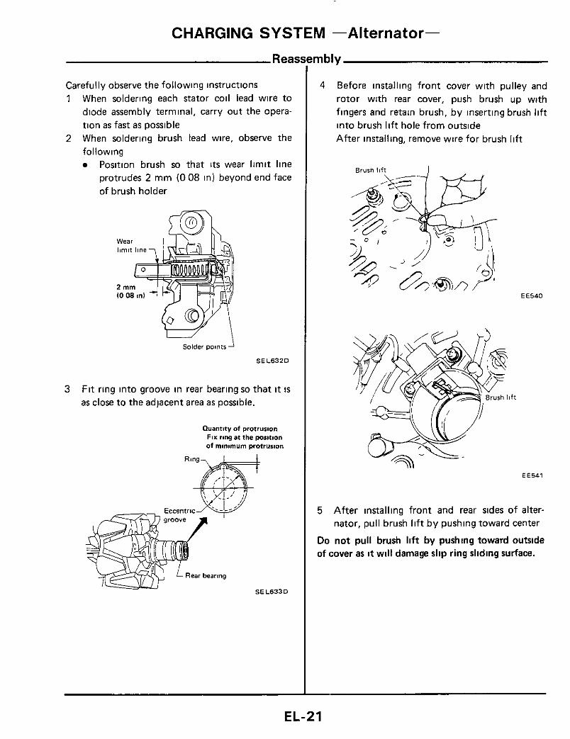
Reasi
Carefully observe the following instructions 1 When soldering each stator coil lead wire to
diode assembly terminal, carry out the opera- tion as fast as possible
2 When soldering brush lead wire, observe the following
Position brush so that i t s wear limit line protrudes 2 mm (0 08 in) beyond end face of brush holder
Solder points
S E L 6 3 2 0
3 Fit ring into groove in rear bearing so that it is as close to the adjacent area as possible.
Quantity of prorrusion FIX ring at the position of minimum protrusion
mbly
4 Before installing front cover with pulley and rotor with rear cover, push brush up with fingers and retain brush, by inserting brush lift into brush lift hole from outside After installing, remove wire for brush lift
EE540
EE541
5 After installing front and rear sides of alter- nator, pull brush lift b y pushing toward center
Do not pull brush lift by pushing toward outside of cover as it will damage slip ring sliding surface.
EL-21

CHARGING SYSTEM -Alternator-
Service Data and Specification
LR170-701B
Applied model
A2T48195
Nominal rating V-A
Ground wlarity
Minimum revolution undt no-load (when 14 volts IS
applied) rpm
Hot output current Alrpm
Regulated output voltage V
Minimum length of brush rnm (m)
Brush spring pressure N 1% 0 2 )
Slip ring outer diameter mm Ion)
W8thout turbo With turbocharger charaer models models
12-70
Negative
Less than 1.000
More than 2111,300
More than 5012,500
More than 7015,000
1 4 4 - 1 5 0
More than 55102171
1,471 - 3,531 1150-360.
5 29 - 12 701
More than 21 6 I O 850)
Less than 1,100
More than 21 11,300
More than 5012,500
1 4 1 1 4 7
More than 8 10311
3,040 4,217 I310 - 430,
1 0 9 3 - 15 17)
More than 22 4 10 8821
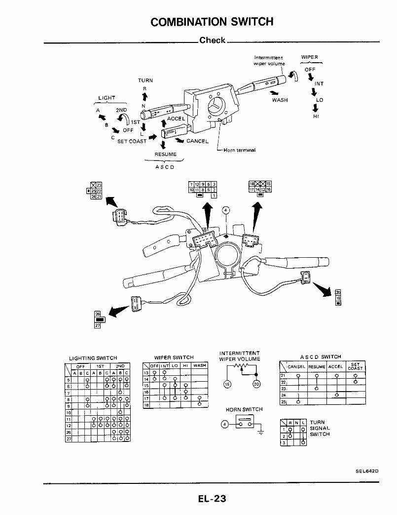
COMBINATION SWITCH
Intermittem WIPER wimrvolume
WASH
TURN
Horn terminal RESUME
OFF
INT s L 4 LO
HI
A S C D
LIGHTING SWITCH WIPER SWITCH INTERMITTENT WIPER VOLUME A S C D SWITCH
HORN SWITCH
TURN SIGNAL SWITCH -
SEL64ZD
EL-23

COMBINATION SWITCH Replacement
Lighting switch, wiper & washer switch and A S C D switch can be replaced without removing combination switch base
Swtch base
Lighting switch
Washer swmh
A S C D sei switch SEL643D
To remove combination switch base, remove base attaching screw and turn after pushing on it
Attaching screw
Protrusion gu!dei
Hole
SEL644D
EL-24

INSTRUMENT SWITCH
p7J-q
INSTRUMENT
RETRACT SWITCH
HAZARD SWITCH
E:EGGER SWITCH
OFF
[WJ]
-'+ Dark N
(For A S C D switch)
(Far illuminafion control swifchl
HAZARD RETRACT SWITCH SWITCH
A S C D MAIN SWITCH
I LLUMlNATlON CONTROL SWITCH
BRIGHT DARK El
INSTRUMENT SWITCH R.H. m
REAR WIPER &WASHER SWITCH
RE4R DEFOGGER SWITCH
REAR WIPER &WASHER SWITCH
AUXILIARY DRIVING LAMP SWITCH
For removal, refer to "INSTRUMENT" in BF section
EL-25

HEADLAMP
Operation
0 The following chart depicts the operational modes of relays and headlamp motors in relation to the posi- nons of the headlamD and retract switches
Light switch
Retract switch
Mal”
Dimmer Headlamp
Uphold relay
Headlamp relay
Pasrlng relay
Headlamp mofor
Parsing -2ND 7
Main n n 1 ST
I I I I I I I I , I , , 1 I 1
I , I I OFF 1 1 I I
I I 1 I I OFF I I 1 I
I I I I
I I I I I
UP
I I 1 1 1
I I l l
I I I ! I j ON
I I
I ON
I I I I
I
OFF I
I I I I
I 1 I I 1 1 I 1
I / OFF
I I 1 , I ! I I OFF
~
I I UP DOWN
SEL743D
EL-26
- BATTERY T I R F I A V 1 7
THEFT WARNING
r --, I I I
I
"$ 7; ' / ' '
PASSING RELAY
k=a-J \-UPHOLD RELAY I 1V.
@ Wnihoul headlamp warning
0 Wnh headlamp warning
HEADLAMP
Wiring Diagram
HEADLAMP MOTOR R H
R H
HEADLAMP
HEADLAMP MOTOR L H
HEADLAMP
RELAY I t T type Black)
EL-28

L
,
sin Mld u f
HEADLAMP Trouble-shooting
Check diodes between light switch and up hold relay
1 O K
Check harness between headlamp relay and headlamp motor
headlamp motor When turning retract switch to "UP", do headlamps open?
Check headlamp Yes relay
Check headlamp motor
Turn retract switch to "DOWN"
between headlamp relay and headlamp motor
v
When turning light r switch to "ZND", do
-No When turning light switch to "OFF". do headlamps close?
~
on, I headlampsopen? I I
Replace headlamp timer
-. - I
(es
switch
Check up hold relay 1 I
lo Check diodes between light switch and up hold relay
O K
between light switch and headlamp motor
When turning light switch to "PASSING", Replace headlamp do headlamps open?
Headlamps do not close F (Turn light switch to "OFF" \
c - No
When turning retract switch to "DOWN", do headlamps close?
I - Check headlamp relay
Yes
Check retract switch
Check headlamp
EL-30
LE-13
\ \

HEADLAMP
Installation
1 Set the headlamp motor to "DOWN" position Connect harness to headlamp motor and set retract switch to "DOWN" Headlamp motor can now be set to "DOWN" with retract switch Install the headlamp link assembly and head- lamp motor in the body
When installing the link to the motor, make sure the motor link is installed as shown below
2
3 Install the connecting link
,Aligning mark fordown
Motor
SEL649D
Adjustment
After installing connecting link, always adjust it as follows
1) Set the headlamp to "DOWN" positlon 2) Adjust connecting link so that the lid IS proper-
ly aligned with hood and fender
3) Set the headlamp to "UP" position 4) Adjust stopper screw
SEL65'D
EL-32
HEADLAMP
0 0
Headlamp Motor Check
0 No
8 Yes
Use an ohmmeter to check for continuity in headlamp motor circuit while rotating motor with manual knob
CAUTION. Prior to performing continuity test, disconnect ground cable from battery.
Ohmmeter probe Headlamp Continuity
Yes
No
Alqning mark for
for up posltlon
SEL652D
- Aiming Adjustment
When performing headlamp aiming adjustment, use a i l aiming machine, aiming wall screen or headlamp tester For operating instructions of any airner, it should be in good repair, calibrated and used ac- cording to respective operation manuals supplied with the unit If any aimer i s not available, aiming adjustment can be done as follows
For details, refer to the regulations in your own country.
CAUTION: a Keep al l tires inflated to correct pressures. b. Place vehicle and tester on one and same f la t
surface. c See that there i s no load in vehicle (coolant, en-
gine oil filled up to correct level and full fuel tank) other than the driver (or equivalent weight placed in driver's position).
W ~ = l , l t O ( 4 4 0 9 I c 'L
- 7
, - LO 1300 001
Of headlamps
UPper edge of Vertical centerline ahead of headlamps -x high tntenrw zone
Height of lamp centers I . -
100 141 100 (41 .-
L A
4 . . I . .
100 1100 1001 loo (41 (41 \ / (41 (41
K L e f t edge of high intensity zone
= ACCEPTABLE RANGE untt mm (in1
SEL914D
Adjust headlamps so tha t upper edge and left edge of high intensty zone are within the ac- ceptable range as shown in the figure above Dotted lines in illustration show center of headlamp.
EL-33
FUSE BLOCK
r BATTERY Ll-J
I I
BODY GROUND
SIDE MARKER IR H ridel LAMP R H
BODYGROUND
FRONT COMBINATION L/Y- LAMP R H L/OR -
@ STOP LAMP SWITCH
CLEARANCE
BODY GROUND
CLEARANCE
BODY GROUND (L H ridel
CLEARANCE
(Engine room harness1
I W h m
-R/G-
FRONT COMBINATION LAMP L H
b VI w 0
SIDE MARKER LAMP L H
T A I L A N 0 STOP LAMPSENSOR
0 SFmodelr
@ GLrnodelr
@ GLLrnodelr
@ Digital type meter
@ Needle type meter
L H ride1
m m
BODYGROUND (L H ridel
LICENSE LAMP
REAR COMBINATION LAMP L H
STOP TAIL
R /G
REAR SIDE MARKER LAMP L H

EXTERIOR LAMP
Auxiliary Driving Lamp/Wiring Diagram
Back-up Lamp/Wiring Diagram
BODYGROUND (R H $idel
1 FUSEBLOCK - REAR COMBINATION LAMP R H
IMsin hsmenl
IWh8te R H ridel
lEng8nc rubharnenl @ Non WrMcharger models @ BODY GROUND q C L H sidel - INHIBITOR
WITCH SEL655D
EL-35
rn r i, m
BODY GROUND
@ FRONT COMBINATION LAMP R H
B- EMF G/R-
R H @
FRONT COMBINATION LAMP L H
1 s
L H @
@
BODY GROUND
@ Digital tvPe carnb6nation meter equnpped model
@ Needle type m combmation meter
equlpped model rn r 0 In 01 0
BODYGROUND -
I I I I I 1 I I I J
E% TURN L H
-0 I
REAR COMBINATION @@ LAMP L H
IGNITION SWITCH ON or START

EXTERIOR LAMP
- Item
- Headlamp
Au, iliary driving lamp
Front combination lamp
Front side marker lamp
Rear side marker lamp
Rear cornbination lamp 1-urn signal StopITail Elack-up
Lictme plate lamp
Interior lamp
Spot lamp
Rear (luggage) compartment lamp
Door step lamp
Leg room lamp -
-Stop and Tail Lamp Sensor Check,
0 Before c h e c k i n g , ensure that bulbs meet Wattage (W)
65,35
55
2718
3 4
3 4
2718 2718 27
4 0
10
a
3 4
5
2
s o e c i f i c a t i o n s
STOP LAMP
Stop lamp s w i t c h on
Stop lamp on good order
stop lamp removed Approx 12 volts
Approx 2volt6
voltmeter
SEL170B
TAIL LAMP
L i g h t i n g s w i t c h on
Tad lamp mgood order
Tail lamp removed ~ p p r o x . 12 vans
. Approx 2 volts
SEL1710
- Bulb Specifications
SAE trade number
Hi3054 -
1157
158
158
1157 1157 1073 -
-
-
-
- -
EL-37

III
I - I -
ILLUMINATION ILLUMINATION lllluminai~on CONTROL controt SWITCH switch1
n ILLUMINATION
COMBINATION METER
INSTRUMENTSWITCH L H m r 0) ul 4 0
COMBINATION INSTRUMENT COMEINATION COMBINATION METER SWITCH R H GAUGE GAUGE
FUSE BLOCK
I BATTERY I TIME CONTROL UNIT [Refer to "TIME
CONTROL SYSTEM I I
LIR
@ SF models
IWhiIel DOOR STEP @ GLmodelr (Door harness R H I LAMP R H @ GLLmodelr
@ D8g1tal t v ~ e meter
@) Needle type meter
J ~ / ~ U LIR U
I 1 I I I
. BODY GROUND IL H ridel

rn I-
0 &
TIME CONTROL UNIT (Refer to 'T IME CONTROLSYSTEM" h
@$ STEP LAMP R H @=@L/R L / E
INTERIOR
@ :;: STEP
LAMP L H
@) Digital type meter
@ Needle type meter
J
I i DOOR HANDLE SWITCH
IDoor harness L H )
L/R
G/R KEY HOLE ILLUMINATION

METER AND GAUGES - Digital Type Combination Meter
combination Meter
CAUTION: No electrical terminal should be touched wlth bare hands.
EL-41
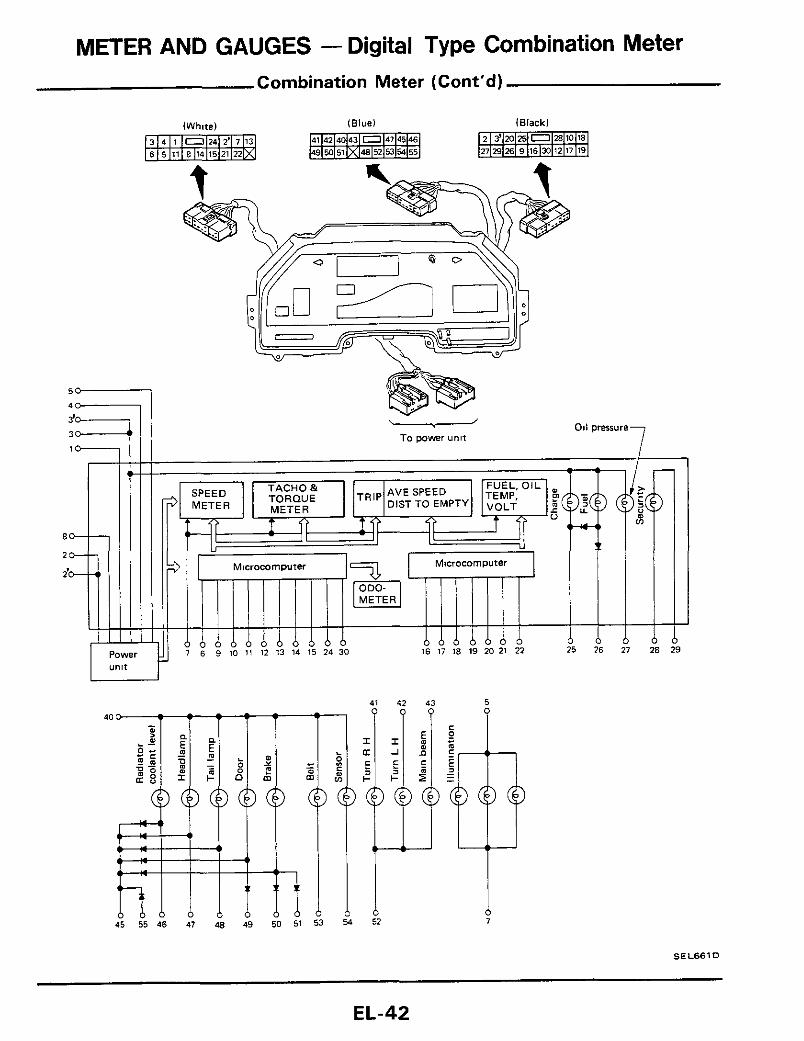
METER AND GAUGES - Digital Type Combination Meter Combination Meter (Cont'd)
--
Power ""lt
To power uni t
12 13 14 15 24 30 16 17 18 19 20 21 22 6 21 28
40
45 55 46 47 48 49 50 51 53 54
;I4 E
i
SE L661 D
EL-42

FUEL TANK GAUGE (Main1
'I
SI
0 1
7 4 I - 0 I
A FUSE
__Izt___l

METER AND GAUGES - Digital Type Combination Meter Wiring Diagram
EL-44

METER AND GAUGES - Digital Type Combination Meter Wiring Diagram (Cont'd)
GY LIR
tiT POWER
TACH0 & TORDUE METER
SPEED METER
SEL663D
EL-45
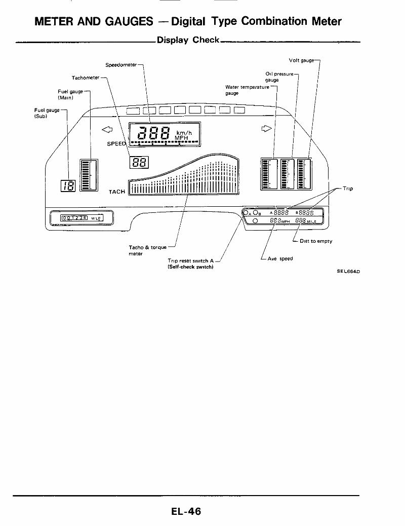
METER AND GAUGES - Digital Type Combination Meter Display Check
EL-46

METER AND GAUGES - Digital Type Combination Meter
- (+) (-) OFF
Display Check (Cont'd)
a Digital combination meter is provided with a self-check function to determine whether or not meter itself is malfunctioning.
Test procedure
(1) While pushing trip reset switch A, switch igni- tion switch from "OFF" to "ON" Trip reset switch A should remain pushed in until self- check operation start
(2) Meter starts to automatically perform self- check. Segments for meters and gauges should illuminate one after another.
(3) If any particular segment remains off, corn- bination meter itself is faulty.
ACC ON -Preparation for Trouble-shooting -
0 \
Approx 12v
0 ov ov
SEL665D
a Remove instrument switch
a Remove cluster lid A
Remove nut which holds instrument switch
- Trouble-shooting
I Go to "Display check" I 1 N G
power source circuit unit
-IF' L - I F - N G
Replace meter and gauge assembly
Check for loose harness connector
Voltmeter terminals Ignition switch position
Ohmmeter terminals Ignition Switch OFF
Continuity exists ground
a Disconnect meter harness connector as shown below
.
SEL744D
- EL-47

METER AND GAUGES - Digital Type Combination Meter Trouble-shooting (Cont'd)
Replace meter and gauge assembly
Speedometer does not operate
Go to "Display Check"
Check harness between speed sensor and meter
O K Go to "Power Unit Check"
T T Replace meter Replace and gauge assembly power Unit
Go t o "Speed Sensor Signal Check" to check speed sensor output
Go to "Display Check"
Go to "Power Unit Check"
O K
Replace meter Replace and gauge assembly power unit . 1 Check ignition coil circuit I
and gauge assen 1' T l N G
Replace meter Check resistor, ignition and gauge assembly coil and power transistor
(Refer t o ignition system)
1 Disconnect meter harness connector
2 3 Check terminal voltage between @ and
(white) Turn ignition switch to "ON".
0
VOltmeter SEL6660
EL-48

METER AND GAUGES - Digital Type Combination Meter Trouble-st
Torque meter does not operate
1 Go to "Display Check" I
Go to "Power Unit Check"
v Replace meter Replace and gauge assembly power unit
I
I Check boost sensor circuit I
boost sensor and meter boost sensor
1 Disconnect meter harness connector
2 Connect vacuum pump gauge to boost
3 4
(white)
sensor vacuum hose Turn the ignition switch to "ON" Apply vacuum pressure to boost sensor by vacuum pump gauge and measure voltage across 0 and
Vacuum -
~ e e p harness connected
J wu 1 3v at-53 3kPa 1-400 mmH
SEL667 Voltmeter -15 75 mHg) '
rg (Cont'd)
Main fuel gauge does not operate
I
Go to "Display Check"
Go to "Power Unit Check"
Replace meter Replace and gauge power unit assembly
Check fuel tank main gauge clrcult
I O K
Replace meter and gauge assembly
Go t o "Fuel tank gauge check"
. Check harness between Replace fuel fuel tank gauge and meter tank gauge unit
1 Disconnect meter harness Connector (black) Turn ignition switch t o "OFF" 2
3 Measure resistance between @ and @
e
\
Ohmmeter SEL6680
EL-49

METER AND GAUGES - Digital Type Combination Meter Trouble-shooting (Cont'd)
Fuel residue
Sub fuel gauge (digital display1 does not operate
Go to "Display Check"
Go to "Power Unit Check"
Replace meter Replace and gauge power unit assembly
Resistance
Check harness
Check fuel tank sub gauge circuit
Go to "Fuel Tank Gauge Check"
O K
v T
Replace Check harness between Replace meter fuel tank fuel tank gauge and meter and gauge gauge unit assembly
FUEL INJECTION PULSE CIRCUIT CHECK
1 Disconnect meter harness connector (black)
2. Turn ignition switch to "ON" 3 Check for voltage across @$ and 0.
Voimeter SE L669 t
FUEL TANK SUB GAUGE CIRCUIT CHECK
1 Turn ignition switch to "OFF" 2. Measure resistance between 0 and 0.
Ohmmeter
Ignition switch- OFF
More than ZOQ Less than 4R S E L 6 7 0 D
EL-50

METER AND GAUGES - Digital Type Combination Meter Trou ble-sho
Go to "Display Check"
O K
Go to "Power Unit Check"
T
Replace meter and gauge assembly
Replace power unit
T Replace meter and gauge assembly
ng (Cont'd)
Only water temp gauge does not operate
I
Go to "Display Check" T
O K
Replace meter and gauge assembly
Check water temp sensor (thermistor) Circuit
O K N G
Replace meter and gauge assembly
Check harness between Replace thermistor and meter thermistor
1 Disconnect meter harness connector
2 3
(black) Turn ign i t ion swltch to "OFF" Measure resistance between 0 and @
!'W I 1 Ohmmeter
ignition switch - OFF
Resistance
70CI or more
6O'C or more Approx 10 - 70R
SEL6710
EL-51
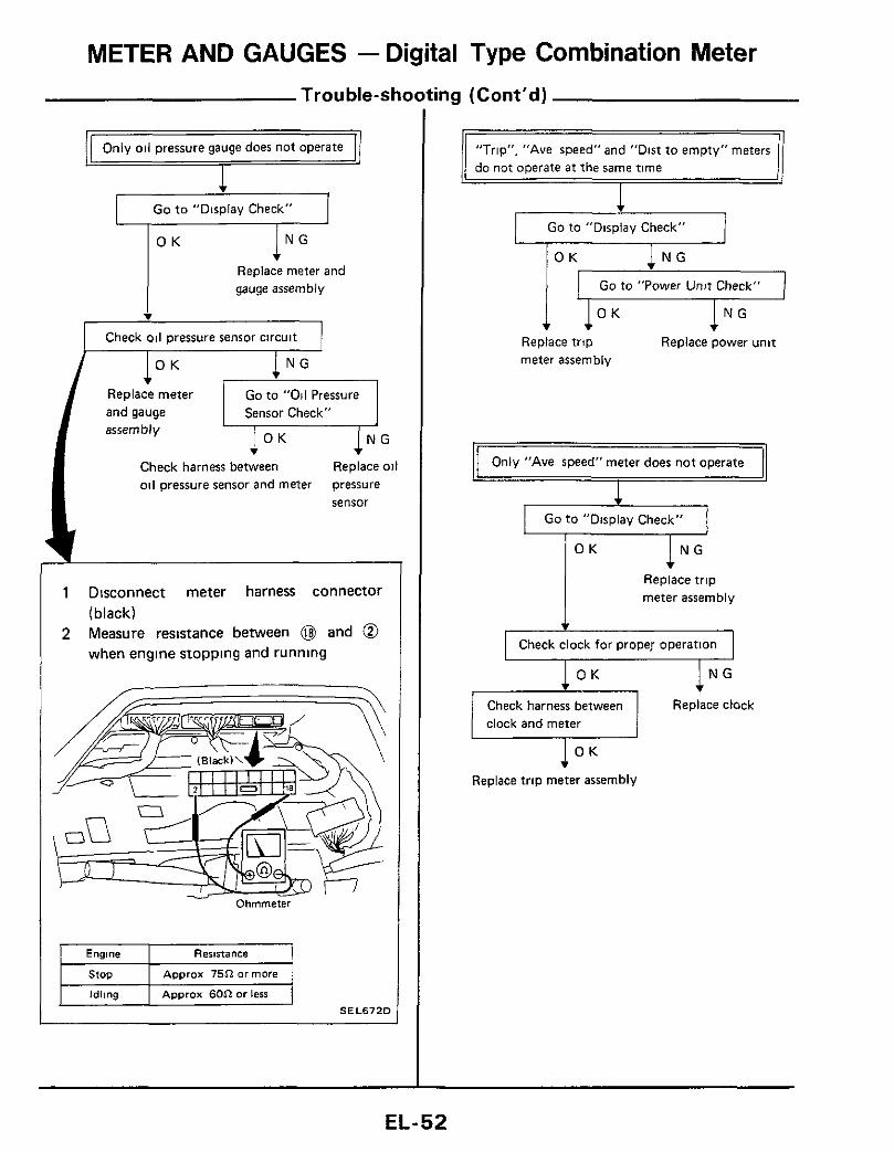
METER AND GAUGES - Digital Type Combination Meter Trouble-shooting (Cont’d)
Go t o “Displav Check”
I N G O K
Replace meter and gauge assembly
v
Check oil pressure sensor circuit
O K N G
Go to “Oil Pressure Sensor Check”
Replace meter and gauge assembly
Check harness between Replace oil oil pressure sensor and meter pressure
sensor
1 Disconnect meter harness connector (black)
2 Measure resistance between @ and @ when engine stopping and running
Ohmmeter
Engine Resistance
Approx 75R or more
Idling Approx 60R or less
SEL672D
“Trip”, ”Ave speed” and “Dist to empty” meters
1 Go to ”Display Check” 1
Go to “Power Unit Check”
Replace trip Replace power unit meter assembly
Only “Ave speed” meter does not operate
I
I Go t o “Display Check“ I l N G O K
Replace trip meter assembly
I Check clock for proper operation I
Check harness between Replace clock clock and meter
I O K v Replace trip meter assembly
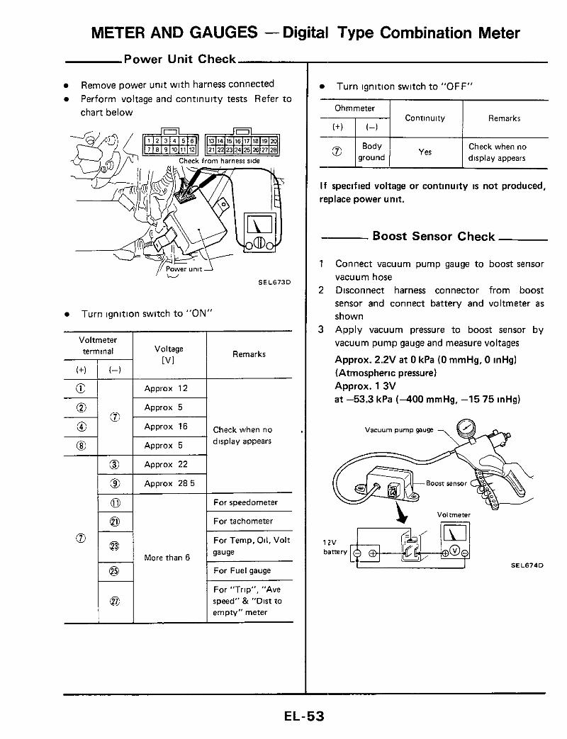
METER AND GAUGES - Digital Type Combination Meter Power Unit Check
Voltmeter terminal
( f ) (-)
E - - % ; 0 0 @I
__
@
9 0 0
Remove power unit with harness connected Perform voltage and continuity tests Refer to chart below
I Voltage
[ V I
Approx 12
Approx 5
Approx 16
Approx 5
Approx 22
Approx 2 8 5
Turn ignition switch to "ON"
1 - 1 More than 6
Remarks
Check when no display appears
For speedometer
For tachometer
For Temp, Oil, Volt sause
For Fuel gauge
For "Trip", "Ave speed" & "Dirt to empty" meter
Turn ignition switch to "OFF"
Ohmmeter Continuity Remarks
Check when no ground display appears
I f specified voltage or continuity is not produced, replace power unit.
- Boost Sensor Check
1 Connect vacuum pump gauge to boost sensor vacuum hose
2 Disconnect harness connector from boost sensor and connect battery and voltmeter as shown
3 Apply vacuum pressure to boost sensor by vacuum pump gauge and measure voltages
Approx. 2.2V a t 0 kPa (0 mmHg, 0 inHg) (Atmospheric pressure) Approx. 1 3V a t -53.3 kPa (-400 mmHg, -15 75 inHg)
vacuum pump gauge
SEL674D
EL-53
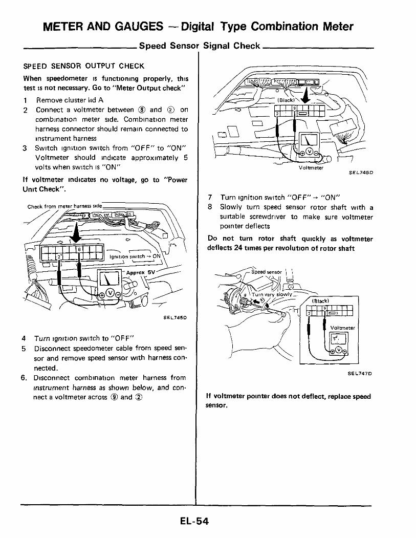
METER AND GAUGES - Digital Type Combination Meter Speed Sensor Signal Check
SPEED SENSOR OUTPUT CHECK
When speedometer is functioning properly, this test is not necessary. Go to "Meter Output check"
1 Remove cluster lid A 2 Connect a voltmeter between @ and @ on
cornbination meter side. Combination meter harness connector should remain connected to instrument harness Switch ignition switch from "OFF" to "ON" Voltmeter should indicate approximately 5 volts when switch is "ON"
If voltmeter indicates no voltage, go to "Power Unit Check".
3
SEL745D
4 5
Turn ignition switch to "OFF" Disconnect speedometer cable from speed sen- sor and remove speed sensor with harness con- nected.
6. Disconnect combination meter harness from instrument harness as shown below, and con- nect a voltmeter across @ and @
Voltmeter S E L 7 4 6 D
7 8
Turn ignition switch "OFF" + "ON" Slowly turn speed sensor rotor shaft with a suitable screwdriver to make sure voltmeter pointer deflects
Do not turn rotor shaft quickly as voltmeter deflects 24 times per revolution of rotor shaft
SEL747D
If voltmeter pointer does not deflect, replace speed sensor.
EL-54

METER AND GAUGES - Digital Type Combination Meter
Speed Sensor Si!
METER OUTPUT CHECK
Combination meter emits speed sensor signal to control E C.C.S. control unit, A.S.C D. control unit, voice warning unit and AIT control unit.
Disconnect speedometer cable from speed sen- sor and remove speed sensor with harness con- nected
1
2 Remove cluster lid A. 3 Disconnect combination meter harness from
instrument harness as shown, and connect an ohmmeter between @ and 0
Ohmmeter
S E L 7 4 8 D
11 Check (Cont'd)
4 5
Turn ignition switch "OFF" + "ON". Slowly turn speed sensor rotor shaft with a suitable screwdriver to make sure ohmmeter pointer deflects.
Ohmmeter pointer deflects twice for each rotatton of rotor shaft
Ohmmeter - S E L 7 4 9 0
If ohmmeter pointer does not deflect, go to "Speed Sensor Output Check". (Refer to back paw)
EL-55

METER AND GAUGES - Digital Type Combination Meter Fuel Tank Gauge Check
For removal, refer t o FE section
Ohmmeter terminal Float
Main gauge
Resistance value
Approx 10 - 20Q
Approx 480 - 520Q
Approx 100 - 1 1 OQ
Approx 4Q or below
Approx 870.930Q
Sub gauge S E L 6 7 5 D
S E L 6 7 6 D
-Water Temp Sensor Check - Cylinder head R H side
SEL677D
-Oil Pressure Sensor Check -
- 011 filter 7 \ \
SEL678D
Ohmmeter terminal With engine With engine
stopped 1 running (idling)
ca On +I;'''' I More than 74Q I Less than 60.Q
EL-56
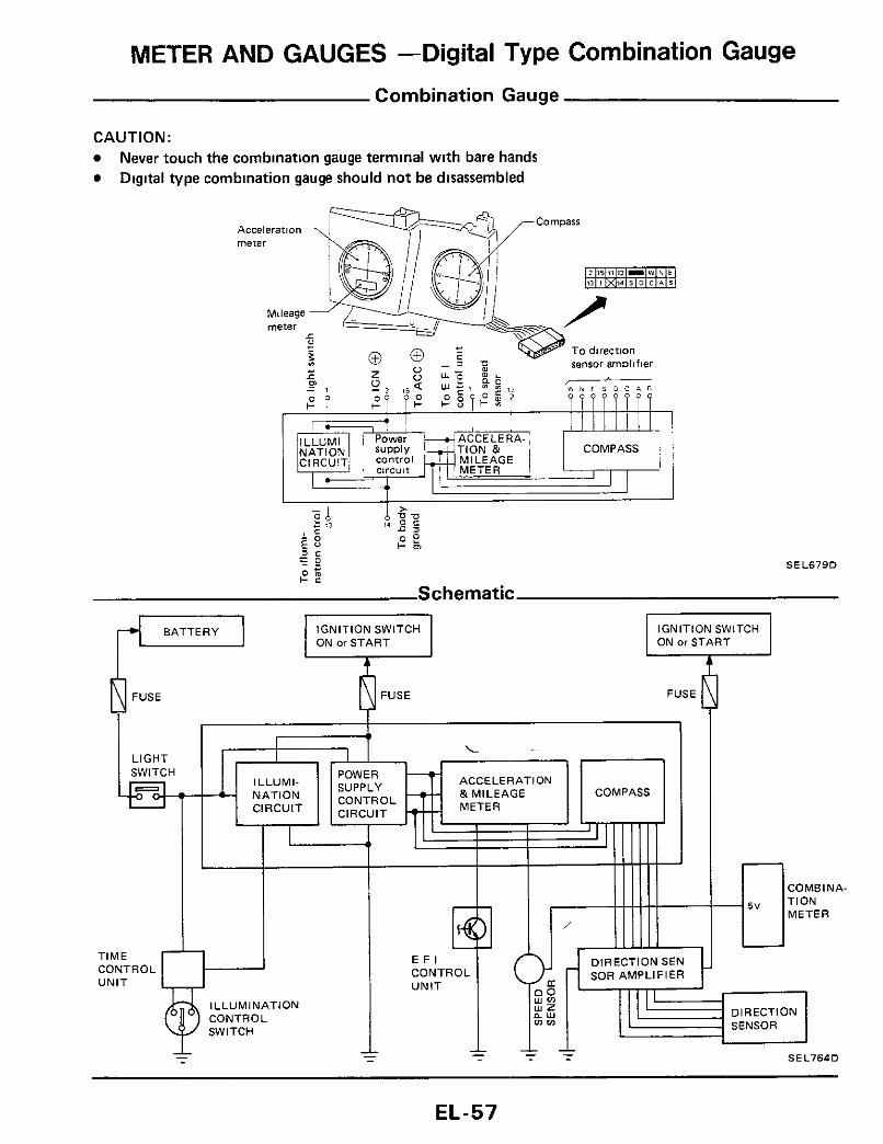
METER AND GAUGES -Digital Type Combination Gauge Combination Gauge
CAUTION: Never touch the combination gauge terminal with bare hands Digital type combination gauge should not be disassembled
ON or START IGNITION SWITCH
FUSE ~ PFUSE L-l I
1 ACCELERATION
ILLUMINATION
EL-57

METER AND GAUGES -Digital Type Combination Gauge Wiring Diagram
lOUlN03
m m
. ? I
@q . w-@ I I
SEL680D
EL-58

METER AND GAUGES -Digital Type Combination Gauge Trouble-shooting
(+)
v Check power supply circuit for combination gauge
(-1
l °K 1 N G Replace combination gauge Check harness
Voltmeter terminal I Ignition switch position
Approx Approx @ I 03 I OV I 12v ! 12v
Continuity exists @ I gK:d I Remove radio and A/C control assembly from center console and remove combination gauge with harness connected
Check from harness rtde
SEL681D
Display illumination will not darken when light 1 switch i s "ON"
I Check light switch circuit for combination gauge I
1 Remove radio and A/C control assembly and remove combination gauge with har- ness connected. Turn ignition switch to "OFF" Turn light switch to "ON" Measure voltage across @ and @
2 3 4
Ignition switch - 0 ht switch - ON
SEL682D L
EL-59

METER AND GAUGES -Digital Type Combination Gauge ,- Trouble-shooting (Cont'd)
Compass will not indicate direction in which vehicle i s being driven COMPASS
I
Face vehicle toward the North to make sure arrow points to "N"
Display deviates by one graduation . more graduations
Display deviates by two or . 1
S I O W I ~ turn volume 0 until arrow moves from @ (0) to @ ( @ I Thenslowlyreturn volume @ until arrow points to point @
When arrow deviates toward West, move switch @ to (+),when it deviates toward the East, move switch to (-) Return switch @ to Neutral when arrow stays between points @) and @
I Face vehicle toward the East t o make sure arrow points to "E" 1 Display deviates
SIOWIV turn volume @ until arrow moves from (Q (0) to @ ( @ I Then slowly return volume @ until arrow points to point @
1 Display deviates by two or . more graduations
switch @ t o ( + I , when it deviates toward the South, move switch to (4 Return switch @ to Neutral when arrow stays between points (Q and 0
I Again face vehicle toward the North to make sure arrow points to "N" 1
Direction sensor amplifier (Located on luggage compartment R H 1
, ,
Dirplav
SEL683D SEL684D
EL-60

METER AND GAUGES -Digital Type Combination Gauge Trouble-shooting (Cont'd)
Go to "Direction Sensor Check"
Arrow will not illuminate, but N, E, W. S and scale W i l l
No
Direction of arrow will not change when vehicle moves in i t s direction
I
Yes
I Go to "Direction Sensor Amplifier Output Check" I.-
No Move vehicle to a place that i s free from magnetic fields and check to see if compass functions normally
I N G v Replace direction Replace direction sensor amplifier sensor
1 GO to "Compass Input Check" I I N G
T I O K T
Replace combination Check harness between gauge compass and amplifier
All arrows illuminate
v Go to "Compass Input Check"
T I O K ! N G Replace combination Check harness between
gauge compass and direction sensor amplifier
Part of display does not appear I
Go to "Direction Sensor Amplifier Output Check"
I N G ! O K T Replace combination Replace direction gauge sensor amplifier
EL-61
METER AND GAUGES -Digital Type Combination Gauge Trouble-shooting (Cont'd)
v
IGo to "Direction Sensor Amplifier Output Check" I
1 N G v Check for loose harness connector to amplifier
Check for loose harness connector to combmatlon
Replace combinatlon gauge Replace amplifier
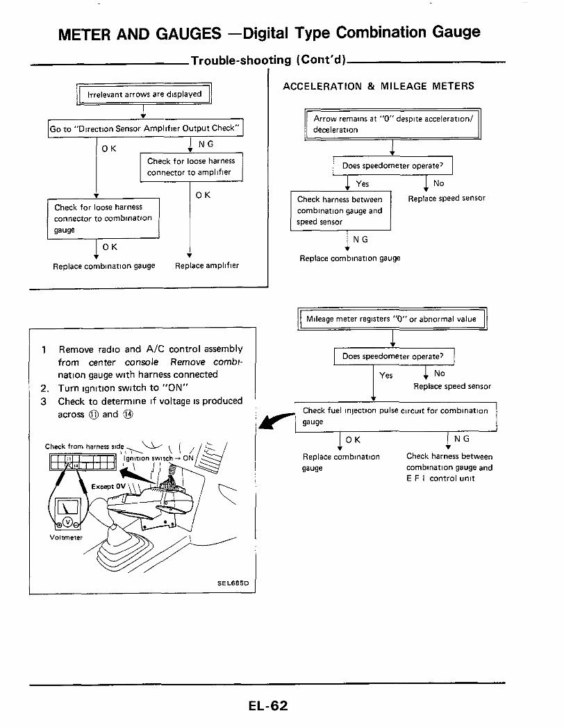
I 1 Remove radio and AIC control assembly
from center console Remove combi- nation gauge with harness connected
2. Turn ignition switch to "ON" 3 Check to determine i f voltage IS produced
across 0 and @
SELSBSD
ACCELERATION & MILEAGE METERS
deceleration
Does speedometer operate?
1 No Check harness between combination gauge and speed sensor
Replace speed sensor
lNG Replace combination gauge
Mileage meter registers "0" or abnormal value
I
Does speedometer operate?
Replace speed sensor
Check fuel injection pulse circuit for combination
gauge
I N G v Check harness between Replace combination
gauge combination gauge and E F I control unit
I O K
EL-62

METER AND GAUGES -Digital Type Combination Gauge
@ @ 6 1 0 0
1 0 0
1 0 0
1 0 0
0 1 0
0 1 0
0 1 0
0 1 0
0 0 1
0 0 1
0 0 1
0 0 1
0 0 0
0 0 0 0 0 0 0 0 0
- Direction Sensor Amplifier - Output Check
Connect direction sensor amplifier harness (if disconnected) Using a directional magnet, determine the direction in which car faces. Check voltage across terminals as indicated in chart below Turn ignition switch to "ON"
- Compass input Check
Remove radio and A/C control assembly from center console and remove combination gauge with harness connected Check voltages across terminals as indicated in chart below Turn ignition switch ON
Ch
SEL6870
Voltmeter (-1 terminal
(+)
NW
NNW
N
NNE
NE
ENE
E
ESE
SE
SSE
S
ssw sw wsw W
WNW
1 Morethan4V 0 Lessthan 1V
I -
@ - 0 0 0 0 0 0
0 0 0 0
0
0
1
1
1
1 -
- 8 - 0 1
1
1
1
1
1
0
0 1
1
1
1
1
1
0 -
- @ - 1
0
1
1
1
1
0
1
1
0
1
1
1
1
0
1 -
-
- 1
1
0
1
1
0
1
1
1
1
0
1
1
0
1
1 -
- 0 - 1
1
1
0 0 1
1
1
1
1
1
0 0
1
1
1 -
CAUTION: Before performing voltage measurements, ensure that there IS no equipment or facility which would produce powerful magnet lines in the vicinity of vehicle.
N NNW? I r N N E
WNW ENE . , w 4 w E k - E
S E L 6 8 8 D
EL-63
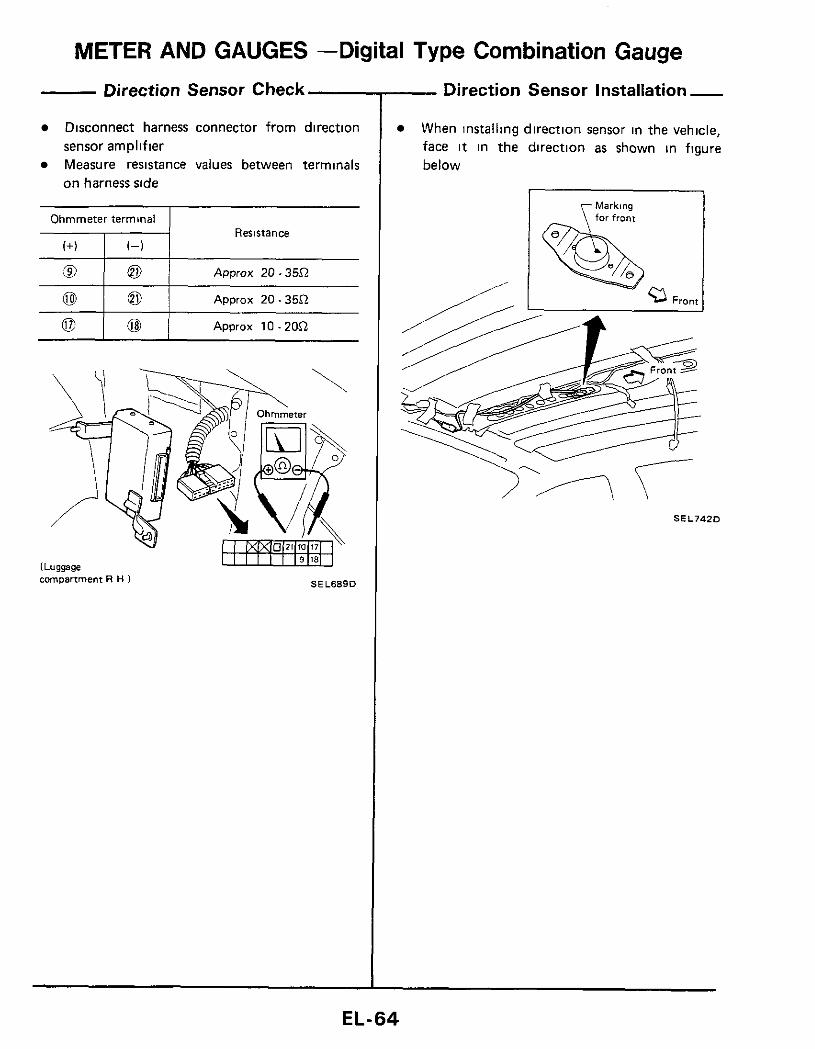
METER AND GAUGES -Digital Type Combination Gauge
@ I o
Direction Sensor Check
Disconnect harness connector from direction
Measure resistance values between terminals sensor amplifier
on harness side
Approx 20.35.Q
Resistance
0
a l o l Approx 20.35.Q
~
Approx 1O.ZO.Q
SEL689D compartment R H )
- Direction Sensor Installation - When installing direction sensor in the vehicle, face it in the direction as shown in figure below
r Markins
S E L J 4 Z D
EL-64

METER AND GAUGES -Needle Type Combination Meter Combination Meter
pj 0, SENSO
35 36 31
1 TACHO-
METER
B B p g B W * E m 8EAR
FUEL BELT DOOR BRAKE CHARGE OIL RADIATO HEAD- STOP& COOLANl LAMP T A I L
LAMP
0 32 -- a: " E
NATION 3 0
ILLUMI-
0 33 - U 18 19 20 s;14 15 5 23
24 2. 29 1 3 4 1 1
SEL690D
EL-65

METER AND GAUGES -Needle Type Combination Meter Tacho, Fuel and Water Temperature Gauges/Wiring Diagram
C z > = oc :E I
6$ m
L
m
_I
I I
Y - m -
l l l l l l I
1:
I
I 1 I 0 1 I I I I I I I I I I I
r-
SELSSlD
EL-66

METER AND GAUGES -Needle Type Combination Meter
Ohmmeter terminal ,+) , ~- , 1 Float position
Fuel Tank Gauge Check
For removal, refer t o FE section
Resistance value
Full
0 0 EmpN
112
Approx 652 Approx 8052 Approx 30 - 3552
More than 6052 Less than 652
Main gauge
Sub gauge SEL6750
SEL67SD
,-Speed Sensor Signal Check
Speed sensor is built into the speedometer Turn speedometer slowly using small screw- driver, and check continuity of speed sensor circuit
Continuity exists two times for each turn . 0 K.
SEL696D
--Speedometer Cable Removal -
\
Press to
L? connect
SEL692D
EL-67
METER AND GAUGES -Needle Type Combination Gauge Combination Gauge
I
2
P I To boost sensor
z c +
0 i m 0
Y
- b 4
SEL693D
EL-68

01 L O I L OIL PRESSURE TEMPERATURE PRESSURE SENSOR SENSOR SENSOR
I
BOOST SENSOR
v) m r
P 0
%
@ f$& BODY GROUND
m
h
(Instrument harness)
FUSE BLOCK
J
COMBINATION GAUGE
VOLTMETER
GAUGE
4
GAUGE
BOOST METER
TRIMMER
IGNITION SWITCH O N or START
I G (Main harness)
Turbocharger model
Nom turbocharger model
A/T model
M/T model
3 m -I m rn D z U 0 D C 0 rn ui I z
(D (D Q T -I Y 0 (D
0 0 3 0 ¶ 9)
9) c 0 (D
-.
E G)
METER AND GAUGES -Needle Type Combination Gauge Oil Temp. Sensor Check
1 Warm up engine 2 3
Stop engine and turn ignition switch OFF Check resistance of oil temp sensor
SEL695D
- Boost Gauge Trimmer Adjustment - When boost gauge does not give proper reading, adjust 0 kPa (0 mmHg, 0 inHg) point with the trimmer located on interlor upper wall of glove box Use a screwdriver t o adjust trimmer
For checking oil pressure sensor and boost sensor, refer to pages EL-53 and 56
EL-70

WARNING LAMPS AND CHIME
I
33tlVH3 pg I K-7
1 I dWV1 tlV3tl
M dWVlOV3H
WARNING LAMPS AND CHIME
- Warning Lamps/Wiring Diagram- For Digital Type Combination Meter- -
S E L 6 9 8 D
E L - 7 2

WARNING LAMPS AND CHIME Warning Chime/Wiring Diagram
SEL793D
EL-74

WARNING LAMPS AND CHIME Diode Check
Check continuity using an ohmmeter Diode is functioning properly if test results are as shown below
--I+-- 1 1 ,- Diode
Ohmmeter
NO continuity @ SEL700D
DIGITAL TYPE COMBINATION METER
Diodes for warning lamps are located on the panel where warning bulbsare fitted
For bulb check
For brake warning 7 f For door warning
Far door warning
For ta i l lamp warning
For radmtor warning
Far 0, sensor warning
Far headlamp warning For brake warning
SEL701D
-~
NEEDLE TYPE COMBINATION METER
Diodes for warning lamps are built into the Combination meter printed circuit
7- For 0, sensor warning
BRAKE DOOR FUEL
For bulb check
LAMP
SEL70ZD
--Warning Chime Check
A
S E L 8 7 5 D
EL-75
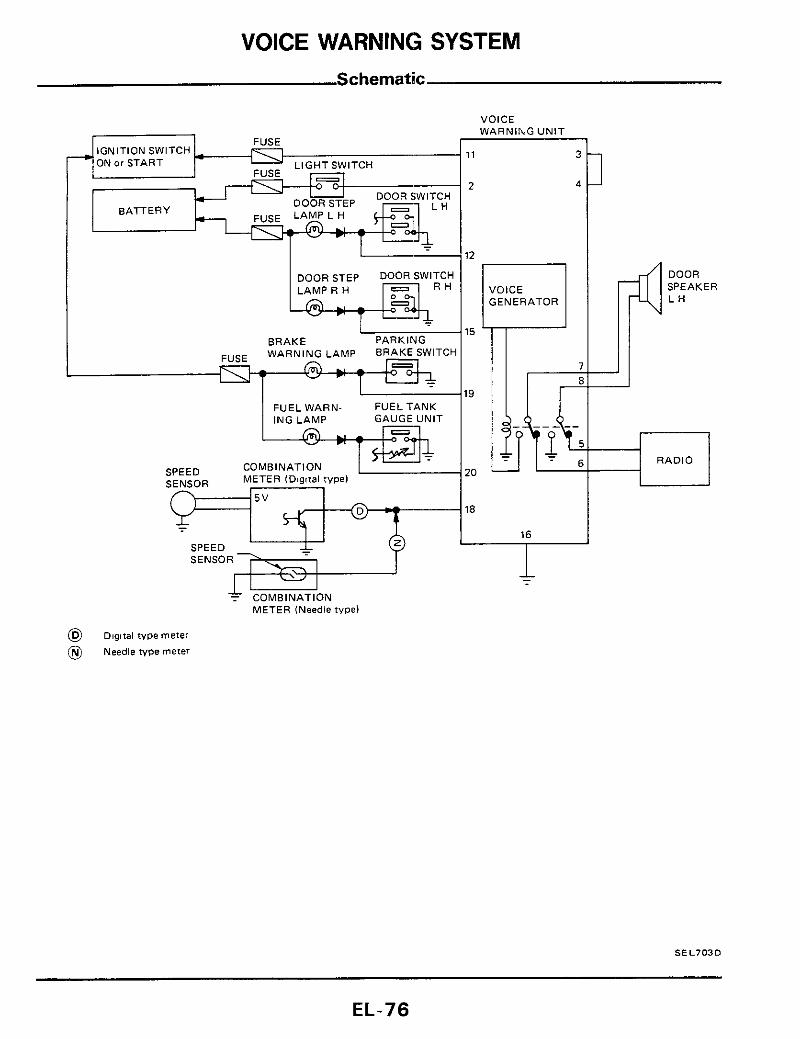
VOICE WARNING SYSTEM Schematic
I 12
DOOR STEP DOOR SWITCH VOICE GENERATOR
BRAKE PARKING WARNING LAMP BRAKE SWITCH FUSE - 1
19 FUEL WARN- FUEL TANK ING LAMP GAUGE U N I T
20 COMBINATION METER lD8gc1al type)
SPEED SENSOR
5 v 18
I
7 COMBINATION METER (Needle type1
@ Dlgltal typemeter
@ Needle type meter
1
DOOR SPEAKER L H
I
__r_l RADIO
SEL703D
EL-76
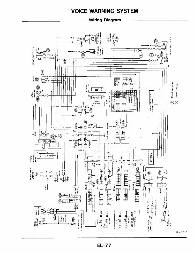
VOICE WARNING SYSTEM Wiring Diagram

VOICE WARNING SYSTEM Operational Check
Fuel level
I Condition I Voice Warning -~ ~
Item
Fuel level less than 1OP (2-5/8USgal, - “Fuel level i s low’’ 2-1/4 Imp gal)
~~
Left door
Door switch L H is “ON“
( L e f t door i s open)
ignition switch “OFF” Light
Door switch L H is ”ON” (Left door i s open)
Lighting switch is “ON” “Lights are ON”
“Left door is open”
Speed switch i s “ON” Vehicle speed is more than 10 km/h (6 MPH)
Door switch R H is ”Right door is open”
Parking brake switch Parking brake is “ON” ”Parking brake is ON”
e If rhe warning is not properly given under the above condition, go to “Trouble-Shooting”.
EL-78
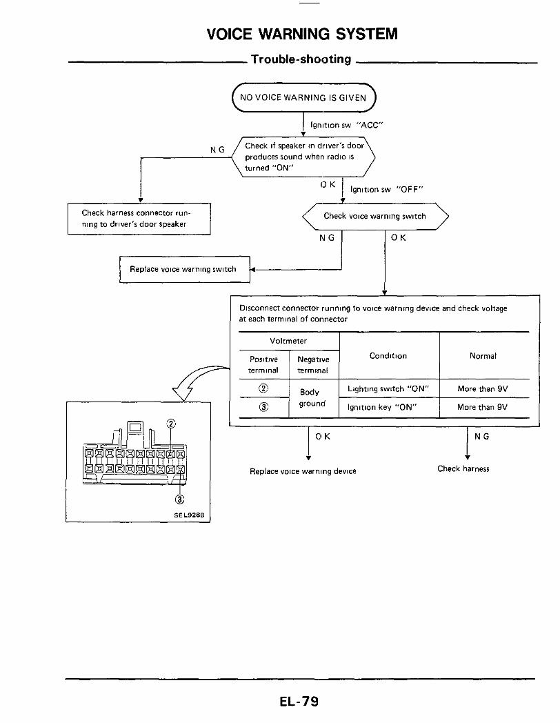
VOICE WARNING SYSTEM Trou ble-shooting
Voltmeter
Condition
1 Ignition sw "ACC"
Check if speaker in driver's door produces sound wheri radio is turned "ON"
Ignition sw "OFF"
Normal
i Check harness connector run- ning to driver's door speaker
Lighting switch "ON"
Check voice warning switch C N G >
More than 9V
Replace voice warning switch i v
Disconnect connector running to voice warning device and check voltage a t each terminal of connector
I- I I
I O K T
Replace voice warning device
I N G i
Check harness
EL-79
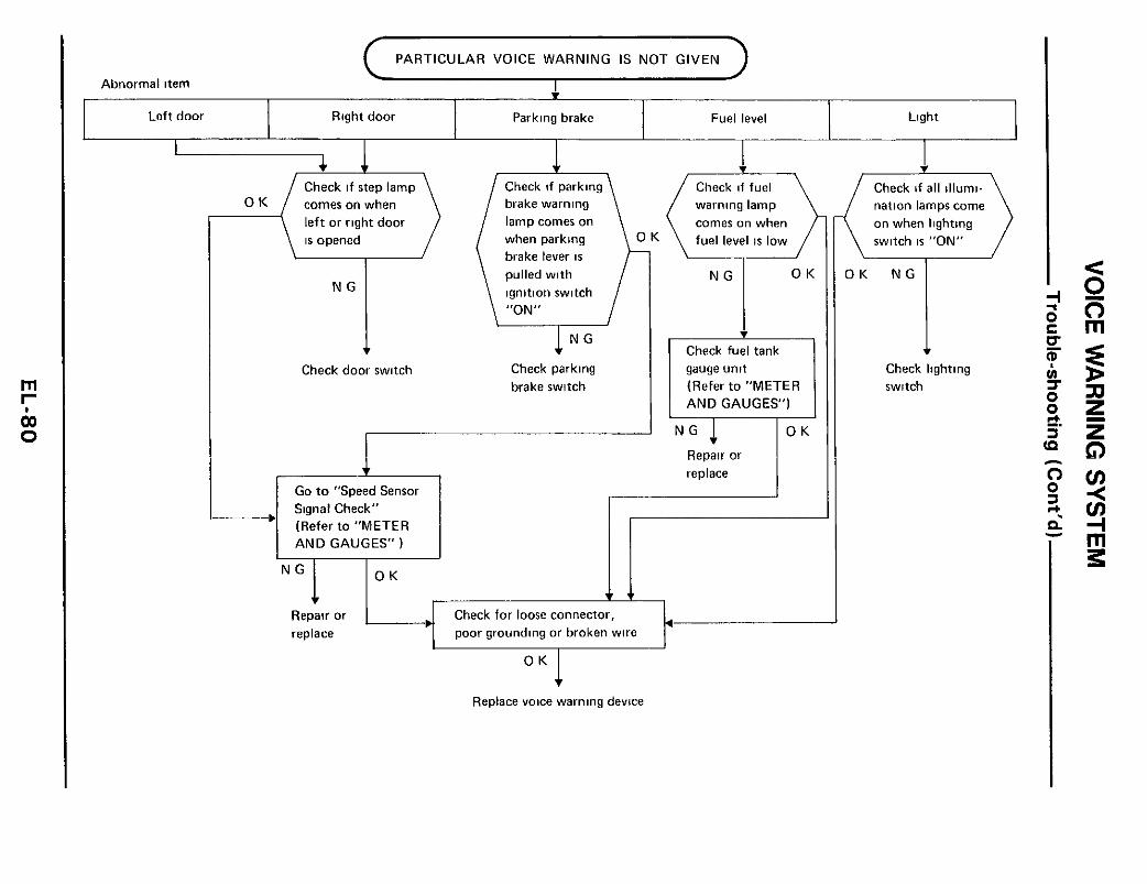
rn I-
0 do
Left door Right door Parking brake Fuel level Light
O K (7) Check if step lamp
le f t or right door is opened
Check door switch
I
I
l x e e d % Sensor Signal Check" -1 (Refer to "METER I
Check if fuel warning lamp comes on when
Check if parking brake warning lamp comes on when parking brake lever i s pulled with ignition switch "ON"
N G
Check parking brake switch
Check fuel tank gauge unit (Refer to "METER AND GAUGES")
Repair or replace
AND GAUGES" )
v Check for loose connector, poor grounding or broken wire
'""I Repair or replace
O K
Replace voice warning device
Check if a l l illumi- nation lamps come on when lighting switch is "ON"
Check lighting switch
TIME CONTROL SYSTEM
CAUTION Never touch the terminals of time control unit with bare hands.
1) Intermittent wiper control timer 5) Light warning timer 2) Interior lamp timer 6) Key warning timer 3) Door key hole illumination timer 7) Seat belt warning timer 4) Illumination control timer 8) Rear defogger timer
Time control unit has the following functions
ltNlTlON SWlTCH IGNITION lGNlTlON
FUSE
TlME CONTROLUNil / I 1
SEL705D
EL-81
TIME CONTROL SYSTEM Wiring Diagram
SEL706D
EL-82

TIME CONTROL SYSTEM
Volwnetei terminals
- Preparation for Trouble-shooting - 1 Remove R H dash side cover and remove
blower motor 2 Remove time control unit with harness con-
nected 3 Connect main harness to instrument harness (if
disconnected) Check from harness ride
Ignition switch pOI i t iOn
harness connection SE L750D
I+)
-Power Supply Cercuit Check-
1-1 OFF ACC ON
@
@ 1 @ j ov 1 ov I Approx 17v
ov Approx Approx 12v 12v 0
Contlnult"
- Trou ble-shooting
intermittent wiper does not operate
4 I Go to "Power Supply Circuit Check"
O K N G Check harness for T C U power supply circuit
v Check wiper relay circuit O K N G
I Check wiDer relav I I I I 10 K ~ N G
Check harness between Replace T C U and wiper relay
Check wiper switch circuit check
wiper relay
1 O K
I Replace T C U Check wiper switch
Check harness between T C U Replace
and wiper switch b wiper switch
v WIPER RELAY CIRCUIT CHECK
1 Turn wiper switch t o "INT" 2 Turn ignition switch to "ACC" 3 Measure voltage across and 0
Check from harness ride
fTl7rFl Wiper switch INT
0-12v lgnmon switch ACC
Needle shakes from 0 to 12V every 2 to 15 seconds
SEL708D
Voltmeter u WIPER SWITCH CIRCUIT CHECK
1 Turn wiper switch t o "INT" 2. Turn ignitionswitch to "OFF". 3 Check continuity between @ and @
Check from harness ride
Wiper switch INT Ignition switch OFF
Ohmmeter
SEL709D
EL-83

TIME CONTROL SYSTEM Trouble-shooting (Cont'd)
Intermittent time of wiper cannot be adjusted
Check intermittent wiper volume circuit
Check harness between T C U and intermittent wiper volume
Replace wiper switch
~ ~ ~ _ _ _ _ _ ~~ ~
1 2 Measure resistance between @J and @
Turn ignition switch to "OFF"
while turning intermittent wiper volume.
Check from harness side
Ignition switch OFF
0-1 kS2
Intermittent wiper knob
0 R a t S posmon
1 kR a t L postiton Approx
Ohmmeter SEL710D
combination
Check washer switch circuit
I N G f
Replace T C U Check harness between T C U and washer switch
1 2 3
Turn ignition switch to "OFF". Turn washer switch to "ON" Check continuity between @ and @
Check from harness side
lgnitjon rwrtch OFF
WASH
I Ohmmeter SEL711D
E L - 8 4
TIME CONTROL SYSTEM Trouble-shooting (Cont'd)
(Interior lamp will not illuminate when outside door handle on driver's side IS pulled 1
I
Interior lamp and step lamps do not fade out after a l l doors are closed
Check if door warning lamp goes off after all doors are closed Check if interior lamp fades out after a l l doors
are closed
O K N G Check door switch
Go to "Interior lamp circuit check" Go to "Power Supply Circuit Check"
O K N G
Check harness between T C U and interior lamp
v Check door handle switch circuit check
O K N G
Check door handle switch
Replace T C U Check harness between T c u and door handle switch
N G
Check harness between T C U and interior lamp
1
INTERIOR LAMP CIRCUIT CHECK
1 Turn Ignition switch to "OFF" 2 Measure voltage across @ and @
Check from harness ride
0 V when door 15
open 0- 12 V when door IS closed after once opened
S E L 7 l Z O
DOOR HANDLE SWITCH CIRCUIT CHECK
1 2 3
Turn ignition switch to "OFF" Pull outside door handle (driver's side) Check continuity between @ and @
Check from harness sade
I O R ye?! door handle (driver's rude)
SEL713D ohmmeter
EL-85

TIME CONTROL SYSTEM Trouble-shooting (Cont'd)
B O ,@ @
Ohmmeter
Door key hole illumination does not come on even if driver's side door handle i s pulled
I
illumination control switch
DARK BRIGHT
Except 0 R O R Excepton O R
I Go to "Power Supply Circuit Check" I Check harness for T C U power supply circuit , rK
Check key hole illumination circuit
I /OK I Check key hole illumination
Check harness between T C U and key hole illumination
Go to "Door handle switch circuit check" (Refer to back oaqe 1
l N G Check harness between T C U and door handle switch
l°K Replace T C U
1 2 3
Turn ignition switch to "OFF" Pull outside door handle (driver's side) Measure voltage across 0 and @
Check from harness side
Ignition w i t c h OFF
After outside door handle Idrlver'r ride) 16 pulled and releared, voltmeter indicates OV for about 7 seconds and then 12V
Voltmeter
S E L 7 1 4 D
Illumination control system does not actuate
Check light switch circuit
T C U and light switch
Check illumination circuit
harness connector
Check illumination control circuit
control switch
LIGHT SWITCH CIRCUIT CHECK
Check from harness side
Ignition w i t c h OFF Approx(i51j Light w i t c h ON
u SE L715C Voltmeter
ILLUMINATION CIRCUIT CHECK Check from harness side
EL-86

TIME CONTROL SYSTEM Trouble-shooting (Cont'd)
CHIME CIRCUIT CHECK
1 2
Turn ignition switch to "OFF" Measure voltage across @ and @ when driver's door is opened and closed
Check from harness ride I
I Warning ch ime does n o t actlvate
1 I Go to "Power SUDD~V Ci rcu i t Check" 1
ignition rwltch OFF Approx 12Vwhen drlver'r stde door IS closed Voltmeter needle swings (0 - 12V) when dnver's %,de door tr opened
SEL718D Voltmeter
STEERING LOCK SWITCH CIRCUIT CHECK
1 2
Turn ignition switch to "OFF" Check voltage between @ and @
Check from harness side
12V when ignmon key IS ret into key cyllndei OV when tgnltlon key 16 pulled out of key cylinder
Voltmeter SEL7190
lamp does not go off nor come on
I + Go t o "Power Supply Circuit Check" 1 1 O K 1 N G
Check harness for T c u power supply c i rcu i t
Check bel t warning c i rcu i t
O K N G
Check warning lamp
v Check seat belt switch c i rcu i t
O K 1 N G Check seat belt switch.
and harness between T c u and seat belt switch
Replace T C U
~~
BELT WARNING CIRCUIT CHECK
1 Unfasten seat belt. 2 Measure voltage across @I and @ when
ignition switch is "ON" Che& from harness ride
0 -12v Joltmeter needle keeps SwlngInQ a p p r ~ x 0-12Vl for about 7 ;econdr after ngnition wi tch I s Voltmeter :urned ON S E L 7 2 0 C
SEAT BELT SWITCH CIRCUIT CHECK
1 Turn ignition switch to "OFF" 2. Unfasten driver's seat belt. 3. Check for continuity between 0 and @ 4 Fasten driver's seat belt 5 Check to determine if continuity does not
exist between 0 and @ Check from harness %de
Ohmmeter SEL7211
EL-87

TIME CONTROL SYSTEM Trou ble-shoot
Check harness for T C U power supply circuit
I Check rear defoaqer circuit I _ _ 4 N G
I O K
Check rear defogger relay, and harness between T C U and rear defogger relay
/ I Check defogger switch circuit
Check defogger switch. and harness between T C U and defogger switch
Replace T C U
REAR DEFOGGER CIRCUIT CHECK
1 Turn ignition switch to ”ON” 2. Measure voltage across @ and @ while
operating rear defogger switch
Check from harness side
Ignition switch ON
&J Voltmeter
Apprm 12 V when rear defogger rwltch IS OFF 0 V when rear defogger switch IS ON
SEL7220
DEFOGGER SWITCH CIRCUIT CHECK Check from harness ride
Ignition switch OFF OR when rear defogger switch IS ON Except OR when rear defogger smltch I S OFF
Ohmmeter
SEL723C
ig (Cont’d)
EL-88

WIPER AND WASHER
Windshield Wiper and Washer/Wiring Diagram
. 3 1 - 0 m
D U Y
Y - I LL
U
EL-89

rn
0
I-
b
@ BODYGROUND IR H sidel
FUSE BLOCK
BODYGROUND (R H sidel p
m @
I
REAR WIPER MOTOR
- BODYGROUND
I v
m m
(Main harness)
BODYGROUND - (Back %del
BODYGROUND
I
U I@> I
(White L H ridel
WASHER (Engine room MOTOR harness1
- BOCiY SE GROUND I L H %de)
SF models
GL models
GLL models
Digital type meter
Needle type mete
WIPER AND WASHER Headlamp Washer/Wiring Diagram
HEADLAMP
RELAY WASHER HEADLAMP @
: (Back ride)
HEADLAMP WASHER SWITCH
7
- 2 2 I 1
BODY GROUND IR H ride)
HEADLAMP WASHER
BODYGROUND (L H $#de)
@ GLmodelr
@ GLLrnodelr
@ Digital type meter
@ Needle type meiei
BODY GROl ( R H ride)
I I f W h w
(Engine room harnerr)
I LIGHTING SWITCH
J
(Main harness)
USE
7/1
w I I IGNITION SWITCH I ACC or ON
I I
SEL727D
EL-91

HORN, CIGARETTE LIGHTER, CLOCK Wiring Diagram
SEL729D
EL-92

REAR WINDOW DEFOGGER Wiring Diagram
REARDEFOGGER
.L modald
SEL730D
Filament Check
1 Attach probe circuit tester (in volt range) to middle Dortion of each filament
l+ l [-I
6 volts inormal filament) SEL263
2 If a filament is burned out, circuit tester registers 0 or 12 volts
Burned out point
i + l i (-1 . . .
12 Volts SEL264
r+i I-]
SEL265 0 volts
EL-93

REAR WINDOW DEFOGGER
Filament Check (Cont'd)
3 To locate burned out point, move probe to left and right along filament to determine point where tester needle swings abruptly
/AI 1-1
SEL266
Filament Repair
REPAIR EQUIPMENT
1 Conductive silver composition (Dupont No 4817 or equivalent)
2 Ruler, 30 cm (1 1 8 in) long 3 Drawingpen 4 Heatgun 5 Alcohol 6 Cloth
REPAIRING PROCEDURE
1 Wipe broken heat wire and i t s surrounding area clean with a cloth dampened in alcohol
2 Apply a small amount of conductive silver composition t o tip of drawing pen
Shake silver composition container before use.
3. Place ruler on glass along broken line. Deposit conductive silver composition on break with drawing pen Slightly overlap existing heat wire on both sides [preferably 5 mm (020 in) ] of the break.
F u n i t Drawmg pen Ruler m m (In]
BE540
4 After repair has been completed, check re- paired wire for continuity This check should be conducted 10 minutes after silver composi- tion is deposited
Do not touch repaired area while t e s t is being con- ducted
r point
S E L 0 1 2 0
5 Apply a constant stream of hot air directly t o the repaired area for approximately 20 minutes with a heat gun A minimum distance of 3 cm (1 2 in) should be kept between repaired area and hot a i r outlet If a heat gun is not available, let the repaired area dry for 24 hours.
Repaired Point
Heat gun
S E L 0 1 3 0
EL-94

AUDIO AND POWER ANTENNA Wiring Diagram
SEL731 ID
EL-95
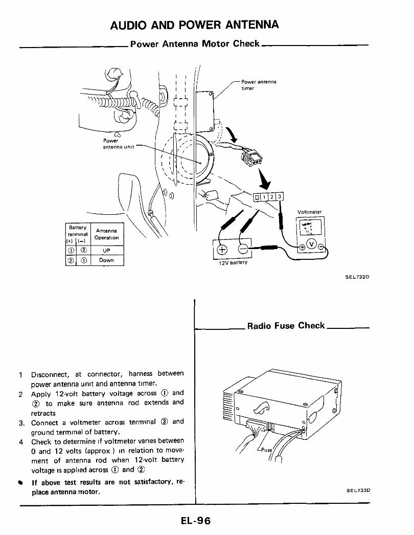
AUDIO AND POWER ANTENNA Power Antenna Motor Check
1 Disconnect, a t connector, harness between power antenna unit and antenna timer.
2 Apply 12-volt battery voltage across @ and @ t o make Sure antenna rod extends and retracts
3. Connect a voltmeter across terminal 0 and ground terminal of battery.
4 Check to determine if voltmeter varies between 0 and 12 volts (approx ) in relation to move- ment of antenna rod when 12-volt battery voltage IS applied across @ and @ If above test results are not satisfactory, re- place antenna motor.
SEL732D
Radio Fuse Check
SEL733D
EL-96

L6-13
L
T

AUTOMATIC SPEED CONTROL DEVICE (A. S. C. D.) Wiring Diagram
L
.I .. I .- i'
I
:- .I I
I - !
I
.- SEL735D
EL-98

AUTOMATIC SPEED CONTROL DEVICE (A.S.C.D.)
-Preparation for Trouble-shooting Trouble-shooting
Remove A S C D control unit with harness A S C D control unit cznnot be set properly
connected. I
Turn A S C D main switch "0FF"and then "ON" to make sure indicator (located above combination meter1 illuminates
Check for loose vacuum Check A S C D main [-I switch and A S C D relay
Check power supply circuit for A S C D control unit SEL736D
Check stop switch. clutch switch (MIT model). inhibitor relay and inhibitor switch (AIT model)
POWER SUPPLY CIRCUIT CHECK
1 Release brake and clutch pedals 2 Turn ignition switch to "ON" 3 Turn A S.C.D main switch to "ON" 4. Check voltage between 0 and @ v
Check harness between A S C D power supply Check from harness side
-+ Release
A/T control -+ ..D" range
A S C D main w n c h } - O N I O K Checksets:and
harness between control unit and set switch Voltmeter S E L S l O D
SET SWITCH CIRCUIT CHECK
1. Turn ignition switch t o "OFF". Go to "A S C D Actuator Check"
- 2 Push A.S.C.D. set switch 3 Check continuity between 0 and @
Check from harness side
tion switch 4 OFF
C 0 ret switch + ON
S E L B l l D Ohmmeter
I circuit
I Check set switch circuit for A S C D control unit 1
lNG Replace actuator
! O K * (Next page)
EL-99

AUTOMATIC SPEED CONTROL DEVICE (A.S.C. D.) Trouble-shooting (Cont'd)
Turn ignition switch to "OFF" Disconnect speedometer cable from trans- mission Connect an ohmmeter between @ and
Slowly turn speedometer cable pinion by hand t o make sure ohmmeter pointer deflects
Ohmmeter pointer deflects twice per rotation of pinion.
0.
Check from harness side
Ohmmeter SEL7630
i Check speed sensor circuit
(Digital type combination meter) -
(Refer to "METER AND GAUGES - Needle Type Combination Meter"
~~~l~~~ A S c D control unit
Check harness between A S C D control unit and speed sensor signal output terminal of combination meter
Does speedometer operate properly?
Go to "Speed Sensor Signal Check" for checking combination meter
(Refer to "METER AND GAUGES - Digital Type Combination Meter" )
Replace speed sensor
Check harness between A S C D control unit and speed sensor signal output terminal of combination meter
EL- I 00

AUTOMATIC SPEED CONTROL DEVICE (A.S.C. D.) Trouble-shooting (Cont'd)
Resume switch will not operate
Replace A S C D control unit
Check resume switch
h Accelerate switch will not owrate 11
Check accelerate switch circuit
v v Replace A S C D control unit
Check accelerate swttch
Engine hunts Q Check vacuum hose for breakage, cracks or fracture
O K lNG Repair or replace hose
v Does A S C D wire move smoothlv7
I N G v O K Repair or replace wire
I
I Go to "Actuator Check" I
O K lNG Replace actuator
.I
Replace A S C D control unlt
RESUME SWITCH CIRCUIT CHECK
1 Turn ignition switch to "OFF" 2. Turn resume switch to "ON". 3. Check continuity between @ and 0
heck from harness side
o n wi tch -+ OFF
M 0 h rn rn el e r SEL6120
ACCELERATE SWITCH CIRCUIT CHECK
1. Turn ignition switch to "OFF". 2. Turn accelerate switch to "ON" 3 Check continuity between @ and @
Check from harness %de
ignition switch + OFF
Accelerator wi tch -+ ON
SEL6130 Ohmmeter -
Large difference between set vehicle speed and actual speed
I v Check A S C D wire and actuator move smoothlv
1 N G Replace wire 01 actuator
Check vacuum hose for breakage, cracks or I fracture
4 N G I O K Repair or replace hose
I Go to "Actuator Check" 1 4 N G
Replace actuator c O K
Replace A.S C D control unit
EL-I 01

AUTOMATIC SPEED CONTROL DEVICE (A.S.C.D.) - Trouble-shooting (Cont'd)
AIT model only 0 When A S C D is set while vehicle i s operating
in "0 D " range, 0 D will be cancelled and shifting to 0 D cannot be made thereafter
0 While vehicle i s being driven using A S C D in "0 D "range, 0 D will not be cancelled even if actual car speed is 6 kmlh (4 MPH) lower than set speed (Set speed cannot be main- tained )
1 Check 0 D cancel circuit for A S C D control unit I
Replace A S C D 0 Electroniccontrolled A/T control unit Check harness between
lock-up control unit and A S C D control unit
Check harness between 0 D. cancel solenoid. i) D. cancel switch and A S C D control unit
0 Conventional A i l
I
ELECTRONIC-CONTROLLED A/T EQUIPPED MODEL (E4N71B)
Turn ignition switch to "OFF". Check continuity between @ and @
Check from harness slde . .~
ignmon switch - OFF
SEL737D Ohmmeter
CONVENTIONAL A/T EQUIPPED MODEL (4N71B)
Turn ignition switch t o "ON" Turn 0 D. cancel switch to "OFF". Check voltage @ -0 and 0-0
Check from harness side A
'-\
b 9 n d t ' ~ ~ n ~ ~ ~ ~ i ~ h O _ N 0 F i h z L Approx 12v
, I { .__. _- I .__.__.__.- -' Volmeter SEL741D
A.S.C.D. Actuator Check
1. Check continuity between terminal @ and
Continuity exist ... O.K.
terminals 0, @ and 0.
CAUTION: Do not attempt to remove valves from actuator.
2 Connect battery (approx 12V) to harness connector of actuator as shown below, and apply vacuum to actuator I f diaphragm moves smoothly, actuator IS O.K.
CAUTION. When checking actuator by applying vacuum, do not apply engine vacuum directly as it IS too strong to check actuator properly.
L A s c D actuator B,m, 112VI
SEL739D
EL- I 02
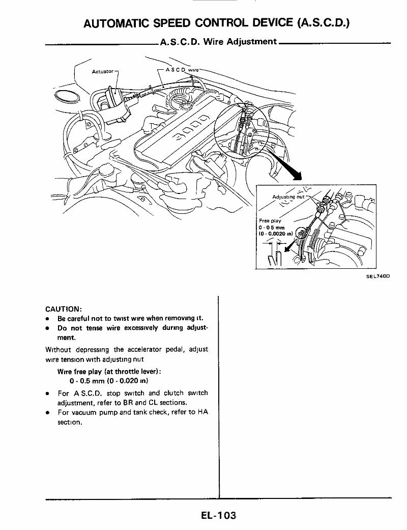
SEL740D
CAUTION: a Be careful not t o twist wire when removing it.
Do not tense wire excessively during adjust- ment.
Without depressing the accelerator pedal, adjust wire tension with adjusting nut
Wire free play (at throttle lever): 0 - 0.5 mm (0 - 0.020 in)
a For A S.C.D. stop switch and clutch switch adjustment, refer to BR and C L sections.
a For vacuum pump and tank check, refer t o HA sect ion.
EL-1 038

LOCATION OF ELECTRICAL UNITS
EL-104

LOCATION OF ELECTRICAL UNITS
hock absorber Direction sensor
Lock-up mntrol unit (For electronic controlled automatic tranmisionl
(Only for Canada digital L------ type combination meter I ~ U I D U ~ madell
Fuel pump relay r ,
(Rear side inner
SEL75ZD
EL- 1 05

LOCATION OF ELECTRICAL UNITS
LWarn ing chime Meter power unit (For digital type combination meter1
Hold relay (only for Canada analog type
Clutch wi tch (For A S C D I
(For A 5 C D )
box
SEL753D
EL- I 06

HARNESS LAYOUT
SEL754D
EL- I 0'7

HARNESS LAYOUT
Main Harness
EL- 1 08

@3 Fuse block \
T O E F I H
A S C D control unit To door harness L H White) To door harness L H (Blue) To door harness L H (SF models) To 0 (Blue) (CLL models) To @ (White) To @ (Non-turbocharger models)
. Clutch switch (A S C D )
. Stop switch (A S C D ) Stop lamp switch Step lamp L H Kickdown switch (A/T models) Lightlng switch Wiper switch Horn switch Key lamp
ul Cigarette hghter Ash tray lamp Step lamp R H To @I (Blue) To 0 W i t e ) Flasher unit Ignition switch A S C D switch Headlamp switch Intermittent wiper tune control Steermg lock swltch An conditioner harness Au conditioner harness A u conditioner harness To 0 (Non-turbocharger models) To 0 (Turbocharger models) @ To @I (Black) To @ (Blue) To @ (White) @ Tune control unit TO door harness R H (ST models) To door harness R H (CL and GLL models) To door harness R H (GL and GLL models)
@ . To @I (Blue) (GLL models)
@ Voice warning unit I@ @J
To E P I harness (Non-turbocharger models) To E P I harness

, TO TIME CON- TROL U N I T
TO INST H L H (CHIME) TO ENGINE ROOM H R H (UPHOLD RELAY)
T O ENGINE ROOM H L H IHEAO-
TO LIGHT SW TO LIGHT SW -
TO REAR
ro KEY sw
3OOM H R H A S C 0 RELAY1 To A s sw (VACUUM
ROOM H L H
PUMP RELAY)
(For time control system, headlamp system, A S C 0 and E F I system1

Diode
L & GLLxode l r
TO ENGINE ROOM
H R H (HORN RELAY]
H R H ITHEFT WARNING RELAY-11
TO ENGINE ROOM
TO THEFT WARNING CONTROL UNIT
TO HORN SWJ
TO BACK DOOR SW TOTHEFT WARNING
3 T l M E CONTROL UNIT CONTROL UNIT TO ENGINE ROOM H R H ro INST H R H
:DOOR WARNING LAMPI sw T O E F I H
TO LIGHT SW TO ENGINE ROOM H R H (POWER STEERING SWI
TO INJECTOR BLOWER IFAN MOTOR RELAY)
(For theft warning system & E F I systeml ode 6& F model9
Not used
T O E F I H TO ENGINE ROOM H R H (POWER STEERING SWI
TO LIGHT SW TO FUSE
TO REAR DEFOGGERRELAY
(For E F I system1 ode
TO TIME CONTROL
TO INST H L H
TO ENGINE ROOM H
TO KEY SW UNIT
TO ENGINE ROOM H L H (HEADLAMP MOTOR) (CHIME]
TO LIGHT SW TO LIGHT SW IUPHOLD RELAY)
TO STEP LAMP TO DOOR SW R H
TO TIME CONTROL UNIT
[For headlemp system & time control system)
Itode @ TO BACK DOOR
,LOCK SW TO DOOR SW L H
TO DOOR SW R H
TO DOOR H L H TO DOOR H R H
TO VOICE WARNING UNIT A N 0 Tl lEFT WARNING COhTROL UNIT
TO THEFT WARNING
r C O N T R O L UNIT TO BACK DOOR SW TO DOOR S W R H
TO INST H R H (DOOR WARN- ING LAMP)
TO TIME CONTROL UNIT
(Far voice warning system & theft warning system)
(Far theft warning system & tlme control system)
Turbocharger models Nan turbocharger models 2+2 seater 2 seater
Door muror defogger swtch A/T indicator lamp RcmGlc con1;a: miiiDi 8...itCh 0 D switch (AIT models) Headlamp cleaner switch Shock absorber switch (Turbocharger models) Body ground Diode Diode (Sf modcls) Diode (GL and G L L models) Diode (2+2 seater) Theft warning control unit Seat belt switch R H (GLL models) 0, Sensor control amp (GLL models) Parking brake switch Radio amphfier (GLL models) Seal bell switch L H (SF models) Seat belt switch L H (GL models) l o power seat harness (GLL models) Body ground (GLL models) Didoe (GL and G L L models) Body ground (GLL models) Body ground (GLL models)
I

/
HARNESS LAYOUT
Main Harness (Cont'd)
EL-112

@ To @ (Non-turbocharger models) 0 Ambient temp sensor 0 Vacuum tank (Turbocharger models) 0 To @I (Turbocharger models) 0 PoglampRH @ Hoodswitch 0 To @il White) @ Vacuumpump 0 I 'oglampLH
@ Hoadlamp washer motor 0 @D Horn L H / @ Side marker lamp L H
0 To @I (Blue) (Turbocharger models) @ To @ White) 0 ranmotor @ Uphold relay (Turbocharger models) @ F u u b l c h k @ Headlamp motor R H 0 Front shock absorber R H @ Radiator coolant level switch 0 Hcadlamp L H
Front combmation lamp L H
A/T relay I @ A S C D relay (Non-turbocharger AIT models) @ Water cock an valve Compressor relay 0 Headlamp R H Vacuum pump relay @ Side marker lamp R H (Turbocharger models) @ Horn R H Horn relay @ Front combination lamp R H
6 Headlamp tmer @ To @ (Blue) I@ To @ (White) @Q To @ (White) @ To 0 (Non-turbocharger models) @ Inhibitor switch (Non-turbocharger models)

\
0 To @I (White) 0 Diode (Voice warnmg system equipped 0 To @ (Blue) (GLL models) models except CLL models) 0 To @ W i l e ) 0 Speakcr R H (CLL models) 0 Jomt (POI 0, sensor warning lamp) 0 Glove box lamp switch
@O Glove box lamp @ Hold relay (Canada models) 0 @9 To (Black) @9 . To 0 (White)
To @ (Blue) (GLL models) Speak; L H (GLL models) IUumlnation control switch Instrument swtch L H Instrument swtch L H Combination meter (Black) Combination meter (While) Combination meter (White) Combination meter White) Combination meter (White) Combination meter (Blue) Combmation meter (Black) Chune Instiument switch R H Instrument switch R H
Needle type meter
Digital type meter
& Combmation gauge (CLL models) @ Combmalion gauge (SF and CL models)
TO COMBINATION METER ( B R A K E WARNING LAMPI
TO ENGINE ROOM H (BRAKE FLUID LEVEL SWI 6 TO MAIN H IPARKING
BRAKE SW AND VOICE WARNING UNIT1
[For voice warnmg system1
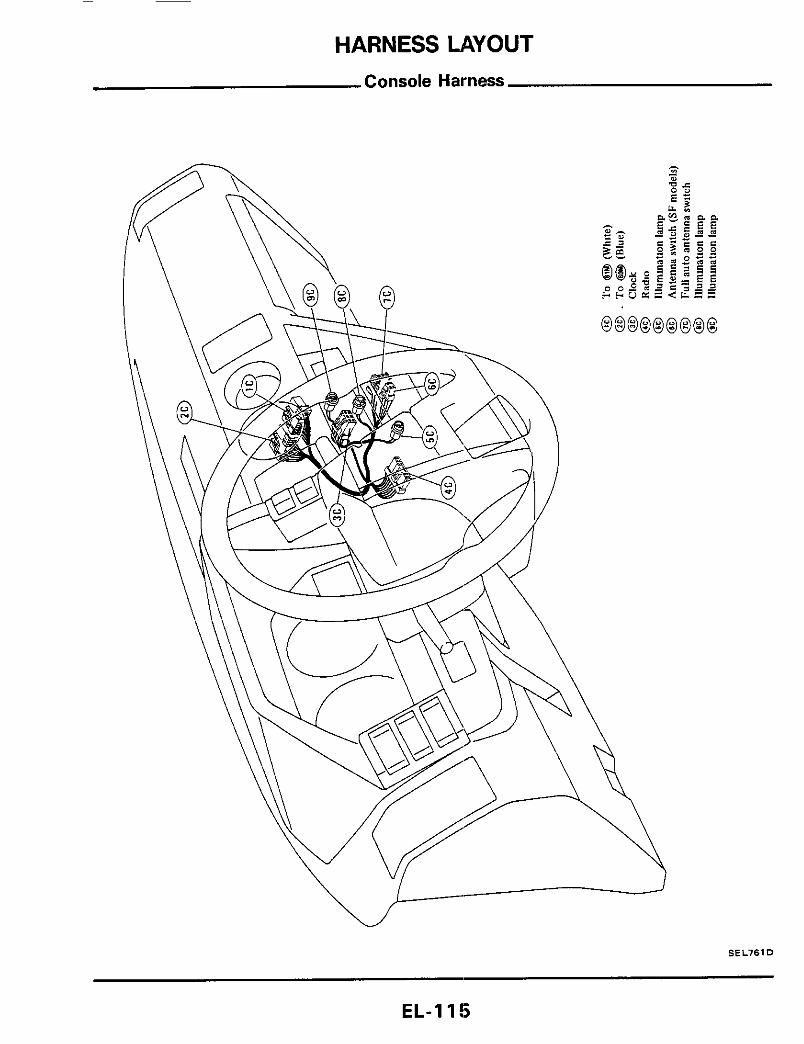
HARNESS LAYOUT Console Harness
SEL761D
EL- I 15
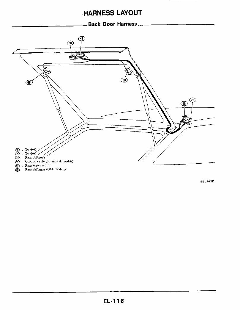
.HARNESS LAYOUT Back Door Harness
@ . Rearmpermotor @ Rear defogger (CLL models)
SEL762D
EL- I 16