electrical supply systems - ee&t lecture notes lec01 overview.pdf · industrial and commercial...
TRANSCRIPT

ELEC9713 Industrial and Commercial Power Systems
ELECTRICAL SUPPLY SYSTEMS
1. Overview Industrial and commercial power systems represent a microcosm of almost the full gamut of electrical supply systems with, in addition, a significant range of other more specialised applications of electrical, electronic, communications and electrical energy utilization systems. The term “building” will be used in this course to include any industrial and commercial installations with substantial internal electrical distribution infrastructure. It will thus include both commercial high-rise buildings and factory sites with electrical supply at up to 11 kV and with the possibility of both 11 kV and extensive 415 volt distribution systems. The focus will be on electrical distribution and associated aspects for industry and commerce. In many respects the features discussed will be effectively the same as for utility distribution systems, although they are more spatially extensive and have some features that are not found in industry and commercial systems (for example the protection schemes are a little more complex for the utility systems, and they will become more so when renewable supply is embedded in utility distribution). We will not discuss overhead lines in any detail, only cables.
ELEC9713: Industrial and Commercial Power Systems p. 1

In the current state of the art in the supply of electrical energy for such “building” services, there is an increasing need to make the overall electrical systems in large commercial buildings and in substantial industrial sites -
more energy efficient, with better energy management of loads and supply systems
safer in all aspects (including personnel safety, fire and equipment safety)
of adequate power quality with regard to harmonics and over-voltages (harmonic content is a major issue)
able to accommodate modern information technology systems (eg “smart grid” type applications)
be compliant with the new EMC and EMI regulations for electrical supply systems and for loads
provide monitoring systems to assess the condition of the electrical installation (preferably on-line).
Because of the potential dangers to personnel, safety precautions are stringently applied and there are a large number of codes, standards and regulations that have to be complied with in the electrical system design and operation. Modern OHS requirements impose a Duty of Care on the infrastructure operator and make the safety of personnel a matter of paramount importance. The aim of these codes is to give safe operation for both personnel and equipment. A detailed knowledge of these regulations is necessary for the design and operation of building electrical systems.
ELEC9713: Industrial and Commercial Power Systems p. 2

In Australia, the major overall requirement is compliance with the Australian Standard AS/NZS3000, the Electrical Wiring Rules: such compliance is a statutory requirement which is called up in the Regulations of the appropriate electrical supply system legislation of the various Electricity Acts in all of the Australian States and Territories. AS3000 is now based on international standards for such electrical installations. Until 2000, the Australian Wiring Rules were based on committee development in Australia over a period of about 80-90 years. However, as with many other countries Australia is moving towards having international standards and so the latest Wiring Rules, published in 2007, are based, to a considerable extent, on the IEC (International Electrotechnical Commission) Standard IEC60364, Electrical Installations, which is the basic international standard for low voltage electrical distribution and utilization installations. The Wiring Rules provide basic requirements for personnel (public and private) interaction with low voltage sup-ply systems. It also specifies earthing methods, cable sizing, voltage drop limits, load estimation, switchgear requirements etc. In addition to AS/NZS3000, there are many other Australian Codes and Standards which are required to be complied with in building electrical systems and in the various items of electrical equipment used in building services. Many of these are generally applicable to any electrical system, but many are quite specific to building services applications. These documents will be referred to from time to time during the course.
ELEC9713: Industrial and Commercial Power Systems p. 3
2. Power requirements The type of electrical supply system used in a commercial building or a factory depends primarily on the total power requirements of the various utilization activities that are taking place within the building or factory site. These power demands must be estimated accurately before the details of the electrical supply configuration can be determined and designed. They will determine the ultimate form (and voltage level) of the supply system to and within the building/site. The power requirements for new systems are obtained by an estimation of the maximum demand for electrical power. This will normally have four possible components that must be quantified:
manufacturing equipment requirements general fixed wiring infrastructure requirements general free-standing mobile equipment supply (GPOs) Expansion of the load supplied: eg new processes.
An estimate will require detailed loading and duty cycle estimates of each of these. In the first of these, this is easily done as the manufacturing load is easily calculated. It may include large motors, arc furnaces, power electronic equipment, welders, assembly lines, ovens, presses. Some of these loads may require special supplies, such as constant voltage, low harmonic, low noise systems.
ELEC9713: Industrial and Commercial Power Systems p. 4

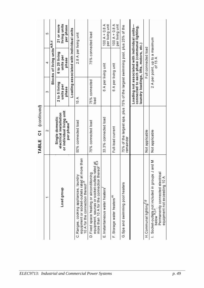
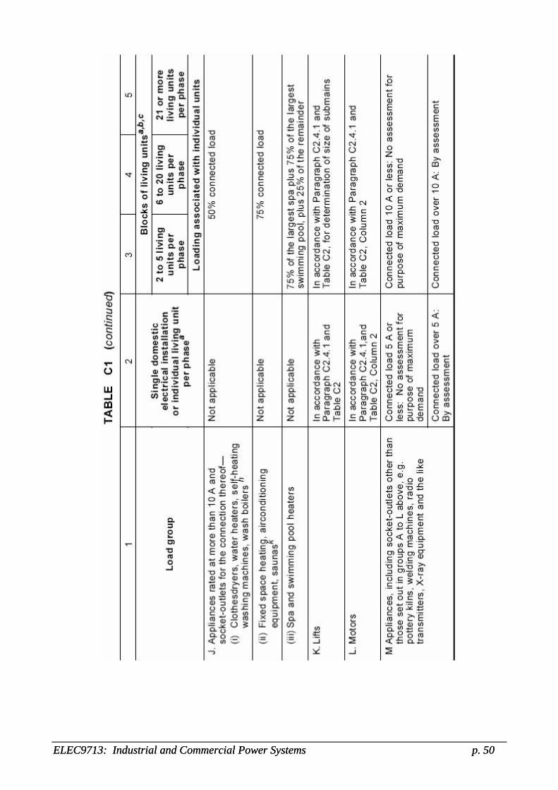
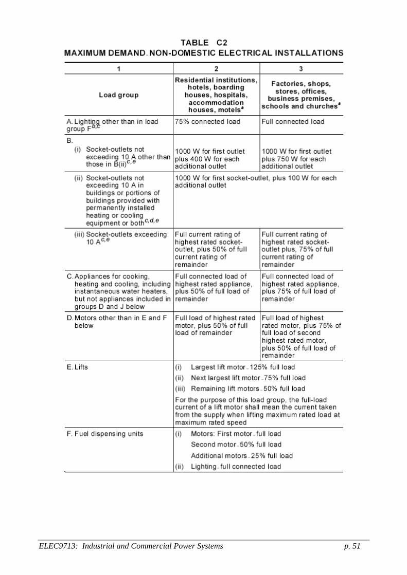
In the second area, the total of all permanently installed infrastructure equipment such as heating, lighting, air-conditioning, lifts and any similar motor drives etc must be determined. The Wiring Rules has tables which will allow determination of typical levels of such loads for buildings. In the third component, the estimate takes account of the number of general purpose power outlets (GPOs) in the building. In this last component, the method of determination of maximum demand for domestic and commercial type loads is specified in the Wiring Rules (Australian Standard AS3000, or the equivalent in other countries). The general details of the method of determination are shown in the attached details. (Tables C1 and C2 from AS3000). The estimate of future expansion is not easy to do in private industry and commerce. In the public utilities however there is accurate historical data to base a decision on. When the exact load details are unknown, an estimation technique called ‘After Diversity Maximum Demand’ (ADMD) is often used. Based on results from similar installations, typical load power density values (VA/m2) are derived for different types of floor area usage. Data for commercial (e.g. offices, shopping centres, hotels, theatres), light industrial premises and other similar buildings can be obtained from distribution utilities. The following is from EnergyAustralia NS0112 Design Standards (which is now also included in AS3000, see Table C3):
ELEC9713: Industrial and Commercial Power Systems p. 5
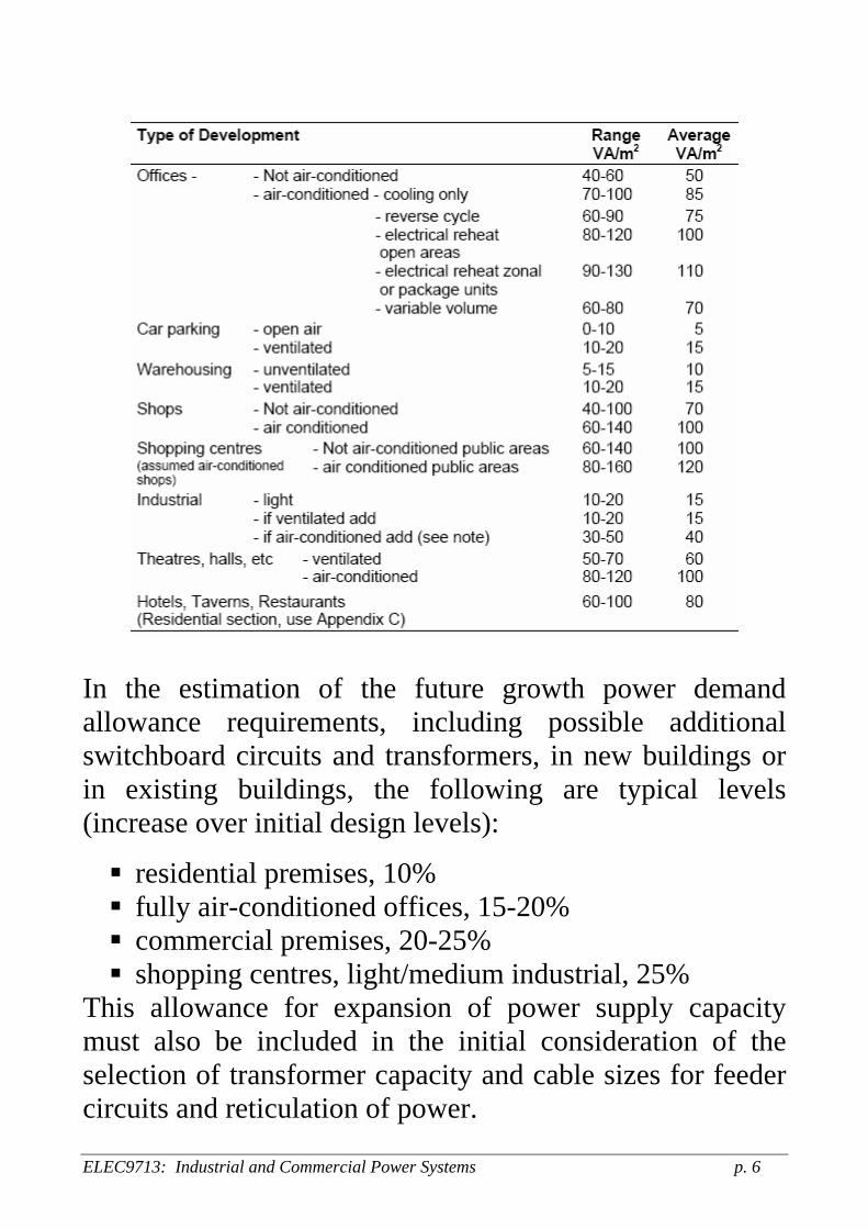
In the estimation of the future growth power demand allowance requirements, including possible additional switchboard circuits and transformers, in new buildings or in existing buildings, the following are typical levels (increase over initial design levels):
residential premises, 10% fully air-conditioned offices, 15-20% commercial premises, 20-25% shopping centres, light/medium industrial, 25%
This allowance for expansion of power supply capacity must also be included in the initial consideration of the selection of transformer capacity and cable sizes for feeder circuits and reticulation of power.
ELEC9713: Industrial and Commercial Power Systems p. 6

Once the power demand estimation is made and the required incoming supply is specified, the requirements can then be detailed for the incoming cable rating, the main transformer capacity, the substation size and capacity and the switchboard size and capacity. Only when this final design is completed can fault level calculations be performed to determine fuse and switchgear ratings and other protection needs. There are three requirements that must be considered in choosing cable sizes. These are: (a) current carrying capacity, (b) voltage drop between supply and load. (c) temperature rise under fault current conditions The first two are normal and the third abnormal operation. In normal operation, the first two requirements are not always consistent with each other’s requirements. For example an adequate current carrying capacity may give too high an impedance of the cable and thus too high a voltage drop. Then, to achieve an adequate voltage drop (which is specified as a percentage in the Wiring Rules) it may be necessary to use a cable with much larger cross-section than is needed to carry the normal load current. In such cases the voltage drop requirements must take precedence as the minimum levels in the Rules (usually about 5%) must be complied with. Use of a larger cross-section may also be necessary to limit the temperature rise under fault conditions.
ELEC9713: Industrial and Commercial Power Systems p. 7

ELEC9713: Industrial and Commercial Power Systems p. 8

3. Means and Requirements of Electrical Supply The requirements of the electrical supply system may include consideration of any or all of the following features:
Specified voltage levels Limited harmonic content (quality of supply) Method of supply Safety of supply Reliability of supply Maintenance Electrical protection Back-up supply (UPS) DC supply
3.1 Voltage Level The supply voltage levels which are available from the electricity supply utilities for use in commercial and industrial locations in urban areas are, typically:
High Voltage distribution: 11 kV, 3-phase supply [by cable or overhead line] 22 kV is more commonly used in Victoria
Low Voltage distribution: (a) 230/400 volts, 3-phase, 4-wire system
(b) Single-phase, 230 volts, 2-wire system (c) Single phase 230/460V 3-wire system
[by underground cable, aerial cable or overhead line].
ELEC9713: Industrial and Commercial Power Systems p. 9
[Although the nominal 240/415V designation is still common terminology (and use), Australia and other countries are moving to the standardised 230/400 V system.] Other supply voltages or configurations may be available in some specific locations, for example in rural areas and for some large industrial installations, but these would be relatively rare exceptions to the above options. Once the power demand and supply requirements are determined by the system designer (usually an electrical consulting engineer), it is necessary to then contact the electricity distributor. They will have a range of additional requirements which must be complied with before they will connect supply from their network to the site. Note that the electricity provider (the retailer) may be different from the actual electricity distributor who owns the supply lines and infrastructure, in line with the new regulations which allow contestability among all electrical utilities (and others) in the supply of electricity to consumers. Each electricity distributor is licensed to operate its distribution system over a designated geographical area. In all, there are 3 electricity distributors [DNSPs or Distribution Network Service Providers] covering the state of NSW: EnergyAustralia, Integral Energy, and Country Energy.
ELEC9713: Industrial and Commercial Power Systems p. 10

DNSPs in Eastern Australia [Source: AER, Elect Dist Ch.6] There are nine electricity retailers licensed to sell electricity to consumers in NSW: the retailers pay rental to the DNSPs for use of their networks. Note that each Australian state sets its own requirements on electricity supply connection. In NSW in particular, these requirements are laid out in the Code of Practice “Service
ELEC9713: Industrial and Commercial Power Systems p. 11

and installation rules of NSW: the electricity industry standard of best practice for customer connection services and installations” (2009 edition), published by the NSW Government, Department of Water and Energy. Also, each distributor may impose further requirements. For example, see “ES1 Customer Connection Information” (2007) by EnergyAustralia.
Retailers of electricity in Australian states as at 2009
[Source: AER Elect Distbn Chapter 6, 2009]
ELEC9713: Industrial and Commercial Power Systems p. 12

3.2 Quality of Supply This is now an important consideration in the operation of electrical supply systems in buildings, for two main reasons:
1. The increasing use of power electronics has introduced a higher harmonic level into the supply voltage and this can have deleterious effects such as the increase of losses in equipment such as transformers and motors with iron cores.
2. Much of the equipment now in use (particularly IT
items) is now more susceptible to voltage variation, transient overvoltages and harmonics.
The main features of quality of supply that must be considered in the design of building and industrial sites installations are:
Steady state voltage/ voltage regulation Frequency of AC supply Voltage sags. Voltage swells Voltage waveform distortion Transient overvoltages interference with communications & control equipment Outages per year [SAIFI] Duration of outages per year [SAIDI]
ELEC9713: Industrial and Commercial Power Systems p. 13
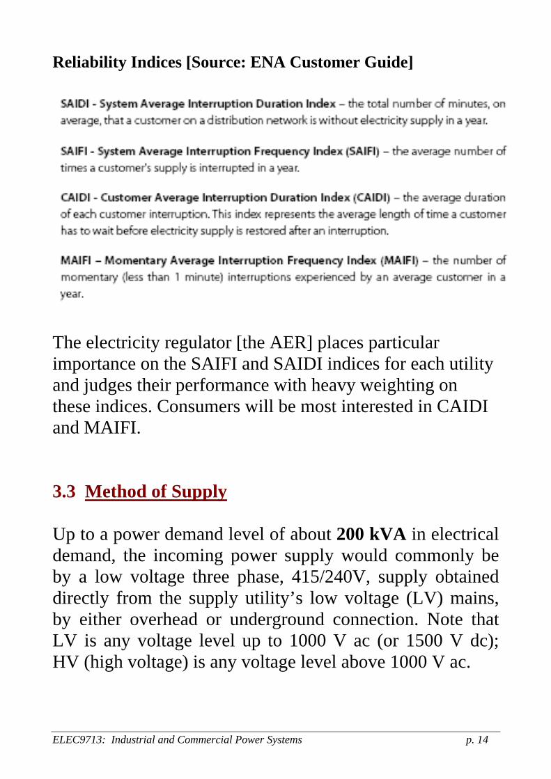
Reliability Indices [Source: ENA Customer Guide]
The electricity regulator [the AER] places particular importance on the SAIFI and SAIDI indices for each utility and judges their performance with heavy weighting on these indices. Consumers will be most interested in CAIDI and MAIFI. 3.3 Method of Supply Up to a power demand level of about 200 kVA in electrical demand, the incoming power supply would commonly be by a low voltage three phase, 415/240V, supply obtained directly from the supply utility’s low voltage (LV) mains, by either overhead or underground connection. Note that LV is any voltage level up to 1000 V ac (or 1500 V dc); HV (high voltage) is any voltage level above 1000 V ac.
ELEC9713: Industrial and Commercial Power Systems p. 14

Up to 3000 kVA, the supply method would be by utility-owned transformer(s) installed in a utility-owned and maintained substation, typically located on the consumer’s premises. The supply to the consumer’s electrical system (at the point of attachment to the consumer’s terminals) would be at low voltage (415/240V) from the secondary of the transformer. The individual transformers used would be units of 11kV/415V and typically 750 – 1000 kVA in power rating. They would normally be oil-filled transformers if installed outdoors or possibly dry-type transformers if installed inside a building. Dry-type units are used to reduce fire hazards within buildings. They are insulated by having the windings cast in epoxy resin or by having varnished paper insulated windings exposed to the air. At maximum power demands of greater than 3000 kVA, the supply to the consumer would be at high voltage, most likely 11 kV, with the consumer providing and owning the HV substation and switchgear installation (and handling the maintenance and switching operations associated with the substation). In this case the consumer would be required to employ electrical staff or contractors adequately trained in the maintenance and operation of high voltage equipment. In applying for connection to the utility system, the consumer must notify the supplier of any expected abnormal operating characteristics of operation. This may include, for example, current and voltage surges and non-linear loads which may be significant harmonic generators. The utility supplier will also require details of protection
ELEC9713: Industrial and Commercial Power Systems p. 15
device settings in the consumer’s systems, so that appropriate discrimination with the utility protection operation can be achieved and an adequate earthing system installed. 3.4 Type of Supply Connection The supply system configuration and connection to the consumer may be by means of any of the following systems: (a) High or low voltage from the distribution supply, by
either: Aerial (overhead) lines (with either bare, covered or bundled insulated conductors)
Underground cables (either 3 single phase or 1 3-phase cable)
(b) Low voltage supply from a utility on-site substation, by
means of any of: Low voltage aerial (overhead) lines (bare, bundled or covered conductors)
Low voltage underground cables (usually 3-phase)
Low voltage busbar trunking system with bare rectangular section copper or aluminium bars (greater than 2000A per phase)
(c) Dedicated high voltage line from a utility HV
substation. This may be by either overhead line or
ELEC9713: Industrial and Commercial Power Systems p. 16

underground cable, depending on the location and the requirements.
[For example, UNSW is a high voltage customer and receives its electrical power at 11kV from two separate connection points to the EnergyAustralia 11kV distribution system. It (UNSW) then operates its own 11kV distribution supply system within the campus. Larger consumers such as the Bluescope steelworks in Port Kembla take supply at 33kV from Integral Energy with four 33kV overhead lines giving supply.]
3.5 Safety Safety regulations require adherence to all relevant Codes and Standards for the applications of the installation. In general, all personnel safety and other general hazards such as fire precautions are covered by the Wiring Rules and its associated documents. [Other general safety aspects include lifts, emergency lighting, fire extinguishing systems, hazardous atmosphere areas etc.] However there are also likely to be other specific hazards which can arise depending on the installation and its loads. These may require isolation of machinery, hazardous areas, equi-potential areas, anti-static locations etc.
ELEC9713: Industrial and Commercial Power Systems p. 17

3.6 Reliability of Supply The level of reliability depends on the application. Process industry requires high reliability, while commercial operations are less dependent on reliable supply, although computer systems need high reliability. In some cases back-up supply may be required with fast transfer when utility supply fails. Factors to be considered when designing for reliability include:
Supply voltage level (HV supply at 11 kV is more reliable than LV)
Redundancy in circuits (ring mains rather than radial systems)
Proper protection design (discrimination, etc) Earthing (in some cases, isolated systems may use high impedance earthing to improve reliability)
Proper maintenance of equipment Choice of equipment.
3.7 Maintenance This is a major issue in current electrical systems. General requirements may include:
Moisture control to prevent degradation of insulation Ventilation and cooling to maintain tolerable temperatures
Corrosion (particularly of earthing if DC is used) Regular visual inspections Regular testing Regular monitoring and record keeping and analysis
ELEC9713: Industrial and Commercial Power Systems p. 18
The major issue relates to testing and monitoring and whether to use:
Regular routine testing Testing as required (condition based maintenance) Reliability centered maintenance and testing
Currently the last of these (RCM) is the favoured method in terms of the optimal compromise between cost and efficiency of maintenance. 3.8 Back-up supply Many applications require some form of back-up electrical supply, whether it is just for basic systems or for maintenance of full supply. Un-interruptible supply systems (UPS) are becoming more common in building services. Back-up systems may be via diesel generators with UPS being battery-operated power electronic inverter systems. Whether a diesel generator or a UPS is required depends on the required speed of power take-up. Diesel generators may take many seconds to start up and provide supply while UPS systems are able to start up with no effective delay. UPS can also serve to provide some filtering function of the utility supply to improve power quality. 3.9 DC supply
ELEC9713: Industrial and Commercial Power Systems p. 19
In some situations, mostly in industrial locations, there may be a need for a DC supply for adjustable speed motors, for electrolysis or other purposes. Generally the means of obtaining DC are by modern power electronic converters although older installations may still use rotating machine DC generators driven by AC motors or even mercury arc rectifier systems in very old installations. There is a recent move to provide commercial buildings with high densities of IT equipment in them with a low voltage DC supply able to power the IT equipment and doing away with the use of many inefficient (in terms of power) transformers for each item of equipment. 4. In-house Distribution Systems Once the maximum demand and the form of supply are decided on, the internal electrical distribution system must be designed by (usually) the consulting engineers. The circuit supply layout design will be determined by the size of the load, the reliability required, the voltage level and the diversity of the load. Some typical internal supply configurations are shown on later pages. The configurations are generally determined according to requirements of reliability and demand. For example a ring main system may be required for allowing alternative supply to any location, or a primary selective radial system may be preferred. In simple small system a basic radial system is used: this can be increased to an
ELEC9713: Industrial and Commercial Power Systems p. 20
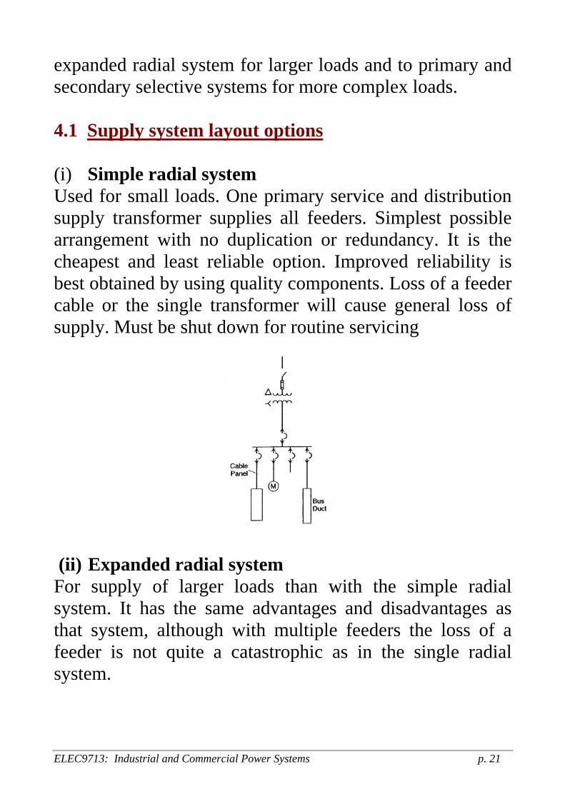
expanded radial system for larger loads and to primary and secondary selective systems for more complex loads. 4.1 Supply system layout options (i) Simple radial system Used for small loads. One primary service and distribution supply transformer supplies all feeders. Simplest possible arrangement with no duplication or redundancy. It is the cheapest and least reliable option. Improved reliability is best obtained by using quality components. Loss of a feeder cable or the single transformer will cause general loss of supply. Must be shut down for routine servicing
(ii) Expanded radial system For supply of larger loads than with the simple radial system. It has the same advantages and disadvantages as that system, although with multiple feeders the loss of a feeder is not quite a catastrophic as in the single radial system.
ELEC9713: Industrial and Commercial Power Systems p. 21

(iii) Primary selective system
Allows the possibility of alternative supply from two separate sources on the primary side of a number of transformer(s). Gives improved reliability. This method has two separate primary feeders which can be switched as required. When one supply is lost, any load can be transferred to the other supply source by automatic or manual switching. The sources can be paralleled. Maintenance is now possible without loss of supply. This method has higher cost than the radial systems due to the necessary duplication of components such as switchgear and cables.
ELEC9713: Industrial and Commercial Power Systems p. 22

(iv) Primary loop system
This system gives greater reliability in the case of failure of the primary cable that makes up the loop system. Each load can be supplied from either end of the cable in the event of a fault in the cable. Finding the cable fault may be difficult in some cases however. Requires several closures to find a fault, so may be dangerous. One section may be energized from either end. Primary selective system is a better option.
ELEC9713: Industrial and Commercial Power Systems p. 23

(v) Secondary selective system This is achieved when pairs of unit substations are connected through a normally open secondary tie circuit breaker. If the primary feeder or transformer fails, the main secondary feeder CB is opened and the tie CB closes. The general operation of the secondaries is as radial systems. Maintenance is possible. Good reliability. Requires consideration of loading should there be a sustained loss of one circuit.
It is possible to combine this system with a primary selective system to increase reliability if required.
(vi) Secondary spot network
In this configuration, large loads are supplied from one single common secondary busbar which has a number of parallel primary feeders connected to it. Uses special protection in the form of circuit breakers to each secondary connection. If a primary feeder fails, the protector CB is designed to prevent reverse fault in-feed by opening in such an event. This is the most reliable system for large loads, but is expensive.
ELEC9713: Industrial and Commercial Power Systems p. 24

Used extensively for low voltage, high load density applications such as large commercial buildings. Rarely used in industry however.
(vii) Ring bus system
This configuration will automatically isolate a fault. No interruption of supply for single faults. Note the number of switches and CBs used: the cost is quite high. Allows safe maintenance without loss of general supply.
ELEC9713: Industrial and Commercial Power Systems p. 25
The design layout will then require a number of specific component parts to make up the system. The components will not all be required in all cases and will depend on the supply voltage and whether the customer needs to have dedicated substations. The following gives the full range of requirements needed for such an installation: 4.2 Substation This will include the following items of equipment, within a general enclosure, which may be an open air location, an enclosed building, a “padmount” substation, a pole top substation or an SF6 gas insulated system:
the general enclosure, the transformer(s), Incoming cable/overhead line terminations HV switchgear/switchboards LV switchgear/switchboards Outgoing cables/overhead lines the overcurrent/short circuit protection system, lightning protection system An earthing grid backup battery systems, monitoring equipment for energy, voltage, current, power factor etc
4.3 Switchboards (switchgear assemblies) The switchboard will comprise primarily the output feeder cabling to the various loads (or floors of the building for
ELEC9713: Industrial and Commercial Power Systems p. 26
example) together with their separate switchgear and protection systems and the main switchgear unit. The switchboard will also have an internal busbar system with rectangular bare busbars used to interconnect the various feeder circuits. The switchboard itself may be either high or low voltage and will include the following components:
switchgear (fuses, contactors, circuit breakers) protection means (relays, fuses, CTs), protection coordination (discrimination), internal arcing detection, busbar connections to sub-circuits etc.
Switchboards are generally quite specific in design and need to be designed for each application as required. It is only in domestic and similar low power level situations where a standard switchboard design is normally used. 4.4 Cables, Busbars etc The type of cable or busbar choice is very important: a number of factors must be considered in choosing the inter-connecting conductor configurations:
current (thermal) ratings, insulation ratings fire performance, segregation of circuits, bundling of cables (effect on thermal rating), magnetic fields and any potential interference effects IP [International Protection] requirements to prevent contamination ingress.
ELEC9713: Industrial and Commercial Power Systems p. 27

4.5 Voltage regulation and power factor Voltage regulation and its associated determinant of voltage drop are very important factors in building service design (and in any electrical supply system, for that matter). An excessive voltage drop (leading to lower than rated voltage at the equipment) can cause overheating with some equipment (rotating machines for example) and lamp dimming and flicker in lighting for example. There are strict voltage level requirements in AS3000 and voltage regulation or power factor correction may be necessary to keep voltage drop within limits at maximum load. Industrial/commercial loads require significant reactive power (kVArs), e.g. motors, furnaces, electric discharge lighting. Large customers must maintain the overall load p.f. to be not less than 0.9 lagging. There is a tariff surcharge if this is not done. There are no restrictions on where to install p.f. correction equipment in the circuit. For more details, refer to Section 6 of NSW SIR (Capacitor installations). The following diagram shows the most general form of one-line diagram of a building distribution system. The incoming supply feeds a high voltage distribution switchboard which may supply a number of circuits in a ring main, for example. The switchgear will be normally contained in withdrawable rackmount units. Each switchgear will then supply an 11000/415V transformer which will then provide supply to a main 415 volt
ELEC9713: Industrial and Commercial Power Systems p. 28
switchboard (or “Switchgear and Controlgear Assembly” (SCA) to give it its correct title) in the substation. The switchboard is comprised of a number of “Functional Units” which are essentially moulded case circuit breaker (MCCB) or similar units. Each functional unit will supply a 3-phase cable system to an area switchboard, which will then supply a number of local switchboards each of which may be a switchboard on a floor or wing of the building. This local switchboard will then supply the final sub-circuits to the various power outlets and to any appliances permanently wired to the supply system in the area. From such one-line diagrams, it is necessary to determine a number of characteristics of the electrical system. These include, in particular, the distribution line voltage drop between the point of supply from the utility and the final sub-circuit where the power is consumed. AS3000 states that the voltage drop between the consumer’s terminals and any point of the installation shall not, at maximum demand, exceed 5% of the nominal supply voltage at the consumers terminals. There is also a requirement that the voltage drop in the utility service line should not exceed 3% of the nominal voltage when at maximum demand. This is mainly a requirement applying to the utility and the requirements for their service cable impedance.
ELEC9713: Industrial and Commercial Power Systems p. 29

ELEC9713: Industrial and Commercial Power Systems p. 30
5. VOLTAGE DROP An accurate assessment of voltage drop is required for building systems in order to comply with the requirements in AS3000. This requires accurate knowledge of the conductor or cable or busbar resistance and series reactance, as well as any transformer impedances. The power factor of the load and line operation, the load patterns and maximum demand and any other transient conditions such as motor starts are also required information for a full and accurate assessment of voltage drop. Phase voltage and current balance or unbalance is also an important factor to incorporate in the design as even small unbalances in the phase voltage can have serious effects on equipment, such as three phase motor operation, for example. Some indication of voltage effects and phase in-balance are shown on the sheet over. 5.1 Voltage Drop Determinations There are two methods of obtaining voltage drop determinations:
1 By direct calculation using either manual methods or by software packages.
ELEC9713: Industrial and Commercial Power Systems p. 31
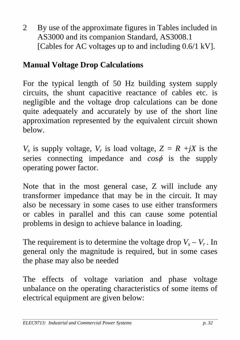
2 By use of the approximate figures in Tables included in AS3000 and its companion Standard, AS3008.1 [Cables for AC voltages up to and including 0.6/1 kV].
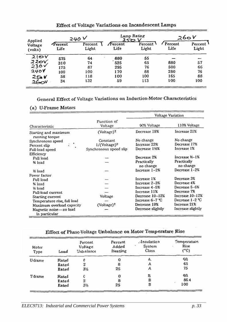
Manual Voltage Drop Calculations For the typical length of 50 Hz building system supply circuits, the shunt capacitive reactance of cables etc. is negligible and the voltage drop calculations can be done quite adequately and accurately by use of the short line approximation represented by the equivalent circuit shown below. Vs is supply voltage, Vr is load voltage, Z = R +jX is the series connecting impedance and cosφ is the supply operating power factor. Note that in the most general case, Z will include any transformer impedance that may be in the circuit. It may also be necessary in some cases to use either transformers or cables in parallel and this can cause some potential problems in design to achieve balance in loading. The requirement is to determine the voltage drop Vs – Vr . In general only the magnitude is required, but in some cases the phase may also be needed The effects of voltage variation and phase voltage unbalance on the operating characteristics of some items of electrical equipment are given below:
ELEC9713: Industrial and Commercial Power Systems p. 32
ELEC9713: Industrial and Commercial Power Systems p. 33
ELEC9713: Industrial and Commercial Power Systems p. 34
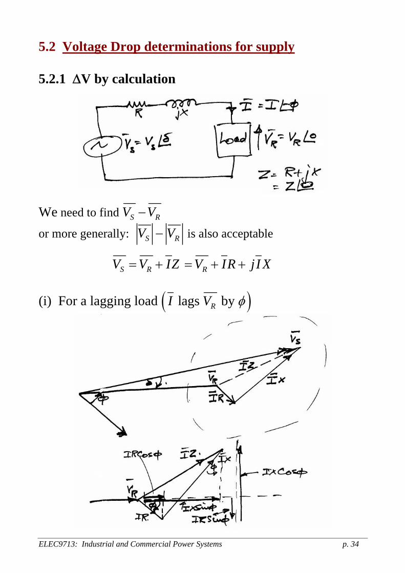
5.2 Voltage Drop determinations for supply 5.2.1 ΔV by calculation
We need to find S RV V−
or more generally: S RV V− is also acceptable
S RV V IZ= + RV IR jI X= + + (i) For a lagging load ( )lags by RI V φ
ELEC9713: Industrial and Commercial Power Systems p. 35
We have: S RV V IR jI X= + + But: 0 and o
R RV V I I φ= ∠ = ∠−
Thus: cos sinS RV V IR IXφ φ= + + ( )cos sinj IX IRφ φ+ − and:
( ) ( )2 2cos sin cos sinS RV V IR IX IX IRφ φ φ= + + + − φ or just using the real part:
cos sinS RV V IR IXφ φ+ + and thus the voltage drop (regulation) is:
cos sinS RV V IR IXφ φ− = + . This formula is quite accurate enough for general use and is used for voltage drop calculations extensively. Note that we require the values of R and X which are constant, and I and φ which can vary. Here φ denotes absolute magnitude of the angle (unsigned). The regulation is load dependent. In many cases, we know VS but not VR, so then have to use:
R SV V I= − Z This is not so easy to solve as the equation:
S RV V I= + Z

(ii) For a leading load ( )leads by RI V φ
Here: cos sinS RV V IR IXφ φ= + − ( )sin cosj IR IXφ φ+ + Again, if we just take the real part:
cos sinS RV V IR IXφ φ− = − [However, it is less accurate now because the imaginary part is higher.] However, in general, we can use:
cos sinS RV V IR IXφ φ− = ± for regulation with + for lagging loads and – for leading loads. Note that the Z R jX= + can represent a transformer impedance and so it can be used to find regulation of transformers.
ELEC9713: Industrial and Commercial Power Systems p. 36

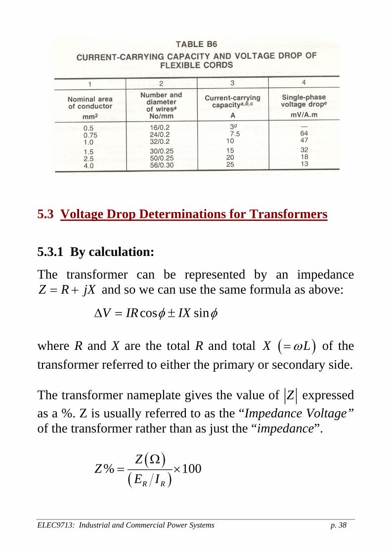
5.2.2 ΔV by using tables (eg Wiring Rules)
ELEC9713: Industrial and Commercial Power Systems p. 37
ELEC9713: Industrial and Commercial Power Systems p. 38
5.3 Voltage Drop Determinations for Transformers
5.3.1 By calculation:
The transformer can be represented by an impedance Z R jX= + and so we can use the same formula as above:
cos sinV IR IXφ φΔ = ± where R and X are the total R and total ( )X Lω= of the transformer referred to either the primary or secondary side. The transformer nameplate gives the value of Z expressed as a %. Z is usually referred to as the “Impedance Voltage” of the transformer rather than as just the “impedance”.
( )( )
% 1R R
ZZ
E IΩ
= × 00
ELEC9713: Industrial and Commercial Power Systems p. 39
where and are rated voltage and current. RE RI ( )Z Ω is determined from the transformer’s short-circuit test when a voltage level Vsc is applied to pass rated current through the transformer windings.
( )SC RV I Z= × Ω As a percent, Z% is the same for the primary and secondary reference: ( ) ( ) ( )Z R jXΩ = Ω + Ω
% % %Z R jX= + (R Ω) ) can be measured with an ohmmeter and can
then be calculated from: (X Ω
( ) ( ) ( )2 2X Z RΩ = Ω − Ω
2 2% % %X Z R= − Typically, when power >200 kVA, X R≈ :
Z is in the range 3-8% ; R is in the range 1-2% 5.3.2 By use of known data for transformers using impedances The following tables give typical values of R, X and Z for transformers of various ratings.

ELEC9713: Industrial and Commercial Power Systems p. 40
ELEC9713: Industrial and Commercial Power Systems p. 41
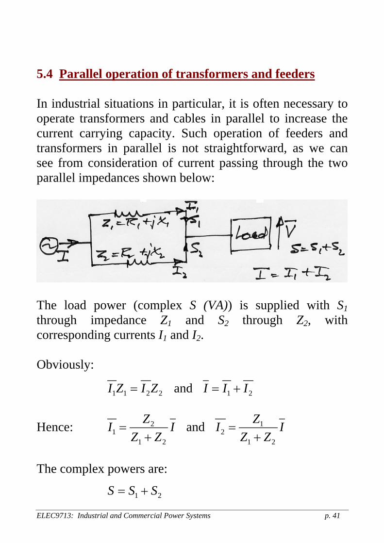
5.4 Parallel operation of transformers and feeders In industrial situations in particular, it is often necessary to operate transformers and cables in parallel to increase the current carrying capacity. Such operation of feeders and transformers in parallel is not straightforward, as we can see from consideration of current passing through the two parallel impedances shown below:
The load power (complex S (VA)) is supplied with S1 through impedance Z1 and S2 through Z2, with corresponding currents I1 and I2. Obviously:
1 1 2 2 1 2 and I Z I Z I I I= = +
Hence: 2 11 2
1 2 1 2
and Z ZI I IZ Z Z Z
= =+ +
I
The complex powers are:
1 2S S S= +

ELEC9713: Industrial and Commercial Power Systems p. 42
* *
1 2V I V I V I*
= ⋅ + ⋅ = ⋅
Thus: * *
* *2 21 1
1 2 1 2
Z ZS V I V IZ Z Z Z
S⎡ ⎤ ⎡ ⎤
= ⋅ = =⎢ ⎥ ⎢ ⎥+ +⎣ ⎦ ⎣ ⎦
Similarly: *
12
1 2
ZS SZ Z⎡ ⎤
= ⎢ ⎥+⎣ ⎦
Also: *
21
1 2
%% %ZS
Z Z⎡ ⎤
= ⎢ +⎣ ⎦S⎥ ; and S2 similarly
[Note that the % values must be referred to the same base values.] Thus, the supplied power divides according to:
* *
1 2 2
2 1 1
%%
S Z ZS Z Z
⎡ ⎤ ⎡ ⎤= =⎢ ⎥ ⎢ ⎥⎣ ⎦ ⎣ ⎦
Thus, parallel lines or transformers divide the total load so that the load in each is in inverse proportion to their impedance. Thus, it is important for transformers to be matched in impedance when they are operated in parallel. If not matched, one may be overloaded when supplying a total power that is the numerical sum of their ratings.

ELEC9713: Industrial and Commercial Power Systems p. 43
The transformer ratings must satisfy the requirement as
deally, Z1 and Z2 should have the same phase angle (so that
stated in the equation above and they should operate at the same overall power factors to get maximum VA ratings. I
2 1Z Z is a real number).
lso, the voltage ratios must be the same. Otherwise,
While this circulating current is a real problem when
Acirculating currents will occur. Even a very small voltage difference can cause substantial current that can increase losses and cause saturation of core material. [supplying real loads, such circulating currents can be used usefully to do dummy full load tests on transformers by using two transformers in a back to back arrangement with a slightly different voltage on each unit (eg by using different taps on the transformer windings). This then causes circulating current to flow and the voltage differential can be adjusted to simulate a real load situation with full load current.]

6. SUBSTATIONS The main substation location on a site should be chosen to be at the electrical load centre if possible, so as to keep feeder cable lengths as short as possible and to keep voltage drop to a minimum and to assist in maintaining voltage regulation as much as possible within the requirements. In very high rise buildings and in extensive factory or similar sites with many buildings, a number of secondary substations may be required to distribute power equitably. Normally these would be connected in a ring main system at high voltage (11 kV) in a large consumer’s site. The supply authority will normally determine the type and size of the substation requirements for a specific situation, but the design, cost, installation and maintenance of the substations are the responsibility of the customer. 6.1 Types of Substations
Pole-mounted substation
The primary component of the substation is an un-enclosed 11,000/415V oil-insulated transformer, rated up to about 500 kVA for providing supply at 415/240V. The substation will also be equipped with associated high voltage fuses of the expulsion or high rupturing capacity (HRC) type, surge arresters or arcing gaps, low voltage HRC fuses and an earthing system (usually just a driven rod in the ground near the pole) for connection of the transformer neutral to the general mass of earth.
ELEC9713: Industrial and Commercial Power Systems p. 44

Pole mounted Tx substation Pad mounted Tx substation
Pad-mounted substation
These are metal enclosed kiosk-type cubicles mounted on the ground. The main component is again an oil-filled transformer of similar or possibly higher rating than for the pole mount type. The kiosk incorporates similar protection and control-gear to the pole-mounted substation. Voltages are also 11,000/415 and the maximum power levels are typically 1000kVA. The pad-mount substation is always connected by cables, no overhead lines. Outdoor (fenced) enclosures
For higher power levels than 1000kVA, an outdoor fenced enclosure may be used. The transformer may be un-enclosed, with appropriate switches, protection and control-gear within the enclosure. The voltages are typically
ELEC9713: Industrial and Commercial Power Systems p. 45
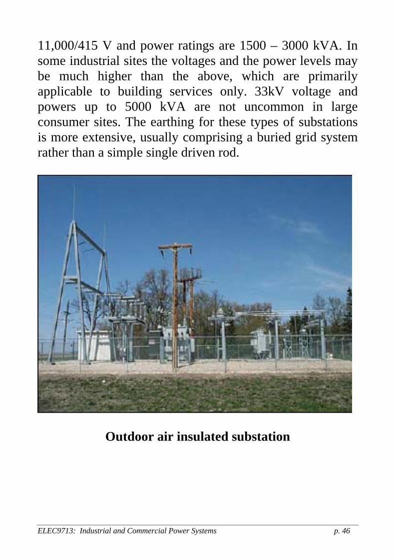
11,000/415 V and power ratings are 1500 – 3000 kVA. In some industrial sites the voltages and the power levels may be much higher than the above, which are primarily applicable to building services only. 33kV voltage and powers up to 5000 kVA are not uncommon in large consumer sites. The earthing for these types of substations is more extensive, usually comprising a buried grid system rather than a simple single driven rod.
Outdoor air insulated substation
ELEC9713: Industrial and Commercial Power Systems p. 46

Outdoor (building) enclosure
This consists of a dedicated small building containing transformers and the other usual items of equipment listed above. Voltages are 11,000/415V and power ratings are up to about 5000 kVA. Outdoor transformer with indoor control-gear
Consists of an open outdoor transformer with a small building for other equipment as outlined above. Voltages are 11000/415 V and power ratings are up to about 5000 kVA. Indoor basement or ground-floor substation
As above, but located indoors. May be SF6 gas insulated systems.
Indoor SF6 gas insulated substation
ELEC9713: Industrial and Commercial Power Systems p. 47

AS/NZS 3000:2007
ELEC9713: Industrial and Commercial Power Systems p. 48
ELEC9713: Industrial and Commercial Power Systems p. 49
ELEC9713: Industrial and Commercial Power Systems p. 50 ELEC9713: Industrial and Commercial Power Systems p. 50
ELEC9713: Industrial and Commercial Power Systems p. 51

ELEC9713: Industrial and Commercial Power Systems p. 52