electrical safety innovation
TRANSCRIPT

Electrical Safety Innovation
How today’s technology is enabling the next-generation of electrical LOTO
Marty Kronz [email protected]

Agenda1. Review Prevention through Design, Hierarchy of
Controls, Electrical Hazards
2. Electrical LOTO Example
3. Voltage Testing Technologies
4. Best practices for evaluating and applying electrical safety technology

Prevention through Design, Hierarchy of Controls & Electrical Hazards
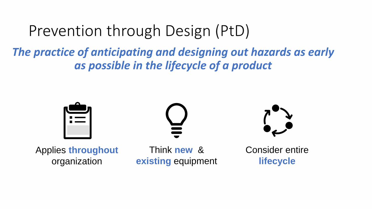
Prevention through Design (PtD)The practice of anticipating and designing out hazards as early
as possible in the lifecycle of a product
Applies throughoutorganization
Think new & existing equipment
Consider entirelifecycle

Hierarchy of Risk Controls
PtD Focus
Elimination
Substitution
Engineering Controls
Administrative Controls
PPE
Most Effective
Least Effective
Physically removethe hazard
Replace the hazard
Isolate people from the hazard
Change the way people work
Protect the worker with Personal Protective Equipment
Administrative Controls
PPE

Lockout Tagout (LOTO)
Control of Hazardous Energy OSHA 29 CFR 1910.147
• Chemical• Electrical• Hydraulic• Mechanical• Pneumatic• Thermal

Electrical Hazards
Fire
Electrical hazards impact everyone – not just electrical workers!
Shock Arc flash
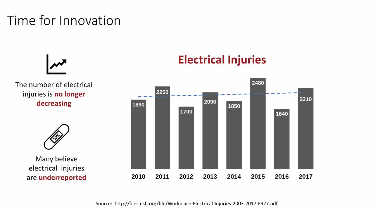
Time for Innovation
Source: http://files.esfi.org/file/Workplace-Electrical-Injuries-2003-2017-F927.pdf
1890
2250
1700
20901850
2480
1640
2210
2010 2011 2012 2013 2014 2015 2016 2017
Electrical Injuries
The number of electrical injuries is no longer
decreasing
Many believe electrical injuries
are underreported

68%
40%
18%
7%
8%
Electrical incident near misses
Electrical incidents
Incidents related to voltage testing
Prefer not to answer
We don't track this information
Frequency of Electrical IncidentsQuestion: Have you experienced any of the following within the past five years?
(n=453)
Source: EHS Today – 2019 Survey

®
10Confidential © 2019 Panduit Corp. All Rights Reserved
Example:Electrical Lockout/Tagout

LOTO…and then Verify!
Isolate Apply Locks/Tags Verify

Verifying a De-Energized Condition
NFPA 70E 120.5 Process for Establishing and Verifying an Electrically Safe Work Condition
(7) Use an adequately rated portable test instrument to test each phase conductor or circuit part to verify it is de-energized. Test each phase conductor or circuit part both phase-to-phase and phase-to-ground. Before and after each test, determine that the test instrument is operating satisfactorily through verification on any known voltage source.
Isolate Energy Source & LOTO

Portable Testers Have LimitationsError Setting Function Selection SwitchElectrician severely burned when a multimeter switch was incorrectly placed in resistance modeprior to making contact with terminals in a 480V MCC.[1]
[1] H. L. Floyd and B. J. Nenninger, “Personnel safety and plant reliability considerations in the selection and use of voltage test instruments,” IEEE Trans. Ind. Appl., vol. 33, no. 2, pp. 367–373, 1997.[2] ”Hispanic factory worker dies of burns after improperly testing a 480-volt electrical bus bar,” Fatality Assessment and Control Evaluation (FACE ) Program, Nat. Inst. Occupational Safety Health, Centers Disease Control Prevention, U.S. Dept. Health Human Services, Cincinnati, OH, 2005.[3] J. Prigmore, J. Bishop and J. Martens, “Electrical Investigations: Case Studies, Common Electrical Safety Mistakes, and Lessons Learned,” IEEE Electrical Safety Workshop, 2018.
Inadequately Rated TesterArc created when a voltmeter was connected across two phases of a bus bar. Arc caused tester to overload and explode resulting in one fatality and another worker with serious burn injuries.[2]
Error Reading Digital Display“OL” or over-range was misinterpreted to mean “zero” or no voltage present, resulting in a near-miss.[1]
Use of Improper Portable TesterAlthough a non-contact voltage probedid not indicate voltage, a lighting circuit was in fact energized, resulting in electrical shock.[3]
Using a Voltmeter for verification has limitations…
• Hardware failures
• Human error
• Process failures
• Misinterpretation
• Exposure to hazards

LOTO and Verification
Traditional process relies on:• Portable testers• Procedures• Training• Personal protective equipment
Elimination
Substitution
Engineering Controls
Administrative Controls
PPE
Administrative Controls
PPE

Administrative Controls
Elimination
Substitution
Engineering Controls
Administrative Controls
PPE
Effective when performed as prescribed
Complexity leads to shortcuts
Normalization of deviance
Experience does not mean fewer errors

Human Factors
Time Pressure
Wor
kloa
d
Multi-tasking
Unc
lear
Re
spon
sibili
ties
Task Demands
Work Environment
Repetitive actionsDistractions
Equipment ConditionPersonality Conflicts
Unexpected Configurations
Interruptions
Skills
Familiarity with Task
Fam
iliar
ity w
ith
Equi
pmen
t
Com
mun
icat
ion
Experience Level
Attit
ude
Fatigue
Illness
Stre
ss
Complacency
Overconfidence
Assumptions
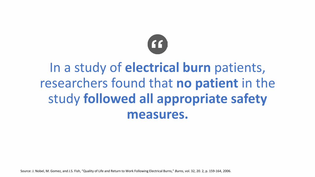
In a study of electrical burn patients, researchers found that no patient in the
study followed all appropriate safety measures.
Source: J. Nobel, M. Gomez, and J.S. Fish, “Quality of Life and Return to Work Following Electrical Burns,” Burns, vol. 32, 20. 2, p. 159-164, 2006.
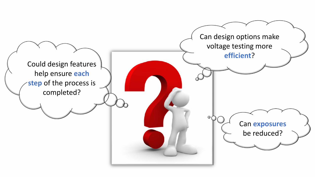
Can design options make voltage testing more
efficient?Could design features
help ensure each step of the process is
completed?
Can exposuresbe reduced?

Applying Prevention through Design
Use of an installed testerReduces likelihood of exposure and severity of exposure Reduces errors from inadequately rated testers
Automating the test processImproves consistency of the verification processReduces human errorsImproves efficiency

Verifying a De-Energized Condition
(7) Use an adequately rated portable test instrument to test each phase conductor or circuit part to test for the absence of voltage. Test each phase conductor or circuit part both phase-to-phase and phase-to-ground. Before and after each test, determine that the test instrument is operating satisfactorily through verification on any known voltage source.
Exception No. 1 to (7): An adequately rated permanently mounted absence of voltage tester shall be permitted to be used to test for the absence of voltage of the conductors or circuit parts at the work location, provided it meets the all following requirements:
1) It is permanently mounted and installed in accordance with the manufacturer’s instructions and tests the conductors and circuit parts at the point of work
2) It is listed and labeled for the purpose of verifying the absence of voltage3) It tests each phase conductor or circuit part both phase-to-phase and phase-to-ground4) The test device is verified as operating satisfactorily on any known voltage source
before and after testing for the absence of voltageInformational Note No. 2. For additional information on rating and design requirements for permanently mounted absence of voltage testers, refer to UL 1436, Outlet Circuit Testers and Other Similar Indicating Devices.
NFPA 70E-2021 120.5 Process for Establishing and Verifying an Electrically Safe Work Condition
CSA Z462-2021 4.2.5 g) Exception 2) & Note 1
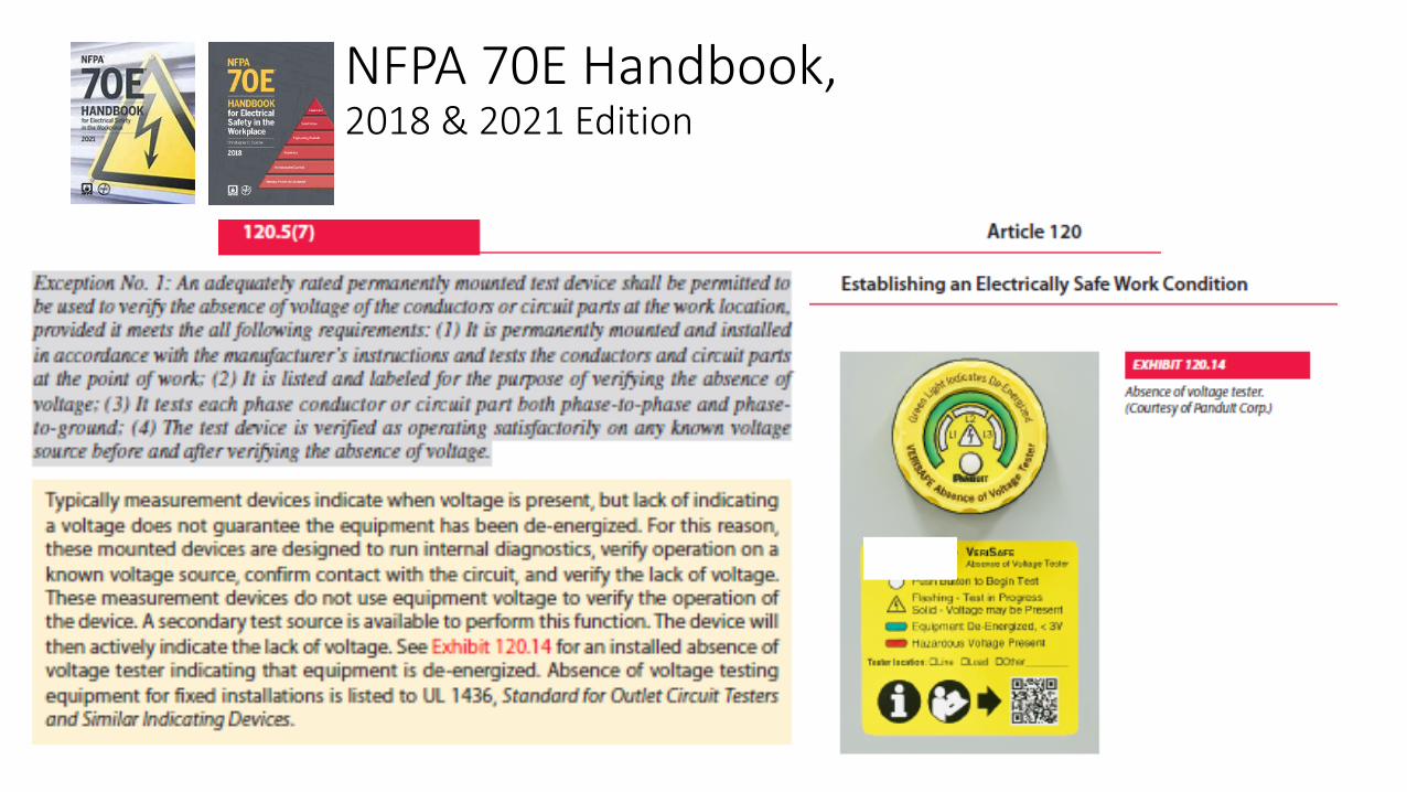
NFPA 70E Handbook, 2018 & 2021 Edition

Comparison of Test MethodsPortable Testers
Absence of Voltage Testers
Activate the VeriSafe™ Absence of Voltage Tester
IndicateResult
Test the Tester
Verify Installation
Check for Voltage
Re-Verify Installation
Re-test the Tester
Manual ProcessPossible Exposure to Electrical Hazards
On average takes 10-20 minutes to complete
Automatically Performed in SequenceNo Exposure to Electrical Hazards
Takes less than 10 seconds to complete

Permanently-Mounted Absence of Voltage Tester
Test before doors are open
Keep hazardous voltage away from door
Hardwired connections to each phase and ground

Traditional Method with Portable Tester
Using a Permanently-Mounted Absence of Voltage Tester (AVT)

VeriSafe™ Absence of Voltage Tester Combines Voltage Presence Indication with Absence of Voltage Testing
Red LEDs indicate hazardous voltage
present
Lack of red LEDs does not guarantee voltage
absence
Push to initiate test and see progress
Green indicates absence of voltage is confirmed

UL 1436
AVT Listing & Labeling Requirements

Active indicationInstallation test & “test the tester”
Keep Hazardous voltage off the door
Test for AC and DC voltage
Key AVT Requirements
User initiated test
Electrical requirements in UL 61010
Functional safety requirements
UL 1436 Standard for Outlet Circuit Testers and Similar Indicating Devices, 6th Edition (September 6, 2016)https://standardscatalog.ul.com/standards/en/standard_1436
Internal overcurrent protection

Electrical Construction• IEC 61010 Provides general safety requirements
for electrical and test measurement equipment• Protection from electrical shock• Electrical spacing and insulation requirements• Impulse and transients• Mechanical impact• Environmental hazards
• Electrical construction requirements are based on combination of Overvoltage Category and Working Voltage
• CAT IV 1000V – 12 kV impulse CAT IV 600V – 8 kV impulse CAT IV 300V –6 kV impulse
• CAT III 1000V – 8 kV impulse CAT III 600V – 6 kV impulse CAT III 300V –4 kV impulse

• Any part of the AVT safety function must meet SIL 3 requirements• The VeriSafe AVT exceeds SIL 3
• Hazardous failure rate (λDU) of 10 • Probability Failure per Hour (PFH) of 10-8
10-8 equates to 1 failure per:
100 million operating hours11,000+ years36 billion tests
Functional Safety and VeriSafe AVTs

Use Cases

Access Control
Reduce workplace hazards through design
Provides an added layer of protection

Next-Generation of Electrical LOTO
Traditional Process
Automated System
• Reduced exposure to hazards• Fewer opportunities for human error• Improved efficiency
Elimination
Substitution
Engineering Controls
Administrative Controls
PPE

Absence of Voltage Testers & Lockout/Tagout
Test for de-energization of the Engel injection mold machine using the VeriSafe AVT. Green light indicates circuit is de-energized. Hydraulic pressure at Gages should go to 0. Attempt to start or operate the equipment.

Control Panels, Motor Control Centers, Safety Switches, Switchgear, Switchboards, Transformers, Packaged Drives, Bus Duct, etc.
Equipment with AVTs
SWITCHBOARDMOTOR CONTROL CENTER (MCC)CONTROL PANEL
AVTs are solutions for New equipment Retrofits OEM installations

Comparing Voltage Testing Technologies
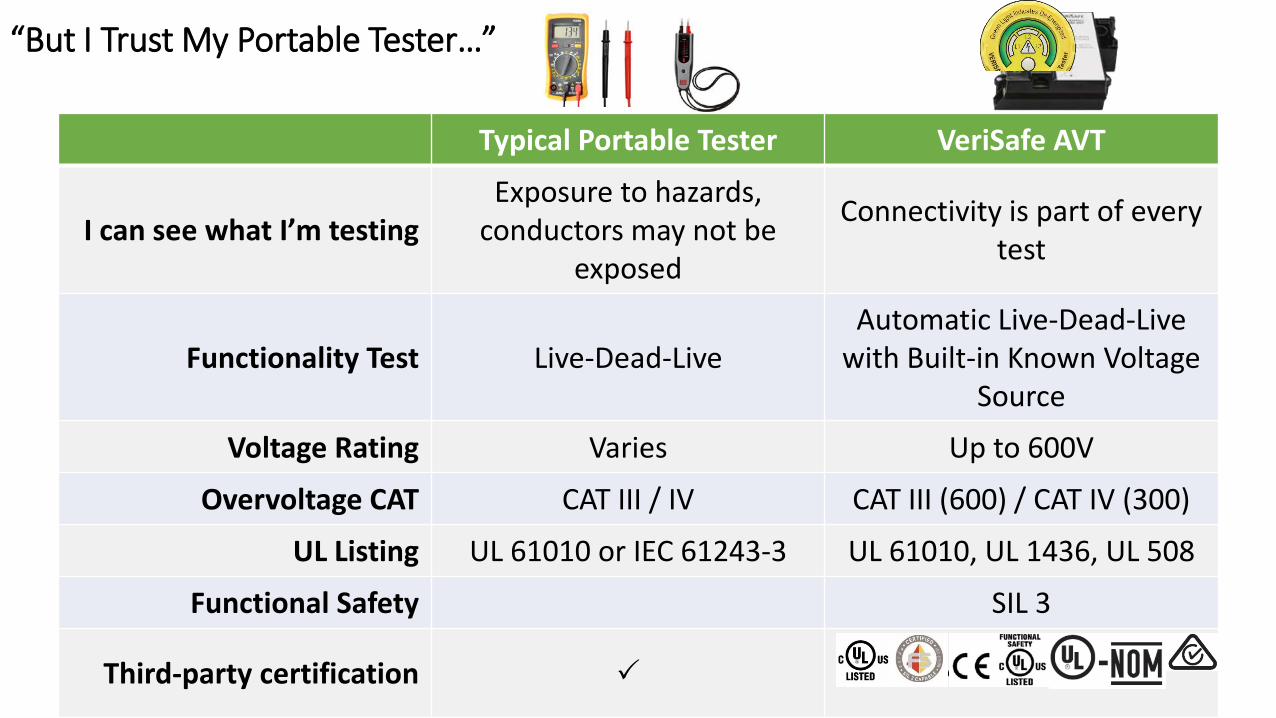
“But I Trust My Portable Tester…”
Typical Portable Tester VeriSafe AVT
I can see what I’m testingExposure to hazards,
conductors may not be exposed
Connectivity is part of every test
Functionality Test Live-Dead-LiveAutomatic Live-Dead-Live
with Built-in Known Voltage Source
Voltage Rating Varies Up to 600V
Overvoltage CAT CAT III / IV CAT III (600) / CAT IV (300)
UL Listing UL 61010 or IEC 61243-3 UL 61010, UL 1436, UL 508
Functional Safety SIL 3
Third-party certification UL / CSA / CE / Exida / NOM / C-tick

Portable Testers Have Risk
Inadequate ratings
Lack of contact with conductors or
ground
Damaged orimproperly
installed probes
Misinterpretation of Settings or Readings
Access to a known voltage source
Exposure to Hazards
Human Error

Voltage Testing Traps
AVT Sensor Leads
Insulated Conductors Barriers
Obstructed Access/Poor Visibility
1
2
3
Finding a Reliable Ground
Fuses & Accessories

Permanently Mounted ProductsAbsence of Voltage Tester (AVT) Voltage Indicator Voltage Portals Analog or Digital
Panel Meter
UL 1436 / IEC/UL 61010 UL/IEC 61010 UL/IEC 61010 IEC/UL 61010
Portable Test InstrumentsDigital Multimeter Voltage Detector Voltage Presence Indicator / Voltage Detector
UL/IEC 61010 IEC 61243-3 UL 1436 / UL/IEC 61010
Terminology Matters

Importance of the Installation Test
Voltage Indicator
Test Portal
Absence of Voltage Tester
How do you verifyinstallation?

Best Practices evaluating and applying electrical safety technology

Qualified electrical worker with ID
credentials
Permanently-mounted AVT Access control at
the enclosure
Training records
Voltage test results logged for auditing
Future VisionA connected infrastructure…designed for safety.

Summary• To advance electrical safety, embrace the continuous improvement
mindset• Leverage the near miss
• Use Prevention through Design when mitigating hazards• Control measures that are designed in are more effective than
administrative controls and PPE alone• Seek out new technology and innovation
• New solutions to old problems like LOTO and verification are now viable

How can you apply PREVENTION THROUGH DESIGN
at your organization?