electrical safety in biophysical measurements
TRANSCRIPT


Not only hospital patients, but also all visitors and
staff must be protected from macro-shocks.
Prevention is required for:
Patients with reduced skin resistance.
Invasive connections.
Exposure to wet conditions.

Grounding system: a tool or electrical system creating a low-resistance path that connects to the earth.
This prevents the buildup of voltages that could cause an electrical accident.
Has a patient-equipment grounding point, reference points and connections.


Isolation from both conductors from ground is commonly achieved with an isolation transformer.
A continually operating line-isolation monitor is used with isolation transformers.
Used to prevent sparks from contact with flammable anesthetics.

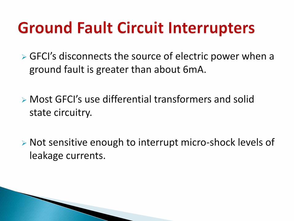
GFCI’s disconnects the source of electric power when a ground fault is greater than about 6mA.
Most GFCI’s use differential transformers and solid state circuitry.
Not sensitive enough to interrupt micro-shock levels of leakage currents.


Leakage current is the current that flows through the protective ground conductor to ground.
CAUSES : DC leakage current applicable only to end-product equipment, not to power supplies. AC leakage current is caused by a parallel combination of capacitance and dc resistance between a voltage source (ac line) and the grounded conductive parts of the equipment.
It can be reduced by using layouts and insulating materials to minimize the capacitance.

CLASS I EQUIPMENT: Protection against electric shock is achieved with the combination of basic insulation and protective earth ground connect to case.
CLASS II EQUIPMENT: The protection against electric shock relies on double insulation or reinforced insulation.
CLASS III EQUIPMENT: Protection relies upon supply source from SELV circuits and in which hazardous voltages are not generated.

Two layers of insulation is employed.
Primary insulation- isolates energized conductor and chassis.
Secondary insulation- isolates chassis from the outer case.
It also helps in reducing leakage current.

Isolation Amplifiers: devices that break ohmiccontinuity of electric signals between input and output.
It usually consists of an instrumentation amplifier input stage followed by a unity gain isolation stage.

Best way to minimize the hazards of micro-shock is to isolate or eliminate electric connections o the heart.
Fully insulated connectors for external cardiac pacemakers powered by batteries help in reducing hazard.

An Electrical safety analyzer is a device dedicated to a various range of electrical safety tests in order to check that the device under test is in compliance with electrical safety requirements.
The typical tests an electrical safety analyzer does are : - ground continuity test - insulation test - high voltage test- line leakage test

When we test system of electric distribution and line powered equipment, we must consider the safety of both the patients and the personnel conducting the test.

Receptacles should be tested for proper wiring , adequate line voltage , low resistance , and mechanical tension
The common three light receptacle testers are deficient in several respect
These device were designed to check only the wiring , but even so they can indicate only 8(2^3) of 64(4^3) possible states for an outlet.

The NFPA 99 requires both voltage and impedance measurements with different limits for new and existing construction
The voltage between a reference grounding point and exposed conductive surface should not exceed 20 mvfor new construction
For existing construction , the limit printed with permission from NEPA 99-1996 .


Isolated power system should have equipotentialgrounding that is similar to the un isolated system
The line isolation monitor should trigger a visible (red) and audible alarms when the total hazard current reaches a threshold of 5mA under a normal line voltage conditions
The LIM should not trigger the alarm for a fault hazard current of less than 3.7mA.

GROUND PIN TO CHASSIS RESISTANCE
The resistance between the ground pin of the plug and the equipment chassis and exposed metal objects should not exceed 0.15ohms during the life of the appliance
During the measurement of resistance , the power cord must be flexed at its connection to the attachment plug and its strain relief where it enters the appliance.

Adequate electrical safety in health-care facilities achieved at moderate cost by combining a good power – distribution system, careful section of well designed equipment , periodic testing of power system and equipment, and a modest training program for medical personnel .