electrical power transmission and distribution ... · 7.3 erection of poles and structures ......
TRANSCRIPT

Draf
t Ken
ya S
tand
ard
for B
allot
ing —
Not
to b
e Ci
ted
as K
enya
Sta
ndar
d
KENYA STANDARD KS 1878-2-3:2010 ICS 20.060.20; 29.240.01
© KEBS 2010 First Edition 2010
Electrical power transmission and distribution — Guidelines for the provision of electrical distribution networks in residential areas — Part 2-3: Preferred methods and materials for the installation of overhead power lines
BALLOT DRAFT, MAY 2010

Draf
t Ken
ya S
tand
ard
for B
allot
ing —
Not
to b
e Ci
ted
as K
enya
Sta
ndar
d
KS 1878-2-3:2010
ii © KEBS 2010 — All rights reserved
TECHNICAL COMMITTEE REPRESENTATION The following organizations were represented on the Technical Committee: Nairobi City Council, City Engineer’s Department. Jomo Kenyatta University of Agriculture and Technology Kenya Polytechnic Kenya Power & Lighting Company Fluid & Power Systems Ltd Ministry of Public Works and Housing Ministry of Energy Kenafric Industries Ltd Power Technics Ltd Rural Electrification Authority The Energy Regulatory Commission Consumer Information Network Kenya Association of Manufacturers Institute of Engineers of Kenya Kenya Electricity Generating Company Ltd ABB LTD Switchgear & Controls Ltd Power Controls Ltd Communications Communication of Kenya Instrument Ltd Kenya Pipeline Company Ltd Telkom Kenya Ltd Meteorological Department Kenya Bureau of Standards — Secretariat
REVISION OF KENYA STANDARDS In order to keep abreast of progress in industry, Kenya standards shall be regularly reviewed. Suggestions for improvement to published standards, addressed to the Managing Director, Kenya Bureau of Standards, are welcome.
© Kenya Bureau of Standards, 2010 Copyright. Users are reminded that by virtue of Section 25 of the Copyright Act, Cap. 12 of 2001 of the Laws of Kenya, copyright subsists in all Kenya Standards and except as provided under Section 26 of this Act, no Kenya Standard produced by Kenya Bureau of Standards may be reproduced, stored in a retrieval system in any form or transmitted by any means without prior permission in writing from the Managing Director.

Draf
t Ken
ya S
tand
ard
for B
allot
ing —
Not
to b
e Ci
ted
as K
enya
Sta
ndar
d
KENYA STANDARD KS 1878-2-3:2010 ICS 20.060.20; 29.240.01
© KEBS 2010 — All rights reserved iii
Electrical power transmission and distribution — Guidelines for the provision of electrical distribution networks in residential areas — Part 2-3: Preferred methods and materials for the installation of overhead power lines
KENYA BUREAU OF STANDARDS (KEBS)
Head Office: P.O. Box 54974, Nairobi-00200, Tel.: (+254 020) 605490, 69028000, 602350, Mobile: 0722202137/8, 0734600471/2;
Fax: (+254 020) 604031 E-Mail: [email protected], Web:http://www.kebs.org
KEBS Coast Regi on P.O. Box 99376, Mombasa 80100 Tel: (+254 041) 229563, 230939/40 Fax: (+254 041) 229448 E-mail: [email protected]
KEBS Lake Region P.O. Box 2949, Kisumu 40100 Tel: (+254 057) 23549,22396 Fax: (+254 057) 21814 E-mail: [email protected]
KEBS North Rift Region P.O. Box 2138, Nakuru 20100 Tel: (+254 051) 210553, 210555

Draf
t Ken
ya S
tand
ard
for B
allot
ing —
Not
to b
e Ci
ted
as K
enya
Sta
ndar
d
KS 1878-2-3:2010
iv © KEBS 2010 — All rights reserved
F O R E W O R D
This Kenya standard was prepared by the Switchgear and Distribution Equipment in accordance with the procedures of the Bureau and is in compliance with Annex 3 of the WTO/TB Agreement. The preferred materials for medium-voltage overhead lines that use wooden poles are given in KS 1877. Where concrete poles are used, these should comply with EAS 489. The preferred materials for low-voltage and medium-voltage overhead lines in low consumption and moderate consumption areas are given in KS 1878-3. This standard is intended to guide service providers in choosing affordable materials while taking into account safety, reliability, durability and environmental compatibility. In the development of this standard, SANS NRS 034-2-3:1996, Guidelines for the provision of electrical distribution networks in residential areas — Part 2-3: Preferred methods and materials for the installation of overhead power lines, was extensively consulted. Assistance derived from this source is hereby acknowledged. Normative and informative annexes A 'normative' annex is an integral part of a standard, whereas an 'informative' annex is only for information and guidance. Summary of development
This Kenya Standard, having been prepared by the Communication Equipment Technical Committee was first approved by the National Standards Council in June 2010
Amendments issued since publication
Amd. No. Date Text affected

Draf
t Ken
ya S
tand
ard
for B
allot
ing —
Not
to b
e Ci
ted
as K
enya
Sta
ndar
d
KS 1878-2-3:2010
© KEBS 2010 — All rights reserved v
Contents
1 Scope .................................................................................................................................................... 1
2 Normative references ........................................................................................................................... 1
3 Abbreviation .......................................................................................................................................... 1
4 Preferred materials ............................................................................................................................... 2
5 Pre-installation activities ....................................................................................................................... 2
5.1 Planning ................................................................................................................................................ 2
5.2 Safety precautions ................................................................................................................................ 2
5.3 Site clearance ....................................................................................................................................... 2
6 Materials delivery, handling, storage and assembly ............................................................................. 3
6.1 General guidelines ................................................................................................................................ 3
6.2 Delivery and handling of material ......................................................................................................... 3
6.3 Storage of poles and cross-arms .......................................................................................................... 4
6.4 Storage of conductors and fittings ........................................................................................................ 4
6.5 Assembly and dressing of poles ........................................................................................................... 5
7 Installation of poles and stays .............................................................................................................. 5
7.1 General ................................................................................................................................................. 5
7.2 Excavation of holes for poles ................................................................................................................ 5
7.3 Erection of poles and structures ........................................................................................................... 6
7.4 Additional structural requirements during erection ............................................................................... 7
7.5 Backfilling .............................................................................................................................................. 7
7.6 Stay installation ..................................................................................................................................... 7
7.7 Installation of pole baulks ..................................................................................................................... 8
7.8 Soil classification (if applicable) ............................................................................................................ 8
8 Installation of conductors .................................................................................................................... 10
8.1 Running out of conductors .................................................................................................................. 10
8.2 Regulating/tensioning ......................................................................................................................... 10
9 Earthing of poles and pole-mounted equipment ................................................................................. 10

Draf
t Ken
ya S
tand
ard
for B
allot
ing —
Not
to b
e Ci
ted
as K
enya
Sta
ndar
d

Draf
t Ken
ya S
tand
ard
for B
allot
ing —
Not
to b
e Ci
ted
as K
enya
Sta
ndar
d
KENYA STANDARD KS 1878-2-3:2010
© KEBS 2010 — All rights reserved 1
Electrical power transmission and distribution — Gu idelines for the provision of electrical distribution networks in re sidential areas — Part 2-3: Preferred methods and materials for the instal lation of overhead power lines 1 Scope This section of KS 1878-2 covers preferred methods and materials used for the installation of low-voltage and medium-voltage overhead power lines in residential areas, and should be read in conjunction with KS 1877, which is referred to extensively. 2 Normative references The following referenced documents are indispensable for the application of this Kenya Standard. For dated references, only the edition cited applies. For undated references, the latest edition of the referenced document (including any amendments) applies. Environmental Management Coordination Act (EMCA), 1998 Occupational Health and Safety Act, 2007 KS 1883, Electrical power transmission and distribution — Overhead power lines — Installation of line conductors KS 503-2, Code of practice for the protection of structures against lightning — Part 2: Code of practice for earthing IEC 61557-1:2007, Electrical safety in low voltage distribution systems up to 1 000 V a.c. and 1 500 V d.c. — Equipment for testing, measuring or monitoring of protective measures — Part 1: General requirements IEC 61557-4:2007, Electrical safety in low voltage distribution systems up to 1 000 V a.c. and 1 500 V d.c. — Equipment for testing, measuring or monitoring of protective measures — Part 4: Resistance of earth connection and equipotential bonding IEC 61557-5:2007, Electrical safety in low voltage distribution systems up to 1 000 V a.c. and 1 500 V d.c. — Equipment for testing, measuring or monitoring of protective measures — Part 5: Resistance to earth KS 1878-3, Electricity distribution — Guidelines for the provision of electrical distribution networks in residential areas — Part 3: Overhead distribution in low and moderate consumption areas. EAS 489, Concrete poles for telephone, power and lighting purposes — Specification KS 1876-1, Electrical power transmission and distribution — Overhead power lines for conditions prevailing in Kenya — Part 1: Code of practice KS 1876-2, Electrical power transmission and distribution — Overhead power lines for conditions prevailing in Kenya — Part 2: Safety KS 1877, Electricity distribution — Guidelines for the application design, planning and construction of medium voltage overhead power lines up to and including 22 kV, using wooden pole structures and bare conductors 3 Abbreviation OHS Act, 2007, The Occupational Health and Safety Act, 2007

Draf
t Ken
ya S
tand
ard
for B
allot
ing —
Not
to b
e Ci
ted
as K
enya
Sta
ndar
d
KS 1878-2-3:2010
2 © KEBS 2010 — All rights reserved
4 Preferred materials The preferred materials for medium-voltage overhead lines that use wooden poles are given in KS 1877. Where concrete poles are used, these should comply with EAS 489. The preferred materials for low-voltage and medium-voltage overhead lines in low consumption and moderate consumption areas are given in KS 1878-3. 5 Pre-installation activities 5.1 Planning NOTE It is assumed that a survey will have been completed and route spanning plans prepared, where applicable (see 5.2.1 of KS 1877). 5.1.1 An experienced person shall be appointed as a construction supervisor in charge of construction work. 5.1.2 In addition to the general duties relating to the construction of overhead lines, as set out in 5.2.4 of KS 1877, the construction supervisor should: a) carry out field inspection of the overhead line route to verify the type of structures required, taking into
account topographical aspects and the crossing of other services, and local conditions; b) ensure that all wayleave agreements and approvals are available (see 5.2.1.3 and 5.2.1.4 of KS 1877); c) ensure that all relevant construction drawings are available for field personnel, and that field personnel
are familiar with the conductor, components and structures to be used; d) provide the relevant regional authorities, in writing, with the required information regarding the
construction work; and e) where practicable, carry out joint planning with providers of other services and relevant authorities,
taking into account possibility for the joint use of poles with telecommunications providers and regarding procedures to be adopted prior to the construction of power lines.
5.2 Safety precautions 5.2.1 The General Safety Regulations of the OHS Act are applicable to personnel, safety equipment and facilities. 5.2.2 Where road crossings are involved, the national, provincial or local authority regulations are applicable. 5.2.3 In areas where the existing reticulation is being extended, those poles that carry live conductors and that could pose a safety hazard to construction personnel, should be marked as "live". Construction personnel should be made aware of the potential safety hazard. 5.2.4 In the case of lines under construction, safety earthing shall be provided against induced lightning surges and against induced power frequency voltages for lines that are near, or parallel to, existing live power lines. 5.3 Site clearance 5.3.1 The clearance of the route to enable construction work to start should be carried out in accordance with applicable environmental regulations. In particular, prior written approval for site clearance shall have been obtained from the Environmental Management Authority and the Kenya Wildlife Services. 5.3.2 Where practicable, vegetation should be so cleared that it does not encroach within a radius of 4 m of any line conductor. 5.3.3 In cases where mechanical excavating equipment is being used (which is preferred) and poles are being erected by vehicle mounted cranes, temporary access routes to various pole positions might be

Draf
t Ken
ya S
tand
ard
for B
allot
ing —
Not
to b
e Ci
ted
as K
enya
Sta
ndar
d
KS 1878-2-3:2010
© KEBS 2010 — All rights reserved 3
required. In such cases, care should be exercised regarding landscape preservation and the conservation of flora. 5.3.4 Where applicable, for example where the line route traverses private property or where mid-boundary reticulation is being provided, land owners should be notified of the intended date of construction, and prior agreement should be obtained if site clearing or tree cutting is required. 5.3.5 In cases where trees have had to be felled or lopped, the timber should be cut to reasonable lengths and neatly stacked or removed in accordance with the land owner's instructions or in accordance with the wayleave agreement, where applicable. 6 Materials delivery, handling, storage and assembl y 6.1 General guidelines Equipment and accessories used for the handling of materials shall be maintained in a safe working condition and this should be ensured by regular inspections. 6.2 Delivery and handling of material 6.2.1 Poles Once the line has been pegged (see KS 1877), the delivery of poles can start. The delivery of the poles can proceed in parallel with the excavating activity. The planting of the poles should immediately follow the excavation of the holes. Care should be exercised in the loading and off-loading of poles. Concrete poles may only be lifted at the designated lifting positions, using lifting gear that will not damage the surface of the pole. Padding should be used under the holding down chains, to protect poles during transportation. Poles should never be thrown off the vehicle because this could cause hidden damage which could lead to failure in service. Off-loading ramps should be used for the manual handling of all poles. The use of cranes for the handling of concrete poles is recommended. Poles should not be dragged along on their butt ends. The delivery of the poles should be properly planned, to ensure that poles of the correct length and correct strength (diameter) are delivered to each peg position. The way in which poles are laid out upon delivery is dependent on the methods of excavation, dressing and erection. If holes are to be manually excavated and the poles erected manually, the pole should be laid out in line with the longitudinal axis of the excavation, with the butt end ready to enter the lead into the hole (see Figure C.22 of KS 1877). If poles are to be erected by crane, as is usually the case for concrete poles, the pole should be laid out sufficiently clear of the peg to allow for crane access, but no further from the peg than is necessary. 6.2.2 Stay assemblies Stay assemblies and other pole hardware required to dress the structures should be delivered at the same time as the poles, provided that there is no risk of theft. 6.2.3 Conductors As considerable activity occurs around a drum site, care should be taken in the selection of the site position, in order to avoid unnecessary damage to valuable land. The importance of this site position increases in the case of longer lines; in the case of short lines, delivery may be combined with the running out of conductors.

Draf
t Ken
ya S
tand
ard
for B
allot
ing —
Not
to b
e Ci
ted
as K
enya
Sta
ndar
d
KS 1878-2-3:2010
4 © KEBS 2010 — All rights reserved
6.3 Storage of poles and cross-arms 6.3.1 Wooden poles and cross-arms Wooden poles and cross-arms will generally only give the projected service life if a long period of storage before installation is avoided. Wooden poles and cross-arms should be allowed adequate time to attain the equilibrium moisture of the area where they are to be used. Wooden poles should be cross-stacked at least 300 mm above the ground and for a maximum period of six months. If they have to be stacked for longer, they should be close-stacked, under cover, in a north-south direction, and, after six months, rotated 180°. The area underneath the stack should be clear of grass and debris, to reduce the risk of fire. Handling equipment should be used in such a way that the surface of the pole or cross-arm is not damaged. Damaged poles and cross-arms should not be used, since their service life will be reduced. 6.3.2 Concrete poles Concrete poles should be stacked on firm, level supports with adequate clearance to allow for any settlement of the bottom bearers. Wooden bearers are preferred. Rectangular concrete poles should be stacked with the narrow faces up. The stacked poles should be separated by wooden bearers placed in a vertical line. Figure 1 and table 1 indicate the recommended support positions for the wooden bearers for concrete pole stacks. As poles have pronounced tapered profiles, the orientation of the succeeding layers should be alternated, a top end being positioned above a butt end (see Figure 1). Only those poles that are of the same length should be stacked together and, in the case of concrete poles, not more than four layers should be stacked.
Figure 1 — Stacking of concrete poles
Table 1 — Dimensions relating to Figure 1
1 2 3 4 5 Pole length/ strength Overhang (A)
mm Butt length (B)
mm Stack centres (C)
mm Tip overhang (D)
mm 9 m / 4 kN 1070 1500 4930 2570 9m / 7kN 1010 1500 4990 2510
9.3m / 17.5kN 500 1800 5200 2300 10m / 8kN 650 1800 5750 2450 11 m / 8 kN 1225 1800 6175 3025
6.4 Storage of conductors and fittings All conductors and fittings should be stored in an appropriate way that both minimizes the potential for damage to these items, and takes the safety of personnel into consideration. Storage areas should be secure; in particular, the value of the conductor at the drum site(s) should be taken into consideration. In

Draf
t Ken
ya S
tand
ard
for B
allot
ing —
Not
to b
e Ci
ted
as K
enya
Sta
ndar
d
KS 1878-2-3:2010
© KEBS 2010 — All rights reserved 5
cases where delays to the line construction might occur, appropriate measures should be taken to prevent the conductor from being stolen. 6.5 Assembly and dressing of poles The dressing of poles should precede their erection. Any holes that have been drilled in wooden poles on site should be treated by being painted with the same type of preservative that was used for the pole itself (for example, creosote). Unused holes in wooden poles should be plugged. When a pole is being dressed, care should be taken to ensure that the dressed structure presents a neat appearance. The stay assembly should be assembled in accordance with figure C.25 of Annex C of KS 1877. Stay wire lengths are determined on site. Allowance for sloping ground is made on site. In cases where stay wires cannot be made off immediately, the stay wires should be tied to the pole at a position above normal reach, to prevent injury to persons and livestock. 7 Installation of poles and stays 7.1 General NOTE Excavation is preferably carried out after the dressed structures are in position and ready for erection, since excavations present a hazard to persons and livestock. 7.1.1 The contractor should install additional pegs in relation to the pole peg and the line (direction) peg(s) to define the pole peg position adequately before excavation is started. 7.1.2 In cases where mechanical equipment that could cause a noise level exceeding 85 dB(A) has to be used to excavate in built-up areas, the requirements of EMCA, 1998, are applicable. 7.1.3 Should blasting be necessary, precautions shall be taken to protect the works, persons, animals and property in the vicinity of the site. 7.1.4 The requirements of the OHS Act are applicable in respect of the depth of excavation in which a person may work without the excavation's being shored. NOTE The step method of excavation in Figure C.22A of KS 1877 complies with the OHS Act. 7.1.5 Overhead and underground services should be protected from inadvertent damage. 7.2 Excavation of holes for poles 7.2.1 The use of mechanical pole hole boring equipment has the advantage that it results in very little disturbance of the natural compacted soil. In cases where excavation is undertaken by hand, as little as possible of the surrounding ground should be disturbed. 7.2.2 General information on the types and design of foundations for poles is given in KS 1886. Pole foundation arrangements are shown in Figure C.22 of KS 1877. Foundations for stays are shown in Figure C.23 of KS 1877. A recommended type of pole hole excavation and the recommended dimensions of excavation for preferred sizes of poles are given in Figure 2 and Table 2 of these guidelines.

Draf
t Ken
ya S
tand
ard
for B
allot
ing —
Not
to b
e Ci
ted
as K
enya
Sta
ndar
d
KS 1878-2-3:2010
6 © KEBS 2010 — All rights reserved
Figure 2 — Recommended type of pole hole excavation
7.2.3 Material that is excavated should be classified and handled in accordance with KS 1889. It is important to separate the excavated soil into top soil and other soil, in order to allow for the reinstatement of the excavation with the top soil in place at ground level. 7.2.4 Preservation and replacement of any survey beacons and pegs are subject to legal provisions.
Table 2 — Dimensions of pole hole excavations
1 2 3 4 5 6 7 8 Type of pole Dimension/ Strength A B C D E F Baulked pole 9 m / 4 kN
9 m / 7 kN 0.6 0.7 0.75 0.7 1.5 1.5
9.3 m / 17.5kN 10 m / 8 kN 0.6 0.7 1.0 0.8 1.5 1.8 11 m / 8 kN Unbaulked pole 9 m / 4 kN 0.6 0.7 0.75 0.6 0.5 1.5 9 m / 7 kN 9.3 m /17.5 kN 10 m / 8 kN 0.6 0.7 1.0 0.7 0.6 1.8 11 m/ 8 kN
7.3 Erection of poles and structures 7.3.1 General
Various methods are available for the erection of poles and this activity should immediately follow the excavation activity (see 6.4 of KS 1877). If unattended, excavations shall be barricaded.

Draf
t Ken
ya S
tand
ard
for B
allot
ing —
Not
to b
e Ci
ted
as K
enya
Sta
ndar
d
KS 1878-2-3:2010
© KEBS 2010 — All rights reserved 7
7.3.2 Mechanical erection Erection by crane requires observance of all safety aspects relating to equipment ratings, equipment stability, and the positioning of personnel. The most suitable method of lifting a concrete pole is to use a steel sling wrapped around the pole, 0.5 m from the centre of gravity towards the top of the pole. Any lintels should by now also have been clamped in position. Chains and fabric slings shall not be used to lift concrete poles, since they can cause localized damage. 7.3.3 Manual erection The equipment needed for the manual erection of steel and wooden poles includes pole pikes (see Figure 1 of KS 1877) for wooden poles, or ladders with reinforced top rungs, or another form of adaptation that consists of a special attachment to engage and support the pole during the raising operation. CAUTION — Under no circumstances should a normal la dder be subjected to the loads imposed by the lifting of poles. The construction supervisor shall ensure that no support is released until the load has been taken up by another support. Stayed poles should be so erected that, upon completion of the backfill operation, the pole is leaning away from the stay position by at least half a pole thickness at the top. This will ensure correct alignment when the stay is made off correctly. 7.4 Additional structural requirements during erect ion Where so required, pole bases, kickplates and lateral blocks should be installed (see Annex C of KS 1877 for drawings of various terminal structures and poles on which equipment is installed). 7.5 Backfilling 7.5.1 Backfilling is an extremely important part of structure erection, and it is essential that it be carried out correctly — for both pole and stay installations. The backfill should be introduced into the excavation in small quantities and thoroughly rammed to ensure maximum compaction and bearing pressure. A layer of backfill not exceeding 200 mm at a time should be rammed as solidly as possible before the next layer is added. To achieve this objective, typically there should be twice as many workmen ramming as shovelling. In the case of an unstayed concrete pole, the pole should be inclined, before backfilling, along the line of the conductors but in the opposite direction to the one in which the conductors will be tensioned. The pole should be inclined by about half a pole thickness at the top, to allow for eventual consolidation of the backfill when the conductors are tensioned. Where the backfill material is such that it will not consolidate, i.e. is non-cohesive, it is necessary to add cement in the ratio of 1 unit of cement to 8 units of soil (a unit could be a shovel full). The soil and cement should be thoroughly mixed before being returned to the excavation as backfill. It is preferable to moisten the soil/cement mix slightly by adding a little water to the mixture. (Not too much water should be added, since the mix will be weakened and will not consolidate when rammed.) The moistened mix should be returned to the excavation in small quantities and should be thoroughly rammed. 7.5.2 Upon completion of backfilling, there should be very little surplus soil, and this should be mounted around the pole and compacted to ensure that water will run off. 7.6 Stay installation Temporary stays may be used if the soil conditions where work is being carried out are unusual, but the stays should be removed when no longer required. The stays should be installed in accordance with Figure C.23 of KS 1877, and should be carefully backfilled. When a stay has been installed, the stay wire should be made off in accordance with Figure C.25 of KS 1877.

Draf
t Ken
ya S
tand
ard
for B
allot
ing —
Not
to b
e Ci
ted
as K
enya
Sta
ndar
d
KS 1878-2-3:2010
8 © KEBS 2010 — All rights reserved
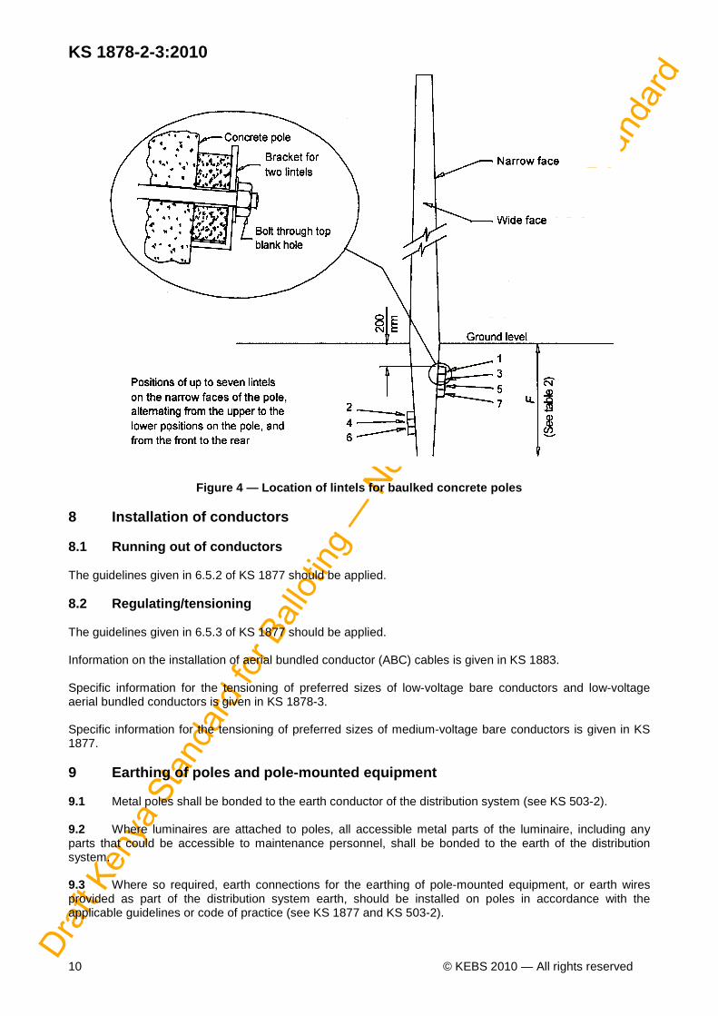
Stayed poles should be so erected that they lean away from the stay before tensioning starts (see 6.4.2 of KS 1877). When the stay wire is tensioned using the correct tensioning equipment such as a pull-lift and come-along clamps, the stay should be tensioned until the pole leans towards the stay by about half a pole thickness at the top. No off-cuts of stay wire should be left on site, because these are dangerous to livestock. 7.7 Installation of pole baulks 7.7.1 General Where poles are installed as unstayed structures (free-standing), and depending on the soil classification (see 7.8), it may be necessary to provide baulks attached near the base of the poles, below ground level. The baulks reduce the bearing pressure and spread the lateral forces over a larger area on the sides of the hole, thereby increasing the stability of the poles. 7.7.2 Baulks for wooden poles Where the soil is non-cohesive and loose, or cohesive and soft, pole baulks should be provided as shown in figure 3. 7.7.3 Baulks for concrete poles The number of lintels to be installed depends on the load on the pole and the soil properties, as shown in Table 4. The dimensions of a lintel are 100 mm × 70 mm × 1 200 mm. The lintels are fastened to the narrow face(s) of the concrete pole, using steel brackets. The lintels are positioned near the top and near the bottom of the hole and on the front and on the rear of the pole and are alternated as indicated in Figure 4. 7.8 Soil classification (if applicable) NOTE The soil classification method should be applied in the case of any unstayed structure where the soil conditions are uncertain. The soil is classified according to its cohesiveness and its consistency (see Table 3). To determine cohesiveness, the soil is wet and an attempt made to knead it into a pat. A cohesive soil can be kneaded into a pat, whereas a non-cohesive soil cannot. A dynamic cone penetrometer (DCP) test and standard apparatus are used to measure the consistency. The consistency of the soil is determined from Table 3, depending on the number of blows needed to drive a standard cone 100 mm into the test soil. The blows are delivered by a hammer of mass 7.315 kg that falls through a height of 575 mm. Carry out three penetrometer measurements during the excavation, one each at three depth levels, i.e. at 25 %, at 50 % and at 75 % of the depth of the excavation. Calculate the average of the number of blows and read off the soil consistency, depending on whether the soil is cohesive or non-cohesive.
Table 3 — Soil consistency according to soil type a nd number of penetrometer blows
1
2
3 Soil type
Consistency
Number of blows Non-cohesive Loose 1 or 2
Medium dense 3 to 10
Dense
11 or more Cohesive Soft 1
Firm 2 to 7
Stiff
8 or more

Draf
t Ken
ya S
tand
ard
for B
allot
ing —
Not
to b
e Ci
ted
as K
enya
Sta
ndar
d
KS 1878-2-3:2010
© KEBS 2010 — All rights reserved 9
Table 4 — Number of lintels required for concrete p oles for soil type and consistency according to pole length and strength
1 2 3 4 5 6 7
Soil type Consistency Number of lintels req uired Pole length/ strength 9m / 4kN 9m / 7kN 9.3m / 17.5kN 10m / 8kN 11 m / 8kN
Non-cohesive Loose 2 3 6 4 5 Medium dense 1 3 7 2 3 Dense 1 2 4 1 2
Cohesive Sort 2 2 5 2 2 Firm 1 2 3 1 2 Stiff 0 0 0 0 0
Figure 3 — Location of baulk on wooden poles Positions of up to seven lintels on the narrow faces of the pole, alternating from the upper to the lower positions on the pole, and from the front to the rear
Draf
t Ken
ya S
tand
ard
for B
allot
ing —
Not
to b
e Ci
ted
as K
enya
Sta
ndar
d
KS 1878-2-3:2010
10 © KEBS 2010 — All rights reserved
Figure 4 — Location of lintels for baulked concrete poles 8 Installation of conductors 8.1 Running out of conductors The guidelines given in 6.5.2 of KS 1877 should be applied. 8.2 Regulating/tensioning The guidelines given in 6.5.3 of KS 1877 should be applied. Information on the installation of aerial bundled conductor (ABC) cables is given in KS 1883. Specific information for the tensioning of preferred sizes of low-voltage bare conductors and low-voltage aerial bundled conductors is given in KS 1878-3. Specific information for the tensioning of preferred sizes of medium-voltage bare conductors is given in KS 1877. 9 Earthing of poles and pole-mounted equipment 9.1 Metal poles shall be bonded to the earth conductor of the distribution system (see KS 503-2). 9.2 Where luminaires are attached to poles, all accessible metal parts of the luminaire, including any parts that could be accessible to maintenance personnel, shall be bonded to the earth of the distribution system. 9.3 Where so required, earth connections for the earthing of pole-mounted equipment, or earth wires provided as part of the distribution system earth, should be installed on poles in accordance with the applicable guidelines or code of practice (see KS 1877 and KS 503-2).