electrical parameter identification of single-phase...
TRANSCRIPT

Chapter 0
Electrical Parameter Identificationof Single-Phase Induction Motorby RLS Algorithm
Rodrigo Padilha Vieira, Rodrigo Zelir Azzolin, Cristiane Cauduro Gastaldiniand Hilton Abílio Gründling
Additional information is available at the end of the chapter
http://dx.doi.org/10.5772/37664
1. Introduction
This chapter addresses the problem of the electrical parameter identification of Single-PhaseInduction Motor (SPIM). The knowledge of correct electrical parameters of SPIM allows abetter representation of dynamic simulation of this machine. In addition, the identifiedparameters can improve the performance of the Field Oriented Control (FOC) and sensorlesstechniques used in these systems.
Controlled induction motor drives have been employed on several appliances in the lastdecades. Commonly, the control schemes are based on the FOC and sensorless techniques.These methods are mainly applied to three-phase induction machine drives, and a widenumber of papers, such as [5, 9, 10, 15, 19, 23, 26] have described such drives. On the otherhand, for several years the SPIM has been used in residential appliances, mainly in low powerand low cost applications such as in freezers and air conditioning, consuming extensive rateof electrical energy generated in the world. In most of these applications, the SPIM operatesat fixed speed and is supplied directly from source grid. However, in the last few yearsseveral works have illustrated that the operation with variable speed can enhance the processefficiency achieved by the SPIM ([1, 4, 8, 31]). Furthermore, some other studies have presentedhigh performance drives for SPIM using vector control and sensorless techniques, such as ispresented in [7, 12, 18, 24] and [29]. However, these schemes applied on single-phase andthree-phase induction motor drives need an accurate knowledge of all electrical parametersmachine to have a good performance.
As a consequence of the parameter variation and uncertainties of the machine, literaturepresents algorithms for computational parameter estimation of induction machines, mainlyabout three-phase induction machines ([3, 13, 20, 21, 27]). Some authors proposed an on-line
©2012 Vieira et al., licensee InTech. This is an open access chapter distributed under the terms of theCreative Commons Attribution License (http://creativecommons.org/licenses/by/3.0),which permitsunrestricted use, distribution, and reproduction in any medium, provided the original work is properlycited.
Chapter 11

2 Will-be-set-by-IN-TECH
parameter estimation, for adaptive systems and self-tuning controllers due to the fact that theparameters of induction machine change with temperature, saturation, and frequency ([22]).
Differently from the three-phase induction motors, the SPIM is an asymmetrical and coupledmachine; these features make the electrical parameter estimation by classical methodsdifficult, and these characteristics complicate the use of high performance techniques, suchas vector and sensorless control. Thus, the use of Recursive Least Square (RLS) algorithmcan be a solution for the parameter estimation or self-tuning and adaptive controllers, such aspresented in [28] and [30]. Other studies have also been reported in literature describing theparameter estimation of SPIM ([2, 11, 17, 25]).
The aim of this chapter is to provide a methodology to identify a set of parameters for anequivalent SPIM model, and to obtain an improved SPIM representation, as consequence it ispossible to design a high performance sensorless SPIM controllers. Here, from the machinemodel, a classical RLS algorithm is applied at q and d axes based on the current measurementsand information of fed voltages with a standstill rotor. The automatized test with standstillrotor can be a good alternative in some applications, such as hermetic compressor systems,where the estimation by conventional methods is a hard task due the fact of the machine issealed.
An equivalent SPIM behavior representation is obtained with this methodology in comparisonwith the SPIM model obtained by classical tests. However, some types of SPIM drives, forinstance a hermetic system, it is impossible to carried out classical tests. In addition, theproposed methodology has a simple implementation.
This chapter is organized as follows: Section 2 presents the SPIM model, Section 3 gives theRLS parameter algorithm, Section 4 presents and discusses the experimental results obtainedwith the proposed methodology, and Section 5 gives the main conclusions of this study.
2. Single-phase induction motor model
The commercial SPIM commonly used in low power applications is usually a two-phaseinduction machine with asymmetrical windings, whose equivalent circuit without thepermanent split-capacitor can be represented as in Fig. 1.
lsqL
mqL
'q
d
N
r rdN� �
lrqL
rqR
sqR
+_
sqVsqi
+
_
lsdL
mdL
'd
q
N
r rqN� �
lrdL
rdR
sdR
+_
sdVsdi
+
_
Figure 1. Equivalent circuit of SPIM.
276 Induction Motors – Modelling and Control

Electrical Parameter Identification of Single-Phase Induction Motorby RLS Algorithm 3
As in [14], in this chapter the squirrel cage SPIM mathematical model is described in astationary reference-frame by the following equations[
Vsq
Vsd
]=
[Rsq 0
0 Rsd
] [isq
isd
]+
ddt
[φsq
φsd
](1)
[Vrq
Vrd
]=
[Rrq 0
0 Rrd
] [irq
ird
]+
ddt
[φrq
φrd
]
+ωr
[0 −1/nn 0
] [φrq
φrd
]=
[0
0
] (2)
[φsq
φsd
]=
[Lsq 0
0 Lsd
] [isq
isd
]+
[Lmq 0
0 Lmd
] [irq
ird
](3)
[φrq
φrd
]=
[Lmq 0
0 Lmd
] [isq
isd
]+
[Lrq 0
0 Lrd
] [irq
ird
](4)
Te = p(Lmqisqird − Lmdisdirq) (5)
p(Te − TL) = Jdωr
dt+ Bnωr (6)
where, the indexes q and d represent the main winding and auxiliary winding, respectively,the indexes sq and sd represent the stator variables, and the indexes rq and rd are used forthe rotor variables. Vsq, Vsd, Vrq, Vrd, isq, isd, irq, ird, φsq, φsd, φrq, and φrd are the stator androtor voltages, currents, and flux; Rsq, Rsd, Rrq, and Rrd are the stator and rotor resistances;Llsq, Llsd, Llrq, and Llrd are the leakage inductances; Lmq and Lmd are the mutual inductances;Lsq, Lsd, Lrq, and Lrd are the stator and rotor inductances, and are given by: Lsq = Llsq + Lmq,Lsd = Llsd + Lmd, Lrq = Llrq + Lmq, and Lrd = Llrd + Lmd; Nq and Nd represent the numberof turns for the main and auxiliary windings, respectively; p is the pole pair number and ωris the rotor speed, and n is the relationship between the number of turns for auxiliary and formain winding Nd/Nq. Te is the electromagnetic torque, TL is the load torque, Bn is the viscousfriction coefficient, and J is the inertia coefficient.
From (1) - (4) it is possible to obtain the differential equations that express the dynamicalbehavior of the SPIM, as follows,
ddt
isq = −RsqLrq
σqisq−ωr
1n
LmqLmd
σqisd +
RrqLmq
σqirq−ωr
1n
LrdLmq
σqird +
Lrq
σqVsq (7)
ddt
isd = ωrnLmdLmq
σdisq− LrdRsd
σdisd + ωrn
LrqLmd
σdirq +
RrdLmdσd
ird +Lrdσd
Vsd (8)
ddt
irq =LmqRsq
σqisq + ωr
1n
LsqLmd
σqisd−
LsqRrq
σqirq + ωr
1n
LsqLrd
σqird−
Lmq
σqVsq (9)
ddt
ird = −ωrnLsdLmq
σdisq +
LmdRsdσd
isd−ωrnLsdLrq
σdirq− LsdRrd
σdird− Lmd
σdVsd (10)
277Electrical Parameter Identifi cation of Single-Phase Induction Motor by RLS Algorithm

4 Will-be-set-by-IN-TECH
where σq = LsqLrq− L2mq, σd = LsdLrd − L2
md.
The transfer functions in the axes q and d at a standstill rotor (ωr = 0) are obtained from(7)-(10), where these functions are decoupled and presented in (11) and (12).
Hq(s) =isq(s)Vsq(s)
=sσ−1
q Lrq + σ−1q τ−1
rq Lrq
s2 + spq + σ−1q RrqRsq
(11)
Hd(s) =isd(s)Vsd(s)
=sσ−1
d Lrd + σ−1d τ−1
rd Lrd
s2 + spd + σ−1d RrdRsd
(12)
where pq =(
RsqLrq + RrqLsq)/
σq and pd = (RsdLrd + RrdLsd)/
σd.
3. Parameter identification of single-phase induction machine
In section 2, the decoupled transfer functions of the SPIM were obtained assuming a standstillrotor (ωr = 0). Thus, in this section the parameter identification is achieved with SPIM at astandstill rotor by a RLS algorithm. The identification with a standstill rotor is appropriated insome cases such as hermetic refrigeration compressors ([28]). The RLS identification algorithmrequires the plant model in a discrete time linear regression form. Assuming the actualsampling index k, the regression model is given by
Y(k) = φT(k)θ(k) (13)
The recursive algorithm is achieved with the equations (14)-(17).
e(k) = Y(k)− Y(k) (14)
K(k) =P(k− 1)φ(k)
1 + φT(k)P(k− 1)φ(k)(15)
θ(k) = θ(k− 1) + K(k)e(k) (16)
P(k) =(
I −K(k)φT(k))
P(k− 1) (17)
where dim Y = M× N, dim φT(k) = M× r
dim θ(k) = r× N, dim e(k) = M× N
dim K(k) = r× M , dim I = dim P(k) = r× r
From the equations (11) and (12) it is possible to reformulate the estimation parameter problembased on a linear regression model. Here, the parameter estimation method is divided intotwo steps:
First step: estimation of (18) and (19) vide equations (20) and (21) :
This step consists into obtaining a linear-time-invariant model of the SPIM. The identificationof b1, b0, a1 and a0 is done by performing a standstill test. The coefficients presented in (11)and (12) are functions of the machine parameters. For simplicity, the transfer functions givenin (11) and (12) are rewritten in two transfer functions given by (18) and (19).
Hq(s) =issq(s)
Vssq(s)
=sb1q + b0q
s2 + sa1q + a0q(18)
278 Induction Motors – Modelling and Control
Electrical Parameter Identification of Single-Phase Induction Motorby RLS Algorithm 5
and
Hd(s) =issd(s)
Vssd(s)
=sb1d + b0d
s2 + sa1d + a0d(19)
where
b1q =Lrq
σq, b0q =
Lrq
σqτrq, a1q =
RsqLrq + RrqLsq
σq, a0q =
RsqRrq
σq(20)
andb1d =
Lrdσd
, b0d =Lrd
σdτrd, a1d =
RsdLrd + RrdLsdσd
, a0d =RsdRrd
σd(21)
In order to obtain the regression linear model the transfer functions of (18) and (19) can be
generalized and rewritten as,
d2isq
dt2 + a1qdisq
dt+ a0qisq = b1q
dVsq
dt+ b0qVsq (22)
andd2isd
dt2 + a1ddisddt
+ a0disd = b1ddVsd
dt+ b0dVsd (23)
Solving for the second derivative of the stator current,
d2isq
dt2 =
[− disq
dt−isq
dVsq
dtVsq
] ⎡⎢⎢⎣a1qa0qb1qb0q
⎤⎥⎥⎦ (24)
and
d2isd
dt2 =
[− disd
dt−isd
dVsddt
Vsd
] ⎡⎢⎢⎣a1da0db1db0d
⎤⎥⎥⎦ (25)
The estimation of coefficients b1q, b0q, a1q, a0q, b1d, b0d, a1d and a0d is done by using RLSestimation algorithm described in the equations (13)-(17). The linear regression model form(13) is given for the q axis by the following equations,
Yq(k) =d2isq
dt2(26)
φTq (k) =
[− disq
dt−isq
dVsq
dtVsq
](27)
θTq (k) =
[a1q a0q b1q b0q
](28)
And, for the d axis,
Yd(k) =d2isd
dt2(29)
φTd (k) =
[− disd
dt−isd
dVsddt
Vsd
](30)
θTd (k) =
[a1d a0d b1d b0d
](31)
279Electrical Parameter Identifi cation of Single-Phase Induction Motor by RLS Algorithm
6 Will-be-set-by-IN-TECH
where, let us assume that the derivatives presented in (26)-(27) and (29)-(30) are measurablequantities. In the implementation, these quantities are obtained by State Variable Filters (SVF)such as in [6]. Four SVF filters were developed by discretization of the continuous-timetransfer function given by,
Vsq f
Vsq=
Vsd f
Vsd=
isq f
isq=
isd f
isd=Gsv f (s) =
ω3sv f
(s + ωsv f )3 (32)
where, ωsv f is the filter bandwidth defined at around 5 to 10 times the input frequency signal.Here, ωsv f = ω, and ω is signal frequency, and the signals Vsq, Vsd, isq, and isd are used toobtain the filtered signals Vsq f , Vsd f , isq f and isd f .
The discretized transfer function, using the Euler method and sampling time of Ts, can beperformed in state-space as
xsv f (k+1) =(
1 + Asv f Ts
)xsv f (k) + TsBsv f usv f (k) (33)
where, Asv f =
⎡⎣ 0 1 0
0 0 1−ω3
sv f −3ω2sv f 3ωsv f
⎤⎦, Bsv f =
⎡⎣ 0
0ω3
sv f
⎤⎦, xsv f =
⎡⎣ x1
x2x3
⎤⎦ The variable usv f
represents the input signal, while the state variables x1, x2 and x3 represent the input filteredsignal, first derivative signal and second derivative signal, respectively.
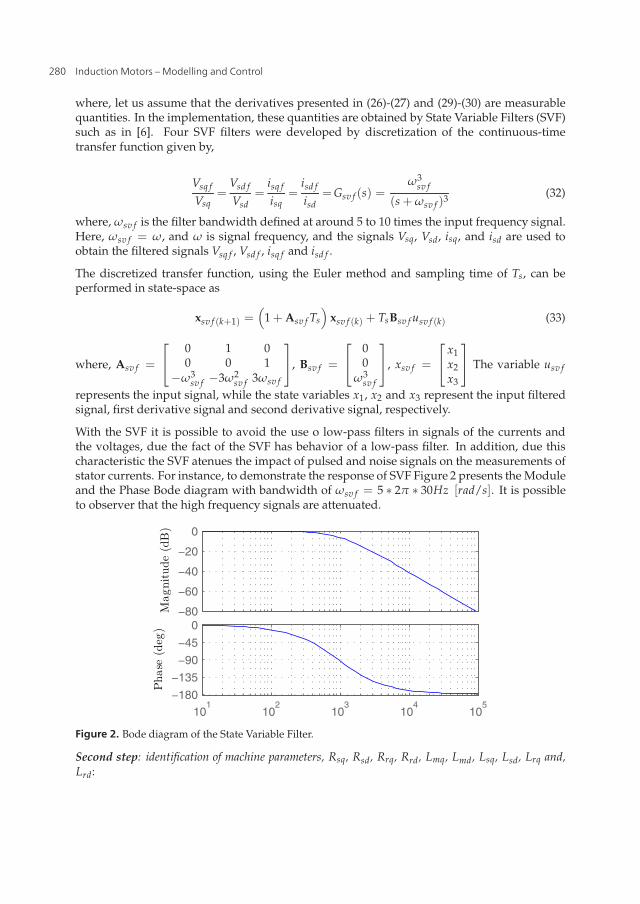
With the SVF it is possible to avoid the use o low-pass filters in signals of the currents andthe voltages, due the fact of the SVF has behavior of a low-pass filter. In addition, due thischaracteristic the SVF atenues the impact of pulsed and noise signals on the measurements ofstator currents. For instance, to demonstrate the response of SVF Figure 2 presents the Moduleand the Phase Bode diagram with bandwidth of ωsv f = 5 ∗ 2π ∗ 30Hz [rad/s]. It is possibleto observer that the high frequency signals are attenuated.
−80
−60
−40
−20
0
Mag
nitu
de(d
B)
101
102
103
104
105
−180
−135
−90
−45
0
Pha
se(d
eg)
Figure 2. Bode diagram of the State Variable Filter.
Second step: identification of machine parameters, Rsq, Rsd, Rrq, Rrd, Lmq, Lmd, Lsq, Lsd, Lrq and,Lrd:
280 Induction Motors – Modelling and Control

Electrical Parameter Identification of Single-Phase Induction Motorby RLS Algorithm 7
The electrical parameters of the SPIM are obtained combining the identified coefficients ofθq(k) and θd(k) in (28) and (31) with the coefficients of the transfer functions (20) and (21),respectively, after the convergence of the RLS algorithm by the equations (34) and (35). In thenumerical solution, the stator and rotor inductances are considered to have the same valuesin each winding.
Rsq =a0q
b0q
Rrq =a1q
b1q− Rsq
Lmq =
√Rrq
(b2
1qRrq − b0q
)b0q
Lsq = Lrq = Rrqb1q
b0q
(34)
Rsd =a0db0d
Rrd =a1db1d
− Rsd
Lmd =
√Rrd
(b2
1dRrd − b0d)
b0d
Lsd = Lrd = Rrdb1db0d
(35)
4. Results and discussions
The RLS parameter identification algorithm presented in this chapter is implemented in aDSP based platform using TMS320F2812 DSP and a three-leg voltage source inverter. Figure 3shows the diagram of the system to obtain the experimental results. The machine used for thevalidation of this methodology is a SPIM of a commercial hermetic refrigeration compressor ofan air conditioning. The SPIM was removed from the hermetic compressor to achieve classicaltests. The machine is two-pole, 220 V type. In the implementation of RLS identificationparameter algorithm, the DC bus was limited in 177V/5A, and the sampling time of 400μswas used.
As described in Sections 2 and 3, the experiment for the parameter identification is achievedwith a standstill rotor. In the first step, a square wave with variable frequency and reducedvoltage supplies the main winding, while the auxiliary winding is opened. The stator currentin the main winding is measured using hall effect sensor. The voltage used in this algorithm isestimated by the product of modulation and DC bus indexes. After the identification for themain winding, the same procedure is repeated for the auxiliary winding. The square wave isused for better excitation of the plant.
The frequency of the supply voltage is 5 Hz in the estimation of resistances to minimize theskin effect, and it is 30 Hz for the estimation of inductances.
281Electrical Parameter Identifi cation of Single-Phase Induction Motor by RLS Algorithm

8 Will-be-set-by-IN-TECH
Figure 3. System diagram for the experimental results.
The first test for the identification of stator and rotor resistances is achieved in the mainwinding. The convergence of coefficients θq for this winding is presented in Fig. 4. Fig. 4 (a)presents the coefficients a1q and a0q, while Fig. 4 (b) gives the coefficients b1q and b0q. In thisexperiment the frequency of the supply voltage is selected on 5 Hz. As presented in figures,the coefficient convergence is fast and it is excited by the reset of the covariance matrix (P).Here, the reset of the covariance matrix (P) is used to avoid that this matrix reach zero andconsequently loses the ability of to update the parameter matrix (θq(k)). Some oscillationsare introduced every time that the covariance matrix (P) is reset, but the convergence ofcoefficients θq(k) is stable around a region.
The aim of the algorithm (13)-(17) is to identify a set of parameters that produce a gooddynamic response such as real dynamic response of the induction machine. If it is necessary toensure the parameter convergence to the true values the Lemma 12.5.2 (Persistent Excitation)of [16] must be satisfied. However, in practical implementations the designer normallyunknown the exactly parameter values due the assumptions and approximations made todevelop the mathematical model of the plant, and due the presence of unmodulated dynamicsin the system, such as the measurement and drive systems.
The coefficients used in the electrical parameter calculation are the final values of Fig 4. Thecoefficient convergence for d axis has behavior similar to coefficient convergence for q axis inFig. 4.
Table 1 shows the final obtained coefficients a1q, a0q, b1q, and b0q in a q axis when the voltagefrequency is 5 Hz and 30 Hz. Table 2 shows the final obtained coefficients a1d, a0d, b1d, and b0din a d axis when the voltage frequency is 5 Hz and 30 Hz. From Fig. 4 it can be observed thatthe coefficient convergence is fast.
5 Hz 30 Hz
a1q 244.27 707.64a0q 447.96 8084.14b1q 24.82 27.73b0q 128.58 2913.7
Table 1. Final convergence for coefficients of the main winding.
282 Induction Motors – Modelling and Control

Electrical Parameter Identification of Single-Phase Induction Motorby RLS Algorithm 9
0 2 4 6 8 10−100
0
100
200
300
400
500
600
time (s)
a1q
a0q
(a)
0 2 4 6 8 10−50
0
50
100
150
200
time (s)
b1q
b0q
(b)
Figure 4. Coefficients convergence.
5 Hz 30 Hz
a1d 246.15 779.65a0d 559.4 3304.5b1d 9.83 17.62b0d 43.67 2448.17
Table 2. Final convergence for coefficients of the auxiliary winding.
The electrical parameters of the induction machine are obtained combining the final valueof coefficients in Table 1 and Table 2 with the equations (34) and (35), respectively. Table 3presents the identified electrical parameters of SPIM. In this study we also make a comparisonwith the results obtained by classical methods, thus, the SPIM identified by RLS algorithm is
283Electrical Parameter Identifi cation of Single-Phase Induction Motor by RLS Algorithm

10 Will-be-set-by-IN-TECH
also tested using no-load and standstill classical methods. The electrical parameters estimatedwhen the SPIM is tested by classical methods are shown in Table 4.
Rsq Rrq Lmq Lsq = Lrq
Identified 3.62Ω 6.27Ω 0.2186H 0.2376H
Rsd Rrd Lmd Lsd = Lrd
Identified 12.79Ω 12.23Ω 0.2849H 0.3142H
Table 3. Experimental identified electrical parameters by RLS algorithm.
Rsq Rrq Lmq Lsq = Lrq
Estimated 3.95Ω 5.1506Ω 0.2149H 0.2292H
Rsd Rrd Lmd Lsd = Lrd
Estimated 11.95Ω 8.6463Ω 0.382H 0.401H
Table 4. Electrical parameters estimated by classical tests.
Aiming the model validation, two experiments are carried out. In the first experiment, theSPIM is driven by a v/f strategy at no-load operation, thus, the main and the auxiliarywindings are supplied by controlled voltages varying the frequency from zero until asteady-state condition. The rotor speed and the stator currents are also measured. Thesemeasurements are recorded for posterior comparison with simulated values.
The model of single-phase induction machine presented in equations (7)-(10) is simulatedusing the estimated parameters of the machine by RLS algorithm given in Table 3. The modelis also simulated using the parameters estimated by the classical methods presented in Table 4.The simulated stator currents are compared with the measured stator currents. The inductionmotor model equations (7)-(10) are discretized using the Euler Method in the same frequencyof the experimental commutation for this test at 5 kHz. The recorded rotor speed is used inthe simulated model to make it independent of the mechanical parameters.
In the first experimental result, the frequency of stator voltages varies from zero until 25Hz and it is fixed in 25 Hz, by the v/f method. The recorded voltage values are used tosupply the SPIM model in the simulation. Thus, from the same input voltages, Fig. 5 showscurrents simulated and measured for the main winding in the first experiment. Fig. 5 (a)presents the comparison between the simulation of isq current with parameters estimated byRLS algorithm, and the experimental measurement of isq current, and Fig 5 (b) presents thecomparison of the isq current when the simulations is carried out with parameters estimatedby classical tests.
Fig. 6 presents a detail of the comparison between the measured and the simulated currentsin steady-state condition for the main winding. In Fig. 6 (a) the comparison betweenexperimental current and simulated current is presented when the SPIM parameters areestimated by RLS algorithm, while Fig. 6 (b) presents the comparison between experimentalcurrent and simulated current when the SPIM parameters are estimated by classical tests.
Fig. 7 presents a comparison among isd currents on the first experiment. Fig. 7 (a) shows thesimulated current using parameters estimated by RLS algorithm in the SPIM model and the
284 Induction Motors – Modelling and Control

Electrical Parameter Identification of Single-Phase Induction Motorby RLS Algorithm 11
0 0.2 0.4 0.6 0.8 1 1.2−6
−4
−2
0
2
4
6
time (s)
i sq
(A)
experimental
RLS
(a)
0 0.2 0.4 0.6 0.8 1 1.2−6
−4
−2
0
2
4
6
time (s)
i sq
(A)
experimental
classical
(b)
Figure 5. Comparison among measured and simulated currents for the first test. (a) Simulated isq usingparameters estimated with RLS algorithm and measured isq current. (b) Simulated isq current usingparameters estimated by classical tests and measured isq current.
measured isd current. Fig. 7 (b) gives the simulated current using parameters estimated byclassical tests and the measured current.
Fig. 8 shows the comparison between isd currents in steady-state condition, Fig. 8 (a) givesthe comparison between the measured isd current and the simulated isd current using SPIMparameters estimated by the RLS algorithm, whereas, Fig. 8 (b) presents the comparison
285Electrical Parameter Identifi cation of Single-Phase Induction Motor by RLS Algorithm

12 Will-be-set-by-IN-TECH
1.04 1.05 1.06 1.07 1.08 1.09 1.1 1.11 1.12−3
−2
−1
0
1
2
3
time (s)
i sq
(A)
experimental
simulated − RLS
(a)
1.04 1.05 1.06 1.07 1.08 1.09 1.1 1.11 1.12−3
−2
−1
0
1
2
3
time (s)
i sq
(A)
experimental
simulated − classical
(b)
Figure 6. Comparison between measured and simulated currents at 25 Hz. (a) Simulated (RLS -Parameters) and measured isq currents. (b) Simulated (Classical - Parameters) and measured isq currents.
between the measured isd current and the simulated isd current using classical method forparameter estimation.
From Figures 5-8 it is possible to observer the good matching between the simulated andexperimental currents for the q and d axes. In addition, some small discrepancies are foundin these figures due the parameter inaccuracies and unmodulated effects (for instance themeasurement and drive systems).
The advantage of the methodology presented in this chapter employing the RLS algorithmis that some types of applications, such as hermetic compressor, it is impossible carriedout classical tests for estimation of the electrical parameters of the SPIM. In addition, themethodology has simplicity in implementation.
In the second experiment, the frequency of the supplied voltages of SPIM varies from zerountil 30 Hz, and it is fixed at 30 Hz. As in the previous test, this is a no-load test and the SPIMis driven by a v/f strategy. The stator currents and rotor speed are measured and recorded.
286 Induction Motors – Modelling and Control

Electrical Parameter Identification of Single-Phase Induction Motorby RLS Algorithm 13
0 0.2 0.4 0.6 0.8 1 1.2
−3
−2
−1
0
1
2
3
time (s)
i sd
(A)
experimental
RLS
(a)
0 0.2 0.4 0.6 0.8 1 1.2
−3
−2
−1
0
1
2
3
time (s)
i sd
(A)
experimental
classical
(b)
Figure 7. Comparison among isd currents in first test. (a) Simulated isd current by RLS parameterestimation and measured isd current. (b) Simulated isd current by classical tests and measured isd current.
Fig. 9 presents a comparison between measured and simulated isq currents in steady-steadcondition. In Fig. 9 (a) shows the measured isq current and the simulated isq current usingparameters estimated by RLS algorithm on the SPIM model, while Fig. 9 (b) gives themeasured isq and the simulated isq current using parameters estimated by classical tests.
Fig. 10 presents a comparison between isd currents in steady-state condition for the secondtest.
287Electrical Parameter Identifi cation of Single-Phase Induction Motor by RLS Algorithm

14 Will-be-set-by-IN-TECH
1.04 1.05 1.06 1.07 1.08 1.09 1.1 1.11 1.12
−1.5
−1
−0.5
0
0.5
1
1.5
time (s)
i sd
(A)
experimental
simulated − RLS
(a)
1.04 1.05 1.06 1.07 1.08 1.09 1.1 1.11 1.12
−1.5
−1
−0.5
0
0.5
1
1.5
time (s)
i sd
(A)
experimental
simulated − classical
(b)
Figure 8. Comparison between isd currents at 25 Hz. (a) Simulated (RLS - parameter) and measured isdcurrents. (b) Simulated (classical tests) and measured isd currents.
288 Induction Motors – Modelling and Control

Electrical Parameter Identification of Single-Phase Induction Motorby RLS Algorithm 15
1.04 1.05 1.06 1.07 1.08 1.09 1.1 1.11 1.12
−3
−2
−1
0
1
2
3
time (s)
i sq
(A)
experimental
simulated − RLS
(a)
1.04 1.05 1.06 1.07 1.08 1.09 1.1 1.11 1.12
−3
−2
−1
0
1
2
3
time (s)
i sq
(A)
experimental
simulated − classical
(b)
Figure 9. Comparison between isq currents at 30 Hz in steady-state condition. (a) Simulated (RLS -parameter) and measured isq currents. (b) Simulated (classical tests) and measured isq currents.
289Electrical Parameter Identifi cation of Single-Phase Induction Motor by RLS Algorithm

16 Will-be-set-by-IN-TECH
1.04 1.05 1.06 1.07 1.08 1.09 1.1 1.11 1.12
−1
−0.5
0
0.5
1
time (s)
i sd
(A)
experimental
simulated − RLS
(a)
1.04 1.05 1.06 1.07 1.08 1.09 1.1 1.11 1.12
−1
−0.5
0
0.5
1
time (s)
i sd
(A)
experimental
simulated − classical
(b)
Figure 10. Comparison between isd currents at 30 Hz. (a) Simulated (RLS - parameter) and measured isdcurrents. (b) Simulated (classical tests) and measured isd currents.
5. Conclusion
A methodology for single-phase induction machine parameter identification was presentedand discussed in this chapter. The machine tested was a SPIM used in a hermetic compressorof air conditioning. Using the proposed methodology it is possible to obtain all electricalparameters of SPIM for simulation and design of high performance vector control andsensorless SPIM drives. The main contribution of this study is the development of anautomatized procedure for the identification of all electrical parameters of SPIM, such asthe SPIM used in hermetic conditioning compressor. Experimental results demonstrate theeffectiveness of the method. Some experimental comparisons among measurements andsimulations using parameters estimated by classical tests and simulations using parametersobtained by RLS algorithm are presented. From Table 3 and Table 4 it is possible to observethat the parameters obtained with RLS algorithm converge to different values compared toclassical tests. However, the results in Fig. 5 - 10 show that the parameters estimated with RLSalgorithm present equivalent dynamical behavior compared with parameters estimated byclassical methods. The methodology proposed in this chapter can be extended to be appliedin other SPIM drives and three-phase induction motor drives.
290 Induction Motors – Modelling and Control

Electrical Parameter Identification of Single-Phase Induction Motorby RLS Algorithm 17
Author details
Rodrigo Padilha VieiraFederal University of Pampa - UNIPAMPA, Federal University of Santa Maria - UFSM, PowerElectronics and Control Research Group - GEPOC, Brazil
Rodrigo Zelir AzzolinFederal University of Rio Grande - FURG, Federal University of Santa Maria - UFSM, PowerElectronics and Control Research Group - GEPOC, Brazil
Cristiane Cauduro GastaldiniFederal University of Pampa - UNIPAMPA, Federal University of Santa Maria - UFSM, PowerElectronics and Control Research Group - GEPOC, Brazil
Hilton Abílio GründlingFederal University of Santa Maria - UFSM, Power Electronics and Control Research Group - GEPOC,Brazil
6. References
[1] Amin, A., El Korfally, M., Sayed, A. & Hegazy, O. [2009]. Efficiency optimizationof two-asymmetrical-winding induction motor based on swarm intelligence, IEEETransactions on Energy Conversion 24(1): 12 –20.
[2] Azzolin, R. Z., Gastaldini, C. C., Vieira, R. P. & Gründling, H. A. [2011]. A RMRACParameter Identification Algorithm Applied to Induction Machines, Electric Machines andDrives, Miroslav Chomat (Ed.), InTech.
[3] Azzolin, R. Z. & Gründling, H. A. [2009]. A MRAC parameter identification algorithm forthree-phase induction motors, IEEE International Electric Machines and Drives Conference,IEMDC ’09., pp. 273 –278.
[4] Blaabjerg, F., Lungeanu, F., Skaug, K. & Tonnes, M. [2004]. Two-phase induction motordrives, IEEE Industry Applications Magazine 10(4): 24–32.
[5] Bose, B. [2009]. Power electronics and motor drives recent progress and perspective,IEEE Transactions on Industrial Electronics 56(2): 581 –588.
[6] Câmara, H. T., Cardoso, R. C., Azzolin, R. Z., Pinheiro, H. & Gründling, H. A. [2006].Low-cost sensorless induction motor speed control, IEEE 32nd Annual Conference onIndustrial Electronics, IECON 2006, pp. 1200 –1205.
[7] de Rossiter Corrêa, M., Jacobina, C., Lima, A. & da Silva, E. [2000]. Rotor-flux-orientedcontrol of a single-phase induction motor drive, IEEE Transactions on Industrial Electronics47(4): 832–841.
[8] Donlon, J., Achhammer, J., Iwamoto, H. & Iwasaki, M. [2002]. Power modules forappliance motor control, IEEE Industry Applications Magazine 8(4): 26–34.
[9] Finch, J. & Giaouris, D. [2008]. Controlled AC electrical drives, IEEE Transactions onIndustrial Electronics 55(2): 481 –491.
[10] Holtz, J. [2005]. Sensorless control of induction machines: With or without signalinjection?, IEEE Transactions on Industrial Electronics 53(1): 7 – 30.
[11] Hrabovcova, V., Kalamen, L., Sekerak, P. & Rafajdus, P. [2010]. Determination of singlephase induction motor parameters, International Symposium on Power Electronics ElectricalDrives Automation and Motion (SPEEDAM), pp. 287 –292.
[12] Jemli, M., Ben Azza, H., Boussak, M. & Gossa, M. [2009]. Sensorless indirect stator fieldorientation speed control for single-phase induction motor drive, IEEE Transactions onPower Electronics 24(6): 1618–1627.
291Electrical Parameter Identifi cation of Single-Phase Induction Motor by RLS Algorithm

18 Will-be-set-by-IN-TECH
[13] Koubaa, Y. [2004]. Recursive identification of induction motor parameter, SimulationModelling Practice and Theory 12(5): 368–381.
[14] Krause, P. C., Wasynczuk, O. & Sudhoff, S. D. [2002]. Analysis of Electric Machinery andDrive Systems, 2 edn, Wiley-IEEE Press.
[15] Lascu, C., Boldea, I. & Blaabjerg, F. [2005]. Comparative study of adaptive and inherentlysensorless observers for variable-speed induction-motor drives, IEEE Transactions onIndustrial Electronics 53(1): 57 – 65.
[16] Middleton, R. H. & Goodwin, G. C. [1990]. Digital Control and Estimation - A UnifiedApproach, 1 edn, Prentice Hall.
[17] Myers, M., Bodson, M. & Khan, F. [2011]. Determination of the parameters ofnon-symmetric induction machines, Annual IEEE Applied Power Electronics Conference andExposition (APEC), pp. 1028 –1033.
[18] Nied, A., de Oliveira, J., de Farias Campos, R., Jr., S. I. S. & de Souza Marques, L. C.[2011]. Space Vector PWM-DTC Strategy for Single-Phase Induction Motor Control, ElectricMachines and Drives, Miroslav Chomat (Ed.), InTech.
[19] Orlowska-Kowalska, T. & Dybkowski, M. [2010]. Stator-current-based mras estimatorfor a wide range speed-sensorless induction-motor drive, IEEE Transactions on IndustrialElectronics 57(4): 1296 –1308.
[20] Rao, S., Buss, M. & Utkin, V. [2009]. Simultaneous state and parameter estimationin induction motors using first- and second-order sliding modes, IEEE Transactions onIndustrial Electronics 56(9): 3369 –3376.
[21] Ribeiro, L. A. S., Jacobina, C. B. & Lima, A. M. N. [1995]. Dynamic estimation of theinduction machine parameters and speed, 26th Annual IEEE Power Electronics SpecialistsConference, PESC ’95. 2: 1281–1287 vol.2.
[22] Toliyat, H., Levi, E. & Raina, M. [2003]. A review of RFO induction motor parameterestimation techniques, IEEE transactions on Energy conversion 18(2): 271–283.
[23] Utkin, V. [1993]. Sliding mode control design principles and applications to electricdrives, IEEE Transactions on Industrial Electronics 40(1): 23 –36.
[24] Vaez-Zadeh, S. & Reicy, S. [2005]. Sensorless vector control of single-phase inductionmotor drives, Proceedings of the Eighth International Conference on Electrical Machines andSystems, 2005. ICEMS 2005 3: 1838–1842 Vol. 3.
[25] van der Merwe, C. & van der Merwe, F. [1995]. A study of methods to measure theparameters of single-phase induction motors, IEEE Transactions on Energy Conversion10(2): 248 –253.
[26] Vas, P. [1998]. Sensorless Vector and Direct Torque Control, Oxford Univ. Press.[27] Velez-Reyes, M., Minami, K. & Verghese, G. [1989]. Recursive speed and parameter
estimation for induction machines, Conference Record of the Industry Applications SocietyAnnual Meeting, 1989. pp. 607–611 vol.1.
[28] Vieira, R. P., Azzolin, R. Z., Gastaldini, C. C. & Gründling, H. [2010]. Electricalparameters identification of hermetic refrigeration compressors with single-phaseinduction machines using RLS algorithm, International Conference on Electrical Machines,2010. ICEM 2010.
[29] Vieira, R. P., Azzolin, R. Z. & Gründling, H. A. [2009]. A sensorless single-phaseinduction motor drive with a MRAC controller, 35st Annual Conference of IEEE IndustrialElectronics Society, 2009., pp. 1003 –1008.
[30] Vieira, R. P., Azzolin, R. Z. & Gründling, H. A. [2009]. Parameter identification of asingle-phase induction motor using RLS algorithm, Brazilian Power Electronics Conference,2009. COBEP ’09., pp. 517 –523.
[31] Zahedi, B. & Vaez-Zadeh, S. [2009]. Efficiency optimization control of single-phaseinduction motor drives, IEEE Transactions on Power Electronics 24(4): 1062 –1070.
292 Induction Motors – Modelling and Control