electrical machines laboratory – 2 lab manual lab_2 iv sem.pdf · syllabus electrical machines...
TRANSCRIPT
QMP 7.1 D/F
Channabasaveshwara Institute of Technology (An ISO 9001:2008 Certified Institution)
NH 206 (B.H. Road), Gubbi, Tumkur – 572 216. Karnataka.
Department of Electrical & Electronics Engineering
ELECTRICAL MACHINES LABORATORY – 2
Lab Manual
15EEL47
B.E - IV Semester
2016-17
Name: __________________________________________________
USN: ___________________________________________________
Batch: ___________________Section: ________________

Channabasaveshwara Institute of Technology (An ISO 9001:2008 Certified Institution)
NH 206 (B.H. Road), Gubbi, Tumkur – 572 216. Karnataka.
Department of Electrical & Electronics Engineering
ELECTRICAL MACHINES LABORATORY – 2
Lab Manual Version 1.0
Feb 2017
Prepared by: Reviewed by:
1. R Sekar V.C Kumar Associate Professor Professor 2. Murugesh P D Assistant Professor 3. Praveen M G Assistant Professor 4. Tejashwini M V Assistant Professor
Approved by:
V.C Kumar Professor & Head Dept. of EEE

SYLLABUS
ELECTRICAL MACHINES LABORATORY – 2
Sub Code: 15EEL47 IA Marks: 20
Hrs/week: 03 Exam Hours: 03
Total Hours: 42 Exam Marks: 80
1. Load test on dc shunt motor to draw speed – torque and horse power – efficiency
characteristics.
2. Field Test on dc series machines.
3. Speed control of dc shunt motor by armature and field control.
4. Swinburne's Test on dc motor.
5. Retardation test on dc shunt motor.
6. Regenerative test on dc shunt machines.
7. Load test on three phase induction motor.
8. No load and Blocked rotor test on three phase induction motor to draw (i) equivalent
circuit and (ii) circle diagram. Determination of performance parameters at different load
conditions from (i) and (ii).
9. Load test on induction generator.
10. Load test on single phase induction motor to draw output versus torque, current, power
and efficiency characteristics.
11. Conduct suitable tests to draw the equivalent circuit of single phase induction motor and
determine performance parameters.
12. Conduct an experiment to draw V and Λ curves of synchronous motor at no load and load
conditions.

INDEX PAGE
Note:
If the student fails to attend the regular lab, the experiment has to be completed in the same week. Then the manual/observation and record will be evaluated for 50% of maximum marks.
Sl.No Name of the Experiment
Date
Man
ual M
ark
s
(Max .
20
)
Reco
rd M
ark
s
(Max.
10
)
Sig
natu
re
(Stu
den
t)
Sig
natu
re
(Facu
lty)
Conduction Repetition Submission of
Record
Average

Course objectives & outcomes
Course objectives:
1. To perform tests on dc machines to determine their characteristics.
2. To control the speed of dc motor
3. To conduct test for pre-determination of the performance characteristics of dc machines
4. To conduct load test on single phase and three phase induction motor.
5. To conduct test on induction motor to determine the performance characteristics
6. To conduct test on synchronous motor to draw the performance curves.
Course outcomes:
At the end of the course the student will be able to:
1. Test dc machines to determine their characteristics.
2. Control the speed of dc motor
3. Pre-determine the performance characteristics of dc machines by conducting suitable tests.
4. Perform load test on single phase and three phase induction motor to assess its performance.
5. Conduct test on induction motor to pre-determine the performance characteristics
6. Conduct test on synchronous motor to draw the performance curves.

Channabasaveshwara Institute of Technology (An ISO 9001:2008 Certified Institution)
NH 206 (B.H. Road), Gubbi, Tumkur – 572 216. Karnataka.
OUR VISION
To create centers of excellence in education and to serve the society by enhancing the quality
of life through value based professional leadership.
OUR MISSION
To provide high quality technical and professionally relevant education in a diverse
learning environment.
To provide the values that prepare students to lead their lives with personal integrity,
professional ethics and civic responsibility in a global society.
To prepare the next generation of skilled professionals to successfully compete in the
diverse global market.
To promote a campus environment that welcomes and honors women and men of all
races, creeds and cultures, values and intellectual curiosity, pursuit of knowledge and
academic integrity and freedom.
To offer a wide variety of off-campus education and training programmes to
individuals and groups.
To stimulate collaborative efforts with industry, universities, government and
professional societies.
To facilitate public understanding of technical issues and achieve excellence in the
operations of the institute.

Channabasaveshwara Institute of Technology
(An ISO 9001:2008 Certified Institution)
NH 206 (B.H. Road), Gubbi, Tumkur – 572 216. Karnataka.
DEPARTMENT OF ELECTRICAL AND ELECTRONICS ENGINEERING
VISION:
To be a department of excellence in electrical and electronics Engineering education and
Research, thereby to provide technically competent and ethical professionals to serve the
society.
MISSION:
To provide high quality technical and professionally relevant education in the field of
electrical engineering.
To prepare the next generation of electrically skilled professionals to successfully
compete in the diverse global market.
To nurture their creative ideas through research activities.
To promote research and development in electrical technology and management for the
benefit of the society.
To provide right ambience and opportunities for the students to develop into creative,
talented and globally competent professionals in electrical sector.
Caution
1. Do not play with electricity.
2. Carelessness not only destroys the valuable equipment in the lab but also costs your life.
3. Mere conductivity of the experiment without a clear
knowledge of the theory is of no value.
4. Before you close a switch, think of the consequences.
5. Do not close the switch until the faculty in charge checks the circuit.

‘General Instructions to Students’
1. Students should come with thorough preparation for the experiment to
be conducted. 2. Students will not be permitted to attend the laboratory unless they bring
the practical record fully completed in all respects pertaining to the experiment conducted in the previous class.
3. Name plate details including the serial number of the machine used for the experiment should be invariably recorded.
4. Experiment should be started only after the staff-in-charge has checked
the circuit diagram.
5. All the calculations should be made in the observation book. Specimen calculations for one set of readings have to be shown in the practical record.
6. Wherever graphs are to be drawn, A-4 size graphs only should be used
and the same should be firmly attached to the practical record.
7. Practical record should be neatly maintained.
8. They should obtain the signature of the staff-in-charge in the observation book after completing each experiment.
9. Theory regarding each experiment should be written in the practical
record before procedure in your own words.
10. Come prepared to the lab with relevant theory about the Experiment you are conducting. 11. While using Electrolytic capacitors, connect them in the right polarity. 12. Before doing the circuit connection, check the active components, equipments etc, for their good working condition. 13. Do not use the multimeter, if the battery indication is low.
Channabasaveshwara Institute of Technology (An ISO 9001:2008 Certified Institution)
NH 206 (B.H. Road), Gubbi, Tumkur – 572 216. Karnataka.
DEPARTMENT OF ELECTRICAL & ELECTRONICS ENGG.
CONTENTS
First Cycle Experiments
Exp.No. Title of the Experiment Page
No
1 Load test on three phase induction motor. 02
2 Load test on single phase induction motor 06
3 Load test on induction generator. 10
4 Load test on dc shunt motor 14
5 Speed control of dc shunt motor by armature and field control.
18
6 Swinburne's Test on dc motor. 22
Second Cycle Experiments
Exp.No.
Title of the Experiment Page No
7 Retardation test on dc shunt motor. 26
8 Field Test on dc series machines. 30
9 Regenerative test on dc shunt machines. 36
10 No load and Blocked rotor test on 3 phase Induction Motor 40
11 Conduct an experiment to draw V and Λ curves of synchronous motor at no load and load conditions.
48
12 Conduct suitable tests to draw the equivalent circuit of single phase induction motor
52
Question bank 57
Viva - voce Questions 60
References 64
Appendix 65

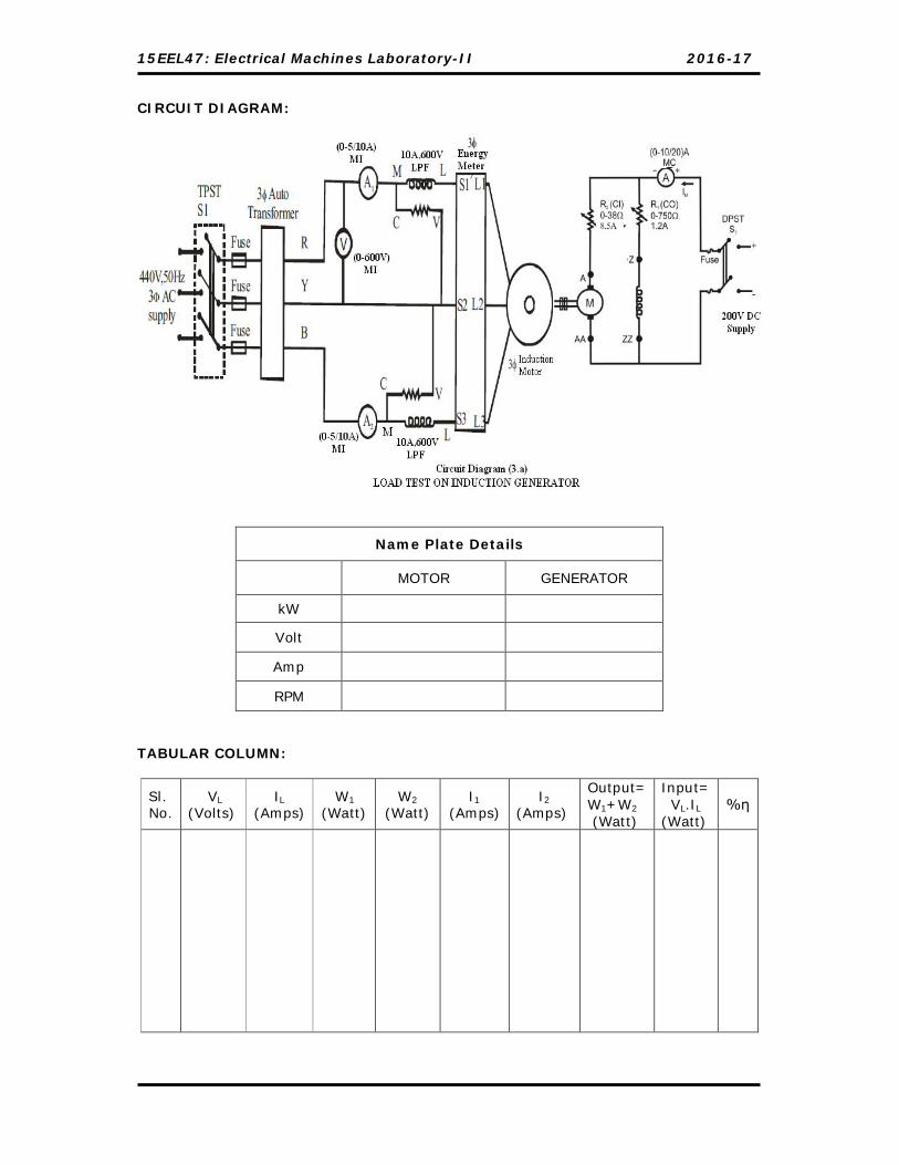
15EEL47: Electrical Machines Laboratory-II 2016-17
CIRCUIT DIAGRAM:
Name Plate Details KW
Volt
Amp
RPM
MODEL GRAPH:

15EEL47: Electrical Machines Laboratory-II 2016-17
Dept. of EEE, C.I.T, Gubbi, 572 216 Page No.2
Experiment No. 1 Date: __/__/_____ LOAD TEST ON 3-Ф INDUCTION MOTOR
AIM: To conduct load test on three-phase induction motor and plot the following
characteristics. i) BHP V/S slip ii) BHP V/S η
iii) BHP V/S pf iv) Torque V/S speed.
APPARATUS REQUIRED:
Sl. No Particulars Range Type Quantity
01. Voltmeter 0-600V MI 01
02. Ammeter 0-10A MI 02
03. Wattmeter 10A, 600V UPF 02
04. Tachometer -- Contact Type
01
PROCEDURE:
1. Connections are made as shown in the circuit diagram (1.a)
2. Measure and notedown the circumference of brake drum by using cotton thread.
3. Spring balances S1 and S2 are kept in zero out-put position by operating the
adjustment wheels T1 and T2.
4. By keeping the 3-Ф auto-transformer voltage in zero out-put position, the supply
switch (S1) is closed.
5. Vary the auto-transformer voltage gradually and apply the rated voltage of
induction motor. [ say 415V]
6. The no-load readings of all the meters and speed are noted down.
7. The Induction motor is loaded gradually by tightening the belt till the rated
current. At each load all the meter readings and speed are noted down.
8. To stop the motor, the load is removed (belt is loosened), the 3-Ф auto-
transformer voltage is reduced to its initial zero out-put position, the supply
switch (S1) is opened.

15EEL47: Electrical Machines Laboratory-II 2016-17
Dept. of EEE, C.I.T, Gubbi, 572 216 Page No.3
TA
BU
LA
R C
OLU
MN
: V
L =
_______ V
olt
s
%η
Slip
Outp
ut
(W
att)
BH
P
T
Tor
que
(K
g-m
) N
Spee
d
(rpm
)
S1~
S2
S2
Kg
S1
Kg
CosФ
Input
(W1+
W2)
(Wat
t)
W2
(Wat
t)
W1
(Wat
t)
A2
(Am
ps)
A1
(Am
ps)
Sl.
No.

15EEL47: Electrical Machines Laboratory-II 2016-17
Dept. of EEE, C.I.T, Gubbi, 572 216 Page No.4
CALCULATION: Circumference of the brake drum = _______ cm = ________m
Radius of the brake drum = r = Circumference of the brake drum = ________meters 2∏ Torque (T) = (S1 ~ S2) * r = ___________Kg-m
BHP = 45002
=
Output in Watts = BHP × 735.5 Input in Watts = (W1 + W2)
Therefore %Efficiency (ŋ) = 100Input
OutPut =
Cos Ф = LL
21
I ..V3 WW
Slip = NN) - (N
S
S
Ns = P
f120 Where P = No. of poles
NOTE: W1 = (k1 × Watt Meter Reading.) Where, k1 = Deflection Scale Full
) CosI(V selsel
W2 = (k2 × Watt Meter Reading.) Where, k2 = Deflection Scale Full
) CosI(V selsel
Signature of Staff-incharge

15EEL47: Electrical Machines Laboratory-II 2016-17
CIRCUIT DIAGRAM:
Name Plate Details KW
Volt
Amp
RPM
TABULAR COLUMN:
Sl. No.
V (Volts)
A (Amps)
W (Watt)
S1
Kg S2
Kg (S1~S2)
Kg
N Speed (rpm)
T Torque (Kg-m)
BHP Output (Watt)
Slip %η
NOTE: 1) W = (k × Watt Meter Reading.) Where, k = Deflection Scale Full
) CosI(V selsel

15EEL47: Electrical Machines Laboratory-II 2016-17
Dept. of EEE, C.I.T, Gubbi, 572 216 Page No.6
Experiment No. 2 Date: __/__/_____
LOAD TEST ON 1-Ф INDUCTION MOTOR
AIM:
To conduct load test on a given 1-Ф induction motor and plot the following
characteristics. i) BHP V/S slip ii) BHP V/S η
iii) BHP V/S pf iv) Torque V/S speed.
APPARATUS REQUIRED:
Sl. No Particulars Range Type Quantity
01. Voltmeter 0-300V MI 01
02. Ammeter 0-5/10A MI 01
03. Wattmeter 10A, 300V UPF 01
04. Tachometer -- Contact Type
01
PROCEDURE:
1. Connections are made as shown in the circuit diagram (2.a)
2. Measure and notedown the circumference of brake drum by using cotton thread.
3. Spring balances S1 and S2 are kept in zero out-put position by operating the
adjustment wheels T1 and T2.
4. By keeping the auto-transformer voltage in zero out-put position, the supply
switch (S1) is closed.
5. Vary the auto-transformer voltage gradually and apply the rated voltage of
induction motor. [ say 230V]
6. The no-load readings of all the meters and speed are noted down.
7. The Induction motor is loaded gradually by tightening the belt till the rated
current. At each load all the meters and speed readings are noted down.
8. To stop the motor, the load is removed (belt is loosened), the auto-transformer
voltage is reduced to its initial zero out-put position, the supply switch (S1) is
opened.

15EEL47: Electrical Machines Laboratory-II 2016-17
MODEL GRAPH:
CALCULATION: Circumference of the brake drum = _______ cm = ________m
Radius of the brake drum (r) = circumference of the break drum = __________meters 2∏ Torque (T) = (S1~ S2) * r = --------------------------------- Kg-m
BHP = 45002
=
Input in Watts = W Output in Watts = BHP × 735.6
CosΦ = I V
W
Slip = NN) - (N
S
S
Ns = P
f120 Where P = No. of poles
Therefore; %Efficiency (ŋ) = 100Input
OutPut

15EEL47: Electrical Machines Laboratory-II 2016-17
Dept. of EEE, C.I.T, Gubbi, 572 216 Page No.8
Signature of Staff-incharge
15EEL47: Electrical Machines Laboratory-II 2016-17
CIRCUIT DIAGRAM:
Name Plate Details
MOTOR GENERATOR
kW
Volt
Amp
RPM
TABULAR COLUMN:
Sl. No.
VL (Volts)
IL (Amps)
W1
(Watt) W2
(Watt) I1
(Amps) I2
(Amps)
Output= W1+W2
(Watt)
Input= VL.IL
(Watt) %η
15EEL47: Electrical Machines Laboratory-II 2016-17
Dept. of EEE, C.I.T, Gubbi, 572 216 Page No.10
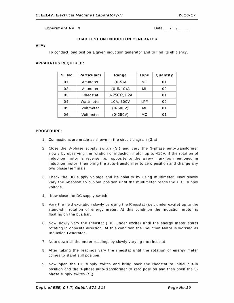
Experiment No. 3 Date: __/__/_____
LOAD TEST ON INDUCTION GENERATOR
AIM:
To conduct load test on a given induction generator and to find its efficiency.
APPARATUS REQUIRED:
Sl. No Particulars Range Type Quantity
01. Ammeter (0-5)A MC 01
02. Ammeter (0-5/10)A MI 02
03. Rheostat 0-750Ώ,1.2A 01
04. Wattmeter 10A, 600V LPF 02
05. Voltmeter (0-600V) MI 01
06. Voltmeter (0-250V) MC 01
PROCEDURE:
1. Connections are made as shown in the circuit diagram (3.a).
2. Close the 3-phase supply switch (S1) and vary the 3-phase auto-transformer slowly by observing the rotation of induction motor up to 415V. if the rotation of induction motor is reverse i.e., opposite to the arrow mark as mentioned in induction motor, then bring the auto-transformer to zero position and change any two phase terminals.
3. Check the DC supply voltage and its polarity by using multimeter. Now slowly vary the Rheostat to cut-out position until the multimeter reads the D.C. supply voltage.
4. Now close the DC supply switch.
5. Vary the field excitation slowly by using the Rheostat (i.e., under excite) up to the stand-still rotation of energy meter. At this condition the Induction motor is floating on the bus bar.
6. Now slowly vary the rheostat (i.e., under excite) until the energy meter starts rotating in opposite direction. At this condition the Induction Motor is working as Induction Generator.
7. Note down all the meter readings by slowly varying the rheostat.
8. After taking the readings vary the rheostat until the rotation of energy meter comes to stand still position.
9. Now open the DC supply switch and bring back the rheostat to initial cut-in position and the 3-phase auto-transformer to zero position and then open the 3-phase supply switch (S1).
15EEL47: Electrical Machines Laboratory-II 2016-17
Dept. of EEE, C.I.T, Gubbi, 572 216 Page No.11
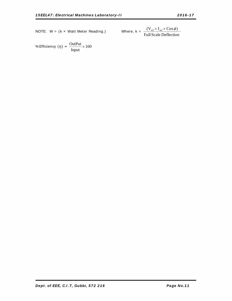
NOTE: W = (k × Watt Meter Reading.) Where, k = Deflection Scale Full
) CosI(V selsel
%Efficiency (ŋ) = 100Input
OutPut

15EEL47: Electrical Machines Laboratory-II 2016-17
Dept. of EEE, C.I.T, Gubbi, 572 216 Page No.12
Signature of Staff-incharge

15EEL47: Electrical Machines Laboratory-II 2016-17
CIRCUIT DIAGRAM:
Name Plate Details
MOTOR GENERATOR
kW
Volt
Amp
RPM
15EEL47: Electrical Machines Laboratory-II 2016-17
Dept. of EEE, C.I.T, Gubbi, 572 216 Page No.14
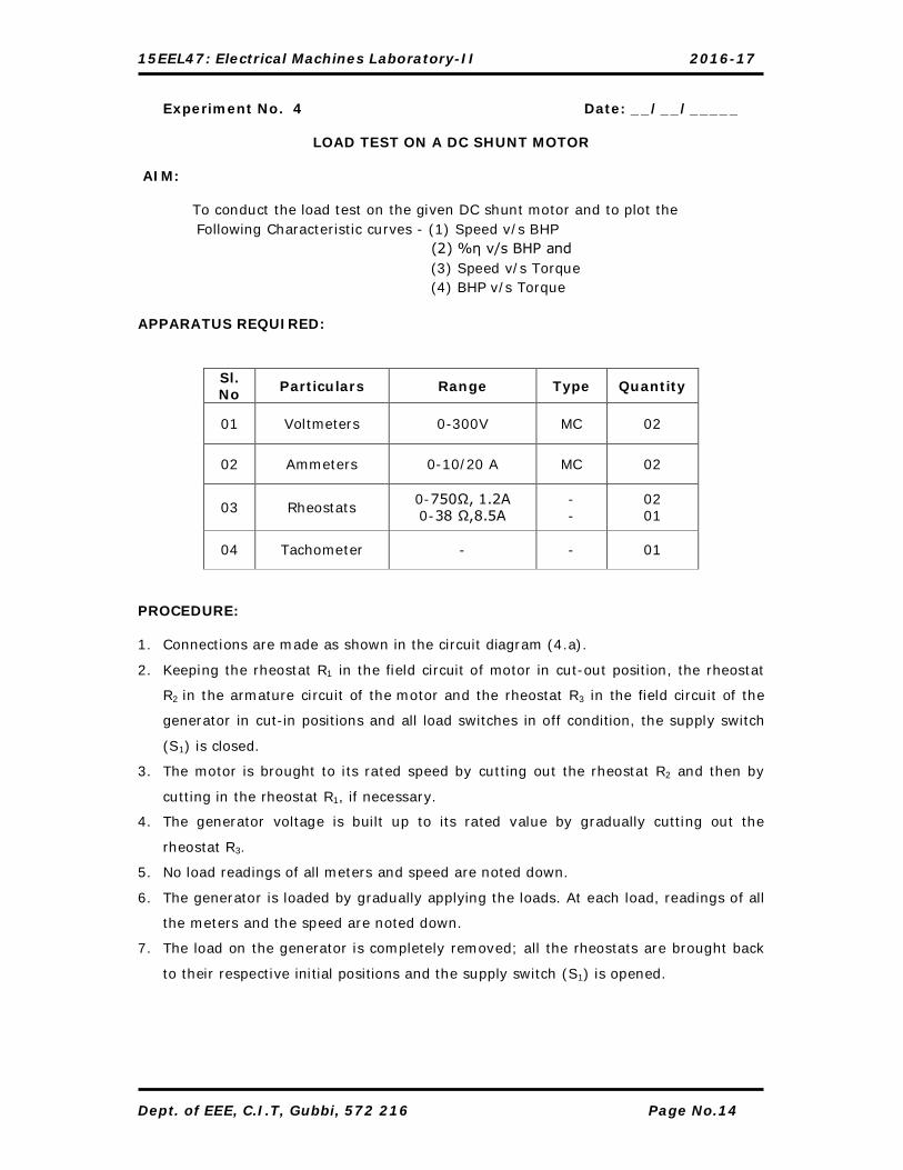
Experiment No. 4 Date: __/__/_____
LOAD TEST ON A DC SHUNT MOTOR
AIM:
To conduct the load test on the given DC shunt motor and to plot the Following Characteristic curves - (1) Speed v/s BHP
(2) %η v/s BHP and (3) Speed v/s Torque (4) BHP v/s Torque APPARATUS REQUIRED: PROCEDURE: 1. Connections are made as shown in the circuit diagram (4.a).
2. Keeping the rheostat R1 in the field circuit of motor in cut-out position, the rheostat
R2 in the armature circuit of the motor and the rheostat R3 in the field circuit of the
generator in cut-in positions and all load switches in off condition, the supply switch
(S1) is closed.
3. The motor is brought to its rated speed by cutting out the rheostat R2 and then by
cutting in the rheostat R1, if necessary.
4. The generator voltage is built up to its rated value by gradually cutting out the
rheostat R3.
5. No load readings of all meters and speed are noted down.
6. The generator is loaded by gradually applying the loads. At each load, readings of all
the meters and the speed are noted down.
7. The load on the generator is completely removed; all the rheostats are brought back
to their respective initial positions and the supply switch (S1) is opened.
Sl. No Particulars Range Type Quantity
01 Voltmeters 0-300V MC 02
02 Ammeters 0-10/20 A MC 02
03 Rheostats 0-750Ω, 1.2A 0-38 Ω,8.5A
- -
02 01
04 Tachometer - - 01

15EEL47: Electrical Machines Laboratory-II 2016-17
TABULAR COLUMN:
Sl. No
Vm (Volt)
Im (Ampere)
VL (Volt)
IL (Ampere)
N (rpm)
Motor O/P
(Watt) BHP % Torque
(Kg-m)
MODEL GRAPHS

15EEL47: Electrical Machines Laboratory-II 2016-17
Dept. of EEE, C.I.T, Gubbi, 572 216 Page No.16
CALCULATIONS: Motor Input = Vm × Im Watt Motor Output = Generator Input Watt Generator Output = VL × IL Watt Assuming generator η as 0.85 Motor output = (VL × IL)/ 0.85 Watt % η motor = (Motor output in watt / motor input in watt) × 100 B.H.P = Motor output in watt / 735.5 Torque = (B.H.P × 4500) / 2 π N Kg-m
Signature of Staff-incharge

15EEL47: Electrical Machines Laboratory-II 2016-17
CIRCUIT DIAGRAM:
MODEL GRAPHS

15EEL47: Electrical Machines Laboratory-II 2016-17
Dept. of EEE, C.I.T, Gubbi, 572 216 Page No.18
Experiment No. 5 Date: __/__/_____
SPEED CONTROL OF D.C SHUNT MOTOR
AIM: To control the speed of D.C. Shunt motor by- (1) Armature control method
(2) Field Flux control method
APPARATUS REQUIRED:
PROCEDURE:
I. Armature Control Method
1. Connections are made as shown in the circuit diagram (5.a) 2. Keeping the rheostat R1 in the field circuit of motor in cut-out position, the
rheostat R2 in the armature circuit of the motor in cut-in positions the supply switch (S1) is closed.
3. Field current (If) is adjusted to a constant value by adjusting the rheostat R1 and the rheostat R2 is gradually cut-out in steps and at each step the readings of voltmeter and the speed are noted down.
4. The above procedure is repeated for another value of field currents. 5. All rheostats are brought back to their respective initial Positions and the
supply switch (S1) is opened II. Field Flux Control Method
1. Keeping the rheostat R1 in the field circuit of the motor in cut-out position, the rheostat R2 in the armature circuit of the motor in cut-in position, the supply switch (S1) is closed.
2. The rheostat R2 is adjusted to get the required voltage across the armature
3. The rheostat R1 is gradually brought to cut-in in steps and at each step the readings of ammeter and speed are noted down.
[Note: The rheostat R1is cut-in till the speed is little above the rated speed of Motor]
4. The experiment is repeated for another value of armature voltage.
5. All rheostats are brought back to their respective initial Positions and the supply switch (S1) is opened.
6. The graphs are plotted as shown in model graphs (1 and 2).
Sl. No. Particulars Range Type Quantity
01 Voltmeter 0-300V MC 01
02 Ammeter 0-1/2A MC 01
03 Rheostats 0-38 Ω,8.5A 0-750Ω,1.2A -
01 01
04 Tachometer - - 01

15EEL47: Electrical Machines Laboratory-II 2016-17
Dept. of EEE, C.I.T, Gubbi, 572 216 Page No.19
TABULAR COLUMN:
1. Armature Control Method
If = ______Ampere (Constant) If= _______Ampere (Constant)
Sl. No Va Volts
Speed rpm
Sl. No Va Volts
Speed rpm
2. Field Flux Control Method Armature Voltage = ____Volt (Constant) Armature Voltage =____Volt (Constant)
Sl. No
If Ampere Speed rpm
Sl. No
If Ampere Speed rpm

15EEL47: Electrical Machines Laboratory-II 2016-17
Dept. of EEE, C.I.T, Gubbi, 572 216 Page No.20
Signature of Staff-incharge

15EEL47: Electrical Machines Laboratory-II 2016-17
CIRCUIT DIAGRAM:

15EEL47: Electrical Machines Laboratory-II 2016-17
Dept. of EEE, C.I.T, Gubbi, 572 216 Page No.22
Experiment No. 6 Date: __/__/_____
SWINBURNE’S TEST AIM:
To determine the constant losses and hence to find the efficiency of a given DC Machine at any desired load.
APPARATUS REQUIRED:
PROCEDURE:
1. Connections are made as shown in the circuit diagram (6.a).
2. Keeping the rheostat R1 in the field circuit of motor in cut-out position, the
rheostat R2 in the armature circuit of the motor in cut-in positions the supply
switch(S1) is closed.
3. The motor is brought to its rated speed by cutting out the rheostat R2 and cutting
in the rheostat R1 if necessary.
4. Readings of all the meters and speed are noted down.
5. All the rheostats are brought back to their respective initial positions and the
supply switch (S1) is opened.
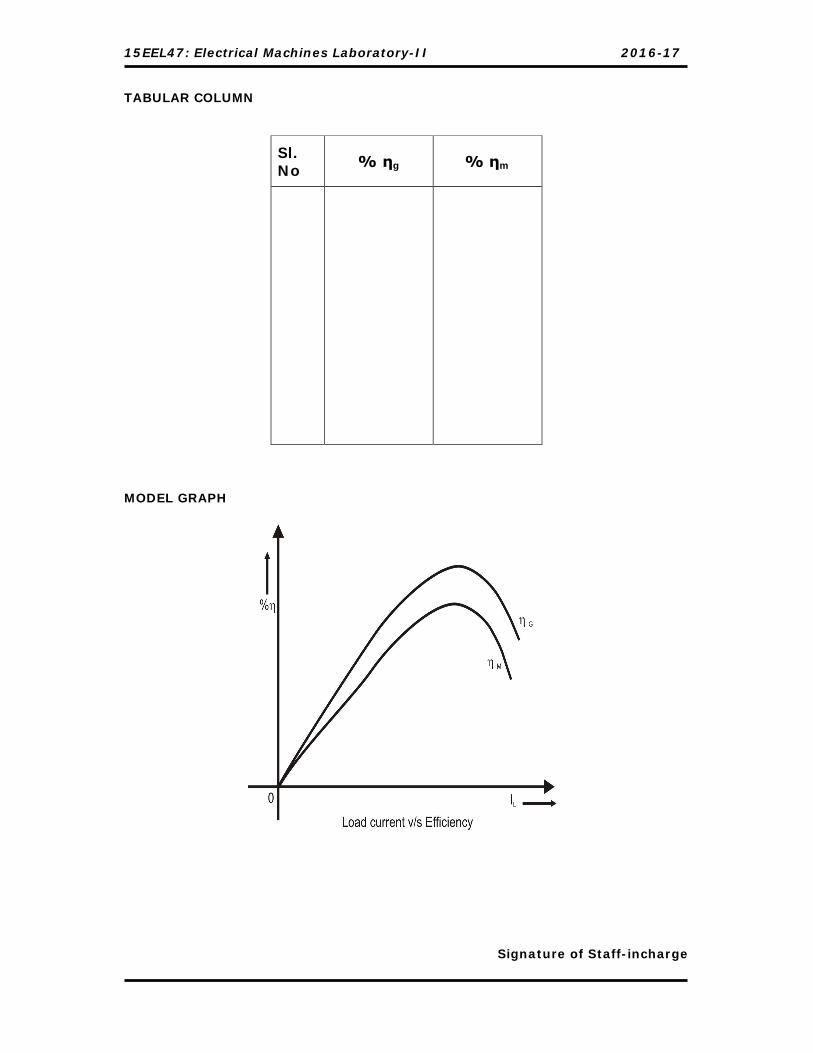
6. The graph of Efficiency v/s Load current is plotted as shown in Model Graph.
Determination of Armature Resistance (Ra) by V-I method:
a. Connections are made as shown in the circuit diagram(6.b)
b. Keeping the rheostat in cut-in position, the supply switch (S1) is closed,
Rheostat is adjusted to any value of current (say 1A) and the readings of
ammeter and voltmeter are noted down.
c. The supply switch (S1) is opened.
Sl. No. Particulars Range Type Quantity
01 Voltmeters 0-300V 0-30V
MC MC
01 01
02 Ammeters 0-5A
0-1/2A
MC
MC
01
01
03 Rheostats 0-750Ω,1.2A 0-38Ω,8.5A
- 01 01
04 Tachometer - - 01

15EEL47: Electrical Machines Laboratory-II 2016-17
TABULAR COLUMN: Tabulation of Results:
Determination of Armature Resistance (Ra):
MODEL GRAPH:
Sl. No VL
Volt IL
Amp If
Amp
Sl. No.
Load (X)
% m % g
1.
Full Load
2.
¾ of F.L
3.
½ of F.L
4.
¼ of F.L
Sl. No. V
(Volts) I
(Ampere) Resistance Ra = V/I Ω

15EEL47: Electrical Machines Laboratory-II 2016-17
Dept. of EEE, C.I.T, Gubbi, 572 216 Page No.24
CALCULATION: IL = No-load motor current, Ampere
If = Field current, Ampere
VL= No-load motor terminal voltage, Volt
i. No-load input power = VL×IL Watts
ii. Armature copper loss = ( IL – If)2 ×Ra Watts
iii. Constant losses, Wc = No load input power – armature Cu loss
I. Efficiency when working as a motor
a. Ia = (x.IFL- If )Ampere
Where x= (1, ¾, ½, ¼)
b. Armature copper loss = (Ia)2 ×Ra Watts = (x.IFL - If)
2 ×Ra Watts
c. Total losses = (Wc + armature copper loss) Watts
d. Input to the motor = V1 (x.IFL) Watts
(V1 is the rated voltage of the Motor)
e. Output of the motor = (Input - Total losses) Watts
f. %η = (Output / Input) × 100
II. Efficiency when working as a generator
a. Iag= (xIFL+ If )Ampere
Where x= (1, ¾, ½, ¼)
b. Armature copper loss = (Iag)2 ×Ra Watt = (x.IFL + If)2 ×Ra Watts
c. Total losses = (Wc + armature copper loss) Watts
d. Output of generator = V1(x.IFL) Watts
(V1 is the rated voltage of the Generator)
e. Input to the generator = (Output + Total losses) Watts
f. %ηg = (Output / Input) × 100
Signature of Staff-incharge
15EEL47: Electrical Machines Laboratory-II 2016-17
CIRCUIT DIAGRAM:
Determination of Armature Resistance (Ra):
Sl. No.
V (Volts)
I (Ampere)
Resistance Ra = V/I Ω
15EEL47: Electrical Machines Laboratory-II 2016-17
Dept. of EEE, C.I.T, Gubbi, 572 216 Page No.26
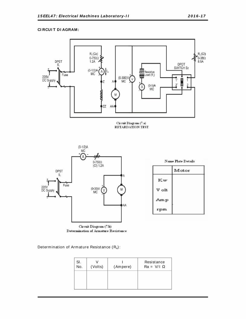
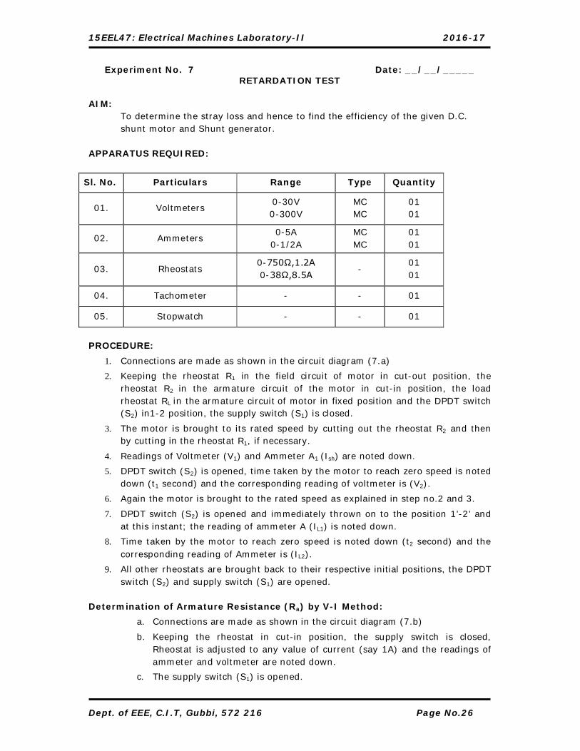
Experiment No. 7 Date: __/__/_____ RETARDATION TEST
AIM:
To determine the stray loss and hence to find the efficiency of the given D.C. shunt motor and Shunt generator.
APPARATUS REQUIRED:
Sl. No. Particulars Range Type Quantity
01. Voltmeters 0-30V 0-300V
MC MC
01 01
02. Ammeters 0-5A
0-1/2A MC MC
01 01
03. Rheostats 0-750Ω,1.2A 0-38Ω,8.5A
- 01 01
04. Tachometer - - 01
05. Stopwatch - - 01
PROCEDURE:
1. Connections are made as shown in the circuit diagram (7.a)
2. Keeping the rheostat R1 in the field circuit of motor in cut-out position, the rheostat R2 in the armature circuit of the motor in cut-in position, the load rheostat RL in the armature circuit of motor in fixed position and the DPDT switch (S2) in1-2 position, the supply switch (S1) is closed.
3. The motor is brought to its rated speed by cutting out the rheostat R2 and then by cutting in the rheostat R1, if necessary.
4. Readings of Voltmeter (V1) and Ammeter A1 (Ish) are noted down.
5. DPDT switch (S2) is opened, time taken by the motor to reach zero speed is noted down (t1 second) and the corresponding reading of voltmeter is (V2).
6. Again the motor is brought to the rated speed as explained in step no.2 and 3.
7. DPDT switch (S2) is opened and immediately thrown on to the position 1’-2’ and at this instant; the reading of ammeter A (IL1) is noted down.
8. Time taken by the motor to reach zero speed is noted down (t2 second) and the corresponding reading of Ammeter is (IL2).
9. All other rheostats are brought back to their respective initial positions, the DPDT switch (S2) and supply switch (S1) are opened.
Determination of Armature Resistance (Ra) by V-I Method:
a. Connections are made as shown in the circuit diagram (7.b)
b. Keeping the rheostat in cut-in position, the supply switch is closed, Rheostat is adjusted to any value of current (say 1A) and the readings of ammeter and voltmeter are noted down.
c. The supply switch (S1) is opened.

15EEL47: Electrical Machines Laboratory-II 2016-17
Dept. of EEE, C.I.T, Gubbi, 572 216 Page No.27
TABULAR COLUMN:
Sl. No
Ish
Amps V1
Volts V2
Volts V=(V1+V2)/2
Volts IL1
Amps IL2
Amps IL=(I1+I2)/2
Amps t1
Sec t2
Sec
Calculation:
V1 = Rated Voltage, Volt.
V2 = Voltage after opening the DPDT switch and at the instant, of 5% reduction in
speed, Volt.
Average Voltage across the load = V = (V1 + V2) / 2 Volt
IL1 = Load current at the instant when DPDT switch is along 1’-2’, Ampere
IL2 = Load current at the instant of 5% reduction in speed, Ampere
IL = (I1 + I2) / 2 Ampere
Total Input = Vr Ir Watt
Power absorbed by the load resistance = W1 = VIL Watt
Stray loss = WS = W1*[t2 / (t1 – t2)] Watt
Efficiency When Working as a Motor:
Aramature current Ia=Ir - Ish --------------------------------------(1)
Armature copper loss = Ia2Ra Watt --------------------------------------(2)
Sl. No.
V (Volts)
I (Ampere)
Resistance Ra = V/I Ω
15EEL47: Electrical Machines Laboratory-II 2016-17
Dept. of EEE, C.I.T, Gubbi, 572 216 Page No.28
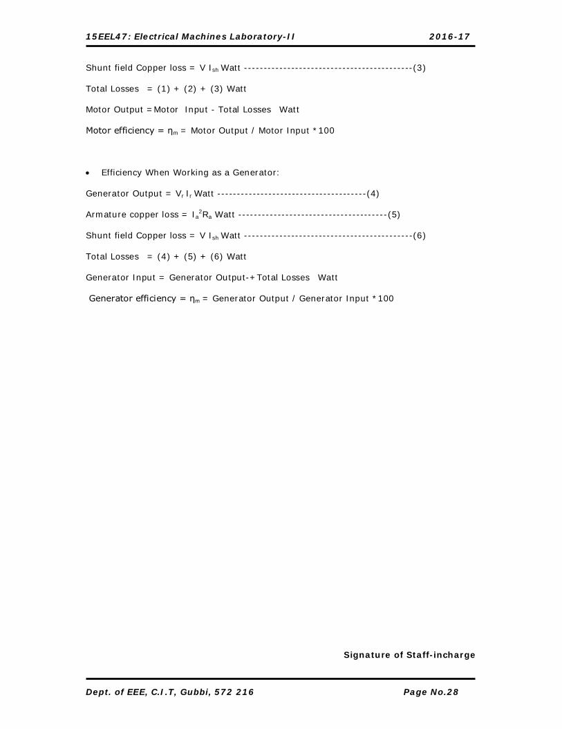
Shunt field Copper loss = V Ish Watt -------------------------------------------(3)
Total Losses = (1) + (2) + (3) Watt
Motor Output =Motor Input - Total Losses Watt
Motor efficiency = ηm = Motor Output / Motor Input *100
Efficiency When Working as a Generator:
Generator Output = Vr Ir Watt --------------------------------------(4)
Armature copper loss = Ia2Ra Watt --------------------------------------(5)
Shunt field Copper loss = V Ish Watt -------------------------------------------(6)
Total Losses = (4) + (5) + (6) Watt
Generator Input = Generator Output-+Total Losses Watt
Generator efficiency = ηm = Generator Output / Generator Input *100
Signature of Staff-incharge

15EEL47: Electrical Machines Laboratory-II 2016-17
CIRCUIT DIAGRAM:
15EEL47: Electrical Machines Laboratory-II 2016-17
Dept. of EEE, C.I.T, Gubbi, 572 216 Page No.30
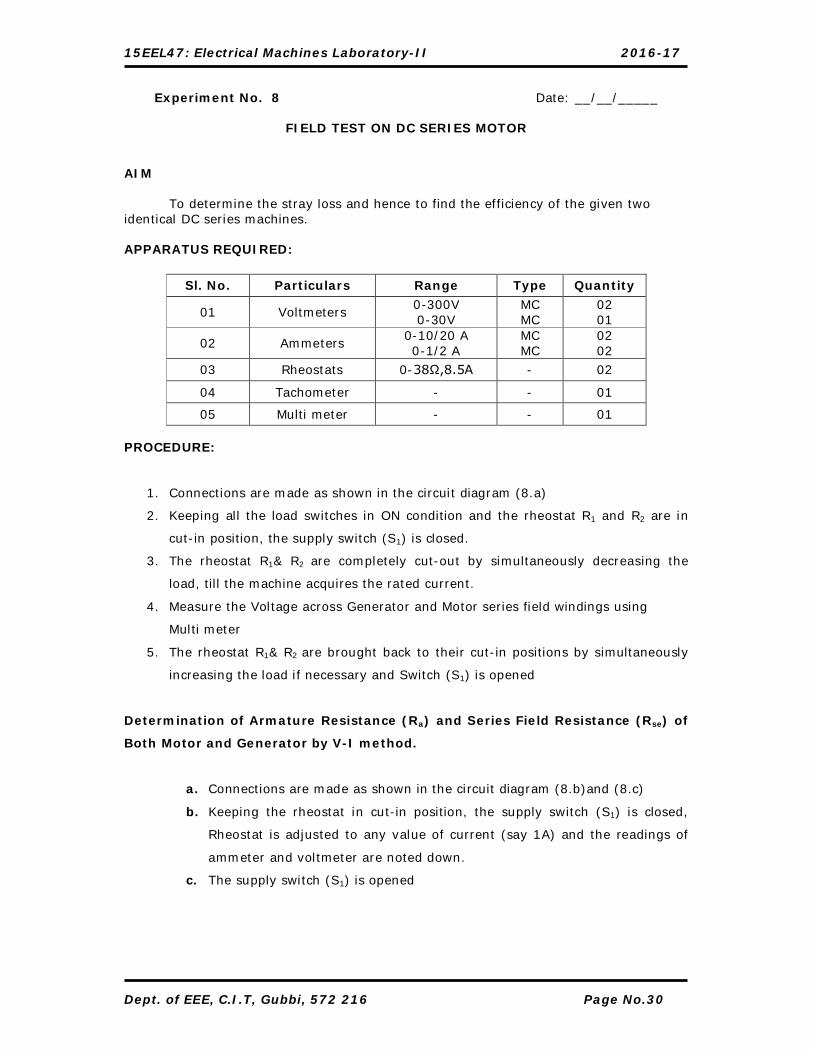
Experiment No. 8 Date: __/__/_____
FIELD TEST ON DC SERIES MOTOR
AIM
To determine the stray loss and hence to find the efficiency of the given two identical DC series machines. APPARATUS REQUIRED:
PROCEDURE:
1. Connections are made as shown in the circuit diagram (8.a)
2. Keeping all the load switches in ON condition and the rheostat R1 and R2 are in
cut-in position, the supply switch (S1) is closed.
3. The rheostat R1& R2 are completely cut-out by simultaneously decreasing the
load, till the machine acquires the rated current.
4. Measure the Voltage across Generator and Motor series field windings using
Multi meter
5. The rheostat R1& R2 are brought back to their cut-in positions by simultaneously
increasing the load if necessary and Switch (S1) is opened
Determination of Armature Resistance (Ra) and Series Field Resistance (Rse) of
Both Motor and Generator by V-I method.
a. Connections are made as shown in the circuit diagram (8.b)and (8.c)
b. Keeping the rheostat in cut-in position, the supply switch (S1) is closed,
Rheostat is adjusted to any value of current (say 1A) and the readings of
ammeter and voltmeter are noted down.
c. The supply switch (S1) is opened
Sl. No. Particulars Range Type Quantity
01 Voltmeters 0-300V 0-30V
MC MC
02 01
02 Ammeters 0-10/20 A 0-1/2 A
MC MC
02 02
03 Rheostats 0-38Ω,8.5A - 02
04 Tachometer - - 01
05 Multi meter - - 01

15EEL47: Electrical Machines Laboratory-II 2016-17
15EEL47: Electrical Machines Laboratory-II 2016-17
Dept. of EEE, C.I.T, Gubbi, 572 216 Page No.32
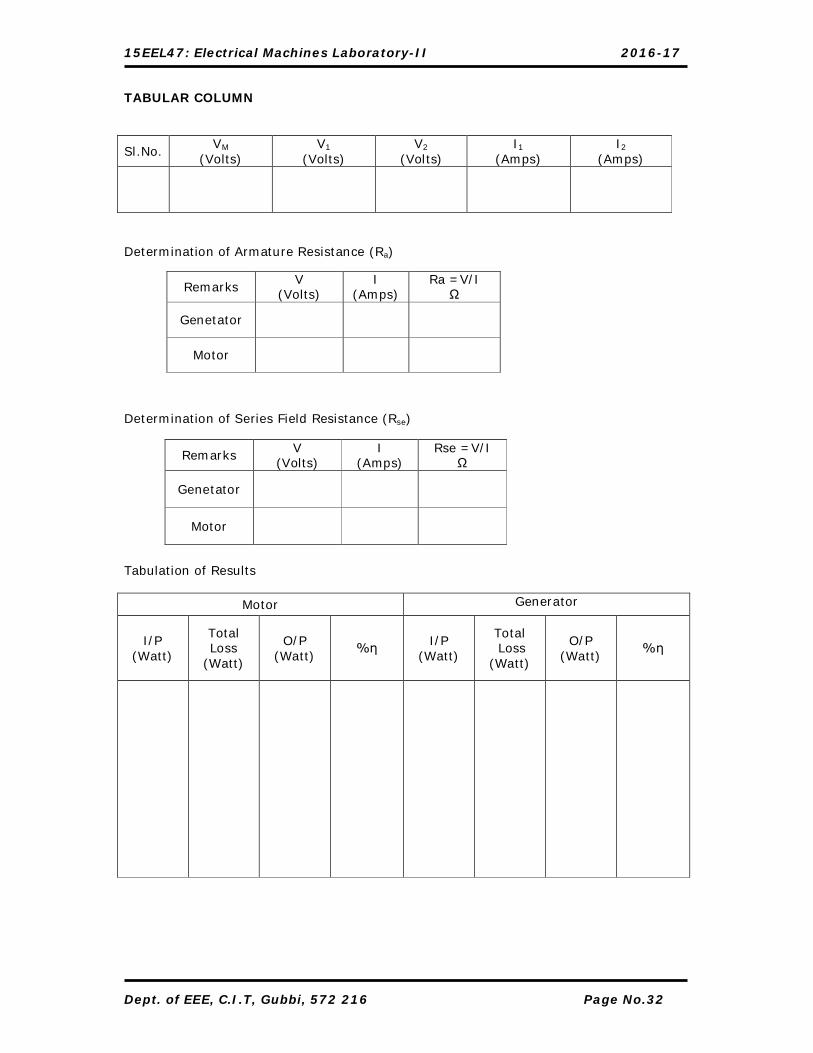
TABULAR COLUMN
Sl.No. VM
(Volts) V1
(Volts) V2
(Volts) I1
(Amps) I2
(Amps)
Determination of Armature Resistance (Ra) Determination of Series Field Resistance (Rse) Tabulation of Results
Motor Generator
I/P (Watt)
Total Loss
(Watt)
O/P (Watt)
%η I/P (Watt)
Total Loss
(Watt)
O/P (Watt)
%η
Remarks V
(Volts) I
(Amps) Ra =V/I
Ω
Genetator
Motor
Remarks V (Volts)
I (Amps)
Rse =V/I Ω
Genetator
Motor

15EEL47: Electrical Machines Laboratory-II 2016-17
CALCULATION: 1. To find the stray loss
Input to the whole set = VMI1 Watt
Output of the Generator = V2I2 Watt
Total Losses of the set; PT = Input – Output
Series field and Armature Copper losses of Motor = I12 (Ra + Rse ) Watt -----(1)
Series field and Armature Copper losses of Generator = I12 Rse + I2
2 Ra ------ (2)
Total Copper Losses of the Set; Pc = (1) + (2) Watt
Stray Loss of the Set; Ws = PT - PC Watt
Stray Loss of each Machine = Ws / 2 Watt
2. Determination of Motor efficiency
Motor Input = (x.V1I1) Watt I1= rated current
Where x= (1, ¾ , ½, ¼ )
Motor Losses = (x.I12 (Ra + Rse ) + Ws / 2 )Watt
Motor Output = (x.V1I1 – (x.I12 (Ra + Rse )) - Ws / 2) Watt
%ηm = O/P / I/P ×100.
.
3. Determination of Generator efficiency
Generator Output = xVrIr Watt Ir= rated current
Where x= (1, ¾ , ½, ¼ )
Generator Losses = x.I2 2 Ra + I1
2Rse+ (Ws / 2) Watt
Generator Input = (xV2I2 + (x.I12 Rse)+ I2
2Ra + Ws / 2) Watt
%ηg = output ×100 Input
Calculation……..

15EEL47: Electrical Machines Laboratory-II 2016-17
Dept. of EEE, C.I.T, Gubbi, 572 216 Page No.34
Signature of Staff-incharge

15EEL47: Electrical Machines Laboratory-II 2016-17
CIRCUIT DIAGRAM
Determination of Armature Resistance (Ra):
Sl.No V (Volts)
I (Ampere)
Resistance Ra = V/I Ω

15EEL47: Electrical Machines Laboratory-II 2016-17
Dept. of EEE, C.I.T, Gubbi, 572 216 Page No.36
Experiment No. 9 Date: __/__/_____ REGENERATIVE TEST
AIM:
To determine the stray loss and hence to find the efficiency of the given two
Identical DC Machines.
APPARATUS REQUIRED:
PROCEDURE:
1. Connections are made as shown in the circuit diagram (9.a)
2. Keeping the rheostat R1 in the field circuit of motor in cut-out position, the rheostat R2 in the armature circuit of the motor and the rheostat R3 in the field circuit of the generator in cut-in positions and the SPST switch in open position, the supply switch (S1) is closed.
3. The motor is brought to its rated speed by cutting out the rheostat R2 and then by cutting in the rheostat R1, if necessary.
4. The excitation of the generator is increased gradually by cutting out the rheostat R3, until the voltmeter connected across the SPST switch reads zero.
5. The SPST switch is closed. Now the generator is connected in parallel with the motor.
6. The generator is overexcited or the motor is under excited by varying their field rheostats. At I2=rated current, the readings of all the meters are noted down.
7. The rheostat R3 (if the motor is under excited vary the rheostat R1) is brought to its initial position, then the SPST switch is opened, all other rheostats are brought back to their respective initial positions, and supply switch (S1) is opened.
Determination of Armature Resistance (Ra) by V-I Method
a. Connections are made as shown in the circuit diagram (9.b)
b. Keeping the rheostat in cut-in position, the supply switch (S1) is closed, Rheostat
is adjusted to any value of current (say 1A) and the readings of ammeter and
Voltmeters are noted down.
c. The supply switch (S1) is opened.
Sl. No. Particulars Range Type Quantity
01 Voltmeters 0-500V 0-300V
MC MC
01 01
02 Ammeters 0-10/20A 0-1/2A
0-5/10 A
MC MC MC
01 02 01
03 Rheostats 0-750Ω,1.2A 0-38,8.5A
- -
02 01
04 Tachometer - - 01

15EEL47: Electrical Machines Laboratory-II 2016-17
CALCULATIONS I. To find stray losses of each machine
Armature copper loss of motor = (I1 + I2 – I3)2 ×Ram Watt -----------------(1)
Field copper loss of motor = V × I3 Watt -----------------------------(2)
Armature copper loss of generator = (I2 + I4)2 ×Rag Watt ----------------------(3) Field copper loss of generator = V × I4 Watt -----------------------------(4)
Total copper losses = (1) + (2) + (3) + (4) Total I/P to the M-G set = V × I1 Watts
Stray losses for both machines = Ws = [(V × I1) - Total copper losses] Watt Therefore Stray loss for each M/C = Ws / 2 Watt
II. Efficiency when working as a motor
I/P to the motor = V (x. Irated ) Watt Where x = (1, 3/4, 1/2, 1/4)
Total losses = (x.Irated - I3)2 × Ram + (V × I3) + (Ws / 2) Watt O/P of motor = (I/P of motor – Total loss) Watt %ηm = (output/ input) ×100
III. Efficiency when working as a generator
O/P of the generator = V (x. Irated )Watt Where x = (1, 3/4, 1/2, 1/4)
Total losses = (x. Irated + I4)2 ×Rag +( V × I4 )+ (Ws / 2)Watt
I/P to the generator = (O/P of the generator + Total losses) Watt % ηg = (output / input) ×100
15EEL47: Electrical Machines Laboratory-II 2016-17
TABULAR COLUMN
Sl. No % ηg % ηm
MODEL GRAPH
Signature of Staff-incharge
15EEL47: Electrical Machines Laboratory-II 2016-17
CIRCUIT DIAGRAM:
Name Plate Details KW
Volt
Amp
RPM

15EEL47: Electrical Machines Laboratory-II 2016-17
Dept. of EEE, C.I.T, Gubbi, 572 216 Page No.40
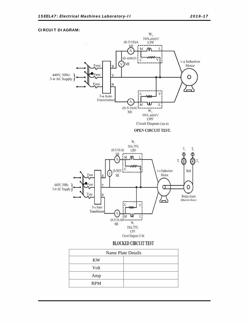
Experiment No. 10 Date: __/__/_____
NO LOAD & BLOCKED ROTOR TEST ON 3-Ф INDUCTION MOTOR
AIM:
To conduct no-load and blocked rotor tests on a given 3-Ф induction motor to
draw the circle diagram and equivalent circuit
APPARATUS REQUIRED:
Sl. No Particulars. Range Type Quantity
01. Voltmeter 0-500V 0-50V
MI MI
01 01
02. Ammeter 0-5/10A MI 02
03 Wattmeter 10A,500V UPF 02
10A,75V UPF 02
PROCEDURE: 1) OPEN CIRCUIT TEST.
1. Connections are made as shown in the circuit diagram (10.a).
2. Keeping the 3-Ф auto-transformer voltage in zero out-put position, the supply
switch (S1) is closed.
3. By varying the 3-Ф auto-transformer, the rated voltage of 3-Ф induction motor is
applied. All the meter readings are noted down.
4. To stop the motor, the 3-Ф auto-transformer is brought back to its initial zero
out-put position, the supply switch (S1) is opened.
2. BLOCKED ROTOR TEST.
1. Connections are made as shown in the circuit diagram (10.b).
2. The brake-drum of the induction motor is blocked from rotation by tightening the
belt.
3. By keeping the 3-Ф auto-transformer voltage in zero out-put position, the supply
switch (S1) is closed.
4. By operating the 3-Ф auto-transformer very slowly, a low voltage is applied, such
that the rated current of the induction motor flows in the stator winding. All the
meter readings are noted down.
5. To stop the motor, the 3-Ф auto-transformer is brought back to its initial zero
out-put position, loosened the belts of brake drum, then open the supply switch
(S1).

15EEL47: Electrical Machines Laboratory-II 2016-17
Dept. of EEE, C.I.T, Gubbi, 572 216 Page No.41
TABULAR COLUMN:
1. OPEN-CIRCUIT TEST.
Sl. No.
V0
(Volts) A1
(Amps) A2
(Amps) I0=(A1+A2)/2
(Amps) W1
(Watt) W2
(Watt) W0=(W1+ W2)
(Watt)
NOTE: 1 W1 = (k1 × Watt Meter Reading.) Where, k1= Deflection Scale Full
) CosI(V selsel
W2 = (k1 × Watt Meter Reading.) Where, k2= Deflection Scale Full
) CosI(V selsel
2. SHORT-CIRCUIT TEST. Sl. No.
VSC
(Volts) A1
(Amps) A2
(Amps) ISC=(A1+A2)/2
(Amps) W1
(Watt) W2
(Watt) WSC=(W1+ W2)
(Watt)
NOTE: W1 = (k1 × Watt Meter Reading.) Where, k1 = Deflection Scale Full
) CosI(V selsel
W2 = (k2 × Watt Meter Reading.) Where, k2 = Deflection Scale Full
) CosI(V selsel

15EEL47: Electrical Machines Laboratory-II 2016-17
Dept. of EEE, C.I.T, Gubbi, 572 216 Page No.42
CONSTRUCTION OF CIRCLE DIAGRAM:
1. Proper scale (I e 1 cm = _________ Amps) is selected.
2. Vector OO! Representing the no-load current I0 is drawn at an angle Ф0 with
respect to Y-axis.
3. At point O', a line O'X' is drawn parallel to X- axis.
4. Vector OA representing ISN is drawn at an angle ФSC with respect to Y-axis.
5. Vector O'A is joined, which represents the out-put line.
6. The out-put line O'A is bisected as follows;
a) With O' as center, radius more than half of O'A, draw an arc on either
side of O'A.
b) Similarly with A as center and same radius an arc is drawn on either
side of O'A.
c) The intersections of the arcs on either side of O’A are joined. This line
gives the perpendicular bisector.
7. Let the perpendicular bisector cuts the horizontal through O'X’ at point C.
8. With C as center O'C as radius, a semi circle is drawn, which passes through point
A.
9. From point A, a perpendicular line AB is drawn to X-axis, thus the vertical line AB
represents power I/P at short circuit ie WSN.
10. Power scale = Cmin AB
WSN Watt/cm.
11. Now point D is located on AB, such that (To draw torque line)
LossCopper Stator LossCopper Rotor
= 1
12. OD is joined which represents torque line.
Now, AD = Rotor copper loss, Watt
DE = Stator copper loss, Watt
EB = Constant loss, Watt
13. Determination of operating point at rated HP:
14. Out-put of motor = HP735.5 Watt.
15. Point F is located on AB extended such that
AF = ScalePower
735.5 HP
16. At point F a parallel line is drawn to the out-put line, which meets the semi-circle
at point P.
17. At point P a perpendicular line to X-axis is drawn cutting the out-put and torque
lines at R and S.

15EEL47: Electrical Machines Laboratory-II 2016-17
18. OP represents the full load current.
15EEL47: Electrical Machines Laboratory-II 2016-17
Dept. of EEE, C.I.T, Gubbi, 572 216 Page No.44
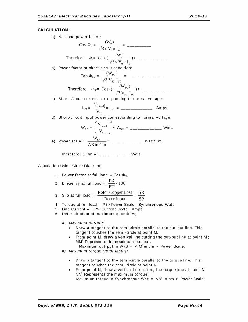
CALCULATION:
a) No-Load power factor:
Cos Φ0 = 00
0
IV3)(W
= __________
Therefore Φ0= Cos! (00
0
IV3)(W
)= ____________
b) Power factor at short-circuit condition:
Cos ΦSC = CSC
SC
.IV.3)(W
S
= ____________
Therefore ΦSC= Cos! ( CSC
SC
.IV.3)(W
S
)= ____________
c) Short-Circuit current corresponding to normal voltage:
ISN = SC
SC
Rated IV
V = _____________ Amps.
d) Short-circuit input power corresponding to normal voltage:
WSN = SC
2
SC
Rated WV
V
= _____________ Watt.
e) Power scale = Cmin AB
WSN = _____________ Watt/Cm.
Therefore; 1 Cm = _____________ Watt.
Calculation Using Circle Diagram:
1. Power factor at full load = Cos ФFL
2. Efficiency at full load = 100PUPR
3. Slip at full load = InputRotor
LossCopper Rotor =
SPSR
4. Torque at full load = PSPower Scale, Synchronous-Watt 5. Line Current = OP Current Scale, Amps 6. Determination of maximum quantities;
a. Maximum out-put: Draw a tangent to the semi-circle parallel to the out-put line. This
tangent touches the semi-circle at point M. From point M, draw a vertical line cutting the out-put line at point M!;
MM! Represents the maximum out-put. Maximum out-put in Watt = M M! in cm Power Scale.
b) Maximum torque (rotor input):
Draw a tangent to the semi-circle parallel to the torque line. This tangent touches the semi-circle at point N.
From point N, draw a vertical line cutting the torque line at point N!; NN! Represents the maximum torque.
Maximum torque in Synchronous Watt = NN! In cm Power Scale.

15EEL47: Electrical Machines Laboratory-II 2016-17
EQUIVALENT CIRCUIT:
CALCULATIONS: Wo = 3 VoIo Cos Φo
Cos Φo =IoVo3
(Wo)
= __________
Z0 = Vo/√3Io
R0 = Vo/√3Ie
Ie = Io Cos Φo
Im = Io Sin Φo
X0 =
mI3V
Ω
Calculations for blocked rotor test:
Short circuit power factor Cos Φsc = IscVsc3
Wsc
Input power on short circuit Ps = 3 I2 R01 (I= Phase current)
Resistance per phase as referred to stator R01= scI3
Wsc2
Motor equivalent impedance per phase as referred to stator Z01= Vsc/√3Isc

15EEL47: Electrical Machines Laboratory-II 2016-17
Dept. of EEE, C.I.T, Gubbi, 572 216 Page No.46
Reactance per phase
X01 = 201
201 RZ Ω
R21 = R01 (Assuming)
We consider X1=Xi
2 hence X1=Xi2=X01/2
The efficiency of the induction motor can be calculated as Power input = out put + losses Losses = Wo + 3 I2 Ro1 Power output = 3I2
.RL I = Load current.
RL = variable load resistance
Efficiency = 100inputpower
outputpower
= 100W.I
i
sc LR
Signature of Staff-incharge

15EEL47: Electrical Machines Laboratory-II 2016-17
CIRCUIT DIAGRAM:

15EEL47: Electrical Machines Laboratory-II 2016-17
Dept. of EEE, C.I.T, Gubbi, 572 216 Page No.48
Experiment No. 11 Date: __/__/_____
V AND Λ CURVES OF SYNCHRONOUS MOTOR
AIM
To obtain V and Λ curves of synchronous motor.
APPARATUS REQUIRED:
Sl. No. Particulars Range Type Quantity
01 Voltmeter 0 –300 V MC 01
02 Ammeters 0-10/20A 0-10/20A 0- 1/2 A
MC MI
MC
01 02 01
03 Rheostats 0-750Ω,1.2A - 02
04 Watt meters 0-600V, 10/20A
UPF 02
PROCEDURE:
1. Connections are made as shown in the circuit diagram (11.a)
2. The TPDT switch (S4) in 1’ & 2’ position. (The field of the synchronous motor (F and FF) is temporarily shorted).
3. Keeping load switch (S3) open, the both rheostats R1 in the field circuit of synchronous motor in cut-in position and rheostat R2 in the field circuit of generator in cut-in positions, the exciter switch DPST (S2) and supply switch TPST (S1) are closed.
4. The output of the three phase Auto transformer is increased slightly, and the direction of rotation of the motor is observed. If the motor runs in opposite direction of the marked position then bring back the Auto Transformer to Zero position and change any two phases of the supply Terminals.
5. The out-put of the three phase auto-transformer is again increased till the synchronous motor attains 50% of its rated speed, immediately the TPDT (S4) is switch over to 1 & 2 position. And then increase to rated voltage.
6. The excitation of synchronous motor is varied in steps by cutting-out the rheostats R1, at no-load, the readings of all the meters are noted down.
7. The rheostat R1 is brought back to cut-in position and generator voltage is built up to its rated value by gradually cutting out the rheostat R2.
8. The load switch (S3) is closed and the load on the generator is adjusted to any convenient value (Say ¼, ½ or ¾ of the rated load current) and the excitation of synchronous motor is varied in steps by cutting-out the rheostat R1. At each step readings of all the meters are noted down.
(NOTE: The selected load current is kept constant throughout the experiment)
9. The load on generator is gradually removed, the load switch (S3) is opened, all the rheostats are brought back to their respective initial positions, and the TPDT (S4) is opened.
15EEL47: Electrical Machines Laboratory-II 2016-17
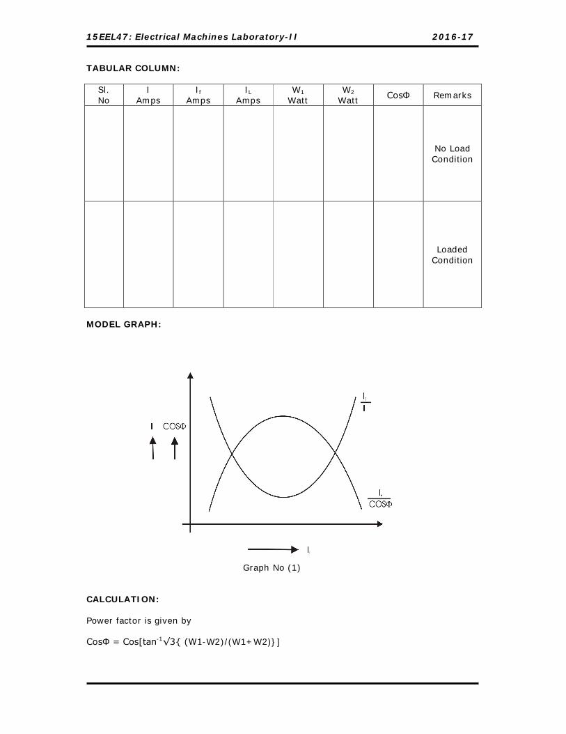
TABULAR COLUMN:
Sl. No
I Amps
If Amps
IL
Amps W1
Watt W2
Watt CosΦ Remarks
No Load Condition
Loaded
Condition
MODEL GRAPH:
Graph No (1)
CALCULATION: Power factor is given by CosФ = Cos[tan-1√3{ (W1-W2)/(W1+W2)}]

15EEL47: Electrical Machines Laboratory-II 2016-17
Dept. of EEE, C.I.T, Gubbi, 572 216 Page No.50
10. The out-put of the 3-phase auto-transformer is brought zero out-put position, then the supply switch (S1) and the exciter switch (S2) is opened.
11. Following graphs are plotted as shown in model graph no (1)
i. Supply current v/s Field current → V curve and
ii. Power factor v/s Field current. → Λ curve.
Signature of Staff-incharge

15EEL47: Electrical Machines Laboratory-II 2016-17
CIRCUIT DIAGRAM:
Name Plate Details KW
Volt
Amp
RPM

15EEL47: Electrical Machines Laboratory-II 2016-17
Dept. of EEE, C.I.T, Gubbi, 572 216 Page No.52
Experiment No. 12 Date: __/__/_____
Equivalent circuit of a 1-phase Induction Motor AIM:
Draw the equivalent circuit of the single phase Induction motor by conducting (a)
No-load test (b) Blocked rotor test.
APPARATUS REQUIRED:
Sl. No Particulars Range Type Quantity
01. Voltmeter 0-300V 0-150V
MI 01
02. Ammeter 0-5/10A MI 01
03. Wattmeter 10A, 300V 10A,150V
UPF 01
04. Tachometer -- Contact Type 01
PROCEDURE: 1) OPEN CIRCUIT TEST.
5. Connections are made as shown in the circuit diagram (12.a).
6. Keeping the 1-Ф auto-transformer voltage in zero out-put position, the supply
switch (S1) is closed.
7. By varying the 1-Ф auto-transformer, the rated voltage of 1-Ф induction motor is
applied. All the meter readings are noted down.
8. To stop the motor, the 1-Ф auto-transformer is brought back to its initial zero
out-put position, the supply switch (S1) is opened.
2. BLOCKED ROTOR TEST.
6. Connections are made as shown in the circuit diagram (12.b).
7. The brake-drum of the induction motor is blocked from rotation by tightening the
belt.
8. By keeping the 1-Ф auto-transformer voltage in zero out-put position, the supply
switch (S1) is closed.
9. By operating the 1-Ф auto-transformer very slowly, a low voltage is applied, such
that the rated current of the induction motor flows in the stator winding. All the
meter readings are noted down.
10. To stop the motor, the 1-Ф auto-transformer is brought back to its initial zero
out-put position, loosened the belts of brake drum, then open the supply switch
(S1).

15EEL47: Electrical Machines Laboratory-II 2016-17
TABULAR COLUMN:
3. OPEN-CIRCUIT TEST.
Sl. No.
V0
(Volts) A
(Amps) W0
(Watt)
NOTE: 1) W = (k × Watt Meter Reading.) Where, k = Deflection Scale Full
) CosI(V selsel
4. SHORT-CIRCUIT TEST.
Sl. No.
Vsc
(Volts) A
(Amps) Wsc
(Watt)
NOTE: 1) W = (k × Watt Meter Reading.) Where, k = Deflection Scale Full
) CosI(V selsel
EQUIVALENT CIRCUIT:
15EEL47: Electrical Machines Laboratory-II 2016-17
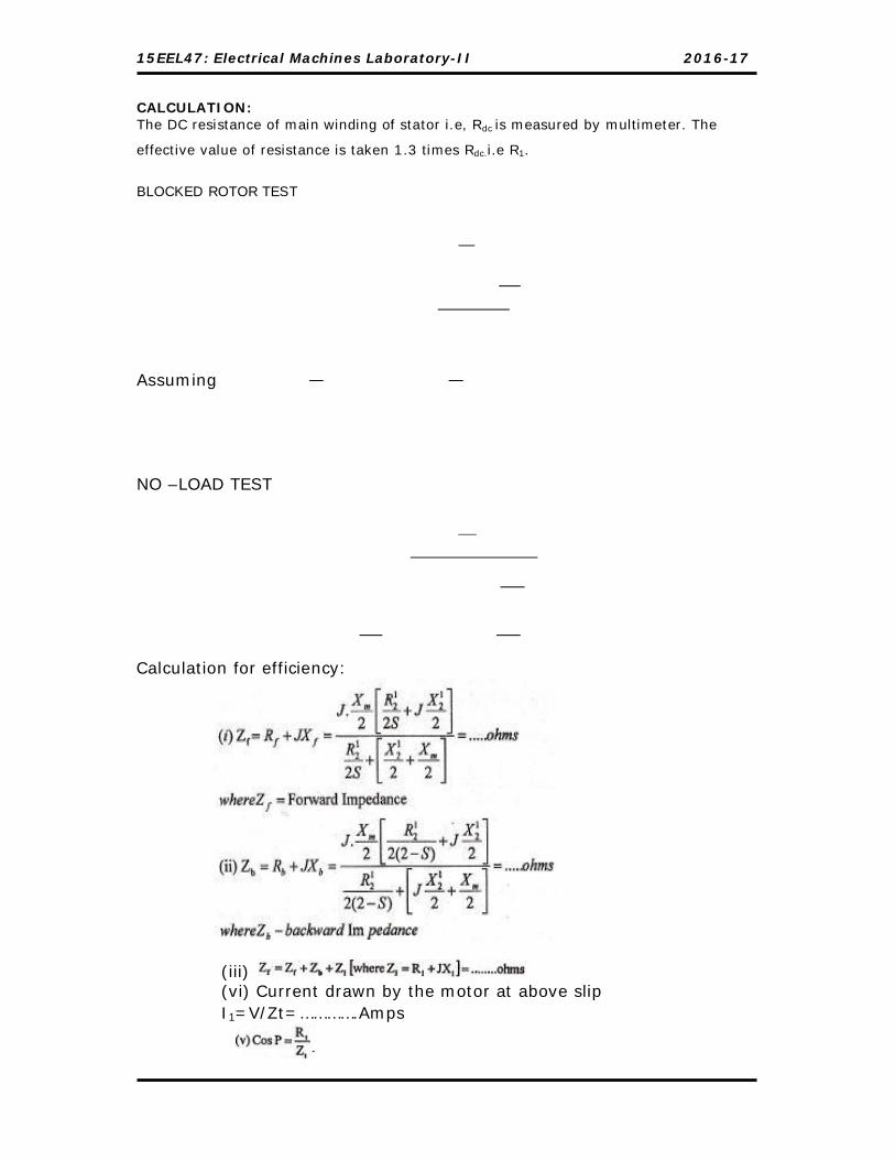
CALCULATION: The DC resistance of main winding of stator i.e, Rdc is measured by multimeter. The
effective value of resistance is taken 1.3 times Rdc.i.e R1.
BLOCKED ROTOR TEST
Assuming
NO –LOAD TEST
Calculation for efficiency:
(iii) (vi) Current drawn by the motor at above slip I1=V/Zt=………….Amps

15EEL47: Electrical Machines Laboratory-II 2016-17
(vi) Voltage across forward rotor = Ef = I1 x Zf = ……….Volts
(viii) Voltage across the backward rotor = Eb = I1 x Zb = .….V

15EEL47: Electrical Machines Laboratory-II 2016-17
Dept. of EEE, C.I.T, Gubbi, 572 216 Page No.56
Signature of Staff-incharge

15EEL47: Electrical Machines Laboratory-II 2016-17
Dept. of EEE, C.I.T, Gubbi, 572 216 Page No.57
QUESTION BANK
1. By conducting suitable experiment, Pre determine the efficiency of the given
DC machine when running as motor for a Load of _____________% by
conducting suitable experiment
2. By conducting suitable experiment, Pre determine the efficiency of the given
DC machine when running as Generator for a load of __________ % by
conducting suitable experiment
3. Draw the Armature Voltage v/s Speed and Field current vs Speed
characteristics of a given DC shunt motor by conducting a necessary Tests.
4. By conducting suitable experiment demonstrate that Speed can be controlled
in both forward and reverse directions for a DC shunt motor.
5. Draw the following Curves for a given DC shunt motor by conducting load
test.
(a) % Efficiency Vs BHP (c) T Vs BHP
(b) N Vs T (d) N Vs BHP
6. Conduct a suitable test on a given DC shunt motor and obtain the following
parameters at __________ % load.
(a) % efficiency (d) N
(b) BHP (e) Motor power input
(c) T Vs BHP
7. Conduct the regenerative test on two similar DC machines and pre-determine
efficiency of a motor at ___________ % load.
8. Conduct the regenerative test on two similar DC machines and pre-determine
efficiency of a generator at __________ % load.
9. Conduct the Back to Back test to pre-determine the efficiency of a motor at
_______ load and efficiency of a generator at _______load.
10.Conduct Retardation Test and predetermine the efficiency as a generator at
_________ Load.
11.Conduct Retardation Test and predetermine the efficiency as a Motor at
_________ Load.
15EEL47: Electrical Machines Laboratory-II 2016-17
Dept. of EEE, C.I.T, Gubbi, 572 216 Page No.58
12.Conduct Retardation Test and predetermine the efficiency as a generator and
as a Motor at _________ Load.
13.Conduct suitable experiment on a 3-phase Synchronous motor to draw ‘V’
curve at no Load.
14.Conduct suitable experiment on a 3-phase Synchronous motor to draw ‘V’
curve at 3A Load.
15.Conduct suitable experiment on a 3-phase Synchronous motor to draw ‘Λ’
curve at no Load.
16.Conduct suitable experiment on a 3-phase Synchronous motor to draw ‘Λ’
curve at 2A Load.
17.Conduct suitable experiment on a 3-phase Synchronous motor to draw ‘V’
and ‘Λ’ curve at No Load.
18.Conduct suitable experiment on a 3-phase Synchronous motor to draw ‘V’
and ‘Λ’ curve at 4A Load.
19.Conduct Field test on a D.C Series Machines and calculate Its Efficiency as a
Motor at __________Load.
20.Conduct Field test on a D.C. Series Machines and calculate Its efficiency, as a
Generator at __________ load.
21.Conduct Field test on a D.C. Series Machines and calculate Its efficiency, as a
Generator and as a Motor at __________ load.
22.Conduct Field test on a D.C. Series Machines, to draw the % efficiency vs
Load curve.
23.Draw the torque VS speed characteristic of a 3 – Phase induction motor by
conducting necessary test on it.
24.Conduct load test on a 3 – Phase induction motor and draw BHP VS η, BHP VS
P.f and BHP VS slip characteristics.
25.Conduct load test on a 3 – Phase induction motor and determine at ¾ full
load slip, η, Torque and output.
26.Conduct necessary tests on a 3 – Phase induction motor and draw its
equivalent circuit.
27.Draw the torque VS speed characteristic of a Single – Phase induction motor
by conducting necessary test on it.

15EEL47: Electrical Machines Laboratory-II 2016-17
Dept. of EEE, C.I.T, Gubbi, 572 216 Page No.59
28.Conduct load test on a Single – Phase induction motor and draw BHP VS η,
BHP VS P.f and BHP VS slip characteristics.
29.Conduct load test on a Single – Phase induction motor and determine at ¾
full load slip, η, Torque and output.
30.Conduct necessary tests on a 3 – Phase induction motor to draw its circle
diagram. Assume stator copper loss is equal to Rotor copper loss.
31.Conduct necessary tests on a 3 – Phase induction motor to draw its circle
diagram and from it determine the following at maximum torque output, η,
slip and power factor.
32.Draw the circle diagram of a 3 – Phase induction motor by conducting
necessary tests and calculate at maximum output, η, slip, power factor and
input current.
33.Draw the circle diagram of a 3 – Phase induction motor and calculate at full
load η, output, slip, torque & P.f.
34.Draw the circle diagram of a 3 – Phase induction motor and calculate at 10
Amps the output, η, slip, torque & Power factor.
35.Conduct necessary test on a given 3 – Phase induction motor and draw
voltage VS speed characteristic.
36.Conduct load test on a given induction generator and find its efficiency at ¾
full load.
37.Conduct load test on a given induction generator and find its efficiency at 5A
load.
38.Determine the efficiency and regulation for three single phase transformers
connected in y-∆ at full load..
15EEL47: Electrical Machines Laboratory-II 2016-17
Dept. of EEE, C.I.T, Gubbi, 572 216 Page No.60
VIVA – VOCE QUESTIONS
1. Load test on Single Phase Induction Motor
1. What are the different types of single phase induction motor?
2. Why a single phase induction motor is not self starting?
3. How do you make a single phase induction motor self starting?
4. Explain briefly the working of split phase induction motor.
5. What are the applications of split phase induction motor?
6. What is the function of capacitor in capacitor start and induction run motor?
7. What are the advantages of capacitor start and capacitor run induction motor?
8. Draw the approximate equivalent circuit for single phase induction motor.
2. Load test on 3- Phase Induction motor
1. What is the basic principle of operation of a 3- phase induction motor?
2. What is the function of Stator?
3. What do you mean by the term Synchronous speed?
4. What is ‘slip’ in Induction motor? Why the slip is never zero in an Induction motor?
5. What is the frequency of induced current in the rotor of an induction motor at stand still and while it is running?
6. Mention the different types of Rotors?
7. What are the differences in construction between Squirrel- cage and Phase wound- rotor of an Induced Motor? What are their applications?
8. Why the rotor bars of a squirrel cage rotor are skewed?
9. What is the advantage of phase wound rotor?
10. How torque is produced in an induction motor?
11. How the starting torque of phase wound rotor does is improved?
12. What is the condition for maximum starting torque? and maximum torque under running condition?
13. Draw the torque slip characteristics and explain.
14. What do you mean by Pullout or Break down torque?
5. Circle Diagram of 3- phase Induction motor
1. What are the losses taking place in 3- phase induction motor?
2. How much operating characteristics of a three phase Induction motor can be computed by use of circle diagram?

15EEL47: Electrical Machines Laboratory-II 2016-17
Dept. of EEE, C.I.T, Gubbi, 572 216 Page No.61
3. What are the losses taking place in a three phase induction motor?
4. How do you determine the friction and windage loss from no-load test?
5. How do you determine the maximum output and minimum torque from circle diagram?
6. What is the expression for rotor copper loss?
7. What do you mean by Synchronous Watt?
8. Draw an approximate equivalent circuit for 3- phase induction motor. Draw the vector diagram.
9. What are the similarities between a transformer and a 3- phase induction motor?
10. What do you mean by “Crawling and Cogging”?
5. Induction Generator
1. What do you understand the floating conditions.
2. What is the use of three phase Energy meter?
3. Explain the meaning of excitation.
6. DC Machines
1. Why should the field rheostat be kept in the position of minimum resistance?
2. What is the loading arrangement used in a DC motor?
3. How can the direction of rotation of a DC shunt motor be reversed?
4. What are the mechanical and electrical characteristics of a DC shunt motor?
5. What are the applications of a DC shunt motor?
6. What is meant by armature reaction?
7. How should a generator be started?
8. How should a Shunt or compound generator be started?
9. When a generator loses its residual flux due to short circuit, how can it be made to build up?
10. What causes heating of armature?
11. What will happen if both the currents are reversed?
12. What will happen if the field of a DC shunt motor is opened?
13. What happens if the direction of current at the terminals of series motor is reversed?

15EEL47: Electrical Machines Laboratory-II 2016-17
Dept. of EEE, C.I.T, Gubbi, 572 216 Page No.62
14. Explain what happens when a DC motor is connected across an AC supply?
15. Why does a DC motor sometimes spark on light load?
16. A DC motor fails to start when switched on. What could be the possible reasons and remedies?
17. What is meant by back?
18. Discuss different methods of speed control of a DC motor.
19. Why a DC series motor should not be started at No load?
20. What are the losses that occur in DC machines?
21. State some present day uses of DC machines.
22. Why a DC series motor should never be stared without load?
23. Why a DC series motor has a high starting torque?
24. Compare the resistances of the field windings of DC shunt and series motor?
25. What are the applications of DC series motor?
26. Comment on the Speed – Torque characteristics of a DC series motor.
27. How does the torque vary with the armature current in a DC series motor?
28. How does the speed of a DC shunt motor vary with armature voltage and field current?
29. Compare the resistance of the armature and field winding.
30. What is the importance of speed control of DC motor in industrial applications?
31. Which is of the two methods of speed control is better and why?
32. Why is the speed of DC shunt motor practically constant under normal load condition?
33. What are the factors affecting the speed of a DC shunt motor?
34. What is meant by residual magnetism?
35. What is critical field resistance?
36. What is meant by saturation?
37. What is the difference between external and internal characteristics?
38. What is the purpose of Swinburne’s test?

15EEL47: Electrical Machines Laboratory-II 2016-17
Dept. of EEE, C.I.T, Gubbi, 572 216 Page No.63
39. What are the constant losses in a DC machine?
40. What are the assumptions made in Swinburne’s test?
41. Why is the indirect method preferred to the direct loading test?
42. The efficiency of DC machine is generally higher when it works as a generator than motor. Is this statement true or false? Justify your answer with proper reasons
43. What is the purpose of Hopkinson’s test?
44. What are the precautions to be observed in this test?
45. What are the advantages of Hopkinson’s test?
46. What are the conditions for conducting the test?
47. Why the adjustments are done in the field rheostat of generator and motor?
48. If the voltmeter across the SPST switch reads zero what does it indicate? If it does not read zero value what does it indicate?
49. What are the other names for Hopkinson’s test?
50. Why is armature resistance less than field resistance of dc shunt machine?
51. Why is armature resistance more than field resistance of dc series machine?
52. Write the EMF equation of DC and AC machine.
53. Write the torque equation of DC motor.
15EEL47: Electrical Machines Laboratory-II 2016-17
Dept. of EEE, C.I.T, Gubbi, 572 216 Page No.64
References
1. Electric Machinery by A. E. Fitzgerald, Charles Kingsley Jr. & Stephen Umans
2. Electric Machinery and Transformers (The Oxford Series in Electrical and Computer Engineering) by Bhag S. Guru and Hüseyin R. Hiziroglu (Jul 20, 2000)
3. The performance and design of alternating current machines BY M.G.SAY, Third
Edition, CBS Publishers & Distributors
4. Transformers by BHEL, Bhopal (MP) TATA MCGRAW HILL.
5. Electrical Machinery by Dr.P.S.Bimbhra, Kanna Publisher
6. Theory of Alternating Current Machinery, Alexander S. Langsdorf TATA MCGRAW
HILL.
7. Electrical Technology Volume – II, by B.L.THERAJA, S Chand Publication.
8. www.bhel.com
9. www.ijems-world.com
10. www.ieeexplore.ieee.org

15EEL47: Electrical Machines Laboratory-II 2016-17
Dept. of EEE, C.I.T, Gubbi, 572 216 Page No.65
Appendix
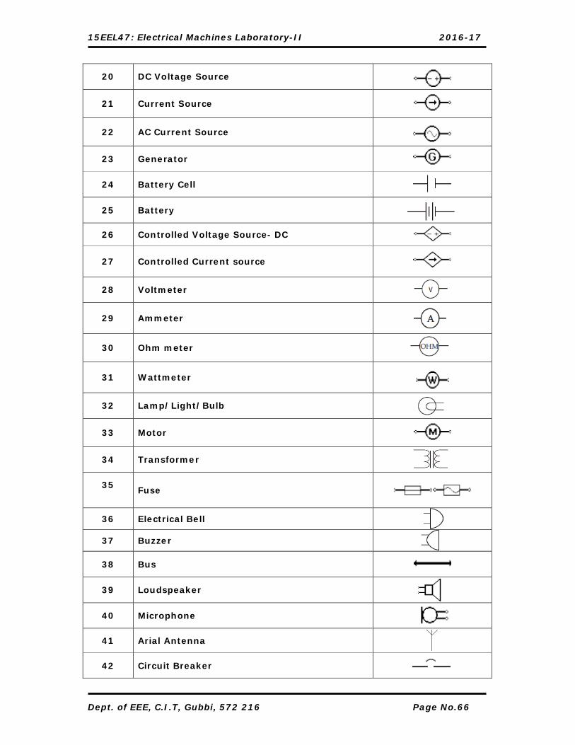
STUDY OF ELECTRICAL SYMBOLS
Sl. No. Particulars Symbol
1 Electrical wire
_______
2 Connected wires
3 Not connected wires
4 SPST Toggle switch
5 SPDT Toggle switch
6 Pushbutton Switch (N.O)
7 Pushbutton Switch (N.C)
8 Earth Ground
9 Chassis ground
10 SPST Relay
11 SPDT Relay
12 Digital Grounding
13 Resistor
14 Potentiometer
15 Variable Resistor
16 Polarized Capacitor
17 Inductor
18 Iron-core Inductor
19 Variable Inductor
15EEL47: Electrical Machines Laboratory-II 2016-17
Dept. of EEE, C.I.T, Gubbi, 572 216 Page No.66
20 DC Voltage Source
21 Current Source
22 AC Current Source
23 Generator
24 Battery Cell
25 Battery
26 Controlled Voltage Source- DC
27 Controlled Current source
28 Voltmeter
29 Ammeter
30 Ohm meter
31 Wattmeter
32 Lamp/Light/Bulb
33 Motor
34 Transformer
35
Fuse
36 Electrical Bell
37 Buzzer
38 Bus
39 Loudspeaker
40 Microphone
41 Arial Antenna
42 Circuit Breaker

15EEL47: Electrical Machines Laboratory-II 2016-17
Dept. of EEE, C.I.T, Gubbi, 572 216 Page No.67
43 Contacts Closed – NC
44 Contacts Open - NO
45 AC Generator
46 DC Generator
47 Relay with Transfer Contacts
48 Current Transformer
49 Loud Speaker
50 Heater
51 DPST
52 DPDT
53 Relay with Contacts
54 Thermistor
55 Full wave, Bridge Type Rectifier
56 Inductor Solenoid / Coil
57 DC Motor
58 AC Motor
59 Galvanometer
60 VAR Meter
61 Power-Factor Meter
62 Isolation Transformer
63 Variable Voltage Transformer

15EEL47: Electrical Machines Laboratory-II 2016-17
Dept. of EEE, C.I.T, Gubbi, 572 216 Page No.68
64 Auto Transformer
65 Current Transformer with Two Secondary Windings On One Core
66 Motor Operated Valve
67 Electrical Distribution Panel
68 Junction Box
69 Instrument Panel or Box
70 Lightning Arrestor
71 Lighting Rod
72 Choke
73 One-way switch
74 Two-way switch
75 Intermediate switch
76 Spot light
77 Distribution Board
78 Fan
79 Joint Box
80 Short circuit device
81 Emergency push button
82 Lighting outlet position
83 Lighting outlet on wall
84 Connector
85 Light Emitting Diode

15EEL47: Electrical Machines Laboratory-II 2016-17
86 Photo Cell
87 Voltage Indicator capacitive
88 General caution
89 Poisonous sign
90 Radio Activity sign
91 Ionizing radiation sign
92 Non-ionizing radiation sign
93 Biohazard sign
94 Warning sign
95 High voltage sign
96 Magnetic field symbol
97 Chemical weapon symbol
98 Laser hazard sign
99 First Aid
100 Fire Extinguisher