electrical machine design unit3-era
TRANSCRIPT
1
DESIGN OF TRANSFORMERS
Classification:
Based on the number of phases: single or three phase
Based on the shape of the magnetic media: core or shell type
Based on the loading condition: power or distribution type
Design features of power and distribution type transformers:
Power transformer Distribution transformer
1. Load on the transformer will be at or near
the full load through out the period of
operation. When the load is less, the
transformer, which is in parallel with other
transformers, may be put out of service.
1. Load on the transformer does not remain
constant but varies instant to instant over
24 hours a day
2. Generally designed to achieve maximum
efficiency at or near the full load. Therefore
iron loss is made equal to full load copper
loss by using a higher value of flux density.
In other words, power transformers are
generally designed for a higher value of flux
density.
2. Generally designed for maximum efficiency at
about half full load. In order that the all day
efficiency is high, iron loss is made less by
selecting a lesser value of flux density. In
other words distribution transformers are
generally designed for a lesser value of flux
density.
3. Necessity of voltage regulation does not
arise .The voltage variation is obtained by
the help of tap changers provided generally
on the high voltage side. Generally Power
transformers are deliberately designed for a
higher value of leakage reactance, so that
the short-circuit current, effect of
mechanical force and hence the damage is
less.
3. Since the distributed transformers are located
in the vicinity of the load, voltage regulation is
an important factor.
Generally the distribution transformers are not
equipped with tap changers to maintain a
constant voltage as it increases the cost,
maintenance charges etc., Thus the
distribution transformers are designed to have
a low value of inherent regulation by keeping
down the value of leakage reactance.
[ Note : Percentage regulation = I1Rp Cosφ ± I1Xp Sinφ x 100 is less when the value of leakage
V1
Reactance Xp is less, as the primary current I1 is fixed & resistance of the transformer Rp is almost
negligible. Ideal value of regulation is zero. ]
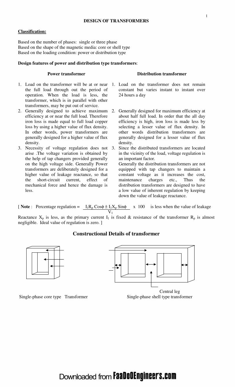
Constructional Details of transformer
Outer leg
Central leg
Single-phase core type Transformer Single-phase shell type transformer

2
RR
3 phase, 3 leg or limb, core type five limb, three phase core type transformer
Transformer [As the size of the transformer increases transportation
difficulties arises because of rail or road gauges. To reduce
the height of the transformer, generally a 5-limb core
is used.]
Three phase shell type transformer
Winding arrangement
LV LV LV HV HV LV LV HV HV LV LV HV
LV to HV Packing material Insulation between Insulation between
HV to LV core and coil LV and HV
Primary Secondary
Unless otherwise specified, LV winding is always placed next to the core and HV winding over
the LV winding in order to reduce the quantity of insulation used, avoid the possibility of breakdown of
the space between the core and HV coil in case HV coil is provided next to the core and to control the
leakage reactance. However in case of transformers where the voltage rating is less, LV and HV windings
can be arranged in any manner.
SPECIFICATION
1. Output-kVA
2. Voltage-V1/V2 with or without tap changers and tapings
a a a
1 2 3 4 5
R Y B
LV HV

3
3. Frequency-f Hz
4. Number of phases – One or three
5. Rating – Continuous or short time
6. Cooling – Natural or forced
7. Type – Core or shell, power or distribution
8. Type of winding connection in case of 3 phase transformers – star-star, star-delta, delta-delta,
delta-star with or without grounded neutral
9. Efficiency, per unit impedance, location (i.e., indoor, pole or platform mounting etc.),
temperature rise etc.,
SIZE OF THE TRANSFORMER
As the iron area of the leg Ai and the window area Aw = (height of the window Hw x Width of the
window Ww) increases the size of the transformer also increases. The size of the transformer increases as
the output of the transformer increases.
Aw
Ai
NOTE:
1. Nomenclature:
V1 – Applied primary voltage
V2 – Secondary terminal voltage
E1, E2 – EMF induced in the primary and secondary windings per phase in case of 3 phase
T1, T2 – Number of primary and secondary turns per phase in case of 3 phase
I1, I2 – Primary and Secondary currents per phase in case of 3 phase
a1, a2 – Cross-sectional area of the primary and secondary winding conductors
δ - Current density in the transformer conductor. Assumed to be same for both LV and HV
winding.
φm – Maximum value of the (mutual or useful) flux in weber = AiBm
Bm – Maximum value of the flux density = φm / Ai tesla
Ai – Net iron area of the core or leg or limb = KiAg
Ki – Iron or stacking factor = 0.9 approximately
Ag – Gross area of the core
2. 1
2
2
1
2
1
2
1
I
I
T
T
E
E
V
V===
a. It is clear that V1I1 = V2I2 or volt-ampere input is equal to volt-ampere output or kVA rating of both
primary and secondary windings is same.
b. It is clear that I1T1 = I2T2 or primary mmf is equal to secondary mmf.
c. It is clear that E1/T1 = E2/T2 or volt/turn of both primary and secondary is same.
2. Window space factor Kw Window space factor is defined as the ratio of copper area in the window to the area of the
window. That is
Area of copper in the window Acu
Kw = < 1.0
Area of the window Aw
For a given window area, as the voltage rating of the transformer increases, quantity of insulation
in the window increases, area of copper reduces. Thus the window space factor reduces as the voltage
increases. A value for Kw can be calculated by the following empirical formula.
10
Hw
Ww
4
Kw = where kVhv is the voltage of the high voltage winding expressed in kV.
30 + kVhv
OUTPUT EQUATIONS
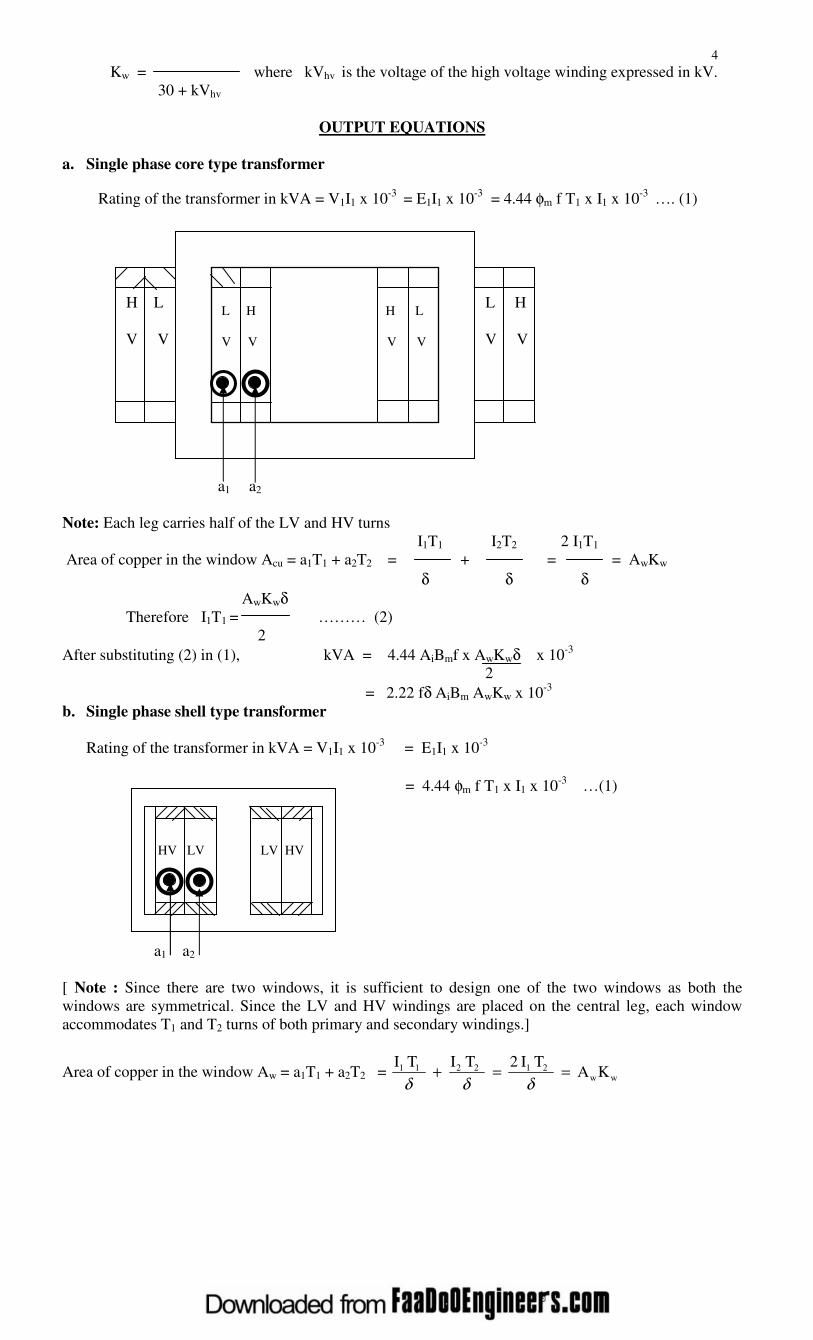
a. Single phase core type transformer
Rating of the transformer in kVA = V1I1 x 10-3
= E1I1 x 10-3
= 4.44 φm f T1 x I1 x 10-3
…. (1)
H L L H
V V V V
a1 a2
Note: Each leg carries half of the LV and HV turns
I1T1 I2T2 2 I1T1
Area of copper in the window Acu = a1T1 + a2T2 = + = = AwKw
δ δ δ
AwKwδ
Therefore I1T1 = ……… (2)
2
After substituting (2) in (1), kVA = 4.44 AiBmf x AwKwδ x 10-3
2
= 2.22 fδ AiBm AwKw x 10-3
b. Single phase shell type transformer
Rating of the transformer in kVA = V1I1 x 10-3
= E1I1 x 10-3
= 4.44 φm f T1 x I1 x 10-3
…(1)
a1 a2
[ Note : Since there are two windows, it is sufficient to design one of the two windows as both the
windows are symmetrical. Since the LV and HV windings are placed on the central leg, each window
accommodates T1 and T2 turns of both primary and secondary windings.]
Area of copper in the window Aw = a1T1 + a2T2 = ww212211 KA T I 2
T I
T I
==+δδδ
L H H L
V V V V
HV LV
LV HV

5
Therefore I1T1 = AwKwδ …. (2)
2
After substituting (2) in (1) kVA = 4.44 AiBmf x AwKwδ x 10-3
2
= 2.22 f δ AiBm AwKw x 10-3
c. Three phase core type transformer
Rating of the transformer in kVA = V1I1 x 10-3
= E1I1 x 10-3
= 3 x 4.44 φm f T1 x I1 x 10-3
…(1)
[Note: Since there are two windows, it is sufficient to design one of the two windows, as both the
windows are symmetrical. Since each leg carries the LV &HV windings of one phase, each window
carry the LV & HV windings of two phases]
Since each window carries the windings of two phases, area of copper in the window, say due to R & Y
phases
Acu = (a1T1 + a2T2) + (a1T1 + a2T2)
= 2(a1T1 + a2T2) = 2( I1T1 + I2T2)
δ δ = 2 x 2 I1T1 = Aw Kw
δ
Therefore I1T1 = AwKw δ …. (2)
4
After substituting (2) in (1)
kVA = 3 x 4.44 AiBmf x AwKwδ x 10-3
= 3.33 f δ AiBm AwKw x 10-3
2
d. Three phase shell type transformer
R
Rating of the transformer in kVA = 3V1I1 x 10-3
= 3E1I1 x 10-3
= 3 x 4.44 φm f T1 x I1 x 10-3
…(1)
Y
B
[ Note: Since there are six windows, it is sufficient to design one of the six windows, as all the windows
are symmetrical. Since each central leg carries the LV and HV windings of one phase, each window
carries windings of only one phase.]
Since each window carries LV and HV windings of only one phase,
R Y
H
L H
V V
H L
V V
H L
V V
L H
V V
H L
V V
L H
V V

6
Area of copper in the window Aw = a1T1 + a2T2 = I1T1 + I2T2
δ δ = 2 I1T1 = AwKw
δ
Therefore I1T1 = AwKw δ …. (2)
2
Substituting (2) in (1),
kVA = 3 x 4.44 AiBmf x AwKwδ x 10-3
2
= 6.66 f δ AiBm AwKw x 10-3
Usual values of current and Flux density:
The value of current density depends on the type of cooling-natural or forced. Upto 25000KVA
natural cooling is adopted in practice. The current density lies between 2.0 and 3.2 A/mm2 for natural
cooling and between 5.3 and 6.4 A/mm2 for forced cooling.
The flux density lies between 1.1 and 1.4 T in practice.
Note : To solve the output equation, KVA = 2.22 or 3.33 or 6.66 f δ AiBm AwKw x 10-3
having two
unknowns Ai and Aw , volt per turn equation is considered.
Volt / turn equation
Rating of the transformer per phase kVA / ph = V1I1 x 10-3
= E1I1 x 10-3
= 4.44 φm f T1 I1 x 10-3
The term φm is called the magnetic loading and I1T1 is called the electric loading. The required kVA can
be obtained by selecting a higher value of φm and a lesser of I1T1 or vice-versa.
As the magnetic loading increases, flux density and hence the core loss increases and the
efficiency of operation decreases. Similarly as the electric loading increases, number of turns, resistance
and hence the copper loss increases. This leads to reduced efficiency of operation. It is clear that there is
no advantage by the selection of higher values of I1T1 or φm. For an economical design they must be
selected in certain proportion. Thus in practice
φm φm
= a constant Kt or I1T1 = …… (2)
I1T1 Kt
Kt x kVA / ph
Substituting (2) in (1), kVA / ph = 4.44 φm f φm x 10-3
and φm = 4.44f x 10-3
Kt
Since the emf induced E1 = 4.44 φm f T1 is in T1 turns, voltage / turn
Et = E1/T1= 4.44 φm f = 4.44 f Kt x kVA / ph
4.44f x 10-3
= 4.44f x 103 x Kt x kVA / ph = K kVA

7
Where K = 4.44 f x 103 x Kt is another constant and kVA is the rated output of the transformer. The
constant K depends on the type of transformer-single or three phase, core or shell type, power or
distribution type, type of factory organization etc.,
Emperical values of K : ( 1.0 to 1.2) for single phase shell type
1.3 for three-phase shell type (power)
(0.75 to 0.85) for single phase core type
(0.6 to 0.7) for three phase core type (power)
0.45 for three-phase core type (distribution)
Core design
φm
Net iron area of the leg or limb or coreAi = m2
Bm
For a given area Ai, different types of core section that are used in practice are circular, rectangular and
square.
[Note: Choice of core section: 10cm
3.16cm
3.56cm
3.16cm 1.0cm
Circular core Square core Rectangular core
If the area is 10cm2, then for Ai = 10cm
2, side for Ai = 10cm
2 , the
the diameter of the core of the square = 10 perimeter = (10+1)2=22cm if
=3.56cm and the = 3.16 cm and perimeter the sides of the rectangular
Circumference = is 4x3.16=12.64cm are assumed to be 10cm and 1.0cm
πx3.56=11.2 cm
It is clear that the rectangular core calls for more length of copper for the same number of turns as
compared to circular core. Therefore circular core is preferable to rectangular or square core.
Mechanical forces
Circular coil on a Round coil on Square coil on Circular coil on a Rectangular coil
Circular core a square core a square core rectangular core on a rectangular
core
Very high values of mechanical forces under short circuit conditions tries to deform the shape of
the square or rectangular coil (the mechanical forces try to deform to a circular shape) and hence damage
the coil and insulation. Since this is not so in case of circular coils, circular coils are preferable to square
or rectangular coils.
Thus a circular core and a circular coil is preferable. Since the core has to be of laminated type,
circular core is not practicable as it calls for more number of different size laminations and poses the
problem of securing them together is in position. However, a circular core can be approximated to a
stepped core having infinite number of steps. Minimum number of steps one and the number of steps in
practice is limited to a definite number. Whenever a stepped core is employed a circular coil is used.

8
Laminated circular core Stepped core approximated to a circular core
Leg or limb section details: -
The different types of leg sections used are rectangular, square and stepped.
1. Rectangular core (with a rectangular coil)
a = width of the stamping or leg
b = gross thickness of the assembled core or width of the
transformer
b b Ai = net iron area of the leg or limb or core
= a xKi b for a core type transformer
Ki = iron factor or stacking factor
2a = width of the central leg
b = width of the transformer
Ai = 2a x Kib for a shell type transformer
a 2a
Leg of a core type Central leg of a
Transformer shell type transformer
2. (a) Square core (with a square coil)
a = width of the leg
a = width of the transformer
Ai = Kia2 for a core transformer
a 2a = width of the central leg
2a = width of the transformer
a Ai = Ki (2a)2 for a shell type
transformer
(b) Square core (with a circular coil)
a = width of the stamping or leg
= d Sin45 or d Cos45
d a = 0.71d where d is the diameter of the circumscribing
circle
Ai = Kia2 = Ki(0.71d)
2
= 0.9 x 0.5d2 for 10% insulation or Ki = 0.9
= 0.45d2
a
Area of the circumscribing circle Ac = πd2/4 = 0.785d
2
Therefore Ai = 0.45d2 = 0.573
450
9
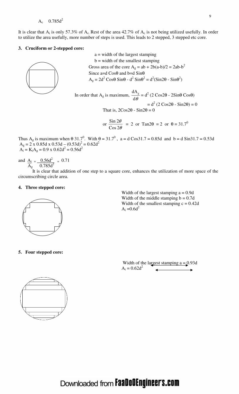
Ac 0.785d2
It is clear that Ai is only 57.3% of Ac. Rest of the area 42.7% of Ac is not being utilized usefully. In order
to utilize the area usefully, more number of steps is used. This leads to 2 stepped, 3 stepped etc core.
3. Cruciform or 2-stepped core:
a = width of the largest stamping
b = width of the smallest stamping
Gross area of the core Ag = ab + 2b(a-b)/2 = 2ab-b2
Since a=d Cosθ and b=d Sinθ
Ag = 2d2 Cosθ Sinθ - d
2 Sinθ2
= d2(Sin2θ - Sinθ2
)
In order that Ag is maximum, θd
dAg= d
2 (2 Cos2θ - 2Sinθ Cosθ)
= d2 (2 Cos2θ - Sin2θ) = 0
That is, 2Cos2θ - Sin2θ = 0
or θθ
2 Cos
2Sin = 2 or Tan2θ = 2 or θ = 31.7
0
Thus Ag is maximum when θ 31.70. With θ = 31.7
0 , a = d Cos31.7 = 0.85d and b = d Sin31.7 = 0.53d
Ag = 2 x 0.85d x 0.53d – (0.53d)2 = 0.62d
2
Ai = KiAg = 0.9 x 0.62d2 = 0.56d
2
and Ai = 0.56d2
= 0.71
Ag 0.785d2
It is clear that addition of one step to a square core, enhances the utilization of more space of the
circumscribing circle area.
4. Three stepped core: Width of the largest stamping a = 0.9d
Width of the middle stamping b = 0.7d
Width of the smallest stamping c = 0.42d
Ai =0.6d2
5. Four stepped core:
Width of the largest stamping a = 0.93d
Ai = 0.62d2
10
Note : As the number of steps increases, the diameter of the circumscribing circle reduces. Though the
cost of the core increases, cost of copper and size of the coil or transformer reduces.
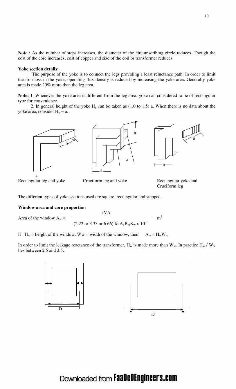
Yoke section details: The purpose of the yoke is to connect the legs providing a least reluctance path. In order to limit
the iron loss in the yoke, operating flux density is reduced by increasing the yoke area. Generally yoke
area is made 20% more than the leg area..
Note: 1. Whenever the yoke area is different from the leg area, yoke can considered to be of rectangular
type for convenience.
2. In general height of the yoke Hy can be taken as (1.0 to 1.5) a. When there is no data about the
yoke area, consider Hy = a.
a
a
b
a
a
a
a
Rectangular leg and yoke Cruciform leg and yoke Rectangular yoke and
Cruciform leg
The different types of yoke sections used are square, rectangular and stepped.
Window area and core proportion
kVA
Area of the window Aw = m2
(2.22 or 3.33 or 6.66) fδ Ai BmKw x 10-3
If Hw = height of the window, Ww = width of the window, then Aw = HwWw
In order to limit the leakage reactance of the transformer, Hw is made more than Ww. In practice Hw / Ww
lies between 2.5 and 3.5.
aa
D
D
11
a OR
b
a
a
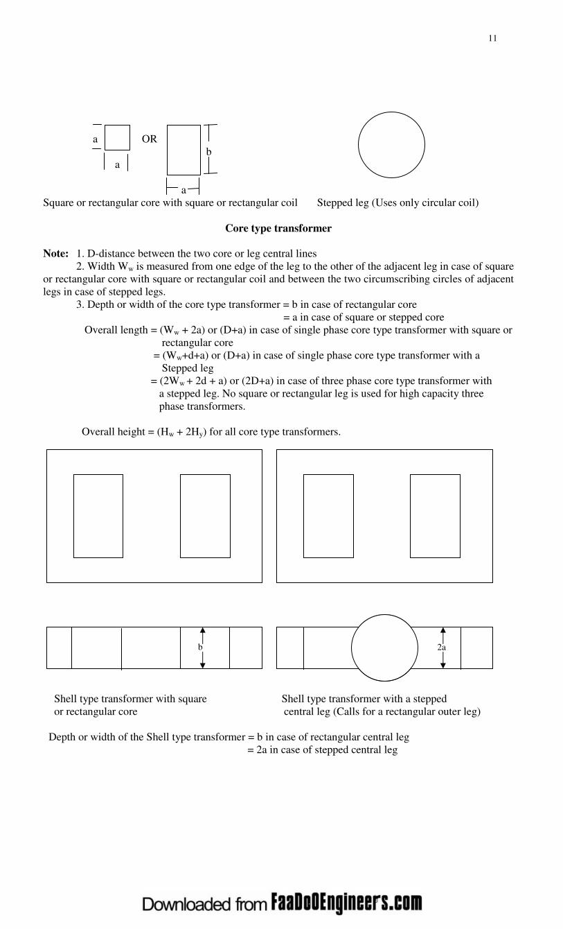
Square or rectangular core with square or rectangular coil Stepped leg (Uses only circular coil)
Core type transformer
Note: 1. D-distance between the two core or leg central lines
2. Width Ww is measured from one edge of the leg to the other of the adjacent leg in case of square
or rectangular core with square or rectangular coil and between the two circumscribing circles of adjacent
legs in case of stepped legs.
3. Depth or width of the core type transformer = b in case of rectangular core
= a in case of square or stepped core
Overall length = (Ww + 2a) or (D+a) in case of single phase core type transformer with square or
rectangular core
= (Ww+d+a) or (D+a) in case of single phase core type transformer with a
Stepped leg
= (2Ww + 2d + a) or (2D+a) in case of three phase core type transformer with
a stepped leg. No square or rectangular leg is used for high capacity three
phase transformers.
Overall height = (Hw + 2Hy) for all core type transformers.
Shell type transformer with square Shell type transformer with a stepped
or rectangular core central leg (Calls for a rectangular outer leg)
Depth or width of the Shell type transformer = b in case of rectangular central leg
= 2a in case of stepped central leg
b
2a

12
Overall length = (2Ww + 4a) in case of a shell type transformer with rectangular or square central
leg
= (d + 2Ww + 2a) in case of shell type transformer with central stepped leg
Overall height = (Hw + 2Hy) in case of a single phase shell type transformer
= 3(Hw+2Hy) in case of a three phase shell type transformer
Winding details:
Since the applied voltage V1 is approximately equal to the voltage induced E1 = 4.44 φm f T1 = Et T1
Number of primary turns (or turns / phase) T1 = V1 / Et in case of single phase transformers
= V1ph / Et in case of 3 phase transformers
Number of secondary turns (or turns / phase) T2 = V2/ Et in case of single phase transformers
= V2ph / Et in case of 3 phase transformers
Primary current (or current/phase) I1 = kVA x 103 / V1 in case of single phase transformers
= kVA x 103 / 3V1ph in case of 3 phase transformers
Cross-sectional area of primary winding conductor a1 = I1/ δ mm2
Secondary current (or current / phase) I2 = kVA x 103 / V2 in case of single phase transformers
= kVA x 103 / 3V2ph in case of 3 phase transformers
Cross-sectional area of secondary winding conductor a2 = I2/ δ mm2
Knowing the number of turns and cross-sectional area of the primary and secondary winding
conductors, number of turns/layer in a window height of Hw and number of layers in a window width of
Ww can be found out.
No-load current of a transformer The no-load current I0 is the vectorial sum of the magnetizing current Im and core loss or working
component current Ic. [Function of Im is to produce flux φm in the magnetic circuit and the function of Ic is
to satisfy the no load losses of the transformer]. Thus,
Io = √ Ic2 + Im
2 ampere.
V1 = - E1
Io Io
Ic
V1 φm
Im
Transformer under no-load condition Vector diagram of Transformer
under no-load condition
No load input to the transformer = V1I0Cosφ0 = V1Ic = No load losses as the output is zero and
input = output + losses.
Since the copper loss under no load condition is almost negligible, the no load losses can entirely be taken
as due to core loss only. Thus the core loss component of the no load current
Ic = 1V
loss core for single phase transformers
φm

13
= ph 1V
phase / loss core for 3 phase transformers.
Magnetizing ampere turns (Max value)
RMS value of magnetizing current Im =
2 T1
with the assumption that the magnetizing current is sinusoidal (which is not true in practice)
The magnetic circuit of a transformer consists of both iron and air path. The iron path is due to
legs and yokes and air path is due to the unavoidable joints created by the core composed of different
shaped stampings. If all the joints are assumed to be equivalent to an air gap of lg , then the total ampere
turns for the transformer magnetic circuit is equal to AT for iron + 800,000lgBm. Therefore,
AT for iron + 800,000lgBm
Im =
2 T1
Note:
1. In case of a transformer of normal design, the no load current will generally be less than about 2% of
the full load current.
2. No load power factor Cosφ0 = Ic/I0 and will be around 0.2.
3. Transformer copper losses:
a) The primary copper loss at no load is negligible as I0 is very less.
b) The secondary copper loss is zero at no load, as no current flows in the secondary winding at no
load.
4. Core or iron loss:
Total core loss = core loss in legs + core loss in yokes.
The core loss can be estimated at design stage by referring to graph of core loss/kg versus flux
density.
Core loss in leg = loss/kg in leg x weight of leg in kg
= loss / kg in leg x volume of the leg (AiHw) x density of steel or iron used
Core loss in yoke = loss/kg in Yoke x volume of yoke (Ay x mean length of the yoke) x density of iron
used
The density of iron or steel used for the transformer core lies between 7.55 to 7.8 grams/cc.
RESISTANCE AND REACTANCE OF TRANSFORMER
Resistance:
Resistance of the transformer referred to primary / phase Rp = rp + rs’ = rp + rs
2
2
1
S
P
2
1
V
Vor
T
Tor
T
T
.
Resistant of the primary winding/phase rp = (ρLmt) Tp ohm
a1
Resistivity of copper at 600C ρ= 2.1 x 10
-6 ohm-cm or 2.1 x 10
-8 ohm-m or 0.021 ohm/m/mm
2
Mean length of turn of the primary winding Lmt P = π x mean diameter of the primary winding
One piece stamping Two piece stamping
Impracticable pre-formed (called for the use of
coils on the legs)
14
Number of primary turns / phase T1 or Tp = V1ph / Et
Resistance of the secondary winding / phase rs = ρLmt Ts
a2
Mean length of turn of the secondary winding Lmt S = π x mean diameter of the secondary winding
Number of secondary turns / phase T2 or Ts = V2ph / Et
Similarly resistance of the transformer referred to secondary / phase Rs = r'p+ rs = rp
2
P
S
T
T
+ rs
Reactance: [Note: 1. Useful flux: It is the flux that links with both primary and secondary windings and is responsible
in transferring the energy Electro-magnetically from primary to secondary side. The path of the useful
flux is in the magnetic core.
2. Leakage flux: It is the flux that links only with the primary or secondary winding and is responsible in
imparting inductance to the windings. The path of the leakage flux depends on the geometrical
configuration of the coils and the neighboring iron masses.
3. Reactance:
a) Leakage reactance = 2πf x inductance = 2πf x Flux linkage / current
b) Flux linkage = flux x number of turns
c) Flux =( mmf or AT) / Reluctance = AT x permeanence ∧
d) Permeanace ∧ = 1 / Reluctance = aµ0µr / l where
a = area over which the flux is established
l = length of the flux path
If x p and xs are the leakage reactances of the primary and secondary windings, then the total leakage
reactance of the transformer referred to primary winding Xp = xp + x '
s = xp+ xs (Tp/Ts)2.
Similarly the leakage reactance of the transformer referred to secondary winding
Xs = x‘p + xs = xp (Ts / Tp )
2 + xs .
Estimation of the leakage flux or reactance is always difficult, on account of the complex
geometry of the leakage flux path and great accuracy is unobtainable. A number of assumptions are to be
made to get a usable approximate expression. Validity or the accuracy of the expression is checked
against test data.
Expression for the leakage reactance of a core type transformer with concentric LV and HV coils of
equal height or length:
Assumptions considered for the derivation:
a. Effect of magnetizing current is neglected.
b. Reluctance and effect of saturation of iron is neglected.
c. All the mmf is assumed to be used to over come the reluctance of coil height
d. Leakage flux distribution in coil and in the space between the LV and HV coils is assumed to be
parallel to the leg axis.
Let,
bp and bs = Radial depth of primary and secondary windings
Tp and Ts = Number of primary and secondary turns per phase for 3 phase
Ip and Is = Primary and secondary currents per phase for 3 phase
Lmt P Lmt S = Mean length of turn of primary or secondary windings respectively

15
Lmt = Mean length of primary and secondary windings considered together
L0 = Circumference of the insulation portion or duct or both between LV and HV coils
Lc = Axial height or length of the both LV and HV coils
The total flux linkage of the primary or secondary winding is due to
a. Leakage flux inside the primary or secondary winding and
b. Leakage flux in between the LV and HV coils
To determine the flux linkage due to the flux inside the coil, consider an elemental strip dx at a distance
‘x’ from the edge of the LV winding (say primary winding). Then the flux linkage of the primary
winding, due to the flux φX in the strip.
ψX = φX x number of turns linked by φX
= ampere turns producing φX permeance of the strip x number of turns linked by φX
= Ip Tpx × Lmt p d x µ0 × Tp x
bp Lc bp
Considering the mean length of the strip is approximately equal to Lmt P .
Therefore, the total flux linkage due to the flux inside the coil
ψ = ∫pb
0
IpT2
p
c
p
2
Pmt 0
L b
L µ x
2 dx = IpT
2
p µ0
c
Pmt
L
L x
3
bP
If one half of the flux 0φ in between the LV and HV windings is assumed to be linking with each
windings, then the flux linkage of the primary winding due to half of the flux φ0 in between LV and HV
windings,
0ψ = 2
1 φ0 x number of turns linked by φ0
= ampere turns producing φ0 x permeance of the duct x number of turns linked by flux φ0 .
= 2
1IpTp x
c
00
L
aL µ x Tp
Therefore total flux linkage of the primary winding = ψ + ψ0 = Ip T2
p µ0 (Lmt p bp + L0a )
Lc 3 2
= IpTp2 µ0 Lmt p ( bp + a ) with the assumption that Lmt p ≈ L0
Lc 3 2
Therefore leakage reactance of the primary / ph
xp = 2πf x flux linkage
Current
= 2πf x IpTp2 µ0 Lmt p ( bp + a )
Lc 3 2
Ip
= 2πf Tp2 µ0 Lmt s ( bp + a ) ohm
Lc 3 2
Similarly leakage reactance of the secondary winding / ph

16
xs = 2πf TS2 µ0 Lmt s ( bS + a ) ohm
Lc 3 2
Therefore leakage reactance of the transformer referred to primary winding per phase
Xp = xp + x '
s = xp + xs ( Tp )2
TS
= 2πf Tp2 µ0 [ Lmt p ( bp + a ) + Lmt s ( bS + a ) ]
Lc 3 2 3 2
= 2πf Tp2 µ0
c
mt
L
L
++ a
3
b
3
bsp
ohm
DESIGN OF TANK AND TUBES
Because of the losses in the transformer core and coil, the temperature of the core and coil
increases. In small capacity transformers the surrounding air will be in a position to cool the transformer
effectively and keeps the temperature rise well with in the permissible limits. As the capacity of the
transformer increases, the losses and the temperature rise increases. In order to keep the temperature rise
with in limits, air may have to be blown over the transformer. This is not advisable as the atmospheric air
containing moisture, oil particles etc., may affect the insulation. To overcome the problem of atmospheric
hazards, the transformer is placed in a steel tank filled with oil. The oil conducts the heat from core and
coil to the tank walls. From the tank walls the heat goes dissipated to surrounding atmosphere due to
radiation and convection. Further as the capacity of the transformer increases, the increased losses
demands a higher dissipating area of the tank or a bigger sized tank. This calls for more space, more
volume of oil and increases the cost and transportation problems. To overcome these difficulties, the
dissipating area is to be increased by artificial means with out increasing the size of the tank. The
dissipating area can be increased by
1. fitting fins to the tank walls 3. fitting tubes to the tank and
2. using corrugated tank 4. using auxiliary radiator tanks
Since the fins are not effective in dissipating heat and corrugated tank involves constructional
difficulties, they are not much used now a days. The tank with tubes are much used in practice. Tubes in
more number of rows are to be avoided as the screening of the tank and tube surfaces decreases the
dissipation. Hence, when more number of tubes are to be provided, a radiator attached with the tank is
considered. For much larger sizes forced cooling is adopted.
DIMENSIONS OF THE TANK
17
185
1 2 3 36
Header
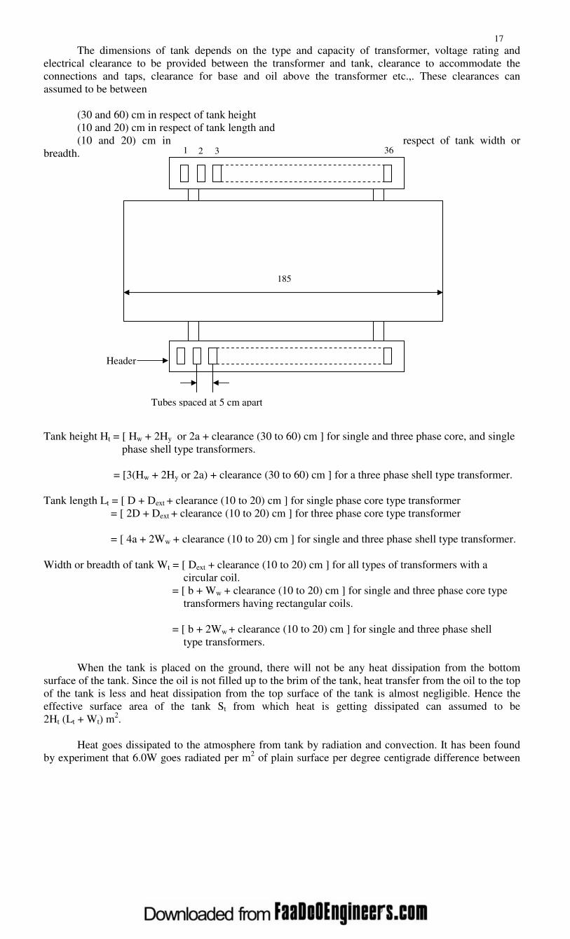
Tubes spaced at 5 cm apart
The dimensions of tank depends on the type and capacity of transformer, voltage rating and
electrical clearance to be provided between the transformer and tank, clearance to accommodate the
connections and taps, clearance for base and oil above the transformer etc.,. These clearances can
assumed to be between
(30 and 60) cm in respect of tank height
(10 and 20) cm in respect of tank length and
(10 and 20) cm in respect of tank width or
breadth.
Tank height Ht = [ Hw + 2Hy or 2a + clearance (30 to 60) cm ] for single and three phase core, and single
phase shell type transformers.
= [3(Hw + 2Hy or 2a) + clearance (30 to 60) cm ] for a three phase shell type transformer.
Tank length Lt = [ D + Dext + clearance (10 to 20) cm ] for single phase core type transformer
= [ 2D + Dext + clearance (10 to 20) cm ] for three phase core type transformer
= [ 4a + 2Ww + clearance (10 to 20) cm ] for single and three phase shell type transformer.
Width or breadth of tank Wt = [ Dext + clearance (10 to 20) cm ] for all types of transformers with a
circular coil.
= [ b + Ww + clearance (10 to 20) cm ] for single and three phase core type
transformers having rectangular coils.
= [ b + 2Ww + clearance (10 to 20) cm ] for single and three phase shell
type transformers.
When the tank is placed on the ground, there will not be any heat dissipation from the bottom
surface of the tank. Since the oil is not filled up to the brim of the tank, heat transfer from the oil to the top
of the tank is less and heat dissipation from the top surface of the tank is almost negligible. Hence the
effective surface area of the tank St from which heat is getting dissipated can assumed to be
2Ht (Lt + Wt) m2.
Heat goes dissipated to the atmosphere from tank by radiation and convection. It has been found
by experiment that 6.0W goes radiated per m2 of plain surface per degree centigrade difference between

18
tank and ambient air temperature and 6.5W goes dissipated by convection / m2 of plain surface / degree
centigrade difference in temperature between tank wall and ambient air. Thus a total of 12.5W/m2/0C goes
dissipated to the surrounding. If θ is the temperature rise, then at final steady temperature condition,
losses responsible for temperature rise is losses dissipated or transformer losses = 12.5 St θ
Number and dimensions of tubes
If the temperature rise of the tank wall is beyond a permissible value of about 500C, then cooling
tubes are to be added to reduce the temperature rise. Tubes can be arranged on all the sides in one or more
number of rows. As number of rows increases, the dissipation will not proportionally increase. Hence the
number of rows of tubes are to be limited. Generally the number of rows in practice will be less than
four.
With the tubes connected to the tank, dissipation due to radiation from a part of the tank surface
screened by the tubes is zero. However if the radiating surface of the tube, dissipating the heat is assumed
to be equal to the screened surface of the tank, then tubes can assumed to be radiating no heat. Thus the
full tank surface can assumed to be dissipating the heat due to both radiation and convection & can be
taken as 12.5 Stθwatts.
Because the oil when get heated up moves up and cold oil down, circulation of oil in the tubes will
be more. Obviously, this circulation of oil increases the heat dissipation. Because of this syphoning
action, it has been found that the convection from the tubes increase by about 35 to 40%. Thus if the
improvement is by 35%, then the dissipation in watts from all the tubes of area
At = 1.35 x 6.5Atθ = 8.78 Atθ.
Thus in case of a tank with tubes, at final steady temperature rise condition,
Losses = 12.5 Stθ + 8.78 Atθ
Round, rectangular or elliptical shaped tubes can be used. The mean length or height of the tubes
is generally taken as about 90% of tank height.
In case of round tubes, 5 cm diameter tubes spaced at about 7.5cm (from centre to centre) are
used. If dt is the diameter of the tube, then dissipating area of each tube at = πdt x 0.9Ht. if nt is the number
of tubes, then At = atnt.
Now a days rectangular tubes of different size spaced at convenient distances are being much
used, as it provides a greater cooling surface for a smaller volume of oil. This is true in case of elliptical
tubes also.
The tubes can be arranged in any convenient way ensuring mechanical strength and aesthetic
view.

19
Different ways of tube Different ways of tube arrangement
arrangement (round) (rectangular)
*****************