electrical isolation - aucsc electrical isolation methods_2018.pdfol (over limit) on the meter....
TRANSCRIPT

ELECTRICAL ISOLATION
Heather Groll

ISOLATORS
• Isolators electrically isolate undesirable metal structures from the pipeline that is cathodicallyprotected. Isolators work by eliminating the metallic path from the corrosion cell.

CODE REQUIREMENTS
§192.467 External corrosion control: Electrical isolation.
• (a) Each buried or submerged pipeline must be electrically isolated from other underground metallic structures, unless the pipeline and the other structures are electrically interconnected and cathodically pro-tected as a single unit.
• (b) One or more insulating devices must be installed where electrical isolation of a portion of a pipeline is necessary to facilitate the application of corrosion control.

CODE REQUIREMENTS
• (c) Except for unprotected copper inserted in a ferrous pipe, each pipeline must be electrically isolated from metallic casings that are a part of the underground sys-tem. However, if isolation is not achieved because it is impractical, other measures must be taken to minimize corrosion of the pipeline inside the casing.
• (d) Inspection and electrical tests must be made to assure that electrical isolation is adequate.
• (e) An insulating device may not be in-stalled in an area where a combustible atmosphere is anticipated unless precautions are taken to prevent arcing.
ISOLATORS (cont)
Isolators are used but not limited to the following uses:
• Separate foreign metal structures from protected pipelines (casings and grounded structures).
• Separate different types metals from each other
• Separate coated lines from bare lines
• Separate C/P lines from unprotected lines
• Electrically isolate pipes for troubleshooting purposes

DIELECTRICAL ISOLATION Primary Function (WHY?)• Method of Corrosion Control
- To stop the flow of CP current.
- To limit the amount of current needed.
- To prevent a corrosion cell.
• Inserted in pipelines and structures to BLOCKthe flow of electrical current.

Failure to Provide Dielectric Isolation
• Severe corrosion can take place.
• New pipelines may become anodic when connected to bare or poorly coated pipelines.
• Non-isolated sections of coated and bare piping would allow the potentials to fall below cathodic protection criteria.

Failure to Provide Dielectric Isolation (Cont.)
• Current requirements would increase in order to protect the poorly coated or bare pipe not isolated from the coated piping.
• Cost of cathodic protection will increase.
• Corrosive environments can impact the pipeline above (Atmospheric Corrosion) and pipe below ground.

Dielectric Isolation Materials
• Weld-in insulator
• Compression couplings
• Insulated bolted couplings
• Fiber board gaskets
• Insulated unions
• Plastic Pipe
• Insulated meter swivels
• Dielectric Coatings
• Isolation flanges

Dielectric Isolation Types
• Coatings isolate the surrounding environment from the structure, this prevents the electrolyte from coming in contact with the pipeline above and below ground.
- Coatings are our number one defense against corrosion on pipelines.

- Coatings can vary on dielectric strengths, in most cases based on mil thickness and type of materials.
- Coatings keep the current on the
pipeline. Current leaving the pipeline results in corrosion
- Coatings reduce the amount of holidays on a pipeline, and lessen the amount of protective current required. This lowers the cost of materials.
Dielectric Isolation Types (Cont)
Dielectric Isolation – Coating Materials
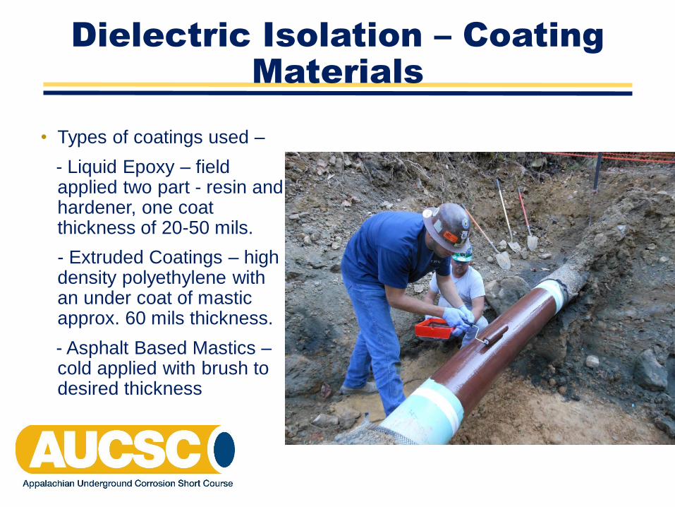
• Types of coatings used –
- Liquid Epoxy – field applied two part - resin and hardener, one coat thickness of 20-50 mils.
- Extruded Coatings – high density polyethylene with an under coat of mastic approx. 60 mils thickness.
- Asphalt Based Mastics –cold applied with brush to desired thickness

Dielectric Isolation – Coating Materials (Cont.)
- Fusion Bonded Epoxy – thin film coating, preheated to 400 to 500 F, with applied resin 10 to 18 mils depending on customer’s design requirements
- Cold Applied Tapes – plastic film with butyl rubber backing 15 to 35 mils.
- Cold Applied Waxes – grease type materials, blend of petroleum wax 20 to 30 mils.

Dielectric Isolation – Coating Materials (Cont.)

Dielectric Isolation Devices
• Meter Isolation & Above Ground Installations
Meter Swivels
- Installed at meter, isolates customer from pipeline
- Should be installed on outlet of meter

Dielectric Isolation Devices
• Meter Isolation & Above Ground Installations
(Cont’d)
Insulated Unions
- Used on above ground metering & regulation stations to isolate piping
- Usually installed on threaded pipe
- Not recommended for below ground installation

Dielectric Isolation Devices
• Plastic Pipe
- More economical to use versus weld-end fittings or flanges
- Recommended installing a minimum of 5 ft. of plastic pipe when insolating from steel pipe
- Very high dielectric properties
- No chance of failure due to shorting

• Weld-in Isolator
- Can only be installed by qualified welder (usually require NDE – x-ray and hydro test)
- Internal isolator components must be protected during welding process
Dielectric Isolation Devices

Dielectric Isolation Devises
• Insulated Flange Kit
- Components are non-conductive and provide isolation of pipes and fittings connected by flanges
- Flange kits consist of:
Nonconductive gasket
Isolation sleeves
Nonconductive washers

Dielectric Isolation Devices
• Isolation Compression Couplings
- For low to medium pressure pipelines
- For pipe up to 2” in diameter
- Non-conductive interior components
- Some devices prone to leakage
- Can fail due to soil stress or movement
- Less expensive than other alternatives

Isolation Compression Coupling

Dielectric Isolation Devises
• Isolation Bolted Couplings
- For pipelines 2” & larger in diameter
- Non-conductive interior components
- Can fail due to soil stress or movement
- Less expensive than other alternatives

Isolation Bolted Coupler

Testing Isolators
• Before installation check all isolators for electrical leakage. The resistance should be OL (over limit) on the meter.
• Test all isolators after installation before backfilling do not use a ohm meter after the isolator has been installed.
• Take pipe/soil potential reading on both sides of the isolator keeping the half cell in the same place. If the two readings are not different then the isolator may be shorted.

Gas Electronics
Model 601
Insulation Checker

Dielectric Isolation Precautions
• If the isolator is installed near high voltage AC lines or is in close proximity to electrical towers, precautions should be taken to prevent risks to personnel and damage from lightning strikes and stray AC currents.
- Methods commonly used:
Zinc ribbon
Magnesium anodes
*To provide a low resistant grounding system

Dielectric Isolation Precautions
• DOT subpart I, 192.467:
An insulating device may not be installed in an area where a combustible atmosphere is anticipated unless precautions are taken to prevent arcing.
- Methods commonly used:
Solid state device
Zinc grounding cell

Cased Pipeline Crossing

Cased Pipeline Crossings

Cased Pipeline Crossings
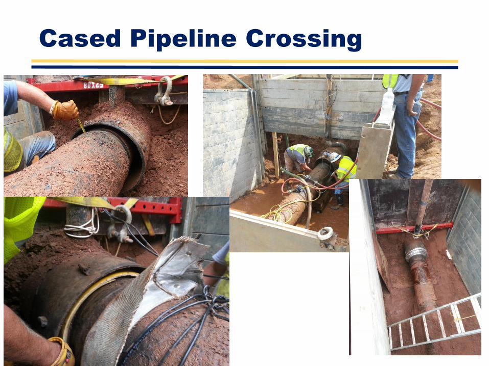
Cased Pipeline Crossing

Cased Pipeline Crossings

Cased Pipeline Crossing

Dielectric Isolation Protection
• DOT Subpart I, 192.455:– All isolated metallic fittings shall be coated and
cathodically protected.
• Improper installation and application practices are the primary reasons for failure of isolators!

Questions???
Thank You
Heather Groll