electrical engineering / electronics digital technology · electrical engineering / electronics...
TRANSCRIPT

Aus- und Weiterbildung GmbH ELABOTrainingsSystemeELABOTrainingsSysteme
®
elabo-ts.com
Electrical Engineering / Electronics Digital Technology
MadeinGermany

E L E C T R I C A L E N G I N E E R I N G / E L E C T R O N I C S / D I G I T A L
P R I N C I P L E S O F E L E C T R I C A L E N G I N E E R I N G
Analysis of electrical-engineering systems on component level
E L E C T R I C A L E N G I N E E R I N G / E L E C T R O N I C S / D I G I T A L

T E C H N O L O G Y
OVERVIEW HARDWARE Page 4
FUNCTION UND CONTROL ELEMENTS Page 6
ELECTRICAL ENGINEERING / ELECTRONICS Page 8
COMPONENTS / PLUG-IN COMPONENTS Page 9
COURSEWARE Page 12
ACCESSORIES Page 13
ELECTRICAL ENGINEERING Page 14
COMPONENTS Page 15
COURSEWARE Page 16
UNIVERSAL SOLUTIONS Page 18
LOGIC TRAINER / DIGITAL TECHNOLOGY Page 22
COURSEWARE Page 23
μ-TRAINER / DIGITAL TECHNOLOGY Page 24
COURSEWARE Page 25
MODULES Page 26
MOBILE SYSTEMS Page 30
MEASURING INSTRUMENTS Seite 32
INFORMATION AND CONSULTATION Seite 34
P
P
P
P
P
P
P
P
P
P
P
P
ELABOTrainingsSystemeELABOTrainingsSysteme
®T E C H N O L O G Y

E L E C T R I C A L E N G I N E E R I N G / E L E C T R O N I C S / D I G I T A L
4
H A R D W A R E
Measuring Instruments
Universal Supply Board
Electrical Networks Board II
Electronic Circuits Board II
Assembly Board Electronics
Assembly Board Safety
Device SetOptoelectronics
Device SetElectrical Engineering
Device SetElectronics
Electrical Engineering / Electronics
Color digital oscilloscope 60 MHz Digital multimeter Leakage Clamp MeterAnalog multimeter

T E C H N O L O G Y
5
ELABOTrainingsSystemeELABOTrainingsSysteme
®
Digital Technology
Digital Trainer Board
IC-Trainer
Universal Logic Module
8 Bit ADC Module
8 Bit DAC Module
Breadboard Wiring Set
Basic Set Logic ICs
Prototype Module

E L E C T R I C A L E N G I N E E R I N G / E L E C T R O N I C S / D I G I T A L
6
AT T R A C T I V E , P O W E R F U L A N D S A F E
Functions and operating elements
T H R E E - P H A S E C U R R E N T G E N E R ATO R
frequency: 1...120 Hz, adjustable in 1Hz steps
phase voltage: 0...10 V rms
line voltage: 0...17,3 V rms
line current: max. 400 mA rms all parameters available in the LC display
short-circuit-proof, reverse protection up to 40 V DC / 24 V AC
T R A N S F O R M E R
AC voltage sources 2 x 12 V AC / 0.2 A; 50 Hz (mains frequency), protected by polyswitchlyswitch
T E C H N O L O G Y
7
ELABOTrainingsSystemeELABOTrainingsSysteme
®
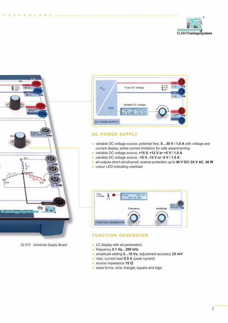
32 015 Universal Supply Board
F U N C T I O N G E N E R ATO R
LC display with all parameters frequency 0.1 Hz…200 kHz
amplitude setting 0…10 Vs, adjustment accuracy 10 mV max. current load 0.5 A (peak current) source impedance 1 wave forms: sine, triangle, square and logic
D C P O W E R S U P P LY
variable DC voltage source, potential free, 0…30 V / 1.0 A with voltage and current display, active current limitation for safe experimenting
variable DC voltage source, +15 V, +12 V or +5 V / 1.0 A
variable DC voltage source, -15 V, -12 V or -5 V / 1.0 A
all outputs short-circuit-proof, reverse protection up to 40 V DC/ 24 V AC, 40 W colour LED indicating overload

E L E C T R I C A L E N G I N E E R I N G / E L E C T R O N I C S / D I G I T A L
8
E L E C T R I C A L E N G I N E E R I N G / E L E C T R O N I C S
L E A R N I N G O B J E C T I V E S
Basics of electrical engineering
How to use oscilloscope, multimeter and
function generator
DC, AC and three-phase current technology
Operational amplifier
Technical Data
Voltage sources: DC +/-15 V or +/-12 V or +/- 5 V/1 A; DC 0...30 V/ max. 1 A with voltage and current display; AC 2 x 12 V/0,2 A (protected by polyswitch)
Function generator: frequency 0,1 Hz...200 kHz, variable amplitude (0…10 Vp) and wave form, display of all parameters
Three-phase current 0…10 Vrms; line voltage: 0…17.3 Vrmss; frequency: 1…120 Hz, adjustable, display of all parameters, phase current load: max. 400 mArms
Experimenting field: 4mm safety jacks arranged in a 19mm grid, surrounded by and electrically connected to four 2mm jacks.
Mains connection: 115 V / 230 V AC; 50 / 60 Hz; 75 W; protection class I
Safety: Supply outputs short-circuit-proof, reverse protection up to 40 V DC/ 24 V AC, 40 W
Electronic Circuits Board II
32 200 Electronic Circuits Board II
Voltage-, temperature- and light-dependent resistors
Behaviour of semiconductors: diodes, transistors,
thyristors
Electronic circuits, amplifiers, trigger and power
supply circuits
generator:

T E C H N O L O G Y
9
ELABOTrainingsSystemeELABOTrainingsSysteme
®
32 203 Device Set Electronics
Set of accessories, plugged on imprinted Storage Board:
Device Set Electronics
32 203 Device Set Electronics
28 film resistors 10 Ω...1 MΩ 1 VDR resistor 1 LDR resistor 1 PTC resistor 1 NTC resistor 11 capacitors 100 pF...1 μF 4 electrolytic capacitors 10 μF...470 μF 1 potentiometer linear 1 kΩ, 0,5 W 1 potentiometer linear 10 kΩ, 0,5 W 1 transformer coil N = 300 2 transformer coils N = 900 1 tape-wound core (1 pair) 1 coil 100 mH 1 transistor NPN, BC 237, base left 1 transistor NPN, BC 140, base left 1 transistor NPN, BC 140, base right 1 transistor PNP, BC 160, base left 1 unijunction transistor PN, 2N 4870 1 D-MOS field effect transistor, P-channel, BS 250 1 junction field effect transistor, N-channel, 2N 5485 1 junction field effect transistor, P-channel, 2N 5461 1 diac, ER 900 1 thyristor, TIC 106
1 triac, TIC 206 1 toggle switch 1 lamp, 15 V 1 light source 1 operational amplifier 1 GA-AS light emitting diode, red 1 Ge diode, AA118 6 Si diodes, 1N4007 1 Zener diode, ZPD 3.3 V 1 Zener diode ZPD 10 V 1 relay DC 12...15 V NOC 1 relay DC 12...15 V NCC
... to put things straight
The storage boards for the plug-in components are imprinted with the corresponding symbols.

E L E C T R I C A L E N G I N E E R I N G / E L E C T R O N I C S / D I G I T A L
1010
P L U G - I N C O M P O N E N T S
Passive and active components
Resistors series E12, 1 Ω ... 10 MΩ/2 W (1,0 1,2 1,5 1,8 2,2 2,7 3,3 3,9 4,7 5,6 6,8 8,2)
Potentiometers linear, 470 Ω, 1 kΩ, 4,7 kΩ, 10 kΩ, 47 kΩ, 0,5 W
Non-linear resistors VDR, LDR, NTC, PTC resistors
Capacitors series E6, 10 pF ... 1 μF (1,0 1,5 2,2 3,3 4,7 6,8)
Electrolytic capacitors values: 10 μF, 100 μF, 470 μF
Coils 100 mH transformer coils with 300 / 900 windings
Semiconductor components germanium and silicon diodes NPN and PNP transistors PN unijunction transistor D-MOS field effect transistor junction field effect transistor, N- and P-channel diac, thyristor, triac, IGBT operational amplifier Zener diode ZPD
values: 3,3 V, 10 V photo diode, photo transistor LEDs in red, green, yellow, blue, white
Switching and display switch, pushbutton, relayscomponents lamp
Other empty housings, with two and four pins
Optoelectronics Device Set Optoelectronics 32 104 (to complement device set 32 203)
photo transistor, photo diode optical coupler, solar cell LEDs

T E C H N O L O G Y
11
ELABOTrainingsSystemeELABOTrainingsSysteme
®
Component Overview
32 302 set of empty housings with 2 lamella plugs (10 pcs.)
32 305 set of empty housings with 2 lamella plugs (10 pcs.)
32 310 film resistor 10 Ω/2 W
32 311 film resistor 22 Ω/2 W
32 312 film resistor 33 Ω/2 W
32 313 film resistor 100 Ω/2 W
32 314 film resistor 220 Ω/2 W
32 315 film resistor 330 Ω/2 W
32 316 film resistor 470 Ω/2 W
32 317 film resistor 680 Ω/2 W
32 318 film resistor 1 kΩ/2 W
32 319 film resistor 2,2 kΩ/2 W
32 320 film resistor 4,7 kΩ/2 W
32 321 film resistor 10 kΩ/2 W
32 322 film resistor 22 kΩ/2 W
32 323 film resistor 47 kΩ/2 W
32 324 film resistor 100 kΩ/2 W
32 325 film resistor 1 MΩ/2 W
32 340 VDR resistor, 11 V/1 mA
32 342 NTC resistor (6 kΩ)
32 345 LDR resistor
32 370 capacitor 100 pF/500 V
32 371 capacitor 10 nF/500 V
32 372 capacitor 47 nF/500 V
32 373 capacitor 0,1 μF/160V
32 374 capacitor 0,22 μF/160 V
32 375 capacitor 0,47 μF/160 V
32 376 capacitor 1 μF/100 V
32 390 electrolytic capacitor 10 μF/63 V
32 391 electrolytic capacitor 100 μF/35 V
32 392 electrolytic capacitor 470 μF/35 V
32 402 linear potentiometer 1 kΩ 0,5 W
32 403 linear potentiometer 10 kΩ 0,5 W
32 420 transformer coil N = 300
32 421 transformer coil N = 900
32 422 coil 100 mH
32 430 tape-wourn core (1 pair)
32 440 Zener diode 10 V/40 mA
32 441 Zener diode 3,3 V/130 mA
32 442 GA-AS light emitting diode, red,
without dropping reststor
32 443 light source
32 444 LED, 5 mm, blue
32 445 Ge diode, AA118
32 446 LED, 5 mm, warm white 32 601 IC Socket 14 Pin
32 447 LED, 5 mm, yellow
32 448 LED, 5 mm, green
32 450 Si-Diode 1 A
32 480 toggle switch
32 490 lamp, green, 15 V
32 501 transistor NPN, BC237, base left
32 502 transistor NPN, BC140, base left
32 503 transistor NPN, BC140, base right
32 504 transistor PNP, BC160, base left
32 505 unijunction transistor, PN 2N4870
32 506 D-MOS field effect transistor, BS250, p-channel, gate left
32 507 JFET transistor 2N5485,
25 V/10 mA, n-channel, gate left
32 508 JFET transistor 2N5461,
20 V/10 mA, p-channel, gate left
32 510 diac, ER 900
32 511 thyristor, TIC 106
32 512 triac, TIC 206
32 520 photodiode
32 521 solar cell
32 522 optical coupler SFH615A
32 523 phototransistor LPT80A
32 598 operational amplifier OP741
with 4mm connection sockets on the top
32 485 relay DC 12...15 V NOC, 2A
32 486 relay DC 12...15 V NCC, 2A
32 601 IC socket, 14-pin, on plug-in plate for 19mm grid,
plate equipped with 2mm jacks for easy connec-
tion

E L E C T R I C A L E N G I N E E R I N G / E L E C T R O N I C S / D I G I T A L
Power Supply, External / InternalThe Electronic Circuits Board II is operational when the mains voltage is applied.The presence of the mains voltage is indicated by a yellow indicator lamp in the mains switch.The readiness indication of the individual DC and AC voltage sources is provided by a glowing green LED at the relevant outputs. The glowing green LED in the supply block displays the existing internal DC voltage for operating the processor. If this LED does not glow, it means that owing to an overload or a faulty circuit (feedback), the voltage supply gets switched off. Switch off the device and examine your experimental circuit.Correct the faulty circuit and switch on the device again.If the central LED and the displays remain dark, pleas refer to the user guide.
Fixed DC VoltageThe xed voltage source supplies, with respect to the device ground, and depending on the setting, at output „+DC“, +15 V, +12 V or +5 V and at output „-DC“, -15 V, -12 V or -5 V. Each of the two outputs can be loaded with at least up to 1 A. The glowing green LED indicates proper operation of the relevant output of the xed voltage source. If there is an overload short-circuit, the LED glows red. If you enter the overload range above 1 A, the LED rst starts to alternately ash red and green. The earth of these outputs is the central earth of the device.
The setting of the xed voltage is done using the incremental ad uster and the display of the variable DC. To get to the setting mode for the xed operating voltages, the incremental adjuster of the variable voltage must be kept pressed for at least 1s. Thereupon, the LC display changes into setting mode and indicates as such.
By rotating the incremental adjuster of the variable voltage to the right and the left, you can select the xed voltage and con rm it by brie y pressing the incremental adjuster of the va-riable voltage. This sets the selected xed voltage, the yellow LED with the corresponding voltage value glows and the LC display of the variable voltage once again shows the data related to the variable voltage source.
Variable DC VoltageThe adjustable DC source serves for providing a potential-free DC between 0 V and 30 V. The setting of the output voltage is done by means of the incremental adjuster. The current voltage at the output of the adjustable DC source is displayed at the LC display in the unloaded state with an absolute accuracy of ±20 mV. The output is nominally loadable up to minimum 1 A. From 1 A load current onwards, you enter the overload domain. The voltage continues to be applied. At the output, the overcurrent domain is indicated by green red ashing of the LED.A load current from 1.2 A onwards is overload. The LED changes to red and the display shows overload. The output voltage is chan-ged down. For information, the load current is displayed with an accuracy of at least 5 %.
The DC voltage setting is done with the incremental adjuster and can be set between 0 and 30 V. The electrical isolation with respect to the earth of the device facilitates the setting between 0 and +30 V or 0 and -30 V. In addition, the variable DC can be connected in series with the xed DC voltages, which allows additional combinations.This adjuster can be rotated onward continuously without any stop. If rota-ted slowly to the right, the signal amplitude is incremented in small steps (10mV). If rotated slowly to the left, the signal amplitude is decremented in
small steps (mV). Rotating fast results in a change in the signal amplitude in large steps up to 1 V.ressing brie y on the adjustment knob resets the DC voltage back to 0 V. The glowing green LED indicates proper operation of the
relevant output of the variable DC voltage.
If there is an overload / short-circuit, the LED glows red.In case of overload from 1.2 A onwards, feedback or short-circuit „Over-load“ is shown in the display.
TransformerThe AC voltage source „Transformer“ provides two separate AC voltages, potential-isolated from the device.The nominal voltages are speci ed as 12 VRMS with a nominal load of 200 mA.Both the sources are the isolated secondary windings of a transformer. The no-load voltage is higher, load-dependent on the nominal value. The output voltages are present at the 4mm safety sockets.
Both outputs are protected against overload with polyswitch fuses.A glowing green LED indicates proper operation of the relevant output of the transformer. If the LED goes off, the output is overloaded.
FunctiongeneratorThe function generator has a signal output. The signal voltage is present at the 4mm safety socket „OUTPUT“ opposite the central device earth.The signal amplitude setting is done with the incremental adjuster „Amplitu-de“ and can be set between 0 and 10 VS.This adjuster can be rotated onward continuously without any stop. If rota-ted slowly to the right, the signal amplitude is incremented in small steps (10 mV). If rotated slowly to the left, the signal amplitude is decremented in small steps (mV). Rotating fast results in a change in the signal amplitude in large steps up to 1 V.Pressing brie y on the adjustment knob resets the amplitude to 0 V (Off).The output amplitude is shown in the LC display.
The curve form (sinus, triangle, rectangle, logic) is selected with the „Waveform“ button. Upon pressing the button once, the next curve form in the sequence is selected, in the order:
Sine Triangle S uare ogic Sineat the signal output. The curve form is shown in the LC display.
The signal frequency is depicted on the LC display.The setting of the frequency is done by means of the incremental adjuster „Frequency“. This adjuster can be rotated onward conti-nuously without any stop. If rotated slowly to the right, the frequency is incremented in small steps (0.01 to the earth range). If rotated slowly to the left, the frequency is decremented in small steps. Fast turning effects a frequency change in large steps to the left of the decimal.Fast selection of the frequency range (100 Hz, 1 kHz, 10 kHz and 100 kHz) is possible by pressing on the setting knob.
Three-phase sourceThe electronic 3-phase current source generates, at the three outputs L1, L2 and L3, a sinusoidal AC with a phase difference of ±120° between the neighbouring outputs. The rotary eld is right-rotating. The effective voltage at the phases is adjustable up to a maximum of 10 VRMS with respect to the star node.The phase voltages are present at a 4mm safety socket.The phase voltage is shown in the LC display.The star node of the three-phase source is connected to the central earth of the device. The signal amplitude
setting is done with the incremental adjuster „Amplitude“ and can be set between 0 and 10 VRMS.This adjuster can be rotated onward continuously without any stop. If rotated slowly to the right, the phase voltage (signal amplitude) is incremented in small steps (10 mV). If rotated slowly to the left, the signal amplitude is decremented in small steps (mV). Rotating fast results in a change in the signal amplitude in large steps up to 1 VRMS.Pressing brie y on the adjustment knob switches off the outputs (0 V). „OFF“ appears in the display however, the last phase voltage that has been set remains. Pressing on it again switches on the outputs again.The signal frequency is shown in the LC display. The setting of the frequency from 1 Hz to 120 Hz takes place via the incremental encoder „Frequency“. This adjuster can be rotated onward continuously without any stop. When rotated to the right, the frequency is incremented in 1 Hz steps. When rotated to the left, the frequency is decremented in 1 Hz steps.Fast resetting to 50 Hz (60 Hz) can be achieved by pressing on the adjustment knob. The starting and resetting frequencies are set in the service menu.
12
C O U R S E W A R E
Printed and on CD!
TECHNOCard®
t results iment knob
DC voltag
geves for pr
adjuster. Tsolute accble up to me output, tards is ove load cur
ternal The ElecThe presThe readLED at tThe glowprocessthe voltaCorrect If the ce
32201-ENG
TECHNOCard ®Electronic Circuits Board II
Please observe all the applicable safety re-gulations, laboratory rules and take the ne-cessary safety precautions when setting up and testing the systems!
CAUTION!
4.1
Aus- und Weiterbildung GmbH ELABOTrainingsSystemeELABOTrainingsSysteme
®
Im Hüttental 11 85125 Kinding - GermanyTel.: + 49 (0) 84 67 / 84 04 - 0 Fax: + 49 (0) 84 67 / 84 04 44E-mail: [email protected]
Mains On/Off switch
Mains voltage input, 230 V AC 50 … 60 Hz
AC outputs of the transfor-mer 2 X 12 V AC at INOM = 0.2 A; 50 Hz/60 Hz (secure via PolySwitch)
Incremental switch for phase voltage and frequency of the three-phase generator
Function generatorwith LC-display
Incremental switch for amplitude and frequency of the function generator
Selector button for wave shape of the function generator
Three-phase generator with LC-display; star-voltage UPh = 0…10 VRMS, maximum line current 400 mARMS, frequency adjustable 1 … 120 Hz
4 mm sockets with 19 mm spacing, surrounded with 4, 2 mm sockets, electrically connected and arranged in a star-shape
Experiment (exercise) areas
Adjustable DC voltage source, potential free, short-circuit protected, DC output 0...30 V / IMAX = 1.0 A with digital voltage and current display
Incremental switch of the adjustable DC voltage 0 … 30 V DC, upon pressing the adjuster brie y, the voltage is reset to 0 V.Press the adjuster and hold it down for about 1 s, where upon the adjustment menu for the xed voltage outputs DC is opened.
LED-display of the xed voltage outputs:±15 V, ±12 V or ±5 V
DC voltage source, short-circuit protected, -15 V, -12 V or -5 V / IMAX = 1.0 A
DC voltage source, short-circuit protected, +15 V, +12 V or +5 V / IMAX = 1.0 A
32201-ENG TECHNOCard® Electronic Circuits Board II
Direct Current Technology
32120CD-ENG Instructor‘s manual32121CD-ENG Student manual
Alternating Current Technology
32122CD-ENG Instructor‘s manual32123CD-ENG Student manual
Semiconductor Devices in Electronics
32124CD-ENG Instructor‘s manual32125CD-ENG Student manual
Electronic Circuits
32126CD-ENG Instructor‘s manual32127CD-ENG Student manual
Direct Current Technology
Electric circuit Ohm's law Electrical resistance Voltage and current error
circuits Equivalent voltage
sources Interconnection of voltage
sources Electrical energy and
power Efficiency and electrical
power Power, voltage and current
matching
Alternating Current Technology
Types of current (voltage) and their characteristics
Active power of alternating voltages
Three-phase AC Capacitor in an AC circuit Coil in an AC circuit Combination of reactive
and active resistance Oscillating circuit RLC filter circuit Transformers
Semiconductor Devices in Electronics
Rectifier diodes Rectifier circuits Zener diodes Voltage stabilization Overvoltage protection Voltage limitation Light-emitting diodes Bipolar transistors Basic amplifier circuits Unipolar transistors Junction FET MOS FET Unijunction transistor (UJT) Diac Thyristor Triac Phase control
Electronic Circuits
Multi-stage amplifiers Darlington amplifier Emitter-coupled amplifiers Phase inverters Differential amplifiers DC amplifiers Push-pull amplifiers Feedback Inverting op-amps Non-inverting op-amps Impedance converters Summing op-amp Subtracting op-amp Integrating op-amp Differentiating op-amp Sinewave generators Squarewave generators
M A N UA L C O N T E N T S
Aus- und Weiterbildung GmbH ELABOTrainingsSystemeELABOTrainingsSysteme
®ELABO Im Hüttental 11 85125 Kinding - GermanyTel.: +49 (0) 84 67/ 84 04 - 0 Fax: +49 (0) 84 67/ 84 04 44E-mail: [email protected]
ManualsDirect Current Technology
Instructor's Manual
Version 4.4 – Order No. 32120CD-ENG
Practical Experiments, with Solutions
Direct Current Technology
ELABOTrainingsSystemeELABOTrainingsSysteme
®
Alternating Current Technology
Practical Experiments, with Solutions
Alternating Current Technology
Instructor's Manual
Version 4.4 – Order No. 32122CD-ENG
ELABOTrainingsSystemeELABOTrainingsSysteme
®
o
Semiconductor Devices
in Electronics
Practical Experiments, with Solutions
Semiconductor Devices in Electronics
ELABOTrainingsSystemeELABOTrainingsSysteme
®
Instructor's Manual
Version 4.4 – Order No. 32124CD-ENG
Electronic Circuits
Instructor's Manual
Version 4.4 – Order No. 32126CD-ENG
Practical Experiments, with Solutions
Electronic Circuits
ELABOTrainingsSystemeELABOTrainingsSysteme
®

T E C H N O L O G Y
13
ELABOTrainingsSystemeELABOTrainingsSysteme
®
A C C E S S O R I E S
Making connections …
Components and connections are provided with gold-plated lamella plugs assuring resistance against corrosion and low contact resistance.
2 mm connections
70 connecting plugs 2 mm (C6000306) Set of connecting leads 2 mm, 28 parts (90 049)
On the experimenting field provided with 4/2mm sockets, connections between components and to the power supply bar are made with 2mm connectors.
90 021 Set of 4 mm connections − classic
20 connecting plugs 4 mm 8 connecting leads with 4mm plugs
On the experimenting field provided with 4mm sockets, electrical connections are made with 4mm connectors or 4mm safety connectors.
4 mm connections – safety
Set of safety connecting leads, 11 parts (90 030) Set of safety bridging plugs, 24 parts, multi-color (90 031)
Measurement accessories
Adapter, BNC plug to 4mm safety socket (C6010235)
Three adapters BNC to 4mm safety connectors are required for connecting standard oscilloscopes.
against corrosion

E L E C T R I C A L E N G I N E E R I N G / E L E C T R O N I C S / D I G I T A L
14
E L E C T R I C A L E N G I N E E R I N G
Electrical Networks Board II
32 020 Electrical Networks Board II
L E A R N I N G O B J E C T I V E S
Basics of electrical engineering
How to use oscilloscope,
multimeter and function generator
Passive components in the DC circuit
Capacitors and coils in the AC circuit
Transformers
Three-phase current systems
Behaviour of semiconductors:
diodes, transistors, thyristors
Operational amplifiers
Technical Data
Voltage sources: DC +/-15 V or +/-12 V or +/- 5 V/1 A; DC 0...30 V / max. 1 A with voltage and current display; AC 2 x 12 V/0,2 A (protected by polyswitch)
Function generator: Frequency 0,1 Hz...200 kHz, variable amplitude (0…10Vp) and wave form, display of all parameters
Three-phase current Phase voltage: 0…10 Vrms; line voltage: 0…17.3 Vrms; frequency: 1…120 Hz, adjustable, display of all parameters, phase current load: max. 400 mArms
Experimenting field: 42 plug-in areas in a 19mm grid, each with 4 electrically connected 4mm safety jacks.
Mains connection: 115 V / 230 V AC; 50 / 60 Hz; 75 W; protection class I
Safety: Supply outputs short-circuit-proof, reverse protection up to 40 V DC / 24 V AC, 40 W
generator:

T E C H N O L O G Y
15
ELABOTrainingsSystemeELABOTrainingsSysteme
®
Device Set Basics
32 002 Device Set Basics
16 film resistors 10 Ω...10 kΩ 1 LDR resistor 1 NTC resistor 3 capacitors 0,22 μF...1 μF 1 potentiometer linear 1 kΩ 1 transformer coil N = 300 2 transformer coils N = 900 1 tape-wound core (1 pair) 1 coil 100 mH 1 GA-AS light emitting diode, red
1 Si diode 1N4007 1 Zener diode ZPD 10 V 1 transistor NPN BC 237, base left 1 thyristor TIC 106 1 toggle switch 1 lamp 15 V 1 light source 1 operational amplifier 1 relay 12...15 V DC, NOC 1 relay 12...15 V DC, NCC
Technical Data
Set of accessories, plugged on imprinted Storage Board:
…with storage facilities for insulated and non-insulated bridging plugs

E L E C T R I C A L E N G I N E E R I N G / E L E C T R O N I C S / D I G I T A L
16
C O U R S E W A R E
Manual Content
The electrical circuit Ohm’s Law Electrical resistors Interconnection of voltage sources Electrical power and work Efficiency Types of current and their parameters Effective power of AC voltages Three-phase AC current The capacitor in the AC circuit The coil in an AC circuit Interconnection of reactive and active resistors Oscillating circuits RLC filter circuit (filter) Transformers Diodes and rectifier circuits Bipolar transistors The triode thyristor Operational amplifier Square wave generatorsPrinted and on CD!
32003CD-ENG Instructor’s Manual, incl. CDDescription of theory and guided practical experiments,
with solutions, color print
32004CD-ENG Student Manual, incl. CDUnrestricted copying license for educational institutions,
Guided practical experiments, greyscale print
Fundamentals
of Electrical Engineering
Instructor's Manual
Version 4.4 – Order No. 32003CD-ENG
Fundamentals of Electrical Engineering
Practical Experiments, with Solutions ELABOTrainingsSystemeELABOTrainingsSysteme
®
Fundamentals
of Electrical Engineering
Student Manual
Version 4.4 – Order No. 32004CD-ENG
Fundamentals of Electrical Engineering
Practical Experiments
Aus- und Weiterbildung GmbH ELABOTrainingsSystemeELABOTrainingsSysteme
®ELABO Im Hüttental 11 85125 Kinding - GermanyTel.: +49 (0) 84 67/ 84 04 - 0 Fax: +49 (0) 84 67/ 84 04 44E-mail: [email protected]

T E C H N O L O G Y
17
ELABOTrainingsSystemeELABOTrainingsSysteme
®
Power Supply, External / InternalThe Electronic Networks Board II is operational when the mains voltage is applied.The presence of the mains voltage is indicated by a yellow indicator lamp in the mains switch.The readiness indication of the individual DC and AC voltage sources is provided by a glowing green LED at the relevant outputs. The glowing green LED in the supply block displays the existing internal DC voltage for operating the processor. If this LED does not glow, it means that owing to an overload or a faulty circuit (feedback), the voltage supply gets switched off. Switch off the device and examine your experimental circuit.Correct the faulty circuit and switch on the device again.If the central LED and the displays remain dark, pleas refer to the user guide.
Fixed DC VoltageThe xed voltage source supplies, with respect to the device ground, and depending on the setting, at output „+DC“, +15 V, +12 V or +5 V and at output „-DC“, -15 V, -12 V or -5 V. Each of the two outputs can be loaded with at least up to 1 A. The glowing green LED indicates proper operation of the relevant output of the xed voltage source. If there is an overload / short-circuit, the LED glows red. If you enter the overload range above 1 A, the LED rst starts to alternately ash red and green. The earth of these outputs is the central earth of the device.
The setting of the xed voltage is done using the incremental adjuster and the display of the variable DC. To get to the setting mode for the xed operating voltages, the incremental adjuster of the variable voltage must be kept pressed for at least 1s. Thereupon, the LC display changes into setting mode and indicates as such.
By rotating the incremental adjuster of the variable voltage to the right and the left, you can select the xed voltage and con rm it by brie y pressing the incremental adjuster of the va-riable voltage. This sets the selected xed voltage, the yellow LED with the corresponding voltage value glows and the LC display of the variable voltage once again shows the data related to the variable voltage source.
Variable DC VoltageThe adjustable DC source serves for providing a potential-free DC between 0 V and 30 V. The setting of the output voltage is done by means of the incremental adjuster. The current voltage at the output of the adjustable DC source is displayed at the LC display in the unloaded state with an absolute accuracy of ±20 mV. The output is nominally loadable up to minimum 1 A. From 1 A load current onwards, you enter the overload domain. The voltage continues to be applied. At the output, the overcurrent domain is indicated by green/red ashing of the LED.A load current from 1.2 A onwards is overload. The LED changes to red and the display shows overload. The output voltage is chan-ged down. For information, the load current is displayed with an accuracy of at least 5 %.
The DC voltage setting is done with the incremental adjuster and can be set between 0 and 30 V. The electrical isolation with respect to the earth of the device facilitates the setting between 0 and +30 V or 0 and -30 V. In addition, the variable DC can be connected in series with the xed DC voltages, which allows additional combinations.This adjuster can be rotated onward continuously without any stop. If rota-ted slowly to the right, the signal amplitude is incremented in small steps (10mV). If rotated slowly to the left, the signal amplitude is decremented in
small steps (mV). Rotating fast results in a change in the signal amplitude in large steps up to 1 V.Pressing brie y on the adjustment knob resets the DC voltage back to 0 V. The glowing green LED indicates proper operation of the relevant output of the variable DC voltage.
If there is an overload / short-circuit, the LED glows red.In case of overload from 1.2 A onwards, feedback or short-circuit „Over-load“ is shown in the display.
TransformerThe AC voltage source „Transformer“ provides two separate AC voltages, potential-isolated from the device.The nominal voltages are speci ed as 12 VRMS with a nominal load of 200 mA.Both the sources are the isolated secondary windings of a transformer. The no-load voltage is higher, load-dependent on the nominal value. The output voltages are present at the 4mm safety sockets.
Both outputs are protected against overload with polyswitch fuses.A glowing green LED indicates proper operation of the relevant output of the transformer. If the LED goes off, the output is overloaded.
Function generatorThe function generator has a signal output. The signal voltage is present at the 4mm safety socket „OUTPUT“ opposite the central device earth.The signal amplitude setting is done with the incremental adjuster „Amplitu-de“ and can be set between 0 and 10 VS.This adjuster can be rotated onward continuously without any stop. If rota-ted slowly to the right, the signal amplitude is incremented in small steps (10 mV). If rotated slowly to the left, the signal amplitude is decremented in small steps (mV). Rotating fast results in a change in the signal amplitude in large steps up to 1 V.Pressing brie y on the adjustment knob resets the amplitude to 0 V (Off).The output amplitude is shown in the LC display.
The curve form (sinus, triangle, rectangle, logic) is selected with the „Waveform“ button. Upon pressing the button once, the next curve form in the sequence is selected, in the order:
Sine Triangle S uare ogic Sineat the signal output. The curve form is shown in the LC display.
The signal frequency is depicted on the LC display.The setting of the frequency is done by means of the incremental adjuster „Frequency“. This adjuster can be rotated onward conti-nuously without any stop. If rotated slowly to the right, the frequency is incremented in small steps (0.01 to the earth range). If rotated slowly to the left, the frequency is decremented in small steps. Fast turning effects a frequency change in large steps to the left of the decimal.Fast selection of the frequency range (100 Hz, 1 kHz, 10 kHz and 100 kHz) is possible by pressing on the setting knob.
Three-phase sourceThe electronic 3-phase current source generates, at the three outputs L1, L2 and L3, a sinusoidal AC with a phase difference of ±120° between the neighbouring outputs. The rotary eld is right-rotating. The effective voltage at the phases is adjustable up to a maximum of 10 VRMS with respect to the star node.The phase voltages are present at a 4mm safety socket.The phase voltage is shown in the LC display.The star node of the three-phase source is connected to the central earth of the device. The signal amplitude
setting is done with the incremental adjuster „Amplitude“ and can be set between 0 and 10 VRMS.This adjuster can be rotated onward continuously without any stop. If rotated slowly to the right, the phase voltage (signal amplitude) is incremented in small steps (10 mV). If rotated slowly to the left, the signal amplitude is decremented in small steps (mV). Rotating fast results in a change in the signal amplitude in large steps up to 1 VRMS.Pressing brie y on the adjustment knob switches off the outputs (0 V). „OFF“ appears in the display; however, the last phase voltage that has been set remains. Pressing on it again switches on the outputs again.The signal frequency is shown in the LC display. The setting of the frequency from 1 Hz to 120 Hz takes place via the incremental encoder „Frequency“. This adjuster can be rotated onward continuously without any stop. When rotated to the right, the frequency is incremented in 1 Hz steps. When rotated to the left, the frequency is decremented in 1 Hz steps.Fast resetting to 50 Hz (60 Hz) can be achieved by pressing on the adjustment knob. The starting and resetting frequencies are set in the service menu.
32021-ENG TECHNOCard ® Electrical Networks Board II
TECHNOCards®
The TECHNOCards® are very useful complements to the training system. They are a kind of compact, clearly laid-out knowledge store for reference during practical experiments.
Display sheets in format 303 mm x 426 mm Double-sided color print Rigid, durable quality
I is opge is ndivid
pply low, ioff. Sch onys rem
xedendin
put „-D at leaglow
he xeD glowts to atral ea
voltat to th
e voltaetting
ental ae and s the d thevoltag
DC beoutp
oad cu indics to reaccur
DC voetweee deviditionges, wadjustowly V). If ampliack to
If there is aIn case of load“ is sh
32021-ENG4.1
TECHNOCard ®Electrical Networks Board II
Please observe all the applicable safety re-gulations, laboratory rules and take the ne-cessary safety precautions when setting up and testing the systems!
CAUTION!Aus- und Weiterbildung GmbH ELABOTrainingsSystemeELABOTrainingsSysteme
®
Im Hüttental 11 85125 Kinding - GermanyTel.: + 49 (0) 84 67 / 84 04 - 0 Fax: + 49 (0) 84 67 / 84 04 44E-mail: [email protected]
Mains On/Off switch
Mains voltage input, 230 V AC 50 … 60 Hz
AC outputs of the transfor-mer 2 X 12 V AC at INOM = 0.2 A; 50 Hz/60 Hz (secure via PolySwitch)
Function generatorwith LC-display
Incremental switch for amplitude and frequency of the function generator
Selector button for wave shape of the function generator
Three-phase generator with LC-display; star-voltage UPh = 0…10 VRMS, maximum line current 400 mARMS, frequency adjustable 1 … 120 Hz
6 x patch elds with 19 mm spacing, electrically connected and arranged 4 pieces of 4mm safety sockets
Experiment (exercise) areas
Adjustable DC voltage source, potential free, short-circuit protected, DC output 0...30 V / IMAX = 1.0 A with digital voltage and current display
Incremental switch of the adjustable DC voltage 0 … 30 V DC, upon pressing the adjuster brie y, the voltage is reset to 0 V.Press the adjuster and hold it down for about 1 s, where upon the adjustment menu for the xed voltage outputs DC is opened.
LED-display of the xed voltage outputs:±15 V, ±12 V or ±5 V
DC voltage source, short-circuit protected, -15 V, -12 V or -5 V / IMAX = 1.0 A
DC voltage source, short-circuit protected, +15 V, +12 V or +5 V / IMAX = 1.0 A
Incremental switch for phase voltage and frequency of the three-phase generator

E L E C T R I C A L E N G I N E E R I N G / E L E C T R O N I C S / D I G I T A L
18
U N I V E R S A L S O L U T I O N S
Universal Supply Board
32 015 Universal Supply Board
Technical Data
Voltage sources: DC +/-15 V or +/-12 V or +/- 5 V/1 A; DC 0...30 V / max. 1 A with voltage and current display; AC 2 x 12 V/0,2 A (protected by polyswitch)
Function generator: Frequency 0,1 Hz...200 kHz, variable amplitude (0…10 Vp) and wave form, display of all parameters
Three-phase current Phase voltage: 0…10 Vrms; line voltage: 0…17.3 Vrms; frequency: 1…120 Hz, adjustable, display of all parameters, phase current load: max. 400 mArms
Mains connection: 115 V / 230 V AC; 50 / 60 Hz; 75 W; protection class I
Safety: Supply outputs short-circuit-proof, reverse protection up to 40 V DC / 24 V AC, 40 W
generator:

T E C H N O L O G Y
Aus- und Weiterbildung GmbH ELABOTrainingsSystemeELABOTrainingsSysteme
®ELABO Im Hüttental 11 85125 Kinding - GermanyTel.: +49 (0) 84 67/ 84 04 - 0 Fax: +49 (0) 84 67/ 84 04 44E-mail: [email protected]
19
ELABOTrainingsSystemeELABOTrainingsSysteme
®
Assembly Boards
… are an ideal solution for workplaces that are provided with a power supply and a function generator or in conjunction with the Universal Supply Board 32 015.
+
+
+
E X T E R NA L P O W E R S U P P LY . . .
A S S E M B LY B OA R D S
D E V I C E S E T S
C O U R S E W A R E
AAuELABOELAABOELABOELABOTrTT
ELABOIm Hüttental 11 85125 Kinding - GermanyTel.: +49 (0) 84 67/ 84 04 - 0Fax: +49 (0) 84 67/ 84 04 44E-mail: [email protected]
32 012 Assembly Board Safety 32 202 Assembly Board Electronics

E L E C T R I C A L E N G I N E E R I N G / E L E C T R O N I C S / D I G I T A L
20
E L E C T R I C A L E N G I N E E R I N G / E L E C T R O N I C S / D I G I T A L

T E C H N O L O G Y
21
ELABOTrainingsSystemeELABOTrainingsSysteme
®T E C H N O L O G Y

E L E C T R I C A L E N G I N E E R I N G / E L E C T R O N I C S / D I G I T A L
22
D I G I TA L T E C H N O L O G Y
Digital Trainer Board
33 000 Digital Trainer Board
L E A R N I N G O B J E C T I V E S
Basic logical circuits, properties and parameters of digital circuits
The laws of Boolean algebra
Multivibrators and counter circuits
Register and memory
Codes and code converters
Arithmetic circuits
Configuring and analysing controls with digital components
Power supply: +5 V DC/5 A stabilized, short-circuit-proof
Clock generator: 0...10 kHz with subsequent frequency divider, division factors: 1:2/4/8/16
Mains connection: 110...240 V AC; 50...60 Hz
Features: Pushbuttons and switchesAND, NAND, OR, NOR, XOR gates, invertersMonoflop and flipflopsAdders, binary and decimal countersLED and 7-segment displaysVoltage-supplied plug-in fields for additional modules or IC sockets
Technical Data

T E C H N O L O G Y
33008-ENG
TECHNOCard®
Digital Trainer BoardPlease observe all necessary safe-ty regulations, laboratory rules and required protective measures for in-stalling and testing the equipment!
CAUTION!
power switch and power supply for integrated short-circuit-proof power pack
4.3
Aus- und Weiterbildung GmbH ELABOTrainingsSystemeELABOTrainingsSysteme
®
Im Hüttental 11 85125 Kinding - GermanyTel.: + 49 (0) 84 67 / 84 04 - 0 Fax: + 49 (0) 84 67 / 84 04 44E-mail: [email protected]
8 bounce-free L/H input switches (snap and tap)
toggle switch (not debounced)
pushbutton for free use (not debounced)
function tables for the logical gates used
continuously adjustable clock generator 0 - 10 kHz with subsequent divider (division factors 2, 4, 8 and 16)
mono op; time setting with potentiometer (max.10 s), control by positive or negative edge
inverters
jack row for supply of +5 V and GND
decimal counter with optical display
4-bit full adder
2-bit buffer memories (D- ip op) with release
8-bit decimal/hexideci-mal display (switchable) with release and reset
function tables for the ip ops used
4-bit forward/back-ward binary counter
OR/NOR gates with 2 and 4 inputs
JK master-slave ip opsXOR gates
3 x voltage supplyfor additional plug-in modules
AND/NAND gates with 2 and 4 inputs
pilot lamp for voltage +5 V DC
8 LEDs with preceding drivers: 6 x red, 1 x yellow, 1 x green
23
C O U R S E W A R EELABOTrainingsSystemeELABOTrainingsSysteme
®
Manual
Comparison of analog and digital technology Basic logic circuits Basic component combinations in digital techniques TTL integrated circuits in practice The laws of Boolean algebra Designing digital circuits Circuit analysis
Multivibrators, counter circuits Shift registers, memory registers Codes and code converters Calculation circuits Analog-digital – digital-analog converters Multiplexer ― demultiplexer Application examples
Content
TECHNOCard®
power switch and power supply for integrated short-circuit-proof power pack
OR/NOR gateswith 2 and 4 inputs
JXOR gates
3 x voltage supplyfor additional plug-
AND/NAND gates with 2 and 4 inputs
pilot lamp for voltage +5 V DC
33008-ENG
TECHNOCard®
Digital Trainer BoardPlease observe all necessary safe-ty regulations, laboratory rules and required protective measures for in-stalling and testing the equipment!
CAUTION!
power switch and power supply for integrated short-circuit-proof power pack
4.3
Aus- und Weiterbildung GmbH ELABOTrainingsSystemeELABOTrainingsSysteme
®
Im Hüttental 11 85125 Kinding - GermanyTel.: + 49 (0) 84 67 / 84 04 - 0 Fax: + 49 (0) 84 67 / 84 04 44E-mail: [email protected]
8 bounce-free L/H input switches (snap and tap)
toggle switch (not debounced)
pushbutton for free use (not debounced)
function tables for the logical gates used
continuously adjustable clock generator 0 - 10 kHz with subsequent divider (division factors 2, 4, 8 and 16)
mono op; time setting with potentiometer (max.10 s), control by positive or negative edge
inverters
jack row for supply of +5 V and GND
decimal counter with optical display
4-bit full adder
2-bit buffer memories (D- ip op) with release
8-bit decimal/hexideci-mal display (switchable) with release and reset
function tables for the ip ops used
4-bit forward/back-ward binary counter
OR/NOR gates with 2 and 4 inputs
JK master-slave ip opsXOR gates
3 x voltage supplyfor additional plug-in modules
AND/NAND gates with 2 and 4 inputs
pilot lamp for voltage +5 V DC
8 LEDs with preceding drivers: 6 x red, 1 x yellow, 1 x green
33008-ENG Digital Trainer Board
Fundamentals of
Digital Technology
Instructor's ManualVersion 4.2 – Order No. 33006CD-ENG
Practical Experiments, with Solutions
Fundamentals of Digital Technology
ELABOTrainingsSystemeELABOTrainingsSysteme
®
Fundamentals of
Digital Technology
Student ManualVersion 4.2 – Order No. 33007CD-ENG
Practical Experiments, with Solutions
Fundamentals of Digital Technology
ELABOTrainingsSystemeELABOTrainingsSysteme
®
Printed and on CD!
33006CD-ENG Fundamentals of Digital Technology
Instructor's Manual
33007CD-ENGFundamentals of Digital Technology
Student Manual
AAus- und Weiterbildung GmbH ELABOTrainingsSystemeELAABOELABOELABOTrainingsSystemeTrainingsSystemeTrainingsSysteme
®ELABOTrainingsSysteme GmbHIm Hüttental 11 85125 Kinding - GermanyTel.: +49 (0) 84 67/ 84 04 - 0 Fax: +49 (0) 84 67/ 84 04 44E-mail: [email protected]
TeachwareOrder No. 33006CD-ENG
Fundamentals of Digital TechnologyTrainer Section
Version 4.2

E L E C T R I C A L E N G I N E E R I N G / E L E C T R O N I C S / D I G I T A L
24
I C - T R A I N E R / D I G I TA L T E C H N O L O G Y
L E A R N I N G O B J E C T I V E S
μ-Trainer Application Board II
Analysis of open loop controlled systems with digital components
Synthesis of open loop controlled systems with digital components
Logic circuits in practice
Configuring circuits with ICs
Circuit characteristics
Instruments and procedures of measuring
Complex logic circuits and converters
μ pp
33 400 μ-Trainer Application Board II with 33 406 Universal Logic Module
Technical Data
Computer interface via Ethernet 2mm connectors or bus connectors (8-pin, 1:1, ribbon cable)
Power supply 110 … 240 V AC, 50 … 60Hz Internal operating voltages 3.3 V; 5.0 V; +/-12.0 V
Logic level 3.3 V or 5.0 V Central on/off switch Dimensions: 532 x 297 x 85 mm Desk housing device

T E C H N O L O G Y
25
ELABOTrainingsSystemeELABOTrainingsSysteme
®
C O U R S E W A R E
Manual
Content
Introduction to digital technology Basic logic circuits Logic circuits in practice Boolean switching algebra De Morgan's law Circuit synthesis Disjunctive normal form Conjunctive normal form The KV diagram Codes and code converters
Adder and subtracter Comparators Flipflops Monostable multivibrators Astable multivibrators Counter circuits Shiftregisters Multiplexer and demultiplexer Analog digital converter Digital analog converter
Printed and on CD!
Fundamentals of and Experiments
in Digital Technology
μ-Trainer Edition
Solution book for the trainer
Version 4.2 - Order No. 33101CD-ENG
Fundamentals of and Experiments in Digital Technology
ELABOTrainingsSystemeELABOTrainingsSysteme
®
Practical experiments for the student
Version 4.2 - Order No. 33100CD-ENG
Fundamentals of and Experiments in Digital Technology
ELABOTrainingsSystemeELABOTrainingsSysteme
®
33101CD-ENG Fundamentals of and Experiments in Digital Technology
Instructor‘s Manual
33100CD-ENG Fundamentals of and Experiments in Digital Technology
Student Manual
74HC00 Quad 2-input NAND-Gate 74HC74 Dual D type positive edge triggered Flip Flop 74HC191 Synchronous up down COUNTER
74HC283 4-bit binary FULL ADDER
GAL16V8 -7SEG Programmed 7-Segment-Decoder
GAL16V8 -DIV Programmed divider
74HC160 Synchronous 4-bit COUNTER (BCD)
74HC02 Quad 2-input NOR-Gate
74HC04 Hex Inverter
74HC20 Dual 4-input NAND-Gate
74HC21 Dual 4-input AND-Gate
74HC32 Quad 2-input OR-Gate
VCC = 2 … 6 VImax VCC 50 mAImax GND 50 mAImax OUT 25 mA
VCC = 2 … 6 VImax VCC 50 mAImax GND 50 mAImax OUT 25 mAFmax CLOCK 25 MHz
VCC = 2 … 6 VImax VCC 50 mAImax GND 50 mAImax OUT 25 mAFmax CLOCK 17 MHz
VCC = 2 … 6 VImax VCC 50 mAImax GND 50 mAImax OUT 25 mA
VCC = 2 … 7 VImax VCC 100 mAImax GND 100 mAImax OUTH -3,2 mAImax OUTL 24 mAFmax CLOCK 100 MHz
CLK is the clock input.
The pins Q0 … Q6 are the outputs of the counter register from the divider.The pin C is the output of the carry ag.
The pin OE is the „OUTPUT ENABLE“-con-trol input. If the logic level is 0 at „OUTPUT ENABLE“-control input all outputs Q0 … Q6
have a valid level. If the logic level is 1 at „OUTPUT ENABLE“- control input all outputs Q0 … Q6 are switched off (tristate). The output of the carry ag is not affected from „OUTPUT ENABLE“-control input.
74HC112 Dual J-K negative edge triggered FLIP FLOP, preset and clear
VCC = 2 … 6 VImax VCC 50 mAImax GND 50 mAImax OUT 25 mAFmax CLOCK 20 MHz
74HC107 Dual J-K FLIP FLOP
VCC = 2 … 6 VImax VCC 50 mAImax GND 50 mAImax OUT 25 mAFmax CLOCK 20 MHz
74HC86 Quad 2-input XOR-Gate
VCC = 2 … 6 VImax VCC 50 mAImax GND 50 mAImax OUT 25 mA
VCC = 2 … 6 VImax VCC 50 mAImax GND 50 mAImax OUT 25 mAFmax CLOCK 55 MHz
VCC = 2 … 6 VImax VCC 50 mAImax GND 50 mAImax OUT 25 mA
VCC = 2 … 6 VImax VCC 50 mAImax GND 50 mAImax OUT 25 mA
VCC = 2 … 6 VImax VCC 50 mAImax GND 50 mAImax OUT 25 mA
VCC = 2 … 6 VImax VCC 50 mAImax GND 50 mAImax OUT 25 mA
VCC = 2 … 6 VImax VCC 50 mAImax GND 50 mAImax OUT 25 mA Note: Decouple the clock input CLK with a logic gate, if you need the signal
clock for analyzing or synchronisation with a oscilloscope!
VCC = 2 … 7 VImax VCC 100 mAImax GND 100 mAImax OUTH -3,2 mAImax OUTL 24 mAFmax CLOCK 100 MHz
The inputs A, B, C, D corre-sponding to the binary digits 20, 21, 22, 23.
The outputs a, b, c, d, e, f, g are the control signal outputs to the 7-Segment-Display.
The coding is hexadecimal from 0 to f.
TECHNOCard®
74HC00 Quad 2-input NAND-Gate 74HC74 Dual D type positive edg
74HC02 Quad 2-input NOR-Gate
74HC04 Hex Inverter
74HC20 Dual 4-input NAND-Gate
VCC = 2 … 6 VImax VCC 50 mAImax GND 50 mAImax OUT 25 mA
74HC112 Dual J-K negative edgepreset and clear
74HC107 Dual J-K FLIP FLOP
74HC86 Quad 2-input XOR-GateVCC = 2 … 6 VImax VCC 50 mAImax GND 50 mAImax OUT 25 mA
VCC = 2 … 6 VImax VCC 50 mAImax GND 50 mAImax OUT 25 mA
VCC = 2 … 6 VImax VCC 50 mAImax GND 50 mAImax OUT 25 mA
Aus- und Weiterbildung GmbH ELABOTrainingsSystemeELABOTrainingsSysteme
®
Im Hüttental 11 85125 Kinding - GermanyTel.: + 49 (0) 84 67 / 84 04 - 0 Fax: + 49 (0) 84 67 / 84 04 44E-mail: [email protected]
33103-ENG
TECHNOCard®
Digital technology with the -Trainer Application Board
At the time of installation of the plants and when testing them, comply with all the necessary safety regulations, the laboratory code of conduct and the necessary safety measures!
CAUTION!
ZIF socket IC1 for accepting 14-pole logic IC‘s (PDIP)
4 Pull-up resistorR = 10 k for connection as required
ZIF socket IC2 for accepting 14-pole logic IC‘s (PDIP)
2 mm sockets for connecting pins 1 … 14 of IC2
Split rivet-locking mechanism for the module
ZIF socket IC4 for accepting 20-pole logic IC‘s (PDIP)
2 mm sockets for connecting pins 1 … 20 of IC4
Operating voltage VCC = 5V DC, for connecting the operating voltage to the logic IC‘s.
Short-circuit and overcurrent protected at ICC > 1,3 A.
8 LED buffer for indicating the logic level, optional connection via the relevant 2 mm sockets
Overload or short-circuit indicator; blue LED lights when the operating voltage has been switched off due to overload I > 1,3 A!
2 mm sockets for connecting pins 1 … 14 of IC1
Equipment earth, for connection to the Ground of the logic IC‘s
2 mm sockets for connecting pins 1 … 16 of IC3
ZIF socket IC3 for accepting 16-pole logic IC‘s (PDIP)
33103-ENG Digital Technology with the μ-Trainer Application Board
Fundamentals of and Experiments
in Digital Technology
μ-Trainer Edition

E L E C T R I C A L E N G I N E E R I N G / E L E C T R O N I C S / D I G I T A L
MODULES
Prototype Module
33 410 Prototype Module
2 breadboard patch panels, 10x17 pins
4 control inputs at 2mm sockets and pin
4 operating voltage outputs at pins: 3.3 V, 5.0 V, +12 V and –12 V
Operating voltages 3.3 V and 5.0 V, short-circuit protected, Inom ≤ 1.3 A
Operating voltages +12 V and –12 V, short-circuit protected, Inom ≤ 0.3 A (permanent load)
Indication of ready state by LED
Dimensions 78 x 95 x 32 mm
Technical Data
The Prototype Module is a complete extension module for the Microcomputer Training System “μC-Trainer”. The Prototype Module allows
the additional assembly and free construction of digital circuits with a breadboard system.
33 391 Breadboard Wiring Set A useful complementary equipment to the Prototype Module 33 410 Prototype Moduleule
26

T E C H N O L O G Y
ELABOTrainingsSystemeELABOTrainingsSysteme
®
Universal Logic Module
33 406 Universal Logic Module
4 ZIF sockets, all pins can be optionally connected via 2mm sockets, - 2 x ZIF sockets 14 pin
- 1 x ZIF socket 16 pin - 1 x ZIF socket 20 pin
8 x LED with separate inputs for display of logic levels, buffered 4 x Pull-Up resistors 10 kΩ Logic level: +5 V TTL Operating voltage, short-circuit protected, Inom ≤ 1,3 A Overload display by bright blue LED Dimensions 125 x 120 x 30 mm
Technical Data
33 406 Universal Logic Module
m sockets,
red
Component set "Logic Integrated Circuits"
33 390 Basic Set Logic ICs
2 pcs. 4xNAND gate, each with 2 inputs 2 pcs. 2xNAND gate, each with 4 inputs 2 pcs. 2xAND gate, each with 4 inputs 2 pcs. 4xNOR gate, each with 2 inputs 2 pcs. 4xOR gate, each with 2 inputs 2 pcs. 4xXOR gate, each with 2 inputs 2 pcs. 6xinverter 2 pcs. 2xD-flipflop 2 pcs. 2xJK-flipflop 2 pcs. 2xJK-flipflop with preset and delete 2 pcs. synchronous 4-bit counter BCD 2 pcs. up-down counter, binary 1 pc. GAL programmed as a 7-segment decoder 1 pc. GAL programmed as a divider
Technical Data
Component set in robust assortment box made of unbreakable plastic with 18 compartments and 26 circuits.
33 390 Basic Set Logic ICs
The Universal Logic Module (33 406) is a complete extension module to Microcomputer Training System “μC-Trainer” for free experimenting and examination of logical integrated circuits.
27

E L E C T R I C A L E N G I N E E R I N G / E L E C T R O N I C S / D I G I T A L
M O D U L E
8 Bit ADC Module
33 407 8 Bit ADC Module
1-channel analog-to-digital converter
Reference voltages: 2.56 V, VCC internal or external, upto max. 5 V NOTE: The reference voltage input level is 0.5 x VREF !
Differential input at 2mm sockets
8 outputs at 2mm sockets and bus connector
4 control inputs and outputs at 2mm sockets
Logic level: +3.3 V or +5 V depending on the settings of the Programmer Module
Dimensions 78 x 95 x 32 mm
Delivered with programming examples on CD-ROM and operating instructions
Technical Data
The 8 Bit ADC Moduleis a complete extension module for the Microcomputer Training System “μC-Trainer”.
The 8 Bit analog-to-digital converter can be used either with static control signals or via microcontroller to examine the functional principle of an analog-to-digi-tal converter.
3 407 8 Bit ADC Module
28

T E C H N O L O G Y
ELABOTrainingsSystemeELABOTrainingsSysteme
®
8 Bit DAC Module
33 408 8 Bit DAC Module
1-channel digital-to-analog converter
Reference voltages: 2.56 V, 1.024 V or external up to max. 4.2 V
8 inputs at 2mm sockets and bus connector
1 output at a 2mm socket, unipolar
1 output at a 2mm socket, bipolar
2 control inputs at 2mm sockets
Logic level: +3.3 V or +5 V depending on the settings of the Programmer Module
Dimensions 78 x 95 x 32 mm
Delivered with programming examples on CD-ROM and operating instructions
Technical Data
The 8 Bit DAC Moduleis a complete extension module for the Microcomputer Training System “μC-Trainer”.
The 8 bit digital-to-analog converter can be used either with static control signals or via microcontroller to examine the functional principle of a digital-to-analog converter.
29

E L E C T R I C A L E N G I N E E R I N G / E L E C T R O N I C S / D I G I T A L
30
M O B I L E S Y S T E M S
… SCREWED IN A CASE ESPECIALLY DESIGNED FOR MOBILE TRAINING.
… H U N G I N A F R A M E
… O N T H E TO P O F A TA B L E
Our Boards and accessories for teaching the fundamentals of electrical engineering and electronics allow training wherever it may suit …
Experimenting at any place and time!

T E C H N O L O G Y
31
ELABOTrainingsSystemeELABOTrainingsSysteme
®
Our Boards are available in a lockable experimental case with removable lid and space for the set of accessories.
Its rugged, but still lightweight aluminium shell makes it suitable for transportation and guarantees safe and dust-free storage of the training systems.
91 801 Experimental case
91 801 Experimental case with Electronic Circuits Board II and Device Set Electronics

E L E C T R I C A L E N G I N E E R I N G / E L E C T R O N I C S / D I G I T A L
32
M E A S U R I N G I N S T R U M E N T S
Digital multimeterFunctions
Mechanical protection against incorrect operation AC and DC voltage up to 1000V AC and DC current up to 10A Resistance measurement up to 30MΩ and continuity test Frequency and capacitance Temperature with PT1000 probe Diode test and duty cycle Autorange mode MAX / MIN and Data HOLD AutoPowerOFF
Analog multimeter
Leakage current clamp meter
Functions
Voltage measurement: 0...100/300 mV/1 V=; 0...3 /10 /30 /100 /300 V=/~ Current measurement: 0...100 μA/1/10/100 mA/1 /3 A =/~ Zero point: selectable on the left or at mid-scale
High, constant input impedance; automatic battery shutdown Accessories
Functions
AC current up to 100A TRMS 100 Hz low pass filter Resolution: 1 μA − 0.1 A Data HOLD Auto HOLD Peak Hold Manual and automatic range Auto Power OFF
Compact basic analog multimeter for use in education and vocational training
90 200 Analog multimeter
90 604 Leakage current clamp meter
90 600 Digital multimeter
Functions
125 MSa/s per channel Record length 10.000 x 8 bits per channel 2 channels Vertical sensitivity 2m V/div. … 10 V/div.; horizontal scale 5ns/div. … 100s/div. USB interface, incl. software and driver Color display
Color digital oscilloscope 60 MHz
90 266 Color digital oscilloscope 60 MHz

T E C H N O L O G Y
Fundamentals of Electrical Engineering
32 020 Electrical Networks Board II
32021-ENG TechnoCard® Electrical Networks Board II
32 002 Device set Fundamentals of Electrical Engineering
32003CD-ENG Instructor‘s manual, incl. CD
32004CD-ENG Student manual, incl. CD
Fundamentals of Electrical Engineering/Electronics
32 200 Electronic Circuits Board II
32201-ENG TechnoCard® Electronic Circuits Board II
32 203 Device Set Electronics
32 104 Device set optoelectronics
Direct Current Technology
32120CD-ENG Instructor‘s manual, incl. CD
32121CD-ENG Student manual, incl. CD
Alternating Current Technology
32122CD-ENG Instructor‘s manual, incl. CD
32123CD-ENG Student manual, incl. CD
Semiconductor Devices in Electronics
32124CD-ENG Instructor‘s manual, incl. CD
32125CD-ENG Student manual, incl. CDD
Electronic Circuits
32126CD-ENG Instructor‘s manual, incl. CD
32127CD-ENG Student manual, incl. CD
Universal Boards for Electrical Engineering
32 015 Universal Supply Board
32016-ENG TechnoCard® Universal Supply Board
32 012 Assembly Board Safety
32 202 Assembly Board Electronics
Fundamentals of Digital Technology
33 000 Digital Trainer Board
33008-ENG TechnoCard® Digital Trainer Board
33006CD-ENG Instructor‘s manual, incl. CD
33007CD-ENG Student manual, incl. CD
Microcomputer / Digital Technology
33 400 μ-Trainer Application Board
33100CD-ENG Student manual, incl. CD
33101CD-ENG Instructor‘s manual, incl. CD
33103-ENG TC® Digital Technology with the μ-Trainer Application Board
33 406 Universal Logic Module
33 407 8 Bit ADC Module
33 408 8 Bit DAC Module
33 410 Prototype Module
33 390 Basic Set Logic ICs
33 391 Bread Board Wiring Set
Connections, measuring instruments, accessories
90 021 Set of 4mm connections – classic
90 048 Set of 2mm measuring leads, 60 parts, for digital technology
90 049 Set of 2mm measuring leads, 28 parts
C6000306 Bridging plugs, 2mm, spacing 5mm
90 030 Set of 4mm safety connecting leads, 11 parts
90 031 Set of 4mm safety bridging plugs, 24 parts
C6010235 Adapter, BNC plug to 4mm safety socket
90 600 Digital multimeter
90 200 Analog multimeter
90 266 Color digital oscilloscope 60 MHz
91 801 Experimental case
90 604 Leakage current clamp meter
33
ELABOTrainingsSystemeELABOTrainingsSysteme
®
YO U R I N Q U I R Y
We would like to be contacted:
by telephone by e-mail Please send us an offer:
ELABOTrainingsSystemeAus- und Weiterbildung GmbH
Im Hüttental 11
85125 Kinding / Germany
Tel.: + 49 (0) 84 67 / 84 04 - 0
Fax: + 49 (0) 84 67 / 84 04 44
Order no. Description / Title Qty Order no. Description / Title Qty
Cop
y an
d fa
x
Sub
ject
to te
chni
cal m
odifi
catio
ns a
nd fu
rthe
r dev
elop
men
ts
03 /2
015
Name, Position
Company / Institution / Government agency
Street, Post box
ZIP Code, City, Country
Telephone Fax
Telephone Fax
Company / Institution / Government agency
Street, Post box
ZIP Code, City, Country

E L E C T R I C A L E N G I N E E R I N G / E L E C T R O N I C S / D I G I T A L
34
I N F O R M AT I O N A N D C O N S U LTAT I O N
CONSULTANCY
Design of customer oriented solutions
Presentation, product demonstration
and on-site consultation
Assistance in the choice of products complying
with syllabuses
Customized products according to requirements
Development of room concepts
Design of ergonomic workplaces
Turnkey projects
CONTACT
ELABOTrainingsSysteme GmbH
Service-CenterIm Hüttental 1185125 Kinding / Germany
Tel.: + 49 (0) 84 67 / 84 04 - 0Fax: + 49 (0) 84 67 / 84 04 44
www.elabo-ts.com

T E C H N O L O G Y
35
ELABOTrainingsSystemeELABOTrainingsSysteme
®
WE ASSIST YOU
On-site installation and commissioning
Technical support
Warranty and maintenance
Briefing and training
Qualification, advanced training, workshops
Comprehensive product documentation
Detailed courseware for trainers and students
EXPERIENCE
Design and manufacturing of
technical training systems
Comprehensive range of innovative products,
systems and solutions – MADE IN GERMANY
Quality service from first consultation to delivery
and beyond
Trainer seminars onsite or inhouse
References worldwide
- Industrial training institutions
- Vocational schools / technical schools
- Chambers of crafts
- Technical colleges
- Universities / Universities of Applied Sciences

ELABOTrainingsSystemeELABOTrainingsSysteme
®E L E C T R I C A L E N G I N E E R I N G / E L E C T R O N I C S / D I G I T A L T E C H N O L O G Y
ELABOTrainingsSysteme GmbH
Im Hüttental 11
85125 Kinding / Germany
Tel.: +49 (0) 84 67 / 84 04 - 0
Fax: +49 (0) 84 67 / 84 04 44
E-mail: [email protected]
Internet: elabo-ts.com