electrical engineering curriculum development for andover … · · 2015-04-30electrical...
TRANSCRIPT

Electrical Engineering Curriculum Development for Andover High School
Interactive Qualifying Project Report completed in partial fulfillment
of the Bachelor of Science degree at
Worcester Polytechnic Institute, Worcester, MA
Submitted to:
Professor McNeill (advisor)
In Cooperation With
Minda Reidy
Andover High School
Student
David DiStefano ______________________________________
April 29, 2015
______________________________________
Advisor Signature
2
Abstract This IQP focused on the development of an electrical engineering curriculum for Andover High School. A
number of resources were referenced in order to provide students with an appropriate learning
experience such as interactive lectures, textbooks, workbooks, a robot platform, lab kits and tools, online
assessment tools, a field trip as well as visiting guest speakers who are engineers. Students learned basic
electrical engineering concepts of voltage, current and resistance and how to use them in formulae for
designing, constructing and working with circuits. The unit completed with a final assessment and gave
the instructors feedback on what they took away from the curriculum.

3
Acknowledgements
Special thanks to:
Professor John McNeill (WPI Electrical Engineering)
Minda Reidy (Andover High School)
Linda Hammett (WPI Gordon Library)
Professors Neil Heffernan & Cristina Heffernan (ASSISTments)
4
Table of Figures Figure 2.1 - The order of the course units .............................................................................................8
Figure 2.2 - "Engineering Fundamentals" textbook cover .................................................................... 10
Figure 2.3 - The Finch robot from above (left) and below (right) .......................................................... 11
Figure 2.4 - Box face of the Snap Circuits 750 model ........................................................................... 12
Figure 2.5 - CircuitLab user-interface screen capture........................................................................... 13
Figure 4.1 – Voltage schematic symbol............................................................................................... 19
Figure 4.2 – Circuit template for using Ohm’s Law and Watt’s Law....................................................... 19
Figure 4.3 – (a) Resistors in series and (b) resistors in parallel .............................................................. 20
Table of Tables Table 1 – Final unit calendar………………………………………………………………………………………………………………..17
5
Table of Contents Abstract .............................................................................................................................................2
Acknowledgements ............................................................................................................................3
Table of Figures ..................................................................................................................................4
Table of Contents ...............................................................................................................................5
1. Introduction................................................................................................................................7
2. Background.................................................................................................................................8
2.1 The engineering curriculum ..................................................................................................8
2.2 Course Materials ..................................................................................................................9
2.2.1 Textbook & Workbook ..................................................................................................9
2.2.2 Finch Robot ................................................................................................................ 10
2.2.3 Snap Circuits .............................................................................................................. 11
2.2.4 ASSISTments .............................................................................................................. 12
2.2.5 CircuitLab ................................................................................................................... 12
2.2.6 Lab Materials ............................................................................................................. 13
3. Project Strategy ........................................................................................................................ 14
3.1 Client Statement ................................................................................................................ 14
3.2 Objectives and Constraints ................................................................................................. 14
3.3 Project Approach ............................................................................................................... 15
4. Curriculum Development ........................................................................................................... 18
4.1 Lessons ............................................................................................................................. 18
4.1.1 The Finch ................................................................................................................... 18
4.1.2 Basic Electrical Concepts ............................................................................................. 18
4.1.3 Tools and Measurements ............................................................................................ 21
4.1.4 Diodes, Photoresistors, LEDs ....................................................................................... 21
4.1.5 Thermistors, Motors ................................................................................................... 21
4.1.6 Capacitors, Transistors ................................................................................................ 22
4.1.7 Guest Speaker ............................................................................................................ 22
4.1.8 Field Trip .................................................................................................................... 23
4.2 Labs .................................................................................................................................. 23
4.2.1 Lab 1 – “Measurements” ............................................................................................. 23
4.2.2 Lab 2 – “LEDs and Photoresistors” ............................................................................... 23
4.2.3 Lab 3 – “RC Circuits and Transistors” ............................................................................ 23

6
5. Implementation & Outcome ...................................................................................................... 24
5.1 Challenges ......................................................................................................................... 24
5.1.1 Scheduling Conflicts .................................................................................................... 24
5.1.2 Teaching Material ....................................................................................................... 24
5.1.3 ASSISTments .............................................................................................................. 24
5.1.4 Lab Experiences .......................................................................................................... 25
5.2 Positive Outcomes ............................................................................................................. 25
5.2.1 Student Experience..................................................................................................... 25
5.2.2 Teacher Experience .................................................................................................... 25
5.2.3 General Outcome ....................................................................................................... 25
6. Conclusion ................................................................................................................................ 26
7. References................................................................................................................................ 27
8. Appendix .................................................................................................................................. 28
8.1 ASSISTments ...................................................................................................................... 28
8.1.1 Class Survey ............................................................................................................... 28
8.1.2 Unit Pre-Test .............................................................................................................. 31
8.1.3 Chapter 8 Review – (EFW, Page 101)............................................................................ 39
8.1.4 HW – Voltage ............................................................................................................. 42
8.1.5 HW – Current ............................................................................................................. 47
8.1.6 Lab 1 Reflection .......................................................................................................... 54
8.1.7 Lab 2 Reflection .......................................................................................................... 57
8.1.8 Lab 3 Reflection .......................................................................................................... 59
8.2 Lab Assignments ................................................................................................................ 64
8.2.1 Lab 1.......................................................................................................................... 64
8.2.2 Lab 2.......................................................................................................................... 74
8.2.3 Lab 3.......................................................................................................................... 83

7
1. Introduction
The engineering course at Andover High School is an elective course available to primarily juniors and
seniors. It was first introduced to the school in 2013 with the help of math and science teacher, Mrs.
Minda Reidy. She made strong efforts to learn what was necessary in teaching an engineering curriculum
at the high school level. Mrs. Reidy was the primary teacher of the elective where it became more popular
amongst the upperclassmen, as they began considering academic majors for secondary education. Serving
as an introductory experience to engineering, the course allows students to learn about various
engineering fields in efforts to promote an interest in a specific type of engineering or to simply provide
definition and breadth of knowledge to these fields of study. Over the semester-long elective, engineering
is held in high regard as a means and solution to many real world problems. There are a number of
different engineering units that are taught within the course which allows students to explore each
engineering field more in depth.
With more collaboration from students, teachers and outside resources, the engineering curriculum
continues to grow strong. A course textbook and workbook were acquired in 2013 which allowed Mrs.
Reidy to provide more structure for the class as well as offering more substantive and compiled material.
Mrs. Reidy has also reached out to nearby engineering and technology companies which allowed her to
construct a networking identity where employees and engineers can visit the classroom for a more
interactive experience and glimpse into the life of an engineer. This also presents the opportunity to host
class field trips to these companies which Mrs. Reidy has taken advantage of numerous times.
For my IQP experience, I have decided to contribute to Mrs. Reidy’s work and help her to design and teach
an electrical engineering unit. As a college student enrolled in an undergraduate Electrical and Computer
Engineering program, I am able to offer my fresh experience towards the development of this curriculum.
I graduated from Andover High School in 2011 and am well acquainted with Mrs. Reidy’s teaching style,
which allows for a cohesive collaborative experience as we further develop the course. This report will
describe the intentions of the project, how the curriculum was developed, how it was implemented and
the outcome.

8
2. Background
2.1 The engineering curriculum Prior to this IQP, the engineering course had five units being taught. The figure below shows the order in
which the units are taught. The unit sections below further discuss each unit with the general attempt to
build on knowledge from the previous units.
Figure 2.1 - The order of the course units
Engineering Design Unit
Students began their semester with the Engineering Design Unit which covered basic engineering
concepts such as keeping a lab notebook, design concepts, research problems, scale drawings, and a uni t
project. This would prepare the students for the remaining units where they would have to implement
this material in the variety of engineering fields.
Mechanical Engineering Unit
Immediately following the Engineering Design Unit, the class transitions into a Mechanical Engineering
Unit where they learn about implementing conceptual physics into mechanical designs. The students
receive a unit project where they must design and build an obstacle arena that will be navigated by a
robot. This project requires them to understand the functions and limitations of the robot and thus build
the arena accordingly. Throughout this unit, students are reminded to document their work and establish
reasoning behind their methods. Not only does this unit serve as a direct application to the knowledge
they learned within the first two course units, but also prepares them for the units to come where they
will be working with the robot and exploring design work on a larger scale.
Software Engineering Unit
Following the mechanical engineering unit, the students transition to working with the robot for their
obstacle arenas. The robot being used is the Finch Robot1 which is easy to learn and use for beginners and
serves as a great foundation platform for the third unit, Computer Science or Software Engineering. Within
this unit, students are introduced to computing languages, learning syntax, understanding and working to
the end goal for a program, testing and debugging, and programming in a group environment. Upon
completion of this unit, students have programmed their Finch robots to autonomously navigate their
obstacle arenas. This serves as a practical application to the theoretical topics they learned in the first
units.
Electrical Engineering Unit
The electrical engineering unit followed the software engineering unit, however, the curriculum was
underdeveloped, thus leaving room for improvement and allowing room for this IQP to take place. In
1 BirdBrain Technologies, LLC., “The Finch”. The Finch website, www.finchrobot.com, accessed April 7, 2015.

9
previous years, this unit would traditionally span only a few days where students would learn about the
basics of voltage, current, resistance, as well as certain electrical loads (i.e. lightbulbs, heaters, motors),
generators (i.e. solar panels, chemical batteries, electromechanical generators), and applications (i.e.
computers, various electrical systems). The Finch robot is mentioned as an application of electrical
engineering as the hardware is designed and built by electrical engineers, but this mentioning does not
proceed into further discussion as to the specifications of the robot. With such a minimal amount being
taught on the subject, the breadth of material was stronger than its depth. Mrs. Reidy incorporates either
a field trip to a local electrical engineering company, Vicor Corporation, or invites an electrical engineer
to the classroom to speak about the field. While students certain get a taste of this type of engineering,
there was certainly more room for improvement.
Mrs. Reidy kept notes in a number of course notebooks that documented what she covered throughout
the course. These were helpful in understanding her style of curriculum development, but there was little
to work with regarding the electrical engineering unit. There were a small number of worksheets that
students would be given in order to evaluate their knowledge of basic electrical engineering principles,
but were nothing substantial. Her other methods of evaluating students in this unit included student’s
notes and reactions to the guest speaker, field trip, or engineering videos they watched in class. This uni t
was the shortest of the all the units and would leave some students looking for more.
Civil Engineering Unit
The civil engineering unit finished up the course by introducing engineering on the larger scale. Here,
students learn about the strategic planning of urban development regarding the networks of roads,
plumbing, transmission lines and big projects such as the Big Dig excavation among others.
2.2 Course Materials
2.2.1 Textbook & Workbook During the year this IQP took place, Mrs. Reidy acquired a new textbook and workbook package for the
engineering class. This book was, “Engineering Fundamentals – Design, Principles, and Careers”2 and
would become the course text that students would read daily and look to as a reference. For the electrical
engineering unit, this would be a great help in the development of the new curriculum. The workbook
problems would also be an additional means of assessing the students. Included with the course text
package, an Instructor’s Annotated Text and Workbook would present themselves handy. The package
also contained a variety of test questions which Mrs. Reidy and I would consider using in the unit’s final
assessment.
2 Brown et. al, Engineering Fundamentals: Design, Principles, and Careers. (Tinley Park, IL: The Goodheart-Willcox Company, Inc., 2014).

10
Figure 2.2 - "Engineering Fundamentals" textbook cover
2.2.2 Finch Robot The Finch Robot is a small robot designed for the main application of computer science education. It has
been used as a learning platform through a number of primary education institutions. Research and
development of the robot were conducted a Carnegie Mellon University where certain criteria for the
robot were established and then implemented. The feature of portability was a must and the Finch’s sleek,
compact design fulfills this need. The robot’s outer shielding is quite durable for younger ages and is made
to last. The development software for programming and running the robot is also robust. It is compatible
with all software environments that it is likely to encounter, allowing it to be a universal platform for
development in any classroom supporting various computing languages and operating systems. The
coding experience that comes with the Finch is found to be “richly interactive” as it incorporates the
Finch’s electrical sensors. This provides programmers with an intuitive experience to which they are able
to analyze the robot’s local environment and then program it accordingly. Students are able to discover
the inherent limitations of the hardware and software in using this platform which teaches them how to
synchronize the two appropriately. By understanding how to use software to control the robot and use
its sensors, they are able to learn general information about how the electrical and electro-mechanical
devices work. A programmed input results in a varied physical, observable output and thus students can
learn through cause and effect. The Finch robot acts as great foundation for some of the engineering units
which students can reference when transitioning between the units. For this reason, it will be used as an
introduction to the electrical engineering unit after students are already familiar with using it.
11
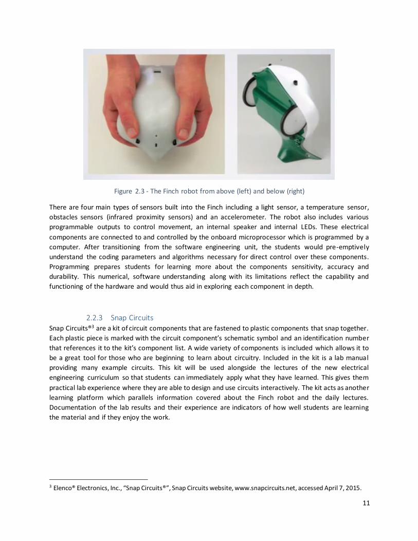
Figure 2.3 - The Finch robot from above (left) and below (right)
There are four main types of sensors built into the Finch including a light sensor, a temperature sensor,
obstacles sensors (infrared proximity sensors) and an accelerometer. The robot also includes various
programmable outputs to control movement, an internal speaker and internal LEDs. These electrical
components are connected to and controlled by the onboard microprocessor which is programmed by a
computer. After transitioning from the software engineering unit, the students would pre-emptively
understand the coding parameters and algorithms necessary for direct control over these components.
Programming prepares students for learning more about the components sensitivity, accuracy and
durability. This numerical, software understanding along with its limitations reflect the capability and
functioning of the hardware and would thus aid in exploring each component in depth.
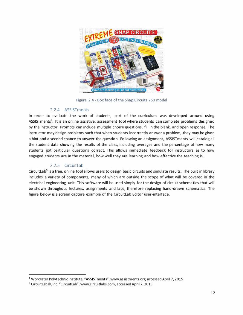
2.2.3 Snap Circuits
Snap Circuits®3 are a kit of circuit components that are fastened to plastic components that snap together.
Each plastic piece is marked with the circuit component’s schematic symbol and an identification number
that references it to the kit’s component list. A wide variety of components is included which allows it to
be a great tool for those who are beginning to learn about circuitry. Included in the kit is a lab manual
providing many example circuits. This kit will be used alongside the lectures of the new electrical
engineering curriculum so that students can immediately apply what they have learned. This gives them
practical lab experience where they are able to design and use circuits interactively. The kit acts as another
learning platform which parallels information covered about the Finch robot and the daily lectures.
Documentation of the lab results and their experience are indicators of how well students are learning
the material and if they enjoy the work.
3 Elenco® Electronics, Inc., “Snap Circuits®”, Snap Circuits website, www.snapcircuits.net, accessed April 7, 2015.
12
Figure 2.4 - Box face of the Snap Circuits 750 model
2.2.4 ASSISTments In order to evaluate the work of students, part of the curriculum was developed around using
ASSISTments4. It is an online assistive, assessment tool where students can complete problems designed
by the instructor. Prompts can include multiple choice questions, fill in the blank, and open response. The
instructor may design problems such that when students incorrectly answer a problem, they may be given
a hint and a second chance to answer the question. Following an assignment, ASSISTments will catalog all
the student data showing the results of the class, including averages and the percentage of how many
students got particular questions correct. This allows immediate feedback for instructors as to how
engaged students are in the material, how well they are learning and how effective the teaching is.
2.2.5 CircuitLab CircuitLab5 is a free, online tool allows users to design basic circuits and simulate results. The built in library
includes a variety of components, many of which are outside the scope of what will be covered in the
electrical engineering unit. This software will be used simply for the design of circuit schematics that will
be shown throughout lectures, assignments and labs, therefore replacing hand-drawn schematics. The
figure below is a screen capture example of the CircuitLab Editor user-interface.
4 Worcester Polytechnic Institute, “ASSISTments”, www.assistments.org, accessed April 7, 2015 5 CircuitLab©, Inc. “CircuitLab”, www.circuitlabs.com, accessed April 7, 2015

13
Figure 2.5 - CircuitLab user-interface screen capture
2.2.6 Lab Materials Lab supplies such as voltmeters, ammeters and ohmmeters were not included in the Snap Circuit kits. The
ones used for the labs were obtained by the school. They were previously used in an independent
electrical engineering elective until the course was dropped and were then placed into the school’s
inventory.

14
3. Project Strategy
3.1 Client Statement In starting this IQP, a definitive idea of the project outcome needed to be established. As Mrs. Reidy was
the main instructor for the course and would carry out future installments of the electrical engineering
curriculum, she and I confirmed what would be appropriate for enhancing the course unit. The following
client statement was produced as a result.
“This IQP will serve to develop an electrical engineering curriculum suitable for high
school students. The unit will be taught by David DiStefano using a variety of interactive
learning tools. Upon completion of the curriculum, students should be able to show an
understanding of basic electrical characteristics, the flow of energy, how energy may be
converted and how to design, build and troubleshoot basic circuits.”
3.2 Objectives and Constraints There are a number of objectives to be met in developing, implementing and teaching the electrical
engineering curriculum. These objectives are listed below as the main categories of design,
implementation and evaluation, and contain corresponding components that require completion as sub-
objectives.
1) Design
a) Lesson plans
b) Lab modules
c) Assessments
i) Pre-test
ii) Homework assignments
iii) Lab reflections
iv) Quizzes
v) Final test
2) Implementation
a) Present new curriculum
b) Teach daily lessons
c) Be available for outside communication
d) Take feedback
e) Document progress
3) Evaluation
a) Consider what worked & what did not
b) Evaluate how effective the curriculum was
c) Were the goals met
d) Future considerations

15
This project presents a few major constraints on the development and implementation of the curriculum.
Due to the interdisciplinary nature of the course, each unit cannot be explored too much in depth, but
must rather maintain a broad, introductory experience and relate well to the other units being taught.
Therefore, certain aspects of the engineering course in its entirety must be taken into consideration as
constraints for the development of the electrical unit. The unit is not free to explore any electrical-related
topic, but must fit the limited depth requirements of the IQP goals and objectives.
Since this IQP implements the first comprehensive electrical unit, there are certain time constraints that
determine when the unit is taught. Each unit may take more or less time to complete based on how active
students are in the material and whether or not projects are finished in time. While the engineering course
remains an experimental elective, this time constraint is an issue when it comes to planning the curriculum
and when certain lessons will take place. The students may also have field trips for other courses or other
events to attend, such as senior events, which may not allow the full class to be present. Flexibility in the
development and implementation of the curriculum will be necessary.
The materials used for this unit certainly serve as teaching tools and contribute to the practical experience
gained by the students, but they can also be limiting. The Snap Circuit lab kits have a rigid design and do
not contain too many components that allow for a variety of basic setups for introductory learning. The
electrical meters used from the school are analog meters with a dial and do not work as well as they
should. The textbook is also a helpful tool that covers sufficient basic principles of electrical engineering,
but does not offer much outside of those basics. The workbook, which covers the textbook material, can
be helpful in assessment and practice for the students, but also has a minimal scope.
3.3 Project Approach The general approach of this project starts with identifying what changes to the curriculum need to be
made and then designing the appropriate curriculum as a solution, followed by teaching and assessing
the unit. Lesson plans and assessment modules are used to accomplish a similar structured learning
style to that of WPI’s motto, “Lehr und Kunst” or “Theory and Practice.” The theory behind electrical
engineering is introduced to the students via the lesson plans where a specific topic is presented and the
associated concepts are discussed. Practice is achieve through circuit demonstrations, lab experiments,
assignments and other forms of assessment.
In order to fulfill the project’s objectives, the curriculum requires designing all of these materials and
planning accordingly. As will be discussed further in the report, however, lesson plans and assignments
were frequently altered due to time constraints and the varied learning rate of the students. On the first
day of the electrical engineering unit, students are assigned two online forms of assessment. One of them
is a “Class Survey” which gathers basic information about the students and what they’re hopes are for the
unit and how they perceive themselves as students. The second is a “Unit Pre-Test” which is used to
evaluate their understanding of the Finch robot and introductory electrical engineering concepts. This
pre-test is used to gauge how much the students already know about the unit’s material.
The development of the unit curriculum begins by reintroducing the Finch robot that was used in the
mechanical and software engineering units. This provides a smooth transition by building off knowledge
the students already have. By discussing the robot more in depth, students can learn more about the
sensors and mechanisms that are incorporated into its design. These can then be related to the other

16
components that they are aware of in the technologies they already use. The course can then be led into
individual lesson plans that discuss each sensor or transducer in depth. Along with covering these
components, the electrical characteristics of voltage, current and resistance hold a continuous focus as
well as understanding the flow and conversion of energy. The importance of these components is stressed
throughout the unit, elaborating on how electrical engineering can be used for automation and measures
of safety that can help people become more aware of their environment.
Once the foundation is set by introducing basic electrical engineering concepts, the unit progresses
towards practical applications. Specific components such as photoresistors and LEDs, among others,
become the central focus as they begin to be used in hands-on lab activities. Students are expected to
hold on to what they’ve read about within the course text as well as what’s lectured in the classroom so
they may be prepared for the lab and complete it accordingly.
Evaluating the students is a significant part of this project, as it determines how well the students are
learning and how effective the new unit curriculum is. After completing each lab experiment, students are
asked to do a lab write-up as an assessment. Mrs. Reidy suggested that a series of post-lab questions
would be most appropriate. The questions developed for this are open-response and ask for qualitative
answers as opposed to quantitative. The reason for this as also suggested by Mrs. Reidy is that qualitative
answers allow students to intuitively express their knowledge to see what they learned, without binding
them to a quantitative analysis. If students are able to understand the general working concepts of
electricity and energy within the lab circuit, then that is sufficient for Mrs. Reidy. Of course, the inclusion
of quantitative results can further aid in evaluating student’s understanding, but she does not require it.
Aside from the lab write-ups, students are assigned reading from the textbook which they must take notes
from. Showing their notes to Mrs. Reidy the next day earns them credit for the reading assignment and
lets her know how they are handling the reading of the new textbook. Three ASSISTment modules
assigned as homeworks are also used to further evaluate their learning throughout the unit.
Once the material to be taught in the unit is decided upon, the lessons are planned and set to a timeline.
As stated in the beginning of this section, there were several timing conflicts that caused shifting when
certain lessons were taught, however, the general layout of the material remained the same. The table
below shows the final calendar used for the course.

17
Table 1 – Final unit calendar
Date Material Covered
Day 1 - Wed 4/2 Introduction Cover syllabus, materials
Day 2 - Thurs 4/3 Lesson: Discuss Finch,
ASSISTments Pre-test, Student info
Day 3 - Fri 4/4 Lesson: Voltage, Current, Resistance, Power
Day 4 - Mon 4/7 Lesson: Tools, Measurements
Day 5 - Tues 4/8 Quiz / ticket-in,
Lesson: Diodes, Photoresistors, LEDs, Start LAB 1
Day 6 – Wed 4/9 Finish Lab 1
Day 7 – Thurs 4/10 Lesson: Thermistors, Motors
Start Lab 2
Day 8 – Fri 4/11 Lesson: Capacitors, Transistors Start Lab 3
Day 9 – Mon 4/14 Finish incomplete labs, Lesson: Officer Dan on Tazers
Day 10 – Tues 4/15 Review materials, prepare for test
Day 11 – Wed 4/16 Lesson: Vicor field trip,
Labs 2 & 3 due
Day 12 – Mon 4/28 Review, Educational Videos "Electric Nation", "High Voltage Power Lines", "Solar
Power Plant"
Day 13 – Tues 4/29 Full review
Day 14 – Wed 4/30 Final test

18
4. Curriculum Development
The curriculum is designed by starting with what the students already know about. The Finch robot is very
useful for this and as stated in the project approach, serves as a foundation and starting point for the
electrical engineering unit. By discussing some of the electrical components of the Finch, students are
meant to develop an appreciation for the inner-workings beneath the surface. From there, the curriculum
begins to explore the characteristics of voltage, current, resistance and power, as they pertain to the flow
of energy in circuits. Students then learn about the tools used to measure these characteristics as well as
how to use them in the lab setting. Additional components are introduced and students continue to learn
about the design possibilities within electrical engineering. A guest speaker visits the classroom later in
the unit to discuss their work and its relation to electrical engineering. A field trip to an electrical
engineering company is also setup for students to have more exposure to the field and experience a career
environment. Throughout the unit, students are continually assessed on what they’ve learned through
lab write-ups, homework assignments, quizzes and their notes. A final assessment is given in the format
of a test at the end of the unit after a class period of reviewing.
4.1 Lessons
4.1.1 The Finch
The first few lessons for the unit were taught using presentation format. The first lesson reviewed the
Finch and incorporated images of the robot in the presentation to recall its functions. The robot is capable
of detecting light using a photoresistor, temperature with a thermistor, and rotation with an
accelerometer. Programmable outputs include drive motors and a speaker. Once these components are
introduced and linked to corresponding function of the robot, it is important to relate the physical
attribute that is being measured and converted to an electrical signal, or vice versa. Students learn about
these components as well as others over the first couple weeks of the unit.
4.1.2 Basic Electrical Concepts In order to understand the working concepts of these components, students are taught about voltage,
current, resistance and power during the second lesson presentation. This second lesson’s main goal is to
establish the relationship between these concepts through using Ohm’s Law and Watt’s Law. The
measuring of these is also introduced as well as the idea that the actual measured value does not
necessarily equal the nominal value identified.
Voltage is taught to the students with the definition as “the amount of pressure causing the flow of
electrons; expressed as electromotive force (EMF). It is the potential difference in electric potential energy
between two points.” The mathematical notation for voltage is shown to the students as either:
V - voltage, ∆V – voltage difference, E – electromotive force (EMF)
with the SI Units of Volts. Direct Current (DC) and Alternating Current (AC) are briefly discussed with the
students, relating household batteries to DC and the voltage of outlets and transmission lines to AC.
Schematic symbols for voltage sources are shown using the following.

19
Figure 4.1 – Voltage schematic symbol
The polarity of these sources is discussed and how to measure the voltage using a voltmeter.
Next, the concept of electrical current is introduced as the flow of electrons through a medium where
conventional current is the perspective of positive charge moving to negative. This lesson continues to
define the concepts of voltage, current, resistance and power and elaborates on their significance within
the engineering field as well as safety limitations, examples and applications.
The relationship between these three concepts is brought together with the introduction of Ohm’s Law
and Watt’s Law.
Ohm’s Law V = I x R [Voltage = Current x Resistance] [1]
Watt’s Law P = I x V [Power = Current x Voltage] [2]
These two equations become the students most frequently used tools throughout the unit as they are
provided problem circuits with one of the variables missing and must solve for the unknown parameter.
The basic circuit diagram in Figure 4.2 is a sample template for filling in two of the parameters, either
voltage, current or resistance.
Figure 4.2 – Circuit template for using Ohm’s Law and Watt’s Law
Students may then be asked to calculate the power in Watts experienced by the resistor.
20
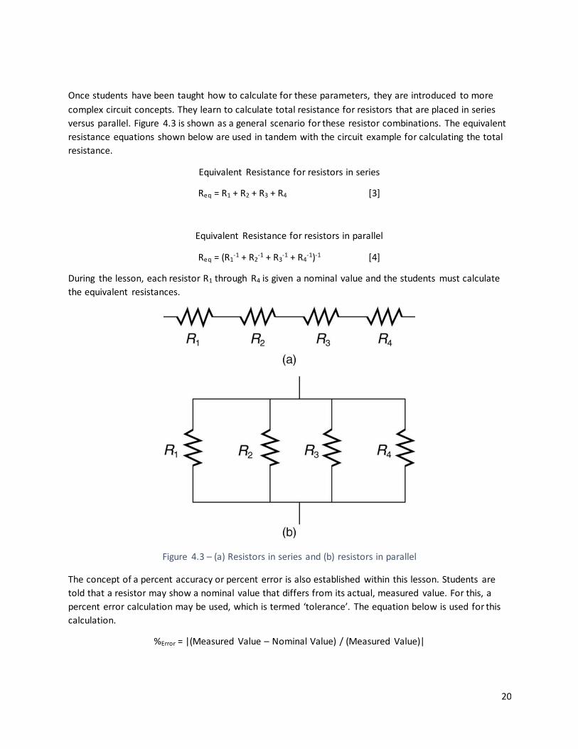
Once students have been taught how to calculate for these parameters, they are introduced to more
complex circuit concepts. They learn to calculate total resistance for resistors that are placed in series
versus parallel. Figure 4.3 is shown as a general scenario for these resistor combinations. The equivalent
resistance equations shown below are used in tandem with the circuit example for calculating the total
resistance.
Equivalent Resistance for resistors in series
Req = R1 + R2 + R3 + R4 [3]
Equivalent Resistance for resistors in parallel
Req = (R1-1 + R2
-1 + R3-1 + R4
-1)-1 [4]
During the lesson, each resistor R1 through R4 is given a nominal value and the students must calculate
the equivalent resistances.
Figure 4.3 – (a) Resistors in series and (b) resistors in parallel
The concept of a percent accuracy or percent error is also established within this lesson. Students are
told that a resistor may show a nominal value that differs from its actual, measured value. For this, a
percent error calculation may be used, which is termed ‘tolerance’. The equation below is used for this
calculation.
%Error = |(Measured Value – Nominal Value) / (Measured Value)|

21
4.1.3 Tools and Measurements
The third lesson covers tools used within electrical engineering that are used for measuring the
parameters introduced in the previous lessons. Students have access to voltmeters, ammeters and
several multimeters to measure resistance. These tools are discussed in a presentation lesson format
with sample circuit diagrams so the position of the meter probes may be demonstrated. Once the
students have visually observed the process of measuring voltage across a component, the current
through a circuit, or the resistance of a component.
4.1.4 Diodes, Photoresistors, LEDs This lesson and the ones that follow are taught without a presentation, but rather utilize the classroom
whiteboard. The diode is introduced to the class as a component that rectifies current, allowing current
to flow in one particular direction. Other characteristics of the diode are briefly addressed such as
threshold voltage. The LED is then discussed, establishing that it is a diode that emits light as a result of
the current through it. The photoresistor is then introduced as a resistor that varies its resistance
measurement based on the light intensity that is experienced. These components are drawn on the
whiteboard with their schematic symbols along with the variable relationships (voltage, current,
resistance) that are characteristic to each. The components are each drawn in basic circuits so their
function can be further discussed in an example. Nominal values are assigned to a voltage source and
any resistors, then the component behavior is discussed as well as how it reacts to changes in circuit
voltage, current or resistance.
After this course lesson, students begin working on Lab 1, “Measurements”, which covers the material
that was learnt in the previous lesson electrical measurement tools.
4.1.5 Thermistors, Motors Students have the beginning of this day’s lesson to start working on Lab 2, “LEDs and Photoresistors”,
which gives them practical experience working with the components introduced in the previous lesson.
The last quarter of the class period is used to introduce the thermistor and the motor. Students are
taught that the thermistor is a resistive sensor that varies its resistance as a function of change in
temperature. The two types of thermistors, positive and negative temperature coefficient thermistors,
are briefly discussed along with their applications and reasons for selection. The motor is discussed in
some detail, starting with how an alternating current induces an alternating magnetic field about a wire
coil. The alternating magnetic field is experienced by magnets. The opposing magnetic fields induce
rotational displacement about the axle in relation to its housing. The students do not use the thermistor
and motor in a lab experience, but they are given the opportunity to use the components in the Snap
Circuits kit during their free time to observe their use.

22
4.1.6 Capacitors, Transistors This lesson introduces the capacitor and transistor. The capacitor is discussed as a component that
stores electrical charge. Since the unit is introductory and focusing on DC circuitry, the AC function of
the capacitor is not discussed with its filtering application. The charging effect of the capacitor is taught
with its relationship to time. The charging equation for capacitor voltage is derived quickly for the
students, but they are not encouraged to learn or memorize the equation, instead they must simply
recall that the relationship is exponential, that the capacitor voltage increases with a steep rate at first,
then approaches the final voltage asymptotically. The discharging effect is then discussed similarly, with
the voltage decreasing steeply at first, then approaching 0V. The capacitor schematic symbol is drawn
with its polarity labeled within a basic RC (resistor-capacitor) circuit. The flow of current is drawn flowing
to the capacitor with the capacitor filling with charge and increasing the voltage across its terminals.
Once the capacitor has reached the final voltage, it cannot receive any more charge and thus the current
slows to zero amps. The visual representation of this behavior is drawn similarly for the discharge of the
capacitor.
The transistor is then introduced for its simply application as an electronic switch, capable of opening or
closing the pathway of current within the semi-conductive material. The transistor schematic symbol is
drawn in an example circuit to demonstrate how the component is used to control the operation of a
circuit.
Following the lessons on these components, the students are allotted time to complete Lab 3, “RC
Circuits and Transistors” which exhibit the charging and discharging of a capacitor through a resistor as
well as the switching operation of a transistor. The charge of the capacitor is dissipated through an LED
so that students may visually see the function and flow of current within the circuit.
4.1.7 Guest Speaker After the main lessons of the unit have been taught, the class has time to review material and complete
unfinished labs. One of the last days of the unit is used to invite a guest speaker to visit the class and
discuss their knowledge of electrical engineering. Mrs. Reidy suggested inviting someone who would be
able to discuss an immediately interesting topic. For this, she polled the students and found that they
were very interested in understanding the use of Tazers, as the school police officer carries one on his
belt. Officer Dan was invited to discuss the specifications of the Tazer, how it works and how to use it.
This lesson allows for discussing the resistance of the human body and the lethal electrical limitations in
relation to the power of the Tazer. Following Officer Dan’s visitation, students must write a short
summary of what they learned and a reaction in order to receive credit for the day.

23
4.1.8 Field Trip Mrs. Reidy has scheduled a class field trip to Vicor Corporation in Andover, MA. The company is an
electrical engineering company that designs, manufactures and tests power regulation components. In
visiting the local company, students are able to talk to electrical engineers about the nature of their
work as well as see their laboratories and facilities. Students must write a brief reaction paper to receive
credit for the day.
4.2 Labs The labs are designed to give the students practical experience of what they’ve learned about during the
lessons. Students use the Snap Circuits kit to construct various circuits and use voltmeters, ammeters,
ohmmeters and additional wires to complete the lab. A guided lab manual for each lab experience
informs the student of the objective as well as step by step instructions. The lab manual includes tables
for students to enter data as well as open response questions for them to qualitatively note
observations of circuit behavior. Students must do a post-lab write-up in the form of an ASSISTments
open response questionnaire. Resort to the appendices to see these lab manuals and lab write-ups.
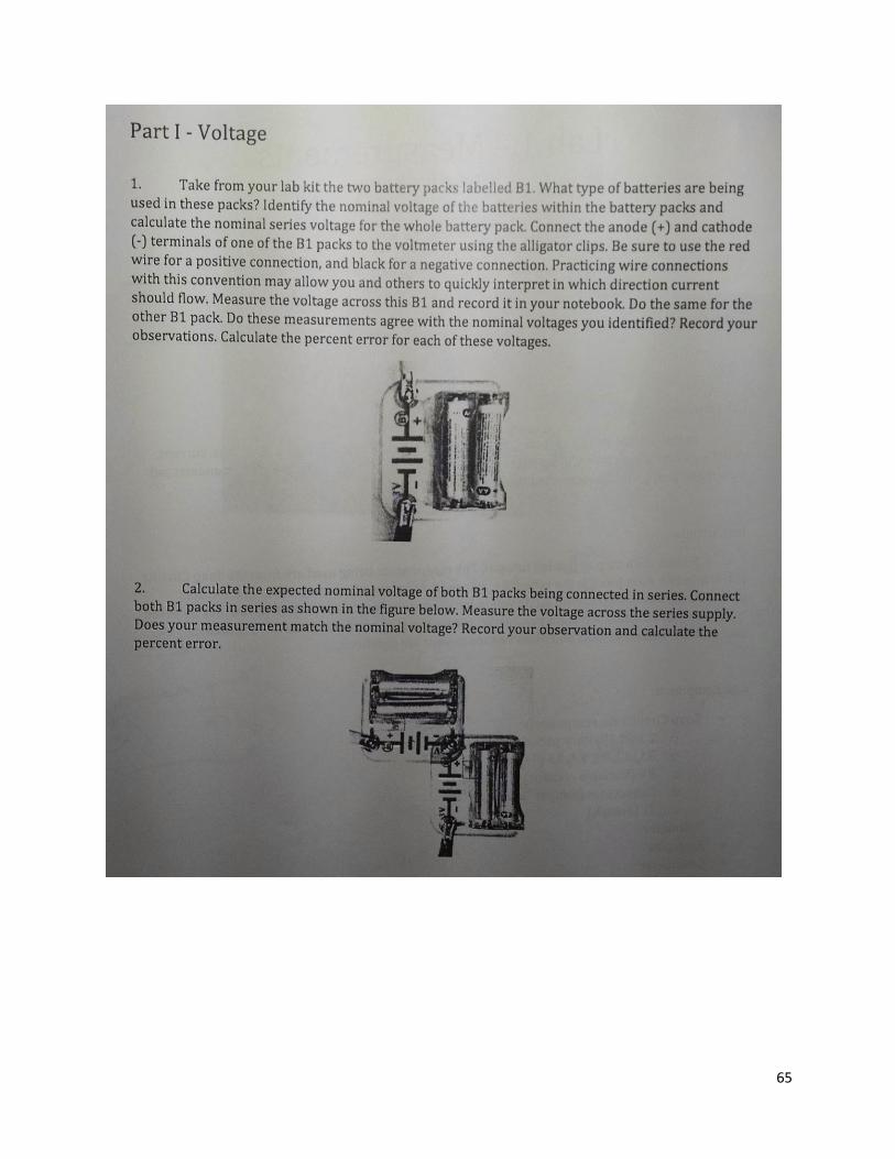
4.2.1 Lab 1 – “Measurements” This is an introductory lab to expose students to methods of measuring voltage, current, resistance and
calculating power. They begin by measuring the voltage across one battery pack and then two battery
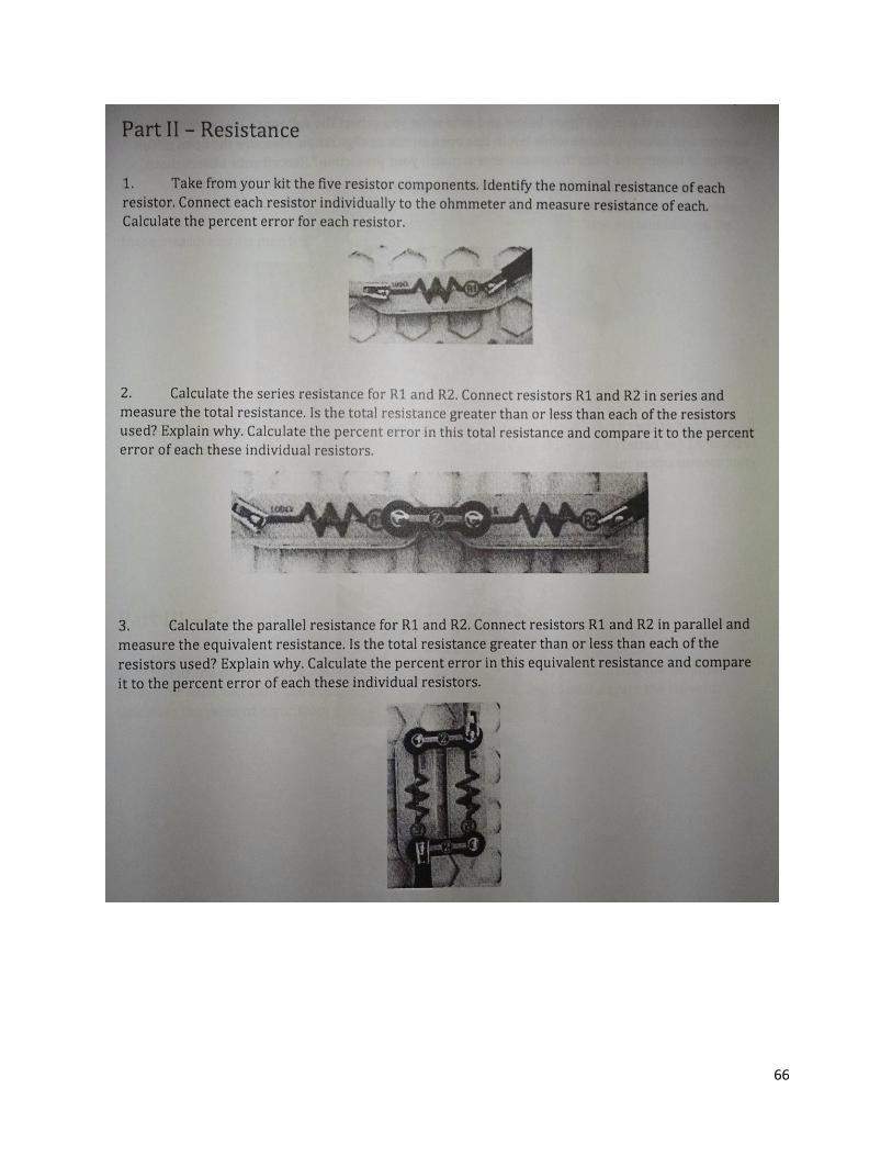
packs in series. In the second part of the lab, five resistors are used and are noted for their nominal
value and then measured independently. Students place the resistors in a few combinations to measure
and record the total resistance. They calculate the percent error. In the third part of the lab, the current
is measured at certain nodes for a few circuits. Lastly, the manual introduces potentiometers as variable
resistors with a lever (the ones used in the kit). Students measure its resistance as the lever is moved,
and then place it in a circuit where they measure the change in current as the lever is moved.
4.2.2 Lab 2 – “LEDs and Photoresistors” The second lab gives students the opportunity to work with LEDs and photoresistors as they were taught
in the previous lesson. The LED is powered in a circuit in series with a potentiometer where the voltage
across the LED and the potentiometer are measured while the lever is moved. The same is done for
measuring current through the circuit. Next, the potentiometer is replaced by the kit’s photoresistor
which acts similarly. To change its resistance, students use a flashlight to expose the photoresistor to
direct light, and then cover the photoresistor so it receives no light. The voltage across each component
is measured along with the current in the circuit.
4.2.3 Lab 3 – “RC Circuits and Transistors”
In the third lab, students construct circuits with capacitors, resistors, LEDs and transistors. The first
circuit charges a capacitor through an LED and resistor in series. As the capacitor charges, the LED begins
to dim. The circuit is designed to demonstrate the charging effect of the capacitor in relation to the f low
of current in the circuit via the brightness of the LED. Next, a transistor is added so the control of current
can be observed. An LED is used again so students may observe the effect.

24
5. Implementation & Outcome
Upon implementation of the curriculum, a number of challenges were experienced. Some of these
challenges were minor and could be overcome such as certain planning challenges, while other challenges
such as with ASSISTments, could just be bypassed. These are alluded to in the Challenges subsection. Aside
from the challenges, there was a lot of positive feedback from students and Mrs. Reidy as to how the
curriculum was designed and taught. Each challenge faced was looked at as a learning opportunity that
could be avoided in future curriculum design. This is discussed in the Positive Outcomes subsection.
5.1 Challenges
5.1.1 Scheduling Conflicts
The main difficulties in implementing the curriculum were related to the scheduling and planning of the
lessons. The unit began later than originally planned and the dates of lessons needed to be shifted.
Upon starting the unit, there was not enough time to teach everything within the lesson and also take
questions and give examples. This was not fully accounted for when designing the curriculum. Mrs.
Reidy had suggested planning extra time and to keep the lesson shorter to leave time for questions and
conversation to drive the lesson home, however this was underestimated. Because of this, the first few
lessons were taught impartially, causing the subsequent days to include material from the previous
lessons. Some of the teaching material was removed from the lessons in order to optimize the time for
teaching and student discussion. After the first week, a balance was met.
5.1.2 Teaching Material Throughout the unit, students had complaints about reading the new textbook because it lacked
excitement. It did not seem to be as animated and was more of a nuisance for students to read if they
were uninterested. The lessons aimed to make up for this excitement by becoming more interactive,
asking students for examples of where they’ve witnessed certain components in their own electronics,
or having them design their own basic circuits and walk the class through them, and even using the lab
kits for hands-on interactive experience.
5.1.3 ASSISTments
The ASSISTments became a minor problem for only a few students, where some of the assessment
modules did not work for them. During one of the visits to the high school, I met another teacher who
also used ASSISTments for his class. He believed that ASSISTments has a lot of potential, but had seized
using it because it lacked robustness and did not fulfill what he was looking for. It was more of a
challenge for teachers to design the modules than it was for students to use the modules. I found this to
be very true as well. It took a significant amount of time to design the modules, and since the majority of
the assessments were open-response format for qualitative answers, the class could not be graded by
the built-in calculator. Instead, I reviewed each response for each student which was very time
consuming. Mrs. Reidy disliked the use of the online software as well. She preferred using a written
exam format that could be multiple choice or fill in the blank where students could draw on circuit
diagrams directly or take notes on the sides of the pages. Overall, the ASSISTments was a unique tool to
incorporate into the curriculum, but would understandably not be used in future iterations of teaching
the curriculum.

25
5.1.4 Lab Experiences Students found the lab modules to be the most helpful in understanding how current flows through a
circuit and how it relates to the voltage across components and the resistances thereof. The only thing
that they did not like about the labs was the rigidity of the lab kit. The kit is designed by placing smaller
electrical components on larger plastic pieces that fit together in a strict format. Perhaps in the future,
standard through-hole components may be used with a circuit breadboard so that students may
5.2 Positive Outcomes
5.2.1 Student Experience As a new unit for the curriculum, the students are able to engage in material that they are unfamiliar
with but are prepared to learn. Towards the start of the unit, students had no idea what electrical
engineering fully entailed and throughout the unit, they continued to show amazement to the
theoretical analysis of circuits with mathematics and how they are made practical with the science of
materials. By the end of the unit, students had a much better understanding of electrical engineering
and some were even considering pursuing it as a major in higher education.
5.2.2 Teacher Experience
This was also a great learning experience for Mrs. Reidy and myself. She was able to learn a lot more
about this field of engineering, allowing her to include this introductory information in future iterations
of the course. She was a student of the curriculum, but also taught the same curriculum to a class of
another course period shortly after learning the material herself. This was also a great opportunity for
me to reflect on all that I’ve learned as an electrical engineering college student. Putting together
materials solidified my understanding and teaching it offered me public speaking skills.
5.2.3 General Outcome Overall, the unit was taught while receiving continuous feedback from students and Mrs. Reidy. The unit
reached its goals in successfully designing the materials and teaching them accordingly. The lab
experiences were found to be the most helpful in relaying the concepts to the students. Finally, Mrs.
Reidy and I were introduce the new unit to replace the previously taught two-day electrical engineering
unit, and students were able to learn something new as a potentially decisive factor for a future
education in engineering.

26
6. Conclusion
This project began with the objectives of designing an electrical engineering unit curriculum. The
appropriate lesson plans were designed along with lab modules and homeworks to assess the students.
Lesson plans were frequently modified to fit the allocated time periods in order to allow time for students
to ask questions and for re=explanation of lesson material. Students were able to take away the key
concepts necessary to continue through the course and were assessed with homework assignments of
reading and taking notes, ASSISTments based homework assignments and lab reflections, and pre- and
post-test. The design of these materials were difficult at first because I could not foresee how well
students would learn the material in order to advance to further material. Once the teaching of the unit
began, however, I was able to observe the learning rate of the class and adjust the materials accordingly.
I maintained strong communication with the class, making myself available via email, which students often
took advantage of. Students always announced what concepts they had trouble learning and Mrs. Reidy
and I did our best to get back to the students in a timely manner so they could complete their assessments.
For this, students gave good feedback in that we were doing a good job in tailoring our explanations to
the student so they could understand. By the end of the unit, it was found that the labs were the most
significant learning experience for the students because it provided them with the necessary hands-on
experience to understand the theoretical concepts that are in play with circuitry. The use of the textbook
and workbook will have to be re-evaluated by Mrs. Reidy, as the students did not favor the material too
much, as well as the use of ASSISTments. Further efforts would need to be invested to perfect the use of
this online tool, however, the gains in using the tool may not outweigh the work of its development.
Overall, students and teachers accomplished all that the unit was designed for, and the curriculum was
effective in boosting the material and experience for the electrical engineering unit. Future improvement
to the unit would include a more flexible schedule so that lessons were less structured and more free-
flowing. This would allow lessons to be taught a bit more independently. ASSISTments would not likely be
used again, and instead be replaced by take-home, printed assignments. The lab kits may be used for
demonstration purposes in the future, but may be replaced by the traditional, through-hole components
for the in-class labs. Further improvement would be evaluated by Mrs. Reidy and the students as the
course continues.

27
7. References
[1] BirdBrain Technologies, LLC., “The Finch”. The Finch website, www.finchrobot.com, accessed
April 7, 2015.
[2] Brown et. al, Engineering Fundamentals: Design, Principles, and Careers. (Tinley Park, IL: The
Goodheart-Willcox Company, Inc., 2014).
[3] Elenco® Electronics, Inc., “Snap Circuits®”, Snap Circuits website, www.snapcircuits.net,
accessed April 7, 2015.
[4] Worcester Polytechnic Institute, “ASSISTments”, www.assistments.org, accessed April 7, 2015
[5] CircuitLab©, Inc. “CircuitLab”, www.circuitlabs.com, accessed April 7, 2015

28
8. Appendix
8.1 ASSISTments
8.1.1 Class Survey

29

30

31
8.1.2 Unit Pre-Test

32

33

34

35

36

37

38

39
8.1.3 Chapter 8 Review – (EFW, Page 101)

40

41

42
8.1.4 HW – Voltage

43

44

45

46

47
8.1.5 HW – Current

48

49

50

51

52

53

54
8.1.6 Lab 1 Reflection

55

56

57
8.1.7 Lab 2 Reflection

58

59
8.1.8 Lab 3 Reflection

60

61

62

63

64
8.2 Lab Assignments
8.2.1 Lab 1
65
66

67

68
69

70

71

72

73

74
8.2.2 Lab 2

75

76

77

78

79

80

81
82

83
8.2.3 Lab 3

84

85

86

87

88

89