electrical - ekahroba.com ele 221.pdf · • 1 "master programmable logic controller"...
TRANSCRIPT

Exploration & Production
This document is the property of Total. It must not be stored, reproduced or disclosed to others without written authorisation from the Company.
GS ELE 221.doc
GENERAL SPECIFICATION
ELECTRICAL
GS ELE 221
Power Distribution Control System PDCS
01 09/03 Change of Group name and logo
00 03/01 First issue
Rev. Date Notes

Exploration & Production
General Specification Date: 09/03
GS ELE 221 Rev: 01
This document is the property of Total. It must not be stored, reproduced or disclosed to others without written authorisation from the Company.
GS ELE 221.doc Page 2/56
Contents
1. Scope .......................................................................................................................4
2. Reference documents.............................................................................................4
3. General.....................................................................................................................53.1 Description...................................................................................................................... 53.2 Environmental data ......................................................................................................... 63.3 Electrical service conditions ............................................................................................ 73.4 Deviations to specification............................................................................................... 7
4. Electrical control philosophy .................................................................................74.1 Electrical network description.......................................................................................... 74.2 General........................................................................................................................... 74.3 Power generation control philosophy .............................................................................. 84.4 Power distribution control philosophy .............................................................................. 84.5 Information to be exchanged......................................................................................... 13
5. Power Distribution Control System equipment..................................................135.1 PDCS configuration ...................................................................................................... 135.2 Equipment functions ..................................................................................................... 145.3 Reliability ...................................................................................................................... 155.4 Hardware requirements................................................................................................. 155.5 Software requirements .................................................................................................. 175.6 Communication networks requirements (Field bus)....................................................... 17
6. Inspection and testing ..........................................................................................186.1 Factory acceptance tests (Option 11)............................................................................ 186.2 Tests after erection on site (Option 12) ......................................................................... 196.3 Test reports................................................................................................................... 19
7. Limits of supply.....................................................................................................19
8. Documents to be supplied by the SUPPLIER .....................................................19
9. Services .................................................................................................................219.1 Project execution .......................................................................................................... 219.2 System analyses, development and configuration......................................................... 22

Exploration & Production
General Specification Date: 09/03
GS ELE 221 Rev: 01
This document is the property of Total. It must not be stored, reproduced or disclosed to others without written authorisation from the Company.
GS ELE 221.doc Page 3/56
9.3 Documents supplied by COMPANY.............................................................................. 22
10. Abbreviations ........................................................................................................23
Appendix 1 PDCS Structure ....................................................................................24
Appendix 2 Typical arrangement ............................................................................26
Appendix 3 Input/Output list....................................................................................27
Appendix 4 Screen - Typical views .........................................................................31
Appendix 5 HV & LV power generation - Logic diagrams - Typicals ...................33
Appendix 6 HV logic diagrams - Typicals...............................................................43
Appendix 7 Emergency switchboard - Incomers - Logic diagrams - Typicals....47
Appendix 8 Main LV switchboard - Logic diagrams - Typicals ............................50
Appendix 9 Load shedding - Logic diagrams - Typicals.......................................54
Appendix 10 Alternates and options ........................................................................56

Exploration & Production
General Specification Date: 09/03
GS ELE 221 Rev: 01
This document is the property of Total. It must not be stored, reproduced or disclosed to others without written authorisation from the Company.
GS ELE 221.doc Page 4/56
1. ScopeThis specification defines the minimum requirements for the design, manufacture, materials,software, inspection and test of the electrical control system equipment (Power DistributionControl System - PDCS) to be installed on the offshore or onshore COMPANY electricalfacilities.The SUPPLIER shall ensure all the coordination required with its subcontractors.The SUPPLIER shall be responsible for supplying the system complete in every way and shalladvise the COMPANY of any deviations/omissions in the specification prior to placement of thePurchase Order.
2. Reference documentsThe reference documents listed below form an integral part of this General Specification. Unlessotherwise stipulated, the applicable version of these documents, including relevant appendicesand supplements, is the latest revision published at the EFFECTIVE DATE of the CONTRACT.Design, materials and performance of the PDCS shall be in accordance with the current editionof the following documents:
Standards
Reference TitleIEC 61000-1-2-3-5 Electromagnetic compatibility (EMC)IEC 61131 Programmable controllers
Applicable recognized standards (UTE, BS, VDE, etc.) and codeswhere IEC publications have not yet been issued
IEC 332
Professional Documents
Reference TitleNot applicable
Regulations
Reference TitleEMC (Electromagnetic compatibility) European Directive89/336 EEC and 92/31 EEC and 93/68 EEC (CE marking)
Codes
Reference TitleNot applicable

Exploration & Production
General Specification Date: 09/03
GS ELE 221 Rev: 01
This document is the property of Total. It must not be stored, reproduced or disclosed to others without written authorisation from the Company.
GS ELE 221.doc Page 5/56
Other documents
Reference TitleGeneral single line diagramHV single line diagrams (*)LV single line diagrams (*)UPS AC & DC single line diagrams (*)
Total General Specifications
Reference TitleNot applicable
3. General
3.1 DescriptionThe PDCS shall be suitable to manage power supply supervision of the whole electricalfacilities.For that purpose, it shall be designed to carry out the following principal tasks:
• Control of power distribution and power generation systems
• Data acquisition and display of power generation and power distribution parameters
• Load shedding
• Re-acceleration and restarting
• Source automatic transfer
• Data storage and reporting
• Interface with Process Control System.PDCS shall also be designed to allow additional software and hardware facilities for futureextension.This Power Distribution Control System (PDCS) shall, in conjunction with the relevant ProcessControl System (PCS) facilitate the control and the supervision of the power generation anddistribution systems.The main purpose of the PDCS is to be an aid to operators. Furthermore, failure of thePDCS must not stop operation of any part of the power generation and distributionsystems.The PDCS shall be constituted with one Front End Processor (FEP) and a Visual Display Unit(VDU), and PLC’s.The PDCS shall be based upon either:
• 1 "master Programmable Logic Controller" (non redundant design: option 1)
• 2 "master Programmable Logic Controller" (redundant design: option 2).

Exploration & Production
General Specification Date: 09/03
GS ELE 221 Rev: 01
This document is the property of Total. It must not be stored, reproduced or disclosed to others without written authorisation from the Company.
GS ELE 221.doc Page 6/56
The PDCS shall be designed according to following alternates and options:
3.1.1 AlternatesA 1 Switchroom monitored from FEP located in Control RoomB 2 Switchrooms or more monitored from FEP located in Control RoomC 1 Switchroom monitored from FEP located in Switchroom
3.1.2 Options1 1 Master Programmable logic controller (non redundant PLC)2 2 Master Programmable logic controllers (redundant PLC's)3 Automatic synchronization4 Manual synchronization5 Power calculation for load shedding initiation6 Automatic source transfer7 Load shedding8 Reaccelaration and restarting9 Existing plant monitored from PDCS10 Management and coordination with equipment supplied by others11 Factory tests with all switchboards, panels, etc. connected12 Tests after erection on site.Note: See Appendix 10 for option selectionIf option 10 is required, the SUPPLIER shall be responsible for the implementation of allapplication software including the management, coordination, between his own equipment andany further equipment referred to in this specification supplied by others.The master PLC can be interfaced to 1 (or more) slave PLC located in secondarysubstation/switchroom.Master PLC's and slave PLC's shall be interfaced via serial links.The PDCS shall be capable of interfacing with all the equipment of the power generation anddistribution systems (i.e. control panels of turbine/emergency generating sets, HV, LVswitchboards and other switchgear, UPS cubicles, etc.).The structure of the PDCS with equipment relevant to each room is shown on the diagrams ofAppendix 1.
3.2 Environmental dataPDCS equipment shall be installed inside air conditioned electrical, technical or control room.Nevertheless, the equipment shall be capable of operation at a 40°C ambient temperaturewithout deleterious effects. As a minimum cubicles and cabinets shall be fitted with heaters;electronic cards shall be double varnished.The minimum degree of protection of enclosures shall be IP 21 (according to IEC 60529).

Exploration & Production
General Specification Date: 09/03
GS ELE 221 Rev: 01
This document is the property of Total. It must not be stored, reproduced or disclosed to others without written authorisation from the Company.
GS ELE 221.doc Page 7/56
3.3 Electrical service conditionsThe available voltages for the equipment shall be:
• 230 V AC from UPS for Front End Processors, visual displays units, printer(s) and clockreference system
• 230 V AC from UPS or 48 V DC unearthed from batteries for master(s) and slave(s)PLC's.
Voltage variations shall be kept within the following limits:
• 230 V AC - UPS ± 1% steady state conditions
± 10% - 15% transient conditions
• 48 V DC ± 2% steady state conditions
• Frequency 50 or 60 Hz ± 0.5% steady state conditions± 5% transient conditions
3.4 Deviations to specificationNo deviation from the requirements of this specification are allowable unless itemised in theSUPPLIER Bid and subsequently agreed within the Purchase Order or Order SupplementDocuments.Should this specification conflict with requirements of the listed standards or COMPANYspecifications, the SUPPLIER shall request clarification from the COMPANY at the time oftendering.
4. Electrical control philosophy
4.1 Electrical network descriptionElectrical networks are generally divided into two parts:
• The power generation system
• The power distribution system.The power generation is generally composed of turbine generators, gas engine generators,diesel generators, national grid or a combination of both of them with associated transformers.The voltage level is generally 400 V, 6600 V, 11000 V, 22000 V or 33000 V, the number oftransformers is variable.The power generation equipment is connected to the power generation switchboard. The powerdistribution is formed by a certain number of step-down transformers supplying LV switchboardseither composed of two bus sections or one for final distribution. The voltage level is generally6600 V for large motors and 400 V for other motors.
4.2 GeneralThe power distribution control system shall be achieved by means of one dedicated system.This dedicated system shall, in conjunction with the relevant Process Control System (PCS orDCS), facilitate the control and supervision of the power generation and distribution systems.

Exploration & Production
General Specification Date: 09/03
GS ELE 221 Rev: 01
This document is the property of Total. It must not be stored, reproduced or disclosed to others without written authorisation from the Company.
GS ELE 221.doc Page 8/56
For small projects and/or projects with only one low voltage level (e.g. 400 V) and afterCOMPANY approval, the possibility of integrating the PDCS within the PCS shall be studied.As a minimum, the PDCS shall be based upon one master PLC, in a non redundantconfiguration installed in the main control room or main electrical switchroom, provided with oneFront End Processors (FEP) including VDU'S (2) and key boards. Slave PLC'S (if required) innon redundant configuration shall be installed in each substation.All equipment of PDCS shall be interfaced by means of an appropriate communication network.Note: When required, in particular for large onshore plants, complementary design such as:
• Additional FEP or printer
• Slave PLC'S in redundant configuration may be required.
In addition to the here above design, the PDCS shall be capable of interfacing with all theequipment of the power generation and distribution systems (i.e. control panels of turbinegenerators, emergency generator sets, HV and LV switchboards and associated switchgear,UPS, PCS, etc.).
4.3 Power generation control philosophyTurbine or gas engine generator sets (when applicable) shall be capable of operating withouthelp from the PDCS.Only status, measurements, alarms, faults and relevant calculations shall be exchangedbetween the PDCS and the generator sets' control panels.In general, FEP will be installed in the main control room.The PDCS shall be interfaced with normal and emergency generator sets to allow autosynchronization of the main circuit breakers (option 3) and normal stop of emergency set(s).Manual synchronization shall be also provided (option 4).When required (option 5), the PDCS shall be capable of calculating the maximum allowablepower of turbine generator sets (spinning reserve), depending on ambient conditions (mainlytemperature) in order to initiate the load shedding in the most stringent conditions.The following is for information only and is not part of PDCS supply. A load sharing system ofthe PLC type shall be foreseen in the turbine generator set control panels to regulate, understeady state conditions, the flow and sharing of active and reactive power and system voltageand frequency of the power plant in accordance with the total system demand of each turbinegenerator.The turbine generator voltage regulators will control, independently from the PDCS, thegenerator excitation according to the normal system voltage setpoint.The behaviour following transient changes such as sudden load application or rejection, systemfaults or loss of a power supply source (generator) will be determined by the turbine generatorspeed control and the other system stability factors.
4.4 Power distribution control philosophy
4.4.1 GeneralThe PDCS shall be provided with a clock system (for recording the date and time of occurrenceof each event) controlled by the relevant master PLC.

Exploration & Production
General Specification Date: 09/03
GS ELE 221 Rev: 01
This document is the property of Total. It must not be stored, reproduced or disclosed to others without written authorisation from the Company.
GS ELE 221.doc Page 9/56
Each local slave PLC, Incomer Management Unit (IMU), Tie Management Unit (TMU), Feedermanagement Unit (FMU), Motor Management Unit (MMU), turbine, gas engine or emergencygenerator set control panel, etc. shall be fully synchronized with this relevant central clock withrespect to date and time.In addition, the PDCS shall be designed to be synchronized by a central Clock ReferenceSystem (CRS) provided to synchronize the PDCS and PLC'S and also the associated andconnected equipment.Absolute time shall be given by an additional GPS or equivalent system.
4.4.2 Supervision of distribution systemThe PDCS shall facilitate the supervision of the power generation and distribution systems(including overview of the turbine generators), and shall show via mimics on the VDU the statusof:
• HV circuit breakers
• Main LV circuit breakers, (Incomers, Tie and Main outgoer)
• Turbine or gas engine generators
• Homopolar generator contactors
• Transformers
• Emergency diesel generator(s)
• Other equipment, such as UPS, HVAC panels, etc. (if required)
• PDCS architecture.The graphics shall be in the form of animated single line diagrams.Equipment shall be shown as green when de-energised and as red when energised.If required electrical facilities shall be divided into substations, and at least one graphic displayshall be provided for each substation.
4.4.3 Protection relays and FMUAll protective relays shall be of the following types:
• Incomer Management Unit (IMU) for HV and LV switchboards
• Tie Management Unit (TMU) for HV and LV switchboards
• Feeder Management Unit (FMU) for HV switchboards
• Motor Management Unit (MMU) for HV switchboards
• Separate protection for turbine or gas engine driven synchronous generators, in dedicatedprotection panels
• Separate protection for diesel driven synchronous generator (EDG 400 V).These microprocessor based protection relays shall include facilities for communication with theMaster PLC's of the PDCS. These communications shall be achieved via serial links withJbus/Modbus protocol RS485.It shall be possible via the PDCS to interrogate each of these protective relays.

Exploration & Production
General Specification Date: 09/03
GS ELE 221 Rev: 01
This document is the property of Total. It must not be stored, reproduced or disclosed to others without written authorisation from the Company.
GS ELE 221.doc Page 10/56
• For each voltage level, status, alarms and measurements shall be sent to the Master PLCvia serial links.
4.4.4 Event recording and alarmingThe PDCS shall record all significant events, alarms and actions (from Protection managementunit) which occur in the power generation and distribution systems, with a discriminationbetween events of 10 ms or less. Time stamping shall be achieved with a discrimination of10 ms. This resolution shall be guaranteed for the whole plant.The SUPPLIER shall supply dedicated digital inputs for this application.All faults shall be discriminated and correctly recorded in date and time.It shall be also possible to assign priorities (and change them) to each event, e.g. record only,low priority alarm, high priority alarm.Only alarms and faults shall be acknowledged. No acknowledgment is required for status.Each event and further action (including operator acknowledgment), whether automaticallyinitiated or by operator, shall be recorded and stored in event history files in permanent memory(e.g. hard disk), with the date and time of occurrence clearly indicated. Alarms shall bedisplayed on a VDU alarm page, and shall remain until acknowledged. The printer is normallydedicated to event recording as soon as an event appears, but it shall be possible to retrieve,display and print the event history file for each substation or for the complete system.Event recording shall comply with the data logging requirements but shall also be designed tosupply the following additional functions.Event recording shall be normally “in line” with the printer, nevertheless PDCS shall offerpossibility to select various presentations:
• Event recording per electrical room
• Event recording per type of fault
• Event recording from one date to another one.The recording shall allow to keep in memory storage of the last 1000 events.
4.4.5 Remote control of circuit breakersIt shall be possible to remotely control each HV and main LV distribution system circuit breaker(close and open) from the VDU operator interface station; however all interlocks shall remain inservice. Control circuits shall be hardwired between PLCs and the relevant circuit breakers.In case of operation of protective devices, tripping of all circuit breakers and contactors shall beachieved independently of the PDCS, by hardwired links.
4.4.6 Source automatic transfer (Option 6)
4.4.6.1 Automatic transfer (double radial feeders distribution)The PDCS shall initiate automatically the switching of distribution system circuit breakers foreach switchboard in such a way that in case of under voltage at any half bus-bar (and subject toother additional conditions), the bus-tie will be automatically closed and the two half bus barsfed from one incoming feeder.

Exploration & Production
General Specification Date: 09/03
GS ELE 221 Rev: 01
This document is the property of Total. It must not be stored, reproduced or disclosed to others without written authorisation from the Company.
GS ELE 221.doc Page 11/56
This source automatic transfer will be controlled outwith the PDCS for HV switchboards (by theFMU) and by the relevant slave PLC of the PDCS for the LV switchboards.Basically the required time to achieve such operation shall be less than 250 ms (excludingcircuit-breaker operating time).
4.4.6.2 Manual transferSource transfer shall also be achieved manually either in the central control room via anoperator acting via the FEP of the PDCS or locally at the switchboard through the relevant PLCfor LV switchboards and trough FMU (outwith the PDCS) for HV switchboards.Note that check synchronising relays prevent closure (for any reason) of either incoming or bussection circuit-breakers unless supplies are synchronised or at least one bus is dead.For load test purposes, it will also be possible to manually initiate starting of the emergencydiesel generator(s) from the PDCS through the relevant PLC, in which case the diesel generatorwill synchronise to the normal supply and operate in parallel.In all cases, return to normal configuration shall be initiated manually, and shall occur withoutsupply interruption.
4.4.7 Intertripping and interlockingIntertripping and interlocking shall operate independently of the PDCS, by hardwired links(HV/LV transformers intertripping, etc.).Nevertheless, relevant information concerning intertripping and interlocking shall be sent to thePDCS.
4.4.8 Load shedding (Option 7)The load shedding function of the PDCS shall protect the power generation system againstfailure or instability due to sudden overload following the loss of one or two of the normaloperating generators, or the sudden application without warning of a large load.All sheddable loads shall be disconnected by motor contactor or circuit breaker tripping.The PLC of the PDCS shall monitor continuously the power system load balance and frequencyand shall also calculate (Option 5) the maximum allowable power of the gas turbine drivensynchronous generators depending on ambient temperatures and other factors.Two levels of load shedding shall be foreseen:
• The first level, to be implemented following detection of an under frequency condition orexhaust TG High Temperature, shall consist of step by step (if required) shedding of HVoutgoers, according to the preset priority, which shall continue until the frequency returnsto normal
• The second level of load shedding, to be implemented following loss (i.e. tripping) of anoperating power source (turbine generator) shall consist of a general shedding of loadblocks. The amount of load to be shed shall depend on the power which was previouslyprovided by the source which was lost and the capability of the remaining turbines (ifrequired). The load shed orders shall be applied individually to each HV circuit breakeroutgoer.
The load shedding will be initiated and achieved by the master PLC or the slave PLC of thePDCS. The transmission of the load shedding commands from the central equipment to the

Exploration & Production
General Specification Date: 09/03
GS ELE 221 Rev: 01
This document is the property of Total. It must not be stored, reproduced or disclosed to others without written authorisation from the Company.
GS ELE 221.doc Page 12/56
substation equipment must occur in the shortest possible time to ensure that the stability of thegeneration system is maintained.A maximum delay time between detection of the need for load shedding and action by the localsubstation equipment of not more than 200 ms shall be considered (including detection,treatment and action).The load shedding commands shall be hardwired from the slave PLC'S to the equipment to beloadshed (common tripping order).Facilities shall be provided in the PDCS to change lists of sheddable loads and load blocks.
4.4.9 Reacceleration and restarting (Option 8)Facilities shall be provided to initiate restarting of 400 V motors following short power supplydisturbances such as, for example, source transfer.Reacceleration will be natural (out of PDCS functions) and applied to all motors following veryshort (t < 0.5 sec) power supply interruptions or voltage dips, and restarting shall be applied tomotors where applicable following short power supply interruption(t > 0.5 sec but inferior to 10 seconds). All motors will be capable of re-energisation withoutdamage against 100% residual voltage.The normal starting and stopping of all motors will be controlled by the Process Control System(PCS) however the control of motors for restarting shall be by the Power Distribution ControlSystem (PDCS).The control voltage for HV or LV motors will be 48 V DC derived from an Uninterruptible PowerSupply - UPS (stationary batteries and chargers).All 400 V motors shall be fed by contactors which will normally remain closed until theapplicable maximum time during which reacceleration applies (e.g. 0.5 sec) is reached. Onrestoration of the voltage within this time, the motors will naturally reaccelerate without actionfrom the PDCS.If the voltage is not restored within the allowed time, control voltage supply shall be tripped byundervoltage relays and contactors will open naturally.On restoration of the voltage within the applicable maximum time during which restarting applies(e.g. 10 seconds), commands shall be given by the PDCS to restart 400 V motors subject torestarting.400 V motors shall be restarted by means of switchboard "restart" bus bars.6.6 kV motors shall be individually restarted.Restarting will occur for blocks of motors in timed steps to avoid excessive demand on thepower system.Restart commands shall be provided from the relevant slave PLC or from master PLC by hardwired links.Facilities shall be provided in the PDCS to change lists of blocks of motors.The PDCS shall inform PCS of the presence of emergency supply in order to automaticallyrestart emergency loads.Restarting for 400 V motors shall only occur so long as Process Control System (PCS) startsignal to the motor is still present. Reacceleration and restarting shall not occur for motors whichhave been stopped by the PCS either by fault or by local stop push buttons or by any other

Exploration & Production
General Specification Date: 09/03
GS ELE 221 Rev: 01
This document is the property of Total. It must not be stored, reproduced or disclosed to others without written authorisation from the Company.
GS ELE 221.doc Page 13/56
interlock. This aspect shall be carefully considered during selection and design of the controlsystem hardware and software.
4.5 Information to be exchanged
4.5.1 Between PDCS and electrical equipmentThis shall be defined in detail during the Detailed Engineering phase but generally refer toAppendix 3.
4.5.2 Between PDCS and PCSStatus/Alarms/faults necessary to the process supervision shall be sent via serial link from thePDCS to the PCS.
• TG's Power demand
• TG's Status (Run/Stop)
• TG ready to start
• TG's common fault
• EDG status (Run/Stop)
• EDG ready to start
• EDG common fault
• HV switchboard common fault
• LV normal switchboard common fault
• LV emergency switchboard common fault
• DC UPS common fault
• DC UPS loss of DC supply
• AC UPS common fault
• HVAC panels common fault.
5. Power Distribution Control System equipment
5.1 PDCS configurationThe PDCS shall comprise as a minimum (See Appendix 1):
• One central control cabinet installed in the control room or main switchroom including: onePLC (in a redundant or not configuration) and one clock reference system normallyinstalled in the technical room or main electrical switchroom
• One or two front end processors with their associated VDU's keyboards and mouse,
• One printer
• A dedicated and appropriate communication network, and all necessary equipment forinterfacing with others.

Exploration & Production
General Specification Date: 09/03
GS ELE 221 Rev: 01
This document is the property of Total. It must not be stored, reproduced or disclosed to others without written authorisation from the Company.
GS ELE 221.doc Page 14/56
Note: Depending on the particular project requirements, additional equipment, such as centralcabinets, cubicles, and/or a higher level of redundancy could be implemented.
5.2 Equipment functions
5.2.1 Master PLCThe Master PLC shall be either:
• Option 1: non redundant type using 1 Power Unit + 1 CPU processing
• Option 2: redundant type using 2 Power Units + 2 CPU's processing on parallel assuminga "non recovering" time in case of failure.
The master PLC shall mainly assume the following tasks:
• Control of power generation system
• Control of power distribution system(s)
• Data acquisition and display of power generation and distribution systems (turbinegenerators and emergency generator control panels, LV and HV switchboards andassociated equipment, stationary batteries and chargers, inverter systems). (PDCS ismaster)
• Calculation of the maximum allowable power for gas turbine generator sets (Option 5)
• Loadshedding (Option 7)
• Re-accelaration and restarting (Option 8)
• Data transfer to the PCS (via one serial link) RS485 - PCS is master
• Output to FEP's (VDU/keyboards).
5.2.2 Slave PLC's (if required)Each of the slave PLC's shall mainly assume the following functions:
• Control of the relevant power distribution system (main circuit breaker control)
• Data acquisition and storage from relevant power distribution system (from emergencygenerator control panels, LV and HV switchboards and associated equipment, stationarybatteries and chargers, inverter systems)
• Loadshedding (Option 7)
• Re-accelaration and restarting (Option 8)
• LV switchboard automatic transfer sequence (Option 6)
• EDG(S) starting sequence in conjunction with EDG (with or without PLC)
• Input/output to the two Master PLC'S.
5.2.3 Front End Processors (FEP)The FEP shall mainly assume the following functions:
• Data storage
• Data logging (including displaying and printing)

Exploration & Production
General Specification Date: 09/03
GS ELE 221 Rev: 01
This document is the property of Total. It must not be stored, reproduced or disclosed to others without written authorisation from the Company.
GS ELE 221.doc Page 15/56
• Graphic display control
• Parametering (loadshedding, restarting)
• Analogue value trend (evolution follow-up of up to four analogue values in curve form)
• Power distribution system control
• Event recording.
5.2.4 Clock Reference System (CRS)This equipment shall be provided by the PDCS SUPPLIER. It shall assume the time/datesynchronisation of all the PDCS interface equipment.Adequate output cards shall be provided and one optional GPS or equivalent system shall bequoted.
5.3 ReliabilityStandard equipment shall be used wherever possible. All materials shall be new, unused and ofwell proven type.High reliability is essential for this critical system (PDCS) and the SUPPLIER shall quote MTBFand MTTR for each item and the system as a whole. The PDCS shall be a high securityequipment, which on failure of any part shall not give an inadvertent order or signal (e.g. onfailure of Master PLC, slave PLC's shall continue to carry out relevant functions).De-energisation of part or totality of the PDCS shall not prevent normal operation of powergeneration and distribution systems. Only the functions provided by the de-energised equipmentshould be lost.
5.4 Hardware requirements
5.4.1 Control cabinetsThe control cabinets shall be of metal clad construction, vertical, free-standing with front accessonly via hinged lockable doors. The degree of protection shall be IP 21 as a minimum. Thecabinets will be floor mounted, and cable access will be from below. They shall be naturallyventilated (Except for PLC ventilation).Internal wiring shall be by stranded copper conductors, with 1000 V flame retardant PVCinsulation to IEC 332. Conductors shall have a minimum cross sectional area of 0.5 mm2. Wiringshall be securely and neatly held in position, either loomed or run in trunk. Each wire shall beidentified by numbered ferrules. Wiring for external connections shall be brought to terminals,which shall be arranged for easy access for cable connections, testing, inspection and faultfinding. Not more than two wires shall be terminated to each terminal - 1 on each side.Terminals shall be "cage clamp" type mounted on DIN rails.20% spare terminals and relevant space for wiring/trunking shall be provided.All conductors of multicore cables shall be connected including the spare ones.Each cabinet shall be fitted with an earthing terminal for connection to the external earthingsystem, and equipotential bonding of all parts shall be ensured, including doors.Equipment requiring specific earthing (e.g.instrumentation, etc.) shall be isolated from thecabinet and connected to a separate clearly marked earthing terminal.

Exploration & Production
General Specification Date: 09/03
GS ELE 221 Rev: 01
This document is the property of Total. It must not be stored, reproduced or disclosed to others without written authorisation from the Company.
GS ELE 221.doc Page 16/56
5.4.2 Programmable Logic Controllers (PLC)S/Clock Reference System (CRS)All PLC's shall have at least 20% of spare memory remaining for programming and at least 20%of spare inputs and outputs.Adequate provision for RAM memory (with standby supply) and memory for program onEEPROM shall be provided for each PLC in order to achieve the reliability required of thesystem.Facilities shall be provided for each PLC to trip RAM batteries in case of gas detection.Each PLC shall be provided with facilities for the plug in connection of a servicing andmonitoring pocket terminal or portable computer. Tests and modifications shall be performedfrom one of the FEP'S, while the other shall remain in operation.In addition, possibility shall be given to connect the printer on one or the other FEP.
• Input cards shall be 24 V DC or 48 V DC
• Output cards shall be 24 V DC or 48 V DC.Analog input shall be 4-20 mA.Any power supply failure within any cabinet shall cause an automatic VDU alarm.All equipment shall be provided with self testing facilities allowing easy trouble shooting.
• Input and output cards shall have a minimum impulse voltage withstand rating of 2000 V
• For analog input card a minimum impulse voltage withstand rating of 1500 V is required
• Internal logic of each PLC shall be galvanically isolated at 2000 V minimum from theinput/output external circuits
• All cards shall be withdrawable
• All cards of the same type shall be interchangeable
• All printed circuit boards shall be made with two-part connectors
• All input/output status shall be displayed by LED's on the front of each card. It shall bepossible to force each input/output status on each card by the use of a removable testingfacility
• Immunity to radio interference (e.g. talky walky) shall be also guaranteed
• The SUPPLIER shall take adequate precautions and guarantee operation of the slavePLC's to be integrated in switchboards, with regard to the vicinity of switch gear andtransformers
• The scanning time of each PLC shall be such that discrimination time between twoalarms/or faults shall not be greater than 10 ms (see 4.4.4)
• The programming shall allow the alarms to be selected upon priority level
• The time stamping shall be achieved as close as possible to the event source
• The clock reference system shall send the date and time to specific input cards of PDCSand to external equipment (turbogenerator PLC'S, FMU's by MODBUS serial link, etc.).
The clock reference system shall also send a synchronisation signal by hardwire to specificinput cards of PDCS and to external equipment in order to implement the same date and time inthat equipment.

Exploration & Production
General Specification Date: 09/03
GS ELE 221 Rev: 01
This document is the property of Total. It must not be stored, reproduced or disclosed to others without written authorisation from the Company.
GS ELE 221.doc Page 17/56
5.4.3 FEP, VDU/keyboard - printerThe system formed by the VDU/Keyboard/FEP's and the printer(s) shall be directly interfaced tothe Master PLC.In addition to the field bus a network (typically Ethernet/FIP, etc.) shall be provided for thecommunication between the FEP's and the Master PLC'S, thus allowing a multistationconfiguration (this network shall be redundant when required).The FEP's shall consist of a microcomputer (industrialised PC or workstation) and shall includea 200 Mbyte hard disk drive for data storage and two 1.44 Mbyte 3.5" floppy disk drives. Therelevant microprocessor shall have at least 16 Mbyte of memory on RAM in order to achieve thereliability of the system.Provision for installation of a CD ROM shall be forecast.The VDU's shall be of the colour display type (21 inches) and graphics shall be VGA standard. Itshall take no more than 5 seconds to retrieve a display, including initial data values.Each VDU shall be provided with facilities for connection to a hard copier.Anti-reflective screens shall be provided on VDU to prevent reflective glare from control roomfluorescent lighting.Printer(s) shall be of the continuous type, 269 characters per second, as a minimum suitable(with associated equipment) for the VDU/keyboards, dedicated to event recording, of theindustrial type, equipped with at least 1 Mb storage buffer. The sound level shall be less than50 dB.
5.5 Software requirements• The SUPPLIER shall supply a fully working system, including software, programming and
configuration. For this purpose, control logic diagrams, integrating the functionalities of thePDCS described in the section 4 shall be provided by the SUPPLIER to COMPANY.Software shall be fully documented, and cross referenced to the logic diagrams
• VDU operator interface software shall be standard, commercially available and fullyproven in the field. Engineering and operating shall be separate, menu driven and userfriendlyAccess shall be controlled by multi-level passwordsSite modifications to configuration shall be possible, without detailed knowledge ofprogramming languages or third party products. All engineering and configuration toolsshall be DOS based with a Windows style environment or UNIX based (workstation)
• PLC programming software shall be included, preferably IBM PC compatible and DOS orUNIX based. Full labelling and cross-referencing facilities shall be incorporated.
5.6 Communication networks requirements (Field bus)Each IMU, TMU, FMU or MMU of the HV switchboard shall be interfaced with RS 485 of theModbus protocol type through which they shall communicate with the PLC.The communication speed shall be at least 9600 Baud. Adequate provision for connection offuture IMU/TMU/MMU/FMU shall be provided in the PLC.If required each slave PLC shall be interfaced via a redundant communication network with theMaster PLC's (2 serial links).

Exploration & Production
General Specification Date: 09/03
GS ELE 221 Rev: 01
This document is the property of Total. It must not be stored, reproduced or disclosed to others without written authorisation from the Company.
GS ELE 221.doc Page 18/56
The serial links shall be of the RS 422/485 type with a J bus/Modbus protocol.The Communication speed shall be at least 19200 Baud and more when requested. Thiscommunication network and associated equipment shall be designed for allowing futureextension.Alarms shall be given on the VDU when internal faults of communication networks arediagnosed.Communication networks shall be inherently immune to electrical noise and shall be unaffectedby ground potential as a result of earth faults.Communication and synchronisation cables within the PDCS SUPPLIER equipment shall beprovided with sufficient protection to sustain harsh conditions in the field. Nevertheless, asarmoured cables cannot be provided, a specific routing, including additional mechanicalprotection shall be designed and implemented by the CONTRACTOR.Communication networks shall be designed to allow the following performance as a minimum:
• Update of displays on VDU's: less than 1 second
• Keyboard action to tripping or closing circuit breaker: less than 1 second
• Load shedding action in accordance with the requirements of 4.4.8. (200 ms maximumtime delay between the need for load shedding and action by the local substationequipment).
The Master PLC will be connected to the PCS system through serial asynchronous link RS 485.In addition to the FMU'S, serial link RS 232/422 or 485 shall be provided for connection to theTG set control panels and the EDG control panel.
6. Inspection and testing
6.1 Factory acceptance tests (Option 11)The complete software and hardware including the configuration shall be tested in SUPPLIER’sworks as per requirements laid down in the acceptance book and previously agreed byCOMPANY.The SUPPLIER shall provide all testing facilities and equipment to allow testing of each part ofthe PDCS.IMU/TMU/FMU/MMU for HV or LV switchboards shall be provided by others for testing of thecommunication links with those devices.Each I/O shall be tested. All the I/O's shall be wired to switches and lamps for a completesimulation.A complete simulation shall be executed successively with each PLC.The specific functions (load shedding, restarting, autotransfer, etc.) shall be fully tested.A performance and compatibility test with a chosen number of FMU's shall be performed.Correctness of information to be sent to the PCS shall be checked by using a logic analyser onthe RS 485 lines.All these tests shall be performed in the presence of the COMPANY's representative.

Exploration & Production
General Specification Date: 09/03
GS ELE 221 Rev: 01
This document is the property of Total. It must not be stored, reproduced or disclosed to others without written authorisation from the Company.
GS ELE 221.doc Page 19/56
These tests shall also include test regarding the interface with TG’s and EDG sets operation.For that purpose, coordination with both TG’s and EDG’s SUPPLIERS shall be included in thePDCS SUPPLIER scope of supply in order to achieve a high level of testing.
6.2 Tests after erection on site (Option 12)In addition to factory acceptance tests, the PDCS shall be tested on site following erection toconfirm the complete compatibility with the power generation and distribution systems.The PDCS response to system disturbances shall be demonstrated.Complete testing procedures shall be prepared and submitted for COMPANY approval.
6.3 Test reportsA pro-forma of test reports shall be presented to COMPANY for approval before placing theorder.The test reports shall be included in the contractual technical documents, and shall beconsidered as an integral part of them.
7. Limits of supplyUnless otherwise specified, the following shall be included in the scope of supply:
• Design of the complete PDCS, including liaisons with other equipment SUPPLIERS, (TGand EDG sets, etc. FMU's)
• Supply of all hardware, software and programming required to achieve the specifiedfunctionalities
• Supply of interfacing equipment
• Supply of programming equipment, standard software and application software
• Factory tests (Option 11)
• Site tests (Option 12)
• Supply of all current loops/serial link cables, communication network and terminationbetween PDCS and VENDOR's equipment
• Drawings and documentation as specified in the requisition.Unless otherwise specified, the following items are excluded from the scope of supply:
• Supply of all connectors to be inserted in PDCS SUPPLIER's equipment
• Uninterruptible power supplies
• Supply of power cables and instrument and control cables on site
• Installation of equipment and cables on site
• Process Control System (PCS).
8. Documents to be supplied by the SUPPLIERThe drawings will be preferably supplied on AUTOCAD files and lists on dBase III files.

Exploration & Production
General Specification Date: 09/03
GS ELE 221 Rev: 01
This document is the property of Total. It must not be stored, reproduced or disclosed to others without written authorisation from the Company.
GS ELE 221.doc Page 20/56
The SUPPLIER shall include in his supply all engineering services necessary to provide andfinalise the following documentation:
• Technical description of the system and of each component. These approvedspecifications will be the basis for construction and final system design
• Architectural schematic of the system, with all subsystems, peripherals and addresses
• PDCS block diagrams with all cabinets and peripherals showing the interconnectingcables
• Overall dimension drawings of each equipment (cabinets, video, monitor, printer, etc.)indicating also weight, centre of gravity and the requirements for equipment erection andinstallation
• Lay-out of operator consoles
• Lay-out of the various racks with indication of electronic cards location and schedule items
• Cable schedules for all cables supplied by the SUPPLIER which connect the differentcabinets and PDCS equipment, with tag, type reference and routing of each cable
• Internal cable drawings which indicate terminal blocks or connector's wiring arrangement
• Single line diagram of electrical supply for all devices of the system with indication foreach of start up and normal current
• Earthing principle/scheme of the different parts of the system to the central earthing pointand indication of resistance earthing leg
• Troubleshooting drawings.
The SUPPLIER shall perform complete schematics for all input/output signals connected to thesystem. These schematics are composed of two parts:
• The field part defined by others
• The control and technical rooms part defined by the SUPPLIER except for cabinets orequipment not in the scope of SUPPLIER for which information will be given by others.
The SUPPLIER shall submit to COMPANY typical drawings for each type of input/output signal.The drawings are to show the cabinet parts from the field cables terminal block to the PDCS I/Oboard, the field part being defined by others.The general arrangement of these schemes with indication of power fuse size, earthing, wiring,etc. shall be agreed between COMPANY and SUPPLIER. After agreement, the SUPPLIER shallperform all schematics for all inputs/outputs connected to the system and send them toCOMPANY.
• Wiring drawings of the input/output terminal blocks or plugs
• Software schemes: each sequence shall be represented by a software scheme whichindicates the different software standards block linked together in order to meet thesequence requirements; when a link is done to application software it shall also beindicated.
All documentation which permits the user to understand the software algorithms, to build hisproper software control loops, to write and read parameters and to modify display organisation.Sufficient examples must be included in the documentation.

Exploration & Production
General Specification Date: 09/03
GS ELE 221 Rev: 01
This document is the property of Total. It must not be stored, reproduced or disclosed to others without written authorisation from the Company.
GS ELE 221.doc Page 21/56
• Reference manuals of all software packages
• Listing, or print out of configuration for:
- Complete PDCS data base- PLC data bases- Computer, Network and PLC gateways- Parameters loaded in the different input/output cards- All displays and reports available in the stations and printers- All test software used to test communication with other equipment and/or for inspection- Specific software.
• Operation and maintenance manuals of all equipment including configuration tools
• Acceptance test procedures to be approved by COMPANY
• Reports and certificates
• Copies of MANUFACTURER test reports or certificates shall be available during thefactory acceptance tests, including original MANUFACTURER certificate
• Inspection and factory acceptance test reports shall be supplied
• In addition, the SUPPLIER shall provide a complete functional analysis. A sole documentshall detail all the functions included and within the scope of the PDCS. This functionalanalysis shall be agreed by COMPANY in accordance with the contractual schedule.
The list must not be considered as exhaustive, the SUPPLIER’s attention is drawn to the factthat COMPANY shall require any drawing which may be needed to allow correct installation,start-up and maintenance.
9. Services
9.1 Project execution
9.1.1 Project managementThe project manager proposed by the SUPPLIER and approved by COMPANY before the orderwill have the full responsibility of the Project. He will act as a focal point for any communicationwith the COMPANY.He will be also responsible for any subcontracted or purchased subsystems. These subsystemswill be identified and the subcontractors will be approved by COMPANY before the order.Project manager and key personnel of SUPPLIER’s team will not be changed during the projectexcept if required by the COMPANY.
9.1.2 Project reportingThe SUPPLIER is requested to submit a general schedule for both hardware and softwarestarting from the purchase order. This schedule shall be built on the basis of the date ofCOMPANY documents issue, agreed between COMPANY and SUPPLIER before the order. Itshall indicate the time elapsed from the placement of order to the design developmentinstallation and implementation.

Exploration & Production
General Specification Date: 09/03
GS ELE 221 Rev: 01
This document is the property of Total. It must not be stored, reproduced or disclosed to others without written authorisation from the Company.
GS ELE 221.doc Page 22/56
Check point should be defined for the intermediate work:
• End of functional analysis
• Availability of all functions offered (end of debugging)
• Hardware freeze date
• Configuration freeze dates (controllers/operator's interfaces)
• Intemal test for hardware and software at SUPPLIER’s location
• Factory acceptance tests for hardware and software at SUPPLIER location
• Beginning of installation on site
• End of installation on site
• Mechanical completion
• On site acceptance tests for hardware and software
• Precommissioning activities (onshore)
• Commissioning activities (offshore).
The schedule will identify the critical path and the constraints between the different activities. Itwill give clearly for all software (packaged and/or specific) the major implementation milestones.Every month, a progress report will be issued by the SUPPLIER with an updated schedule, thereport on previous month's activities, the list of forecaste activities for the next three months andthe list of pending points with the latest acceptable date of resolution. The general content ofthis report will be agreed by COMPANY.
9.2 System analyses, development and configurationThe first phase of the studies shall include a system functional analysis handled by others butwhich requires the PDCS SUPPLIER to highlight specific features of the system and to giveinformation on the capabilities of the system.The development shall include any studies, programming and tests necessary to implement thefunctionalities required by the analysis into the system and which cannot be performed bystandard features of the system itself.All necessary technical meetings shall be foreseen by the SUPPLIER in order to allow fullcontrol in due time of the quality of the work and in respect of COMPANY requirements andspecifications.
9.3 Documents supplied by COMPANYDocuments forming the appendices as listed page 3.

Exploration & Production
General Specification Date: 09/03
GS ELE 221 Rev: 01
This document is the property of Total. It must not be stored, reproduced or disclosed to others without written authorisation from the Company.
GS ELE 221.doc Page 23/56
10. AbbreviationsPDCS Power Distribution Control SystemPCS Process Control SystemDCS Distributed Control SystemFEP Front End ProcessorPLC Programmable Logic ControllerVDU Visual Display UnitCRS Clock Reference SystemIMU Incomer Management UnitTMU Tie Management UnitFMU Feeder Management UnitMMU Motor Management UnitTG Turbine GeneratorEDG Emergency Diesel GeneratorGE Gas Engine generator

Exploration & Production
General Specification Date: 09/03
GS ELE 221 Rev: 01
Appendix 1
This document is the property of Total. It must not be stored, reproduced or disclosed to others without written authorisation from the Company.
GS ELE 221.doc Page 24/56
Appendix 1 PDCS Structure
Alternate AAlternate B

Exploration & Production
General Specification Date: 09/03
GS ELE 221 Rev: 01
Appendix 1
This document is the property of Total. It must not be stored, reproduced or disclosed to others without written authorisation from the Company.
GS ELE 221.doc Page 25/56
Alternate C

Exploration & Production
General Specification Date: 09/03
GS ELE 221 Rev: 01
Appendix 2
This document is the property of Total. It must not be stored, reproduced or disclosed to others without written authorisation from the Company.
GS ELE 221.doc Page 26/56
Appendix 2 Typical arrangement

Exploration & Production
General Specification Date: 09/03
GS ELE 221 Rev: 01
Appendix 3
This document is the property of Total. It must not be stored, reproduced or disclosed to others without written authorisation from the Company.
GS ELE 221.doc Page 27/56
Appendix 3 Input/Output list
Hardwire Serial link 4-20 mAInput/Output designation
in out in out inNote
1. Turbogenerator package (per TG)
Temperature exhaust 1
Turbine fault 6
Turbine ready to load 1
Turbine ready to start 1
Turbine status (stopped/running) 2
Turbine start order 1
Turbine stop order 1
Analogue signal (temperature) 3
2. Diesel generator package
Diesel generator fault 6
Diesel generator ready to load 1
Diesel generator ready to start 1
Diesel generator status (stopped/running) 2
Diesel generator start order 1
Diesel generator stop order 1
Analogue signal (temperature) 3
3. HV Switchboard
3.1 Generator incomer (per incomer)
Circuit breaker open/closed 2
Circuit breaker drawn out/plugged in 2
Circuit breaker closing/tripping 2
Electrical fault x Available fault from PMU
Analogue signal x Available from PMU
3.2 Tie
Circuit breaker open/closed 2
Circuit breaker drawn out/plugged in 2
Circuit breaker closing/tripping 2
Electrical fault x Available fault from PMU
Analogue signal x Available from PMU
3.3 Power transformer outgoer (per outgoer)
Circuit breaker open/closed 2
Circuit breaker drawn out/plugged in 2
Circuit breaker closing/tripping 2
Electrical fault x Available fault from PMU
Analogue signal x Available from PMU

Exploration & Production
General Specification Date: 09/03
GS ELE 221 Rev: 01
Appendix 3
This document is the property of Total. It must not be stored, reproduced or disclosed to others without written authorisation from the Company.
GS ELE 221.doc Page 28/56
Hardwire Serial link 4-20 mAInput/Output designation
in out in out inNote
3.4 Feeder outgoer (per feeder)
Circuit breaker open/closed 2
Circuit breaker drawn out/plugged in 2
Circuit breaker closing/tripping 2
Electrical fault x Available fault from PMU
Analogue signal x Available from PMU
3.5 Motor outgoer (per outgoer)
Circuit breaker or contactor open/closed 2
Circuit breaker or contactor drawn out/pluggedin
2
Circuit breaker or contactor tripping 1
Electrical fault x Available fault from PMU
Analogue signal x Available from PMU
3.6 Homopolar generator
Contactor open/closed 2
Contactor closing/tripping 2
Electrical fault x Available fault from PMU
Analogue signal x Available from PMU
3.7 HV switchboard common fault
4. Normal LV switchboard
4.1 Transformer incomer (per incomer)
Circuit breaker open/closed 2
Circuit breaker drawn out/plugged in 2
Circuit breaker closing/tripping 2
Electrical fault x Available fault from PMU
Analogue signal x Available from PMU
4.2 Tie
Circuit breaker open/closed 2
Circuit breaker drawn out/plugged in 2
Circuit breaker closing/tripping 2
Electrical fault x Available fault from PMU
Analogue signal x Available from PMU
4.3 Main outgoer
Circuit breaker open/closed 2
Circuit breaker drawn out/plugged in 2
Circuit breaker closing/tripping 2
Electrical fault x Available fault from PMU
Analogue signal x Available from PMU
4.4 LV switchboard common fault 1

Exploration & Production
General Specification Date: 09/03
GS ELE 221 Rev: 01
Appendix 3
This document is the property of Total. It must not be stored, reproduced or disclosed to others without written authorisation from the Company.
GS ELE 221.doc Page 29/56
Hardwire Serial link 4-20 mAInput/Output designation
in out in out inNote
5. Emergency LV switchboard
5.1 Diesel generator incomer
Circuit breaker open/closed 2
Circuit breaker drawn out/plugged in 2
Circuit breaker closing/tripping 2
Electrical fault x Available fault from PMU
Analogue signal x Available from PMU
5.2 Normal incomer
Circuit breaker open/closed 2
Circuit breaker drawn out/plugged in 2
Circuit breaker closing/tripping 2
Electrical fault x Available fault from PMU
Analogue signal x Available from PMU
5.3 Emergency LV switchboard common fault 1
6. 230V AC UPS
Common fault 1
7. DC battery charger
Common fault 1
Loss of DC supply 1
8. Turbine DC battery charger
Common fault 1
9. Lighting panel
Common fault 1
10. HVAC panel
Common fault 1
11. Synchronization
TG1 voltage selection to synchro relay 1
TG2 voltage selection to synchro relay 1
TG3 voltage selection to synchro relay 1
HV switchboard bars A voltage selection tosynchro relay
1
HV switchboard bars B voltage selection tosynchro relay
1
DG voltage selection to synchro relay 2
Synchro relay + voltage order 4
Synchro relay - voltage order 4
Synchro relay + speed order 4
Synchro relay - speed order 4
Synchro relay closing order 4
12. Manual/Automatic mode
Manual: auto switch 2

Exploration & Production
General Specification Date: 09/03
GS ELE 221 Rev: 01
Appendix 3
This document is the property of Total. It must not be stored, reproduced or disclosed to others without written authorisation from the Company.
GS ELE 221.doc Page 30/56
Hardwire Serial link 4-20 mAInput/Output designation
in out in out inNote
13. Load shedding
HV outgoers tripping Included with trippingorders
LS by pass order x 1 per outdgoer to be loadshed
14. LV exceptional coupling x
15. Information to PCS (per equipment)
TG run/stopped/fault x
TG ready to start x
TG power x
DG run/stopped/fault x
DG ready to start x
HV switchboard fault x
400 V normal switchboard fault x
400 V emergency switchboard fault x
AC UPS fault x
DC UPS fault x
HVAC panel fault x

Exploration & Production
General Specification Date: 09/03
GS ELE 221 Rev: 01
Appendix 4
This document is the property of Total. It must not be stored, reproduced or disclosed to others without written authorisation from the Company.
GS ELE 221.doc Page 31/56
Appendix 4 Screen - Typical views
Screen typical arrangement

Exploration & Production
General Specification Date: 09/03
GS ELE 221 Rev: 01
Appendix 4
This document is the property of Total. It must not be stored, reproduced or disclosed to others without written authorisation from the Company.
GS ELE 221.doc Page 32/56
Network visualisation – Typical

Exploration & Production
General Specification Date: 09/03
GS ELE 221 Rev: 01
Appendix 5
This document is the property of Total. It must not be stored, reproduced or disclosed to others without written authorisation from the Company.
GS ELE 221.doc Page 33/56
Appendix 5 HV & LV power generation - Logic diagrams - Typicals
Synchro - One line diagram

Exploration & Production
General Specification Date: 09/03
GS ELE 221 Rev: 01
Appendix 5
This document is the property of Total. It must not be stored, reproduced or disclosed to others without written authorisation from the Company.
GS ELE 221.doc Page 34/56
Automatic synchro - Typical

Exploration & Production
General Specification Date: 09/03
GS ELE 221 Rev: 01
Appendix 5
This document is the property of Total. It must not be stored, reproduced or disclosed to others without written authorisation from the Company.
GS ELE 221.doc Page 35/56
Turbogenerator TG1 - Automatic synchro - Typical

Exploration & Production
General Specification Date: 09/03
GS ELE 221 Rev: 01
Appendix 5
This document is the property of Total. It must not be stored, reproduced or disclosed to others without written authorisation from the Company.
GS ELE 221.doc Page 36/56
Turbogenerator TG2 - Automatic synchro - Typical

Exploration & Production
General Specification Date: 09/03
GS ELE 221 Rev: 01
Appendix 5
This document is the property of Total. It must not be stored, reproduced or disclosed to others without written authorisation from the Company.
GS ELE 221.doc Page 37/56
Turbogenerator TG3 - Automatic synchro - Typical

Exploration & Production
General Specification Date: 09/03
GS ELE 221 Rev: 01
Appendix 5
This document is the property of Total. It must not be stored, reproduced or disclosed to others without written authorisation from the Company.
GS ELE 221.doc Page 38/56
HV tie circuit breaker - Automatic synchro - Typical
Exploration & Production
General Specification Date: 09/03
GS ELE 221 Rev: 01
Appendix 5
This document is the property of Total. It must not be stored, reproduced or disclosed to others without written authorisation from the Company.
GS ELE 221.doc Page 39/56
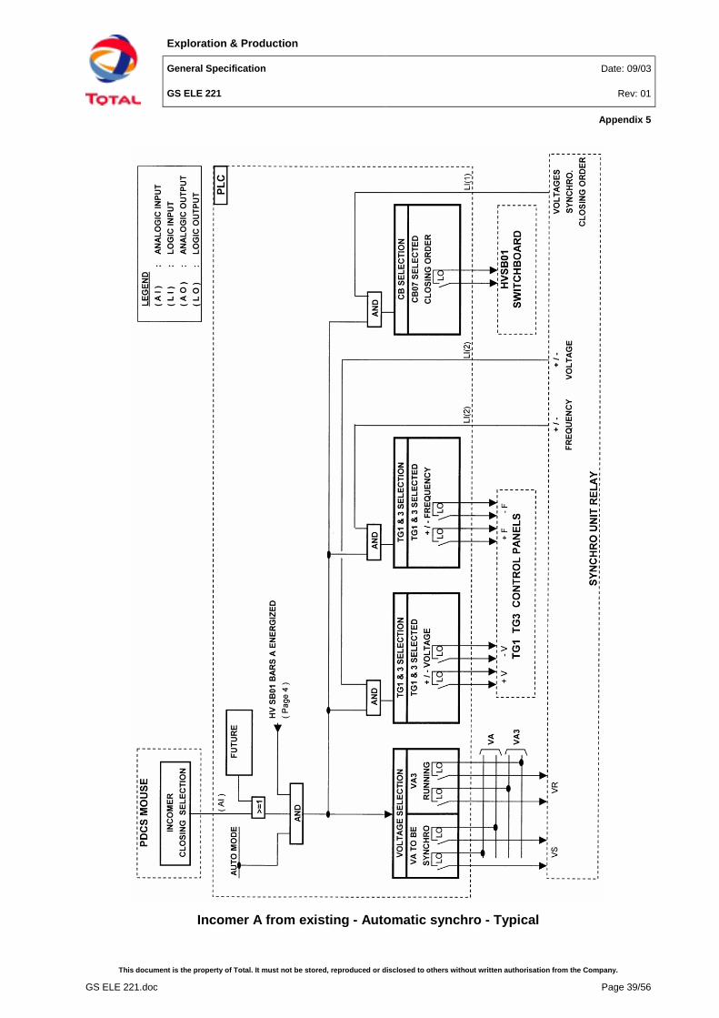
Incomer A from existing - Automatic synchro - Typical

Exploration & Production
General Specification Date: 09/03
GS ELE 221 Rev: 01
Appendix 5
This document is the property of Total. It must not be stored, reproduced or disclosed to others without written authorisation from the Company.
GS ELE 221.doc Page 40/56
Incomer B from existing - Automatic synchro - Typical

Exploration & Production
General Specification Date: 09/03
GS ELE 221 Rev: 01
Appendix 5
This document is the property of Total. It must not be stored, reproduced or disclosed to others without written authorisation from the Company.
GS ELE 221.doc Page 41/56
Diesel generator - Automatic synchro - Typical

Exploration & Production
General Specification Date: 09/03
GS ELE 221 Rev: 01
Appendix 5
This document is the property of Total. It must not be stored, reproduced or disclosed to others without written authorisation from the Company.
GS ELE 221.doc Page 42/56
Emergency switchboard CBE02 - Automatic synchro - Typical

Exploration & Production
General Specification Date: 09/03
GS ELE 221 Rev: 01
Appendix 6
This document is the property of Total. It must not be stored, reproduced or disclosed to others without written authorisation from the Company.
GS ELE 221.doc Page 43/56
Appendix 6 HV logic diagrams - Typicals
Turbogenerator incomer - Typical diagram

Exploration & Production
General Specification Date: 09/03
GS ELE 221 Rev: 01
Appendix 6
This document is the property of Total. It must not be stored, reproduced or disclosed to others without written authorisation from the Company.
GS ELE 221.doc Page 44/56
Tie circuit breaker - Typical diagram

Exploration & Production
General Specification Date: 09/03
GS ELE 221 Rev: 01
Appendix 6
This document is the property of Total. It must not be stored, reproduced or disclosed to others without written authorisation from the Company.
GS ELE 221.doc Page 45/56
Incomer/Outgoer to/from existing switchboard - Typical diagram

Exploration & Production
General Specification Date: 09/03
GS ELE 221 Rev: 01
Appendix 6
This document is the property of Total. It must not be stored, reproduced or disclosed to others without written authorisation from the Company.
GS ELE 221.doc Page 46/56
Outgoer circuit breaker - Typical diagram

Exploration & Production
General Specification Date: 09/03
GS ELE 221 Rev: 01
Appendix 7
This document is the property of Total. It must not be stored, reproduced or disclosed to others without written authorisation from the Company.
GS ELE 221.doc Page 47/56
Appendix 7 Emergency switchboard - Incomers - Logic diagrams -Typicals
Emergency diesel generator incomer - Typical diagram

Exploration & Production
General Specification Date: 09/03
GS ELE 221 Rev: 01
Appendix 7
This document is the property of Total. It must not be stored, reproduced or disclosed to others without written authorisation from the Company.
GS ELE 221.doc Page 48/56
Incomer from main LV switchboard - Typical diagram

Exploration & Production
General Specification Date: 09/03
GS ELE 221 Rev: 01
Appendix 7
This document is the property of Total. It must not be stored, reproduced or disclosed to others without written authorisation from the Company.
GS ELE 221.doc Page 49/56
Emergency diesel generator starting sequence - Typical diagram

Exploration & Production
General Specification Date: 09/03
GS ELE 221 Rev: 01
Appendix 8
This document is the property of Total. It must not be stored, reproduced or disclosed to others without written authorisation from the Company.
GS ELE 221.doc Page 50/56
Appendix 8 Main LV switchboard - Logic diagrams - Typicals
T01 transformer incomer (CB101) - Typical diagram

Exploration & Production
General Specification Date: 09/03
GS ELE 221 Rev: 01
Appendix 8
This document is the property of Total. It must not be stored, reproduced or disclosed to others without written authorisation from the Company.
GS ELE 221.doc Page 51/56
T02 transformer incomer (CB102) - Typical diagram

Exploration & Production
General Specification Date: 09/03
GS ELE 221 Rev: 01
Appendix 8
This document is the property of Total. It must not be stored, reproduced or disclosed to others without written authorisation from the Company.
GS ELE 221.doc Page 52/56
Tie (CB103) - Typical diagram

Exploration & Production
General Specification Date: 09/03
GS ELE 221 Rev: 01
Appendix 8
This document is the property of Total. It must not be stored, reproduced or disclosed to others without written authorisation from the Company.
GS ELE 221.doc Page 53/56
Outgoer to emergency (CB104) - Typical diagram

Exploration & Production
General Specification Date: 09/03
GS ELE 221 Rev: 01
Appendix 9
This document is the property of Total. It must not be stored, reproduced or disclosed to others without written authorisation from the Company.
GS ELE 221.doc Page 54/56
Appendix 9 Load shedding - Logic diagrams - Typicals
Load shedding - Typical diagram

Exploration & Production
General Specification Date: 09/03
GS ELE 221 Rev: 01
Appendix 9
This document is the property of Total. It must not be stored, reproduced or disclosed to others without written authorisation from the Company.
GS ELE 221.doc Page 55/56
Load shedding - Typical diagram

Exploration & Production
General Specification Date: 09/03
GS ELE 221 Rev: 01
Appendix 10
This document is the property of Total. It must not be stored, reproduced or disclosed to others without written authorisation from the Company.
GS ELE 221.doc Page 56/56
Appendix 10 Alternates and options
1 - AlternatesNumber Description Yes No
A 1 switchroom monitored from FEP located in ControlRoom
B 2 switchrooms or more monitored from FEP located inControl Room
C 1 switchroom monitored from FEP located in switchroom
2 - OptionsNumber Description Yes No
1 1 master Programmable Logic Controller (non redundantPLC)
2 2 master Programmable Logic Controllers (redundantPLC’s)
3 Automatic synchronization 4 Manual synchronization 5 Power calculation for load shedding initiation 6 Automatic source transfer 7 Load shedding 8 Reacceleration and restarting 9 Existing plant monitored from PDCS 10 Management and coordination with equipment supplied
by others
11 Factory tests with all switchboards, panels, etc.connected
12 Tests after erection on site