electrical drive systems 324 - synchronous...
TRANSCRIPT
Electrical Drive Systems 324Synchronous Generators
Dr. P.J Randewijk
Stellenbosch UniversityDep. of Electrical & Electronic Engineering
Stephan J. Chapman
Chapter 4 (5th Edition)
1 / 36
Outline
1 Chapter 4 – Synchronous Generator4.1 – Synchronous Generator Construction4.2 – The Speed of Rotation of a SynchronousGenerator4.3 – The Internal Generated Voltage of aSynchronous Generator4.4 – The Equivalent Circuit of a SynchronousGenerator4.5 – The Phasor Diagram of a SynchronousGenerator4.6 – Power and Torque in Synchronous Generators4.7 – Measuring Synchronous Generator ModelParameters4.8 – The Synchronous Generator Operating Alone4.9 – Parallel Operation of Synchronous Generators4.11 – Synchronous Generator Ratings
2 / 36
4.1 Construction
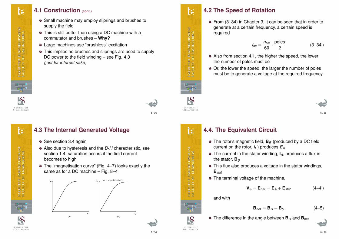
There are basically two types of synchronousgenerators
Cylindrical or non-salient pole rotor machinesfor “high speed” applicationse.g. steam turbinesUsually limited to 2 or 4 pole machines
3 / 36
4.1 Construction (cont.)
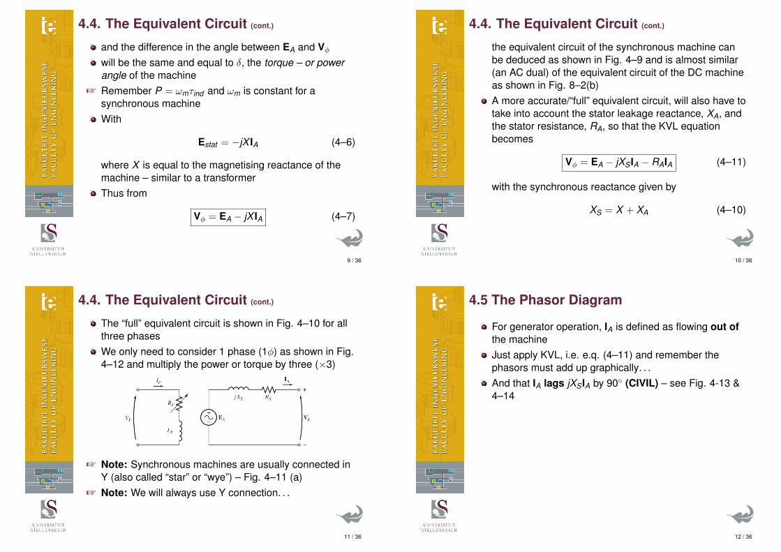
Salient pole rotor machinesfor “low speed” applications (> 4 poles)e.g. hydro-electrical turbines
4 / 36
4.1 Construction (cont.)
Small machine may employ sliprings and brushes tosupply the fieldThis is still better than using a DC machine with acommutator and brushes – Why?Large machines use “brushless” excitationThis implies no brushes and sliprings are used to supplyDC power to the field winding – see Fig. 4.3(just for interest sake)
5 / 36
4.2 The Speed of Rotation
From (3–34) in Chapter 3, it can be seen that in order togenerate at a certain frequency, a certain speed isrequired
fse =nsm
60· poles
2(3–34’)
Also from section 4.1, the higher the speed, the lowerthe number of poles must beOr, the lower the speed, the larger the number of polesmust be to generate a voltage at the required frequency
6 / 36
4.3 The Internal Generated Voltage
See section 3.4 againAlso due to hysteresis and the B-H characteristic, seesection 1.4, saturation occurs if the field currentbecomes to highThe “magnetisation curve” (Fig. 4–7) looks exactly thesame as for a DC machine – Fig. 8–4
7 / 36
4.4. The Equivalent Circuit
The rotor’s magnetic field, BR (produced by a DC fieldcurrent on the rotor, IF ) produces EA
The current in the stator winding, IA, produces a flux inthe stator, BS
This flux also produces a voltage in the stator windings,Estat
The terminal voltage of the machine,
Vφ = Enet = EA + Estat (4–4’)
and with
Bnet = BR + BS (4–5)
The difference in the angle between BR and Bnet
8 / 36
4.4. The Equivalent Circuit (cont.)
and the difference in the angle between EA and Vφwill be the same and equal to δ, the torque – or powerangle of the machine
+ Remember P = ωmτind and ωm is constant for asynchronous machineWith
Estat = −jX IA (4–6)
where X is equal to the magnetising reactance of themachine – similar to a transformerThus from
Vφ = EA − jX IA (4–7)
9 / 36
4.4. The Equivalent Circuit (cont.)
the equivalent circuit of the synchronous machine canbe deduced as shown in Fig. 4–9 and is almost similar(an AC dual) of the equivalent circuit of the DC machineas shown in Fig. 8–2(b)A more accurate/“full” equivalent circuit, will also have totake into account the stator leakage reactance, XA, andthe stator resistance, RA, so that the KVL equationbecomes
Vφ = EA − jXSIA − RAIA (4–11)
with the synchronous reactance given by
XS = X + XA (4–10)
10 / 36
4.4. The Equivalent Circuit (cont.)
The “full” equivalent circuit is shown in Fig. 4–10 for allthree phasesWe only need to consider 1 phase (1φ) as shown in Fig.4–12 and multiply the power or torque by three (×3)
+ Note: Synchronous machines are usually connected inY (also called “star” or “wye”) – Fig. 4–11 (a)
+ Note: We will always use Y connection. . .
11 / 36
4.5 The Phasor Diagram
For generator operation, IA is defined as flowing out ofthe machineJust apply KVL, i.e. e.q. (4–11) and remember thephasors must add up graphically. . .And that IA lags jXSIA by 90◦ (CIVIL) – see Fig. 4-13 &4–14
12 / 36

4.6 Power and Torque
The mechanical input power to the generator that isconverted to electrical power,
Pconv = τindωm (4–14)= 3EAIA cos γ (4–15)
Which is similar to a DC machine, with the onlydifference that:
+ this is an AC circuit, hence the angle between EA and IAneeds to be taken into account
+ there are three (3) phases that contributes to thedelivery of power & torque
If we assume that RA ≈ 0 (which is true for very largesynchronous generators)
Pconv = Pout = 3VφIA cos θ (4–17)
13 / 36
4.6 Power and Torque (cont.)
+ N.B. From Fig. 4–16,
it can be proven that:
Pconv =3VφEA
XSsin δ (4–20)
14 / 36
4.6 Power and Torque (cont.)
With δ the torque angle of power angle of the machine,i.e. the angle between Vφ and EA
This is the same angle as the angle between Bnet andBR with Vφ ≈ Enet – see eq. (4–4’)Also with P = ωmτind,
τind =3VφEA
ωmXSsin δ (4–22)
15 / 36
4.7 Measuring the Model Parameters
The open- circuit characteristic (OCC) curve, Fig.4–17(a) is the same as the magnetisation curve, Fig.4–7(b)Saturation occurs if the DC field current, IF , becomes tohighWithout saturation, EA (which is equal to Vφ becausethe machine is open-circuit, i.e. IA = 0) would havefollowed the air-gap lineFor the short-circuit characteristic (SCC) curve, therelationship between IA and IF is linear.This is due to the fact that with XA & RA � X , BR ≈ BSso that Bnet ≈ 0 and thus Enet ≈ 0 and thus the totalflux, φ ≈ 0 – see eq. (3–38)
16 / 36
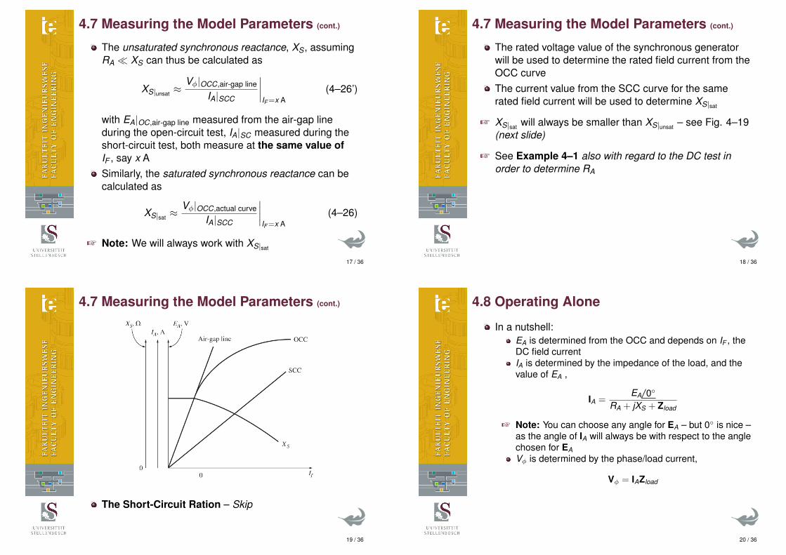
4.7 Measuring the Model Parameters (cont.)
The unsaturated synchronous reactance, XS, assumingRA � XS can thus be calculated as
XS|unsat ≈Vφ|OCC,air-gap line
IA|SCC
∣∣∣∣IF=x A
(4–26’)
with EA|OC,air-gap line measured from the air-gap lineduring the open-circuit test, IA|SC measured during theshort-circuit test, both measure at the same value ofIF , say x ASimilarly, the saturated synchronous reactance can becalculated as
XS|sat ≈Vφ|OCC,actual curve
IA|SCC
∣∣∣∣IF=x A
(4–26)
+ Note: We will always work with XS|sat
17 / 36
4.7 Measuring the Model Parameters (cont.)
The rated voltage value of the synchronous generatorwill be used to determine the rated field current from theOCC curveThe current value from the SCC curve for the samerated field current will be used to determine XS|sat
+ XS|sat will always be smaller than XS|unsat – see Fig. 4–19(next slide)
+ See Example 4–1 also with regard to the DC test inorder to determine RA
18 / 36
4.7 Measuring the Model Parameters (cont.)
The Short-Circuit Ration – Skip
19 / 36
4.8 Operating Alone
In a nutshell:EA is determined from the OCC and depends on IF , theDC field currentIA is determined by the impedance of the load, and thevalue of EA ,
IA =EA 0◦
RA + jXS + Zload
+ Note: You can choose any angle for EA – but 0◦ is nice –as the angle of IA will always be with respect to the anglechosen for EAVφ is determined by the phase/load current,
Vφ = IAZload
20 / 36
4.8 Operating Alone (cont.)
When asked to draw phasor diagram, similar to thatshown in Fig. 4–22 – which are with respect toVφ = Vφ 0◦, all the phasor are just rotated by the angleof Vφ as calculated aboveIn this section we can clearly see the effect a unity,lagging or leading power factor have on the voltageregulation of the terminal voltage
+ Note: From Fig. 4–25 we can see that with a fixedexcitation (i.e. fixed field current), the terminal voltage ofthe synchronous generator when feeding a load with aleading power factor, actually increases with an increasein line current – which is somewhat counter intuitive. . .
21 / 36
4.9 Parallel Operation
A synchronous generator needs to be synchronised withthe infinite bus before it can be connected to the infinitebusThis implies that:
the line (or phase) voltage of both must be the samethe phase sequence for both must be the samethe phase angles of both phase voltage must be thesamethe frequency of both must be the same
+ both⇐ the generator and the infinite bus
Frequency – Power and Voltage – Reactive PowerCharacteristics of a Synchronous Generator – skip –together with the speed droop (SD) characteristics andall the house diagrams
22 / 36
4.9 Parallel Operation (cont.)
The only thing that is important to remember with regardto frequency, is that if the frequency of the synchronousmachine is
slightly higher than the infinite bus – see Fig. 4–34, themachine will immediately start operating as a generatorand start delivering powerslightly lower than the infinite bus – see Fig. 4–35, themachine will immediately start operating as a motor andconsume power, not delivering power
To change the amount of real power, P, delivered to theinfinite bus, the input power from the prime mover, e.g.stream turbine needs to be changed
23 / 36
4.9 Parallel Operation (cont.)
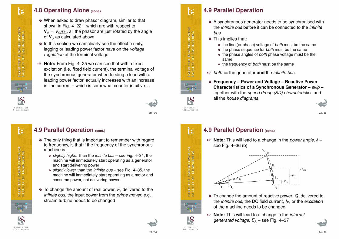
+ Note: This will lead to a change in the power angle, δ –see Fig. 4–36 (b)
To change the amount of reactive power, Q, delivered tothe infinite bus, the DC field current, IF , or the excitationof the machine needs to be changed
+ Note: This will lead to a change in the internalgenerated voltage, EA – see Fig. 4–37
24 / 36
4.9 Parallel Operation (cont.)
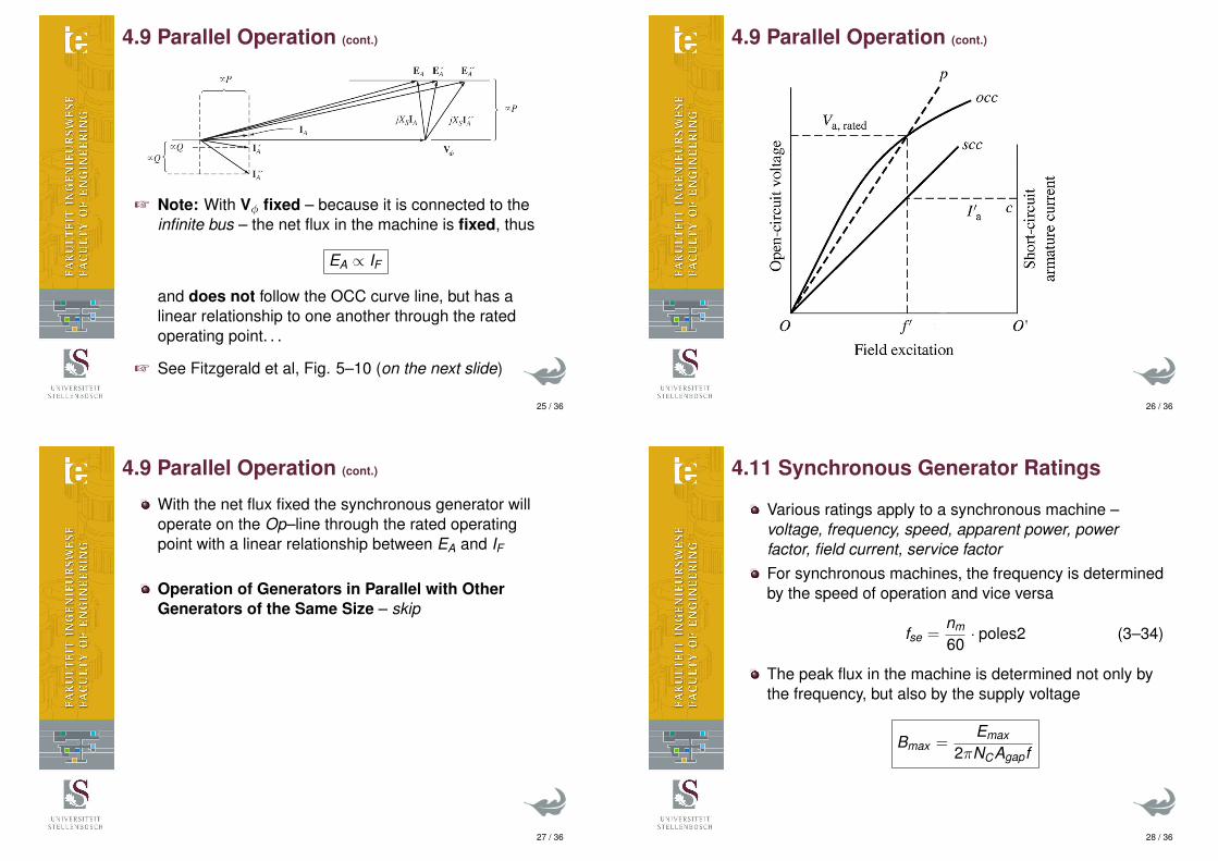
+ Note: With Vφ fixed – because it is connected to theinfinite bus – the net flux in the machine is fixed, thus
EA ∝ IF
and does not follow the OCC curve line, but has alinear relationship to one another through the ratedoperating point. . .
+ See Fitzgerald et al, Fig. 5–10 (on the next slide)
25 / 36
4.9 Parallel Operation (cont.)
26 / 36
4.9 Parallel Operation (cont.)
With the net flux fixed the synchronous generator willoperate on the Op–line through the rated operatingpoint with a linear relationship between EA and IF
Operation of Generators in Parallel with OtherGenerators of the Same Size – skip
27 / 36
4.11 Synchronous Generator Ratings
Various ratings apply to a synchronous machine –voltage, frequency, speed, apparent power, powerfactor, field current, service factorFor synchronous machines, the frequency is determinedby the speed of operation and vice versa
fse =nm
60· poles2 (3–34)
The peak flux in the machine is determined not only bythe frequency, but also by the supply voltage
Bmax =Emax
2πNCAgapf
28 / 36

4.11 Synchronous Generator Ratings (cont.)
This implies that there must be a constantvolts-per-hertz ratio and also why 480 V, 60 Hzmachines will operate at the same flux-density valuewhen connected to a 400 V, 50 Hz supply – albeit at adifferent speed. . .The maximum AC current the machine can supply islimited by the stator copper wire diameter and themaximum allowable heat (i.e. power) this windings candissipateWith the voltage of the machine set (always given as aline-to-line value), the maximum stator current isindirectly given by the apparent power rating (measuredin kVA or MVA) of the machine
Srated =√
3VL,ratedIL,rated (4–37)
29 / 36
4.11 Synchronous Generator Ratings (cont.)
+ N.B. The power loss in the stator windings isdetermined by the magnitude of the stator current, andis not influenced by the power factor
PSCL = 3I2ARA (4–38)
The maximum DC field current possible is limited by thefield copper wire diagram and the maximum heat (i.e.power) this windings can dissipate
PPCL = I2F RF (4-39)
The maximum IF directly influence the maximum EA asEA ∝ IF
30 / 36
4.11 Synchronous Generator Ratings (cont.)
The maximum value of IA and IF or more specifically EA,limits the phasor diagram as shown in Fig. 4-47
31 / 36
4.11 Synchronous Generator Ratings (cont.)
By noting that the length of the “circle” with its origin atVφ 0◦ is proportional to IA ∝ S with Vφ and XS constant
We scale the phasor diagram of Fig. 4–48 (a) by 3Vφ
Xswith its origin at Vφ 0◦, to yield a power diagram asshown in Fig. 4–48 (b)
32 / 36

4.11 Synchronous Generator Ratings (cont.)
Unfortunately the power diagram has reactive power, Q,as its x–axis and real of active power, P, a its y–axis
33 / 36
4.11 Synchronous Generator Ratings (cont.)
By swapping the x– and y–axis around, we obtain a“traditional” power triangle type diagram with theoperational limits as shown in Fig. 4–49If the prime mover’s (e.g. steam turbine) maximumoutput power is lower than that of the generator, thatlimit can be added to the generator’s capability diagramto reflex the real operational limits of the generator –see Fig. 4–50 (next slide)
Short-Time Operation and Service FactorAll electrical machines (not just synchronous machines)can operate above their rated current values for shortperiods of timeThe time the current can be above the rated currentvalue depends on the thermal capacity or thermal timeconstant of the machine
34 / 36
4.11 Synchronous Generator Ratings (cont.)
35 / 36
4.11 Synchronous Generator Ratings (cont.)
The service factor of a machine indicates at what levelthe machine can operate indefinitely
Per-Unit System Revisited – see also 2.6 & 2.10
S3φ,base = S3φ,rated
S1φ,base =S3φ,base
3
V1φ,base =VL,rated√
3
I1φ,base =S1φ,base
V1φ,base
Zbase =V1φ,base
I1φ,base
36 / 36