electrical and ducting specifications - vent-a-hood vah spec catalog.pdf · wall cutout for...
TRANSCRIPT

Electrical and Ducting Specifications
18420_Ventahood_Spec_Ctlg 9/11/08 5:47 PM Page 1
Wall Cutout for Horizontal DuctingViewed from Front
Top of Liner
5"
5 1⁄8" 7"
CL
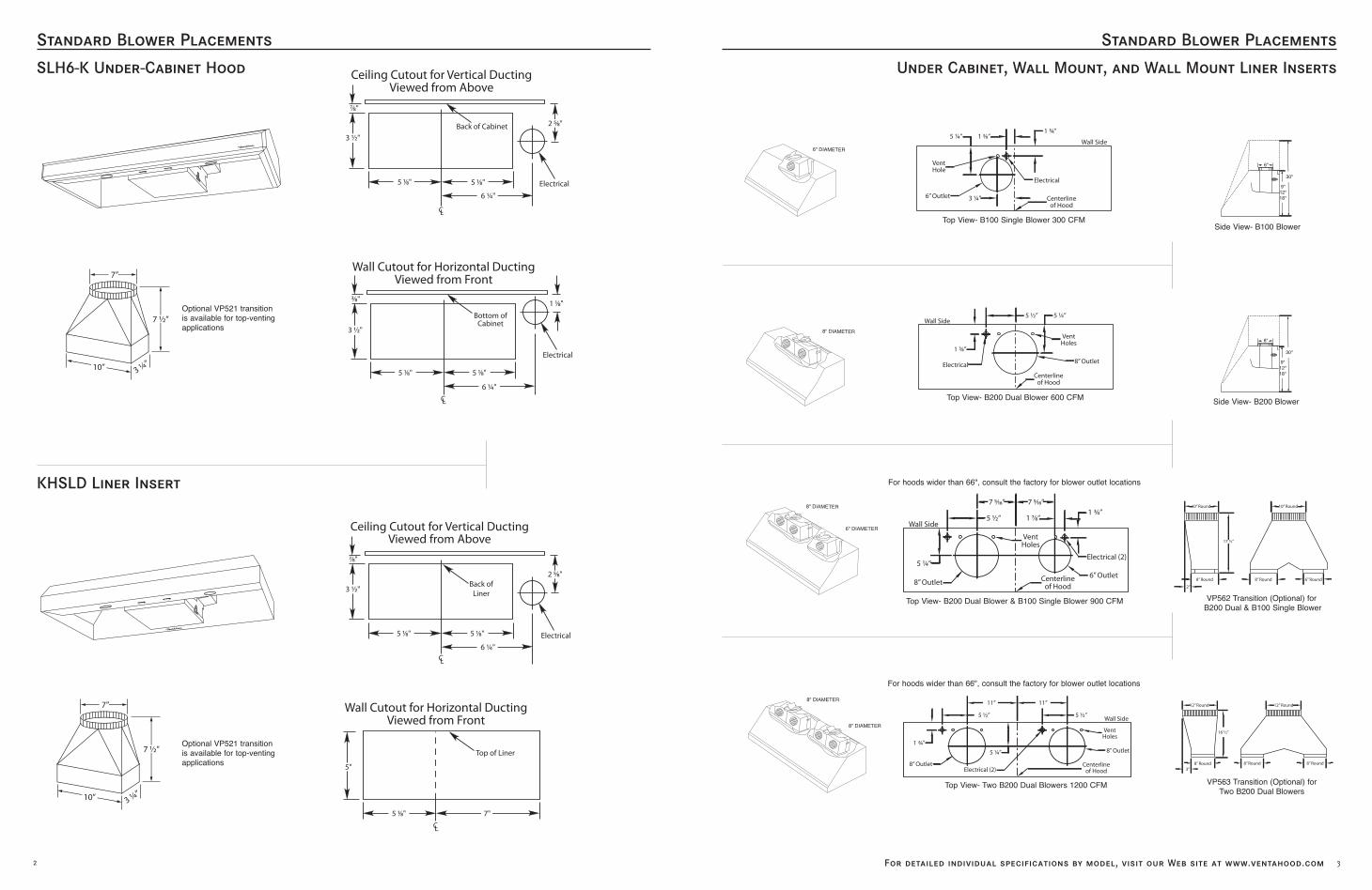
Standard Blower PlacementsStandard Blower Placements
3
SLH6-K Under-Cabinet Hood
2 For detailed individual specifications by model, visit our Web site at www.ventahood.com
Under Cabinet, Wall Mount, and Wall Mount Liner Inserts
6” Outlet
VentHole
3 ¼”
Electrical
Centerlineof Hood
Wall Side
1 ¾”1 3⁄8”5 ¼”
Electrical
1 ¾”
Centerlineof Hood
8” Outlet
VentHoles
5 ¼”5 ½”Wall Side
6"
9"12"18"
30"
8"
9"12"18"
30"
Side View- B100 BlowerTop View- B100 Single Blower 300 CFM
Side View- B200 BlowerTop View- B200 Dual Blower 600 CFM
8” Outlet6” Outlet
5 ¼”
Wall Side
VentHoles
Centerlineof Hood
Electrical (2)
5 ½”
7 5⁄16”
1 7⁄8”
7 5⁄16”
1 ¾”
11” 11”
5 ½” 5 ½”Wall Side
5 ¼”
1 ¾”
Electrical (2)8” Outlet
VentHoles
8” Outlet
Centerlineof Hood
Top View- B200 Dual Blower & B100 Single Blower 900 CFM
For hoods wider than 66", consult the factory for blower outlet locations
For hoods wider than 66", consult the factory for blower outlet locations
Top View- Two B200 Dual Blowers 1200 CFM
Wall Cutout for Horizontal DuctingViewed from Front
Bottom of Cabinet
3⁄8"
3 ½"
5 1⁄8" 5 1⁄8"
6 ¼"
1 1⁄8"
Electrical
CL
Ceiling Cutout for Vertical DuctingViewed from Above
Back of Cabinet
Electrical
7⁄8"
3 ½"
5 1⁄8" 5 1⁄8"
6 ¼"
2 5⁄8"
CL
7”
7 ½”
3 ¼”10”
Optional VP521 transition is available for top-ventingapplications
KHSLD Liner Insert
7”
7 ½”
3 ¼”10”
Optional VP521 transition is available for top-ventingapplications
6" DIAMETER
8" DIAMETER
6" DIAMETER
8" DIAMETER
8" DIAMETER
8" DIAMETER
Wall Cutout for Vertical DuctingViewed from Above
Back of
Liner
5 1⁄8"
CL
5 1⁄8"
6 ¼"
Electrical
3 ½"
7⁄8"
2 5⁄8"
10” Round 10” Round
8” Round
17 ½”
2”
8” Round 6” Round
12” Round 12” Round
16 ½”
8” Round 8” Round8” Round
3”
VP562 Transition (Optional) forB200 Dual & B100 Single Blower
VP563 Transition (Optional) for Two B200 Dual Blowers
Ceiling Cutout for Vertical DuctingViewed from Above
18420_Ventahood_Spec_Ctlg 9/11/08 5:48 PM Page 2

Standard Blower PlacementsStandard Blower Placements
54 For detailed individual specifications by model, visit our Web site at www.ventahood.com
Contemporary Wall Mount Hoods
Centerlineof Hood
Electrical
3 ¼" x 10"Outlet
1"
4 ¼"Outlet
6"
7⁄8”
WoodMounting
Strip
CutoutArea
10 ¼”
3 ½”
CL
BlowerExhaustOutlets
8” Round 6” Round
14 3⁄8”
9”
6" OutletCenterlineOf Hood
VentHoles
8" Outlet
Wall Side
Electrical (2)5 ¼"
4 ½"
6 7⁄16" 8 3⁄16"
1 7⁄8"1 ¾"
BlowerExhaustOutlet
8” Round
9”
14 3⁄8”
Wall Side
5 ¼”
Electrical
VentHoles
8” Outlet
Centerlineof Hood
5 ¼”4 ½”1 ¾”
K250 Ceiling Cutout For Vertical Ducting Viewed From Above
Top View- B200 Dual Blower 600 CFM
Wall Cutout For Horizontal Ducting Viewed From Front
(Requires VP559 Back Vent Elbow, Sold Separately)
Front View
Front View- B200 Dual Blower
Front View- B200 Dual & Single Blower
GTH
ZTH
Euro-Style Wall Mount Hoods
BlowerExhaustOutlet
5"
14"
6" Round
Top View- B100 Single Blower 300 CFM
Top View- B200 Dual Blower 600 CFM
Front View- B100 Single Blower
18"
Blower ExhaustOutlet
9"8" Round
18"
10"
8 ½”
Wall Side
7"
Electrical (2)
CenterlineOf Hood
12" OutletCentered OnTop Of Hood
1 ¾”
16 ½” 5 ½”
1 ¾”
18"
12"
7 ½"
CenterlineOf Hood
Wall Side
Electrical (2)
10" OutletCentered On
Hood Top
12 7⁄8” 9 1⁄8”
1 ¾”
14"
BlowerExhaustOutlet
5"8" Round
Front View- B200 Dual Blower
Front View- B200 Dual Blower
Front View- VP562 StandardTransition (Included)
Front View- VP563 StandardTransition (Included)
Top View- B200 Dual Blower & B100 Single Blower 900 CFM
Top View- Two B200 Dual Blowers 1200 CFM
CenterlineOf Hood
Electrical
6" Outlet
Wall Side
VentHole
1 7⁄8”1 ¾”
5 ¼”
Electrical
1 ¾”
Centerlineof Hood
8” Outlet
VentHoles
5 ¼”5 ½”Wall Side
6" DIAMETER
8" DIAMETER
10" DIAMETER
12" DIAMETER
Top View- B200 Dual Blower & B100 Single Blower 900 CFM
Optional VP521 transitionis available for top-ventingapplications
Optional Duct Cover
10” Round 10” Round
8” Round
17 ½”
2”
8” Round 6” Round
Optional Duct Cover
Optional Duct Cover
Optional Duct Cover
Optional Duct Cover
Optional VP559 back vent elbow isavailable for back vent applications
Optional Duct Cover
Optional Duct Cover
VP562 Transition (Optional) for B200Dual & B100 Single Blower
Ceiling Cutout for Vertical DuctingViewed from Above
7”
7 ½”
3 ¼”10”
18420_Ventahood_Spec_Ctlg 9/11/08 5:48 PM Page 4

Standard Blower PlacementsStandard Blower Placements
76 For detailed individual specifications by model, visit our Web site at www.ventahood.com
12" and 18" Island Hoods and Liner Inserts
12" Tall Liner In
18"
9"
CenterlineOf Hood
8" TransitionOpening (2)
9" Above TopOf Hood
Electrical (2)
Vent Holes
CenterlineOf Hood
5" x 16"Exhaust
Opening (2)
11" 11"
2 1⁄8”¾”
8” TransitionOpening 9”Above Top
of Hood
5” x 16”ExhaustOpening
Centerlineof Hood
Vent Holes
Electrical
Centerlineof Hood ¾”
2 1⁄8”
12" Round 12" Round
11 ¼"
8" Round 8" Round 8" Round
12"
11 1/4"
9"
16"5"
8" Round 8" Round
12"
9"
12"
9"
Top View- T200 Dual Blower 550 CFM
VP565 Standard Transition (Included)
Top View- Two T200 Dual Blowers 1100 CFM
On selected models, hoods wider than 66"may be ordered with additional halogen
lighting between the blowers
Top View- T400 Cluster Blower 1100 CFM
VP564 Standard Transition (Included)
Side View-Transition Installed
Side View-Transition Installed
Side View-Transition Installed
Contemporary Wall Mount Hoods
Centerlineof Hood
VentHole
6” Outlet1 ½”
Electrical
Wall Side
1 ¾”
½”5 ¼”
Top View- B100 Single Blower 300 CFM
CWLH9
10” Round 10” Round
8” Round
17 ½”
2”
8” Round 6” Round
12” Round 12” Round
16 ½”
8” Round 8” Round8” Round
3”
VP562 Transition (Optional) forB200 Dual & B100 Single Blower
VP563 Transition (Optional) for Two B200 Dual Blowers
XLH12 with optional roundduct collars and finishedround duct
Wall Side
1 ¾”4 ½” 5 ¼”
5 ¼” Vent Holes
Centerlineof Hood
8”Outlet
6" Outlet8" Outlet
5 ¼”
Wall Side
7 1⁄16”
5 ½”
7 9⁄16”
1 7⁄8”1 ¾”
VentHoles
Centerlineof Hood
Electrical (2)
11”
5 ½”
11”
5 ½”Wall Side
1 ¾”
8" Outlet
5 ¼”
Electrical (2)
VentHoles
8" Outlet
Centerlineof Hood
18"
9"
Side View-Transition Installed
12"
9"
Side View-Transition Installed
Wall Side
5 ¼”
Electrical
Vent Holes
8” Outlet
Centerlineof Hood
5 ¼”4 ½”1 ¾”
BlowerExhaustOutlet
12"
3"
8" Round
CutoutArea 9”
3⁄8”
6 ½”
WoodMounting
Strip
CL
Top View- B200 Dual Blower 600 CFM
Top View- B200 Dual Blower & B100 Single Blower 900 CFM
Top View- Two B200 Dual Blowers 1200 CFM
XLH12 with optional10" x 10" duct cover
XLH12 with optional squareduct collars and finishedround duct
Top View- B200 Dual Blower 600 CFM
Side View-Transition Installed
9"
16"5"
8" Round 8" Round
Two VP565 Standard Transitions (Included)
12" Transition Opening 11 ¼"
Above Topof Hood
1 ¾"
8” BlowerOutlets
Vent Holes
5 ½"
10 ½"
Centerlineof Hood
Centerlineof Hood
Electrical (2)
Front View- B200 Dual Blower
Optional Duct Cover
Optional Duct Cover
Wall Cutout For Horizontal Ducting Viewed From Front
(Requires VP561 Back Vent Elbow, Sold Separately)
18420_Ventahood_Spec_Ctlg 9/11/08 5:48 PM Page 6

Standard Blower Placements
9For detailed individual specifications by model, visit our Web site at www.ventahood.com
Standard Blower Placements
30" Tall Island Hoods
8
Euro-Style Island Hoods
12" Round 12" Round
11 ¼"
8" Round 8" Round 8" Round
2 ¼”
18”
12" TransitionOpening 2 ¼”Above Top of
Hood
8” BlowerOutlets Centerline
of Hood
Centerlineof Hood
Vent Holes
Electrical (2)
7 ¾”
10 ½”
VP564 Standard Transition (Included)
Top View- T400 Cluster Blower 1100 CFM
Side View-Transition Installed
9"
16"5"
8" Round 8" Round
CenterlineOf Hood
5" x 16"ExhaustOpening
8" TransitionOpening 3” Below Top
of Hood
CenterlineOf Hood
Vent Holes
Electrical7 ¾"
Top View- T200 Dual Blower 550 CFM
T200 Dual Blower Includes One VP565 Standard Transition.
Two T200 Dual Blowers Includes Two VP565 Standard Transitions
30"
30"
Centerlineof Hood
Centerlineof Hood
Vent Holes
Electrical (2)
11” 11”
7 ¼”
8” TransitionOpening (2)3” Below Top
of Hood
5” x 16”Exhaust
Opening (s)
30"
3"
9"
16"5"
8" Round 8" Round
18"
CenterlineOf Hood
5" x 16"ExhaustOpening
8" TransitionOpening
CenterlineOf Hood
Vent Holes
Electrical7 ¾"
Top View- T200 Dual Blower 550 CFM
VP565 Standard Transition (Included)
Side View-Transition Installed
Quiet. Turn on a Vent-A-Hood® range hood, and you’ll hear only a whisper of air movement, because the Magic Lung® blower system provides the quietest ventilation available. Unbiased tests show that the Magic Lung® blower has one of the lowest sound ratings in the industry – especially at high speed –where it counts.
Efficient.The powerful Magic Lung® blower traps cooking contaminants, liquifies grease vapor and removes heat polluted air. It combines sufficient air pressureand constant speed centrifugal filtration – and because it doesn’t pull air through a filter – it provides the most efficient kitchen ventilation availabletoday. This filtration system, along with the open canopy design of a Vent-A-Hood®, delivers performance farmore efficiently than other filtration systems.
Easy-cleaning.The Magic Lung® blower housing snaps apart for easy cleaning in the dishwasher or with warm soapy water. TheMagic Lung® motor is also enclosed in a specially designed housing to keep it out of the grease flow, therebymaximizing its operational performance. Easy to snap-apart housings and fully enclosed motors mean no hiddengrease in hard to reach areas behind a mesh or baffle filter as with other brands in the marketplace.
Fire-safety.The Magic Lung® constant speed centrifugal blower is designed to liquefy grease in the sealed blower housingand to create a pressure barrier, lowering the risk of an attic or wall fire. In 70+ years of manufacturing thissystem, Vent-A-Hood® has never received a report of an attic or wall fire when the Magic Lung® has been in use.
Powerful.Magic Lung® blowers can be configured to provide the power you need for even the most demanding cooking surface.Each highly efficient Magic Lung® blower supplies 300 CFM of air movement; you can combine multiple blowers in a single Vent-A-Hood® range hood tocreate the perfect ventilation for your cooking surface.
What makes a Vent-A-Hood® a Vent-A-Hood®?
Top View- Two T200 Dual Blowers 1100 CFM
Side View-Transition Installed
Optional Duct Cover
Optional Duct Cover
18420_Ventahood_Spec_Ctlg 9/11/08 5:48 PM Page 8

Standard Blower Placements
11
Contemporary Island Hoods
10 For detailed individual specifications by model, visit our Web site at www.ventahood.com
Electrical and Ducting Specifications
Ducting Do’s and Don’tsNNEEVVEERR restrict the duct size. When combining ducts together, the square inch area must reflect the totalsquare inch area of the ducts being combined. Using Vent-A-Hood transitions (where applicable) will ensureproper efficiency.
Blower Duct Size Sq. Inch Area Vent-A-Hood Transition
K250 3 1/4" x 10" or equivalent 32.5" N/ASingle (B100) 6" round or equivalent 28" N/ADual (B200) 8" round or equivalent 50" N/ADual (T200) 8" round or equivalent 50" VP565 (Included)Dual and Single (B200 & B100) 10" round or equivalent 79" VP562 (Optional)Two Dual (Two B200s) 12" round or equivalent 113" VP563 (Optional)Cluster (T400) 12" round or equivalent 113" VP564 (Included)
Do not use flexible or corrugated duct. This type of duct will restrict airflow and reduce performance. Onlyuse smooth, galvanized, metal duct. Observe local codes regarding special duct requirements and placement of duct against combustibles. Make the duct run as short and as straight as possible with as few turns as possible. Avoid sharp-angled turns. Instead, use smooth, gradual turns such as adjustable elbows or 45 degreeangled turns. For duct runs over 20 feet, increase the duct diameter by one inch for every ten feet of duct. A 90degree elbow is equal to 5 feet of duct. Using Vent-A-Hood roof jacks or wall louvers will ensure proper efficiency. Airflow must not be restricted at the end of the duct run. Do not use screen wire or spring-loadeddoors on wall louvers or roof jacks. Do not terminate venting into an attic or chimney. Where possible, sealjoints with duct tape. The hood must be ducted to the outdoors without restrictions.
9"
9"
Centerlineof Hood
Electrical
6 ¼”
Vent Holes
8” TransitionOpening 7”Above Top
of Hood
5” x 16”ExhaustOpening
Centerlineof Hood
9 ¼"
23 ¼"
Centerlineof Hood
8” BlowerOutlets Centerline
of Hood
Electrical
6 ¼”
10 ½”
Vent Holes
12” TransitionOpening 9 ¼”
Above Topof Hood
Top View- T200 Dual Blower 550 CFM
Top View- T400 Cluster Blower 1100 CFM
Side View-Transition Installed
Side View-Transition Installed
CILH9
CILH9
IZTH
IZTH
7"
21"
Side View-Transition Installed
9"
16"5"
8" Round 8" Round
VP565 Standard Transition (Included)
12" Round 12" Round
11 ¼"
8" Round 8" Round 8" Round
Centerlineof Hood
Centerlineof Hood
Electrical
Vent Holes
¾”2 1⁄8”
5” x 16”Exhaust Opening
8” TransitionOpening 9”Above Top
of Hood
11” 11”
Centerlineof Hood
Electrical (2)
Vent Holes2 1⁄8”
Centerlineof Hood
¾”
5” x 16”Exhaust
Opening (2)
8” TransitionOpening (2)
9” Above Topof Hood
YES NO
9"
16"5"
8" Round 8" Round
VP565 Standard Transition (Included)
9"
9"
Side View-Transition Installed
9"
16"5"
8" Round 8" Round
Two VP565 Standard Transitions (Included)
Top View- T200 Dual Blower 550 CFM
Top View- Two T200 Dual Blowers 1100 CFM
VP564 Standard Transition (Included)
Model Volts Amps* RPM [email protected]"†
EquivalentCFM‡
Minimum RoundDuct Size
Sones§
B100 115 1.5 1550 300 450 273 245 225 6"( 28 in2 ) 5.4
B200 115 2.9 1550 600 900 531 480 430 8"( 50 in2 ) 6.5
B200 Dual & B100 Single 115 4.4 1550 900 1350 804 725 655 10"( 79 in2 ) 6.3
Two B200 Duals 115 5.8 1550 1200 1800 1062 960 860 12"( 113 in2 ) 6.6
K250 (Top Vent) 115 2.2 1550 250 375 223 220 190 7"( 38 in2 ) 7.4
K250 (Back Vent) 115 2.2 1550 220 330 215 195 180 7"( 38 in2 ) 7.4
T200 Dual 115 2.9 1550 550 900 507 471 431 8"( 50 in2 ) 6.0
T400 Cluster 115 5.8 1550 1100 1800 998 855 774 12"( 113 in2 ) 6.4
RM1000 Remote 115 3.2 1100 945 N/A 922 884 852 10"( 79 in2 ) N/A
RM1500 Remote 115 5.0 1130 1500 N/A 1455 1410 1375 10"( 79 in2 ) N/A
Optional Duct Cover
Optional Duct Covers
Optional Duct Cover
Optional Duct Cover
Add 2.5 amps for each warming lamp and 0.5 additional amp for each halogen light bulb. In general, there will be one halogen light for every 14" of hood width, evenly spaced along the light box. Island hoods will have four halogen lights, one in each corner. Model GTH has two halogen lights,one on each side. Model ZTH has four halogen lights, two on each side. Hoods equipped with fluorescent lighting will have one light fixture per blower unit except for island hoods, which have two (on the front and back of the hood).CFM rating is based on 0.0 inches static pressure (resistance in the ducting, turns, roof caps, etc.) CFM rating will change as static pressure isincreased. Static pressure increases because of ducting and length of duct run.Equivalent CFM refers to the fact that the Magic Lung® uses centrifugal filtration units, whereas others use conventional filters. Apply this guideline when comparing blower units made by other manufacturers.Ratings in accordance with the Standard Test Code by the Energy Systems Laboratory of the Texas Engineering Experiment Station. All tests weremeasured at full speed to demonstrate the most accurate sound rating (other manufacturers may use lower speeds for testing which don't reflectaccurate operating sound levels).
*
†
‡
§
18420_Ventahood_Spec_Ctlg 9/11/08 5:48 PM Page 10

P.O. Box 830426
1000 N. Greenville Ave.
Richardson, TX 75083-0426
800-331-2492
www.ventahood.com
18420_Ventahood_Spec_Ctlg 9/11/08 5:48 PM Page 12