electric-service-standards florida power light fpl.pdf
TRANSCRIPT

8/18/2019 electric-service-standards Florida Power Light FPL.pdf
http://slidepdf.com/reader/full/electric-service-standards-florida-power-light-fplpdf 1/118
Electric Service Standardsfor Overhead, Underground andResidential Subdivision Areas
201
Online EditionDistribution Construction Processes
SECTION
Foreword
Summary of 20 Revisions Table of Contents
I. Definitions
II. General
III. Service Provisions IV. Service and Meter Connections
V. Requirements for Transformers Situated on Customer PropertyVI. Metering Equipment
VII. Approved Metering Equipment Enclosure List
VIII. Grounding
IX. Motors, Controllers and Air Conditioners
X. Electrical Disturbances
XI. Radio, Television and Miscellaneous Antennas
XII. Street and Outdoor Security Lighting
XIII. Safety
© 2009, Florida Power & Light Company

8/18/2019 electric-service-standards Florida Power Light FPL.pdf
http://slidepdf.com/reader/full/electric-service-standards-florida-power-light-fplpdf 2/118
JUST A REMINDER!
FLORIDA STATUTE 812.14 STATES "IT IS UNLAWFUL TO WILLFULLY ALTER, TAMPERWITH, INJURE, OR KNOWINGLY SUFFER TO BE INJURED ANY METER, METER SEAL,PIPE CONDUIT, WIRE, LINE, CABLE, TRANSFORMER... OR TO ALTER THE INDEX ORBREAK THE SEAL OF ANY METER..."
PLEASE KEEP SAFETY FIRST – CALL YOUR LOCAL FPL CONSTRUCTION OFFICE FOR AN
APPOINTMENT TO DISCONNECT THE SERVICE AND REMOVE THE SEAL/METER. REFERTO SECTION III-I OF THESE ELECTRIC SERVICE STANDARDS REGARDING THEEXCEPTION ALLOWED BY FPL.
FOREWORD
FPL, in cooperation with customers and their agents, wishes to provide adequate electric service in an
expeditious manner.
This publication, FPL's Electric Service Standards (ESS), is intended to furnish information often required by
customers and their agents (builders, architects, engineers, electricians, etc.) to receive FPL's electric
service. The ESS is subject to and subordinate in all respects to FPL's Tariff, as amended from time to time
and approved by the Florida Public Service Commission, the Florida Administrative Code as it pertains to
publicly held utilities, and to the provisions of the current edition of the National Electrical Safety Code.
This document is not intended to be all inclusive and is not a substitute for direct communicationbetween the Customer and FPL. This direct communication is essential to mutually understanding
service needs and requirements, and the ability of FPL to provide prompt and adequate electric
service.
The personal pronouns "he", "him", "his", etc., when used in the text, are generic and not intended to specify
a particular gender.
FPL's ESS is revised periodically due to ongoing changes in engineering and construction practices.
Consequently, some of the provisions contained herein may be obsolete. It is essential that the Customer
or his agent contact FPL's representative to ensure he has the latest issue of FPL's Electric Service
Standards, in addition to any new or other pertinent information that may not be published. The
latest version and other information can be found by visiting us on the web at www.FPL.com/builder .
CHANGE OF MAILING ADDRESS
To all those builders, developers, architects, engineers, electrical contractors, electrical inspectors, etc. on
FPL's current mailing list, FPL will distribute this publication as it becomes revised in the future. Should you
desire a copy of either this or future issues, or wish to notify FPL regarding a change of mailing address,
please mail your request to:
FPL
ESS Administrator (DO3/JW)
P.O. Box 14000
Juno Beach, FL 33408-0420
And, please provide the following information:
EXISTING ADDRESS INFORMATION NEW or REVISED ADDRESS INFORMATION
(If already on list)
Name: Name:
Attention: (if applicable): Attention: (if applicable):
Street Address or P.O. Box: Street Address or P.O. Box:
City, State, and Zip: City, State, and Zip:
Phone Number: Phone Number:

8/18/2019 electric-service-standards Florida Power Light FPL.pdf
http://slidepdf.com/reader/full/electric-service-standards-florida-power-light-fplpdf 3/118
Electric Service Standards
DATE
10-09-14
PREPARED BY SUBJECT
SUMMARY OF 2013 EDITION REVISIONS
SECTION: PAGE
Delivery Assurance –Design Support
REV: 1 of 1
© 2013, Florida Power & Light Company Page 1 of 1
Section Title Revision Date
VII Approved Meter Enclosures Revised, updated the approved enclosure list Aug 2013
IV Service Provisions Revised, conductor installation must comply with NEC Article 300.3 Feb 2014
Fig IV-12b
Service Provisions – Multiple MeterCenters
Revised, request to mark the inside of meter enclosures withaddress served when possible to do so, , clarified that paint or otherdurable marking is required (removed reference to “tag”) Oct 2014
VI.EMetering Equipment – Identificationof Meters
Revised, request to mark the inside of meter enclosures withaddress served when possible to do so Oct 2014
Fig IV-13a
Service Provisions – Service toMobile Home Revised, added table of acceptable pole classes Oct 2014

8/18/2019 electric-service-standards Florida Power Light FPL.pdf
http://slidepdf.com/reader/full/electric-service-standards-florida-power-light-fplpdf 4/118
Electric Service Standards
DATE
06-10-13
PREPARED BY SUBJECT
TABLE OF CONTENTS
SECTION: PAGE
Delivery Assurance –Design Support
TOC: 1 of 3
© 2013, Florida Power & Light Company Page 1 of 3
I. DEFINITIONS ........................................................................................................................................................... 1
II. GENERAL ................................................................................................................................................................. 1
A. Early Notification and Coordination .......................................................................................................... 1B. Application for Electric Service .................................................................................................................. 1C. Availability of Desired Type of Electric Service ......................................................................................... 2D. Contributions by Customer ........................................................................................................................ 2E. Rights of Way and Easements ................................................................................................................. 2F. Measuring (Metering) Electric Consumption ............................................................................................. 3G. Conjunctive Billing or Totalized Metering as disallowed in FAC 25-6.102 ................................................ 5H. Electrical Inspections and Connection of Service ..................................................................................... 5I. Customer Responsibility for Safety and Adequacy of Wiring .................................................................... 5J. Access to FPL Facilities ............................................................................................................................. 6K. Load Balance ............................................................................................................................................. 6L. Customer Owned Generators .................................................................................................................... 6
1. Standby Generator ......................................................................................................................... 6
2. Parallel Generation and Cogeneration ........................................................................................... 6Caution ................................................................................................................................................. 7M. Unauthorized Attachments ........................................................................................................................ 7N. Continuity of Service .................................................................................................................................. 7O. Conservation Programs ............................................................................................................................. 7P. Contacting FPL ......................................................................................................................................... 7
III. SERVICE PROVISIONS ........................................................................................................................................... 1
A. Standard Service ........................................................................................................................................ 1B. Point of Delivery ......................................................................................................................................... 2C. Extension of FPL's Electric Facilities ......................................................................................................... 2
1. General ........................................................................................................................................... 22. Overhead Extensions ..................................................................................................................... 23. Underground Extensions ................................................................................................................ 2
D. Residential Service (under 600v) ............................................................................................................... 3
1. Underground Service for New Residential Subdivisions (Less than 5 units per building) ............ 32. Underground Service from an Overhead System to New Residential Buildings
(Less than 5 units per building) ...................................................................................................... 43. Replacement of Existing Overhead and Underground Residential Service Laterals .................... 44. Mobile Home and Recreational Vehicle (RV) Parks ...................................................................... 45. Multiple Occupancy Buildings (5 Units or more per building) ........................................................ 56. High-Rise Residential Buildings ..................................................................................................... 6
E. Commercial Service (under 600v) ............................................................................................................. 6Commercial Underground Service ....................................................................................................... 6
a. Underground Service to Small Commercial Loads .................................................................. 7b. Underground Service to Moderate Commercial Loads ............................................................ 7c. Underground Service to Large Commercial Loads .................................................................. 7d. Automatic Throwover Facilities to Large Commercial Loads ................................................... 8e. Loop Service to Large Commercial Loads ............................................................................... 8
F. Underground Service Connections in the City of Miami Network Area .................................................... 8G. Temporary/Construction Service ............................................................................................................... 9
1. General ........................................................................................................................................... 92. Reduced Cost Alternatives ........................................................................................................... 10
a. TOP .................................................................................................................................... 10b. TUG .................................................................................................................................... 10
H. Unauthorized Connections & Disconnections .......................................................................................... 10I. Change in Service Requirements (Service Changes) ............................................................................ 10J. Service to Special Equipment ................................................................................................................... 11K. Service to Boat Facilities ............................................................................................................................ 11L. 2 Wire, 480V Metered Service ..................................................................................................................... 12
8/18/2019 electric-service-standards Florida Power Light FPL.pdf
http://slidepdf.com/reader/full/electric-service-standards-florida-power-light-fplpdf 5/118
Electric Service Standards
DATE
06-10-13
PREPARED BY SUBJECT
TABLE OF CONTENTS
SECTION: PAGE
Delivery Assurance –Design Support
TOC: 2 of 3
© 2013, Florida Power & Light Company Page 2 of 3
IV. SERVICE and METER CONNECTIONS ................................................................................................................. 1
A. Service Equipment ..................................................................................................................................... 1 1. General ........................................................................................................................................... 12. Ampere Rating ................................................................................................................................ 2
a. Residential ........................................................................................................................... 2b. Commercial .......................................................................................................................... 2c. Service Equipment Rated Below 600 Volts ........................................................................ 3d. Service Equipment Rated Over 600 Volts .......................................................................... 3
B. Overhead Service ...................................................................................................................................... 41. Vertical Clearance to Ground ......................................................................................................... 42. Clearance from Building Openings ................................................................................................. 43. Clearance from Swimming Pools ................................................................................................... 44. Anchorage for Overhead Service Drop Cable or Wires ................................................................. 55. Installation of Service Entrance ...................................................................................................... 5
C. Illustrations ................................................................................................................................................. 5Temporary/Construction Service - from Overhead System (typical) ................................................... 6Temporary/Construction Service - from Underground System (typical) ............................................. 7
FPL Electric Service and Meter Socket Requirements Form .............................................................. 8Guide for Locating Point of Delivery on Outside of Building ................................................................ 9Overhead Service - Minimum Vertical Clearances ............................................................................ 10
Attachment of Service Drop at Buildings - to the Pipe Mast ............................................................... 11 Attachment of Service Drop at Buildings - to the Structure ................................................................ 12 Attachment of Service Drop at Buildings - to the Wood Eave ............................................................ 13Outdoor Meter Installation - 1ph 120/240v 3 wire Overhead Service ................................................ 14Self Contained Meter Installation - Overhead Service ........................................................................ 15Lug-Type Meter Socket Installations ................................................................................................... 16Configurations for Installing (2) Mains with FPL Underground Service .............................................. 16Intersystem Bonding Termination ......................................................................................................... 17URD System Layout – Typical ............................................................................................................ 18 FPL Buried Service Lateral – Meter Socket & Down Pipe Requirements .......................................... 19Residential Multiple Occupancy Buildings - Multiple Meter Center .................................................... 20Remote Meter Location, Typically used for Service to a Mobile Home .............................................. 21
Pedestal Service - Customer Provided Meter Pedestal (typical) ........................................................ 22Mobile Home Service - "Grouped" Service to Mobile Homes ............................................................ 23Identification of Customer Cables (tagging) .......................................................................................... 24
V. REQUIREMENTS FOR TRANSFORMERS SITUATED ON CUSTOMER PROPERTY ....................................... 1 A. Padmounted Transformer Requirements .................................................................................................. 1
Protective Barriers and Planting Clearances ........................................................................................... 3B. Vault Requirements ................................................................................................................................... 4C. "Stacked Vault" Requirements ................................................................................................................... 6
VI. METERING EQUIPMENT ......................................................................................................................................... 1 A. Equipment Furnished and Installed by FPL .............................................................................................. 1B. Equipment Furnished, Installed, and Owned by the Customer ................................................................ 1C. Metering Configurations & Approved Equipment ...................................................................................... 2D. Location of Metering Equipment ................................................................................................................ 2
1. Sequence in Service Entrance ....................................................................................................... 22. Located Outdoors ........................................................................................................................... 23. Located Indoors .............................................................................................................................. 24. Flood Elevation Standards ............................................................................................................. 3
E. Identification of Meters ............................................................................................................................... 3F. Relocation or Upgrade of Metering Equipment ......................................................................................... 3G. Load Profile Metering Requirements ......................................................................................................... 3H. Installation of CTs in Customer Switchgear ................................................................................................. 4I. Illustrations ................................................................................................................................................. 5
Metering Configurations - Descriptions and Notes .............................................................................. 6CT Metering Configuration 6 - CTs in Padmounted Transformer or Vault .......................................... 7Unistrut Mounting of IT Rated Meter Can ............................................................................................... 8CT Metering Configuration 7, 8, 9 - CT Cabinet Mounted on Wall ...................................................... 9CT Cabinet and IT Rated Meter Socket - Installation and Bonding .................................................. 10CT Metering Configuration 10 - CTs in Weatherhead Cabinet .......................................................... 11

8/18/2019 electric-service-standards Florida Power Light FPL.pdf
http://slidepdf.com/reader/full/electric-service-standards-florida-power-light-fplpdf 6/118
Electric Service Standards
DATE
06-10-13
PREPARED BY SUBJECT
TABLE OF CONTENTS
SECTION: PAGE
Delivery Assurance –Design Support
TOC: 3 of 3
© 2013, Florida Power & Light Company Page 3 of 3
CT Metering Configuration 11 - CTs in Padmounted Primary Metering Cabinet .............................. 12
CT Metering Configuration 11 - Padmounted Primary Metering Cabinet, Renewable Generation ..... 13CT Metering Configuration 12 - Load Profile Metering ....................................................................... 14Identification of Multiple Meter Sockets .............................................................................................. 15Meter Enclosure Installations in Flood Zones ..................................................................................... 16Typical Bus Stub Terminations in Transformer Vaults ......................................................................... 17
VII. APPROVED METERING EQUIPMENT ENCLOSURE LIST ................................................................................. 1Notes: ................................................................................................................................................................. 1Self Contained Units .......................................................................................................................................... 2Instrument Transformer Rated Units ............................................................................................................... 15
Instrument Transformer Rated Meter Sockets ........................................................................................ 15Wall Mounted Transformer Cabinets ....................................................................................................... 16Weatherhead Mounted Transformer Cabinets ........................................................................................ 17Primary Padmounted Transformer Cabinets ........................................................................................... 17Metering Equipment Cabinets ................................................................................................................. 17
VIII. GROUNDING ............................................................................................................................................................ 1 A. General ....................................................................................................................................................... 1B. Notes on Grounding Customer's Service Entrance ................................................................................... 1
IX. MOTORS, CONTROLLERS and AIR CONDITIONERS ........................................................................................ 1 A. General ....................................................................................................................................................... 1B. FPL Approval of Starting Means for Large Motors .................................................................................... 1C. Motor Protection and Power Factor ........................................................................................................... 3D. Air Conditioners that Require Excessive Starting Currents ....................................................................... 4
X. ELECTRICAL DISTURBANCES ............................................................................................................................. 1
XI. RADIO, TELEVISION AND MISCELLANEOUS ANTENNAS ............................................................................... 1
XII. STREET & OUTDOOR SECURITY LIGHTING ...................................................................................................... 1 A. Str eet Lighting ............................................................................................................................................ 1B. Outdoor Security Lighting .......................................................................................................................... 2
C. Disconnect Devices for Customer-Owned Street/Outdoor Security Lighting ........................................... 3
XIII. SAFETY .................................................................................................................................................................... 1 A. Six Safety Rules ......................................................................................................................................... 1
1. Rule 1: Work a Safe Distance ........................................................................................................ 12. Rule 2: Stay Calm – Stay Away ..................................................................................................... 13. Rule 3: Ladders and Power Lines Don’t Mix .................................................................................. 24. Rule 4: Call Before You Dig ............................................................................................................ 25. Rule 5: Look Up and Live ............................................................................................................... 26. Rule 6: Downed Lines can be Deadly ............................................................................................ 3
B. Notification of FPL Facilities (Form 360) ................................................................................................... 4C. Underground Utility Locating ..................................................................................................................... 5
1. Information Needed ........................................................................................................................ 52. Dig Site Location ............................................................................................................................. 53. Other ............................................................................................................................................... 5
4. Color Codes ..................................................................................................................................... 5

8/18/2019 electric-service-standards Florida Power Light FPL.pdf
http://slidepdf.com/reader/full/electric-service-standards-florida-power-light-fplpdf 7/118
Electric Service Standards
DATE
07-07-11
PREPARED BY SUBJECT
I. DEFINITIONS
SECTION: PAGE
Delivery Assurance –Design Support
I: 1 of 2
© 2011, Florida Power & Light Company Page 1 of 2
I. DEFINITIONS Base Rate Revenue - For use in these Standards, the non-fuel energy (kwh) and demand charge(kwd), if any, revenue resulting from the Customer's electricity use under the applicable rate schedule.Base Rate Revenue excludes, without limitation, customer charges, taxes, franchise fees; fuel,conservation, capacity payment, environmental charges; and any other charges or credits (such asTR rider, transformer rental, or load management or curtailment credits).
CIAC (Contribution in Aid of Construction) - A nonrefundable charge for electric service where (a)the extension is not justified by projected revenues and/or (b) the cost of providing undergroundelectric facilities exceeds the cost of equivalent overhead facilities ("differential" cost), and/or (c)non-standard service, as determined by FPL, is being requested for the load being served.
Commercial Service - For purposes of these Electric Service Standards, any electric service usedfor non-residential purposes (excluding those applications found in FPL's "lighting" tariffs).
Customer - Any present or prospective user of FPL's electric service, or any person or entityrepresenting him, such as the architect, engineer, electrical contractor, land developer, builder, etc.
Expected Incremental Base Revenue - The estimated Base Rate Revenue, as defined above anddetermined by FPL, generated on the facilities being installed or upgraded to serve the Customer.
ESS (Electric Service Standards) - The acronym referring to this publication.
FAC (Florida Administrative Code) - The official compilation of the Rules and Regulations of FloridaRegulatory Agencies filed with the Dept. of State under the Provisions of Chapter 120, Fla. Statutes.
FPL - Florida Power and Light Company or an employee properly qualified to represent Florida Powerand Light Company.
Ground - A conducting connection between an electrical circuit or piece of equipment and the earth,
or to a conducting body that serves in place of the earth.Meter Socket - A meter socket is a device which provides support and means of electrical connectionto a watthour meter. It has a wiring chamber, with provisions for conduit entrances and exits, and ameans of sealing the meter in place. The word "socket" in these Standards refers to meter socket.
Mobile Home - A mobile home is a factory assembled structure designed to be used as a living unit,and readily movable on its own running gear. It has no permanent foundation.
Multiple Occupancy Building - A unified structure containing five or more individual dwelling units.
Point of Delivery - The location where FPL-owned conductors are connected to customer-ownedconductors. Typical points of delivery include weatherheads, meter sockets, service junction boxes,handholes, padmounted transformers, and vaults. The point of delivery shall be determined by FPL.The point of delivery for an FPL owned and maintained underground residential service lateral is the
line side of the meter socket, for an FPL owned and maintained overhead service drop the point ofdelivery is the attachment to the customer’s weatherhead.
Recreational Vehicle (RV) - A vehicle designated for temporary living quarters for camping, traveling,or recreational use. It may have its own motive power, or be mounted on or pulled by another vehicle.
Residential Service - Electric service supplied exclusively for domestic purposes in individuallymetered dwelling units, where permanent residency is established, including the separately meterednon-commercial-use facilities of a residential customer (e.g. garages, water pumps, etc.).
Recreational Vehicle Park or Campground - An accommodation for recreational vehicles or othercamping outfits where an individual site is rented, and the intent of the park or campground is not toestablish permanent residencies.

8/18/2019 electric-service-standards Florida Power Light FPL.pdf
http://slidepdf.com/reader/full/electric-service-standards-florida-power-light-fplpdf 8/118
Electric Service Standards
DATE
07-07-11
PREPARED BY SUBJECT
I. DEFINITIONS
SECTION: PAGE
Delivery Assurance –Design Support
I: 2 of 2
© 2011, Florida Power & Light Company Page 2 of 2
Secondary Network Service - A type of electric service generally available only in certain parts ofdowntown Miami from an existing grid of interconnected secondary conductors. This grid is fed fromtwo or more three-phase transformers connected to different primary feeders. Service voltage fromthe grid is 120/208 volt, four wire wye. Spot network service (single locations or small confined areas)may be 277/480 volt, four wire wye. The network service is only available in specific locations andnew secondary networks are not being constructed.
Service - The conductors and equipment that deliver energy from FPL's system to the wiring systemof the premise being served. It also means maintenance of voltage and frequency (within acceptabletolerances) by FPL at the point of delivery.
Service Drop - The overhead conductors from FPL's last pole or other aerial support to and includingthe splices, if any, connecting the Customer's service entrance conductors at the building or otherstructure.
Service Entrance - The Customer's installation from the service drop or service lateral connection toand including the service equipment.
Service Entrance Conductors - The Customer's conductors from point of connection at the servicedrop or service lateral to the service equipment.
Service Equipment - The Customer's equipment which controls the electric service and contains theswitching and overcurrent protective devices, usually located near the entry point of the serviceentrance conductors into the building.
Service Lateral - The underground service conductors connecting FPL's distribution system to theCustomer's service entrance conductors.
Standard Service - The minimum level of service, as determined by FPL, for the load to whichelectric service is being requested by the Customer. Typically, this service is overhead (with wood
poles), at the standard voltages specified in ESS Section III.A, to the FPL designated point ofdelivery. Generally, any service requested of FPL that exceeds FPL's minimum level of service ispaid for as a CIAC. All service is alternating current ( AC) at 60 hertz (cycles per second).
Tariff - Schedule of FPL rates, charges, and General Rules and Regulations for providing electricservice. FPL's Electric Tariff is available for inspection at any FPL business office, and is on file withFlorida's Public Service Commission (FPSC). The word "Tariff" in these Standards refers to FPL'sElectric Tariff.
Temporary/Construction Service - Limited term electric service to operations such as: Exhibitions,Construction Projects, Fairs, Holiday Lighting, Dredging Jobs, etc.
Transformer Vault - An isolated enclosure, with fire resistant walls, ceilings and floor, in whichtransformers and related equipment are installed and not continuously attended during operation.
Underground Distribution - A distribution system where the conductors are buried with or withoutenclosing ducts. Newer systems are in conduit. Transformers, switches and other equipment arenormally above ground, or enclosed in vaults or other enclosures.
URD - (Underground Residential Distribution) - An underground distribution system, primarilysupplying single phase, three wire service laterals to residential dwelling units. Most conductors areburied and new systems are in conduit. Transformers and primary switches are contained in aboveground padmounted enclosures.

8/18/2019 electric-service-standards Florida Power Light FPL.pdf
http://slidepdf.com/reader/full/electric-service-standards-florida-power-light-fplpdf 9/118
Electric Service Standards
DATE
06-10-13
PREPARED BY SUBJECT
II. GENERAL
SECTION: PAGE
Delivery Assurance -Design Support
II: 1 of 13
© 2013, Florida Power & Light Company Page 1 of 13
II. GENERAL
A. Early Notification and Coordination
FPL - As used in these Standards, the word "FPL" represents FPL Company or any employeeproperly qualified to represent FPL Company.
Customer - For the purpose of these Standards, the word "Customer" represents any present orprospective user of FPL's electric service, or any person or entity representing him, such as thearchitect, engineer, electrical contractor, land developer, or builder, etc.
Contacting FPL - FPL maintains offices throughout its service area. New extensions of electricfacilities to serve customers, or modifications to existing electric facilities, are generally handledby FPL's Construction Department. Information concerning a specific installation should berequested by the Customer from FPL's nearest Construction office. Locations are listed at theend of this section. Early Contact with FPL is necessary to ensure provision of electric servicein as timely a fashion as possible.
Close coordination is necessary throughout the planning and construction stages by FPL and theCustomer, or those representing him. Particular attention shall be given to the scheduling of theconstruction of paved areas and the various sub grade installations of the several utilities.
FPL strives to supply its Customers' needs for electric service as efficiently, reliably andeconomically as possible. Although this publication provides many of the guidelines concerningFPL's character of service and policies, it is not possible to document all the detailed informationthe Customer may require. This publication is not intended to replace direct communicationwith FPL. Contact with FPL during the early stages of the Customer's design is strongly encouraged to avoid misunderstanding, delays, and unnecessary expense.
A Notification of New Construction form is available upon request for use by the Customer tofacilitate the exchange of information between FPL and the design professionals on large
projects.
B. Application for Electric Service
Application for electric service shall be well in advance of the date service will be required. Allmatters pertaining to the use of electric service should be discussed with FPL at that time.Depending on the service requested, a standard written agreement between the Customer andFPL may be required. Depending on the type of premise or load being served, any or all of thefollowing Information may be required of the Customer:
1. Exact location of premise to be served (i.e., site plan, recorded plat, street address, lot,block number and legal description of property)
2. Size of air conditioning, heating, water heating, cooking, etc; type and voltage of othermotor load, number of phases, horsepower; street lighting, traffic signals, etc.
3. Mechanical plans, electrical plans, elevations, etc.
4. Utility (water, sewer, gas, etc.) plans, paving & drainage plans, landscaping plans
5. Any special or unusual requirements
Every reasonable effort will be made by FPL to reach a prompt and mutually satisfactoryarrangement with the Customer regarding the characteristics of the service to be furnished andthe designated point of delivery.

8/18/2019 electric-service-standards Florida Power Light FPL.pdf
http://slidepdf.com/reader/full/electric-service-standards-florida-power-light-fplpdf 10/118
Electric Service Standards
DATE
06-10-13
PREPARED BY SUBJECT
II. GENERAL
SECTION: PAGE
Delivery Assurance -Desi n Su ort
II: 2 of 13
© 2013, Florida Power & Light Company Page 2 of 13
C. Availability of Desired Type of Electric Service
Contact with FPL early in the Customer's planning stage is strongly encouraged to determineavailability of service at any location, FPL's standard type of service for the load to be served, andthe designated point of delivery. If the standard type of service does not meet the Customer'srequirements, FPL will consider supplying the requested type of service, subject to availability,providing the manner of use does not jeopardize the quality of service to others. It may benecessary for the Customer to compensate FPL for any incremental costs of supplying suchservice. If special FPL equipment is needed, adequate time shall be allowed to obtain it.
Written information concerning availability and character of service for any desired location will besupplied by FPL. FPL will not be responsible for mistakes resulting from information given orally.
Contact with FPL early in the Customer's design stage is essential so that engineering, materialprocurement, and job scheduling may be performed in a manner conducive to providing timelyservice to the customer. Any change in plans that is likely to affect the electric service should becommunicated to FPL at once. Failure to do so may result in unnecessary delays and/orexpense.
D. Contributions by Customer
Throughout these standards, references are made to customer Contributions In Aid ofConstruction (CIAC), whereby the customer pays for a portion of the requested service. In allcases, ownership of the requested facility remains with FPL, and payments are required well inadvance of FPL's construction, allowing for proper scheduling. Contact your FPL representativeconcerning the "timing" of the payment. Withholding payment until the latter stages of a project'sdevelopment may cause unnecessary delays and added expense to the Customer.
In the event trenching and conduit are involved, the customer may provide the trench and/orinstall the FPL provided PVC conduit, where mutually agreed upon by the customer and FPL.
The Customer will receive a credit, as determined by FPL, for such work. The amount of thecredit is limited to the total amount of CIAC that is due. Typically, the credit will be granted afterthe work has been inspected by FPL and, in the case of customer installed conduit, after FPLpulls the cable.
E. Rights of Way and Easements
The customer shall furnish and record satisfactory rights of way and easements, including legaldescriptions of such easements and all survey work associated with producing legal descriptionsof such easements, as required by and at no cost to FPL before FPL commences construction.Only the unaltered FPL standard form 3722 will be accepted for easements. Before FPL startsconstruction, these rights of way and easements shall be cleared by the customer of trees, treestumps and other obstructions that conflict with construction, staked to show property corners andsurvey control points, graded to within six inches of final grade, with soil stabilized. In addition,the customer shall provide stakes showing final grade along the easement. Such clearing andgrading shall be maintained by the customer during construction by FPL.
Where plats are concerned, FPL requests the plat be presented before recording so provisionsfor easements can be included on the plat. This will minimize, if not eliminate, future costsassociated with producing, securing, and recording the easement(s).
When building additions to existing structures, care shall be taken not to encroach upon FPL'seasements. Violation of FPL's granted easements may result in legal consequences to thebuilding owner. FPL should be contacted early in the design and planning stage in order todetermine if changes to FPL's existing easement are required.

8/18/2019 electric-service-standards Florida Power Light FPL.pdf
http://slidepdf.com/reader/full/electric-service-standards-florida-power-light-fplpdf 11/118
Electric Service Standards
DATE
06-10-13
PREPARED BY SUBJECT
II. GENERAL
SECTION: PAGE
Delivery Assurance -Design Support
II: 3 of 13
© 2013, Florida Power & Light Company Page 3 of 13
F. Measuring (Metering) Electric Consumption
1. FPL's individual electric metering requirements are set forth in Florida Administrative Code 25-6.049, which states in sections (5) through nine (9):
(5) Individual electric metering by the utility shall be required for each separate occupancy unit of new
commercial establishments, residential buildings, condominiums, cooperatives, marinas, and trailer, mobile
home and recreational vehicle parks. However, individual metering shall not be required for any such
occupancy unit for which a construction permit was issued before, and which has received master-metered
service continuously since January 1, 1981. In addition, individual electric meters shall not be required:
(a) In those portions of a commercial establishment where the floor space dimensions or physical
configuration of the units are subject to alteration, as evidenced by non-structural element partition walls,
unless the utility determines that adequate provisions can be made to modify the metering to accurately
reflect such alterations;
(b) For electricity used in central heating, ventilating and air conditioning systems, or electric back upservice to storage heating and cooling systems;
(c) For electricity used in specialized-use housing accommodations such as hospitals, nursing homes,
living facilities located on the same premises as, and operated in conjunction with, a nursing home or other
health care facility providing at least the same level and types of services as a nursing home, convalescent
homes, facilities certificated under Chapter 651, F.S., college dormitories, convents, sorority houses, fraternity
houses, and similar facilities;
(d) For lodging establishments such as hotels, motels, and similar facilities which are rented, leased, or
otherwise provided to guests by an operator providing overnight occupancy as defined in paragraph (8)(b);
(e) For separate, specially-designated areas for overnight occupancy, as defined in paragraph (8)(b), at
trailer, mobile home and recreational vehicle parks and marinas where permanent residency is not
established;
(f) For new and existing time-share plans, provided that all of the occupancy units which are served bythe master meter or meters are committed to a time-share plan as defined in Chapter 721, F.S., and none of
the occupancy units are used for permanent occupancy.
(g) For condominiums that meet the following criteria:
1. The declaration of condominium requires that at least 95 percent of the units are used solely for
overnight occupancy as defined in paragraph (8)(b) of this rule;
2. A registration desk, lobby and central telephone switchboard are maintained; and
3. A record is kept for each unit showing each check-in and check-out date for the unit, and the name(s)
of the individual(s) registered to occupy the unit between each check-in and check-out date.
(6) Master-metered condominiums.
(a) Initial Qualifications – In addition to the criteria in paragraph (5)(g), in order to initially qualify for
master-metered service, the owner or developer of the condominium, the condominium association, or the
customer must attest to the utility that the criteria in paragraph (5)(g) and in this subsection have been met,and that any cost of future conversion to individual metering will be the responsibility of the customer,
consistent with subsection (7) of this rule. Upon request and reasonable notice by the utility, the utility shall
be allowed to inspect the condominium to collect evidence needed to determine whether the condominium is
in compliance with this rule. If the criteria in paragraph (5)(g) and in this subsection are not met, then the
utility shall not provide master-metered service to the condominium.
(b) Ongoing Compliance – The customer shall attest annually, in writing, to the utility that the
condominium meets the criteria for master metering in paragraph (5)(g). The utility shall establish the date
that annual compliance materials are due based on its determination of the date that the criteria in paragraphs

8/18/2019 electric-service-standards Florida Power Light FPL.pdf
http://slidepdf.com/reader/full/electric-service-standards-florida-power-light-fplpdf 12/118
Electric Service Standards
DATE
06-10-13
PREPARED BY SUBJECT
II. GENERAL
SECTION: PAGE
Delivery Assurance -Desi n Su ort
II: 4 of 13
© 2013, Florida Power & Light Company Page 4 of 13
(5)(g) and (6)(a) were initially satisfied, and shall inform the customer of that date before the first annual
notice is due. The customer shall notify the utility within 10 days if, at any time, the condominium ceases to
meet the requirements in paragraph (5)(g).
(c) Upon request and reasonable notice by the utility, the utility shall be allowed to inspect the
condominium to collect evidence needed to determine whether the condominium is in compliance with this
rule.
(d) Failure to Comply – If a condominium is master metered under the exemption in this rule and
subsequently fails to meet the criteria contained in paragraph (5)(g), or the customer fails to make the annual
attestation required by paragraph (6)(b), then the utility shall promptly notify the customer that the
condominium is no longer eligible for master-metered service. If the customer does not respond with clear
evidence to the contrary within 30 days of receiving the notice, the customer shall individually meter the
condominium units within six months following the date on the notice. During this six month period, the utility
shall not discontinue service based on failure to comply with this rule. Thereafter, the provisions of Rule 25-6.105, F.A.C., apply.
(7) When a structure or building is converted from individual metering to master metering, or from master
metering to individual metering, the customer shall be responsible for the costs incurred by the utility for the
conversion. These costs shall include, but not be limited to, any remaining undepreciated cost of any existing
distribution equipment which is removed or transferred to the ownership of the customer, plus the cost of
removal or relocation of any distribution equipment, less the salvage value of any removed equipment.
(8) For purposes of this rule:
(a) “Occupancy unit” means that portion of any commercial establishment, single and multi-unit residential
building, or trailer, mobile home or recreational vehicle park, or marina which is set apart from the rest of such
facility by clearly determinable boundaries as described in the rental, lease, or ownership agreement for such
unit.
(b) “Overnight Occupancy” means use of an occupancy unit for a short term such as per day or per weekwhere permanent residency is not established.
(9)(a) Where individual metering is not required under subsection (5) and master metering is used in lieu
thereof, reasonable apportionment methods, including sub-metering may be used by the customer of record
or the owner of such facility solely for the purpose of allocating the cost of the electricity billed by the utility.
The term “cost” as used herein means only those charges specifically authorized by the electric utility’s tariff,
including but not limited to the customer, energy, demand, fuel, conservation, capacity and environmental
charges made by the electric utility plus applicable taxes and fees to the customer of record responsible for
the master meter payments. The term does not include late payment charges, returned check charges, the
cost of the customer-owned distribution system behind the master meter, the customer of record’s cost of
billing the individual units, and other such costs.
(b) Any fees or charges collected by a customer of record for electricity billed to the customer’s account
by the utility, whether based on the use of sub-metering or any other allocation method, shall be determinedin a manner which reimburses the customer of record for no more than the customer’s actual cost of
electricity.
(c) Each utility shall develop a standard policy governing the provisions of sub-metering as provided for
herein. Such policy shall be filed by each utility as part of its tariffs. The policy shall have uniform application
and shall be nondiscriminatory.

8/18/2019 electric-service-standards Florida Power Light FPL.pdf
http://slidepdf.com/reader/full/electric-service-standards-florida-power-light-fplpdf 13/118
Electric Service Standards
DATE
06-10-13
PREPARED BY SUBJECT
II. GENERAL
SECTION: PAGE
Delivery Assurance -Design Support
II: 5 of 13
© 2013, Florida Power & Light Company Page 5 of 13
G. Conjunctive Billing or Totalized Metering as disallowed in FAC 25-6.102
(1) Conjunctive billing means totalizing metering, additive billing, plural meter billing,conjunctional metering, and all like or similar billing practices which seek to combine, forbilling purposes, the separate consumptions and registered demands of two or more points ofdelivery serving a single customer.
(2) A single point of delivery of electric service to a user of such service is defined as the singlegeographical point where a single class of electric service, as defined in a published ratetariff, is delivered from the facilities of the utility to the facilities of the customer.
(3) Conjunctive billing shall not be permitted. Bills for two or more points of delivery to thesame customer shall be calculated separately for each such point of delivery.
(4) A customer operating a single integrated business* under one name in two or more buildingsand/or energy consuming locations may request a single point of delivery and such requestshall be complied with by the utility providing that:
(a) Such buildings or locations are situated on a single unit of property; or(b) Such buildings or locations are situated on two or more units of property which are
immediately adjoining, adjacent or contiguous; or(c) Such buildings or locations are situated on two or more units of property, which are
immediately adjoining, adjacent or contiguous except for intervening streets, alleys orhighways.
In all cases arising in sub-paragraph (a), (b), or (c), it shall be the customer's responsibility toprovide the electrical facilities necessary for distributing the energy beyond the single deliverypoint [or pay to FPL a monthly rental fee for FPL-owned facilities beyond the meter].
*The word "business" as used in this section shall be construed as including residences and
educational, religious, governmental, commercial, and industrial operations.
H. Electrical Inspections and Connection of Service
When a Customer's electrical installation has been completed, it shall be inspected by the localelectrical inspector to ensure compliance with the National Electrical Code and such local rulesthat may apply. FPL cannot energize new service installations until such inspection has beenmade, and until formal notice from the inspecting authority has been received by FPL.
I. Customer Responsibility for Safety and Adequacy of Wiring
Electric service is rendered to the Customer with the understanding that he will not use anyappliance or device which is not properly constructed, controlled and protected, or that mayadversely affect service rendered to him or other Customers. FPL shall reserve the right todiscontinue or refuse service to any apparatus or device, which in its opinion, may adverselyaffect the service to any other Customer or utility or that may be of an improper or unsafe type(FAC 25-6.105), even if the inspection, as mentioned in paragraph “H” above, has been receivedby FPL. However, FPL assumes no responsibility whatsoever for any portion of the Customer'swiring installation, FPL depends upon the local inspecting authority to ensure the adequacy of thewiring on the customers premise.
Compliance with the National Electrical Code, National Electrical Safety Code and local codesensures that the installation conforms to recognized minimum safe practices. It is theresponsibility of the Customer to comply with all Code requirements.

8/18/2019 electric-service-standards Florida Power Light FPL.pdf
http://slidepdf.com/reader/full/electric-service-standards-florida-power-light-fplpdf 14/118
Electric Service Standards
DATE
06-10-13
PREPARED BY SUBJECT
II. GENERAL
SECTION: PAGE
Delivery Assurance -Desi n Su ort
II: 6 of 13
© 2013, Florida Power & Light Company Page 6 of 13
The Customer shall decide whether additional capacity should be provided for future load growth.
In general, FPL recommends that an adequate margin for load growth be provided.
J. Access to FPL Facilities
Access to the Customer's premise shall be provided for the purpose of reading meters, installing,maintaining, inspecting or removing FPL's property, and other purposes incident to performanceunder or termination of FPL's agreement with the Customer, and in such performance, FPL or itsrepresentatives shall not be liable for trespass.
All employees of FPL who may have business on the Customer's property are required to identifythemselves as FPL employees upon request. If anyone representing himself as an employee ofFPL cannot produce identification, FPL is to be notified at once.
K. Load Balance
To prevent overloading the service conductors and transformer coils, the Customer's electricalload shall be properly balanced on the service entrance conductors and service equipment.
On 120/240 volt, four wire delta services, the conductor identified as high voltage to ground,commonly known as the "high leg" or "power leg", shall only be used to feed into a three phaseload circuit and shall not be used as a phase to ground conductor.
L. Customer Owned Generators
1. Standby Generator
In some cases, the Customer may wish to provide an emergency 60 hertz generator to supply aportion, or all, of his electric service in the event of failure of FPL's service.
In such cases, the Customer shall provide a transfer device which meets the National ElectricalCode and is listed and labeled by a Nationally Recognized Test Lab (NRTL), such as U.L., to a
standard equal to U.L. 1008 Transfer Switch Equipment, or listed and labeled to one of the
following;
U.L. 67 Panel boards
U.L. 98 Enclosed switches
U.L. 891 Switchboards
AND, the device is also labeled as "Suitable for use as transfer equipment in accordance with
article 702 of the NEC" or similar verbiage indicating that it can be used as transfer equipment.
Note: the second label, referring to the using the device as transfer equipment, will not have a
U.L. mark on the label, but still meets U.L. by the existence of the first label. This switch shall be
provided by the customer and shall disconnect the Customer’s service equipment from FPL’slines before connecting it to the emergency generator.
2. Parallel Generation and Cogeneration
FPL approval is required where the Customer is considering the use of Cogeneration (thesimultaneous production in one facility of electricity and other useful forms of energy such assteam or heat) or small power producer generation (i.e., those using renewable resource fuelsources) if it is to connect to FPL's system. Consult with FPL for further details.
Customers considering the installation of generating equipment intended to supply a portionor all of their electric service, shall consult with FPL regarding the design, installation and the
8/18/2019 electric-service-standards Florida Power Light FPL.pdf
http://slidepdf.com/reader/full/electric-service-standards-florida-power-light-fplpdf 15/118
Electric Service Standards
DATE
06-10-13
PREPARED BY SUBJECT
II. GENERAL
SECTION: PAGE
Delivery Assurance -Design Support
II: 7 of 13
© 2013, Florida Power & Light Company Page 7 of 13
operation of this generating equipment. Momentary parallel generation is limited to 100ms
maximum. Generation other than cogeneration and small power producers shall not operatein parallel with FPL's systems without proper protective equipment for the interconnection asoutlined by FPL. The Customer's system design shall be submitted for review and approvalby FPL before any connection is made. The Customer is responsible for the full cost of anymodifications to FPL's facilities necessary to accommodate the Customer's system. Caution: FPL shall be consulted before any type of generating or communicationsequipment is installed and connected to any circuit which is or could be fed from FPL'sdistribution system.
M. Unauthorized Attachments
FPL prohibits any attachments to its poles or other equipment unless specifically authorized byagreement. Such attachments include, but are not limited to fences, banners, signs, clotheslines,basketball backboards, antennas, placards, political posters or any advertising matter. FPLprohibits attachments to electricity meters such as power monitoring devices, shielding to prevent
RF communication, and locking devices to prevent utility access. FPL will remove unauthorizedattachments without notice. Meter sockets and Customer's electric service risers are not to beattached to FPL poles, except where permitted by FPL.
Customer owned secondary capacitors or lightning surge arresters may not be installed inside oroutside the meter socket or connected to FPL's conductors. It is suggested these devices beinstalled in, or adjacent to, the customer's disconnect panel(s) on the load side of the main lineswitch. Meter socket base bypass switches, such as generator interconnection devices, may notbe installed inside or outside the meter socket, refer to section “L” above for generator connectionrequirements. Also, external grounding bars and other devices are not allowed to be attached tothe outside of the meter enclosure.
FPL forbids any work on or access to any of its facilities without authorization.
N. Continuity of Service FPL strives to furnish reliable, dependable service at a reasonable cost. It cannot guaranteeservice continuity, however, and provides service in accordance with standards set forth in itsElectric Tariff. Some Customers may have equipment which cannot tolerate an occasionalinterruption. They may wish to invest in a standby system which will supply uninterrupted powerupon failure of FPL's service, or when transient interruptions occur. Some computer basedsystems are sensitive to short voltage spikes or dips on the normal 60 hertz voltage wave. Veryshort interruptions caused by a fast opening and closing of an FPL circuit breaker may also affectthese systems. These transients are unavoidable on a distribution system serving many andvaried customer loads and subject to the natural elements. The Customer should consider theseconditions as part of his electric service environment. He should choose equipment which canoperate satisfactorily in this environment or purchase suitable power conditioning equipment suchas an uninterruptible power supply.
O. Conservation Programs
FPL offers conservation incentive programs to help customers reduce energy costs. Whilehelping customers manage electricity more efficiently, FPL reduces the purchase of expensivefuel oil and delays power plant construction, thus reducing costs. Customers can obtainconservation incentive information by calling the phone number listed on their electric bill.
P. Contacting FPL
FPL Customer Service may be contacted 24 hours a day by calling the number on the bottom ofyour bill or the number in your local phone book. Contact regarding new construction and

8/18/2019 electric-service-standards Florida Power Light FPL.pdf
http://slidepdf.com/reader/full/electric-service-standards-florida-power-light-fplpdf 16/118
Electric Service Standards
DATE
06-10-13
PREPARED BY SUBJECT
II. GENERAL
SECTION: PAGE
Delivery Assurance -Desi n Su ort
II: 8 of 13
© 2013, Florida Power & Light Company Page 8 of 13
changes in service requirements (service changes) should be directed to your local FPL
Construction Service Planning Office which is open during normal business hours. The followingpages list FPL's Construction Service Planning Offices and the approximate areas they serve.

8/18/2019 electric-service-standards Florida Power Light FPL.pdf
http://slidepdf.com/reader/full/electric-service-standards-florida-power-light-fplpdf 17/118
Electric Service Standards
DATE
06-10-13
PREPARED BY SUBJECT
II. GENERAL
SECTION: PAGE
Delivery Assurance -Design Support
II: 9 of 13
© 2013, Florida Power & Light Company Page 9 of 13
SOUTH COAST
(BROWARD AND DADE COUNTIES)
North Broward Construction ServicesPompano Service Center330 S.W. 12th AvenuePompano Beach, FL 33069(954) 956-2014fax (954) 956-2020
North of Commercial Blvd to the Palm BeachCounty Line
Central Broward Construction ServicesWingate Service Center3020 N.W. 19th StreetFort Lauderdale, FL 33111(954) 717-2072
(954) 717-2093 – Disco/Reco Onlyfax (954) 717-2118
East of the Turnpike: south of CommercialBlvd & north of Griffin Road; East of I-95: toIntercoastal Waterway between Dania CutoffCanal to Griffin Rd; West of the Turnpike: south of Commercial Blvd & north of I-595
South Broward Construction ServicesGulfstream Service Center4000 Davie Road ExtensionHollywood, FL 33024(954) 442-6352(954) 442-6351 – Disco/Reco Onlyfax (954) 442-6340
East of Turnpike: south of Griffin Rd to the DadeCounty Line less section between I-95 andIntercoastal, Dania Cut-Off Canal to Griffin Rd;West of Turnpike: south of I-595 to the DadeCounty Line
North Dade Construction Services18455 N.E. 2 AvenueNorth Miami Beach, FL 33179
(305) 770-7900fax (305) 770-7996
Northern Dade County east of Florida's Turnpikeincluding Carol City, Golden Beach, NorthMiami, North Miami Beach, and Opa Locka, Bal
Harbor, Indian Creek Village, Miami Shores,North Bay Village, El Portal, Surfside, BayHarbor Islands, Biscayne Park
West Dade Construction Services6195 N.W. 82 AvenueMiami, FL 33166(305) 599-4000fax (305) 599-4014
The area bounded by SW 24 Street (CoralWay) from the west to SW 57 Avenue , north tothe Airport Perimeter Road continue along Cityof Miami west boundary then north to NW 62Street, west to NW 42 Avenue (East 8 Avenue)north to Gratigny Road west to NW 57 Avenue,north to West 84 Street, west to I-75 and northto the Miami-Dade County – Broward Countyline
Central Dade Construction Services122 S.W. 3 StreetMiami, FL 33130(305) 377-6001fax (305) 377-6010
Coconut Grove, Coral Gables, Indian CreekVillage, Key Biscayne, Miami, Miami Beach,North Bay Village
South Dade & Richmond Construction Services14250 S.W. 112 StreetMiami, FL 33186(305) 387-6650fax (305) 387-6651
All of Dade County south and west of a linebeginning at Biscayne Bay and SW 72 Street,west to SW 57th Avenue, north to SW 24 Street(Coral Way) and west to the Dade County Line

8/18/2019 electric-service-standards Florida Power Light FPL.pdf
http://slidepdf.com/reader/full/electric-service-standards-florida-power-light-fplpdf 18/118
Electric Service Standards
DATE
06-10-13
PREPARED BY SUBJECT
II. GENERAL
SECTION: PAGE
Delivery Assurance -Desi n Su ort
II: 10 of 13
© 2013, Florida Power & Light Company Page 10 of 13
WEST COAST(WEST OF LAKE OKEECHOBEE FROM MANATEE COUNTY SOUTH)
Whitfield Construction Services1253 12
th Ave E
Palmetto, FL 34221(941) 927-4278fax (941) 723-4444
Covers Manatee County
Clark Construction Services5657 South McIntosh RoadSarasota, FL 34233(941) 927-4251 or 4252fax (941) 927-4266
Covers Sarasota County, south to AlligatorCreek in Venice
Toledo Blade Construction Services2245 Murphy CourtNorth Port, FL 342861-800-375-8805 or 1-800-375-8490fax 1-800-375-7680 or (941) 423-4839
South of Alligator Creek in Venice, BocaGrande, Englewood, Gulf Cove, Placida, andRotonda, El Jobean, North Port, Port Charlotte,Warm Mineral Springs, Arcadia, Deep Creek,Harbor Heights, Lehigh, Labelle, and PuntaGorda
Lee County, North of Colonial Blvd, east to I-75then south to Daniels Rd along East side of I-75.North side of Daniels Rd through a portion ofLehigh Acres and Buckingham. SR 80 from theLee County line to Oxbow at Port Labelle and
SR 29 from SR 78 to Keri Road, plus in GladesCounty, CR 731 to CR 720 to Muse and thenalong CR 720 to the Charlotte County line andSR 29 to SR 78 and then along SR 78 to OldMoorehaven Road.
Gladiolus Construction Services15834 Winkler RoadFort Myers, FL 33908(239) 353-6010fax (239) 415-1350
Lee County, south of Colonial Blvd, east to I-75then South to Daniels Rd, then the south side ofDaniels Rd east to Green Meadows Rd.
Golden Gate Construction Services
4105 S.W. 15 AvenueNaples, FL 34116(239) 353-6010 or (239) 353-6090fax (239) 353-6082
Lee and Collier Counties from south of
Corkscrew Road and the Estero River to north ofthe Marco Island Bridge, and east to DesotoBoulevard and East Hamilton Rd on US 41 East.Northeast boundary is 41 Ave NE North ofImmokalee Rd.

8/18/2019 electric-service-standards Florida Power Light FPL.pdf
http://slidepdf.com/reader/full/electric-service-standards-florida-power-light-fplpdf 19/118
Electric Service Standards
DATE
06-10-13
PREPARED BY SUBJECT
II. GENERAL
SECTION: PAGE
Delivery Assurance -Design Support
II: 11 of 13
© 2013, Florida Power & Light Company Page 11 of 13
NORTHEAST COAST
(NORTH OF BROWARD/PALM BEACH COUNTY LINE)
Nassau Construction Services56905 Griffin RoadCallahan, FL 320111-800-462-0561fax 1-800-631-2996
Callahan, Fernandina Beach, Hilliard and Yulee;Nassau County
Lake City Construction Services2618 NE Bascom Norris DrLake City, FL 320551-800-462-0561fax 1-800-631-2996
Houston, Lake City, Live Oak, Olustee, andWellborn;Columbia and Suwannee County
Starke Construction Services
351 Colley RoadStarke, FL 320911-800-462-0561fax 1-800-631-2996
Bryceville, Hampton, Kingsley Lake, Lake Butler,
Lawtey, Macclenny, Penney Farms, Raiford,Sanderson, Starke, and Waldo;Baker, Bradford, Clay and Union Counties
St. Augustine Construction Services303 Hastings RoadSt. Augustine, FL 320841-800-345-2503 or (904) 824-7615fax (904) 824-7620
St. Johns County south of CR 210, south ofGuana State Park on A1A, plus small portions ofNorthern Flagler County
Palatka Construction Services2900 Catherine StreetPalatka, FL 321771-800-345-2503 or (904) 824-7615fax (904) 824-7620
Town of Hawthorne, Putnam County, a portionof St. Johns County and a small portion ofFlagler County
Flagler Construction Services5910 East Highway 100Palm Coast, FL 321641-866-487-0428fax (386) 586-6404
Flagler County and Volusia County north of SR40
Port Orange Construction Services3000 Spruce Creek RoadPort Orange, FL 32119(386) 322-3420 or 3428fax (386) 322-3444
Daytona Bch, Daytona Bch Shores, Edgewater,Holly Hill, Oak Hill, Ormond Beach south of SR40, Port Orange, S. Daytona, Volusia Countyarea around New Smyrna Beach
Sanford Construction Services
2626 West S.R. 46P.O. Box 2149Sanford, FL 327721-800-741-1424fax (407) 328-1910
Chuluota, Geneva, Sanford Area and small
portions of Deltona, Heathrow, Lake Mary andOviedo
Brevard Construction Services9001 Ellis RoadMelbourne, FL 32904-1056(321) 726-4801 or 4807; or, 1-800-577-1156fax (321) 726-4880
Brevard County

8/18/2019 electric-service-standards Florida Power Light FPL.pdf
http://slidepdf.com/reader/full/electric-service-standards-florida-power-light-fplpdf 20/118

8/18/2019 electric-service-standards Florida Power Light FPL.pdf
http://slidepdf.com/reader/full/electric-service-standards-florida-power-light-fplpdf 21/118
Electric Service Standards
DATE
06-10-13
PREPARED BY SUBJECT
II. GENERAL
SECTION: PAGE
Delivery Assurance -Design Support
II: 13 of 13
© 2013, Florida Power & Light Company Page 13 of 13
NORTHEAST COAST (Cont.)
(NORTH OF BROWARD/PALM BEACH COUNTY LINE)
Boynton Construction Services9329 South Military TrailBoynton Beach, FL 33436(561) 742-2000fax (561) 742-2016
Lake Worth Road south to the north side of Atlantic Avenue
Boca Raton Area Construction Services21400 Powerline RdBoca Raton, FL 33433(561) 479-4553fax (561) 479-4588
Atlantic Avenue south to the Broward CountyLine
Belle Glade Construction Services1318 W. Avenue ABelle Glade, FL 33430(561) 992-5907fax (561) 992-5915
From the Martin County line south to theBroward County line and from the Industrialcanal (just east of Clewiston) west to the 20 milebend on State Road 80

8/18/2019 electric-service-standards Florida Power Light FPL.pdf
http://slidepdf.com/reader/full/electric-service-standards-florida-power-light-fplpdf 22/118
Electric Service Standards
DATE
02-15-13
PREPARED BY SUBJECT
III. SERVICE PROVISIONS
SECTION: PAGE
Delivery Assurance –Design Support
III: 1 of 12
2013, Florida Power & Light Company Page 1 of 12
III. SERVICE PROVISIONS
A. Standard Service
FPL's standard service is that supplied by overhead lines, with wood poles, to FPL's designatedpoint of delivery, at the standard voltages specified below. All service is alternating current at 60hertz (60 cycles per second). All voltages and frequencies mentioned are nominal values.
Single phase, three wire 120/240 volt service is furnished for ordinary lighting loads, householdequipment, small appliances, and motors. This voltage is standard throughout FPL's service areafor residences and for commercial and industrial applications where three phase service is notrequired, in the opinion of FPL, or available. Three phase service will be provided whereavailable, or where in the opinion of FPL, the use of single phase is impractical. This, as with allservice, is subject to the line extension provisions of section III.C. Devices to convert singlephase to three phase can be obtained for a wide range of three phase motors, thereforeavailability of three phase service for smaller motors should be discussed in advance with FPL.
Voltages Under 600V - In most locations, FPL's overhead secondary distribution systemprovides service at the following standard voltages:
- Single phase, 120 volt, two wire- Single phase, 480 volt, two wire (street lighting)- Single phase, 120/240 volt, three wire- Single phase, 240/480 volt, three wire
In some locations, FPL's system is able to provide service at the following voltages:
- Three phase, 120/240 volt, four-wire delta- Three phase, 120/208 volt, four wire wye- Single phase, 120/208 volt, three wire (from a three phase, four wire wye system)- Three phase, 277/480 volt, four wire wye
120/240 volt, four-wire delta is determined by FPL to be the standard 3 phase voltage forloads in which individual motor sizes are greater than or equal to 7.5 hp (but not exceeding20 hp), or, the 3 phase "demand" load does not exceed 75 KVA, or, the "total" demand loaddoes not exceed 150 KVA, and the use of single phase, in the opinion of FPL, is impractical.When the Customer desires three phase, 120/208 or 277/480 volt will be considered thestandard voltage only where, in the opinion of FPL, three phase service is required, and 120/240 volt delta service is not, in the opinion of FPL, the standard voltage for the load beingserved, unless otherwise mutually advantageous to both FPL and the Customer.
Voltages Over 600V - Service requirements for installations requiring higher distributionvoltages (primary voltages) are subject to special negotiation between the Customer andFPL. Customers accepting primary voltage will provide, through ownership or rental, alldistribution facilities required beyond the metered point, and, all facilities required for reducing
or increasing the FPL supplied voltage to any other voltage which he may require.
If the customer plans to lease higher voltage transformers from FPL, the voltages for trans-formers available through FPL are:
- Single phase, 2400/4160 volt* - Three phase, 2400/4160 volt grounded wye- Single phase, 7620/13,200 volt** - Three phase, 7620/13,200 volt grounded wye- Single phase, 13,200/22,860 volt*** - Three phase, 13,200/22,860 volt grounded wye
(For connection phase to neutral to a grounded wye system rated: *2400/4160 volts;**7,620/13,200 volts; ***13,200/22,860 volts)
8/18/2019 electric-service-standards Florida Power Light FPL.pdf
http://slidepdf.com/reader/full/electric-service-standards-florida-power-light-fplpdf 23/118
Electric Service Standards
DATE
02-15-13
PREPARED BY SUBJECT
III. SERVICE PROVISIONS
SECTION: PAGE
Delivery Assurance –Desi n Su ort
III: 2 of 12
2013, Florida Power & Light Company Page 2 of 12
Typically, where the customer requests service considered by FPL to be non-standard for
the load being served, the Customer will bear the additional expense as a CIAC.
B. Point of Delivery
The point of delivery is defined as that location where FPL's electric facilities connect to those ofthe Customer's. FPL will give considerable weight to the Customer's preference, but shallreserve the right to designate this location. Should the Customer request a location other thanthat designated by FPL, and FPL approves, the Customer shall be responsible for all additionalcosts to extend beyond FPL's designated point.
C. Extension of FPL's Electric Facilities
1. General - Amounts due as Contributions In Aid of Construction (CIAC) from customers whorequire extensions or "upgrades" of distribution facilities are calculated in accordance with
Florida Administrative Code (FAC) Section 25-6.064 and FPL's Tariff (General Rules andRegulations paragraph 2.2).
2. Overhead Extensions - FPL extends or upgrades its overhead facilities at no charge if:
a. the facilities being built are for standard service for the load being served, and b. FPL's expenditure is supported by the Estimated Annual base rate Revenue (EAR)
Other factors that may affect the approval of the extension include:
- The potential of other customers to be served from the same extension or additionwithin a five year period
- The permanency of the installation being served- The expected completion date of the project
- The need to improve facilities at or near the area to be served such that the lineextension can be installed- Issuance of a construction permit- Examination of architectural plans
A nonrefundable Contribution in Aid of Construction (CIAC) will be required for any overheadextension where the total estimated job cost for the extension or upgrade (excluding servicedrops and meters) required to provide standard service, as determined by FPL, exceedsfour (4) times the estimated annual incremental base rate revenue (EAR). This CIAC amountis equal to the difference between that estimated total job cost (excluding service drops andmeters) and four (4) times the EAR. For upgrade of facilities, the customer is also charged forthe Net Book Value of the existing facilities removed and receives a credit for salvageableitems. If the customer requests facilities that are not typically required, in the opinion of FPL,to serve the load, a CIAC in addition to the above difference will also be required. This
additional amount is equal to the difference (including service drops and meters) betweenFPL's estimated cost to provide the standard service and the estimated cost of the non-standard service requested by the Customer.
3. Underground Extensions - Where, in FPL's opinion, overhead distribution facilities aretypically provided to serve the load for which service is requested, but underground isprovided instead (due to Customer request or the requirement of a governmental agency), aCIAC is required which is equal to the difference between the total estimated cost to providethe overhead standard service and the total estimated cost of the underground. Thisdifferential cost includes all service drops and meters.

8/18/2019 electric-service-standards Florida Power Light FPL.pdf
http://slidepdf.com/reader/full/electric-service-standards-florida-power-light-fplpdf 24/118
Electric Service Standards
DATE
02-15-13
PREPARED BY SUBJECT
III. SERVICE PROVISIONS
SECTION: PAGE
Delivery Assurance –Design Support
III: 3 of 12
2013, Florida Power & Light Company Page 3 of 12
Furthermore, if the cost of the overhead system for standard service could not have beensupported by estimated incremental base rate revenue, the Customer would pay anadditional CIAC amount equal to the difference between that total estimated job cost(excluding service drops and meters) and four (4) times the EAR.
D. Residential Service (under 600v)
A single, one phase, 120/240 volt, three wire overhead service drop per lot is the standard serviceoffered by FPL to residential customers. Excluding any extension charges that might apply(section III.C.2) this service is offered at no charge to FPL's designated point of delivery. Threephase service may be available but only under special circumstances and CIAC charges mightapply.
FPL will provide residential underground electric service upon request when the Customer ordeveloper pays the difference between the estimated cost of underground and the estimated cost
of overhead facilities, as defined in FPL's General Rules and Regulations for Electric Service andUnderground Residential Tariff. The charges quoted in the Tariff are based on conditions whichpermit employment of rapid construction techniques. This Tariff applies to all residentialcustomers, including those where underground is required by local ordinance.
Underground residential service is offered under the provisions of the Residential Tariff for:
- New subdivisions, known as URD (Underground Residential Distribution) Subdivisions- New underground service laterals from overhead systems- Replacement of existing overhead and underground service laterals- New multiple occupancy residential buildings
1. Underground Service for New Residential Subdivisions (Less than 5 units per building)
When requested, FPL will provide underground distribution facilities in accordance with its
standard practices, in (a) recognized new residential subdivisions of five or more building lotsand (b) tracts of land upon where five or more separate dwelling units are to be located.
Developers of new URD subdivisions are to contact FPL before the platting process soeasements can be included in the plat. Survey work associated with producing legaldescriptions of such easements for FPL facilities is to be completed by the developer'ssurveyor where needed. Early notice also enables FPL to design an efficient URD systemand consider preferences the developer may have concerning the location of FPL facilities.
FPL will normally provide the trench and backfill for all its underground distribution facilities,including service laterals. The Customer will provide and install the service entrance conduit(downpipe), the meter socket, and the wiring from the meter socket to the service entranceequipment (Fig. IV-11a,b). If the Customer wants to trench, backfill, and install the FPLprovided conduit, and FPL agrees, a credit will be applied towards the contribution amount,
up to the amount of the charges that are due.The charges for underground service are based upon arrangements that will permit servingthe subdivision's underground distribution system from overhead feeder mains. If feedermains are deemed necessary by FPL to provide and/or maintain adequate service and arerequired to be installed underground by the Applicant or a governmental agency, the Applicant shall pay FPL the difference between the cost of such underground feeder mainsand the cost of equivalent overhead feeder mains.
Tariff charges for underground service to new residential subdivisions are based on timelyand reasonably full use of the land being developed. Where FPL is required to constructunderground facilities through a section or sections of the development where full use of

8/18/2019 electric-service-standards Florida Power Light FPL.pdf
http://slidepdf.com/reader/full/electric-service-standards-florida-power-light-fplpdf 25/118
Electric Service Standards
DATE
02-15-13
PREPARED BY SUBJECT
III. SERVICE PROVISIONS
SECTION: PAGE
Delivery Assurance –Desi n Su ort
III: 4 of 12
2013, Florida Power & Light Company Page 4 of 12
facilities, as determined by FPL, may not be realized for at least two years, FPL may require
a deposit before construction commences. This deposit, to guarantee performance, will bebased on the estimated total cost of such facilities. The amount of the deposit, withoutinterest, in excess of any differential charges for underground service will be returned to theapplicant on a pro rata basis at quarterly intervals on the basis of utilization. Any portionremaining un-refunded after five years from the date FPL is first ready to render service fromthe extension will be retained by FPL.
2. Underground Service from an Overhead System to New Residential Buildings(Less than 5 units per building)
FPL will normally provide the trench and backfill, and provide and install the PVC conduit andservice lateral conductors. The Customer will provide and install the service entrance conduit(downpipe), provide and install the meter socket and the wiring from the meter socket to theservice entrance equipment (Fig. IV-11a,b). If the Customer requests to trench and backfill,and install the FPL provided conduit, and FPL agrees, a credit will be applied towards theCIAC amount, up to the amount of the charges that are due.
If the customer prefers to install, own, and maintain the underground service lateral, FPL willinstall a handhole at the base of the pole, at the charge specified in the tariff. Customer risersare not permitted to be attached to FPL or telephone company poles.
3. Replacement of Existing Overhead and Underground Residential Service Laterals
If a residential customer wishes to replace an existing FPL overhead service drop with anunderground service lateral, or to relocate an existing FPL underground service lateral, or toreplace a customer owned underground service lateral, FPL will provide the undergroundservice lateral according to the terms, provisions, and charges specified in the tariff.
The Customer shall provide the trench and backfill, install the FPL provided PVC, and provide
all restoration. The trench shall be deep enough to provide 24" of cover (36" maximum) overFPL's service lateral. The customer shall also provide and install the downpipe from themeter socket, replace the meter socket if necessary, and perform all rework necessary toaccommodate the new service lateral (Fig. IV-11a,b). If requested by the Customer, and FPLapproves, FPL may provide the trench and backfill and install the conduit, but the Customershall pay for this work based on a specific cost estimate. In either case, FPL will provide,install, and connect the service lateral cable from the secondary source to the meter socket.
4. Mobile Home and Recreational Vehicle (RV) Parks
Individual electric metering by the utility is required for each separate occupancy unit (wherethe intent is to establish permanent residency) in trailer, mobile home and recreational vehicle(RV) parks for which construction was commenced after January 1, 1981.
FPL will supply service to these individual units provided the service entrances are properlywired and grounded in accordance with the National Electrical Code and local building codes,and the wiring is approved by the local inspector.
Overhead service typically requires no CIAC provided the estimated revenue supports theestimated cost of any extension that might be required (section III.C). Underground servicerequires CIAC in accordance with FPL's Tariff.
FPL's overhead service drop or buried service lateral may not terminate directly on a mobilehome or recreational vehicle, but shall run to a pole or pedestal mounted service entranceprovided by the Customer. The customer's service equipment is to be mounted on the load

8/18/2019 electric-service-standards Florida Power Light FPL.pdf
http://slidepdf.com/reader/full/electric-service-standards-florida-power-light-fplpdf 26/118
Electric Service Standards
DATE
02-15-13
PREPARED BY SUBJECT
III. SERVICE PROVISIONS
SECTION: PAGE
Delivery Assurance –Design Support
III: 5 of 12
2013, Florida Power & Light Company Page 5 of 12
side of the meter socket. The wiring from the pole or pedestal to the Mobile Home or RV isalso provided and installed by the customer.
For overhead service, a treated pole or equivalent shall be furnished to provide adequatesupport and elevation for FPL's service drop. Overhead service drops shall have 16 feet ofclearance crossing over areas subject to mobile home or recreational vehicle movement.Other clearances are specified in section IV.B and Fig. IV-5.
If service is underground, an approved pedestal shall be furnished to support and protectFPL's cable and meter (Fig. IV-13a,b,c). If the Customer wishes to furnish and use apedestal which combines the service equipment and the meter socket, he may do so only ifhe uses equipment on FPL's approved list. It shall be the Customer's responsibility to obtainauthorization from FPL before any commitments are made to use this equipment at aparticular location. There will be no charge to FPL.
Where individual electric metering is required, it is often advantageous for the Customer to
group multiple meter sockets and service equipment on a single pole or pedestal (Fig. IV-13c). Where overhead service is provided, this is aesthetically advantageous in that thenumber of aerial service drops is minimized. Where underground service is provided, thisreduces the CIAC amount required by FPL.
In those parks or areas of parks designated for overnight occupancy (where the intended useis not for purposes of permanent residency), individual electric metering is not required, norprovided by FPL. In these cases, electric consumption is considered commercial use, andFPL will provide a single point of service (or multiple points if deemed necessary orappropriate by FPL) with each point individually metered. Electric wiring from these points tothe individual units is the responsibility of the Customer.
5. Multiple Occupancy Buildings (5 Units or more per building)
For new residential multiple occupancy buildings (five or more dwelling units), the Customermay request underground service. FPL will provide underground facilities at or near thebuilding at no cost to the Customer provided FPL is allowed to build its distribution facilities inthe most economic and efficient manner. If FPL determines a padmounted transformer isnecessary, the transformer will be the point of delivery, to which point the Customer will install(and FPL will connect) his cables. The customer will furnish the transformer pad location perFPL pad specifications (section V.A). The location will typically lie between FPL's source ofpower and the portion of the building closest to the available source.
Should a point of delivery not preferred by FPL be desired by the Customer, a CIAC will berequired to cover any additional cost that might be incurred. Should the Customer providethe suitable location but FPL elects to place its transformer equipment elsewhere, FPL mayelect to install its buried secondary conductors to an FPL owned handhole. In this case, thehandhole would be the point of delivery.
The Customer shall extend his building service to FPL's designated point of deliveryregardless of the distance from Customer's switchgear.
When feeder mains on tracts of land upon which multiple occupancy buildings will beconstructed are deemed necessary by FPL to provide and/or maintain adequate service, andunderground installation is requested by the Customer or required by a governmentalagency, the Customer shall contribute the difference between the cost of underground andthe cost of overhead feeder mains. There will typically be no contribution required from theCustomer with respect to construction of underground distribution facilities to multipleoccupancy dwellings other than feeder mains as long as FPL is free to construct suchextensions in the most economic manner, and reasonable full use is made of the tract of land

8/18/2019 electric-service-standards Florida Power Light FPL.pdf
http://slidepdf.com/reader/full/electric-service-standards-florida-power-light-fplpdf 27/118

8/18/2019 electric-service-standards Florida Power Light FPL.pdf
http://slidepdf.com/reader/full/electric-service-standards-florida-power-light-fplpdf 28/118
Electric Service Standards
DATE
02-15-13
PREPARED BY SUBJECT
III. SERVICE PROVISIONS
SECTION: PAGE
Delivery Assurance –Design Support
III: 7 of 12
2013, Florida Power & Light Company Page 7 of 12
required. These differential charges are specified in FPL's Underground Commercial DistributionTariff, providing the service requested is at the standard voltage, in the opinion of FPL, forthe load being served. Special situations or requests for non-standard voltage may requirespecific cost estimates. Where EAR does not support the estimated cost of an FPL lineextension, additional CIAC will be required (section III.C).
a. Underground Service to Small Commercial Loads
In overhead areas where the meter socket is located at least 5 feet but not more than 100feet from the utility pole, and where the Customer's main line switch is no more than 60 Ampsfor a two-wire 120 volt or 125 Amps for a three-wire 120/240 volt service, FPL will install theunderground service to the meter socket if the Customer prefers (typically, this is the onlysituation FPL will install underground service conductor to a commercial Customer's metersocket, unless otherwise mutually advantageous to both the Customer and FPL). A CIAC isrequired. The Customer provides the trench and backfill (24" minimum cover); the 2" PVCconduit from the meter socket (see Fig. IV-11a,b) to the base of the pole (24" radius 90
o 2"
PVC bend at base of pole); all restoration, easements and permits.
Otherwise, the customer can install his underground service conductors to an FPL handholeat the base of the pole (where FPL will connect its conductors to the Customer's), whereCIAC also applies; or, the customer can elect to receive overhead service. Customerowned risers for commercial electric service are not permitted on FPL or TelephoneCompany poles.
Where FPL's secondary source is "underground" (i.e. vault, padmounted transformer, orhandhole), the customer provides and installs the service conductors, and FPL connectsthose conductors at that secondary source. If that undergr ound secondary source wasexisting before the request for service, no CIAC would typically be required.
b. Underground Service to Moderate Commercial Loads
In overhead areas where, in the opinion of FPL, the load is such that secondary voltage canbe provided at an overhead source, FPL will provide secondary conductors to a handhole atthe base of the pole where FPL will connect to the Customer's underground conductors. If atransformer (or transformers) must be hung to make this secondary voltage available, FPLwill consider installing underground primary cable to a padmounted transformer, where FPLwill connect to the Customer's underground conductors. In either case, CIAC applies.
If either of these options is not desirable, the customer can elect to receive overhead service.Customer owned risers for commercial electric service are not permitted on FPL orTelephone Company poles.
Where FPL's secondary source is "underground" (i.e. vault, padmounted transformer, orhandhole), the customer provides and installs the service conductors, and FPL connectsthose conductors at the secondary source. If that underground secondary source was
existing before the request for service, no CIAC would typically be required.c. Underground Service to Large Commercial Loads
If the load is such that, if located in an overhead area it could not be served by one (or bankof) single phase aerial transformer(s) rated 100 kVA or less, in the opinion of FPL, FPL'sstandard service then would consist of underground primary cables (from an overheadsource determined by FPL) to a radial padmounted transformer. CIAC would typically not berequired if the cost of an equivalent overhead line extension is justified (section III.C), butwould be required for cases including, but not limited to; radials that cannot originate from anoverhead source where, for instance, a pad mounted switch cabinet must be installed; "loop"
8/18/2019 electric-service-standards Florida Power Light FPL.pdf
http://slidepdf.com/reader/full/electric-service-standards-florida-power-light-fplpdf 29/118
Electric Service Standards
DATE
02-15-13
PREPARED BY SUBJECT
III. SERVICE PROVISIONS
SECTION: PAGE
Delivery Assurance –Desi n Su ort
III: 8 of 12
2013, Florida Power & Light Company Page 8 of 12
systems; underground primary conductors that do not originate at an overhead source at
FPL's preferred location; points of delivery requested beyond those designated by FPL; etc.
For larger loads exceeding 2500 KVA and other special circumstances, FPL's standardservice consists of underground primary cables from an overhead source (determined byFPL) to a radial vault. The CIAC provisions stated in the preceding paragraph apply to vaults,as well. For padmounted transformer and vault specifications, refer to section V.
d. Automatic Throwover Facilities to Large Commercial Loads
Throwover facilities enable a customer’s primary electrical feed to be switched from apreferred source to an emergency source, using automatic FPL switching equipment.Throwover facilities are provided at no charge only in FPL designated underground areaswhere for physical, operating, or economic reasons, an underground throwover system is inthe collective best interest of FPL and its customers.
In non-designated underground areas, throwover facilities may
be provided, although CIACwould apply. If a throwover system is feasible, the CIAC would include, but not be limited to,the estimated cost of all additional equipment required for operation of the throwover systemand the estimated cost of the additional emergency feeder to the customer’s location. Newinstallations with a demand load of at least 500 KVA will be granted a credit, not to exceedthe amount of CIAC required, equal to their first year’s annual base rate revenue. Existingcustomers increasing their demand load at least 500 KVA will be granted a credit, not toexceed the amount of CIAC required, equal to their first year’s annual base rate revenue.
The type of throwover system equipment to be installed (ATS Powell-Esco vs. Vac-Pac) isthe decision of FPL. If the customer specifically requests a more expensive option thanrequired for the load being served, the additional cost is borne as CIAC.
For additional information concerning throwover service, contact you local constructionrepresentative.
e. Loop service to Large Commercial Loads
Loop service can be provided in lieu of throwover based on the criteria stated in section (d)above. Loop service may be more economical when there is only one feeder (source)available.
Examples of Loop:
Some typical examples of loop service include but are not limited to, strip shopping centers,building supply chains, grocery stores, large hotels, outdoor malls, etc.
For additional information concerning loop service, contact you local construction
representative.
F. Underground Service Connections in the City of Miami Network Area
Service voltage in the City of Miami Downtown Network Grid is four wire, three phase wye,120/208 volts. When other voltages are desired, the Customer is requested to contact FPL todetermine their availability. Network service is only available from the existing network grid, newsecondary networks are not being constructed.
Service may be available from the underground street secondary mains, or from a vault,depending on the magnitude of the load involved.

8/18/2019 electric-service-standards Florida Power Light FPL.pdf
http://slidepdf.com/reader/full/electric-service-standards-florida-power-light-fplpdf 30/118
Electric Service Standards
DATE
02-15-13
PREPARED BY SUBJECT
III. SERVICE PROVISIONS
SECTION: PAGE
Delivery Assurance –Design Support
III: 9 of 12
2013, Florida Power & Light Company Page 9 of 12
For service from the secondary mains, the Customer will provide and install, at the Customer'sexpense, the conduit and cables from the Customer's main switch or FPL's metering devices tothe point of delivery. The point of delivery will be FPL's manhole, pullbox or vault located at ornear the property line, as designated by FPL. FPL will connect the Customer's secondary cableto FPL's facilities.
FPL may, where it is mutually advantageous, elect to extend primary circuits into the Customer'sproperty and serve the immediate and adjoining premises from a standard (non-networked)transformer vault located on the Customer's property. See section V.
G. Temporary/Construction Service
1. General
Temporary/construction service is usually a limited term service to installations such as fairs,exhibitions, construction projects, displays and similar projects. Contact FPL regarding
availability and applicable installation and removal charges before installing the temporaryfacility. These nonrefundable charges are paid in advance of FPL's construction.
Where the Customer's service entrance cable does not exceed 200 ampere capacity, thenonrefundable flat charge is specified in FPL's Tariff (Sheet No. 4.030). Larger services mayrequire additional charges. For overhead service, the charge covers installation and removal ofan overhead service and meter, at an existing secondary source. For an underground service,the charge covers connecting and disconnecting the Customer's service cable to FPL's existingunderground facilities, including installation and removal of the meter. Contact FPL to determinecurrent charges and availability of temporary/construction service.
Service may be single phase or three phase, 60 hertz, at the available standard secondarydistribution voltage. This service is available only when FPL has existing capacity in lines,transformers and other equipment at the requested point of delivery.
For overhead temporary service, the Customer shall provide a sturdy and adequate service dropsupport, complete with service entrance and FPL approved meter enclosure, to accommodateFPL's service drop and meter (Fig. IV-1). In an underground area, a pedestal with FPL approvedmeter socket shall be provided to accommodate the meter, and the Customer's service cableshall be installed up to FPL's facilities (Fig. IV-2). An adequate amount of service cable shall beleft available for FPL crews to pull into the handhole or transformer for connection. Note: Inunderground residential distribution (URD) areas, handholes will not be installed by FPLfor the sole purpose of providing temporary service.
If specific electrical service other than that stated above is required, FPL, at the Customer'srequest, will determine its feasibility and may provide such service based on the estimated costof installing and removing such additional electrical equipment. This estimated cost is payable inadvance to FPL and will be subject to adjustment or refund based on the actual costs. The
additional service may be overhead or underground, depending on circumstances at theparticular location, as determined by FPL.
All temporary/construction services shall be subject to all of the applicable Rules, Regulationsand Tariff charges of FPL, including service charges. The energy used by the temporary servicewill be billed monthly under the appropriate rate schedule applicable to commercial and industrialtype installations.
The Customer's installation shall satisfy all the requirements of the National Electrical Code andother authorities having jurisdiction.
8/18/2019 electric-service-standards Florida Power Light FPL.pdf
http://slidepdf.com/reader/full/electric-service-standards-florida-power-light-fplpdf 31/118
Electric Service Standards
DATE
02-15-13
PREPARED BY SUBJECT
III. SERVICE PROVISIONS
SECTION: PAGE
Delivery Assurance –Desi n Su ort
III: 10 of 12
2013, Florida Power & Light Company Page 10 of 12
2. Reduced Cost Alternatives
a. TOP
The TOP (temporary overhead permanent) alternative is available for residential andsmall commercial customers where the permanent FPL approved meter socket, meter,and weatherhead are configured such that they can be used for temporary service.Upon receipt of the temporary inspection, FPL installs the permanent service to themeter socket, and this service is used for construction purposes until the Certificate ofOccupancy is obtained. Since no additional work is required by FPL for this typeservice, no additional construction charges are required, provided that all of the FPLconstruction work can be performed in a single field visit. However, check with yourlocal authorities first. Not all inspectors allow this alternative.
b. TUG
The TUG (temporary underground) alternative is available for underground residentialservices where the permanent FPL approved meter socket, meter, and downpipe areconfigured such that they can be used for temporary service. Upon receipt of thetemporary inspection, FPL installs the permanent service to the meter socket, and thisservice is used for construction purposes until the Certificate of Occupancy is obtained.Since no additional work is required by FPL for this type service, no additionalconstruction charges (other than the cost of the permanent underground service itself)are required, provided that all of the FPL construction work can be performed in a singlefield visit. However, check with your local authorities first. Not all inspectors allowthis alter native.
One variation of the TUG involves building a portion of the permanent wall and mountingthe permanent meter socket, down pipe and customer switch panel on it. The main lineswitch and breakers for a 120V duplex GFCI receptacle and a 50A 230V receptacle are
mounted in the panel with the receptacles mounted below the panel. A minimum 6 milclear plastic sheet is mounted over the panel to protect it from the weather and a stickerwarning of live electrical is placed on the panel. Upon receipt of the Customer'scontribution for the permanent underground service, the application for service and theinspection, FPL will install the permanent underground service and meter, and thereceptacles mentioned above are used for construction power.
H. Unauthorized Connections & Disconnections
All connections of the Customer's wiring to that of FPL, all disconnects of service entranceconductors, all meter removals and installations and all breaking of FPL meter equipment sealsshall be made only by FPL, except as allowed in Section III.I of these standards.
Any other connection or disconnection of FPL's service by the Customer or his agent is
prohibited. If done with the intent to injure or defraud, it is punishable by law. Violators will beprosecuted.
I. Change in Service Requirements (Service Changes)
The Customer will normally own all the service facilities on his side of the point of delivery; i.e.,the point where FPL's wires carrying the voltage of supply are to join the Customer's wires,except for the meters which will be owned by FPL.
The Customer shall notify FPL, in advance, when a change in service (service change) is beingconsidered to accommodate provisions that service and metering facilities remain adequate.

8/18/2019 electric-service-standards Florida Power Light FPL.pdf
http://slidepdf.com/reader/full/electric-service-standards-florida-power-light-fplpdf 32/118
Electric Service Standards
DATE
02-15-13
PREPARED BY SUBJECT
III. SERVICE PROVISIONS
SECTION: PAGE
Delivery Assurance –Design Support
III: 11 of 12
2013, Florida Power & Light Company Page 11 of 12
Care must be taken when planning the service change to ensure the existing FPL ownedconductors will be long enough to reach the new service equipment. If the FPL service must bereplaced in order to reach the new service equipment, the customer may be responsible for thecost of the service replacement.
When a service change requires disconnection of FPL's service, the customer shall request adisconnect/reconnect from FPL. The Customer shall establish an advance appointment toensure proper coordination between his electrical contractor and FPL crews who will disconnectthe service and later reconnect after an inspection (when required by local authorities) is received.
Exception:
FPL normally performs both the disconnect and the reconnect. In certain cases however, theCustomer's licensed and qualified electrical contractor is allowed, at his option, but onlywhen approved by FPL, to perform the disconnect on overhead services only, when thefollowing criteria are met:
- The Customer shall be a residential or small commercial facility with a main line switch ratingof 300 Amps or less, served by an FPL single phase overhead service. No three phaseservice shall be disconnected by an electrical contractor . FPL must disconnect all threephase services to ensure that proper phase rotation is maintained.
- FPL service attachment point at the building or structure shall remain intact. No service shallbe removed from the attachment point or the attachment point altered in any way.
- The meter socket(s) must not have an FPL locking device installed.
- If multiple meters are involved, the electrician shall "mark" each meter and socket.
- Only a licensed and qualified electrical contractor may perform the disconnect functionand he shall schedule a reconnect date (appointment) with FPL before disconnecting theservice. If the appointment is not made before the disconnect, FPL will not be responsible fora same day reconnect.
- The service shall be cut on the load side of FPL's connection to the customer's serviceconductors. No FPL conductors are to be cut.
- The service shall be disconnected before removing the meter(s). No meter is to beremoved from an energized meter socket.
- FPL personnel only are to perform the reconnect, and only after an inspection (if required bythe local authority) has been received. Electrical contractors are not allowed toreconnect the service.
- The decision to perform this type of disconnect is entirely voluntary for the electricalcontractor and allows work to commence without having to wait for FPL to disconnect theservice. However, the electrical contractor still has the option of FPL performing thedisconnect if he prefers.
J. Service to Special Equipment
The operation of electric furnaces, electric dredges and draglines, large motors and other heavyutilization equipment, if served from FPL's distribution system, might interfere with service to otherCustomers. Contact FPL concerning the requirements for furnishing this type of service. Refer toSection IX.
K. Service to Boat Facilities
FPL electric service to marinas and private docks will be to a designated point of delivery onshore. The Customer shall bring his service conductors to the point of delivery (such as ahandhole, pedestal, junction box, or padmounted transformer). FPL will not extend its conductorsonto marinas or docks.
8/18/2019 electric-service-standards Florida Power Light FPL.pdf
http://slidepdf.com/reader/full/electric-service-standards-florida-power-light-fplpdf 33/118
Electric Service Standards
DATE
02-15-13
PREPARED BY SUBJECT
III. SERVICE PROVISIONS
SECTION: PAGE
Delivery Assurance –Desi n Su ort
III: 12 of 12
2013, Florida Power & Light Company Page 12 of 12
The Customer should install his FPL-approved meter sockets so as not to be a hazard to people
on the dock and they shall be accessible for meter maintenance and monthly readings. Thesocket shall be mounted such that the meter will face the dock and not the open water and notrepresent a protrusion hazard.
L. 2 wire, 480V Metered Service
On all self-contained, metered installations (320 amperes or less) where the service voltage is480V to ground (2 wire), a non-automatic disconnect device shall be provided and installed by theCustomer on the line side of each individual meter. For meter centers, there shall be onedisconnect device on the line side of each meter. The disconnect device shall be lockable orsealable by FPL and adjacent to each meter. The Customer-owned non-automatic (no overcurrent protection) disconnect device ampacity must meet all NEC Guidelines. A lever bypassequipped meter enclosure is required and shall be selected from the Approved Meter Equipment
Enclosure List.

8/18/2019 electric-service-standards Florida Power Light FPL.pdf
http://slidepdf.com/reader/full/electric-service-standards-florida-power-light-fplpdf 34/118
Electric Service Standards
DATE 10-09-14
PREPARED BY SUBJECT
IV. SERVICE and METER CONNECTIONS
SECTION: PAGE
Delivery Assurance –Design Support
IV: 1 of 24
© 2014, Florida Power & Light Company Page 1 of 24
IV. SERVICE and METER CONNECTIONS A. Service Equipment
1. General
The Customer should consult FPL at an early stage to verify availability of service (section II.C) and to determine the FPL designated point of delivery (section III.B). Contact with FPL shouldbe made before the purchase of equipment and its installation. This FPL approval is not asubstitute for inspection and approval by the local electrical inspection authority. FPL assumesno responsibility for the Customer's wiring installation. Upon request, FPL will inform theCustomer of available short circuit currents.
The Customer shall provide, install, own, and maintain all service entrance conductors, serviceequipment, and metering equipment cabinets (section VI). The service equipment usuallyconsists of a circuit breaker or switch and fuses, and their accessories, located near the point of
entrance of the supply conductors to the buildings or otherwise defined area. It is intended to bethe main control and means of cutoff of the supply.
FPL will provide, install, own and maintain adequate meters (and other appurtenant equipment asneeded) to measure the electrical quantities required to apply its rate schedules and contracts.
The Customer may choose the type of service equipment he prefers, consistent with localbuilding codes and the National Electrical Code (NEC). It shall be able to successfully interruptthe maximum fault current available at its location. Where load growth is possible, FPLrecommends that the capacity of service entrance conductors and service equipment be greaterthan the minimum requirements of the NEC or other local codes. FPL encourages residentialCustomers to install a service entrance with a capacity of at least 150 amperes for averagehomes and more in the case of larger homes.
Service entrance equipment shall be in a location which is accessible and not likely to become
obstructed.Meters shall not be located in the median of divided roads or highways.
The customer’s service conductors shall be continuous from the point of delivery to the meteringequipment. If splice boxes, pull boxes, troughs, or other such items are located in the service run,they shall provide a means of sealing by FPL with standard company meter seals. Conductorsinstalled in raceways shall comply with NEC Article 300.3.
The customer’s service conductors shall be marked (tagged) at the source with the locationserved. See Fig. IV-14 for tagging details.
No fuses should be installed at any point in the grounded neutral conductor of the serviceentrance.
No resistor or reactor or other similar fault current limiting device shall be installed in the neutral or
the phase conductors of the service entrance without the approval of FPL.Where customer owned stepdown transformers are required they will be installed on the load sideof the meters.
Where permitted by applicable codes, the service equipment will be on the load side of themeters except that if the service is fed from the City of Miami Downtown Network Grid, the serviceequipment will precede the meter.
A main disconnecting switch may be ahead of the meters when more than six meters aregrouped (Fig. IV-12b). This is because the NEC requires a main disconnect switch where itwould otherwise be necessary to operate more than six switches to completely disconnect thebuilding service.

8/18/2019 electric-service-standards Florida Power Light FPL.pdf
http://slidepdf.com/reader/full/electric-service-standards-florida-power-light-fplpdf 35/118
Electric Service Standards
DATE 10-09-14
PREPARED BY SUBJECT
IV. SERVICE and METER CONNECTIONS
SECTION: PAGE
Delivery Assurance –Design Support
IV: 2 of 24
© 2014, Florida Power & Light Company Page 2 of 24
When installed ahead of the meters, the door of the main switch shall be sealable in both the "on"and "off" positions. The handle shall be sealable in the "off" position.
A minimum horizontal separation of 3 feet shall be maintained between natural gas serviceequipment (vented regulators) and electric metering or termination equipment. Transformersshall have a minimum separation of 5 feet from natural gas service equipment. A minimumseparation of 5’ shall be maintained between electric metering or termination equipment andliquid petroleum facilities on site but not filled on site. If the liquid petroleum facilities are filledon site the minimum separation is 10 feet.
All commercial installations and all residential three phase installations must contain lever bypass, jaw tension/release socket blocks with the exception of small (120V or 120/240V, with 100 ampmeter enclosure), non-critical loads such as:
• Lighted signs and billboards
• Temporary construction poles and service to construction trailers
• Irrigation pumps
• Residential detached garages
• Gate openers
• Barns
• Apartment / Condo house meters
• Bus stops
• Street lighting
The use of a Metallic fishtape to pull service conductors into FPL owned equipment is notallowed.
2. Ampere Rating
a. Residential
The rating of the service entrance equipment shall satisfy the general requirements statedabove, the NEC and local building codes. Article 230 of the NEC states that the minimumrating for a one family dwelling with six or more two-wire branch circuits, or an initialcomputed load of 10 kVA or more is 100 ampere, three-wire. For dwelling units with lessload, as computed in accordance with NEC guidelines, the minimum may be 60 ampere,three wire if approved by the inspecting authority. In very special cases where the load is
only one or two two-wire branch circuits, the service disconnecting means may have a ratingof no less than 15 amperes or 30 amperes, respectively, if approved by the inspectingauthority.
As stated previously, FPL recommends that the service entrance have more capacity thanthe minimum required by the NEC. Local inspecting authorities shall be consulted, sincesome locations may have requirements that exceed the minimums.
b. Commercial
The rating of the service equipment for commercial or industrial occupancies will depend onthe connected load, and in most cases, will be specified by the Customer's engineer.

8/18/2019 electric-service-standards Florida Power Light FPL.pdf
http://slidepdf.com/reader/full/electric-service-standards-florida-power-light-fplpdf 36/118
Electric Service Standards
DATE 10-09-14
PREPARED BY SUBJECT
IV. SERVICE and METER CONNECTIONS
SECTION: PAGE
Delivery Assurance –Design Support
IV: 3 of 24
© 2014, Florida Power & Light Company Page 3 of 24
It is important that the requirements be reviewed with FPL at an early date so that asatisfactory solution as to service voltage and service entrance location can be determined. At this time, details as to the nature and size load to be served may be given to FPL, if thishas not already been done.
The service equipment should be chosen to satisfy all the requirements of the Customer forthe control of his load and should be consistent with the NEC, local building codes and therules of the inspecting authority.
One requirement is that the service equipment shall be able to safely interrupt the maximumfault current available at its location. Upon request, FPL will supply information which willpermit the maximum available fault current to be determined.
FPL emphasizes that changes in the Customer's load and other loads in the area may requirechanges in FPL's system. These changes may increase the available fault current.
Allowance should be made for this possible increase.
c. Service Equipment Rated Below 600 Volts
In those cases where the Customer's ampere demand at these voltages exceeds 600amperes, or the Customer's service entrance wire size exceeds 1-800 KCMIL or 2-500KCMIL conductors, per phase, FPL will normally require the Customer to furnish a currenttransformer cabinet and an instrument transformer rated meter socket, installed ahead of hisservice equipment. The Customer will also furnish and install a 1-1/2 inch conduit from thecabinet to the meter socket (refer to the specifications found in section VI). FPL will provideand perform the current transformer installation, install the secondary wiring from the currenttransformer to the meter socket, and install the meter.
On all self-contained metered installations (320 amperes or less) where the service voltage is480V to ground (2 wire), a non-automatic disconnect device shall be provided and installedby the Customer on the line side of each individual meter. The disconnect device shall belockable or sealable by FPL and adjacent to each meter. The Customer-owned non-automatic (no over current protection) disconnect device ampacity must meet all NECGuidelines. A lever bypass equipped meter enclosure is required and shall be selected fromthe Approved Meter Equipment Enclosure List.
For service disconnecting means rated 1,000 amperes or more used on a solidly grounded277/480 volt wye service, ground-fault protection shall be provided. This may be omitted, ifapproved by the inspecting authority or if the service equipment controls a continuousindustrial process where a non-orderly shutdown would otherwise introduce additional orincreased hazards.
Where for any reason, a main disconnecting switch is required in multi-metered serviceinstallations; it will be on the line side of the meters. The door of this switch box shall besealable. No socket or current transformer cabinet will be required ahead of this switch.
d. Service Equipment Rated Over 600 Volts
When the Customer takes service at primary voltage, he shall provide service equipmentrated for the voltage supplied. The service equipment will normally be on the load side ofFPL's instrument transformer metering installation.

8/18/2019 electric-service-standards Florida Power Light FPL.pdf
http://slidepdf.com/reader/full/electric-service-standards-florida-power-light-fplpdf 37/118
Electric Service Standards
DATE 10-09-14
PREPARED BY SUBJECT
IV. SERVICE and METER CONNECTIONS
SECTION: PAGE
Delivery Assurance –Design Support
IV: 4 of 24
© 2014, Florida Power & Light Company Page 4 of 24
The service equipment shall satisfy all the requirements of the NEC, the building code, andthe inspecting authority.
FPL shall be consulted so that the Customer's primary service equipment may becoordinated with FPL's feeder protection circuit breakers and fuses.
For padmounted primary metering, the customer will either provide a metering cabinet listedon FPL’s approved enclosure list, or FPL will provide the metering cabinet and bill thecustomer the cost. For primary metering in vaults, FPL will provide, own, and maintain themetering cabinet located inside the vault.
B. Overhead Service
For residential overhead service, the attachment will normally be within ten feet of the corner, onthe side of the building nearest FPL's secondary facilities (Fig. IV-4). The Customer's serviceentrance should be installed in such fashion that service drop wires will not cross over buildings,swimming pools, or adjacent property not owned by the Customer. FPL may provide theCustomer with two copies of an "Electric Service and Meter Location" sketch (FPL form 1453)confirming the service location (Fig. IV-3).
1. Vertical Clearance to Ground
The point of attachment for service drops not exceeding 150 volts from any conductor to groundshall allow ten feet of ground clearance to lowest point of sag in the service drop.
Service drops exceeding 150 volts but less than 300 volts from any conductor to ground shallallow ten & one-half feet of ground clearance to lowest point of sag.
Where the service drop must pass over immediately adjacent driveways or parking areas subject
to truck traffic or if it is within 25 feet of a swimming pool or if the voltage to ground is over 300volts, additional clearance shall be provided. In these cases a greater attachment height shall beprovided.
The required attachment height will be shown on the "Electric Service & Meter Location" sketch.It is important the Customer furnish this information to the building contractor and electrician.
2. Clearance from Building Openings
Service conductors shall have a clearance of not less than three feet from windows, doors,porches, fire escapes or similar openings.
3. Clearance from Swimming Pools
FPL prefers a minimum horizontal clearance of 10 feet from its facilities to swimming pool edgesor pool enclosures. However if certain conditions are met, including minimum vertical clearances,the National Electrical Safety Code (NESC) provides for less than 10 feet of horizontal separation.Costly relocations of existing services may become necessary if the Customer builds a pool toonear FPL's electric facilities. Should there be any question of conflict between the location of anew swimming pool or pool enclosure and FPL’s facilities; the Customer is to contact FPL beforeconstruction of the pool facilities to ensure required NESC clearances are met.

8/18/2019 electric-service-standards Florida Power Light FPL.pdf
http://slidepdf.com/reader/full/electric-service-standards-florida-power-light-fplpdf 38/118
Electric Service Standards
DATE 10-09-14
PREPARED BY SUBJECT
IV. SERVICE and METER CONNECTIONS
SECTION: PAGE
Delivery Assurance –Design Support
IV: 5 of 24
© 2014, Florida Power & Light Company Page 5 of 24
4. Anchorage for Overhead Service Drop Cable or Wires The Customer shall provide a safe and adequate anchorage for FPL's overhead service dropconductors at the agreed upon location and height.
FPL will furnish, and the Customer will install, a suitable attachment for the service drop. Theattachment device furnished will vary, to be compatible with the type of building construction (Fig.IV-6a thru 6c).
FPL WILL NOT BE RESPONSIBLE FOR DAMAGE TO THE CUSTOMER'S BUILDING ORWIRING RESULTING FROM FAILURE OF THIS ANCHORAGE.
The point of service drop attachment and its height will be shown on the "Electric Service andMeter Location" sketch. It should be sufficient to provide all the required clearances as shown inFig. IV-5. The location should be accessible from the ground by a ladder.
Where the height of the building would not allow adequate clearance from service drop to ground,the Customer shall furnish and install a service mast or other approved extension ( Fig. IV-6a).FPL will provide and install the bracket for attaching the service drop to the service mast.
5. Installation of Service Entrance
The service entrance conductors shall be provided and installed by the customer in accordancewith local building codes and the latest NEC. The conductors will extend a minimum of 36 inchesbeyond the service weatherhead to permit connection to FPL’s service drop wir es. FPL limits thenumber of customer conductors per service to three per phase (i.e. - 3 weatherheads with oneconductor per phase; or 2 weatherheads - one with parallel conductors and one with singleconductors; or 1 weatherhead with three conductors per phase where allowed by code). Call yourlocal new construction office in situations where the load exceeds the capacity of three 750KCMIL AL or CU conductors per phase.
The service entrance weatherhead shall be above the service drop attachment. If this isimpractical, the weatherhead shall not be farther than 24" from the point of attachment.
Service drop conductors and service entrance conductors will be arranged in a manner that willprevent water from getting into the service entrance raceway or cable sheath (Fig. IV-6a).
The neutral conductor of the service entrance shall be identified by the Customer.
Wiring of the meter socket shall be as shown in the appropriate sketch of Fig. IV-8.
The service entrance conduit is installed by the Customer from the service weatherhead to themeter socket or the service entrance equipment, when this precedes the meter. It may be eitherexposed on the exterior building wall, or concealed within the structure itself in a permanentlyinaccessible location. Condulets (such as LB, LL, LR) shall not be used. Where exposed to theweather, conduit shall have threaded joints and shall be arranged to drain.
In the case of the service entrance conductors for a three phase, four wire delta service, one of
the ungrounded conductors will have a higher voltage to ground than the other two conductors(Fig. IV-8, Meter Symbol J). This conductor shall be durably and permanently marked by anouter finish that is orange in color or by other durable effective means, and landed on the rightside of the meter can. This marking will ensure connection to the proper FPL conductor when theservice is connected.
C. Illustrations
The following illustrations contain pertinent information regarding the installation and connection ofoverhead and underground services.
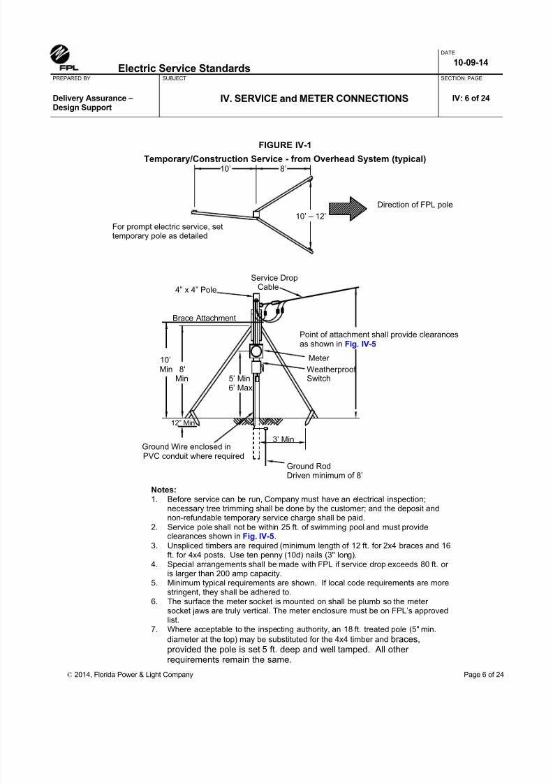
8/18/2019 electric-service-standards Florida Power Light FPL.pdf
http://slidepdf.com/reader/full/electric-service-standards-florida-power-light-fplpdf 39/118
Electric Service Standards
DATE 10-09-14
PREPARED BY SUBJECT
IV. SERVICE and METER CONNECTIONS
SECTION: PAGE
Delivery Assurance –Design Support
IV: 6 of 24
© 2014, Florida Power & Light Company Page 6 of 24
FIGURE IV-1
Temporary/Construction Service - from Overhead System (typical)
4” x 4” Pole
10’Min 8'
Min 5’ Min6’ Max
Ground Wire enclosed inPVC conduit where required
Meter
For prompt electric service, settemporary pole as detailed
Direction of FPL pole
Service DropCable
Point of attachment shall provide clearancesas shown in Fig. IV-5
WeatherproofSwitch
Notes:1. Before service can be run, Company must have an electrical inspection;
necessary tree trimming shall be done by the customer; and the deposit andnon-refundable temporary service charge shall be paid.
2. Service pole shall not be within 25 ft. of swimming pool and must provideclearances shown in Fig. IV-5.
3. Unspliced timbers are required (minimum length of 12 ft. for 2x4 braces and 16ft. for 4x4 posts. Use ten penny (10d) nails (3" long).4. Special arrangements shall be made with FPL if service drop exceeds 80 ft. or
is larger than 200 amp capacity.5. Minimum typical requirements are shown. If local code requirements are more
stringent, they shall be adhered to.6. The surface the meter socket is mounted on shall be plumb so the meter
socket jaws are truly vertical. The meter enclosure must be on FPL’s approvedlist.
7. Where acceptable to the inspecting authority, an 18 ft. treated pole (5" min.
diameter at the top) may be substituted for the 4x4 timber and braces,provided the pole is set 5 ft. deep and well tamped. All otherrequirements remain the same.
12” Min
Ground RodDriven minimum of 8’
3’ Min
10’ 8’
Brace Attachment
10’ – 12’

8/18/2019 electric-service-standards Florida Power Light FPL.pdf
http://slidepdf.com/reader/full/electric-service-standards-florida-power-light-fplpdf 40/118
Electric Service Standards
DATE 10-09-14
PREPARED BY SUBJECT
IV. SERVICE and METER CONNECTIONS
SECTION: PAGE
Delivery Assurance –Design Support
IV: 7 of 24
© 2014, Florida Power & Light Company Page 7 of 24
FIGURE IV-2 Temporary/Construction Service - from Underground System (typical)
See Note 2
Bushing
Angle Braces 4X4 Treated Post
Customer's weatherprooffuse switch installation shallcomply with local code.
Angle Braces onlynecessary in unstable
soil.
4x4 treated wood post, slotted angle, orangle iron support for switch and meter.
If desired, customer's switch may be above meter, if postand angle braces are extended to give needed height.
3' Min6’ Max
3' See Note 2
Service Handhole
Ground wire to groundingelectrode or Ground Rod.(See Note 3)
Customer'sPVC conduit forground wire
Meter Customer's Meter Socket
Customer's conduitin accordance withlocal code authority
Notes:1. Before service can be connected, the company must have the electrical inspection; necessary grading shall be done by the
customer; and the deposit and non-refundable temporary service charge shall be paid. Contact the FPL representative foravailability and location.
2. The customer shall leave a five foot length of service conductor above ground, outside of source, for connection to FPL secondaryby FPL.
3. Temporary service should be located outside the utility easement to avoid driving the ground rod into any existing underground
cables.4. Service Conductors shall be near secondary side of the transformer . 5. The meter enclosure must be on FPL’s approved list.
Padmounted Transformer

8/18/2019 electric-service-standards Florida Power Light FPL.pdf
http://slidepdf.com/reader/full/electric-service-standards-florida-power-light-fplpdf 41/118
Electric Service Standards
DATE 10-09-14
PREPARED BY SUBJECT
IV. SERVICE and METER CONNECTIONS
SECTION: PAGE
Delivery Assurance –Design Support
IV: 8 of 24
© 2014, Florida Power & Light Company Page 8 of 24
FIGURE IV-3
FPL Electric Service and Meter Socket Requirements Form
APPLICANT Current FPL Account No. _____________________
MAILING ADDRESS CITY, ZIP CODE __________ ______________
SERVICE ADDRESS/LEGAL DESCRIPTION
PHONE (WEEKDAYS) DATE _____________________ _______
FPL is pleased to advise that electric service for your proposed will be available from our Distribution facilities as shownon the sketch below. We understand you are requesting Overhead Underground, volts, phase service. The items checked belowand receipt by our representative of the white copy of this form with your signature acknowledging your receipt, are required before FPL provideselectric service:
Payment:(Check orMoney Order)
Construction/Temporary Service Charge: $ _________
Security Deposit for Construction/Temporary Service: $ _________
Underground/Overhead Differential Charge for Permanent Service: $ _________
Line Extension Contribution In Aid of Construction (CIAC): $ _________
Total: $ __________
Tree Trimming & Clearing: Feet
Each Side of Proposed LineInstallation of Meter Socket & Downpipe/Weatherhead according to FPL Specifications
(see checklist on reverse side of this sheet)Install eyebolt (for FPL to attach wires to)Configuration Meter Socket*
*Meter socket must be approved for use in FPL service area.Current list of approved sockets available upon request. Socketconfigurations are shown on reverse side of this form.
Site Plan Electrical Load Information/PlansEasement for FPL Facilities/Legal Description of PropertyContact FPL days before Certificate of Occupancyconcerning Application/Security Deposit for permanent
service.
Final City/County Electrical Inspection
$ Security Deposit is required before will be billed after
permanent service provided. Other:
For overhead service, minimum attachment height is to be 12 feet above grade. For underground service, minimum cover is to be 24 inches(maximum 36 inches). FPL specifications and requirements must be adhered to and are available upon request. Upon timely completion of theabove required items and agreement between you and our Representative, service may be provided approximately the week of or asmutually agreed upon. Changes to type service requested, failure to comply with above requirements, or delays to FPL's construction schedule mayaffect proposed date of service.
"SERVICE LOCATION SKETCH" INDICATE NORTH
PLEASE SIGN ON THE LINE PROVIDED BELOW, RETAIN A COPY AND RETURN A COPY TO FPL.
RECEIPT IS HEREBY ACKNOWLEDGED: MAKE INQUIRIES TO:
APPLICANT DATE
TITLE (IF CORPORATION)
BY (OTHER THAN APPLICANT)

8/18/2019 electric-service-standards Florida Power Light FPL.pdf
http://slidepdf.com/reader/full/electric-service-standards-florida-power-light-fplpdf 42/118
Electric Service Standards
DATE 10-09-14
PREPARED BY SUBJECT
IV. SERVICE and METER CONNECTIONS
SECTION: PAGE
Delivery Assurance –Design Support
IV: 9 of 24
© 2014, Florida Power & Light Company Page 9 of 24
FIGURE IV-4 Guide for Locating Point of Delivery on Outside of Building
Overhead Electric Supply
Underground Electric Supply
OH
Fence
Preferred Point ofDelivery Location(outside of fence)
Underground Secondary (URD)
Street
UGOH or UG
Utility Easement
Utility Easement
P/L
P/L
P/L
Customer’s Buildingor Residence

8/18/2019 electric-service-standards Florida Power Light FPL.pdf
http://slidepdf.com/reader/full/electric-service-standards-florida-power-light-fplpdf 43/118
Electric Service Standards
DATE 10-09-14
PREPARED BY SUBJECT
IV. SERVICE and METER CONNECTIONS
SECTION: PAGE
Delivery Assurance –Design Support
IV: 10 of 24
© 2014, Florida Power & Light Company Page 10 of 24
FIGURE IV-5 Overhead Service - Minimum Vertical Clearances
FIGURE IV-6a
Drip Loop
B
A C
C
C
C
A. Roads, streets and other areas subject to truck traffic .............................................................................. 16 feet (NEC = 18')
B. Driveways, parking lots and alleys .............................................................................................................. 15 feet (NEC = 18')Exception - Residential driveways only where attachment height at building does not permit 15 feet of clearance:
Voltage limited to 300v to ground:Service Drops ................................... 12.5 feet (NEC = 12')Drip Loops ....... ....... ....... ........ ....... .... 10.5 feet (NEC = 12')
Voltage limited to 150v to ground:Service Drops ....... ....... ....... ........ ....... .. 12 feet (NEC = 12')Drip Loops ....... ....... ....... ........ ....... ....... 10 feet (NEC = 12')
C. Spaces and ways subject to pedestrian or restricted traffic only .............................................................. 12 feet (NEC = 12')Exception - Where attachment height at building does not permit 12 feet of clearance:
Voltage limited to 300v to ground:Service drops and drip loops .. ..... 10.5 feet (NEC = 12')
Voltage limited to 150v to ground:Service drops and drip loops .. ........ 10 feet (NEC = 10')
D. Other land (such as cultivated, grazing, forest, orchard, etc.) traversed by vehicles .............................. 16 feet (NEC = 18')
NOTES:-120v single phase, 120/240v single phase, and 120/208v wye 3 phase services meet the 150v to ground criteria.-120/240v open or closed delta 3 phase and 277/480v wye 3 phase services meet the 300v to ground criteria.-240/480v delta services do not meet either the 150v or 300v to ground criteria and do not qualify for the exception to the basic clearance.The clearances above are NESC minimum values for worst-case sag conditions. The attachment height at the building or customer's servicepole must be sufficient to provide these clearances for all situations involved. Good judgment dictates that initial installation be made at highervalues to ensure code compliance under worst-case sag conditions. For additional details and clarification regarding these and all clearances,refer to Article 23 of the NESC.
MINIMUM VERTICAL CLEARANCE ABOVE GRADE (from NESC Table 232-1)Multiplexed overhead service drops of 750v to ground or less located more than 10 feet
horizontally from a swimming pool

8/18/2019 electric-service-standards Florida Power Light FPL.pdf
http://slidepdf.com/reader/full/electric-service-standards-florida-power-light-fplpdf 44/118
Electric Service Standards
DATE 10-09-14
PREPARED BY SUBJECT
IV. SERVICE and METER CONNECTIONS
SECTION: PAGE
Delivery Assurance –Design Support
IV: 11 of 24
© 2014, Florida Power & Light Company Page 11 of 24
Attachment of Service Drop at Buildings - to the Pipe Mast
Maximum Service Bracketattachment height above last
firm support (A)
Diameter(Inches)
Rigid Metallic*or IMC (feet)
2 2.5
2-1/2 4.75
3 7.66
3-1/2 10.66
Grounding Electrode per current NEC requirements
*Rigid Metallic shall be per ANSI C-80.1 and shall be hotdipped galvanized inside andout.
Triplexed Service Drop withbare neutral, less than 750volts.
ServiceBracket
6” Min.
(A)
FinishedGrade
SWITCH
18” Min.
See Note 8
10 ft. Min.150v to Ground
(refer to Fig. IV-5)
5' Min.6' Max.
Min. 36” clearanceto any obstruction
Notes:1. A service Mast may be used to get proper clearance if permitted by local code.2. The Service Drop and Service Bracket are provided and installed by FPL.3. Service Mast or other approved attachment post or bracket must be sufficient strength to support the Service
Drop. 2” or larger rigid galvanized conduit is preferred. The point of attachment must be sufficient height to
provide minimum clearances. FPL will not attach Service Drop to an aluminum, EMT, or PVC mast.4. Customer provides and installs Service Mast in accordance with National Electrical Code and/or local codes.5. Minimum clearance to Drip Loops is 10 feet from ground. Minimum Drip Loop to Roof clearance is 18 inches.6. Service Drop, Service Bracket and Meter are owned and installed by FPL. Meter Socket is owned, installed
and maintained by customer.7. Service Drop clearance required at locations other than a house are shown in Fig. IV-5.8. For triplexed or quadraplexed cable services, less than 750 volts, with bare neutral, the 18” minimum
clearance is allowed only where no more than 6 feet, measured horizontally, of the service drop passes overa roof to terminate at a through-the-roof mast located not more than 4 feet, measured horizontally, from thenearest edge of the roof. Otherwise, the minimum clearance above the roof (not readily accessible) of thebuilding to which the service is attached is 3 feet. Refer to NESC 234C3d.

8/18/2019 electric-service-standards Florida Power Light FPL.pdf
http://slidepdf.com/reader/full/electric-service-standards-florida-power-light-fplpdf 45/118
Electric Service Standards
DATE 10-09-14
PREPARED BY SUBJECT
IV. SERVICE and METER CONNECTIONS
SECTION: PAGE
Delivery Assurance –Design Support
IV: 12 of 24
© 2014, Florida Power & Light Company Page 12 of 24
FIGURE IV-6bAttachment of Service Drop at Buildings - to the Structure
NOTE: Where local building codes are more conservative, they take precedence.
5/8" Bolt with Eyenut castin concrete tie beam
3/8” x 3-1/2” GalvanizedSteel Screw Eye
If point of service attachment can bedetermined before construction, an
effort should be made to have eyeboltinstalled during construction
ALTERNATIVE #1
When attachment must be made tobuilding frame use 3/8” x 3-1/2” screw eye.Drill thru siding with 3/8” bit. Use1/4“ bit to
precede screw into stud.
ALTERNATIVE #2
Use toggle screw eye on hollow tile orconcrete block walls
ALTERNATIVE #3
Use expansion screw eye in pouredconcrete walls or beam
ALTERNATIVE #4
3/8” x 2-1/8” GalvanizedSteel Expansion Screw Eye5/16” x 5” Galvanized SteelToggle Screw Eye

8/18/2019 electric-service-standards Florida Power Light FPL.pdf
http://slidepdf.com/reader/full/electric-service-standards-florida-power-light-fplpdf 46/118
Electric Service Standards
DATE 10-09-14
PREPARED BY SUBJECT
IV. SERVICE and METER CONNECTIONS
SECTION: PAGE
Delivery Assurance –Design Support
IV: 13 of 24
© 2014, Florida Power & Light Company Page 13 of 24
FIGURE IV-6cAttachment of Service Drop at Buildings - to the Wood Eave
See Note 2
Closed EaveFascia Board
Direction of Pull Install Service Strapwith Grooved Nails thru Boxing intobottom edge of rafter
Boxed Eave
Exposed Eave
Fascia BoardService Bail
ServiceStra DETAIL OF
ATTACHMENT STRAP
TYPICAL METHODS
To be used only when anchorage into wall will not provide proper ground clearance
Attachment to anymember not firmlyanchored should beavoided
See Note 2
Notes:1. Attach Service Strap with 2-1/2", No. 8 gauge "Anchor Fast" grooved nails.2. If angle between Service Strap and Service Cable is greater that 45 degrees, the
strap should be attached on side of rafter opposite direction of Service Pull.
Direction of P

8/18/2019 electric-service-standards Florida Power Light FPL.pdf
http://slidepdf.com/reader/full/electric-service-standards-florida-power-light-fplpdf 47/118
Electric Service Standards
DATE 10-09-14
PREPARED BY SUBJECT
IV. SERVICE and METER CONNECTIONS
SECTION: PAGE
Delivery Assurance –Design Support
IV: 14 of 24
© 2014, Florida Power & Light Company Page 14 of 24
FIGURE IV-7 Outdoor Meter Installation - 1ph 120/240v 3 wire Overhead Service
Grounding Bushing(Required for
Concentric & EccentricKnockout with
Retaining Rings)
DETAIL "A" BONDING AROUND CONCENTRIC & ECCENTRIC KNOCKOUTS
Mount Meter Socket Securelyand level in Horizontal and
Vertical Planes
Mount Through 4Mounting Holes Only
Load Hot Le s
Neutral Line Hot Legs
3-WIRE, 120/240V 1phMeter Symbol "C"
SEE DETAIL "A"
To ServiceEquipment
FPL furnishes, installs, and maintainsservice drop and makes connectionto customer's service entrance conductors
For service dropclearance,
see Fig IV-5
FPL furnishes anchor bolt to be installedby customer (no further than 24" from mast)
Customer furnishes, installs and maintains serviceentrance conductors and conduit (per local code)
Mount meter socket securely andlevel in horizontal and verticalplanes
3 ft. minimum horizontalclearance to buildingopenings, etc.
10' Min.
25' Max.6' Max.5’Min.
Finished
Grade
6" Min. 12"Min.
To Weatherhead(see Fig. IV-8, Detail "A")
Customer to Attach ConduitThrough Knockout Bottom orBack of Meter Socket
NOTE: Customer must provide adequategrounding of facilities in accordance with the NECand local codes.
Customer must identifyneutral at weatherhead
Customer to Furnish and InstallGrounding Bushing & Bonding Conductorwhere required by National Electric Code

8/18/2019 electric-service-standards Florida Power Light FPL.pdf
http://slidepdf.com/reader/full/electric-service-standards-florida-power-light-fplpdf 48/118

8/18/2019 electric-service-standards Florida Power Light FPL.pdf
http://slidepdf.com/reader/full/electric-service-standards-florida-power-light-fplpdf 49/118
Electric Service Standards
DATE 10-09-14
PREPARED BY SUBJECT
IV. SERVICE and METER CONNECTIONS
SECTION: PAGE
Delivery Assurance –Design Support
IV: 16 of 24
© 2014, Florida Power & Light Company Page 16 of 24
FIGURE IV-9 Lug-Type Meter Socket Installations
In underground installations, when customer’s conductors are parallel, customers conductors MUST be keptentirely to one side of the meter can, leaving the opposite side of the meter can unobstructed for FPL’sconductor. When load conductors enter through the bottom rear of the meter can they must be kept entirely toone side so not to interfere with the FPL conductor.
BellevilleWasher
BellevilleWasher
FlatWasher
NOT ACCEPTABLE ACCEPTABLE PROPER INSTALLATION OF WASHERS & LUGS ON LUG-TYPE METER CANS
Be sure the flat washer is placed between the Belleville Washer and the wire lug. This installation will ensurethe maximum surface contact area of the lug and the meter block.
Be sure the wire is placed properly in the lug so it will not interfere with the tightening of the Belleville Washer.
The lug used in the 400 amp (K-7) and 600 amp (K-7T) cans must have an anti-rotation ridge as shown. This ridge isnot required in smaller cans.
Meter BlockLUGWIRE WIRE
LUG
Anti-Rotation Ridge mustbe on lugs used in K-7 &K-7T type cans.
MeterBlock
FlatWasher
MAIN
LINE
SWITCH
TROUGH
(LINE GUTTER)
METER
CAN
METER
CAN
DOWNPIPE FOR FPL SERVICE
DOWNPIPE FOR
FPL SERVICE
METER
CAN
***NOT ACCEPTABLE******ACCEPTABLE CONFIGURATIONS***
Mains may only
extend from ONE
side of meter can,
on OPPOSITE
side of meter can
from Downpipe
MAIN
LINESWITCH
MAIN
LINE
SWITCH
MAIN
LINE
SWITCH
MAIN
LINE
SWITCH
MAIN
LINE
SWITCH
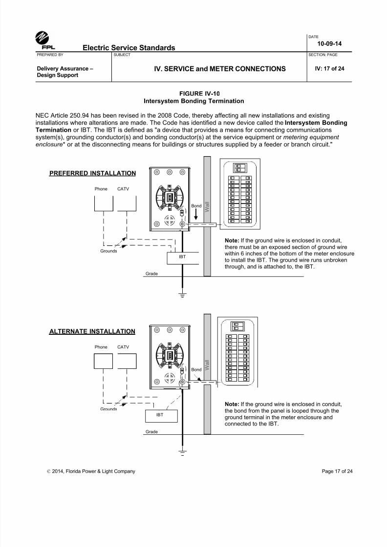
8/18/2019 electric-service-standards Florida Power Light FPL.pdf
http://slidepdf.com/reader/full/electric-service-standards-florida-power-light-fplpdf 50/118
Electric Service Standards
DATE 10-09-14
PREPARED BY SUBJECT
IV. SERVICE and METER CONNECTIONS
SECTION: PAGE
Delivery Assurance –Design Support
IV: 17 of 24
© 2014, Florida Power & Light Company Page 17 of 24
FIGURE IV-10Intersystem Bonding Termination
NEC Article 250.94 has been revised in the 2008 Code, thereby affecting all new installations and existinginstallations where alterations are made. The Code has identified a new device called the Intersystem BondingTermination or IBT. The IBT is defined as "a device that provides a means for connecting communicationssystem(s), grounding conductor(s) and bonding conductor(s) at the service equipment or metering equipment
enclosure* or at the disconnecting means for buildings or structures supplied by a feeder or branch circuit."
W a l l
W a l l
PREFERRED INSTALLATION
ALTERNATE INSTALLATION
Phone CATV
Grounds
IBT
IBT
Phone CATV
Grounds
Note: If the ground wire is enclosed in conduit,there must be an exposed section of ground wirewithin 6 inches of the bottom of the meter enclosureto install the IBT. The ground wire runs unbrokenthrough, and is attached to, the IBT.
Note: If the ground wire is enclosed in conduit,the bond from the panel is looped thr ough theground terminal in the meter enclosure andconnected to the IBT.
Bond
Bond
Grade
Grade

8/18/2019 electric-service-standards Florida Power Light FPL.pdf
http://slidepdf.com/reader/full/electric-service-standards-florida-power-light-fplpdf 51/118
Electric Service Standards
DATE 10-09-14
PREPARED BY SUBJECT
IV. SERVICE and METER CONNECTIONS
SECTION: PAGE
Delivery Assurance –Design Support
IV: 18 of 24
© 2014, Florida Power & Light Company Page 18 of 24
FIGURE IV-11aURD System Layout - Typical
Service Lateralin Conduit
P/L
P/L
Meter
5' Meter
Primary Cable
10'
Easement (typical)
5' Service Lateral
in Conduit
Primary Cable
Sidewalk
Street
Transformer
NOTES: (APPLICABLE TO FIGURES 11a and 11b)1. Backfill adjacent to cable must be free of boards, debris, and rocks larger than 1” in diameter.2. Aim service conduit towards designated source of Company’s service. End of conduit must be at
least 24” away from any permanent structure (patio, porch, etc.) measured at right angle fromthe structure. Cap or plug the end of pipe.
3. The service lateral must cross the property line within the limits of the easements and should bein a direct line to meter as nearly as practical. It must have at least 5’ horizontal clearance to anyswimming pool.
4. Conduit bend requirement of National Electrical Code Section 346-10 “the internal diameter ofthe conduit will not be effectively reduced.”
5. With FPL approval, slight variances in customer’s downpipe size may be accepted if suitable
adapter fitting is also provided by the customer. For example, 2-½”downpipe may be accepted ifadapter to FPL 2” PVC conduit is provided.6. Conductor sizes shown in tables are for triplex cables.7. If load conductors enter from the side, entrance must be opposite side of FPL conductors.
When two load conduits are used, they must be kept to one side of the can, allowing spacefor the line conductors. See Figure IV-9. Center position may not be used for the downpipe.
8. Schedule 80 PVC is acceptable to use, where an obstruction exists at the downpipe thecustomer must extend the service conduit a minimum of 24" past the obstruction. FPL willprovide the 90 degree bend, if the customer provides the 90 degree bend it must be a 24" radiusbend. Field Bends are NOT acceptable!

8/18/2019 electric-service-standards Florida Power Light FPL.pdf
http://slidepdf.com/reader/full/electric-service-standards-florida-power-light-fplpdf 52/118
Electric Service Standards
DATE 10-09-14
PREPARED BY SUBJECT
IV. SERVICE and METER CONNECTIONS
SECTION: PAGE
Delivery Assurance –Design Support
IV: 19 of 24
© 2014, Florida Power & Light Company Page 19 of 24
FIGURE IV-11b FPL Buried Service Lateral – Meter Socket & Down Pipe Requirements(references to notes shown in Figure IV-11a)
Wire SizeCu or Al
Downpipe 90 Degree Bends 45 Degree Bends
Bends Radius Bends Radius
1/0 or 4/0 2” (1) 2” – 90 24” (2) 2” – 45 18”
2 – 4/0 2 – 2” (2) 2” – 90 24” (4) 2” – 45 24”
2 – 4/0 4” (1) 4” – 90 36” (2) 4” – 45 24”
6’ Max.5’ Min.
Customer supplied andinstalled meter socket
FPL Service Cable in Conduit to padmountedtransformer, handhole, or riser (See Notes 1 & 3)
See Table A(90 deg bends)
See Table A(45 deg bends)
Strap conduit to wall
Grade Grade
Neutral
FPLServiceConductors(by FPL)
Line Load
Customer’s ServiceEntrance Conductors
(by Customer)
Typical meter cansupplied and installedby the Customer
If Load Conductors enter fromthe side, Entrance must be
opposite side of FPLconductors. See Fig. IV-9.
Center positions may not beused for downpipe.
IMPORTANT – Please distinguish between Overhead and Underground (URD)meter sockets when purchasing. (See FPL Approved List in Section VII).
Note: If FPL Service Conductors (line side) are parallel #4/0 triplex, then thecustomer shall provide and install connectors designed for multiple conductors inthe meter socket.
Table A
24” Min. 36” Max.(24” Preferred)
24” Min. 36” Max.(24” Preferred)
24” Min. 36” Max.(24” Preferred)
24” Min.
6’ Max.5’ Min.
Customer 2” or 4”Rigid Galvanized,Intermediate, or
Schedule 80 PVC(Notes 2 & 8)
Customer supplied andinstalled meter socket
Customer 2” or 4”Rigid Galvanized,Intermediate, or
Schedule 80 PVC
(Notes 2 & 8)
Customer 2” or 4”Rigid Galvanized,Intermediate, or
Schedule 80 PVC
(Notes 2 & 8)
Strap conduit to wall
Customer supplied andinstalled meter socket
6’ Max.5’ Min.
Strap conduit to wall
PREFERRED METHOD
(Using 90 degree bends)
ALTERNATE METHOD
(Using 2-45 degree bends)
EXTENDING CONDUIT 24” BEYOND OBSTRUCTIONS
See Note 8
FPL Service Cable in Conduit to padmountedtransformer, handhole, or riser (See Notes 1 & 3)
FPL Service Cable in Conduit to padmountedtransformer, handhole, or riser (See Notes 1 & 3)
Grade

8/18/2019 electric-service-standards Florida Power Light FPL.pdf
http://slidepdf.com/reader/full/electric-service-standards-florida-power-light-fplpdf 53/118
Electric Service Standards
DATE 10-09-14
PREPARED BY SUBJECT
IV. SERVICE and METER CONNECTIONS
SECTION: PAGE
Delivery Assurance –Design Support
IV: 20 of 24
© 2014, Florida Power & Light Company Page 20 of 24
FIGURE IV-12bResidential Multiple Occupancy Buildings - Multiple Meter Center
1/16" Min. hole in circuit
breaker handle
2"
Multiple Meter Center must appear on the Approved List *Residential Application Shown
IF 'B'
Min.
36"
42" 22"
36"
THEN 'A'
Min.
'D'
'F'
'F'
'F'
'F'
'F'
'F'
'F'
'F'
'F'
'F'
'F'
'F'
'F'
'F'
'F'
'E'
'E'
'E'
'E'
'E'
'E'
'E'
'E'
'E'
'E'
'E'
'E'
'E'
'E'
'E'
'J' - Apartment Number on
BOTH Switch and Meter
'I'
* Non-residential and 3 phase applications require lever by-pass, jaw tension/release socket blocks
Load Gutter 'H' 'H' Center Line of Bottom Meters
"A"
50" Max.
72" Max. to Centerline of top meters
Horizontal clearance of meter face to opposite wall or equipment thereon. Approved captive screw-type sealing ring when socket is ring type. Provision for sealing each breaker 'F' in off position. Common trip load breaker for each unit. Breakers are preferred on load side of meter socket. Fiber or metal barrier at these points to separate line wires from metered circuits. Fiber or metal barrier at these points to separate metered circuits from line busses. Permanent and durable identification must be placed on both meter and breaker face plates.
Fifth terminal to be provided when used on 120/208 volt three wire, and is acceptable only in the 9 O'clock position as shown.
'B' - 'D' - 'E' - 'F' - 'G' - 'H' - 'J' -
'I' -
FRONT VIEW
Line Gutter Wiring Gutter
Main Switch
Service Entrance Conduit
Center Line of Meters 'G' 'G'
METER ROOM SIDE VIEW
'B'
Line Gutter
Load Gutter
'A'
Details for sealing Circuit Breaker at 'E'
BREAKER
Minimum Height o C/L of
Lowest Meter
Finished
Floor
Lead Seal and copper wire
'G'
'H'
1/16" Min. hole in Angle
Also, mark the inside of the enclosure when possible to do so.

8/18/2019 electric-service-standards Florida Power Light FPL.pdf
http://slidepdf.com/reader/full/electric-service-standards-florida-power-light-fplpdf 54/118
Electric Service Standards
DATE 10-09-14
PREPARED BY SUBJECT
IV. SERVICE and METER CONNECTIONS
SECTION: PAGE
Delivery Assurance –Design Support
IV: 21 of 24
© 2014, Florida Power & Light Company Page 21 of 24
FIGURE IV-13a Remote Meter Location, Typically used for Service to a Mobile Home
6’ Max.5’ Min.
5’ Min.
Meter (See note 8)
See note 5
Service Entrance – by customer
Pole (See note 7)
12”Service Drop – by FPL
See note 7
Grade
Ground(See note 4)
Customer Ownedand Installed
To Mobile HomeService (See note 6)
Post(See note 2)
Main Service Disconnect(See note 3)
Meter – FPL Ownedand Installed
(See note 8)
48” Max.36” Min.
CustomerOwned and
Installed
Grade
Conduit(2” min.)
Aim Conduit towardSecondary Source
Buried Cable inConduit – FPLOwned and Installed
NOTES:
1. Space under meter socket on post to be reserved for conduit.2. Post to be constructed of reinforced concrete (5"x5"), fiberglass (6”x6” minimum), pressure
treated wood (4”x4” minimum), 2" galvanized steel pipe with 2" concrete encasement belowground level, or equivalent.
3. Circuit breaker or main service fused disconnect (outdoor type) National Electrical Code.4. The customer must ground facilities as required by the National Electrical Code and
applicable local codes (refer to section VIII of this FPL Electric Service Standards issue).5. Customer will install a sufficient number of conduit straps to properly secure conduit to pole.6. Customer service may be run underground in conduit from bottom of main switch.7. Customer's class 6 or 7 pressure treated wood pole, or equivalent, set a minimum of 5' deep.
Must provide minimum service drop clearances shown in Figure IV-5.
8. Meter - Furnished and installed by FPL. Meter socket furnished and installed by customer.
Class Chart for Douglas Fir and Southern Yellow Pine Poles
LengthMinimum circumference at top Minimum circumference 6’ from buttClass 6 Class 7 Class 6 Class 7
20’ 17” 15” 21” 19.5”25’ 17” 15” 23” 21.5”30’ 17” 15” 25” 23.5”35’ 17” 15” 27” 25”

8/18/2019 electric-service-standards Florida Power Light FPL.pdf
http://slidepdf.com/reader/full/electric-service-standards-florida-power-light-fplpdf 55/118
Electric Service Standards
DATE 10-09-14
PREPARED BY SUBJECT
IV. SERVICE and METER CONNECTIONS
SECTION: PAGE
Delivery Assurance –Design Support
IV: 22 of 24
© 2014, Florida Power & Light Company Page 22 of 24
FIGURE IV-13bPedestal Service - Customer Provided Meter Pedestal (typical)
Meter pedestal must be rigid enough to withstandforce applied when meters are installed.
Service Equipment (Outdoor Type) in accordance with N.E
Seal
Grounding Electrode Conductor
Notes:1. Meter pedestal must be on FPL's approved list, and equipped with standard meter
socket.2. Where FPL is providing the service lateral to the pedestal, refer to Figure IV-11b for
downpipe specifications.
3. FPL Conductors may terminate in customer owned pedestal, but are not to be loopedin and out of pedestal.
4. Meter pedestals may be used for residential services or for commercial installationsserving non-critical loads. Refer to IV-A.1 for examples.
48" Max. 36" Min.
24" Min.
The customer must ground facilities as requiredby the National Electrical Code and applicablelocal codes. See Section VIII of these FPLElectric Service Standards.
36" Min.
Customer Owned Meter Pedestal
To Transformer, pole,or handhole (in conduit)

8/18/2019 electric-service-standards Florida Power Light FPL.pdf
http://slidepdf.com/reader/full/electric-service-standards-florida-power-light-fplpdf 56/118
Electric Service Standards
DATE 10-09-14
PREPARED BY SUBJECT
IV. SERVICE and METER CONNECTIONS
SECTION: PAGE
Delivery Assurance –Design Support
IV: 23 of 24
© 2014, Florida Power & Light Company Page 23 of 24
FIGURE IV-13cMobile Home Service - "Grouped" Service to Mobile Homes
Grade
LOT1 LOT2
LOT2 LOT1
Main Service Fused Disconnect or Circuit Breaker(Outdoor Type) sized according to the NationalElectrical Code.
Typical Meter Owned andInstalled by FPL
To Mobile Homes(by customer)
Customer Owned and InstalledConduit (see note 2 below)
To Transformer, pole,or handhole (in conduit)
Meter Sockets Providedand Installed by Customer
When there are 4 meters,mount 2 here.
2"x5/8" Galvanized SteelChannel or Equivalent
The customer must ground facilities as required bythe National Electrical Code and applicable local codes. See Section VIII of these FPL Electric Service Standards.
NOTES:
1. Customer must permanently and durably mark exterior of meter socketand switch to indicate which unit they serve. Also mark the inside ofthe enclosure when it is feasible to do so.
2. Where FPL is providing the service lateral to the pedestal, refer toFigure IV-11b for downpipe specifications.
3. Where FPL is providing the service lateral to the pedestal, a maximumof 4 units is allowed per pedestal.
4. Where FPL is providing the service lateral to the pedestal, FPLconductors will terminate in customer owned pedestal (they'll not belooped in and out of pedestal).
24" Min. 36" Min.
36" Min. 48" Max.
Post to be constructed of reinforcedconcrete (5"x5"), 4"x4" pressuretreated wood, 2" galvanized steelpipe with 2" concrete encasementbelow ground level, or equivalent.
Grade

8/18/2019 electric-service-standards Florida Power Light FPL.pdf
http://slidepdf.com/reader/full/electric-service-standards-florida-power-light-fplpdf 57/118
Electric Service Standards
DATE 10-09-14
PREPARED BY SUBJECT
IV. SERVICE and METER CONNECTIONS
SECTION: PAGE
Delivery Assurance –Design Support
IV: 24 of 24
© 2014, Florida Power & Light Company Page 24 of 24
FIGURE IV-14Identification of Customer Cables
ADDRESS
Customer Owned
DATE
INSTALLER
FPL/CONTRACTOR
CREW #
DIRECT BURIED AND CABLE IN CONDUIT SYSTEMS
Use plastic tags as shown in Figure 1 for customer identification at locations that will be subjected to sunlight, such as
risers, and also in URD applications for identifying services, such as padmounted transformers and handholes. Plastic tags
should have a clear, UV resistant flap to reduce fading and weathering. Use indelible (permanent) marker, and allow 10
seconds drying time to prevent smearing before adhering flap. Fasten tag to cable using plastic tie wraps. Blank tags are
available upon request.
To HHEast
To TXWest
To HHEast
To HHWest
#3928
(Service to #3928)ST LTSN&W
(2 Lights)
(Street Light Circuit)
#3950
Tag each service in the TXwith address served
2 ½”
2 ½”
Example of proper service tagging:
Figure 1: Service Tag

8/18/2019 electric-service-standards Florida Power Light FPL.pdf
http://slidepdf.com/reader/full/electric-service-standards-florida-power-light-fplpdf 58/118
Electric Service Standards
DATE
01-28-11
PREPARED BY SUBJECT
V. REQUIREMENTS FOR TRANSFORMERSSITUATED ON CUSTOMER PROPERTY
SECTION: PAGE
Delivery Assurance –
Desi n Su ortV: 1 of 6
© 2011, Florida Power & Light Company Page 1 of 6
V. REQUIREMENTS FOR TRANSFORMERS SITUATED ON CUSTOMER PROPERTY
A. Padmounted Transformer Requirements
Complete requirements are contained in FPL specifications given to Customers for individual
projects. Typical pad mounted transformer requirements include, but are not limited to the
following:
The Customer Will:
- provide a transformer pad location per FPL specifications. For residential dwelling units, the
transformer shall not be located closer than 15 feet from a door or window to the habitable
portion of the dwelling unit (to minimize noise problems);
- pour and cure the concrete pad according to FPL specifications, or install the FPL supplied pre-
cast pad, for transformers sized 750 KVA and larger;
- bring the service entrance conductors out to the transformer, installed in accordance withNational Electrical Code requirements, leaving adequate cable, as determined by FPL, for FPL
to make connections in the transformer, the number of cables limited as shown below:
Transformer
KVA
Secondary
Voltage
Max.
Number of
Conductors
Max. Conductor
Size
Max. Number of
Conduits & Sizes
25 – 167
(Low Style)
120/240V 8 sets 4/0 8 – 2” Max
25 – 167
(High Style)
120/240V 8 sets 750 KCMIL 8 – 2” Max
6 – 3.5” Max
4 – 4” Max150 – 500 120/208V
277/480/V
8 sets 750 KCMIL 8 – 4” Max
750 277/480V 8 sets 750 KCMIL 8 – 5” Max
750 120/208 V 12 sets* 750 KCMIL 12 – 5” Max
1000 277/480V 12 sets* 750 KCMIL 12 – 5” Max
1000 120/208V 12 sets* 750 KCMIL 12 – 5” Max
1500 - 2000 277/480V 12 sets* 600 – 750 KCMIL 12 – 5” Max
1500 - 2000 277/480V 14 sets* 500 KCMIL or less 14 – 5” Max
2500 277/480V 12 sets* 600 – 750 KCMIL 12 – 5” Max
2500 277/480V 16 sets* 500 KCMIL or less 16 – 5” Max
*An FPL provided secondary connection cabinet is recommended for new installations with
more than 8 sets of 750 KCMIL or more than 12 sets of a smaller size conductor.
- maintain access to FPL to padmounted equipment located on the Customer's property (eight
feet of clearance from the door side and three feet of clearance from other sides from items
such as fences, shrubs and other obstructions are to be maintained by the Customer, as shown

8/18/2019 electric-service-standards Florida Power Light FPL.pdf
http://slidepdf.com/reader/full/electric-service-standards-florida-power-light-fplpdf 59/118
Electric Service Standards
DATE
01-28-11
PREPARED BY SUBJECT
V. REQUIREMENTS FOR TRANSFORMERSSITUATED ON CUSTOMER PROPERTY
SECTION: PAGE
Delivery Assurance –
Desi n Su ortV: 2 of 6
© 2011, Florida Power & Light Company Page 2 of 6
in Fig. V-1. FPL will help plan the Customer's installations of fences, shrubs, etc. near FPLfacilities such that they will not obstruct access or cause damage to FPL's facilities. Where
adequate access to FPL facilities is maintained, faster service restoration is made possible in
the event of a power interruption.);
- provide suitable barriers, if specified by FPL, to protect the padmounted transformer and
associated metering equipment from vehicular traffic;
- provide FPL with a suitable easement for the pad and distribution cables, including the right to
install additional cables to serve other Customers, as required;
- clear trench route, have to grade, as specified in section II.E;
- conform to the requirements of the National Electrical Code and applicable local codes
(approval from the local inspecting authority shall be provided to FPL before FPL will connect
service).
FPL Will:
- provide transformer specifications to the Customer;
- determine if a secondary connection cabinet will be required;
- provide and install the transformer, the concrete pad (if applicable), and the primary cable and
conduit.
If only one, single-meter Customer is served (greater than 600 amps), and no future additional
meters will be connected, current transformers may be placed in padmounted transformer before
the Customer's service is tapped to its secondary. This would avoid the need for a current
transformer cabinet. However, the meter socket and connecting conduit shall still be installed by
the Customer. The meter socket will not be mounted on the padmounted transformer. The
location of the meter socket will be specified by FPL.

8/18/2019 electric-service-standards Florida Power Light FPL.pdf
http://slidepdf.com/reader/full/electric-service-standards-florida-power-light-fplpdf 60/118
Electric Service Standards
DATE
01-28-11
PREPARED BY SUBJECT
V. REQUIREMENTS FOR TRANSFORMERSSITUATED ON CUSTOMER PROPERTY
SECTION: PAGE
Delivery Assurance –
Desi n Su ortV: 3 of 6
© 2011, Florida Power & Light Company Page 3 of 6
Fixed Barrier
Removable Barrier
FRONT
F
R
O
N
T
F
R
O
N
T
All Front Barriers Removable
Concrete PadConcrete Pad
Concrete Pad
All Rear Barriers Fixed
Parking
Area or
Paving
Parking
Area or
Paving
Parking
Area or
Paving
Install additionalbarriers as required
Transformer
or SwitchTransformer
or SwitchTransformer
or Switch
FIGURE V-1
Protective Barrier and Planting Clearances for Padmounted Transformers and Switches
Drill 1/2” thru hole for
lifting
4” Std. G.I. pipe with threaded
G.I. cap
Paint pipe to
match
5” Std. G.I. pipe sleeve
Slope concrete
for water shed
2’-0”
16”
3’-3”
1’-6”
3”
3’-6” Min.
10”
Machine Bolt
(3/4” x 8”)
Galvanized
Well tamped earth
Paint pipe to
match
Slope concrete
for water shed
Well tamped earth16”
3’-6” Min.
Fill 4” Std. G.I. pipe with
concrete, leave crown on
concrete
12”
2’-0”
REMOVABLE BARRIER FIXED BARRIER
Concrete Pad 3’ Min (See Note
3’ Min3’ Min
3’ Min
8’ Min
Opening for hot stick operation
FRONT
Transformer
or Switch
PLANTING CLEARANCES
Note 1: padmounted
switches require 8 feet of
clearance front and rear.
3’-0” Max.
9” Min.

8/18/2019 electric-service-standards Florida Power Light FPL.pdf
http://slidepdf.com/reader/full/electric-service-standards-florida-power-light-fplpdf 61/118
Electric Service Standards
DATE
01-28-11
PREPARED BY SUBJECT
V. REQUIREMENTS FOR TRANSFORMERSSITUATED ON CUSTOMER PROPERTY
SECTION: PAGE
Delivery Assurance –
Desi n Su ortV: 4 of 6
© 2011, Florida Power & Light Company Page 4 of 6
B. Vault Requirements Complete requirements are contained in FPL specifications given to Customers for individual
projects. Typical vault requirements include, but are not limited to the following:
The Customer will:
Provide construct and maintain the transformer vault in accordance with applicable codes and FPL
specifications, which specify, but are not limited to:
- necessary layout information for such vaults, including the size, location and number of
conduits to be stubbed out;
- Customer to stub out ducts as specified beyond the building foundation, as shown on
specifications vault drawing (fiber, plastic, or transite ducts shall be enclosed in concrete.
Ells shall have a minimum radius of 36 inches);
- in grade level vaults, Customer will provide 1-1/4 inch plastic conduit sleeves at specified
locations through the concrete floor for FPL's ground rods;
- provisions for adequate vault ventilation, as shown (ventilating fans, if needed, will be
installed by FPL);
- doors shall open outward, and shall have a hasp for padlocking or mortised openings for
FPL provided Customer installed cylinder dead lock set. Locks and latches shall be so
arranged that the door may be readily and quickly opened from the inside. Doors opening
into the building shall be tight fitting and of a type approved for a class A situation (see NFPA
No. 80, latest edition). Customer is responsible for maintenance of walls, roof, doors and
windows;
- FPL provided, Customer installed pulling eyes opposite each duct entrance. Pulling eyesshall be tied into building steel and capable of withstanding 10,000 pounds tension in direc-
tion shown in specifications;
- floors of vault to have adequate structural strength to support the vault equipment;
- drainage facilities provided and installed as required by applicable codes for "Transformer
Vaults" (door sill of height as specified, minimum of four inches);
- means of direct access to vault from outside for personnel and equipment, through doors
opening outward (if this cannot be done, special arrangements shall be agreed on for
moving personnel and equipment into and out of the vault. These arrangements shall be
included in an addendum to the standard specifications);
- if metering current transformers are located in the vault, Customer shall provide a
continuous 1-1/2 inch metallic (threaded bushing on ends) or schedule 80 PVC conduit(without condulets) from the meter socket or cabinet to the inside of the vault wall (no
metering equipment except instrument transformers are to be in the vault. Maximum
distance of metering devices from conduit termination in vault to be ten feet, or FPL
approved distance) with a maximum of 2 – 90 degree bends;
- special restrictions (no pipes for sanitary plumbing, water or gas supply or for any other
purpose foreign to the vault installation shall pass through the transformer vault; no toilets or
wash basins shall be installed in the vault; any conduit or piping required in connection with
sump pumps or other necessary equipment shall be insulated electrically from the exterior of
the vault; vaults shall not be used for storage, nor for any other purpose than to contain and

8/18/2019 electric-service-standards Florida Power Light FPL.pdf
http://slidepdf.com/reader/full/electric-service-standards-florida-power-light-fplpdf 62/118
Electric Service Standards
DATE
01-28-11
PREPARED BY SUBJECT
V. REQUIREMENTS FOR TRANSFORMERSSITUATED ON CUSTOMER PROPERTY
SECTION: PAGE
Delivery Assurance –
Desi n Su ortV: 5 of 6
© 2011, Florida Power & Light Company Page 5 of 6
protect the transformers and necessary equipment);
(Note: Customer should submit the vault specifications to the appropriate authorities for
their information at time of submitting construction plans for approval.)
- provide and install his service entrance and bring his secondary service conductors into the
transformer vault through designated areas only, leaving sufficient cable length in the vault
for FPL to connect to its facilities. He will install meter protective equipment, in accordance
with vault specifications;
- grant to FPL an easement for the FPL conduit and cables within the Customer's property.
FPL Will:
- provide vault specifications to the Customer;
- where accessible to employment of rapid and customary methods of construction, provide
and install conduit from the conduit stubs at the transformer to its facilities;
- provide, install, and connect the primary cable to the transformer vault;
- provide and install the necessary transformer(s) and switching equipment;
- perform all work inside the transformer vault associated with rendering electric service (with
the exception of pulling customer cables);
- maintain all of its facilities from its pole or manhole to where the Customer's secondary
service conductors are connected to FPL’s facilities;
- keep the vault locked (FPL will give the Customer escorted access to the vault, when
necessary, upon request);
- reserve the right to install the necessary cables, conduit, and other facilities that may berequired for supplying service to other Customers from the vault;
- allow only the supply transformers and associated FPL equipment in the vault (No meters or
Customer secondary fuses, switches, communications or other Customer equipment are to
be installed therein. Secondary devices and meters, however, are to be installed as near
the transformer vault as practicable, but not in it).
8/18/2019 electric-service-standards Florida Power Light FPL.pdf
http://slidepdf.com/reader/full/electric-service-standards-florida-power-light-fplpdf 63/118
Electric Service Standards
DATE
01-28-11
PREPARED BY SUBJECT
V. REQUIREMENTS FOR TRANSFORMERSSITUATED ON CUSTOMER PROPERTY
SECTION: PAGE
Delivery Assurance –
Desi n Su ortV: 6 of 6
© 2011, Florida Power & Light Company Page 6 of 6
C. "Stacked Vault" Requirements Complete requirements are contained in FPL specifications given to Customers for individual
projects. Typical stacked vault requirements include, but are not limited to the following:
The Customer will:
- provide, construct and maintain the vaults in accordance with FPL's specifications, the
National Electrical Code and any local building code;
- provide ducts enclosed in at least two inches of concrete, for FPL's primary cables;
- provide soundproofing necessary to contain the noise from transformers, each having a
noise level of 45 Decibels. The Customer agrees to take responsibility for any noise
problem;
- install non-louvered metal clad doors, with cylinder dead locks, as called for in thespecifications. The locks will be provided by FPL, installed by the Customer;
- provide vault ventilation, as called for in the specifications;
- provide adequate structural strength to support 4,500 lbs. for each transformer to be
installed in each vault. He will provide, where required by FPL, a 7/8" galvanized pull iron
in the ceiling, as near as practical over each duct bank entrance through the floor, for
pulling and supporting cables. The pulling iron shall be tied into the building steel and
shall be capable of withstanding 10,000 pounds of tension;
- provide a minimum of 4 ft. wide and 7 ft. high unrestricted and unlocked passageway, with
a floor capable of supporting 3,500 lbs. concentrated load, from outside the building to
each "stacked" vault. Passage through the doorway may be reduced to 42 inches wide by
80 inches high;- provide an elevator with minimum rated capacity of 3,500 lbs. and minimum clear door
opening of 42" wide by 80" high, as called for in the specifications;
- provide and install single phase, 120/240 volt secondary service entrance conductors into
the vaults through designated areas only, leaving sufficient cable to reach the point of
connection to FPL's facilities;
- not use the vaults for storage, or for any other purpose than to protect the transformers
and necessary equipment incident thereto.
FPL Will:
- provide and install all equipment and material in the vault, including lighting fixtures and
wiring for this equipment;- provide and install fans, if applicable as described under "Ventilation" in the specifications;
- provide and install all primary cable in ducts provided by the Customer, in duct runs
between "main vault" and "stacked" vaults and between "stacked" vaults;
- maintain all equipment and material installed by FPL.
8/18/2019 electric-service-standards Florida Power Light FPL.pdf
http://slidepdf.com/reader/full/electric-service-standards-florida-power-light-fplpdf 64/118
Electric Service Standards
DATE
10-09-14
PREPARED BY SUBJECT
VI. METERING EQUIPMENT
SECTION: PAGE
Delivery Assurance –Design Support
VI - 1 of 17
© 2014, Florida Power & Light Company Page 1 of 17
VI. METERING EQUIPMENT
A. Equipment Furnished and Installed by FPL
FPL provides and installs, at its expense, adequate metering instruments to measure the electricservice used by the Customer. Usually, only one watt-hour meter per Customer is needed. However,FPL will furnish whatever metering, in its opinion, is required.
Instrument transformers are provided and installed by FPL when the voltage or current exceeds therating of FPL's standard self-contained meter. Generally, current transformers will be used if theservice is greater than 600 amperes (320 amperes for 480V, 2 wire service). Close coordinationbetween the Customer and FPL is required to ensure these instrument transformers are installed atthe most appropriate time.
B. Equipment Furnished, Installed, and Owned by the Customer
All meter sockets (meter enclosures) are to be provided and installed by the Customer and shall be
listed on FPL's approved meter enclosure list.
For commercial, self-contained metering, FPL requires meter sockets with lever by-pass capability toeliminate service interruptions on meter changes.
All Instrument Transformer (IT) rated metering equipment enclosures are to be provided and installedby the Customer. These include IT rated meter sockets, wall mounted and weatherhead IT cabinets,and miscellaneous junction boxes/utility cabinets (Fig. VI-2 thru VI-7). Refer to FPL Specification6.3.4 Customer Owned Instrument Transformer Cabinets, Equipment Enclosure & Junction Boxes.For padmounted primary metering, the customer has two options. FPL will provide the meteringcabinet and charge the customer the cost of the cabinet, or the customer will provide a padmountedmetering cabinet found in FPL’s approved meter enclosure list. For primary metering in vaults, FPLwill provide, install, and maintain the primary metering cabinet.
In some cases, the Customer might prefer prefabricated, combination socket and disconnect
assemblies for multiple occupancy buildings (e.g. apartment or condominium buildings, shoppingcenters, etc.) as shown in Fig. IV-12b, or pedestal mounted equipment for mobile home parks asshown in Fig. IV-13b. Such equipment for all three phase and nonresidential installations shallcontain lever by-pass, jaw tension/release socket blocks. It shall be the Customer's responsibility toobtain authorization from FPL to use this equipment for a particular installation before committing toits use. FPL maintains an approved list of equipment. Information and specifications on any suchspecial meter equipment not on FPL’s approved list shall be submitted to FPL for approval beforeinstallation. Refer to FPL Specification 6.3.1 Customer Owned Meter Enclosures for Self-ContainedWatt-hour Meters and the Approved Metering Equipment Enclosure List found in Section VII in thispublication.
On all self-contained, metered installations where the service voltage is 480V to ground (320 amperesor less, 2 wire), a non-automatic disconnect device shall be provided and installed by the Customer
on the line side of each individual meter. For meter centers, there shall be one disconnect device onthe line side of each meter. The disconnect device shall be lockable or sealable by FPL and adjacentto each meter. The Customer-owned non-automatic (no over current protection) disconnect deviceampacity must meet all NEC Guidelines. A lever bypass equipped meter enclosure is required andshall be selected from the Approved Meter Equipment Enclosure List.
Meter socket enclosures and CT cabinets shall not be used as raceways for other conductors. Splices(straight or wye) are not allowed inside meter enclosures, conductor must be continuous. Lugsdesigned for multiple conductors are only allowed on the line side of the meter if the conductors mustbe paralleled from the FPL source (i.e. - the ampacity of a single conductor is insufficient to serve theload) and the lugs are listed for such use. These lugs shall not be used to provide a source for a

8/18/2019 electric-service-standards Florida Power Light FPL.pdf
http://slidepdf.com/reader/full/electric-service-standards-florida-power-light-fplpdf 65/118
Electric Service Standards
DATE
10-09-14
PREPARED BY SUBJECT
VI. METERING EQUIPMENT
SECTION: PAGE
Delivery Assurance –Design Support
VI - 2 of 17
© 2014, Florida Power & Light Company Page 2 of 17
second meter enclosure (i.e. - two meter enclosures served from a single service). Lugs designed for
multiple conductors are allowed on the load side of the meter as long as the total load of theconductors does not exceed the rating of the meter or the service, and the lugs are listed for suchuse.
C. Metering Configurations & Approved Equipment
FPL specifies the metering configuration (See Fig. VI-1) for each service to be metered. FPL alsorequires that previously approved enclosures be used for each installation. The Customer isresponsible for using the correct and approved enclosures. Failure to do so may result in delay ofservice and additional expense. The list of approved enclosures (current at the time of thispublication) is provided in Section VII. If necessary, the most current list of approved enclosures canbe obtained from your local FPL representative or online at http://www.FPL.com/builder , using theElectric Service Standards link.
D. Location of Metering Equipment
The metering equipment's location will be designated by an FPL representative. The Customer willprovide the meter location free of cost to FPL.
1. Sequence in Service Entrance
Where permitted by Code authorities, the metering equipment will usually precede all serviceequipment. Customer owned step-down transformers shall be installed on the load side of themeter. On the City of Miami Downtown Network Grid only, the service equipment should precedethe meter.
2. Located Outdoors
Except where meter rooms are used, all metering installations shall be outdoors, on a vertical wall
or other substantial support where the view from the ground is unobstructed. They should bereadily accessible to FPL at all times so they may be read, inspected, removed or tested with aminimum of disruption of service to the Customer. The preferable height of the centerline of themeter is five feet, six inches above ground. The maximum distance shall be six feet and theminimum five feet, except meter pedestals for mobile homes may have a minimum height of 36".
The meter location should not be affected by a kitchen discharge fan or other vents, or the drainfrom a roof gutter or air conditioner, and should be free from vibration. Sockets shall be securelyattached to the building wall, pedestal, metal rack, or other permanent structure, and aligned sothat the meter is both level and plumb (Fig. IV-7). Attachment to temporary structures (except fortemporary service) or structures subject to early deterioration is prohibited.
When the equipment is exposed to vehicular traffic, FPL may require that the metering equipmentbe protected by concrete filled 4" steel pipes firmly installed in the ground, similar to those shown
in Fig. V-1.
3. Located Indoors
When meters are located in a meter room, the room should have adequate lighting and containonly meters and associated equipment, and should remain unlocked so meters are readilyaccessible. In unusual cases where an unlocked meter room would impose a severe hardship onthe Customer, arrangements can be made to furnish keys to FPL so the meters will always beaccessible to meter readers. The meter room may then be locked, provided this does not violateany local code or rule. The meter room must not be used for storage. The centerline of themeters should be five feet, six inches above the floor, but when necessary because of grouping

8/18/2019 electric-service-standards Florida Power Light FPL.pdf
http://slidepdf.com/reader/full/electric-service-standards-florida-power-light-fplpdf 66/118
8/18/2019 electric-service-standards Florida Power Light FPL.pdf
http://slidepdf.com/reader/full/electric-service-standards-florida-power-light-fplpdf 67/118
Electric Service Standards
DATE
10-09-14
PREPARED BY SUBJECT
VI. METERING EQUIPMENT
SECTION: PAGE
Delivery Assurance –Design Support
VI - 4 of 17
© 2014, Florida Power & Light Company Page 4 of 17
H. Installation of FPL’s Metering Equipment in Customer’s Switch Cabinets
Installation of CTs in customer’s switch cabinets is discouraged and will only be approved if noother location for the CTs is practical. If FPL’s equipment is installed in the Customer’s switchcabinet:
1. The installation must be approved by FPL prior to the purchase of the customer’s equipment.2. For IT rated metering, the customer shall sign a Hold Harmless Agreement absolving FPL ofdamage to the switch cabinet during installation or damage caused by failure of the CTs.3. The CT compartment of the customer’s switch cabinet must comply with FPL’s Specification forCustomer Owned Instrument Transformer Cabinets, Equipment Enclosures and Junction BoxesSpec. # 6.3.4 (available upon request on an “as needed” basis).4. The meter enclosure/meter socket must be on FPL’s Approved Metering Equipment
Enclosure List found in Section VII.5. For both self-contained and IT rated metering, the line-side of the conductors in the switchcabinet must be routed through secured or sealable troughs, conduits, or in such a way to preventunauthorized taps to be made before the meter.6. FPL will always provide and install the CTs used in metering the customer.7. Only FPL approved metering CTs will be used in metering applications.8. All other rules associated to a proper meter installation (e.g. - meter rings, enclosure covers andmeter seals) must be observed.9. All meter enclosures, cabinets and panels housing FPL equipment must have provisions forsealing.10. All self-contained meter sockets must be lever bypass type sockets.

8/18/2019 electric-service-standards Florida Power Light FPL.pdf
http://slidepdf.com/reader/full/electric-service-standards-florida-power-light-fplpdf 68/118
Electric Service Standards
DATE
10-09-14
PREPARED BY SUBJECT
VI. METERING EQUIPMENT
SECTION: PAGE
Delivery Assurance –Design Support
VI - 5 of 17
© 2014, Florida Power & Light Company Page 5 of 17
I. Illustrations
FIG. VI-1: Metering Configurations - Descriptions and Notes
FIG. VI-2: CT Metering Configuration 6 - CTs in Padmounted Transformer or VaultFIG. VI-2a: Unistrut Mounting for IT Rated Meter CansFIG. VI-3: CT Metering Configuration 7, 8, 9 - CT Cabinet Mounted on WallFIG. VI-4: CT Cabinet and IT Rated Meter Socket - Installation and BondingFIG. VI-5: CT Metering Configuration 10 - CTs in Weatherhead CabinetFIG. VI-6: CT Metering Configuration 11 - CTs in Padmounted Primary Metering CabinetFIG. VI-6a: CT Metering Configuration 11 – Padmounted Primary Metering, Renewable GenerationFIG. VI-7: CT Metering Configuration 12 – Load Profile MeteringFIG. VI-8: Identification of Multiple Meter SocketsFIG. VI-9: Meter Enclosure Installations in Flood ZonesFIG. VI-10: Typical Bus Stub Terminations in Transformer Vaults
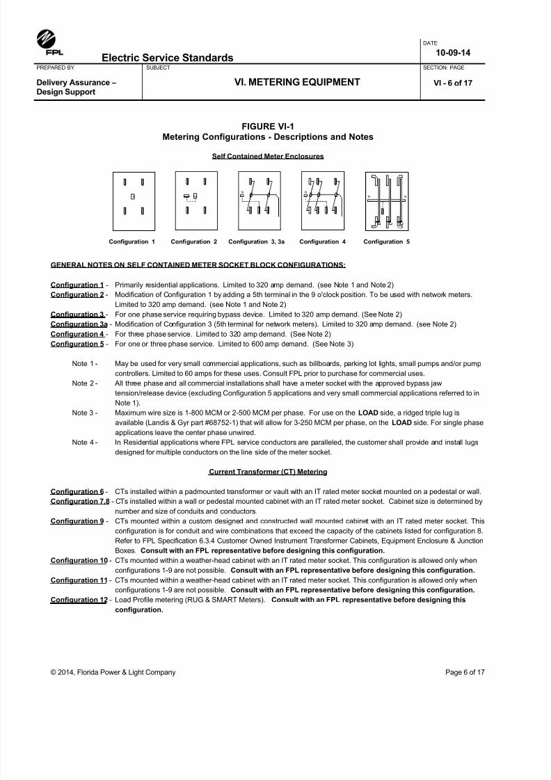
8/18/2019 electric-service-standards Florida Power Light FPL.pdf
http://slidepdf.com/reader/full/electric-service-standards-florida-power-light-fplpdf 69/118

8/18/2019 electric-service-standards Florida Power Light FPL.pdf
http://slidepdf.com/reader/full/electric-service-standards-florida-power-light-fplpdf 70/118
Electric Service Standards
DATE
10-09-14
PREPARED BY SUBJECT
VI. METERING EQUIPMENT
SECTION: PAGE
Delivery Assurance –Design Support
VI - 7 of 17
© 2014, Florida Power & Light Company Page 7 of 17
FIGURE VI-2 CT Metering Configuration 6 - CTs in Padmounted Transformer or Vault
1. IT rated meter socket provided and installed by customer: _____ 1 ph or _____ 3 ph (check one)2. Current transformers (CTs) provided and installed in padmounted transformer by FPL.3. 1-1/2” minimum rigid galvanized or Schedule 80 PVC conduit with pull string installed between meter socket and padmounted
transformer provided and installed by customer. Condulets are NOT allowed, and limited to 2 – 90 degree bends per run. Formaximum distance between transformer and meter socket, see table below.
4. Restricted to one customer per padmounted transformer. Exceptions must be approved by FPL.5. CT ratio determined by FPL.
CT Ratio Max Amps
Max Distance(feet)
Max CableLength (feet)Ratio
300:5 600 10 20
600:5 1200 40 50
1200:5 2400 40 50
2000:5 3000 40 50
FRONT OF PAD
1-1/2” minimum rigid galvanized conduitand pull string (with bushing on both ends),or 1-1/2” minimum schedule 80 PVCconduit and pull string. “Condulets” areNOT allowed. Limited to 2 – 90 degreebends per run.
Space reserved for customer conduitand cables (including CT conduit).
Space reserved for FPL conduit andcables.
IT rated meter socket(bonded by FPL).
Wall orconcretepedestal.
12” minimum cover (Galvanized)18” minimum cover (PVC)
Maximum distance(See note #3)
6’ Max5’ Min
Concrete Pad
Grade
LEGEND:
FRONT OF PAD

8/18/2019 electric-service-standards Florida Power Light FPL.pdf
http://slidepdf.com/reader/full/electric-service-standards-florida-power-light-fplpdf 71/118
Electric Service Standards
DATE
10-09-14
PREPARED BY SUBJECT
VI. METERING EQUIPMENT
SECTION: PAGE
Delivery Assurance –Design Support
VI - 8 of 17
© 2014, Florida Power & Light Company Page 8 of 17
FIGURE VI-2a
Unistrut mounting for Instrument Rated TUV meter cans (CT metering)
13
½"
13
½"
Standalone customer provided TUV instrument
rated meter can on unistrut support
Standalone customer provided TUV instrument
rated meter can on unistrut support (Load Control)
Unistrut MUST
be able to adjust
UP& DOWN
Unistrut MUST
be able to adjust
UP& DOWN
5'8" Max Height
1) Meter cans face away from the TX.
2) Bury unistrut in ground minimum 3 feet in compacted earth, or 2 feet if encased in concrete
3) When applicable, FPL provides and installs the Load Control Junction Box (LCJB)
4) Unistrut Requirements:
A. Unistrut - Per ASTM Spec. A-123 or A-153,1-5/8 x 1-5/8", 12 ga., 9/16" dia. Holes spaced 1- 7/8" apart
B. To connect the Unistrut Framing use:
3/8 x 1-¼" electrogalvanized bolts, per ASTM A164
Nut w/ spring for 3/8 dia. bolt, electrogalvanized, per ASTM A164
Flat Washer - 1" dia. for 3/8" bolt, electrogalvanized, per ASTM A164
Lock Washer - for 3/8" dia. bolt, hot-dipped galvanized, per ASTM A153
C. To attach cabinets and boxes use:
¼” x 20 electrogalvanized bolts, per ASTM A164
Nut w/ spring for ¼" dia. bolt, electrogalvanized, per ASTM A164
1- 1/2" conduit from CTs
to meter can
Conduit for meter can
ground wire - attach to
driven ground per FPL
Standards
Customer’s 1 ¼" Conduit
W/ 3 conductor wire to
switchgear
1- 1/2" conduit
from CTs to
meter can
Conduit for meter can
ground wire - attach to
driven ground per FPL
Standards
FPL LOAD
CONTROLJunction
Box
8 ½"
12”
10”
18 ½" 18 ½"
14 ½" 14 ½"
5" Space5" Space
12”
10”
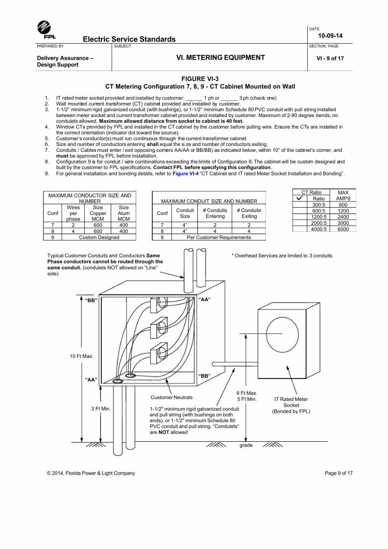
8/18/2019 electric-service-standards Florida Power Light FPL.pdf
http://slidepdf.com/reader/full/electric-service-standards-florida-power-light-fplpdf 72/118
Electric Service Standards
DATE
10-09-14
PREPARED BY SUBJECT
VI. METERING EQUIPMENT
SECTION: PAGE
Delivery Assurance –Design Support
VI - 9 of 17
© 2014, Florida Power & Light Company Page 9 of 17
FIGURE VI-3
CT Metering Configuration 7, 8, 9 - CT Cabinet Mounted on Wall
MAXIMUM CONDUCTOR SIZE ANDNUMBER MAXIMUM CONDUIT SIZE AND NUMBER
ConfWiresper
phase
SizeCopperMCM
Size AlumMCM
ConfConduit
Size# ConduitsEntering
# ConduitsExiting
7 2 600 400 7 4” 2 2
8 4 600 400 8 4” 4 4
9 Custom Designed 9 Per Customer Requirements
CT Ratio MAX AMPSRatio
300:5 600
600:5 1200
1200:5 2400
2000:5 3000
4000:5 6000
1. IT rated meter socket provided and installed by customer: ______ 1 ph or ______ 3 ph (check one)2. Wall mounted current transformer (CT) cabinet provided and installed by customer.3. 1-1/2” minimum rigid galvanized conduit (with bushings), or 1-1/2” minimum Schedule 80 PVC conduit with pull string installed
between meter socket and current transformer cabinet provided and installed by customer. Maximum of 2-90 degree bends, nocondulets allowed. Maximum allowed distance from socket to cabinet is 40 feet.
4. Window CTs provided by FPL and installed in the CT cabinet by the customer before pulling wire. Ensure the CTs are installed inthe correct orientation (indicator dot toward the source).
5. Customer’s conductor(s) must run continuous through the current transformer cabinet.6. Size and number of conductors entering shall equal the size and number of conductors exiting.7. Conduits / Cables must enter / exit opposing corners AA/AA or BB/BB) as indicated below, within 10” of the cabinet’s corner, and
must be approved by FPL before installation.8. Configuration 9 is for conduit / wire combinations exceeding the limits of Configuration 8. The cabinet will be custom designed and
built by the customer to FPL specifications. Contact FPL before specifying this configuration.
9. For general installation and bonding details, refer to Figure VI-4 “CT Cabinet and IT rated Meter Socket Installation and Bonding”.
Typical Customer Conduits and Conductors Same
Phase conductors cannot be routed through the
same conduit. (condulets NOT allowed on “Line”
side)
* Overhead Services are limited to 3 conduits
IT Rated Meter
Socket
(Bonded by FPL)
6 Ft Max.
5 Ft Min.Customer Neutrals
1-1/2" minimum rigid galvanized conduitand pull string (with bushings on bothends), or 1-1/2" minimum Schedule 80PVC conduit and pull string. “Condulets”are NOT allowed
10 Ft Max.
3 Ft Min.
grade
“AA”
“AA”“BB”
“BB”

8/18/2019 electric-service-standards Florida Power Light FPL.pdf
http://slidepdf.com/reader/full/electric-service-standards-florida-power-light-fplpdf 73/118
Electric Service Standards
DATE
10-09-14
PREPARED BY SUBJECT
VI. METERING EQUIPMENT
SECTION: PAGE
Delivery Assurance –Design Support
VI - 10 of 17
© 2014, Florida Power & Light Company Page 10 of 17
FIGURE VI-4
CT Cabinet and IT Rated Meter Socket - Installation and Bonding
FPL Will:
1. Furnish and install the IT rated meter socket bonding wire.
2. Furnish and install the instrument transformers, the wiring
from the transformer secondary to the meter, and set the
meter.
The Customer Will:
1. Furnish and install the service entrance conduit, conductors, and
equipment, including grounds.
2. Furnish and install the IT rated meter socket, current transformer cabinet
(when required), and equipment enclosures (when required).
3. Furnish and install any conduit necessary to connect the cabinets and
sockets including a pull string.
4. Mount cabinet with sealing ears at bottom.
5. Fasten cabinet and meter socket to masonry walls with toggle screws or
expansion shields (no plastic plugs or impact tools).
6. When cabinet is installed in exposed locations, install conduits entering
top of cabinet with approved watertight connectors.7. Installations must conform to local code requirements.
8. Furnish and install bonding jumpers from service disconnect equipment
to current transformer cabinet.
NOTES:
1. All IT rated meter sockets and current transformer cabinets to be bonded with #12C bonding jumper (green with white stripe) by FPL.
Customer’s service disconnect equipment to be bonded to current transformer cabinet with #12C bonding jumper (green with white stripe)
by the customer.
2. If the IT rated meter socket or transformer cabinet is mounted on a utility pole, then it is to be grounded per FPL distribution standards.
3. Customer’s conductor(s) must be continuous through the transformer cabinet.
Customer’s
Service
Neutral
Transformer Cabinet
Green and White
Bonding Jumper
(by FPL)
IT Rated
Meter Socket
Bonding Jumper
(by FPL)See Note 2
Customer’s
Service
Neutral
1-1/2” rigid galvanized conduit and pull string (with bushing on both
ends), or 1-1/2” Schedule 80 PVC conduit and pull string.
“Condulets” are NOT allowed.
Customer’s
Main Line
Switch
Green and White
Bonding Jumper(by Customer)

8/18/2019 electric-service-standards Florida Power Light FPL.pdf
http://slidepdf.com/reader/full/electric-service-standards-florida-power-light-fplpdf 74/118
Electric Service Standards
DATE
10-09-14
PREPARED BY SUBJECT
VI. METERING EQUIPMENT
SECTION: PAGE
Delivery Assurance –Design Support
VI - 11 of 17
© 2014, Florida Power & Light Company Page 11 of 17
FIGURE VI-5
CT Metering Configuration 10 - CTs in Weatherhead Cabinet
USED FOR MAINTENANCE ONLY (Not intended for new installations)
1. IT rated meter socket provided and installed by customer: ______ 1 ph or ______ 3 ph (check one).2. Weatherhead transformer cabinet provided and installed by customer.3. 1-1/2” minimum rigid galvanized conduit (with bushings) or 1-1/2” minimum Schedule 80 PVC, with pull string installed between meter
socket and current transformer cabinet provide and installed by customer. Maximum allowed distance between socket and cabinet is40 feet.
4. Customer to provide and install watertight “Myers type” conduit connector when conduit enters top of IT rated meter socket.5. Window CTs provided and installed in transformer cabinet by FPL after cabinet is mounted by customer.6. FPL service cable will pass through CTs unless otherwise approved by FPL.7. This configuration allowed ONLY when no other configuration is possible, or practical, and must be approved by FPL. Contact FPL
before specifying this configuration. 8. For general installation and bonding details, refer to Figure VI-4 “CT Cabinet and IT rated Meter Socket Installation and Bonding”.
CT Ratio MAX AMPSRatio
300:5 600
600:5 1200
1200:5 2400
FPL Service Cable:Max Parallel 556 QPX
NeutralConnector
Customer’s Weatherhead
9” Min.36” Max.
WindowCTs
Hi-leg (when 3phase “Delta”)
ServiceConnections
(by FPL)
20’ Max.
Min. Heightper Code
6’ Max.5’ Min.
grade
WatertightConnector
IT rated meter socket(Bonded by FPL)
1-1/2” rigid galvanized conduit and pull string
(with bushing on both ends), or 1-1/2”
Schedule 80 PVC conduit and pull string.
“Condulets” are NOT allowed.

8/18/2019 electric-service-standards Florida Power Light FPL.pdf
http://slidepdf.com/reader/full/electric-service-standards-florida-power-light-fplpdf 75/118
Electric Service Standards
DATE
10-09-14
PREPARED BY SUBJECT
VI. METERING EQUIPMENT
SECTION: PAGE
Delivery Assurance –Design Support
VI - 12 of 17
© 2014, Florida Power & Light Company Page 12 of 17
FIGURE VI-6
CT Metering Configuration 11 - CTs in Padmounted Primary Metering Cabinet
1. IT rated meter socket provided and installed by customer: ______ 1 ph or ______ 3 ph (check one).2. Padmounted primary metering cabinet and concrete pad provided or purchased and installed by customer.3. 1-1/2” minimum rigid galvanized conduit (with bushings) or 1-1/2” minimum Schedule 80 PVC, with pull string installed between
meter socket and current transformer cabinet provide and installed by customer. Maximum of 2-90 degree bends allowed.Maximum allowed distance between socket and cabinet is 40 feet.
4. Primary (4 KV, 13 KV, 23KV) current and voltage transformers provided and installed by FPL.5. This configuration’s application is limited and requires close coordination. Consult with an FPL representative before designing
this configuration.
1-1/2” minimum rigid galvanized conduit and pullstring (with bushing on both ends), or 1-1/2”minimum Schedule 80 PVC conduit and pull
string. “Condulets” are NOT allowed.
IT rated meter socket
(Bonded by FPL)
Optional meter can
location
Customer provided orpurchased Padmounted
Primary Metering Cabinet
Conduit poured inslab or thru window
6’ Max.5’ Min.
12” Min Cover (Galv.)18” Min Cover (PVC)
grade
Maximum distanceallowed is 40 feet
Wall or Pedestal
Rear doors
CTs PTs
Front doors
SIDE VIEW
FRONT VIEW

8/18/2019 electric-service-standards Florida Power Light FPL.pdf
http://slidepdf.com/reader/full/electric-service-standards-florida-power-light-fplpdf 76/118
Electric Service Standards
DATE
10-09-14
PREPARED BY SUBJECT
VI. METERING EQUIPMENT
SECTION: PAGE
Delivery Assurance –Design Support
VI - 13 of 17
© 2014, Florida Power & Light Company Page 13 of 17
FIGURE VI-6a CT Metering Configuration 11 – Renewable Generation ONLY
1. SJB cabinet provided by FPL, installed by customer. Fasten cabinet to masonry walls with toggle screws or expansion shields (noplastic anchors or impact tools).
2. Padmounted primary metering cabinet and concrete pad provided or purchased and installed by customer.3. 1-1/2” minimum rigid galvanized conduit (with bushings) or 1-1/2” minimum Schedule 80 PVC, with pull string installed between
meter socket and current transformer cabinet provide and installed by customer. Maximum of 2-90 degree bends allowed.Maximum allowed distance between socket and cabinet is 6 feet.
4. Primary (4 KV, 13 KV, 23KV) current and voltage transformers provided and installed by FPL.5. This configuration’s application is limited and requires close coordination. Consult with an FPL representative before designing
this configuration.
1-1/2” minimum rigid galvanized conduit and pullstring (with bushing on both ends), or 1-1/2”minimum Schedule 80 PVC conduit and pull
string. “Condulets” are NOT allowed.
FPL provided PadmountedPrimary Metering Cabinet
Conduit poured inslab or thru window
6’ Max.5’ Min.
12” Min Cover (Galv.)18” Min Cover (PVC)
grade
Maximum distanceallowed is 6 feet
Wall or Pedestal
Rear doors
CTs PTs
Front doors
SIDE VIEW
FRONT VIEW
SJB cabinet (36” X 36” X 24”)
(Bonded by FPL)
If applicable, existing IT ratedmeter can to be glass coveredor removed by FPL meter shop
1-1/2” metering conduit

8/18/2019 electric-service-standards Florida Power Light FPL.pdf
http://slidepdf.com/reader/full/electric-service-standards-florida-power-light-fplpdf 77/118
Electric Service Standards
DATE
10-09-14
PREPARED BY SUBJECT
VI. METERING EQUIPMENT
SECTION: PAGE
Delivery Assurance –Design Support
VI - 14 of 17
© 2014, Florida Power & Light Company Page 14 of 17
FIGURE VI-7
CT Metering Configuration 12 – Load Profile Metering
1. IT rated meter socket provided and installed by customer: ______ 1 ph or ______ 3 ph (check one).2. Customer to provide metering equipment cabinet with 1-1/2” minimum rigid galvanized conduit (with bushings) or 1-1/2” minimum
Schedule 80 PVC, with pull string installed, and utility cans for interface with phone line and energy management system (ifrequired).
3. Maximum distance to CTs: 10 feet for 300:5 CTs (Max. Cable length 20 feet) or 40 feet for 600:5 and larger CTs (Max. cable length50 feet).
4. Consult with an FPL representative before designing this configuration. Multi-metered circuits may require equipmentother than shown.
Number ofmeters
Equipment Cabinet Old FPLdesignationSize H x W x D
2 – 6 Medium 28 x 30 x 14 SJB – 28
7 – 9 Large 36 x 36 x 14 SJB – C
1-1/2” minimum rigidgalvanized conduit and pullstring (with bushing on both
ends), or 1-1/2” minimumSchedule 80 PVC conduit and
pull string. “Condulets” are NOT allowed. See note #3 for
maximum distances to CTs.
IT rated meter sockets(one per set of CTs)
(Bonded by FPL)
SJB EquipmentCabinet only requiredin Multi-channel Load
Profile installations(one per installation)
(Bonded by FPL)
3/4”
Conduit
Customer to install and connect RJ11C jack in telephone jack box (UTB)
Optional LCJB (LoadControl Junction Box)
and conduit to customerload control equipment
and printer (ifapplicable). The LCJB(M&S #420-07000-7) is
supplied by FPL.
36” Max.
30” Min.
grade
Optional UTB and 3/4”conduit to customer’senergy managementsystem (if applicable).
Customer to install 2-pairtelephone line in 3/4”conduit to telephone
connection.
All conduits are to have a pullstring installed.

8/18/2019 electric-service-standards Florida Power Light FPL.pdf
http://slidepdf.com/reader/full/electric-service-standards-florida-power-light-fplpdf 78/118
Electric Service Standards
DATE
10-09-14
PREPARED BY SUBJECT
VI. METERING EQUIPMENT
SECTION: PAGE
Delivery Assurance –Design Support
VI - 15 of 17
© 2014, Florida Power & Light Company Page 15 of 17
FIGURE VI-8 Identification of Multiple Meter Sockets
Customer to mark meter socket and switch covers with paint or other permanent durable marker to identify
premises served. Markings should also be put inside meter socket (to prevent confusion if covers areinterchanged before service is connected). If living units have different house numbers, these should be shown inplace of apartment numbers. IT rated meter sockets (not illustrated) should be marked similarly.
The Electrical Contractor shall provide FPL a meter layout drawing.
APT. 1 APT. 2 APT. 3 APT. 4 APT. 5
APT. 1 APT. 2 APT. 3 APT. 4 APT. 5
CUSTOMER’SSWITCH
CUSTOMER’SSWITCH
CUSTOMER’SSWITCH
CUSTOMER’SSWITCH
CUSTOMER’SSWITCH
Customer’s serviceentrance conduit

8/18/2019 electric-service-standards Florida Power Light FPL.pdf
http://slidepdf.com/reader/full/electric-service-standards-florida-power-light-fplpdf 79/118
Electric Service Standards
DATE
10-09-14
PREPARED BY SUBJECT
VI. METERING EQUIPMENT
SECTION: PAGE
Delivery Assurance –Design Support
VI - 16 of 17
© 2014, Florida Power & Light Company Page 16 of 17
FIGURE VI-9
Meter Enclosure Installations in Flood Zones
Note: When elevation of the meter enclosure is required by the authority having jurisdiction, the permanent installation ofdeck/platform and stairs shall be installed and provided by customer prior to energizing the facility.
Meter enclosureabove flood plain
Min 36” width
Max 6’Min 5’
PermanentStairs
Porch, deck,or platform60” Min indepth
2” conduit bycustomer
Flood Plane
Variesdepending
on area
Min 36” width
Min 60” depth

8/18/2019 electric-service-standards Florida Power Light FPL.pdf
http://slidepdf.com/reader/full/electric-service-standards-florida-power-light-fplpdf 80/118
Electric Service Standards
DATE
10-09-14
PREPARED BY SUBJECT
VI. METERING EQUIPMENT
SECTION: PAGE
Delivery Assurance –Design Support
VI - 17 of 17
© 2014, Florida Power & Light Company Page 17 of 17
FIGURE VI-10Typical Bus Stub Terminations in Transformer Vaults

8/18/2019 electric-service-standards Florida Power Light FPL.pdf
http://slidepdf.com/reader/full/electric-service-standards-florida-power-light-fplpdf 81/118
The attached list of self-contained meter sockets and enclosures has been approved for use in the service areas
served by the utilities of the Meter Equipment Group. Approval is based on the unit's compliance with the MEGspecifications, particularly U.L. listing, sealing requirements, bypass characteristics, and certain operational concerns.The MEG makes no claims regarding nameplate ratings or load side attachments beyond the sealed portion of themeter socket. We recommend that all units be used as intended by the manufacturer. All additional data issupplied for informational purposes only.
NOTES:
A. All commercial or three phase applications require a unit with an approved bypass device.(Configuration 3, 4 or 5)
B. All sockets are listed as their maximum socket amperage. 320/400 Amp enclosures are listed as 400 Ampmaximum and 480/600 Amp enclosures are listed as 600 Amp maximum.
C. Aluminum enclosures are recommended in salt spray areas.
D. Sealing rings (ring-type sockets) along with all lugs/connectors (line and load side) are consideredto be part of the meter enclosure. The customer/contractor is thereby responsible for furnishing theseitems. Please contact your utility representative to determine the proper size lugs/connectors. Thesealing ring must be a captive-screw type equivalent to ABB #01L0028G02, Milbank MR-4/A3068,Landis & Gyr #9738-8002, or Ekstrom 10-9090.
E. The "configuration" refers to the various meter connecting arrangements used to accommodate the utilitymeter. These configurations are described below:
SELF CONTAINED
CONFIGURATIONS DESCRIPTION & TYPICAL APPLICATION
1 Residential - 4 Terminal Socket, Single Phase, 3 Wire2 Residential - 5 Terminal Socket, Network, 3 Wire3 Residential/Commercial - 4 Terminal Socket (w/Bypass), Single Phase, 3 Wire3a Residential/Commercial - 5 Terminal Socket (w/Bypass), Network, 3 Wire4 Commercial - 7 Terminal Socket (w/Bypass), Three Phase, 4 Wire*5 Residential/Commercial – K7 Base (w/Bypass), Single Phase (FPL Only),
Three Phase or Network, 3 or 4 Wire
*K7 Three Phase K-Base applications are ONLY allowed at FPL(GULF, DUKE, and TECO do not al low any K-base instal lat ions)
Enclosure List:Revised
1/22/2015
Approved Meter Equipment
Participants:
Page 1 of 14
FPL - Florida Power Light DUKE Energy TECO - Tampa Electric GULF - Gulf Power
© 2015, Meter Equipment Group

8/18/2019 electric-service-standards Florida Power Light FPL.pdf
http://slidepdf.com/reader/full/electric-service-standards-florida-power-light-fplpdf 82/118

8/18/2019 electric-service-standards Florida Power Light FPL.pdf
http://slidepdf.com/reader/full/electric-service-standards-florida-power-light-fplpdf 83/118
Manufacturer Catalog Number Amps Phase Service Pos Term Bypass Config
Approved Metering Equipment Enclosure List
Participants: FPL, GULF, DUKE, TECO
Revised
1/22/2015
Durham UT-H7330U-FL400 3 Ov/Un 1 7 Y 4
Eaton B-Line ECCB10L25A3xx1F (where xx=GR, AL, SS)100 1 OH/UG 1 5 Y
Eaton B-Line ECCB10L27A3xx1F (where xx=GR, AL, SS)100 3 OH/UG 1 7 Y 4
Eaton B-Line ENCB10L25A3xx1F (where xx=GR, AL, SS)100 1 OH/UG 1 5 N
Eaton B-Line HEC10432Cxx1F (where xx=GR, AL, SS)100 1 OH/UG 2 4 Y 3
Eaton B-Line HEC10433Cxx1F (where xx=GR, AL, SS)100 1 OH/UG 3 4 Y 3
Eaton B-Line HEN10432Lxx1F (where xx=GR, AL, SS)100 1 OH/UG 2 4 N 3
Eaton B-Line HEN10433Lxx1F (where xx=GR, AL, SS)100 1 OH/UG 3 4 N 3
Eaton B-Line HEN10434Lxx1F (where xx=GR, AL, SS)100 1 OH/UG 4 4 N 3
Eaton B-Line HEN10435Lxx1F (where xx=GR, AL, SS)100 1 OH/UG 5 4 N 3
Eaton B-Line HEN10436Lxx1F (where xx=GR, AL, SS)100 1 OH/UG 6 4 N 3
Eaton B-Line EC12L53xx1F (where xx=GR, AL, SS)125 1 OH/UG 1 5 Y
Eaton B-Line EN12L41xx1F (where xx=GR, AL, SS)125 1 OH 1 4 N 1
Eaton B-Line EN12L42xx1F (where xx=GR, AL, SS)125 1 UG 1 4 N 1
Eaton B-Line EN12L43xx1F (where xx=GR, AL, SS)125 1 OH/UG 1 4 N 1
Eaton B-Line EN12L51xx1F (where xx=GR, AL, SS)125 1 OH 1 5 N 2
Eaton B-Line EN12L52xx1F (where xx=GR, AL, SS)125 1 UG 1 5 N 2
Eaton B-Line EN12L53xx1F (where xx=GR, AL, SS)125 1 OH/UG 1 5 N 2
Eaton B-Line VENMP12432Lxx1F (where xx=GR, AL, SS)125 1 OH/UG 2 4 N 3
Eaton B-Line VENMP12433Lxx1F (where xx=GR, AL, SS)125 1 OH/UG 3 4 N 3
Eaton B-Line VENMP12434Cxx1F (where xx=GR, AL, SS)125 1 OH/UG 4 4 N 3
Eaton B-Line VENMP12435Cxx1F (where xx=GR, AL, SS)125 1 OH/UG 5 4 N 3
Eaton B-Line VENMP12436Cxx1F (where xx=GR, AL, SS)125 1 OH/UG 6 4 N 3
Eaton B-Line ENCB15L25A3xx1F (where xx=GR, AL, SS)150 1 OH/UG 1 5 N
Eaton B-Line EL20L53xx1F (where xx=GR, AL, SS)200 1 OH/UG 1 5 Y
Eaton B-Line EL20L73xx1F (where xx=GR, AL, SS)200 3 OH/UG 1 7 Y 4
Eaton B-Line ELCB20L25A3xx1F (where xx=GR, AL, SS)200 1 OH/UG 1 5 Y
Eaton B-Line ELCB20L27A3xx1F (where xx=GR, AL, SS)200 3 OH/UG 1 7 Y 4
Eaton B-Line EN20L41xx1F (where xx=GR, AL, SS)200 1 OH 1 4 N 1
Eaton B-Line EN20L42xx1F (where xx=GR, AL, SS)200 1 UG 1 4 N 1
Eaton B-Line EN20L43xx1F (where xx=GR, AL, SS)200 1 OH/UG 1 4 N 1
Eaton B-Line EN20L51xx1F (where xx=GR, AL, SS)200 1 OH 1 5 N 2
Eaton B-Line EN20L52xx1F (where xx=GR, AL, SS)200 1 UG 1 5 N 2
Eaton B-Line EN20L53xx1F (where xx=GR, AL, SS)200 1 OH/UG 1 5 N 2
Eaton B-Line ENCB20L25A3xx1F (where xx=GR, AL, SS)200 1 OH/UG 1 5 N
Eaton B-Line HEL20432Cxx1F (where xx=GR, AL, SS)200 1 OH/UG 2 4 Y 3
Eaton B-Line HEL20433Cxx1F (where xx=GR, AL, SS)200 1 OH/UG 3 4 Y 3
Eaton B-Line HEL20434Cxx1F (where xx=GR, AL, SS)200 1 OH/UG 4 4 Y 3
Eaton B-Line HEL20435Cxx1F (where xx=GR, AL, SS)200 1 OH/UG 5 4 Y 3
Page 3 of 14
FPL - Florida Power Light DUKE Energy TECO - Tampa Electric GULF - Gulf Power
© 2015, Meter Equipment Group

8/18/2019 electric-service-standards Florida Power Light FPL.pdf
http://slidepdf.com/reader/full/electric-service-standards-florida-power-light-fplpdf 84/118
Manufacturer Catalog Number Amps Phase Service Pos Term Bypass Config
Approved Metering Equipment Enclosure List
Participants: FPL, GULF, DUKE, TECO
Revised
1/22/2015
Eaton B-Line HEL20436Cxx1F (where xx=GR, AL, SS)200 1 OH/UG 6 4 Y 3
Eaton B-Line HEL20732Cxx1F (where xx=GR, AL, SS)200 3 OH/UG 2 7 Y 4
Eaton B-Line HEL20733Cxx1F (where xx=GR, AL, SS)200 3 OH/UG 3 7 Y 4
Eaton B-Line HEL20734Cxx1F (where xx=GR, AL, SS)200 3 OH/UG 4 7 Y 4
Eaton B-Line HEL20735Cxx1F (where xx=GR, AL, SS)200 3 OH/UG 5 7 Y 4
Eaton B-Line HEL20736Cxx1F (where xx=GR, AL, SS)200 3 OH/UG 6 7 Y 4
Eaton B-Line VENMP20432Lxx1F (where xx=GR, AL, SS)200 1 OH/UG 2 4 N 3
Eaton B-Line VENMP20433Lxx1F (where xx=GR, AL, SS)200 1 OH/UG 3 4 N 3
Eaton B-Line VENMP20434Cxx1F (where xx=GR, AL, SS)200 1 OH/UG 4 4 N 3
Eaton B-Line VENMP20435Cxx1F (where xx=GR, AL, SS)200 1 OH/UG 5 4 N 3
Eaton B-Line VENMP20436Cxx1F (where xx=GR, AL, SS)200 1 OH/UG 6 4 N 3
Eaton B-Line EL32T53xx1F (where xx=GR, AL, SS)400 1 OH/UG 1 5 Y
Eaton B-Line EL32T56xx1F (where xx=GR, AL, SS)400 1 OH/UG 1 5 Y
Eaton B-Line EL32T75xx1F (where xx=GR, AL, SS)400 3 OH/UG 1 7 Y 4
Eaton B-Line EL32T76xx1F (where xx=GR, AL, SS)400 3 OH/UG 1 7 Y 4
Eaton B-Line ELCB32C24A5xx1F (where xx=GR, AL, SS)400 1 OH/UG 1 5 Y
Eaton-Cutler Hammer UTZ-6R1131C-FLCH100 1 Ov/Un 6 4/5 N 1,2
Eaton-Cutler Hammer UTZ-xR1121C-FLCH (where x=2-5)100 1 Ov/Un 2-5 4/5 N 1,2
Eaton-Cutler Hammer CHR (POWER OUTLET PANEL)125 1 Ov/Un 1 4 N 1,2
Eaton-Cutler Hammer CMB24L125BTS FLCH125 1 Ov/Un 1 4/5 N 1,2
Eaton-Cutler Hammer MB24L125BTS FLCH125 1 Ov/Un 1 4/5 N 1,2
Eaton-Cutler Hammer UATZ-RS101C-FLCH125 1 Ov/Un 1 4/5 N 1,2 Al
Eaton-Cutler Hammer UTZ-RS101C-FLCH125 1 Ov/Un 1 4/5 N 1,2
Eaton-Cutler Hammer CMB88B150BTS FLCH150 1 Ov/Un 1 4 N 1,2
Eaton-Cutler Hammer CMBB150BTS FLCH150 1 Ov/Un 1 4/5 N 1,2
Eaton-Cutler Hammer MB816B150BTS FLCH150 1 Ov/Un 1 4 N 1,2
Eaton-Cutler Hammer MBB150BTS FLCH150 1 Ov/Un 1 4 N 1,2
Eaton-Cutler Hammer MBT48B150BTS150 1 Ov/Un 1 4/5 N 1,2
Eaton-Cutler Hammer CMB1212B200BTS FLCH200 1 Ov/Un 1 4/5 N 1
Eaton-Cutler Hammer CMB1212L200BTS200 1 Ov/Un 1 4 N 1,2
Eaton-Cutler Hammer CMB1212P200BTS FLCH200 1 Ov/Un 1 4 N 1,2
Eaton-Cutler Hammer CMB4242B200BTS FLCH200 1 Ov/Un 1 4 N 1,2
Eaton-Cutler Hammer CMB88B200BTS FLCH200 1 Ov/Un 1 4 N 1,2
Eaton-Cutler Hammer CMBB200BTS FLCH200 1 Ov/Un 1 4 N 1,2
Eaton-Cutler Hammer CMBP200BTS FLCH200 1 Ov/Un 1 4 N 1,2
Eaton-Cutler Hammer MB1212L200BTS200 1 Ov/Un 1 4/5 N 1,2
Eaton-Cutler Hammer MB1212L200BTSA200 1 Ov/Ln 1 4/5 N 1,2 Al
Eaton-Cutler Hammer MB2040B200BTS FLCH200 1 Ov/Un 1 4 N 1,2
Eaton-Cutler Hammer MB2040P200BTS FLCH200 1 Ov/Un 1 4/5 N 1
Page 4 of 14
FPL - Florida Power Light DUKE Energy TECO - Tampa Electric GULF - Gulf Power
© 2015, Meter Equipment Group
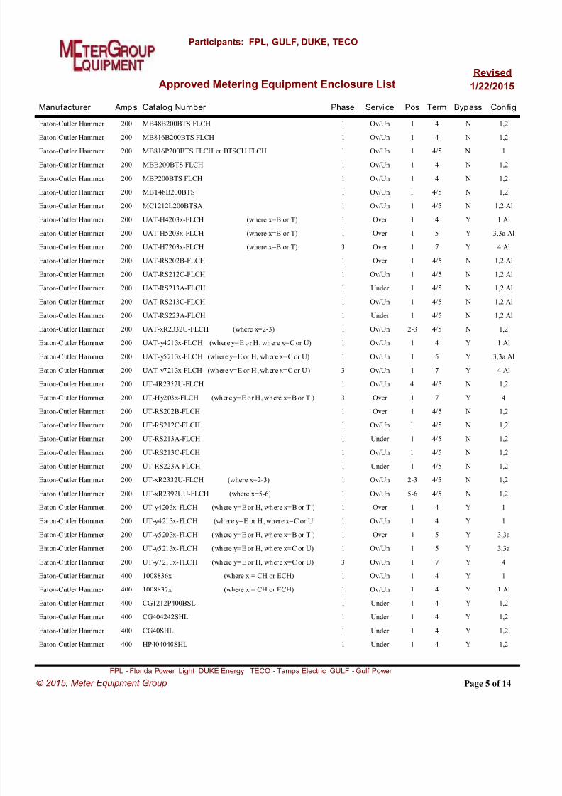
8/18/2019 electric-service-standards Florida Power Light FPL.pdf
http://slidepdf.com/reader/full/electric-service-standards-florida-power-light-fplpdf 85/118
Manufacturer Catalog Number Amps Phase Service Pos Term Bypass Config
Approved Metering Equipment Enclosure List
Participants: FPL, GULF, DUKE, TECO
Revised
1/22/2015
Eaton-Cutler Hammer MB48B200BTS FLCH200 1 Ov/Un 1 4 N 1,2
Eaton-Cutler Hammer MB816B200BTS FLCH200 1 Ov/Un 1 4 N 1,2
Eaton-Cutler Hammer MB816P200BTS FLCH or BTSCU FLCH200 1 Ov/Un 1 4/5 N 1
Eaton-Cutler Hammer MBB200BTS FLCH200 1 Ov/Un 1 4 N 1,2
Eaton-Cutler Hammer MBP200BTS FLCH200 1 Ov/Un 1 4 N 1,2
Eaton-Cutler Hammer MBT48B200BTS200 1 Ov/Un 1 4/5 N 1,2
Eaton-Cutler Hammer MC1212L200BTSA200 1 Ov/Un 1 4/5 N 1,2 Al
Eaton-Cutler Hammer UAT-H4203x-FLCH (where x=B or T)200 1 Over 1 4 Y 1 Al
Eaton-Cutler Hammer UAT-H5203x-FLCH (where x=B or T)200 1 Over 1 5 Y 3,3a Al
Eaton-Cutler Hammer UAT-H7203x-FLCH (where x=B or T)200 3 Over 1 7 Y 4 Al
Eaton-Cutler Hammer UAT-RS202B-FLCH200 1 Over 1 4/5 N 1,2 Al
Eaton-Cutler Hammer UAT-RS212C-FLCH200 1 Ov/Un 1 4/5 N 1,2 Al
Eaton-Cutler Hammer UAT-RS213A-FLCH200 1 Under 1 4/5 N 1,2 Al
Eaton-Cutler Hammer UAT-RS213C-FLCH200 1 Ov/Un 1 4/5 N 1,2 Al
Eaton-Cutler Hammer UAT-RS223A-FLCH200 1 Under 1 4/5 N 1,2 Al
Eaton-Cutler Hammer UAT-xR2332U-FLCH (where x=2-3)200 1 Ov/Un 2-3 4/5 N 1,2
Eaton-Cutler Hammer UAT-y4213x-FLCH (where y=E or H, where x=C or U)200 1 Ov/Un 1 4 Y 1 Al
Eaton-Cutler Hammer UAT-y5213x-FLCH (where y=E or H, where x=C or U)200 1 Ov/Un 1 5 Y 3,3a Al
Eaton-Cutler Hammer UAT-y7213x-FLCH (where y=E or H, where x=C or U)200 3 Ov/Un 1 7 Y 4 Al
Eaton-Cutler Hammer UT-4R2352U-FLCH200 1 Ov/Un 4 4/5 N 1,2
Eaton-Cutler Hammer UT-Hy203x-FLCH (where y=E or H, where x=B or T )200 3 Over 1 7 Y 4
Eaton-Cutler Hammer UT-RS202B-FLCH200 1 Over 1 4/5 N 1,2
Eaton-Cutler Hammer UT-RS212C-FLCH200 1 Ov/Un 1 4/5 N 1,2
Eaton-Cutler Hammer UT-RS213A-FLCH200 1 Under 1 4/5 N 1,2
Eaton-Cutler Hammer UT-RS213C-FLCH200 1 Ov/Un 1 4/5 N 1,2
Eaton-Cutler Hammer UT-RS223A-FLCH200 1 Under 1 4/5 N 1,2
Eaton-Cutler Hammer UT-xR2332U-FLCH (where x=2-3)200 1 Ov/Un 2-3 4/5 N 1,2
Eaton-Cutler Hammer UT-xR2392UU-FLCH (where x=5-6)200 1 Ov/Un 5-6 4/5 N 1,2
Eaton-Cutler Hammer UT-y4203x-FLCH (where y=E or H, where x=B or T )200 1 Over 1 4 Y 1
Eaton-Cutler Hammer UT-y4213x-FLCH (where y=E or H, where x=C or U200 1 Ov/Un 1 4 Y 1
Eaton-Cutler Hammer UT-y5203x-FLCH (where y=E or H, where x=B or T )200 1 Over 1 5 Y 3,3a
Eaton-Cutler Hammer UT-y5213x-FLCH (where y=E or H, where x=C or U)200 1 Ov/Un 1 5 Y 3,3a
Eaton-Cutler Hammer UT-y7213x-FLCH (where y=E or H, where x=C or U)200 3 Ov/Un 1 7 Y 4
Eaton-Cutler Hammer 1008836x (where x = CH or ECH)400 1 Ov/Un 1 4 Y 1
Eaton-Cutler Hammer 1008837x (where x = CH or ECH)400 1 Ov/Un 1 4 Y 1 Al
Eaton-Cutler Hammer CG1212P400BSL400 1 Under 1 4 Y 1,2
Eaton-Cutler Hammer CG404242SHL400 1 Under 1 4 Y 1,2
Eaton-Cutler Hammer CG40SHL400 1 Under 1 4 Y 1,2
Eaton-Cutler Hammer HP404040SHL400 1 Under 1 4 Y 1,2
Page 5 of 14
FPL - Florida Power Light DUKE Energy TECO - Tampa Electric GULF - Gulf Power
© 2015, Meter Equipment Group

8/18/2019 electric-service-standards Florida Power Light FPL.pdf
http://slidepdf.com/reader/full/electric-service-standards-florida-power-light-fplpdf 86/118
Manufacturer Catalog Number Amps Phase Service Pos Term Bypass Config
Approved Metering Equipment Enclosure List
Participants: FPL, GULF, DUKE, TECO
Revised
1/22/2015
Eaton-Cutler Hammer HP40SHL400 1 Under 1 4 Y 1,2
Eaton-Cutler Hammer HP816Px00BSL (where x = 3 or 4)400 1 Under 1 4 Y 1,2
Eaton-Cutler Hammer UATH4330TFLCH400 1 Ov/Un 1 4 Y 1 Al
Eaton-Cutler Hammer UAT-y4300T-FLCH (where y=E or H)400 1 Over 1 4 Y 1 Al
Eaton-Cutler Hammer UAT-y5300T-FLCH (where y=E or H)400 1 Over 1 5 Y 3,3a Al
Eaton-Cutler Hammer UAT-y5330U-FLCH (where y=E or H)400 1 Ov/Un 1 5 Y 3,3a Al
Eaton-Cutler Hammer UAT-y7300T-FLCH (where y=E or H)400 3 Over 1 7 Y 4 Al
Eaton-Cutler Hammer UAT-y7330U-FLCH (where y=E or H)400 3 Ov/Un 1 7 Y 4 Al
Eaton-Cutler Hammer UTH4330TFLCH400 1 Ov/Un 1 4 Y 1
Eaton-Cutler Hammer UT-y4300T-FLCH (where y=E or H)400 1 Over 1 4 Y 1
Eaton-Cutler Hammer UT-y5300T-FLCH (where y=E or H)400 1 Over 1 5 Y 3,3a
Eaton-Cutler Hammer UT-y5330U-FLCH (where y=E or H)400 1 Ov/Un 1 5 Y 3,3a
Eaton-Cutler Hammer UT-y7300T-FLCH (where y=E or H)400 3 Over 1 7 Y 4
Eaton-Cutler Hammer UT-y7330U-FLCH (where y=E or H)400 3 Ov/Un 1 7 Y 4
Eaton-Cutler Hammer CH9526K7 (Requires Ridged Lugs) FPL ONLY600 3 Ov/Un 1 7 Y 5
Eaton-Cutler Hammer CH9527K7 (Requires Ridged Lugs) FPL ONLY600 3 Ov/Un 1 7 Y 5 Al
Elec.Prod. RVPD-xxxx-FPL100 1 Under 2 4 N 1
Elec.Prod. RVP-xxxx-FPL100 1 Under 1 4 N 1
Elec.Prod. MHPD-xxxx-FPL200 1 Under 2 4 N 1
Elec.Prod. MHP-xxxx-FPL200 1 Under 1 4 N 1
Emerson MESBGFXLW11FBZ1125 1 Under 1 5 Y 3a
Emerson MESBGFXLW11FBZ1P125 1 Under 1 5 Y 3a
Emerson MESBGFXLW11KBZ1125 1 Under 1 5 Y 3a
Emerson MESBGFXLW11KBZ1P125 1 Under 1 5 Y 3a
Emerson MESBAATLW11FBZ1200 1 Under 1 5 Y 3a
Emerson MESBAATLW11FBZ1P200 1 Under 1 5 Y 3a
Emerson MESBAATLW11KBZ1200 1 Under 1 5 Y 3a
Emerson MESBAATLW11KBZ1P200 1 Under 1 5 Y 3a
General Electric TSDR830USCU(2) 150 1 Under 1 4/5 Y 1,2
General Electric TM10RMCFMG100 1 Ov/Un 1 4 N 1
General Electric TM12RMCFMG125 1 Ov/Un 1 4 N 1
General Electric TM15RMCFMG150 1 Ov/Un 1 4 N 1
General Electric TSMF415CSFL150 1 Ov/Un 1 4/5 N 1,2
General Electric TSMF815CSFL150 1 Ov/Un 1 4/5 N 1,2
General Electric TSMR415CSFLFMG150 1 Ov/Un 1 4 N 1
General Electric TSMR815CSFLFMG150 1 Ov/Un 1 4 N 1
General Electric TM20RMCFMG200 1 Ov/Un 1 4 N 1
General Electric TMPR312x22R (where x=1-4)200 3 Ov/Un 1-4 7 Y 4
General Electric TSLR1220FSAL200 1 Ov/Un 1 4 N 1, Al
Page 6 of 14
FPL - Florida Power Light DUKE Energy TECO - Tampa Electric GULF - Gulf Power
© 2015, Meter Equipment Group
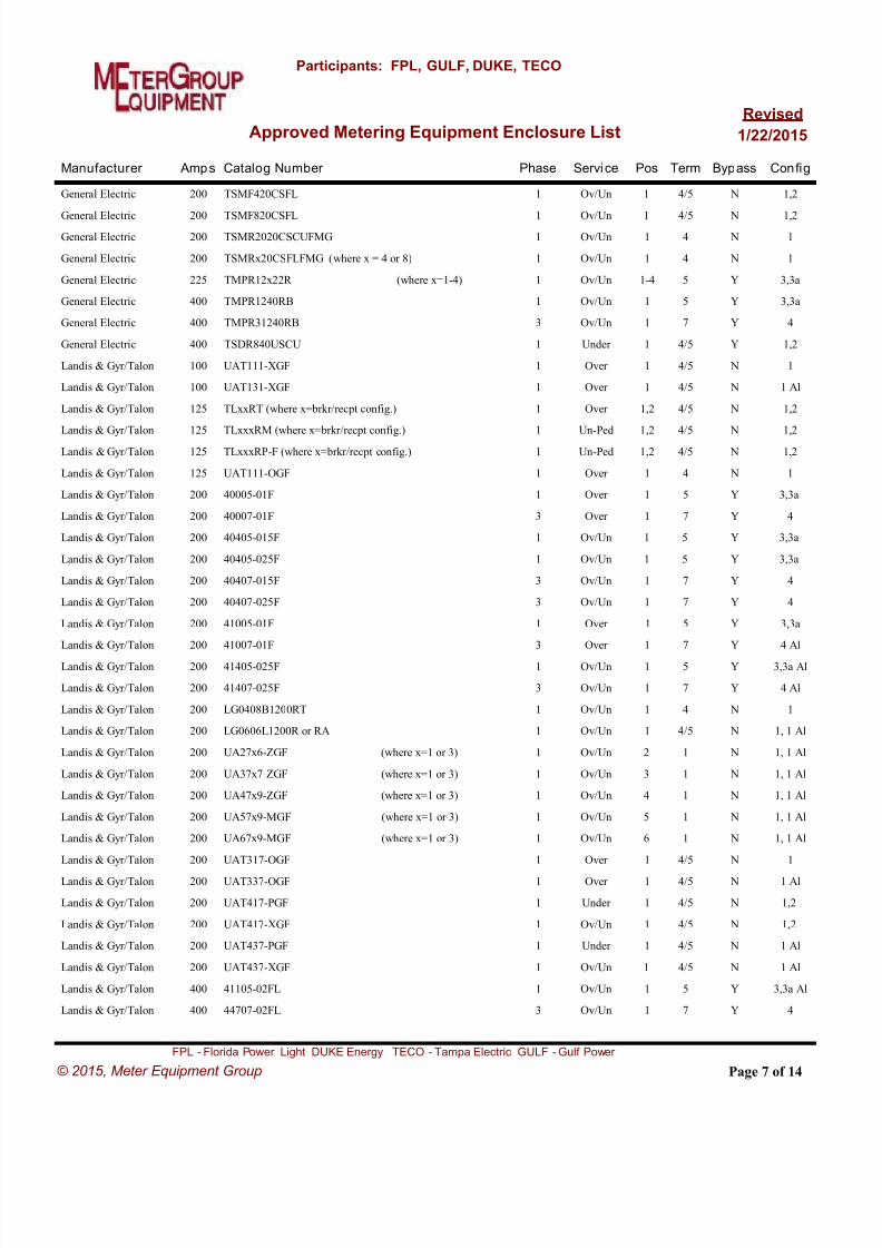
8/18/2019 electric-service-standards Florida Power Light FPL.pdf
http://slidepdf.com/reader/full/electric-service-standards-florida-power-light-fplpdf 87/118
Manufacturer Catalog Number Amps Phase Service Pos Term Bypass Config
Approved Metering Equipment Enclosure List
Participants: FPL, GULF, DUKE, TECO
Revised
1/22/2015
General Electric TSMF420CSFL200 1 Ov/Un 1 4/5 N 1,2
General Electric TSMF820CSFL200 1 Ov/Un 1 4/5 N 1,2
General Electric TSMR2020CSCUFMG200 1 Ov/Un 1 4 N 1
General Electric TSMRx20CSFLFMG (where x = 4 or 8)200 1 Ov/Un 1 4 N 1
General Electric TMPR12x22R (where x=1-4)225 1 Ov/Un 1-4 5 Y 3,3a
General Electric TMPR1240RB400 1 Ov/Un 1 5 Y 3,3a
General Electric TMPR31240RB400 3 Ov/Un 1 7 Y 4
General Electric TSDR840USCU400 1 Under 1 4/5 Y 1,2
Landis & Gyr/Talon UAT111-XGF100 1 Over 1 4/5 N 1
Landis & Gyr/Talon UAT131-XGF100 1 Over 1 4/5 N 1 Al
Landis & Gyr/Talon TLxxRT (where x=brkr/recpt config.)125 1 Over 1,2 4/5 N 1,2
Landis & Gyr/Talon TLxxxRM (where x=brkr/recpt config.)125 1 Un-Ped 1,2 4/5 N 1,2
Landis & Gyr/Talon TLxxxRP-F (where x=brkr/recpt config.)125 1 Un-Ped 1,2 4/5 N 1,2
Landis & Gyr/Talon UAT111-OGF125 1 Over 1 4 N 1
Landis & Gyr/Talon 40005-01F200 1 Over 1 5 Y 3,3a
Landis & Gyr/Talon 40007-01F200 3 Over 1 7 Y 4
Landis & Gyr/Talon 40405-015F200 1 Ov/Un 1 5 Y 3,3a
Landis & Gyr/Talon 40405-025F200 1 Ov/Un 1 5 Y 3,3a
Landis & Gyr/Talon 40407-015F200 3 Ov/Un 1 7 Y 4
Landis & Gyr/Talon 40407-025F200 3 Ov/Un 1 7 Y 4
Landis & Gyr/Talon 41005-01F200 1 Over 1 5 Y 3,3a
Landis & Gyr/Talon 41007-01F200 3 Over 1 7 Y 4 Al
Landis & Gyr/Talon 41405-025F200 1 Ov/Un 1 5 Y 3,3a Al
Landis & Gyr/Talon 41407-025F200 3 Ov/Un 1 7 Y 4 Al
Landis & Gyr/Talon LG0408B1200RT200 1 Ov/Un 1 4 N 1
Landis & Gyr/Talon LG0606L1200R or RA200 1 Ov/Un 1 4/5 N 1, 1 Al
Landis & Gyr/Talon UA27x6-ZGF (where x=1 or 3)200 1 Ov/Un 2 1 N 1, 1 Al
Landis & Gyr/Talon UA37x7-ZGF (where x=1 or 3)200 1 Ov/Un 3 1 N 1, 1 Al
Landis & Gyr/Talon UA47x9-ZGF (where x=1 or 3)200 1 Ov/Un 4 1 N 1, 1 Al
Landis & Gyr/Talon UA57x9-MGF (where x=1 or 3)200 1 Ov/Un 5 1 N 1, 1 Al
Landis & Gyr/Talon UA67x9-MGF (where x=1 or 3)200 1 Ov/Un 6 1 N 1, 1 Al
Landis & Gyr/Talon UAT317-OGF200 1 Over 1 4/5 N 1
Landis & Gyr/Talon UAT337-OGF200 1 Over 1 4/5 N 1 Al
Landis & Gyr/Talon UAT417-PGF200 1 Under 1 4/5 N 1,2
Landis & Gyr/Talon UAT417-XGF200 1 Ov/Un 1 4/5 N 1,2
Landis & Gyr/Talon UAT437-PGF200 1 Under 1 4/5 N 1 Al
Landis & Gyr/Talon UAT437-XGF200 1 Ov/Un 1 4/5 N 1 Al
Landis & Gyr/Talon 41105-02FL400 1 Ov/Un 1 5 Y 3,3a Al
Landis & Gyr/Talon 44707-02FL400 3 Ov/Un 1 7 Y 4
Page 7 of 14
FPL - Florida Power Light DUKE Energy TECO - Tampa Electric GULF - Gulf Power
© 2015, Meter Equipment Group

8/18/2019 electric-service-standards Florida Power Light FPL.pdf
http://slidepdf.com/reader/full/electric-service-standards-florida-power-light-fplpdf 88/118
Manufacturer Catalog Number Amps Phase Service Pos Term Bypass Config
Approved Metering Equipment Enclosure List
Participants: FPL, GULF, DUKE, TECO
Revised
1/22/2015
Landis & Gyr/Talon 47705-02FL400 1 Ov/Un 1 5 Y 3,3a
Landis & Gyr/Talon 49005-02FL400 1 Ov/Un 1 5 Y 3,3a
Landis & Gyr/Talon 49007-02FL400 3 Ov/Un 1 7 Y 4
Landis & Gyr/Talon 49105-02FL400 1 Ov/Un 1 5 Y 3,3a Al
Landis & Gyr/Talon 49107-02FL400 3 Ov/Un 1 7 Y 4 Al
Landis & Gyr/Talon 9817-9526 (Requires Ridged Lugs) FPL ONLY600 3 Ov/Un 1 7 Y 5
Landis & Gyr/Talon 9817-9527 (Requires Ridged Lugs) FPL ONLY600 3 Ov/Un 1 7 Y 5 Al
Landis+Gyr/Talon 9817-8061600 3 OH/UG 4 7 Y 3
Midwest R158CR2TLFMG150 1 Ov/Un 1 4 N 1
Midwest MPx00S0FMG (where x=1-4)200 1 Under 1-4 4/5 N 1,2 Al
Midwest MPx00S1FMG (where x=1-4)200 1 Under 1-4 4/5 N 1,2 Al
Midwest MPx20B0FMG (where x=1-4)200 1 Under 1-4 4/5 N 1,2 Al
Midwest MPx20B1FMG (where x=1-4)200 1 Under 1-4 4/5 N 1,2 Al
Midwest R208CR2TLFMG200 1 Ov/Un 1 4 N 1
Midwest R256EB118FMG200 1 Ov/Un 1 4 N 1, Al
Midwest R256EB1FMG200 1 Ov/Un 1 4 N 1
Midwest R256EB1NFMG200 1 Ov/Un 1 4 N 1
Midwest RS45524CFMG400 1 Under 1 4/5 Y 1,2
Milbank U349y-XL-HSP (where y=2-6)100 1 Ov/Un 2-6 4/5 N 1,2
Milbank U513y-O-100P-FMG (where y=6-7)100 1 Un-Ped 1-2 4/5 N 1,2
Milbank U513y-O-100S-FMG (where y=6-7)100 1 Un-Ped 1-2 4/5 N 1,2
Milbank UAP349y-XL-HSP (where y=2-6)100 1 Ov/Un 2-6 4/5 N 1,2 Al
Milbank U285y-X-HSP (where y=2-6)125 1 Ov/Un 2-6 4/5 N 1,2
Milbank U3505-XL-HSP125 1 Ov/Un 1 5 Y 3,3a
Milbank U3505-XL-TG-HSP125 1 Ov/Un 1 5 Y 3,3a
Milbank U3506-XL-TG-HSP125 3 Ov/Un 1 7 Y 4
Milbank U513y-O-125P-FMG (where y=6-7)125 1 Under 1-2 4/5 N 1,2
Milbank U513y-O-125S-FMG (where y=6-7)125 1 Under 1-2 4/5 N 1,2
Milbank U8435-XL-TG-HSP125 1 Over 1 4/5 N 1,2
Milbank UAP3505-XL-TG-HSP125 1 Ov/Un 1 5 Y 3,3a Al
Milbank UAP3506-XL-TG-HSP125 3 Ov/Un 1 7 Y 4 Al
Milbank UAP8435-XL-TG-HSP125 1 Ov/Un 1 4/5 N 1,2 Al
Milbank U123y-X-HSP (where y=2-6)150 1 Ov/Un 2-6 4/5 N 1,2
Milbank U3312-XL-TG-HSP150 1 Ov/Un 1 4/5 N 1,2
Milbank U513y-O-150P-FMG (where y=6-7)150 1 Under 1-2 4/5 N 1,2
Milbank U513y-O-150S-FMG (where y=6-7)150 1 Under 1-2 4/5 N 1,2
Milbank UAP123y-X-HSP (where y=2-3)150 1 Ov/Un 2-3 4/5 N 1,2 Al
Milbank U125Y-X-HSP (where y=2-6)200 1 Ov/Un 2-6 4/5 N 1,2
Milbank U1980-O-HSP200 1 Under 1 4/5 N 1,2
Page 8 of 14
FPL - Florida Power Light DUKE Energy TECO - Tampa Electric GULF - Gulf Power
© 2015, Meter Equipment Group

8/18/2019 electric-service-standards Florida Power Light FPL.pdf
http://slidepdf.com/reader/full/electric-service-standards-florida-power-light-fplpdf 89/118
Manufacturer Catalog Number Amps Phase Service Pos Term Bypass Config
Approved Metering Equipment Enclosure List
Participants: FPL, GULF, DUKE, TECO
Revised
1/22/2015
Milbank U273y-XT-HSP (where y=2-6)200 3 Ov/Un 2-6 7 Y 4
Milbank U286y-X-HSP (where y=2-6)200 1 Ov/Un 2-6 4/5 N 1,2
Milbank U287y-XT-HSP (where y=2-6)200 1 Ov/Un 2-6 5 Y 3,3a
Milbank U3296-X-HSP200 1 Ov/Un 1 5 Y 3,3a
Milbank U3306-X-HSP200 3 Ov/Un 1 7 Y 4
Milbank U3850-XL-TG-HSP-PL200 1 Ov/Un 1 4/5 N 1,2
Milbank U5136-O-yyy-FMG (where yyy=41,55,75,332,552)200 1 Un-Ped 1 4/5 N 1,2
Milbank U5137-O-yyy-FMG (where yyy=41,55,75,332,552)200 1 Un-Ped 2 4/5 N 1,2
Milbank U513y-O-200P-FMG (where y=6-7)200 1 Un-Ped 1-2 4/5 N 1,2
Milbank U513y-O-200S-FMG (where y=6-7)200 1 Un-Ped 1-2 4/5 N 1,2
Milbank U513y-O-FMG (where y=6-7)200 1 Un-Ped 1-2 4/5 N 1,2
Milbank U7021-RL-TG-HSP200 1 Over 1 4/5 N 1,2
Milbank U7040-O-TG-HSP200 1 Under 1 4 N 1,2
Milbank U7040-XL-TG-HSP200 1 Ov/Un 1 4/5 N 1,2
Milbank U7043-XL-TG200 1 Ov/Un 1 4/5 N 1,2
Milbank U9550-RRL-QG-HSP200 1 Over 1 5 Y 3,3a
Milbank U9551-X-QG-HSP200 1 Ov/Un 1 5 Y 3,3a
Milbank U9700-RRL-QG-HSP200 3 Over 1 7 Y 4
Milbank U9701-X-QG-HSP200 3 Ov/Un 1 7 Y 4
Milbank U9801-X-QG -HSP200 1 Ov/Un 1 4 Y 1,2
Milbank UAP125y-X-HSP (where y=2-6)200 1 Ov/Un 2-6 4/5 Y 1,2 Al
Milbank UAP1980-O-HSP200 1 Under 1 4/5 N 1,2 Al
Milbank UAP3296-X-HSP200 1 Ov/Un 1 5 Y 3,3a Al
Milbank UAP3306-X-HSP200 3 Ov/Un 1 7 Y 4 Al
Milbank UAP5024-XL200 1 Ov/Un 1 4 N 1
Milbank UAP5024-XL-FMG200 1 Ov/Un 1 4 N 1
Milbank UAP7021-RL-TG-HSP200 1 Over 1 4/5 N 1,2 Al
Milbank UAP7040-O-TG-HSP200 1 Under 1 4/5 N 1,2 Al
Milbank UAP7040-XL-TG-HSP200 1 Ov/Un 1 4/5 N 1,2 Al
Milbank UAP9550-RRL-QG-HSP200 1 Over 1 5 Y 3,3a Al
Milbank UAP9551-X-QG-HSP200 1 Ov/Un 1 5 Y 3,3a Al
Milbank UAP9700-RRL-QG-HSP200 3 Over 1 7 Y 4 Al
Milbank UAP9701-X-QG-HSP200 3 Ov/Un 1 7 Y 4 Al
Milbank U2120-O-HSP400 3 Ov/Un 1 7 Y 4
Milbank U2120-X-HSP400 3 Under 1 7 Y 4
Milbank U2124-O-HSP400 1 Under 1 4/5 Y 4
Milbank U3313-X-HSP400 1 Ov/Un 1 5 Y 3,3a
Milbank U3566-X-HSP400 3 Ov/Un 1 7 Y 4
Milbank U3949-X-HSP400 1 Over 1 5 Y 3,3a
Page 9 of 14
FPL - Florida Power Light DUKE Energy TECO - Tampa Electric GULF - Gulf Power
© 2015, Meter Equipment Group

8/18/2019 electric-service-standards Florida Power Light FPL.pdf
http://slidepdf.com/reader/full/electric-service-standards-florida-power-light-fplpdf 90/118
Manufacturer Catalog Number Amps Phase Service Pos Term Bypass Config
Approved Metering Equipment Enclosure List
Participants: FPL, GULF, DUKE, TECO
Revised
1/22/2015
Milbank U5864-X-HSP400 1 Ov/Un 1 5 Y 3, 3a
Milbank U5864-X-HSP400 1 Ov/Un 1 5 Y 3, 3a
Milbank UAP2124-O-HSP400 1 Under 1 4/5 Y 4 Al
Milbank UAP3313-X-HSP400 1 Ov/Un 1 5 Y 3,3a Al
Milbank UAP3566-X-HSP400 3 Ov/Un 1 7 Y 4 Al
Milbank UAP3949-X-HSP400 1 Over 1 5 Y 3,3a Al
Milbank UAP5864-X-HSP400 1 Ov/Un 1 5 Y 3, 3a Al
Milbank U4667-X-8528 (Req. Ridged Lugs) FPL ONLY600 3 Ov/Un 1 7 Y 5
Milbank U4667-XT-9526(Requires Ridged Lugs) FPL ONLY600 3 Ov/Un 1 7 Y 5
Milbank UA4667-X-8529 (Req. Ridged Lugs) FPL ONLY600 3 Ov/Un 1 7 Y 5 Al
Milbank UA4667-XT-9527(Requires Ridged Lugs) FPL ONLY600 3 Ov/Un 1 7 Y 5 Al
Murray RJ103AXF100 1 Over 1 4 N 1
Murray JA1224B1125125 1 Ov/Un 1 4/5 N 1,2
Murray JA0408B1150T or RT150 1 Ov/Un 1 4 N 1
Murray JA0816B1150CT or RCT150 1 Ov/Un 1 4 N 1
Murray JA0816B1150TH150 1 Ov/Un 1 4/5 N 1,2
Murray JA2040B1150150 1 Ov/Un 1 4/5 N 1,2
Murray JA2040B1150RC150 1 Ov/Un 1 4 N 1
Murray JA204LS150 1 Ov/Un 1 4/5 N 1,2
Murray JC0202B1150150 1 Ov/Un 1 4/5 N 1,2
Murray JA0408B1200T or RT200 1 Ov/Un 1 4 N 1
Murray JA0606L1200R or RA200 1 Ov/Un 1 4/5 N 1, 1 Al
Murray JA0816B1200CT or RCT200 1 Ov/Un 1 4 N 1
Murray JA0816B1200TH200 1 Ov/Un 1 4/5 N 1,2
Murray JA2040B1200200 1 Ov/Un 1 4/5 N 1,2
Murray JA2040B1200RC200 1 Ov/Un 1 4 N 1
Murray JA204TS200 1 Ov/Un 1 4/5 N 1,2
Murray JC0202B1200200 1 Ov/Un 1 4/5 N 1,2
Murray RB103AR 200 1 Ov/Un 1 4/5 N 1,2
Murray RH173CRF200 1 Ov/Un 1 5 Y 3,3a
Murray RH173GRF200 3 Ov/Un 1 7 Y 4
Murray RS103AVF200 1 Under 1 4/5 N 1,2
Murray RS103AXF200 1 Over 1 4 N 1
Murray JA0816B1350RLTM400 1 Ov/Un 1 4/5 Y 1,2
Murray JA0816B1400RLTM400 1 Ov/Un 1 4/5 Y 1,2
Murray JC0404L1400RLM400 1 Ov/Un 1 4/5 Y 1,2
Murray JC0408B1400RLTM400 1 Ov/Un 1 4/5 Y 1,2
Siemens MC1224B1125125 1 Ov/Un 1 4/5 N 1,2
Siemens SPxx11RJ (where xx=22, 33, 44, 45, 46, 65, 66)125 1 Ov/Un 2-6 4/5 N 1,2
Page 10 of 14
FPL - Florida Power Light DUKE Energy TECO - Tampa Electric GULF - Gulf Power
© 2015, Meter Equipment Group
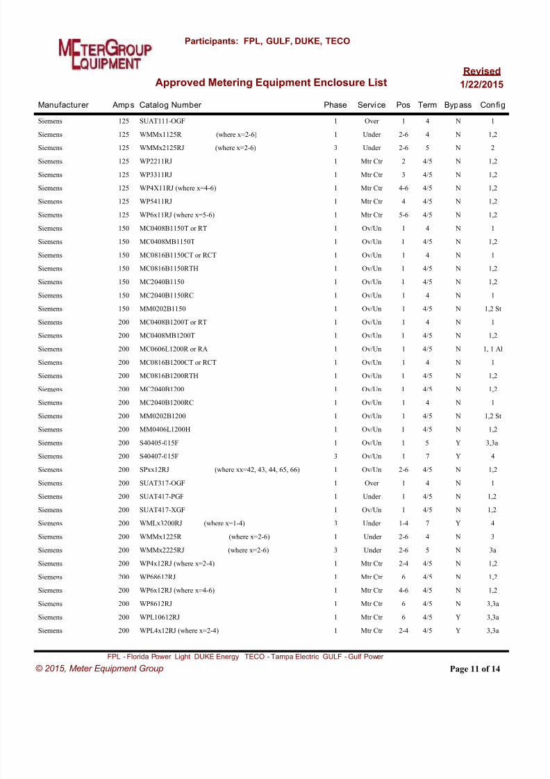
8/18/2019 electric-service-standards Florida Power Light FPL.pdf
http://slidepdf.com/reader/full/electric-service-standards-florida-power-light-fplpdf 91/118
Manufacturer Catalog Number Amps Phase Service Pos Term Bypass Config
Approved Metering Equipment Enclosure List
Participants: FPL, GULF, DUKE, TECO
Revised
1/22/2015
Siemens SUAT111-OGF125 1 Over 1 4 N 1
Siemens WMMx1125R (where x=2-6)125 1 Under 2-6 4 N 1,2
Siemens WMMx2125RJ (where x=2-6)125 3 Under 2-6 5 N 2
Siemens WP2211RJ125 1 Mtr Ctr 2 4/5 N 1,2
Siemens WP3311RJ125 1 Mtr Ctr 3 4/5 N 1,2
Siemens WP4X11RJ (where x=4-6)125 1 Mtr Ctr 4-6 4/5 N 1,2
Siemens WP5411RJ125 1 Mtr Ctr 4 4/5 N 1,2
Siemens WP6x11RJ (where x=5-6)125 1 Mtr Ctr 5-6 4/5 N 1,2
Siemens MC0408B1150T or RT150 1 Ov/Un 1 4 N 1
Siemens MC0408MB1150T150 1 Ov/Un 1 4/5 N 1,2
Siemens MC0816B1150CT or RCT150 1 Ov/Un 1 4 N 1
Siemens MC0816B1150RTH150 1 Ov/Un 1 4/5 N 1,2
Siemens MC2040B1150150 1 Ov/Un 1 4/5 N 1,2
Siemens MC2040B1150RC150 1 Ov/Un 1 4 N 1
Siemens MM0202B1150150 1 Ov/Un 1 4/5 N 1,2 St
Siemens MC0408B1200T or RT200 1 Ov/Un 1 4 N 1
Siemens MC0408MB1200T200 1 Ov/Un 1 4/5 N 1,2
Siemens MC0606L1200R or RA200 1 Ov/Un 1 4/5 N 1, 1 Al
Siemens MC0816B1200CT or RCT200 1 Ov/Un 1 4 N 1
Siemens MC0816B1200RTH200 1 Ov/Un 1 4/5 N 1,2
Siemens MC2040B1200200 1 Ov/Un 1 4/5 N 1,2
Siemens MC2040B1200RC200 1 Ov/Un 1 4 N 1
Siemens MM0202B1200200 1 Ov/Un 1 4/5 N 1,2 St
Siemens MM0406L1200H200 1 Ov/Un 1 4/5 N 1,2
Siemens S40405-015F200 1 Ov/Un 1 5 Y 3,3a
Siemens S40407-015F200 3 Ov/Un 1 7 Y 4
Siemens SPxx12RJ (where xx=42, 43, 44, 65, 66)200 1 Ov/Un 2-6 4/5 N 1,2
Siemens SUAT317-OGF200 1 Over 1 4 N 1
Siemens SUAT417-PGF200 1 Under 1 4/5 N 1,2
Siemens SUAT417-XGF200 1 Ov/Un 1 4/5 N 1,2
Siemens WMLx3200RJ (where x=1-4)200 3 Under 1-4 7 Y 4
Siemens WMMx1225R (where x=2-6)200 1 Under 2-6 4 N 3
Siemens WMMx2225RJ (where x=2-6)200 3 Under 2-6 5 N 3a
Siemens WP4x12RJ (where x=2-4)200 1 Mtr Ctr 2-4 4/5 N 1,2
Siemens WP68612RJ200 1 Mtr Ctr 6 4/5 N 1,2
Siemens WP6x12RJ (where x=4-6)200 1 Mtr Ctr 4-6 4/5 N 1,2
Siemens WP8612RJ200 1 Mtr Ctr 6 4/5 N 3,3a
Siemens WPL10612RJ200 1 Mtr Ctr 6 4/5 Y 3,3a
Siemens WPL4x12RJ (where x=2-4)200 1 Mtr Ctr 2-4 4/5 Y 3,3a
Page 11 of 14
FPL - Florida Power Light DUKE Energy TECO - Tampa Electric GULF - Gulf Power
© 2015, Meter Equipment Group

8/18/2019 electric-service-standards Florida Power Light FPL.pdf
http://slidepdf.com/reader/full/electric-service-standards-florida-power-light-fplpdf 92/118
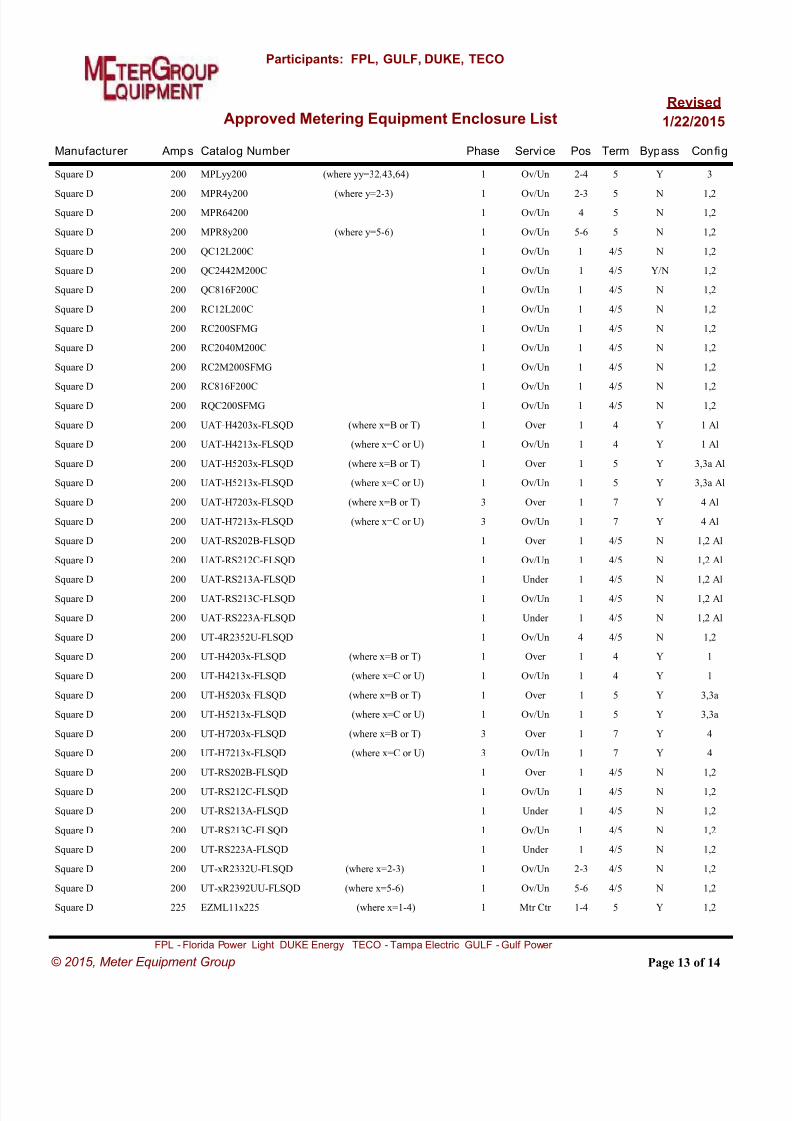
8/18/2019 electric-service-standards Florida Power Light FPL.pdf
http://slidepdf.com/reader/full/electric-service-standards-florida-power-light-fplpdf 93/118
Manufacturer Catalog Number Amps Phase Service Pos Term Bypass Config
Approved Metering Equipment Enclosure List
Participants: FPL, GULF, DUKE, TECO
Revised
1/22/2015
Square D MPLyy200 (where yy=32,43,64)200 1 Ov/Un 2-4 5 Y 3
Square D MPR4y200 (where y=2-3)200 1 Ov/Un 2-3 5 N 1,2
Square D MPR64200200 1 Ov/Un 4 5 N 1,2
Square D MPR8y200 (where y=5-6)200 1 Ov/Un 5-6 5 N 1,2
Square D QC12L200C200 1 Ov/Un 1 4/5 N 1,2
Square D QC2442M200C200 1 Ov/Un 1 4/5 Y/N 1,2
Square D QC816F200C200 1 Ov/Un 1 4/5 N 1,2
Square D RC12L200C200 1 Ov/Un 1 4/5 N 1,2
Square D RC200SFMG200 1 Ov/Un 1 4/5 N 1,2
Square D RC2040M200C200 1 Ov/Un 1 4/5 N 1,2
Square D RC2M200SFMG200 1 Ov/Un 1 4/5 N 1,2
Square D RC816F200C200 1 Ov/Un 1 4/5 N 1,2
Square D RQC200SFMG200 1 Ov/Un 1 4/5 N 1,2
Square D UAT-H4203x-FLSQD (where x=B or T)200 1 Over 1 4 Y 1 Al
Square D UAT-H4213x-FLSQD (where x=C or U)200 1 Ov/Un 1 4 Y 1 Al
Square D UAT-H5203x-FLSQD (where x=B or T)200 1 Over 1 5 Y 3,3a Al
Square D UAT-H5213x-FLSQD (where x=C or U)200 1 Ov/Un 1 5 Y 3,3a Al
Square D UAT-H7203x-FLSQD (where x=B or T)200 3 Over 1 7 Y 4 Al
Square D UAT-H7213x-FLSQD (where x=C or U)200 3 Ov/Un 1 7 Y 4 Al
Square D UAT-RS202B-FLSQD200 1 Over 1 4/5 N 1,2 Al
Square D UAT-RS212C-FLSQD200 1 Ov/Un 1 4/5 N 1,2 Al
Square D UAT-RS213A-FLSQD200 1 Under 1 4/5 N 1,2 Al
Square D UAT-RS213C-FLSQD200 1 Ov/Un 1 4/5 N 1,2 Al
Square D UAT-RS223A-FLSQD200 1 Under 1 4/5 N 1,2 Al
Square D UT-4R2352U-FLSQD200 1 Ov/Un 4 4/5 N 1,2
Square D UT-H4203x-FLSQD (where x=B or T)200 1 Over 1 4 Y 1
Square D UT-H4213x-FLSQD (where x=C or U)200 1 Ov/Un 1 4 Y 1
Square D UT-H5203x-FLSQD (where x=B or T)200 1 Over 1 5 Y 3,3a
Square D UT-H5213x-FLSQD (where x=C or U)200 1 Ov/Un 1 5 Y 3,3a
Square D UT-H7203x-FLSQD (where x=B or T)200 3 Over 1 7 Y 4
Square D UT-H7213x-FLSQD (where x=C or U)200 3 Ov/Un 1 7 Y 4
Square D UT-RS202B-FLSQD200 1 Over 1 4/5 N 1,2
Square D UT-RS212C-FLSQD200 1 Ov/Un 1 4/5 N 1,2
Square D UT-RS213A-FLSQD200 1 Under 1 4/5 N 1,2
Square D UT-RS213C-FLSQD200 1 Ov/Un 1 4/5 N 1,2
Square D UT-RS223A-FLSQD200 1 Under 1 4/5 N 1,2
Square D UT-xR2332U-FLSQD (where x=2-3)200 1 Ov/Un 2-3 4/5 N 1,2
Square D UT-xR2392UU-FLSQD (where x=5-6)200 1 Ov/Un 5-6 4/5 N 1,2
Square D EZML11x225 (where x=1-4)225 1 Mtr Ctr 1-4 5 Y 1,2
Page 13 of 14
FPL - Florida Power Light DUKE Energy TECO - Tampa Electric GULF - Gulf Power
© 2015, Meter Equipment Group
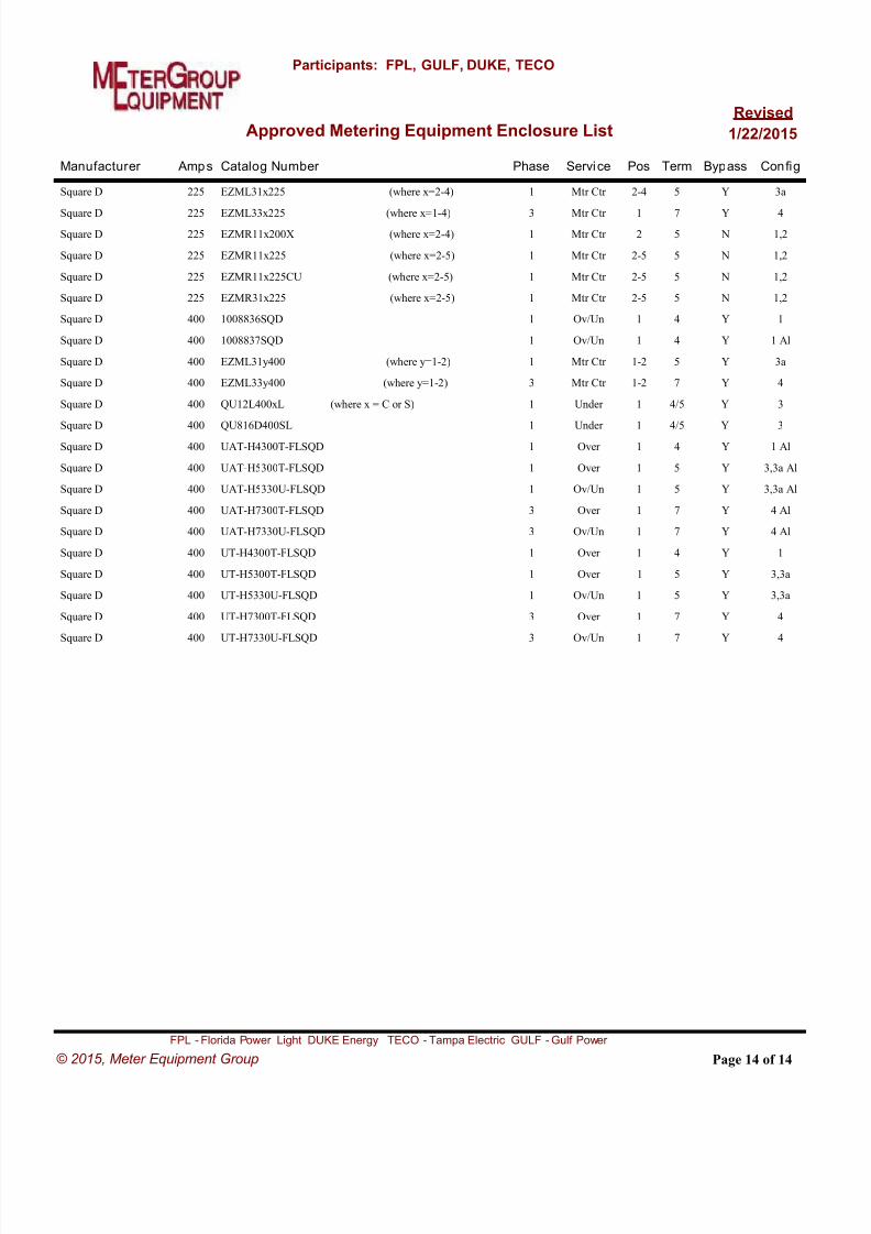
8/18/2019 electric-service-standards Florida Power Light FPL.pdf
http://slidepdf.com/reader/full/electric-service-standards-florida-power-light-fplpdf 94/118

8/18/2019 electric-service-standards Florida Power Light FPL.pdf
http://slidepdf.com/reader/full/electric-service-standards-florida-power-light-fplpdf 95/118
1/22/2015 pproved Transformer Rated Equipment
Florida Power & Light
Note: Instrument Transformer Rated Meter Sockets and Cabinets on this list are only approved for use in the FPL Service
Area. Before purchase, please contact you FPL Representative. Instrument Transformer Metering must be approved byFPL.
Manufacture Amps Catalog Number Phase Service Pos Term Test Switch Config
INSTRUMENT RATED METER SOCKETS
Meter Devices 602U3010C13-387 (TUV Steel) 6-1220 3 Ov/Un 1 13 Y
Meter Devices 602U3010C6-388 (Q6 Steel) 6-1220 1 Ov/Un 1 6 Y
Meter Devices 605U8010C13-934 (TUV Steel Snap 2) 6-1220 3 Ov/Un 1 13 Y
Meter Devices 652U3010C13-387 (TUV Alum) 6-1220 3 Ov/Un 1 13 Y
Meter Devices 652U3010C6-388 (Q6 Alum) 6-1220 1 Ov/Un 1 6 Y
Meter Devices 655U8010C13-934 (TUV Alum Snap 2) 6-1220 3 Ov/Un 1 13 Y
Landis & Gyr/Talon 9837-0422 (PTS-6 Aluminum) 6-1220 1 Ov/Un 1 6 Y
Landis & Gyr/Talon 9837-0423 (PTS-6 Steel) 6-1220 1 Ov/Un 1 6 Y
Landis & Gyr/Talon 9837-0424 (PTS-13 Alum) 6-1220 3 Ov/Un 1 13 Y
Landis & Gyr/Talon 9837-0425 (PTS-13 Steel) 6-1220 3 Ov/Un 1 13 Y
Anchor RTSA13-13-FP&L (Alum) 6-1220 3 Ov/Un 1 13 Y
Anchor RTSA6-73-FP&L (Alum) 6-1220 1 Ov/Un 1 6 Y
Anchor RTSS13-13-FP&L (Steel) 6-1220 3 Ov/Un 1 13 Y
Anchor RTSS6-73-FP&L (Steel) 6-1220 1 Ov/Un 1 6 YCooper B-Line ST02063N1AL1F (Q6 ALUM) 6-1220 1 Ov/Un 1 6 Y
Cooper B-Line ST02063N1GR1F (Q6 STEEL) 6-1220 1 Ov/Un 1 6 Y
Cooper B-Line ST02133N1AL1F (TUV ALUM) 6-1220 3 Ov/Un 1 13 Y
Cooper B-Line ST02133N1GR1F (TUV STEEL) 6-1220 3 Ov/Un 1 13 Y
Milbank UAPC4511 (Q6 Alum) 6-1220 1 Ov/Un 1 6 Y
Milbank UAPC4512 (TUV Alum) 6-1220 3 Ov/Un 1 13 Y
Milbank UC4511 (Q6 Steel) 6-1220 1 Ov/Un 1 6 Y
Milbank UC4512 (TUV Steel) 6-1220 3 Ov/Un 1 13 Y
Page 1 of 6
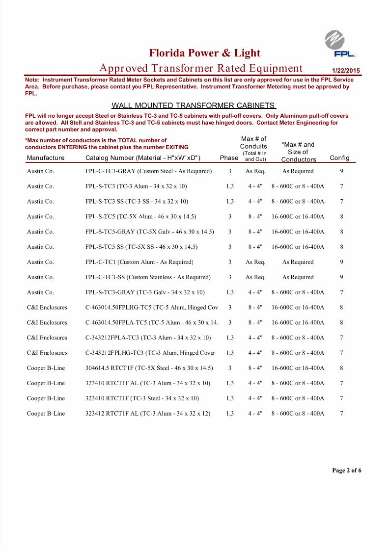
8/18/2019 electric-service-standards Florida Power Light FPL.pdf
http://slidepdf.com/reader/full/electric-service-standards-florida-power-light-fplpdf 96/118
1/22/2015 pproved Transformer Rated Equipment
Florida Power & Light
Note: Instrument Transformer Rated Meter Sockets and Cabinets on this list are only approved for use in the FPL Service
Area. Before purchase, please contact you FPL Representative. Instrument Transformer Metering must be approved by
FPL.
Manufacture Catalog Number (Material - H"xW"xD") Config
WALL MOUNTED TRANSFORMER CABINETS
Phase(Total # In
and Out)
Max # of
Conduits *Max # andSize of
Conductors
FPL will no longer accept Steel or Stainless TC-3 and TC-5 cabinets with pull-off covers. Only Aluminum pull-off covers
are allowed. All Stell and Stainless TC-3 and TC-5 cabinets must have hinged doors. Contact Meter Engineering for
correct part number and approval.
*Max number of conductors is the TOTAL number of
conductors ENTERING the cabinet plus the number EXITING
Austin Co. FPL-C-TC1-GRAY (Custom Steel - As Required) 9As RequiredAs Req.3
Austin Co. FPL-S-TC3 (TC-3 Alum - 34 x 32 x 10) 78 - 600C or 8 - 400A4 - 4"1,3
Austin Co. FPL-S-TC3 SS (TC-3 SS - 34 x 32 x 10) 78 - 600C or 8 - 400A4 - 4"1,3
Austin Co. FPL-S-TC5 (TC-5X Alum - 46 x 30 x 14.5) 816-600C or 16-400A8 - 4"3
Austin Co. FPL-S-TC5-GRAY (TC-5X Galv - 46 x 30 x 14.5) 816-600C or 16-400A8 - 4"3
Austin Co. FPL-S-TC5 SS (TC-5X SS - 46 x 30 x 14.5) 816-600C or 16-400A8 - 4"3
Austin Co. FPL-C-TC1 (Custom Alum - As Required) 9As RequiredAs Req.3
Austin Co. FPL-C-TC1-SS (Custom Stainless - As Required) 9As RequiredAs Req.3
Austin Co. FPL-S-TC3-GRAY (TC-3 Galv - 34 x 32 x 10) 78 - 600C or 8 - 400A4 - 4"1,3
C&I Enclosures C-463014.50FPLHG-TC5 (TC-5 Alum, Hinged Cov 816-600C or 16-400A8 - 4"3
C&I Enclosures C-463014.50FPLA-TC5 (TC-5 Alum - 46 x 30 x 14. 816-600C or 16-400A8 - 4"3
C&I Enclosures C-343212FPLA-TC3 (TC-3 Alum - 34 x 32 x 10) 78 - 600C or 8 - 400A4 - 4"1,3
C&I Enclosures C-343212FPLHG-TC3 (TC-3 Alum, Hinged Cover 78 - 600C or 8 - 400A4 - 4"1,3
Cooper B-Line 304614.5 RTCT1F (TC-5X Steel - 46 x 30 x 14.5) 816-600C or 16-400A8 - 4"3
Cooper B-Line 323410 RTCT1F AL (TC-3 Alum - 34 x 32 x 10) 78 - 600C or 8 - 400A4 - 4"1,3
Cooper B-Line 323410 RTCT1F (TC-3 Steel - 34 x 32 x 10) 78 - 600C or 8 - 400A4 - 4"1,3
Cooper B-Line 323412 RTCT1F AL (TC-3 Alum - 34 x 32 x 12) 78 - 600C or 8 - 400A4 - 4"1,3
Page 2 of 6
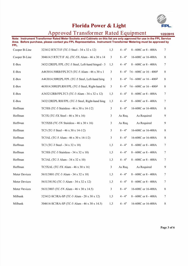
8/18/2019 electric-service-standards Florida Power Light FPL.pdf
http://slidepdf.com/reader/full/electric-service-standards-florida-power-light-fplpdf 97/118
1/22/2015 pproved Transformer Rated Equipment
Florida Power & Light
Note: Instrument Transformer Rated Meter Sockets and Cabinets on this list are only approved for use in the FPL Service
Area. Before purchase, please contact you FPL Representative. Instrument Transformer Metering must be approved by
FPL.Cooper B-Line 323412 RTCT1F (TC-3 Steel - 34 x 32 x 12) 78 - 600C or 8 - 400A4 - 4"1,3
Cooper B-Line 304614.5 RTCT1F AL (TC-5X Alum - 46 x 30 x 14 816-600C or 16-400A8 - 4"3
E-Box 343212REPL/FPL (TC-3 Steel, Left-hand hinged - 3 78 - 600C or 8 - 400A4 - 4"1,3
E-Box A463014.50RB/FPLTC5 (TC-5 Alum - 46 x 30 x 1 86 - 600C or 16 - 4008 - 4"3
E-Box A463014.50REPL/FPL (TC-5 Steel, Left-hand hing 86 - 600C or 16 - 4008 - 4"3
E-Box 463014.50REPLRH/FPL (TC-5 Steel, Right-hand hi 86 - 600C or 16 - 4008 - 4"3
E-Box A343212RB/FPLTC3 (TC-3 Alum - 34 x 32 x 12) 78 - 600C or 8 - 400A4 - 4"1,3
E-Box 343212REPL/RH/FPL (TC-3 Steel, Right-hand hing 78 - 600C or 8 - 400A4 - 4"1,3
Hoffman TC5SS (TC-5 Stainless - 46 x 30 x 14-1/2) 816-600C or 16-400A8 - 4"3
Hoffman TC5X (TC-5X Steel - 46 x 30 x 16) 9As RequiredAs Req.3
Hoffman TC5XSS (TC-5X Stainless - 46 x 30 x 16) 9As RequiredAs Req.3
Hoffman TC5 (TC-5 Steel - 46 x 30 x 14-1/2) 816-600C or 16-400A8 - 4"3
Hoffman TC5AL (TC-5 Alum - 46 x 30 x 14-1/2) 816-600C or 16-400A8 - 4"3
Hoffman TC3 (TC-3 Steel - 34 x 32 x 10) 78 - 600C or 8 - 400A4 - 4"1,3
Hoffman TC3SS (TC-3 Stainless - 34 x 32 x 10) 78 - 600C or 8 - 400A4 - 4"1,3
Hoffman TC3AL (TC-3 Alum - 34 x 32 x 10) 78 - 600C or 8 - 400A4 - 4"1,3
Hoffman TC5XAL (TC-5X Alum - 46 x 30 x 16) 9As RequiredAs Req.3
Meter Devices 561U3801 (TC-3 Alum - 34 x 32 x 10) 78 - 600C or 8 - 400A4 - 4"1,3
Meter Devices 561U3815G (TC-3 Alum - 34 x 32 x 12) 78 - 600C or 8 - 400A4 - 4"1,3
Meter Devices 561U3802 (TC-5X Alum - 46 x 30 x 14.5) 816-600C or 16-400A8 - 4"3
Milbank 323412-SC3RA-SP (TC-3 Alum - 28 x 30 x 12) 78 - 600C or 8 - 400A4 - 4"1,3
Milbank 304614-SC3RA-SP (TC-5 Alum - 46 x 30 x 14.5) 816-600C or 16-400A4 - 4"1,3
Page 3 of 6

8/18/2019 electric-service-standards Florida Power Light FPL.pdf
http://slidepdf.com/reader/full/electric-service-standards-florida-power-light-fplpdf 98/118
1/22/2015 pproved Transformer Rated Equipment
Florida Power & Light
Note: Instrument Transformer Rated Meter Sockets and Cabinets on this list are only approved for use in the FPL Service
Area. Before purchase, please contact you FPL Representative. Instrument Transformer Metering must be approved by
FPL.
Manufacture Catalog Number (Material) Config
WEATHERHEAD MOUNTED TRANSFORMER CABINETS
Phase (H" x W" x D")
Approx Size
**Note: These cabinets are NOT UL LISTED and may note be utilized in jurisdictions where listing is a requiremen
Meter Devices 508-5127** (TCWM - Steel) 1027-1/2 x 6 1/2 x 6 1/21,3
Meter Devices 558-5127** (TCWM - Alum) 1027-1/2 x 6 1/2 x 6 1/21,3
Manufacture Catalog Number (Material) Config
PRIMARY PADMOUNTED TRANSFORMER CABINETS
Phase Voltage (H"xW"xD") Amps
Max Approx Size
Meter Devices SKA270192-1AL (Aluminum) 1154 x 72 x 541x2003 25kv
Shallbetter SPMD-32522-66-AL-FPL (Aluminum) 1154 x 72 x 722x6003 25kv
Shallbetter SPMD-32522-22-AL-FPL (Aluminum) 1154 x 72 x 722x2003 25kv
Shallbetter SPMD-32522-66-SS-FPL (Stainless Steel) 1154 x 72 x 722x6003 25kv
Shallbetter SPMD-32522-22-SS-FPL (Stainless Steel) 1154 x 72 x 722x2003 25kv
SPS DFPM -3252222-AL-FPL (Aluminum) 1154 x 72 x 722x6003 25kv
SPS DFPM -3252222-AL-FPL (Aluminum) 1154 x 72 x 722x6003 25kv
SPS DFPM -3252266-AL-FPL (Aluminum) 1154 x 72 x 722x2003 25kv
SPS DFPM -3252222-SS-FPL (Stainless Steel) 1154 x 72 x 722x6003 25kv
SPS DFPM -3252266-SS-FPL (Stainless Steel) 1154 x 72 x 722x2003 25kv
Manufacture Catalog Number (Material) Config
METERING EQUIPMENT CABINETS
Useage Type (H"xW"xD")
Approx Size
Austin Co. FPL-EE-X-SS (SJB-CX Stainless) 1246 x 36 x 14X-LARGEUTILITY
Austin Co. FPL-UTB-A-GRAY (UTB Steel) 1212 x 8 x 3-3/4-UTILITY
Austin Co. FPL-UTB-A-SS (UTB Stainless) 1212 x 8 x 3-3/4-UTILITY
Page 4 of 6

8/18/2019 electric-service-standards Florida Power Light FPL.pdf
http://slidepdf.com/reader/full/electric-service-standards-florida-power-light-fplpdf 99/118
1/22/2015 pproved Transformer Rated Equipment
Florida Power & Light
Note: Instrument Transformer Rated Meter Sockets and Cabinets on this list are only approved for use in the FPL Service
Area. Before purchase, please contact you FPL Representative. Instrument Transformer Metering must be approved by
FPL.Austin Co. FPL-EE-M (SJB-28 Alum) 1228 x 30 x 14MEDUTILITY
Austin Co. FPL-EE-X-GRAY (SJB-CX Steel) 1246 x 36 x 14X-LARGEUTILITY
Austin Co. FPL-EE-X (SJB-CX Alum) 1246 x 36 x 14X-LARGEUTILITY
Austin Co. FPL-EE-L-GRAY (SJB-C Steel) 1236 x 36 x 14LARGEUTILITY
Austin Co. FPL-EE-L-SS (SJB-C Stainless) 1236 x 36 x 14LARGEUTILITY
Austin Co. FPL-EE-L (SJB-C Alum) 1236 x 36 x 14LARGEUTILITY
Austin Co. FPL-EE-M-GRAY (SJB-28 Steel) 1228 x 30 x 14MEDUTILITY
Austin Co. FPL-EE-M-SS (SJB-28 Stainless) 1228 x 30 x 14MEDUTILITY
Austin Co. FPL-UTB-A (UTB Alum) 1212 x 8 x 3-3/4-UTILITY
Meter Devices 574U3805 (SJB-C Alum) 1236 x 36 x 14LARGE
Meter Devices 557U3807 (SJB-28 Alum) 1230 x 28 x 14MED
Meter Devices 574U3807 (SJB-28 Alum) 1230 x 28 x 14MED
Meter Devices 507U3807 (SJB-28 Steel) 1230 x 28 x 14MED
Meter Devices 511U3811 (UTB Steel) 1212 x 8 x 3-3/4-UTILITY
Meter Devices 557U3806 (SJB-CS Alum) 1246 x 36 x 14X-LARGE
Meter Devices 524U3807 (SJB-28 Steel) 1230 x 28 x 14MED
Meter Devices 566U5183-FPL (UMC) 1320 x 16 x 6-UTILITY
Meter Devices 557U3805 (SJB-C Alum) 1236 x 36 x 14LARGE
Meter Devices 561U3811 (UTB Alum) 1212 x 8 x 3-3/4-UTILITY
Meter Devices 524U3806 (SJB-CS Steel) 1246 x 36 x 14X-LARGE
Meter Devices 507U3806 (SJB-CS Steel) 1246 x 36 x 14X-LARGE
Meter Devices 524U3805 (SJB-C Steel) 1236 x 36 x 14LARGE
Meter Devices 507U3805 (SJB-C Steel) 1236 x 36 x 14LARGE
Meter Devices 574U3806 (SJB-CS Alum) 1246 x 36 x 14X-LARGE
Milbank 302814-CT3RS-SP (SJB-28 Stainless) 1230 x 28 x 14MEDUTILITY
Page 5 of 6

8/18/2019 electric-service-standards Florida Power Light FPL.pdf
http://slidepdf.com/reader/full/electric-service-standards-florida-power-light-fplpdf 100/118

8/18/2019 electric-service-standards Florida Power Light FPL.pdf
http://slidepdf.com/reader/full/electric-service-standards-florida-power-light-fplpdf 101/118
Electric Service Standards
DATE
01-18-12
PREPARED BY SUBJECT
VIII. GROUNDING
SECTION: PAGE
Delivery Assurance –
Design SupportVIII: 1 of 2
© 2012, Florida Power & Light Company Page 1 of 2
VIII. GROUNDING
A. General
The Customer's service entrance installation shall satisfy all grounding requirements of the
National Electrical Code (NEC) and any applicable building codes, and is subject to acceptance of
local inspecting authorities.
FPL's service drop or service lateral includes a grounded conductor. This conductor is grounded at
the source transformer location and generally interconnected with other grounded conductors. This
grounded conductor will normally be attached to a grounding connector in the meter socket and
also to one in the service equipment and to the neutral or ground bus in the service equipment.
When meter sockets with Customer owned isolated neutrals are required by local codes, a
separate Customer owned grounding conductor shall be run by the Customer from the service
equipment to the grounding connection of the meter socket.
The NEC allows several methods of supplying a grounding electrode. A ground rod is not the onlymeans of supplying the grounding electrode. A brief discussion of the NEC requirements is
provided in the following notes and is not intended to be all-inclusive. The NEC and your local
inspecting authorities should be consulted for additional details and for those that may have
changed since the time of this printing. FPL accepts any method which satisfies the NEC and the
local inspecting authorities.
Local inspecting authorities may have more stringent requirements than the NEC. For example,
some inspecting authorities require the use of a concrete-encased electrode as described in
Article 250.52. This electrode would consist of at least 20 continuous feet of one or more bare or
zinc galvanized or other electrically conductive coated steel reinforcing bars or rods of not less
than 1/2 inch in diameter or of at least 20 feet of bare copper conductor not smaller than No. 4.
The electrode would be encased in at least 2 inches of concrete and located within or near the
bottom of a concrete foundation or footing that is in direct contact with the earth (no vapor barrier).
B. Notes on Grounding Customer's Service Entrance:
1. FPL's point of delivery includes a grounded conductor. The point of delivery is normally at the
weatherhead (in the case of an FPL overhead service lateral), the meter can (in the case of an
FPL underground service lateral), a padmounted transformer, or a vault.
2. The customer shall connect this FPL grounded conductor to the service equipment by
extending a customer-owned grounded conductor along with the other conductors of the
customer's service entrance which attach to FPL at the point of delivery. This grounded
conductor shall be extended even though it may not be required as a circuit conductor by the
NEC and shall be sized according to NEC Article 250.
3. The customer's service entrance wiring shall be grounded as required by the NEC, Article 250,and any local code in effect.
4. The grounded wiring system to each premise shall have a grounding electrode conductor
connected to a grounding electrode meeting the requirements of the NEC. This grounded
conductor shall be connected to the grounded service conductor at any accessible point on
the load side of the service drop or lateral to and including the service equipment terminals
provided to connect the grounded service conductor.
5. The equipment grounding conductor and the service equipment enclosure shall be connected
to the grounded conductor of the system within the service equipment or within the service
conductor enclosure.
8/18/2019 electric-service-standards Florida Power Light FPL.pdf
http://slidepdf.com/reader/full/electric-service-standards-florida-power-light-fplpdf 102/118
Electric Service Standards
DATE
01-18-12
PREPARED BY SUBJECT
VIII. GROUNDING
SECTION: PAGE
Delivery Assurance –
Design SupportVIII: 2 of 2
© 2012, Florida Power & Light Company Page 2 of 2
6. The grounding electrode system is discussed in Article 250.52 of the NEC. Article 250.52
states that, if available on the premises, each of the following along with any "derived"
electrodes shall be bonded together to form the grounding electrode system: (1) metal
underground water pipe 10 feet or more in length, (2) metal frame of building in direct contact
with the earth for 10 or more feet or with concrete encased hold down bolts that are connected
to a concrete encased electrode, (3) concrete encased electrode at least 20 feet in length, (4)
ground ring at least 20 feet in length, (5) rod and pipe electrodes at least 8 feet in length, (6)
other listed electrodes, or (7) plate electrodes. The rod or pipe electrode may be a 5/8”
diameter stainless steel, copper or zinc coated steel rod, or a smaller diameter listed rod, or a
pipe of at least 3/4” diameter (galvanized or coated if steel), all driven 8' into the earth. A plate
electrode shall expose not less than two square feet of surface to exterior soil. Iron or steel
plates shall be at least 1/4 inch thick and nonferrous plates shall be at least .06 inch thick. A
single rod, pipe, or plate electrode having a resistance to earth of more than 25 ohms shall
have a supplemental electrode installed no closer than 6 feet away. Aluminum electrodes ARENOT PERMITTED. A metal underground gas piping system SHALL NOT BE USED AS A
GROUNDING ELECTRODE.
7. For additional grounding information, see the National Electrical Code, Article 250, and local
building codes in effect in the area. If local building code requirements exceed those of the
National Electrical Code, installations shall comply with the local codes.

8/18/2019 electric-service-standards Florida Power Light FPL.pdf
http://slidepdf.com/reader/full/electric-service-standards-florida-power-light-fplpdf 103/118
Electric Service Standards
DATE
12-03-13
PREPARED BY SUBJECT
IX. MOTORS, CONTROLLERS and AIRCONDITIONERS
SECTION: PAGE
Delivery Assurance –
Design SupportIX: 1 of 5
© 2013, Florida Power & Light Company Page 1 of 5
IX. MOTORS, CONTROLLERS AND AIR CONDITIONERS
A. General
Before ordering or installing any large polyphase or single phase motor, FPL should be consulted
to determine the character and adequacy of the available service and the allowable starting current
at the premises to be served. This information should be passed on to the suppliers of the
proposed motorized equipment. This will assist suppliers in providing equipment and protective
devices to obtain satisfactory operation at minimum cost, considering both initial installation and
future maintenance.
Motors less than 7.5 horse power can be served with single phase service, unless three phase
service is already being supplied. Motors 7.5 to 20 horsepower require open delta service (or wye
if already being supplied), and motors larger than 20 horsepower require wye service. Availability
of three phase service should be discussed in advance with FPL.
Single phase motors larger than one-half horsepower fed from 120/240 volt circuits should beconnected for 240 volt operation. Smaller motors may be connected for 240 volts, where
practicable, at the Customer's option.
The current required to start a motor is much greater than that required to operate it at full load
after it has reached rated speed. If not controlled, this starting current may cause severe voltage
fluctuations, not only on the wiring of the Customer using the motor, but also on other Customers'
wiring. The more frequently the motor is started, the more objectionable these voltage fluctuations
become.
The National Electrical Code, in Article 430, provides a table (430.7(B)) which classifies motors by
their "locked-rotor" (starting) input requirements. A code letter is assigned to each requirement
bracket. The brackets are given in "kilovolt-amperes" per horsepower which can be easily
converted to amperes for a given motor. The starting current increases as the code letter
increases. The appropriate letter is stamped on the motor nameplate.
Using this information, FPL has prepared Table IX-1 for single phase motors, five horsepower and
below. This table lists code letters and starting currents which will be acceptable at most locations
on FPL's system. The value given is for one motor which does not start more than four times per
hour. Table IX-2 provides similar data for single phase air conditioners, but is based on the unit's
rated output rather than horsepower.
B. FPL Approval of Starting Means for Large Motors
For motors larger than those listed in Table IX-1, or which start more frequently, the Customer
may be required to provide reduced voltage or incremental starting equipment, to reduce each
step of starting current to the value shown. FPL shall be consulted and will advise the Customer of
its requirements.
In the case of three phase motors, because of the variety of service conditions and the large
number of motor sizes available, FPL shall be contacted in each case to determine if reduced
voltage or incremental starting will be required. If two or more motors are started simultaneously,
the starting limitations apply to the total current of the group.

8/18/2019 electric-service-standards Florida Power Light FPL.pdf
http://slidepdf.com/reader/full/electric-service-standards-florida-power-light-fplpdf 104/118
Electric Service Standards
DATE
12-03-13
PREPARED BY SUBJECT
IX. MOTORS, CONTROLLERS and AIRCONDITIONERS
SECTION: PAGE
Delivery Assurance –
Design SupportIX: 2 of 5
© 2013, Florida Power & Light Company Page 2 of 5
Table IX-1
Single Phase Motors Acceptable for Across the Line
Starting at Most Locations on FPL System
Horsepower Ratings by NEC Letters
No more than Four Starts Per Hour
ACCEPTABLE CODE LETTERS
HORSEPOWER 115 VOLTS(50 AMPS) 230 VOLTS MAXIMUM STEP IN
STARTING CURRENT
1/4 A THRU V A THRU V 50 AMPS
1/3 A THRU S A THRU V 50 AMPS
1/2 A THRU N A THRU V 50 AMPS
3/4 A THRU J* A THRU S 50 AMPS
1 A THRU G* A THRU P 50 AMPS
1 1/2 A THRU C* A THRU K 50 AMPS
2 A THRU H 60 AMPS
3 A THRU G 80 AMPS
5 A THRU F 120 AMPS
*These motors should be connected for 230 volt operation if feasible. TABLE IX-2
Acceptable Air Conditioning Equipment, One Phase, 240 Volts
SIZE IN TONS (NOTE 1) SIZE IN BTU *MAXIMUM ALLOWABLE STEP IN
STARTING CURRENT AT 240V
1 12,000 40 AMPS
1 1/2 18,000 60 AMPS
2 24,000 80 AMPS
3 36,000 120 AMPS
4 48,000 160 AMPS
5 (NOTE 2) 60,000 200 AMPS
Note 1: Table based on units being sized and maintained so that there will be a maximum of four starts per hour.Note 2: Better performance may sometimes be obtained by using two smaller units.
* This is the maximum allowed coincident starting current of any, or all of the system’s components (compressor, condenser
fan motor, and air handler blower motor). If the System Starting Current exceeds the values shown, the customer should
investigate the installation of either a “hard start” kit or “stage” starting (or other method recommended by the manufacturer)
to reduce the starting current to the level for which FPL’s distribution system was designed.

8/18/2019 electric-service-standards Florida Power Light FPL.pdf
http://slidepdf.com/reader/full/electric-service-standards-florida-power-light-fplpdf 105/118
Electric Service Standards
DATE
12-03-13
PREPARED BY SUBJECT
IX. MOTORS, CONTROLLERS and AIRCONDITIONERS
SECTION: PAGE
Delivery Assurance –
Design SupportIX: 3 of 5
© 2013, Florida Power & Light Company Page 3 of 5
C. Motor Protection and Power Factor
It is the customer's responsibility to ensure that all motor circuits include protectionwhich at a minimum meets the National Electrical Code and any applicable local codes.
Note: such protection is designed to protect personnel from electrical and fire hazard, it
is not intended to protect the motor from damage. For this reason, FPL recommends
that the customer add the following to motor circuits to reduce the risk of equipment
damage.
The use of automatic time delay circuit breakers or time delay fuses is strongly recommended
when protecting motors against damage from excessive currents. The time delay feature will
eliminate unnecessary operation of the breakers or blowing of fuses during motor starting or
temporary overloads.
Under Voltage Protection - A low-voltage release is designed to disconnect the motor
automatically and return the starting device to the "off" position upon partial or total failure of the
supply voltage. It is used, where applicable, for motors that cannot safely be subjected to fullvoltage at starting, or where low voltage would result in injury or damage to equipment. This
release should be of the time delay type, capable of adjustment to a maximum of at least two
seconds and set at the lowest value suitable for proper protection. FPL will be glad to advise
the Customer on the proper interval for coordination with FPL's circuit breakers. This will
prevent unnecessary disconnection of the motor on momentary voltage fluctuations or loss of
voltage.
Single Phase Protection - When installing three phase motors, the Customer should consider
the possibility of the loss of one phase, either in his own installation or in FPL's supply lines.
This "single phasing" may happen regardless of the precautions taken to avoid it, and FPL
therefore strongly recommends that devices be installed to protect the equipment against the
damage that may result.
Phase Reversal Protection - Three phase motors for applications to elevators, cranes, hoists,
well pumps or other installations where reversal of rotation might cause damage to equipment
or constitute a hazard to personnel should have phase rotation protection.
Reclose Protection - Motors which cannot be safely subjected to full voltage starting, or
processes which may create a safety hazard upon an uncontrolled re-start, should be designed
to require manual or time delay re-start upon the interruption of the supply voltage.
Phase Imbalance Protection – Imbalanced three phase voltages may cause unequal phase
currents. Heating caused by the imbalanced currents can shorten the life of a motor. Because
of this, the American National Standards Institute, ANSI C84.1-2006 Standard for Power
Systems and Equipment, recommends that “electric supply systems be designed and operated
to limit the maximum voltage imbalance to 3 percent when measured at the electric-utility
revenue meter under no-load conditions”.
ANSI uses the formula:
Percent Imbalance = Maximum deviation from the average divided by the average
To protect motors from damage due to amperage imbalance, imbalance protection should be
installed at the motor to limit full load operation if the voltage imbalance exceeds 3%, or the
amperage imbalance exceeds 30%.
Note: Some brands of protection on the market for chillers and other motors use the formula:
Percent Imbalance = (Highest phase – lowest phase) divided by the average

8/18/2019 electric-service-standards Florida Power Light FPL.pdf
http://slidepdf.com/reader/full/electric-service-standards-florida-power-light-fplpdf 106/118
Electric Service Standards
DATE
12-03-13
PREPARED BY SUBJECT
IX. MOTORS, CONTROLLERS and AIRCONDITIONERS
SECTION: PAGE
Delivery Assurance –
Design SupportIX: 4 of 5
© 2013, Florida Power & Light Company Page 4 of 5
Devices using this formula should be set at 4% voltage and 40% amperage to provide the same
protection as the ANSI formula.
Under voltage, single phase, phase reversal and imbalance protection are all available
through the installation of an electronic phase loss protector in the motor control circuit.
Such protective devices are supplied and installed by the Customer. FPL is not
responsible for damage to motors from power abnormalities.
Surge protection should also be considered for installation at the motor breaker panel.
Surge protection can help reduce damage to a motor's windings from external spikes, as
well as reduce damage to customer equipment from power spikes generated by large
motors starting and stopping.
Power Factor
Power factor is a calculation representing the relationship of "real" power (kw) which performs
useful work in turning a motor, to "apparent" power (kva) which magnetizes motor and
transformer coils. Motor loads frequently adversely affect the power factor of a circuit, usually
from oversized or lightly loaded motors. Certain other types of loads can reduce power factor.
A low power factor also reduces the capacity of circuit conductors to deliver "real" power and
can increase wiring costs as well as electric demand on the utility system. FPL reserves the
right to adjust meter reading kw for billing where power factor is less than 85%.
Capacitors are sometimes connected on the load side of a motor controller to improve the
power factor of the circuit. When this is done, the total kvar connected should not exceed the
value required to raise the power factor of the motor to unity when it is running unloaded.
D. Air Conditioners that require excessive starting currents
A number of single phase 240 volt air conditioning units currently on the market require starting
currents that exceed the 40 amps per ton allowed by FPL design practices. This will cause
voltage flicker (momentary voltage dips) to exceed the limits to which FPL’s distribution systems
have been designed, and in many cases, flicker conditions quite objectionable to homeowners
having these units.
Air conditioning units causing the majority of complaints seem to be those with the “scroll” type
compressor, that are 3 tons or greater. Unlike their predecessor reciprocating compressor
types, these systems do not require a starting capacitor system to start, so the manufacturers
are no longer installing them. Without starting capacitors, the starting currents drawn on the
electrical distribution system and “seen” by the customer as flicker have increased dramatically.
We strongly suggest you verify, before purchasing, that the units you obtain require starting
currents of 40 amps or less per ton. If these limits are exceeded, “hard start kits” should be
installed. If further reductions are necessary, “delay start” mechanisms might be considered so
all the units components (compressor, air handler, condensing fan) do not start simultaneously.
Installing this equipment at the factory can be done for minimal cost (far less than retrofits in the
field) and will prevent customer complaints. If FPL has to oversize new facilities or upgrade
existing facilities due to starting currents exceeding the 40 amp per ton threshold, CIAC charges
would apply.
Air conditioning manufacturers do not routinely publish starting current values. For units without
8/18/2019 electric-service-standards Florida Power Light FPL.pdf
http://slidepdf.com/reader/full/electric-service-standards-florida-power-light-fplpdf 107/118
Electric Service Standards
DATE
12-03-13
PREPARED BY SUBJECT
IX. MOTORS, CONTROLLERS and AIRCONDITIONERS
SECTION: PAGE
Delivery Assurance –
Design SupportIX: 5 of 5
© 2013, Florida Power & Light Company Page 5 of 5
starting capacitors a “rough” approximation of the starting current can be obtained by adding the
Locked Rotor Amp (LRA) values for the compressor, condenser fan and air handler, and
multiplying this total by 1.10. For further information on this subject contact your local FPL
construction representative.

8/18/2019 electric-service-standards Florida Power Light FPL.pdf
http://slidepdf.com/reader/full/electric-service-standards-florida-power-light-fplpdf 108/118
Electric Service Standards
DATE
07-11-07
PREPARED BY SUBJECT
X. ELECTRICAL DISTURBANCES
SECTION: PAGE
Delivery Assurance –
Design SupportX: 1 of 1
© 2007, Florida Power & Light Company Page 1 of 1
X. ELECTRICAL DISTURBANCES
Electric welders, furnaces, electric draglines, electric dredges, large, frequently started, motorized
equipment, variable speed drives, SCR converters, and tankless water heaters are examples of
equipment that have operating characteristics which may require rapidly fluctuating amounts of current.
If the device is large, significant voltage fluctuations may result, even on a system which is adequate for
normal service. These voltage fluctuations may affect the operation and life of other equipment in
the customer's facility as well as the equipment of other customers in the vicinity.
Section IX covers FPL's requirements when frequent starting of large motors is involved.
When service is required for any of the other devices mentioned, or similar devices, FPL shall be
consulted. It may be found that the device cannot be served at the specific location unless special
facilities and control equipment are provided both by FPL and the Customer.
The cost for any additional or upgraded facilities that are required to be installed by FPL in order to serve
these devices will be borne by the customer as CIAC. If the adverse effects cannot be mitigated by theinstallation of additional or upgraded facilities, or if these devices cause objectionable flicker to other
customers’ service, FPL may require the device to be disconnected from the electrical system.
There are other devices, such as silicon controlled rectifier (SCR) devices, or any device which suddenly
interrupts current at other than a natural zero point, which may cause high frequency voltage oscillations
or transients in the circuit. This may be detrimental to the Customer's service or to that of an adjacent
Customer. It may be necessary for the Customer to install filters or other corrective devices if he wishes
to continue the use of such equipment.
If the Customer uses carrier current or any other system that superimposes a voltage with a frequency
other than the normal 60 hertz voltage on his wiring, he shall provide filters or other equipment, as
required, to prevent it from appearing on FPL's distribution system.

8/18/2019 electric-service-standards Florida Power Light FPL.pdf
http://slidepdf.com/reader/full/electric-service-standards-florida-power-light-fplpdf 109/118
8/18/2019 electric-service-standards Florida Power Light FPL.pdf
http://slidepdf.com/reader/full/electric-service-standards-florida-power-light-fplpdf 110/118
Electric Service Standards
DATE
09-01-11
PREPARED BY SUBJECT
XII. STREET & OUTDOOR SECURITY LIGHTING
SECTION: PAGE
Delivery Assurance –
Design SupportXII: 1 of 4
© 2011, Florida Power & Light Company Page 1 of 4
XII. STREET & OUTDOOR SECURITY LIGHTING
A. Street Lighting
Application - The application of FPL's Street Lighting Rate schedule (SL-1), as defined in FPL Tariff
Sheet 8.715 is for the lighting of streets and roadways, whether public or private, which are
thoroughfares for normal flow of vehicular traffic. Lighting for other applications such as: municipally
and privately owned parking lots; parks and recreational areas; or any other area not expressly
defined above, is not permitted under this schedule.
For Customer owned street lighting systems, where the street light facilities are installed, owned, and
maintained by the Customer, FPL will specify the service location, connect to the customer's system,
and provide energy and relamping services (if applicable) in accordance with rate schedule SL-1.
Customer owned systems shall be of a standard type and design, permitting service and lamp
replacement (if applicable) at no abnormal cost to FPL. The placement of customer owned
streetlights on FPL poles is prohibited.
If FPL is requested to install, own, and maintain its street lighting facilities, service is subject to theterms and conditions of rate schedule SL-1 together with FPL's Street Lighting Agreement, which
must be properly executed prior to the installation or modification of any FPL owned street lighting
facility.
For FPL owned street lighting facilities, A CIAC will be required from the customer for:
a. the estimated differential cost between employing rapid construction techniques in trenching,
backfilling, and pole installation work where no obstructions exist, and the added cost to overcome
obstructions such as sprinkler systems, paved surfaces (such as sidewalks, curbs, gutters, and
roadways), landscaping, sodding and other obstructions encountered along the Street Lighting
System installation route, including repair and replacement. As an alternative to paying FPL for
these added costs, the customer can elect to perform the trenching work and restoration himself. If
that work involves trench (and installation of conduit provided by FPL), the Customer will bereimbursed by FPL for the value, as determined by FPL, of that trench (based on rapid construction,
no obstructions) and conduit installation, up to the amount of CIAC that is due.
b. the installation cost of any new overhead distribution facilities and/or the cost of alterations to
existing distribution facilities which are required in order to serve the Street Lighting System less four
(4) times the additional annual non-fuel energy revenue generated by the installation or alteration of
the Street Lighting System, plus where underground facilities are installed, the differential installation
cost between underground and overhead distribution facilities.
These costs, if any, shall be paid by the Customer before the commencement of any construction
work by FPL. The Customer shall also pay any additional costs associated with design modifications
requested after the original estimate has been made. FPL does not design to, or guarantee
minimum street lighting levels based on any IES standards.
If FPL street lighting facilities must be removed for any reason (Customer request, relocation,
upgrade, modification, termination or breach of the Agreement, etc.) the Customer shall pay FPL an
amount equal to the original installed cost of the removed facilities less any salvage value and
depreciation (based on current depreciation rates as approved by the Florida Public Service
Commission) plus removal cost. In the event of relocated facilities, all relocation costs will be borne
by the Customer.
If these terms and conditions are unacceptable to the Customer, or if the poles and fixtures offered
by FPL are not those desired by the Customer, the Customer may wish to consider installing his own
street lighting facilities.
8/18/2019 electric-service-standards Florida Power Light FPL.pdf
http://slidepdf.com/reader/full/electric-service-standards-florida-power-light-fplpdf 111/118
8/18/2019 electric-service-standards Florida Power Light FPL.pdf
http://slidepdf.com/reader/full/electric-service-standards-florida-power-light-fplpdf 112/118
Electric Service Standards
DATE
09-01-11
PREPARED BY SUBJECT
XII. STREET & OUTDOOR SECURITY LIGHTING
SECTION: PAGE
Delivery Assurance –
Design SupportXII: 3 of 4
© 2011, Florida Power & Light Company Page 3 of 4
C. Disconnect Devices for Customer-Owned Street/Outdoor Security Lighting
When a customer-owned street/outdoor lighting circuit (a circuit being one or more lights servedfrom one service point) is to be installed under the street/outdoor lighting rate schedules (SL-1,
OL-1), the customer shall install a fused disconnect device for each circuit. Installation of the
disconnect device is required whether the circuit is individual or group control. The disconnect
device is required to isolate the customer's circuit during maintenance, isolate FPL's system
from malfunctioning customer equipment, and comply with any applicable building code
requirements.
Location of Customer's Disconnect Device:
Overhead FPL Service Point:
Customer disconnect device can be mounted on the customer's street/outdoor light pole provided
that the distance to FPL's overhead service point allows for the provision of an FPL overhead
service and that the attachment height allows for proper clearances.Customer's disconnect device can be installed in customer handhole adjacent to the utility pole.
FPL will terminate its underground cable (from the overhead source) in the customer handhole if
this arrangement is acceptable to the customer. Otherwise, FPL will provide its own handhole at
the base of the pole and terminate the customer's cable therein. In either case, a Contribution In
Aid of Construction (CIAC) may be required.
Customer's disconnect device can be installed on a pedestal adjacent to the pole. FPL will extend
its underground cable (from the overhead source) to its handhole adjacent to the utility pole and
terminate the customer's cable therein. CIAC may be required. If sufficient attachment height is
made available by the customer, FPL may provide an overhead service.
No customer equipment is to be installed on the utility-owned pole. Customer-owned secondary
risers will be allowed only for those governmental agencies that have executed a Public Body JointUse Pole Agreement.
Underground FPL Service Point:
Customer disconnect device shall be installed adjacent to FPL's service point on customer's
pedestal or in customer's handhole. FPL will terminate the customer's cable at the service point.
Both the fusing and the cable from the FPL service point to customer's disconnect device shall be
installed by the customer in accordance with applicable building codes.
Customer-owned disconnect devices are not to be installed to control FPL-owned street lighting
facilities.
Group Control Photoelectric Relays Overhead FPL Service Point:
The customer shall install, own, and maintain the photoelectric relay. For these installations,
FPL will continue to provide transformation, as necessary, and connect the electric service as
before. The remainder of the equipment (together with the photoelectric relay) will be installed
and maintained by the customer, but cannot be installed on the utility pole.
This information and wiring diagram should appear on the preliminary streetlight plans for each
project to allow FPL the opportunity to review and provide comments prior to final acceptance
for each project.

8/18/2019 electric-service-standards Florida Power Light FPL.pdf
http://slidepdf.com/reader/full/electric-service-standards-florida-power-light-fplpdf 113/118
Electric Service Standards
DATE
09-01-11
PREPARED BY SUBJECT
XII. STREET & OUTDOOR SECURITY LIGHTING
SECTION: PAGE
Delivery Assurance –
Design SupportXII: 4 of 4
© 2011, Florida Power & Light Company Page 4 of 4
Should the customer owned photoelectric relay fail for any reason, FPL asks the customer’s
cooperation in making timely repairs to avoid the 24 hour burning of street lights. Should timely
repairs not be made, FPL may exercise its option of billing the maintaining agency for the
increased energy consumption until the repairs are made.
Underground FPL Service Point:
The customer shall install, own, and maintain the photoelectric relay to group controlled
customer owned streetlight circuits fed from handholes or padmounted transformers.
Should the customer owned photoelectric relay fail for any reason, FPL asks the customer’s
cooperation in making timely repairs to avoid the 24 hour burning of street lights. Should timely
repairs not be made, FPL may exercise its option of billing the maintaining agency for the
increased energy consumption until the repairs are made.

8/18/2019 electric-service-standards Florida Power Light FPL.pdf
http://slidepdf.com/reader/full/electric-service-standards-florida-power-light-fplpdf 114/118
Electric Service Standards
DATE
07-20-11
PREPARED BY SUBJECT
XIII. SAFETY
SECTION: PAGE
Delivery Assurance –
Design SupportXIII: 1 of 5
© 2011, Florida Power & Light Company Page 1 of 5
XIII. Safety Six
According to the Bureau of Labor Statistics, workplace accidents kill more than 5,000 U.S. workers every
year. We urge our customers and employees to practice safe work habits to prevent serious injuries and
save lives! Always follow the Safety 6 rules to prevent the most common mistakes around power lines.
Rule 1: Work a safe distance
This is the most important rule: Work at a safe distance from all power lines. The Occupational
Safety and Health Administration (OSHA) requires that equipment be kept at least 10 feet away from
power lines from 0-50 kV. For higher voltage lines, the required distance is even greater (see table below).
When uncertain of a power line’s voltage, stay 20 feet away for voltages up 350 kV and 50 feet away for
voltages greater than 350 kV. Cranes and derricks are required to take additional steps before beginning
work (see OSHA Standards 29 CFR 1926.1400 effective Nov. 8, 2010). Call FPL at 1-800-375-4375 or
your local utility to identify the voltage of power lines before you begin working.
If you witness a violation of the rules, stay away from the equipment and warn the operator to move away
from the power line.
FPL Power Line Voltages OSHA Mimimum
Approach Distance(OSHA 1926.1408 Table A)
0 – 50 kV 10 feet
Over 50 kV to 200 kV 15 feet
Over 200 kV to 350 kV 20 feet
Over 350 kV to 500 kV 25 feet
Over 500 kV to 750 kV 35 feet
Rule 2: Stay calm - stay away
When operating a piece of equipment
that contacts a power line You should
You are not in danger from a fire or from
being struck by a power line
• Stay where you are.
• Move the equipment away from the power line, if
possible.
• Warn others not to approach the equipment.
• Call FPL at 1-800-4OUTAGE (1-800-468-8243) or call
911 to contact FPL or your local utility for assistance.
You are in danger and must get off the
equipment
• Jump as far away from the equipment as you can and
land with both feet together. (No part of your bodyshould touch the equipment and the ground at the
same time.)
• Hop or shuffle away from the equipment with your feet
together to reduce the risk of electric shock.
• Once clear, do not return to the equipment until FPL
declares it safe.
• Call 911 and/or call FPL at 1-800-4OUTAGE (1-800-
468-8243) or your local utility.

8/18/2019 electric-service-standards Florida Power Light FPL.pdf
http://slidepdf.com/reader/full/electric-service-standards-florida-power-light-fplpdf 115/118
Electric Service Standards
DATE
07-20-11
PREPARED BY SUBJECT
XIII. SAFETY
SECTION: PAGE
Delivery Assurance –
Desi n Su ort
XIII: 2 of 5
© 2011, Florida Power & Light Company Page 2 of 5
When operating a piece of
equipment that contacts a power
line
You should
If a fellow worker is in danger • Stay away.
• Warn fellow workers to stay away.
• Call 911 and/or call FPL at 1-800-4OUTAGE (1-800-
468-8243) or your local utility.
Rule 3: Ladders and lines don't mix
Before you begin working, look up and note the location of power lines. You can be
seriously hurt or killed if the object you are holding or standing on contacts a power line.
• Before raising or extending any equipment capable of reaching a power line, check in all
directions for power lines.
• Keep a safe distance from any power line, measuring from the end or tip of your own
extended reach and including the end or tip of any object you are holding or carrying.
Remember to allow even greater distance for safety near higher voltage lines such as
transmission lines.
• Even nonmetallic ladders and equipment can conduct electricity.
Rule 4: Call before you dig
• One easy call to 811 starts the process of getting underground utility lines marked for free.
• Utility company locators will mark the approximate location and type of underground utilities
with paint and flags.• To avoid costly repairs and construction delays, be sure to contact Sunshine State One
Call of Florida at 811 or 1-800-432-4770 at least two full business days in advance of any
excavation work.* Visit www.CallSunshine.com for more information.
* In accordance with the Underground Facility Damage Prevention and Safety Act, Chapter 556, Florida Statutes
Rule 5: Look up and live
Look up when working around overhead power lines, especially when trees are nearby.
Branches can hide power lines from view.
• Look up for power lines when using tools of any kind. Even nonmetallic tools can conduct
electricity.• Cranes and derricks that approach working distance within 20 feet of power lines with
operating voltages up to 350 kV, or within 50 feet of power lines with voltages greater than
350 kV, are mandated to take “encroachment prevention measures.” See OSHA Standards
29 CFR 1926.1400.
• Look up for power lines when putting up scaffolding, framing a building, painting, pruning
trees or picking fruit.
• Before moving a tree under a power line, look up and determine the maximum height to lift
the tree. Keep a safe distance away as required by OSHA. Trees can conduct electricity.
• Look up for power lines when working on top of buildings.

8/18/2019 electric-service-standards Florida Power Light FPL.pdf
http://slidepdf.com/reader/full/electric-service-standards-florida-power-light-fplpdf 116/118
Electric Service Standards
DATE
07-20-11
PREPARED BY SUBJECT
XIII. SAFETY
SECTION: PAGE
Delivery Assurance –
Design SupportXIII: 3 of 5
© 2011, Florida Power & Light Company Page 3 of 5
• Before transporting large boats or large objects, please identify a safe route that avoids
power lines. If you cannot avoid power lines, please call 1-800-375-4375 to coordinatetransport and temporary removal* or de-energizing of FPL power lines.
* Charges may apply for temporary removal or relocation of power lines. You may need to coordinate transportation of oversized
objects with local authorities.
Rule 6: Downed lines can be deadly
Always assume that any downed power line is energized, and stay away.
• Do not touch or attempt to move any power line.
• Call 911 and 1-800-4OUTAGE (1-800-468-8243) or your local utility immediately.
• If a fellow worker touches a downed line or is handling equipment that contacts a power
line, remember that any rescue attempt places you in danger.
• If you must rescue a person in contact with a power line, never use your hands. Use a dry,
nonconductive object to move the person to safety.
Important contact information
Call 911 for any emergency.
Call 1-800-4OUTAGE
(1-800-468-8243)
to report contact with power lines,
downed power lines or an outage.
Call 811 before you dig.
Call 1-800-375-4375 for identification of
power line voltage or help with safe
transportation of large boats or large objects.

8/18/2019 electric-service-standards Florida Power Light FPL.pdf
http://slidepdf.com/reader/full/electric-service-standards-florida-power-light-fplpdf 117/118
Electric Service Standards
DATE
07-20-11
PREPARED BY SUBJECT
XIII. SAFETY
SECTION: PAGE
Delivery Assurance –
Desi n Su ort
XIII: 4 of 5
© 2011, Florida Power & Light Company Page 4 of 5
NOTIFICATION OF FPL FACILITIES Customer/Agency _______________________________________________ Date of Meeting/Contact: ___________________________
Developer/Contractor Name ________________________________________ Project Number/Name: ___________________________
Location of Project _______________________________________________ City: ____________________________________________
FPL Representative ______________________________________________ Phone: __________________________
Developer/Contractor Representative _________________________________ FPL Work Request #/Work Order #: ___________________
FPL calls your attention to the fact that there may be energized, high voltage electric lines, both overhead and underground, located in the area of this project. It is imperative that you visuall
survey the area and that you also take the necessary steps to identify all overhead and underground facilities prior to commencing construction to determine whether the construction of any
proposed improvements will bring any person, tool, machinery, equipment or object closer to FPL’s power lines than the OSHA-prescribed limits. If it will, you must either re-design your projec
to allow it to be built safely given the pre-existing power line location, or make arrangements with FPL to either deenergize and ground our facilities, or relocate them, possibly at your expense
You must do this before allowing any construction near the power lines. It is impossible for FPL to know or predict whether or not the contractors or subcontractors, and their employees
will operate or use cranes, digging apparatus or other mobile equipment, or handle materials or tools, in dangerous proximity to such power lines during the course of construction, and, if so
when and where. Therefore, if it becomes necessary for any contractor or subcontractor, or their employees, to operate or handle cranes, digging apparatus, draglines, mobile equipment, o
any other equipment, tools or materials in such a manner that they might come closer to underground or overhead power lines than is permitted by local, state or federal regulations, you and
any such contractor or subcontractor must notify FPL in writing of such planned operation prior to the commencement thereof and make all necessary arrangements with FPL in order to carry
out the work in a safe manner . Any work in the vicinity of the electric lines should be suspended until these arrangements are finalized and implemented.
The National Electrical Safety Code ("NESC") prescribes minimum clearances that must be maintained. If you build your structure so that those clearances cannot be maintained, you may be
required to compensate FPL for the relocation of our facilities to comply with those clearances. As such, you should contact FPL prior to commencing construction near pre-existin
underground or overhead power lines to make sure that your proposed improvement does not impinge upon the NESC clearances.
It is your responsibility and the responsibility of your contractors and subcontractors on this project to diligently fulfill the following obligations:
1. Make absolutely certain that all persons responsible for operating or handling cranes, digging apparatus, draglines, mobile equipment or any equipment, tool, or material capable
of contacting a power line, are in compliance with all applicable state and federal regulations, including but not limited to U.S. Department of Labor OSHA Regulations, while performing their
work.
2. Make sure that all cranes, digging apparatus, draglines, mobile equipment, and all other equipment or materials capable of contacting a
power line have attached to them any warning signs required by U.S. Department of Labor OSHA Regulations.
3. Post and maintain proper warning signs and advise all employees, new and old alike, of their obligation to keep themselves, their tools,
materials and equipment away from power lines per the following OSHA minimum approach distances (refer to OSHA regulations for restrictions):
*Power Line Voltages **Personnel and Equipment Cranes and Derricks Travel under or near Power Lines (on construction sites, no load)
(29 CFR 1910.333 and 1926.600) (29 CFR 1926.1407, 1408) (29 CFR 1926.600 – Equipment) (1926.1411 – Cranes and Derricks)
0 - 750 volts 10 Feet 10 Feet 4 Feet 4 Feet
751 - 50,000 volts 10 Feet 10 Feet 4 Feet 6 Feet
69,000 volts 11 Feet 15 Feet 10 Feet 10 Feet
115,000 volts 13 Feet 15 Feet 10 Feet 10 Feet
138,000 volts 13 Feet 15 Feet 10 Feet 10 Feet
230,000 volts 16 Feet 20 Feet 10 Feet 10 Feet
500,000 volts 25 Feet 25 Feet 16 Feet 16 Feet
*When uncertain of the voltage, maintain a distance of 20 feet for voltages up to 350,000 volts and 50 feet for voltages greater than 350,000 volts.
**For personnel approaching insulated secondary conductors less than 750 volts, avoid contact (Maintain 10 Feet to bare energized conductors less than 750 volts). For qualified personnel
and insulated aerial lift equipment meeting requirements of 29 CFR 1910.333, distances may be reduced to those shown in 29 CFR 1910.333 Table S-5.
4. All excavators are required to contact the Sunshine State One Call of Florida, phone number 1-800-432-4770 or 811 a minimum of two working days (excluding weekends) in
advance of commencement of excavation to ensure facilities are located accurately.
5. Conduct all locations and excavations in accordance with the Florida Statute 556 of the Underground Facilities Damage Prevention & Safety Act and all local city and county
ordinances that may apply.
6. When an excavation is to take place within a tolerance zone, an excavator shall use increased caution to protect underground facilities.
The protection requires hand digging, pot holing, soft digging, vacuum methods, or similar procedures to identify underground facilities.
A copy of this notification must be provided by you to each contractor and subcontractor on this project, to be shared with their supervision and employees prior to commencing work on thi
project.
____________________________________________________________ _________________________________________
Means by which this notification was provided to customer and/or contractor Address
____________________________________________________________ _________________________________________
FPL Representative Signature Date
____________________________________________________________ _________________________________________
Customer/Developer/Contractor Representative Signature Date

8/18/2019 electric-service-standards Florida Power Light FPL.pdf
http://slidepdf.com/reader/full/electric-service-standards-florida-power-light-fplpdf 118/118
Electric Service Standards
DATE
07-20-11
PREPARED BY SUBJECT
XIII. SAFETY
SECTION: PAGE
Delivery Assurance –
Design SupportXIII: 5 of 5
FIGURE XIII - 3
XIII. UNDERGROUND UTILITY LOCATING INFORMATION
CALL 2 BUSINESS DAYS BEFORE YOU DIG, IT’S THE LAW, CALL SUNSHINE 1-800-432-4770 (or
simply dial 811)
Or visit www.callsunshine.com
A. Information needed when you call:
− Company Name & Address
−
Contact Person’s Name
− Phone Number
− Call-Back Hours
B. Dig site location information:
− County & City
− Location Address (or from where to where)
− Nearest Cross Street
C. Other:
− Machinery to be Used
− Permit Needed
− Work Done For
Type of Work