electric multi-turn actuators - auma · iso 9001 iso 14001 certificate registration no. 12 100 4269...
TRANSCRIPT

ISO 9001ISO 14001
Certificate Registration No.12 100 426912 104 4269
Electric multi-turn actuators
Operation instructions
SA 07.1 – SA 16.1with actuator controlsAMB 01.1/AMB 02.1

2
Multi-turn actuators SA 07.1 – SA 16.1with actuator controls AMB 01.1/AMB 02.1 Operation instructions
Scope of these instructions: These operation instructions are valid for multi-turn actuators of the typerange SA 07.1 – SA 16.1 with controls AMB 01.1/AMB 02.1.These operation instructions are only valid for ”clockwise closing”, i.e.driven shaft turns clockwise to close the valve.
Table of Contents Page
1. Safety instructions 41.1 Range of application 41.2 Commissioning (electrical connection) 41.3 Maintenance 41.4 Warnings and notes 4
2. Short description 4
3. Technical data 5
4. Additional information to the wiring diagram legend 7
5. Transport and storage 7
6. Packaging 7
7. Mounting to valve/ gearbox 8
8. Manual operation 10
9. Electrical connection 119.1 Connection with AUMA plug/ socket connector 119.2 Heater 129.3 Motor protection 129.4 Remote position transmitter 129.5 Fitting of the cover 12
10. Opening the switch compartment 1310.1 Removal of the switch compartment cover 1310.2 Pulling off the indicator disc (option) 13
11. Setting of the limit switching 1411.1 Setting for end position CLOSED (black section) 1411.2 Setting for end position OPEN (white section) 1411.3 Checking the switches 14
12. Setting of the DUO limit switching (option) 1512.1 Setting for direction CLOSE (black section) 1512.2 Setting for direction OPEN (white section) 15
13. Setting of the torque switching 1613.1 Setting 1613.2 Checking the switches for torque and DUO limit switching 16
14. Test run 1714.1 Check direction of rotation 1714.2 Check the setting of the limit switching 1814.3 Check whether type of seating is set correctly 18
15. Setting of the potentiometer (option) 18
16. Setting of electronic position transmitter RWG (option) 1916.1 Setting for 2-wire system 4 – 20 mA and 3- /4-wire system 0 – 20 mA 2016.2 Setting for 3- / 4- wire system 4 – 20 mA 21
17. Setting of the mechanical position indicator (option) 22
18. Closing the switch compartment 22

3
Multi-turn actuators SA 07.1 – SA 16.1Operation instructions with actuator controls AMB 01.1/AMB 02.1
Page
19. Controls AUMA MATIC BASIC 2319.1 Removal of the local controls 2319.2 Setting the type of seating in the end position CLOSED 2319.3 Push-to-run operation or self-retaining in selector switch position LOCAL 2419.4 Push-to-run operation or self-retaining in selector switch position REMOTE 2419.5 Fitting the local controls 2419.6 Settings on relay board for potential-free feedback (option) 25
20. Fuses 26
21. Maintenance 27
22. Lubrication 27
23. Disposal and recycling 27
24. Service 27
25. Spare parts list multi-turn actuator SA 07.1 – SA 16.1 30
26. Spare parts list controls AUMA MATIC 32
27. Declaration of Conformity and Declaration of Incorporation 34Index 35Addresses of AUMA offices and representatives 36

1. Safety instructions1.1 Range of application AUMA actuators are designed for the operation of industrial valves, e.g.
globe valves, gate valves, butterfly valves and ball valves.For other applications, please consult us. The manufacturer is not liable forany possible damage resulting from use in other than the designatedapplications. Such risk lies entirely with the user.Observance of these operation instructions is considered as part of thecontrols'/actuator's designated use.
1.2 Commissioning(electrical connection)
During electrical operation certain parts inevitably carry lethal voltages.Work on the electrical system or equipment must only be carried out by askilled electrician himself or by specially instructed personnel under thecontrol and supervision of such an electrician and in accordance with theapplicable electrical engineering rules.
1.3 Maintenance The maintenance instructions (refer to page 27) must be observed,otherwise a safe operation of the actuator is no longer guaranteed.
1.4 Warnings and notes Non-observance of the warnings and notes may lead to serious injuries ordamage. Qualified personnel must be thoroughly familiar with all warningsand notes in these operation instructions.Correct transport, proper storage, mounting and installation, as well ascareful commissioning are essential to ensure a trouble-free and safeoperation.The following references draw special attention to safety-relevantprocedures in these operation instructions. Each is marked by theappropriate pictograph.This pictograph means: Note!“Note” marks activities or procedures which have major influence on thecorrect operation. Non-observance of these notes may lead toconsequential damage.This pictograph means: Electrostatically endangered parts!If this pictograph is attached to a printed circuit board, it contains partswhich may be damaged or destroyed by electrostatic discharges. If theboards need to be touched during setting, measurement or for exchange, itmust be assured that immediately before a discharge through contact withan earthed metallic surface (e.g. the housing) has taken place.This pictograph means: Warning!“Warning” marks activities or procedures which, if not carried out correctly,can affect the safety of persons or material.
2. Short description AUMA multi-turn actuators type SA 07.1 – SA 16.1 have a modular design.The actuators are driven by an electric motor and controlled with theelectro-mechanical version of the controls AUMA MATIC BASICAMB 01.1/AMB 02.1, which are included in the scope of supply.The limitation of travel is realised via limit switches in both end positions. Inend position CLOSED, tripping may be performed by torque switch. Thetype of seating is determined by the valve manufacturer.
4
Multi-turn actuators SA 07.1 – SA 16.1with actuator controls AMB 01.1/AMB 02.1 Operation instructions
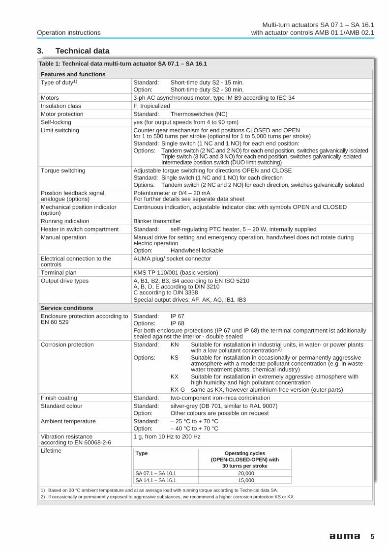
3. Technical data
5
Multi-turn actuators SA 07.1 – SA 16.1Operation instructions with actuator controls AMB 01.1/AMB 02.1
Features and functionsType of duty1) Standard: Short-time duty S2 - 15 min.
Option: Short-time duty S2 - 30 min.Motors 3-ph AC asynchronous motor, type IM B9 according to IEC 34Insulation class F, tropicalizedMotor protection Standard: Thermoswitches (NC)Self-locking yes (for output speeds from 4 to 90 rpm)Limit switching Counter gear mechanism for end positions CLOSED and OPEN
for 1 to 500 turns per stroke (optional for 1 to 5,000 turns per stroke)Standard: Single switch (1 NC and 1 NO) for each end position:Options: Tandem switch (2 NC and 2 NO) for each end position, switches galvanically isolated
Triple switch (3 NC and 3 NO) for each end position, switches galvanically isolatedIntermediate position switch (DUO limit switching)
Torque switching Adjustable torque switching for directions OPEN and CLOSEStandard: Single switch (1 NC and 1 NO) for each directionOptions: Tandem switch (2 NC and 2 NO) for each direction, switches galvanically isolated
Position feedback signal,analogue (options)
Potentiometer or 0/4 – 20 mAFor further details see separate data sheet
Mechanical position indicator(option)
Continuous indication, adjustable indicator disc with symbols OPEN and CLOSED
Running indication Blinker transmitterHeater in switch compartment Standard: self-regulating PTC heater, 5 – 20 W, internally suppliedManual operation Manual drive for setting and emergency operation, handwheel does not rotate during
electric operationOption: Handwheel lockable
Electrical connection to thecontrols
AUMA plug/ socket connector
Terminal plan KMS TP 110/001 (basic version)Output drive types A, B1, B2, B3, B4 according to EN ISO 5210
A, B, D, E according to DIN 3210C according to DIN 3338Special output drives: AF, AK, AG, IB1, IB3
Service conditionsEnclosure protection according toEN 60 529
Standard: IP 67Options: IP 68For both enclosure protections (IP 67 und IP 68) the terminal compartment ist additionallysealed against the interior - double sealed
Corrosion protection Standard: KN Suitable for installation in industrial units, in water- or power plantswith a low pollutant concentration2)
Options: KS Suitable for installation in occasionally or permanently aggressiveatmosphere with a moderate pollutant concentration (e.g. in waste-water treatment plants, chemical industry)
KX Suitable for installation in extremely aggressive atmosphere withhigh humidity and high pollutant concentration
KX-G same as KX, however aluminium-free version (outer parts)Finish coating Standard: two-component iron-mica combinationStandard colour Standard: silver-grey (DB 701, similar to RAL 9007)
Option: Other colours are possible on requestAmbient temperature Standard: – 25 °C to + 70 °C
Option: – 40 °C to + 70 °CVibration resistanceaccording to EN 60068-2-6
1 g, from 10 Hz to 200 Hz
Lifetime
1) Based on 20 °C ambient temperature and at an average load with running torque according to Technical data SA.2) If occasionally or permanently exposed to aggressive substances, we recommend a higher corrosion protection KS or KX
Table 1: Technical data multi-turn actuator SA 07.1 – SA 16.1
Type Operating cycles(OPEN-CLOSED-OPEN) with
30 turns per strokeSA 07.1 – SA 10.1 20,000SA 14.1 – SA 16.1 15,000

6
Multi-turn actuators SA 07.1 – SA 16.1with actuator controls AMB 01.1/AMB 02.1 Operation instructions
Other informationEC directives Electromagnetic Compatibility (EMC): (89/336/EEC)
Low Voltage Directive: (73/23/EEC)Machinery Directive: (98/37/EC)
Reference documents Product description “Electric multi-turn actuators SA”Dimension sheets SAElectrical data sheets SATechnical data sheet SA
Supply voltage Refer to name plateMotor controls reversingcontactors:
mechanical, electrically interlocked, max. 690 V AC, max. 7.5 kW
Control voltage Standard: 230 V AC from internal power supply unit, also available for input signalsOPEN-STOP-CLOSE/ OPEN-CLOSE and for external indication lights(P max = 2.5 W)
Option: 115 V AC from internal power supply unitBinary inputs(input signals)
Nominal voltage:
Standard: OPEN-STOP-CLOSE, EMERGENCY-STOPOption: OPEN-CLOSE, EMERGENCY-STOPStandard: 230 – 240 V AC from internal power supply unit (non potential-free)Option: 24 V DC externally supplied (potential-free via relay)
Binary outputs Standard: End position OPEN/ end position CLOSED (non potential-free)Option: End position OPEN / end position CLOSED (potential-free) in combination
with tandem limit switches in multi-turn actuator.Selector switch LOCAL/ selector switch REMOTE (potential-free)
Relay outputs(potential-free)
Version B01:without relay board (see binary outputs)Version B02:Thermoswitch or overload relay tripped (NO contact)Signal: Torque switch tripped in mid-travel (change-over contact).Version B03:see binary outputsVersion B04:Thermoswitch or overload relay tripped (NO contact)Signal: Torque switch tripped in mid-travel (change-over contact).
Local controls Standard: Selector switch LOCAL-OFF-REMOTE, lockablePush-buttons OPEN-STOP-CLOSE
Option: Push-buttons OPEN-CLOSE, EMERGENCY-STOPIndication lights end position OPEN, FAULT1), end position CLOSED
Enclosure protection Same as actuatorTemperature range Same as actuatorElectrical connection Standard: AUMA plug/socket connector with screw type connectionThreads for cable glands Standard: Metric thread
Options: Pg thread, NPT thread, G thread1) Only in conjunction with version BX02 and BX04
Table 2: Technical data actuator controls AMB 01.1/AMB 02.1

4. Additional information to the wiring diagram legend
Information A: Change-over switch S9 for changing the type of seating (see subclause19.2, page 23).
Information B: Self-retaining in local operation can be cancelled by cutting the link B3 (seesubclause 19.3, page 24).
Information C: Plug-in link for operation mode REMOTE (see subclause 19.4, page 24).
Information E: The control voltage is 115 V or 230 V AC (according to order) and must onlybe switched via potential-free contacts.End position signal: 115 V or 230 V AC, max. 2.5 W.
Information F: Instead of a link, an EMERGENCY switch with NC contact can be used.
Connections XK 49 and XK 50 carry control voltage (115 or230 V AC) and must only be opened via the potential-freecontact.
Information G: (Versions B02 and B04 only)Plug-in link for potential-free feedback (see subclause 19.6, page 25).
5. Transport and storage .Transport to place of installation in sturdy packing..Do not attach ropes or hooks to the handwheel for the purpose of lifting byhoist.. If multi-turn actuator is mounted on valve, attach ropes or hooks for thepurpose of lifting by hoist to valve and not to multi-turn actuator..Store in well-ventilated, dry room..Protect against floor dampness by storage on a shelf or on a woodenpallet..Cover to protect against dust and dirt..Apply suitable corrosion protection agent to bright surfaces.
If multi-turn actuators are to be stored for a long time (more than 6 months),the following points must be observed additionally:
.Prior to storage: Protect bright surfaces, in particular the output drive partsand mounting surface, with long-term corrosion protection agent..Check for corrosion approximately every 6 months. If first signs ofcorrosion show, apply new corrosion protection.
After mounting, connect actuator immediately to electrical system, so thatcondensation is prevented by the heater.
6. Packaging Our products are protected by special packaging for the transport ex works.The packaging consists of environmentally friendly materials which caneasily be separated and recycled.For the disposal of the packaging material we recommend recycling andcollection centres.We use the following packaging materials: wood, cardboard, paper and PEfoil.
7
Multi-turn actuators SA 07.1 – SA 16.1Operation instructions with actuator controls AMB 01.1/AMB 02.1

7. Mounting to valve/ gearbox .Prior to mounting the actuator must be checked fordamage. Damaged parts must be replaced by originalspare parts..After mounting to valve/ gearbox, touch up any possibledamage to paint finish.
Mounting is most easily done with the valve shaft/gearbox shaft pointingvertically upward. But mounting can be done in any other position as well.The multi-turn actuator leaves the factory in position CLOSED (limit switchCLOSED tripped).
.Check if mounting flange fits the valve/ gearbox.
Spigot at flanges should be loose fit!
The output drive types B1, B2, B3 or B4 (figure A) are delivered with boreand keyway (usually according to ISO 5210).
For output drive type A (figure B-1), the internal thread of the stem nut mustmatch the thread of the valve stem. If not ordered explicitly with thread, thestem nut is unbored or with pilot bore when delivered. For finish machiningof stem nut refer to next page..Check whether bore and keyway match the input shaft of valve/gearbox..Thoroughly degrease mounting faces at multi-turn actuator and valve/
gearbox..Apply a small quantity of grease to input shaft of valve/gearbox..Place actuator on valve/ gearbox and fasten. Fasten bolts (at leastquality 8.8, refer to table 3) evenly crosswise.
8
Multi-turn actuators SA 07.1 – SA 16.1with actuator controls AMB 01.1/AMB 02.1 Operation instructions
Figure AOutput drive type B1/B2
Plug sleeveOutput drive type B3/B4
Bore with keyway
Strength class 8.8 T A (Nm)M 8 25M 10 50M 12 87M 16 220M 20 420
Table 3: Fastening torque for bolts

Finish machining of stem nut (output drive type A):
The output drive flange does not have to be removed from the actuator.
.Remove spigot ring (80.2, figure B-1) from mounting flange..Take off stem nut (80.3) together with thrust bearing (80.01) and thrustbearing races (80.02)..Remove thrust bearing and thrust bearing races from stem nut..Drill and bore stem nut and cut thread.When fixing in the chuck, make sure stem nut runs true!.Clean the machined stem nut..Apply ball bearing grease to thrust bearing and races, then place them onstem nut..Re-insert stem nut with thrust bearings into the mounting flange. Ensurethat dogs are placed correctly in the slots of the hollow shaft..Screw in spigot ring until it is firm against the shoulder..Press Lithium soap EP multi-purpose grease on mineral oil base,quantities see table, into the grease nipple with a grease gun:
Protection tube for rising valve stem.Protection tubes may be supplied loose. Seal thread with hemp, Teflontape or thread sealing material..Screw protection tube (1) into thread (figure B-2) and tighten it firmly..For corrosion protection KS/ KX, push down the seal (2) to the housing..Check, whether cap (3) is available and without damage.
9
Multi-turn actuators SA 07.1 – SA 16.1Operation instructions with actuator controls AMB 01.1/AMB 02.1
Figure B-2: Protection tube for rising valve stem
3
1
2
Outputdrive
A 07.2 A 10.2 A 14.2 A 16.2 A 25.2 A 30.2 A 35.2 A 40.2 A 48.2
Qty.1) 1.5 g 2 g 3 g 5 g 10 g 14 g 20 g 25 g 30 g1) For grease with a density ρ = 0.9 kg/dm³
Table 4: Grease quantities for output drive A
Figure B-1
80.3
80.2
Output drive type AStem nut
80.01/ 80.02

8. Manual operation The actuator may be operated manually for purposes of setting andcommissioning, and in case of motor failure or power failure.Manual operation is engaged by an internal change-over mechanism.
Engaging manual operation: .Lift change-over lever in the centre of the handwheel up to approx. 85°,while slightly turning the handwheel back and forth until manual driveengages (figure C).
Manual force is sufficient for operating the change-overlever. It is not necessary to use an extension. Excessiveforce may damage the change-over mechanism.
.Release change-over lever (should snap back into initial position by springaction, figure D), if necessary push it back manually.
Operating the change-over lever while the motor is running(figure E) can lead to increased wear at the change-overmechanism.
.Turn handwheel into desired direction (figure F).
Disengaging manualoperation:
Manual operation is automatically disengaged when motor is started again.The handwheel does not rotate during motor operation.
10
Multi-turn actuators SA 07.1 – SA 16.1with actuator controls AMB 01.1/AMB 02.1 Operation instructions
Figure DFigure C
Figure E FIgure F

9. Electrical connection Work on the electrical system or equipment must only becarried out by a skilled electrician himself or by speciallyinstructed personnel under the control and supervision ofsuch an electrician and in accordance with the applicableelectrical engineering rules.
9.1 Connection with AUMA plug/ socket connector
.Check whether type of current, supply voltage and frequency correspondto motor data (refer to name plate at motor)..Loosen bolts (50.01) (figure G-1) and remove plug cover..Loosen screws (51.01) and remove socket carrier (51.0) from plug cover(50.0).. Insert cable glands suitable for connecting cables.(The enclosure protection stated on the name plate is only ensured ifsuitable cable glands are used)..Seal cable entries which are not used with suitable plugs..Connect cables according to order related wiring diagram.The wiring diagram applicable to the actuator is attached to thehandwheel in a weather-proof bag, together with the operationinstructions. In case the wiring diagram is not available, it can be obtainedfrom AUMA (state commission no., refer to name plate) or downloadeddirectly from the Internet (www.auma.com).
A special parking frame (figure G-2) for protection against touching the barecontacts and against environmental influences is available.
11
Multi-turn actuators SA 07.1 – SA 16.1Operation instructions with actuator controls AMB 01.1/AMB 02.1
Figure G-1: Connection
50.0
50.01
51.0
51.01
Bild G-2: Parking frame (accessory)
Parking frame
Technical data Protective earth Control pinsContacts max. 1 (leading contact) 50 pins/socketsDesignation according to VDE 1 to 50Voltage max. – 250 VCurrent max. – 16 AType of customer connection Screw for ring lug ScrewsCross section max. 6 mm2 2.5 mm2
Material: Pin/socket carrier Polyamide PolyamideContacts Brass (Ms) Brass, tin plated or gold plated (option)
Table 5: Technical data AUMA plug/socket connector

9.2 Heater AUMA multi-turn actuators have a heater installed as standard. To preventcondensation, the heater must be connected.
9.3 Motor protection In order to protect against overheating and impermissibly high temperaturesat the actuator, thermoswitches are embedded in the motor winding. Thethermoswitch is tripped as soon as the max. permissible windingtemperature has been reached.
9.4 Remote position transmitter For the connection of remote position transmitters (potentiometer, RWG)screened cables must be used.
9.5 Fitting of the cover After connection:
.After completion of the power supply connection, insert the socket carrier(51.0) into the plug cover (50.0) and fasten it with screws (51.01)..Clean sealing faces at the plug cover and the housing..Check whether O-ring is in good condition..Apply a thin film of non-acidic grease (e.g. Vaseline) to the sealing faces..Replace plug cover (50.0) and fasten bolts evenly crosswise..Fasten cable glands with the specified torque to ensure the requiredenclosure protection.
12
Multi-turn actuators SA 07.1 – SA 16.1with actuator controls AMB 01.1/AMB 02.1 Operation instructions

10. Opening the switchcompartment
To be able to make the following settings (clause 11. to 17.) the switchcompartment must be opened and, if installed, the indicator disc must beremoved.
These settings are only valid for “clockwise closing”, i.e. driven shaft turnsclockwise to close the valve.
Work on the electrical system or equipment must only becarried out by a skilled electrician himself or by speciallyinstructed personnel under the control and supervision ofsuch an electrician and in accordance with the applicableelectrical engineering rules.
10.1 Removal of the switch compartment cover
.Remove 4 bolts and take off the cover at the switch compartment(figure H) .
10.2 Pulling off the indicator disc (option)
. If installed, pull off indicator disc (figure J). Open end spanner(approx. 14 mm) may be used as lever.
13
Multi-turn actuators SA 07.1 – SA 16.1Operation instructions with actuator controls AMB 01.1/AMB 02.1
Figure H-2: Cover without indicatorglass
DSR
WDR
Figure J: Pulling off the indicator disc
Indicator disc
Figure H-1: Cover with indicator glass
Bolts

11. Setting of the limit switching
11.1 Setting for end position CLOSED (black section)
.Turn handwheel clockwise until valve is closed..After having reached the end position, turn back handwheel approximately1/2 a turn (overrun). During test run (page 17) check overrun and, ifnecessary, correct setting of the limit switching..Press down and turn setting spindle A (figure K-1) with screw driver(5 mm) in direction of arrow, thereby observe pointer B.While a ratchet is felt and heard, the pointer B moves 90° every time.When pointer B is 90° from mark C, continue turning slowly. When pointerB has reached the mark C, stop turning and release setting spindle. If youoverride the tripping point inadvertently (ratchet is heard after the pointerhas snapped), continue turning the setting spindle in the same directionand repeat setting process.
11.2 Setting for end position OPEN (white section)
.Turn handwheel counterclockwise until valve is open, then turn backapproximately 1/2 a turn..Press down and turn setting spindle D (figure K-1) with screw driver(5 mm) in direction of arrow, thereby observe pointer E.While a ratchet is felt and heard, the pointer E moves 90° every time.When pointer E is 90° from mark F, continue turning slowly. When pointerE has reached the mark F, stop turning and release setting spindle. If youoverride the tripping point inadvertently (ratchet is heard after the pointerhas snapped), continue turning the setting spindle in the same directionand repeat setting process.
11.3 Checking the switches The red test buttons T and P (figure K-1) serve for operating the limitswitches manually.
.Turning T in direction of the arrow LSC (WSR) triggers limit switch CLOSED..Turning P in direction of the arrow LSO (WÖL) triggers limit switch OPEN.
14
Multi-turn actuators SA 07.1 – SA 16.1with actuator controls AMB 01.1/AMB 02.1 Operation instructions
Figure K-1: Control unit
A
T
B
C
D
P
E
F

12. Setting of the DUO limit switching (option)
Any application can be switched on or off via the two intermediate positionswitches.
For setting, the switching point (intermediate position) mustbe approached from the same direction as afterwards inelectrical operation.
12.1 Setting for direction CLOSE (black section)
.Move valve to desired intermediate position..Press down and turn setting spindle G (figure K-2) with screw driver(5 mm) in direction of arrow, thereby observe pointer H.While a ratchet is felt and heard, the pointer H moves 90° every time.When pointer H is 90° from mark C, continue turning slowly. When pointerH has reached the mark C, stop turning and release setting spindle. If youoverride the tripping point inadvertently (ratchet is heard after the pointerhas snapped), continue turning the setting spindle in the same directionand repeat setting process.
12.2 Setting for direction OPEN (white section)
.Move valve to desired intermediate position..Press down and turn setting spindle K (figure K-2) with screw driver(5 mm) in direction of arrow, thereby observe pointer L.While a ratchet is felt and heard, the pointer L moves 90° every time.When pointer L is 90° from mark F, continue turning slowly. When pointerL has reached the mark F, stop turning and release setting spindle. If youoverride the tripping point inadvertently (ratchet is heard after the pointerhas snapped), continue turning the setting spindle in the same directionand repeat setting process.
15
Multi-turn actuators SA 07.1 – SA 16.1Operation instructions with actuator controls AMB 01.1/AMB 02.1
Figure K-2: Control unit
G
T
H
C
K
P
E
F

13. Setting of the torque switching
13.1 Setting .The set torque must suit the valve!.This setting should only be changed with the consent of
the valve manufacturer!
.Loosen both lock screws O at the torque dial (figure L).
.Turn torque dial P to set it to the required torque (1 da Nm = 10 Nm).Example:Figure J shows the following setting:3.5 da Nm = 35 Nm for direction CLOSE4.5 da Nm = 45 Nm for direction OPEN
.Tighten lock screws O again
.The torque switches can also be operated in manualoperation.
.The torque switching acts as overload protection over fulltravel, also when stopping in the end positions by limitswitching.
13.2 Checking the switches for torque and DUO limit switching
The red test buttons T and P (figure K-2) serve for operating the torqueswitches manually:
.Turning T in direction of the arrow TSC (DSR) triggers torqueswitch CLOSED.
.Turning P in direction of the arrow TSO (DÖL) triggers torqueswitch OPEN.
. If a DUO limit switching (optional) is installed in the actuator, theintermediate position switches will be operated at the same time.
16
Multi-turn actuators SA 07.1 – SA 16.1with actuator controls AMB 01.1/AMB 02.1 Operation instructions
P OO P
Setting CLOSED Setting OPEN
Figure L: Torque switching heads

14. Test run
14.1 Check direction of rotation This check is only required for multi-turn actuators with 3-ph AC motor.
. If provided, place indicator disc on shaft.The direction of rotation of the indicator disc (figure M-1) indicates thedirection of rotation of the output drive.. If there is no indicator disc, the direction of rotation can also be observedon the hollow shaft. To this end, remove screw plug (no. 27) (figure M-2).
.Move actuator manually to intermediate position or to sufficient distancefrom end position..Set selector switch to local control (I)(figure M-3).
.Switch on the voltage supply..Operate push-button CLOSE (figure M-4) and observe the direction ofrotation:
If the direction of rotation is wrong switch off immediatelywith push-button “Stop” (figure M-5) or by turning both testbuttons T and P (figure K-2) simultaneously in any direction.Correct phase sequence at motor connection. Repeat test run.
17
Multi-turn actuators SA 07.1 – SA 16.1Operation instructions with actuator controls AMB 01.1/AMB 02.1
Figure M-1: Indicator disc
CLOSE OPEN
Figure M-2: Opening the hollow shaft
27
S1/S2
Figure M-3: Selector switch on local controls
Figure M-5: Push-button STOPFigure M-4 Push-button CLOSE
Direction of rotation of the indicator disc:counterclockwise correctDirection of rotation of the hollow shaft:clockwise correct
Table 6:

14.2 Check the setting of the limit switching
.Move actuator manually into both end positions of the valve..Check whether limit switching is set correctly. Hereby observe that theappropriate switch is tripped in each end position and released again afterthe direction of rotation is changed. If this is not the case, the limitswitching must first be set, as described from page 14.
14.3 Check whether type of seating is set correctly
The valve manufacturer states whether switching off in the end positionCLOSED should be by limit seating or torque seating..Checking the setting: see page 23, clause 19.
If no other options (clauses 15. to 17.) require setting:.Close switch compartment (see page 22, clause 18.).
15. Setting of the potentiometer (option)
– For remote indication –
.Move valve to end position CLOSED.. If installed, pull off indicator disc..Turn potentiometer (E2) clockwise until stop is felt.End position CLOSED corresponds to 0 %, end position OPEN to 100 %..Turn potentiometer (E2) slightly back from the stop.
Due to the ratio of the reduction gearings for the positiontransmitter the complete resistance range is not alwaysutilized for the whole travel. Therefore an external possibilityfor adjustment (setting potentiometer) must be provided.
.Perform fine-tuning of the zero point at external setting potentiometer (forremote indication).
18
Multi-turn actuators SA 07.1 – SA 16.1with actuator controls AMB 01.1/AMB 02.1 Operation instructions
Figure N: Control unit
E2

16. Setting of electronic position transmitter RWG (option)
– For remote indication or external control –
After mounting the multi-turn actuator to the valve, check setting bymeasuring the output current (see subclause 16.1 or 16.2) and re-adjust, ifnecessary.
The position transmitter board (figure P-1) is located under the cover plate(figure P-2).
19
Multi-turn actuators SA 07.1 – SA 16.1Operation instructions with actuator controls AMB 01.1/AMB 02.1
Wiring diagrams BSP. . . KMS TP_ _ 4 / _ _ _
3-/ 4-wire system
BSP. . . KMS TP _ 4 _ / _ _ _BSP. . . KMS TP _ 5 _ / _ _ _
2-wire systemOutput current Ia 0 – 20 mA, 4 – 20 mA 4 – 20 mAPowersupply
Uv24 V DC, ± 15 %
smoothed14 V DC + (I x RB),
max. 30 VMax.current input
I 24 mA at 20 mAoutput current
20 mA
Max. load RB 600 Ω (Uv - 14 V) / 20 mA
Table 7: Technical data RWG 4020
Figure P-1: Position transmitter board

16.1 Setting for 2-wire system 4 – 20 mA and 3- /4-wire system 0 – 20 mA
.Connect voltage for electronic position transmitter..Move valve to end position CLOSED .. If installed, pull off indicator disc..Connect ammeter for 0 – 20 mA to measuring points (figure P-2).
The circuit (external load) must be connected (max. loadRB), or the appropriate poles at the terminals (refer toterminal plan) must be linked, otherwise no value can bemeasured.
.Turn potentiometer (E2) clockwise until stop is felt..Turn potentiometer (E2) slightly back from the stop.
.Turn potentiometer “0” clockwise until output current starts to increase..Turn potentiometer “0” back until the following value is reached:for 3-/4-wire system approx. 0.1 mAfor 2-wire system: approx. 4.1 mA.This ensures that the signal remains above the dead and live zero point..Move valve to end position OPEN..Set potentiometer “max.” to end value 20 mA..Approach end position CLOSED anew and check minimum value (0.1 mAor 4.1 mA). If necessary, correct the setting.
If the maximum value can not be reached, the selection ofthe reduction gearing must be checked.
20
Multi-turn actuators SA 07.1 – SA 16.1with actuator controls AMB 01.1/AMB 02.1 Operation instructions
Figure P-2 “0” (0/4 mA) “max.” (20 mA)
Measuring point(+)0/4 – 20 mA
Measuring point(–)0/4 – 20 mA
Cover plate
E2

16.2 Setting for 3- / 4- wire system 4 – 20 mA.Connect voltage for electronic position transmitter..Move valve to end position CLOSED.. If installed, pull off indicator disc..Connect ammeter for 0 – 20 mA to measuring points (figure P-2).
The circuit (external load) must be connected (max.load R B), or the appropriate poles at the terminals (refer toterminal plan) must be linked, otherwise no value can bemeasured.
.Turn potentiometer (E2) clockwise until stop is felt..Turn potentiometer (E2) slightly back from the stop.
.Turn potentiometer “0” clockwise until output current starts to increase..Turn back potentiometer “0” until a residual current of approx. 0.1 mA isreached..Move valve to end position OPEN..Set potentiometer “max.” to end value 16 mA..Move valve to end position CLOSED..Set potentiometer “max.” from 0.1 mA to initial value 4 mA.This results in a simultaneous shift of the end value by 4 mA, so that therange is now 4 – 20 mA..Approach both end positions anew and check setting. If necessary, correctthe setting.
If the maximum value can not be reached, the selection ofthe reduction gearing must be checked.
21
Multi-turn actuators SA 07.1 – SA 16.1Operation instructions with actuator controls AMB 01.1/AMB 02.1
Figure P-2
Cover plate
Measuring point(+)0/4 – 20 mA
“0” (0/4 mA) “max.” (20 mA)
E2
Measuring point(–)0/4 mA – 20 mA

17. Setting of the mechanical position indicator (option)
A suitable reduction gearing was installed in our works. If the turns perstroke are changed at a later date, the reduction gearing may have to beexchanged, too.
.Place indicator disc on shaft..Move valve to end position CLOSED..Turn lower indicator disc (figure Q-1) until symbol CLOSED is inalignment with the mark on the cover (figure Q-2)..Move actuator to end position OPEN..Hold lower indicator disc CLOSED in position and turn upper disc withsymbol OPEN until it is in alignment with the mark on the cover.
Indicator disc rotates approximately 180° at full travel from OPEN toCLOSED or vice versa.
18. Closing the switch compartment
.Clean sealing faces of housing and cover.Check whether O-ring is in good condition..Apply a thin film of non-acidic grease to the sealing faces..Replace cover on switch compartment and fasten bolts evenly crosswise.
Touch up possible defects to paint finish aftercommissioning.
22
Multi-turn actuators SA 07.1 – SA 16.1with actuator controls AMB 01.1/AMB 02.1 Operation instructions
Indicator disc
Figure Q-1: Figure Q-2:
Mark

19. Controls AUMA MATIC BASIC
19.1 Removal of the local controls The local controls must only be removed when settings at the controls haveto be performed (subclause 19.2 to 19.4).
.Remove local controls (figure R-1). The signal and control board islocated under the local controls (figure R-2).
19.2 Setting the type of seating in the end position CLOSED
The valve manufacturer states whether switching off in the end positionCLOSED should be by limit seating or torque seating.
This setting should only be changed with the consent of thevalve manufacturer.
In case the type of seating is to be changed at a later date:
Limit seating: .Set change-over switch S9 (figure R-2) to position .
Actuator switches off in end position CLOSED via limit switch WSR (LSC)(S3), see wiring diagram. The tripping of the torque switch DSR (TSC) (S1)in mid-travel or in the end position switches off the actuator and causes afault signal.
Torque seating:
.Set change-over switch S9 (figure R-2) to position .
Actuator switches off in the end position CLOSED by torque switch DSR(TSC) (S1), see wiring diagram. The limit switch WSR (LSC) (S3) is used forsignalising. It needs to be set in such a way that it is tripped shortly beforereaching the end position CLOSED.If the torque switch trips before the limit switch, the actuator is switched offand a fault signal is given.
23
Multi-turn actuators SA 07.1 – SA 16.1Operation instructions with actuator controls AMB 01.1/AMB 02.1
M
(1) (3)
(2)
F1 F2
Figure R-2: Signal and control board
S9(Switch)
B3(Link)
Figure R-1: Local controls
Local controls
Cover
M

19.3 Push-to-run operation or self-retaining in selector switch position LOCAL
Push-to-run operation or self-retaining is set in the factory.A change at a later date is only possible by cutting the link B3(see figure R-2).
.Remove local controls (figure R-1). The signal and control board is locatedunder the local controls (figure R-2).Link cut: Push-to-run operation LOCAL.Link closed: Self-retaining LOCAL.
19.4 Push-to-run operation or self-retaining in selector switch position REMOTE
Push-to-run operation or self-retaining is set in the factory.If the operation mode is to be changed at a later date:
.Loosen the three screws (1-3) and remove signal and control board(figure R-2), but do not interrupt plug-in connections..Move red plug-in link (figure S) on wiring board.
.Fit signal and control board (figure R-2) again.
19.5 Fitting the local controls .Clean sealing faces of housing and cover.Check whether O-ring is in good condition..Apply a thin film of non-acidic grease to the sealing faces..Place local controls and fasten the bolts evenly crosswise.
24
Multi-turn actuators SA 07.1 – SA 16.1with actuator controls AMB 01.1/AMB 02.1 Operation instructions
Plug-in link on B1 Self-retaining REMOTE
B2
B1Push-to-run operation REMOTE
Plug-in link on B2 (Maintained contact REMOTE)
Selbsth.FernPuls contactB1
B2 Dauerbefehl FernMaintained contact
Figure S: Wiring board
Plug-in link

19.6 Settings on relay board for potential-free feedback (option)
Only valid for versions (B02 and B04) with relays K6, K7, K8 on relay board.
.Remove cover (figure R-1, page 23) of AUMA MATIC BASIC..Assign the required functions to the terminals XK ... of the customerconnection (see wiring diagram) with the red plug-in links, according totable 8..Clean sealing faces of housing and cover.Check whether O-ring is in good condition..Apply a thin film of non-acidic grease to the sealing faces..Replace cover and fasten bolts evenly crosswise.
25
Multi-turn actuators SA 07.1 – SA 16.1Operation instructions with actuator controls AMB 01.1/AMB 02.1
K6 K7K8 K6 K7K8
Figure T1: Relay board version B02 Figure T2: Relay board version B04
Plug-in links
Function(Signal on terminal XK ... 1) active, if the function is correct)
Signalavailable onterminal 1)
Link
Torque switch tripped in mid-travel and/ or thermoswitch or thermal overload relay tripped XK 16
No torque switch tripped in mid-travel XK 15
No thermoswitch or no thermal overload relay tripped XK 13
No torque switch tripped in mid-travel XK 15
Torque switch tripped in mid-travel XK 16
No function XK 13
No torque switch tripped in mid-travel XK 15
Torque switch tripped in mid-travel XK 16
No thermoswitch or no thermal overload relay tripped XK 13
No torque switch tripped in mid-travel XK 15
Torque switch tripped in mid-travel XK 16
Thermoswitch or thermal overload relay tripped XK 13
Torque switch tripped in mid-travel XK 16
No torque switch tripped in mid-travel XK 15
No function XK 13
Common link to XK 141) refer to order-related wiring diagram BSP … KMS TP ...
Table 8

20. Fuses .Fuses (figures U1 and U2) are accessible after removal ofthe local controls (refer to page 23, figure R-1)..When exchanging the fuses, only fuses with the samevalues must be used.
F1/ F2: Primary fuses power supply unit
F3: Internal 24 V DC supplyF4: Internal 24 V AC supply (optional: 115 V AC);
Heater, tripping device for PTC thermistors, control reversingcontactors
F5: Automatic reset fuse as short-circuit protection (see wiringdiagram) for external 24 V DC supply for customer
.After exchanging the fuses screw local controls back on again(refer also to subclause 19.5).
26
Multi-turn actuators SA 07.1 – SA 16.1with actuator controls AMB 01.1/AMB 02.1 Operation instructions
Figure U2: Fuses on power supply board
F3 F4 F5
Figure U1: Fuses on signal and control board
1F2
1F1
G-fuses:(Figure U1 and U2)
F 1/F 2(Board A1,
refer to wiring diagram)
F 3/F4*)
(Board A2,refer to wiring diagram)
F 5(Board A2,
refer to wiring diagram)
Size 6.3 x 32 mm 5 x 20 mm 5 x 20 mm
Control voltagePower supply unit 115 V
1 A T; 500 V 315 mA T 250 mA T
Control voltagePower supply unit 230 V
1 A T; 500 V 160 mA T 160 mA T
*) according to IEC 60127-2/III
Table 9

21. Maintenance After commissioning, check multi-turn actuator for damage to paint finish.Do a thorough touch-up to prevent corrosion. Original paint in smallquantities can be supplied by AUMA.
AUMA multi-turn actuators require very little maintenance.Precondition for reliable service is correct commissioning.
Seals made of elastomers are subject to aging and must therefore regularlybe checked and, if necessary, exchanged.
It is also very important that the O-rings at the covers are placed correctlyand cable glands fastened firmly to prevent ingress of dirt or water.
We recommend additionally:
. If operated seldom, perform a test run about every 6 months. This ensuresthat the actuator is always ready to operate..Approximately six months after commissioning and then every year checkbolts between actuator and valve/gearbox for tightness. If required, tightenapplying the torques given in table 3, page 8..For multi-turn actuators with output drive type A: at intervals of approx. 6months from commissioning press in Lithium soap EP multi-purposegrease on mineral oil base at the grease nipple with grease gun (quantitysee table 4, page 9).
22. Lubrication .The gear housing is filled with lubricant in the factory..A grease change is recommended after the following operation time:
. If operated seldom after 10 – 12 years. If operated frequently after 6 – 8 years
Lubrication of the valve stem must be done separately.
23. Disposal and recyclingAUMA actuators have an extremely long lifetime. However, there will come atime when you have to replace them.Our actuators have a modular design and may therefore easily bedisassembled, separated and sorted according to materials, i.e.:
.electronic scrap.various metals.plastics.greases and oils
The following generally applies:.Collect greases and oils during disassembly. As a rule, these substancesare hazardous to water and must not be released into the environment..See disassembled material to a sound disposal or to separate recyclingaccording to materials..Observe the national regulations for waste disposal.
24. Service AUMA offers extensive services such as maintenance and inspection foractuators. Addresses of AUMA offices and representatives can be found onpage 36 and on the Internet (www.auma.com).
27
Multi-turn actuators SA 07.1 – SA 16.1Operation instructions with actuator controls AMB 01.1/AMB 02.1

Notes
28
Multi-turn actuators SA 07.1 – SA 16.1with actuator controls AMB 01.1/AMB 02.1 Operation instructions

Notes
29
Multi-turn actuators SA 07.1 – SA 16.1Operation instructions with actuator controls AMB 01.1/AMB 02.1

25. Spare parts list multi-turn actuator SA 07.1 – SA 16.1
30
Multi-turn actuators SA 07.1 – SA 16.1with actuator controls AMB 01.1/AMB 02.1 Operation instructions
SA
07.1
–S
A14
.1S
AR
07.1
–S
AR
14.1
SA
16.1
SA
R16
.1
79.0 S2
S2
S2
79.0
S2
70.0
S1
/ S2
70.1
51.0
54.0
53.0
56.0
57.0
52.0
20.0
59.0 49
.0
S2
S2
24
25.0
019
020
24.0
/ 23.
022
.0
50.0 55
.0
58.0
27 S1
/ S2
S1
/ S2 39
151.
0
160.
1
160.
2
S1
/ S2
S2
19.0
17.0
5.7
5.12
S1
/ S2
156.
0
15.0
105.
01.
0
60.0
61.0
106.
010
0
107
1805
3
6
3.0
S2
S2
2.0
S2
5.32
B1
/ CA
DB
3/ B
4/ E
5.0
5.8 5.
37
152.
1
152.
2
153.
2
153.
1
153.
3
153.
0
153.
5
9.0
10.0
S2
S2
30.0
155.
0
S2
80.0
01
80.0
01
80.3
80.0
90.0
01
90.0
01
90.0
85.0
85.0
01
85.0
01
14
012
Sam
ple
nam
epl
ate
-A
ctua
tor
type
-C
omm
issi
onnu
mbe
r-
Wor
ksnu
mbe
r-
Type
ofen
clos
ure
prot
ectio
nan
dou
tput
spee
dTo
rque
rang
ein
CLO
SE
/OP
EN
-Lu
bric
ant
-Te
mpe
ratu
rera
nge

31
Multi-turn actuators SA 07.1 – SA 16.1Operation instructions with actuator controls AMB 01.1/AMB 02.1
No. Type Designation
012 E Notched pin
019 E Cheese head screw
020 E Clamping washer
053 E Countersunk screw
1.0 B Housing assly.
2.0 B Flange, bottom assly.
3.0 B Hollow shaft assly. (without worm wheel)
5.0 B Worm shaft assly.
5.12 E Grub screw
5.32 E Coupling pin
5.37 B Pull rod assly.
5.7 E Motor coupling
5.8 B Manual drive coupling assly.
6 E Worm wheel
9.0 B Planetary gear for manual drive assly.
10.0 B Retaining flange assly.
14 E Change-over lever
15.0 B Cover for switch compartment assly.
17.0 B Torque lever assly.
18 E Gear segment
19.0 B Crown wheel assly.
20.0 B Swing lever assly.
22.0 B Drive pinion II for torque switching assly.
23.0 B Drive wheel for limit switching assly.
24 E Drive wheel for limit switching
24.0 B Intermediate wheel for limit switching assly.
25.0 E Locking plate
27 E Screw plug
30.0 B Handwheel with ball handle assly.
39 E Screw plug
49.0 1) B Motor plug, socket assly.
50.0 B Cover assly.
51.0 B Socket carrier assly. (with sockets)
52.0 B Pin carrier (without pins)
53.0 B Socket for control
54.0 B Socket for motor
55.0 B Socket for protective earth
56.0 B Pin for control
57.0 B Pin for motor
No. Type Designation
58.0 B Wire for protective earth
59.0 1) BPin for motor and thermoswitchin motor plug
60.0 BControl unit assly. (but without torque head,without switches)
61.0 B Torque switching head
70.0 B Motor
70.1 1) BMotor pin carrier(without pins)
79.0 2) B Planetary gearing for motor drive assly.
80.0 3) BOutput drive Form A assly.(without thread in stem nut)
80.0013 E Thrust bearing set
80.3 3) E Stem nut (without thread)
85.0 3) B Output drive B3
85.0013) E Snap ring
90.0 3) B Output drive D
90.0013) E Snap ring
100 BSwitch for limit / torque switching(including pins at wires)
105.0 BBlinker transmitter including pins at wires(without impulse disc and insulation plate)
106.0 B Stud bolt for switches
107 E Spacer
151.0 B Space heater
152.1 3) B Potentiometer (without slip clutch)
152.2 3) B Slip clutch for potentiometer
153.0 3) B RWG assly.
153.1 3) BPotentiometer for RWG(without slip clutch)
153.2 3) B Slip clutch for RWG
153.3 3) B Electronic board RWG
153.5 3) B Wires for RWG
155.0 3) B Reduction gearing
156.0 3) B Mechanical position indicator
160.1 3) E Protection tube (without cap)
160.2 3) E Cap for stem protection tube
S1 S Seal-kit, small
S2 S Seal-kit, large
Note:When placing orders for spare parts, please mention type of actuator and our commission number(refer to name plate).
1) SA 16.1 with output speeds 32 to 180 rpm without motor plug/socket assly.; motor directly wired to pin carrier (no. 52.0)2) Only required for some output speeds3) Not included in basic equipment

26. Spare parts list controls AUMA MATIC
32
Multi-turn actuators SA 07.1 – SA 16.1with actuator controls AMB 01.1/AMB 02.1 Operation instructions
50.0
54.0 51
.053.0
56.0
57.0
52.0
4.5
1.0
4.0
4.1
4.2
4.3
4.4
13.1
6.0
6.1
6.01
9.0
8.0
8.1
8.2
15.0
55.0
58.0
1.01
1.02
3.01
3.02
3.03
3.0
13.0
2.0
2.5
2.3
2.1
2.2
-C
ontr
ols
type
-C
omm
issi
onnu
mbe
r-
Wor
ksnu
mbe
r-
Term
inal
plan
actu
ator
-W
iring
diag
ram
-S
uppl
yvo
ltage
/enc
losu
repr
otec
tion
-C
ontr
olvo
ltage
Sam
ple
nam
epl
ate

33
Multi-turn actuators SA 07.1 – SA 16.1Operation instructions with actuator controls AMB 01.1/AMB 02.1
Note:When placing your order for spare parts, please mention type of the controls and our commission number(refer to name plate of controls).
No. Type Designation
1.0 E Housing
1.01 E Hexagon socket head cap screw
1.02 E Lock washer
2.0 B Cover local controls
2.1 B Switch knob
2.2 E Pad lock
2.3 E Face-plate for local controls
2.5 E Selector switch
3.0 B Signal and control board
3.01 E Primary fuse
3.02 E Fuse cover
3.03 E Bulb for indication light
4.0 B Contactors assly.
4.1 E Reversing contactors
4.2 E Carrier for contactors
4.3 E Socket carrier (with sockets)
4.4 E Grub screw
4.5 E RC unit
6.0 B Power supply
No. Type Designation
6.1 B Mounting plate for power supply
6.01 S Secondary fuse
8.0 E not installed
8.1 not installed
8.2 not installed
9.0 B Relay board
13.0 B Wiring board
13.1 E Stud
15.0 B Cover assly.
50.0 B Plug cover assly.
51.0 B Socket carrier assly. (with sockets)
52.0 B Pin carrier (without pins)
53.0 B Socket for control
54.0 B Socket for motor
55.0 B Socket for protective earth
56.0 B Pin for control
57.0 B Pin for motor
58.0 B Protective earth
S S Seal-kit

27. Declaration of Conformity and Declaration of Incorporation
34
Multi-turn actuators SA 07.1 – SA 16.1with actuator controls AMB 01.1/AMB 02.1 Operation instructions

35
Multi-turn actuators SA 07.1 – SA 16.1Operation instructions with actuator controls AMB 01.1/AMB 02.1
IndexCControl voltage 6Corrosion protection 7,27
DDeclaration of Conformity 34Declaration of Incorporation 34Direction of rotation 17Disposal and recycling 27DUO limit switching 15
EElectrical connection 11Electronic positiontransmitter RWG 19
2-wire system 203-/4-wire system 21
FFeedback 25Finish machining of stem nut 9Fuses 26
HHandwheel 10Heater 12
IIndicator disc 13,22Internet 35
LLimit switches 14Limit switching 14,15,18Local controls 6,23Lubrication 27
MMaintenance 4Manual operation 10Mechanical position indicator 22Motor protection 12Mounting to valve/ gearbox 8
NName plate 30,32
OOutput drive types 8
PPackaging 7Parking frame 11Position indicator 22Position transmitter RWG 19Potentiometer 18Protection tube 9Push-to-run operation 24
RRelay board 25Remote indication 18,19Remote positiontransmitter RWG 12,19
SSafety instructions 4Self-retaining 24Service 27Signal and control board 23Signals 25Spare parts list 30
Actuator 30Controls 32
Storage 7
TTechnical data 5Test run 17Thermal overload relay 25Thermoswitches 12,25Torque setting 16Transport 7Type of duty 5Type of seating 23
WWiring board 24
Information also availableon the Internet:
Terminal plan, inspection records and further actuator informationcan be downloaded directly from the internet by entering the order no.or comm no. (refer to name plate).Our homepage: http://www.auma.com

ISO 9001ISO 14001
Certificate Registration No.12 100 426912 104 4269
www.auma.com
AUMA Riester GmbH & Co. KGP. O. Box 1362D - 79373 Mü[email protected]
+49 (0)7631/809-0+49 (0)7631/809 250
+49 (0)711 / 34803 0+49 (0)711 / 34803 34
AUMA Riester GmbH & Co. KGP. O. Box 1151D - 73747 [email protected]
For detailed information about the AUMA products refer to the Internet:Y000.586/003/en/1.04
GermanyAUMA Riester GmbH & Co. KGWerk MüllheimDE-79373 MüllheimTel +49 7631 809 0Fax +49 7631 809 [email protected] Ostfildern-NellingenDE-73747 OstfildernTel +49 711 34803 - 0Fax +49 711 34803 - [email protected] MagdeburgDE-39167 NiederndodelebenTel +49 39204 759 - 0Fax +49 39204 759 - [email protected] KölnDE-50858 KölnTel +49 2234 20379 - 00Fax +49 2234 20379 - [email protected] BayernDE-85748 Garching-HochbrückTel +49 89 329885 - 0Fax +49 89 329885 - [email protected]üro Nord, Bereich SchiffbauDE-21079 HamburgTel +49 40 791 40285Fax +49 40 791 [email protected]üro Nord, Bereich IndustrieDE-29664 WalsrodeTel +49 5167 504Fax +49 5167 [email protected]üro OstDE-39167 NiederndodelebenTel +49 39204 75980Fax +49 39204 [email protected]üro WestDE-45549 SprockhövelTel +49 2339 9212 - 0Fax +49 2339 9212 - [email protected]üro Süd-WestDE-69488 BirkenauTel +49 6201 373149Fax +49 6201 [email protected]üro WürttembergDE-73747 OstfildernTel +49 711 34803 80Fax +49 711 34803 [email protected]üro BadenDE-76764 RheinzabernTel +49 7272 76 07 - 23Fax +49 7272 76 07 - [email protected]üro KraftwerkeDE-79373 MüllheimTel +49 7631 809 - 192Fax +49 7631 809 - [email protected]üro BayernDE-93356 Teugn/NiederbayernTel +49 9405 9410 24Fax +49 9405 9410 [email protected]
EuropeAUMA Armaturenantriebe GmbHAT-2512 TribuswinkelTel +43 2252 82540Fax +43 2252 [email protected] (Schweiz) AGCH-8965 BerikonTel +41 566 400945Fax +41 566 [email protected] Servopohony spol. s.r.o.CZ-10200 Praha 10Tel +420 272 700056Fax +420 272 [email protected] AUMATOR ABFI-02270 EspooTel +35 895 84022Fax +35 895 [email protected] FranceFR-95157 Taverny CédexTel +33 1 39327272Fax +33 1 [email protected] ACTUATORS Ltd.GB- Clevedon North Somerset BS21 6QHTel +44 1275 871141Fax +44 1275 [email protected] ITALIANA S.r.l.IT-20020 Lainate MilanoTel +39 0 2 9317911Fax +39 0 2 [email protected] BENELUX B.V.NL-2314 XT LeidenTel +31 71 581 40 40Fax +31 71 581 40 [email protected] Polska Sp. zo. o.PL-41-310 Dabrowa GórniczaTel +48 32 26156 68Fax +48 32 26148 [email protected] Priwody OOORU-123363 MoscowTel +7 095 787 78 22Fax +7 095 787 78 [email protected]ØNBECH & SØNNER A/SDK-2450 Copenhagen SVTel +45 3326 6300Fax +45 3326 [email protected] S.A.ES-28027 MadridTel +34 91 3717130Fax +34 91 [email protected]. G. Bellos & Co. O.E.GR-13671 Acharnai AthensTel +30 210 2409485Fax +30 210 [email protected] SØRUM A. S.NO-1301 SandvikaTel +47 67572600Fax +47 [email protected] SintraTel +351 2 1910 95 00Fax +351 2 1910 95 [email protected]
ERICHS ARMATUR ABSE-20039 MalmöTel +46 40 311550Fax +46 40 [email protected] Endüstri Kontrol Sistemieri Tic. Ltd.Sti.TR-06460 Övecler AnkaraTel +90 312 472 62 70Fax +90 312 472 62 [email protected]
North AmericaAUMA ACTUATORS INC.US-PA 15317 CanonsburgTel +1 724-743-AUMA (2862)Fax +1 [email protected] Inc.CA-L4N 5E9 Barrie OntarioTel +1 705 721-8246Fax +1 705 [email protected] DE MEXICO S. A. de C. V.MX-C.P. 02900 Mexico D.F.Tel +52 55 55 561 701Fax +52 55 53 563 [email protected]
South AmericaAUMA Chile Respresentative OfficeCL- La Reina Santiago de ChileTel +56 22 77 71 51Fax +56 22 77 84 [email protected] S. A.AR-C1140ABP Buenos AiresTel +54 11 4307 2141Fax +54 11 4307 [email protected] Termoindustrial Ltda.BR-13190-000 Monte Mor/ SP.Tel +55 19 3879 8735Fax +55 19 3879 [email protected] de Colombia Ltda.CO- Bogotá D.C.Tel +57 1 4 011 300Fax +57 1 4 131 [email protected] Procesos y Control AutomáticoEC- QuitoTel +593 2 292 0431Fax +593 2 292 [email protected] Latin America S. A.PE- San Isidro Lima 27Tel +511 222 1313Fax +511 222 [email protected] Inc.PR-00936-4153 San JuanTel +18 09 78 77 20 87 85Fax +18 09 78 77 31 72 [email protected] Maracaibo Edo, ZuliaTel +58 261 7 555 667Fax +58 261 7 532 [email protected]
AfricaAUMA South Africa (Pty) Ltd.ZA-1560 SpringsTel +27 11 3632880Fax +27 11 [email protected]
A.T.E.C.EG- CairoTel +20 2 3599680 - 3590861Fax +20 2 [email protected]
AsiaAUMA (India) Ltd.IN-560 058 BangaloreTel +91 80 8394655Fax +91 80 [email protected] JAPAN Co., Ltd.JP-210-0848 Kawasaki-ku, Kawasa -ki-shi KanagawaTel +81 44 329 1061Fax +81 44 366 [email protected] ACTUATORS (Singapore) Pte Ltd.SG-569551 SingaporeTel +65 6 4818750Fax +65 6 [email protected] Middle East Representative OfficeAE- SharjahTel +971 6 5746250Fax +971 6 [email protected] Beijing Representative OfficeCN-100029 BeijingTel +86 10 8225 3933Fax +86 10 8225 [email protected] CONTROLS Ltd.HK- Tsuen Wan, KowloonTel +852 2493 7726Fax +852 2416 [email protected] WOO Valve Control Co., Ltd.KR-153-803 Seoul KoreaTel +82 2 2113 1100Fax +82 2 2113 1088/[email protected] Eng. Company W. L. L.KW-22004 SalmiyahTel +965 4817448Fax +965 [email protected] TradingQA- DohaTel +974 4433 236Fax +974 4433 [email protected] Valves and Intertrade Corp. Ltd.TH-10120 Yannawa BangkokTel +66 2 2400656Fax +66 2 [email protected] Advance Enterprises Ltd.TW- TaipeiTel +886 2 27333530Fax +886 2 [email protected]
AustraliaBARRON GJM Pty. Ltd.AU-NSW 1570 ArtarmonTel +61 294361088Fax +61 [email protected]