electric circuits i dr. hassan ahmad
TRANSCRIPT
Electric Circuits I
Dr. Eng.
Hassan M. Ahmad [email protected], [email protected]
كــلــيـــة هندسة الحاسوب والمعلوماتية
Computer and Informatics Engineering
Faculty
Dr. H
assan A
hmad
2
Chapter 8 Second-Order Circuits
8.1 Examples of 2nd order RCL circuit
8.2 Finding Initial and Final Values
8.3 The source-free series RLC circuit
8.4 The source-free parallel RLC circuit
8.5 Step response of a series RLC circuit
8.6 Step response of a parallel RLC
9/23/2018 Dr. Eng. Hassan Ahmad Dr. H
assan A
hmad

8.1 Examples of 2nd order RCL circuit
A second-order circuit is characterized by a second-
order differential equation. It consists of resistors and
the equivalent of two energy storage elements.
Typical examples of second-order circuits:
(a) series RLC circuit,
(b) parallel RLC circuit,
(c) RL circuit,
(d) RC circuit.
3 9/23/2018 Dr. Eng. Hassan Ahmad Dr. H
assan A
hmad

8.2 Finding Initial and Final Values
The major problem in analysis of the second-order circuits is finding the
initial and final conditions on circuit variables: v(0), i(0), dv(0)∕dt, di(0)∕dt,
i(∞), and v(∞).
There are two key points to keep in mind in determining the initial conditions.
• First—we must carefully handle the polarity of voltage v(t) across the
capacitor and the direction of the current i(t) through the inductor.
• Second, keep in mind that the capacitor voltage is always continuous so
that
and the inductor current is always continuous so that
where denotes the time just before a switching event and is the
time just after the switching event, assuming that the switching event takes
place at t = 0.
4 9/23/2018 Dr. Eng. Hassan Ahmad
(0 ) (0 )v v
(0 ) (0 )i i
0t 0t
Dr. H
assan A
hmad
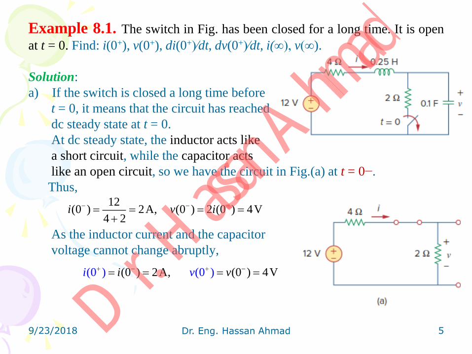
Example 8.1. The switch in Fig. has been closed for a long time. It is open
at t = 0. Find: i(0+), v(0+), di(0+)∕dt, dv(0+)∕dt, i(∞), v(∞).
Solution:
a) If the switch is closed a long time before
t = 0, it means that the circuit has reached
dc steady state at t = 0.
At dc steady state, the inductor acts like
a short circuit, while the capacitor acts
like an open circuit, so we have the circuit in Fig.(a) at t = 0−.
Thus,
As the inductor current and the capacitor
voltage cannot change abruptly,
9/23/2018 Dr. Eng. Hassan Ahmad 5
12(0 ) 2A, (0 ) 2 (0 ) 4V
4 2i v i
(0 ) 2A,(0 ) (0 ) (0 ) 4Vi vi v
Dr. H
assan A
hmad
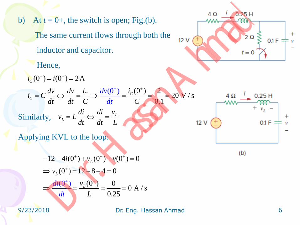
b) At t = 0+, the switch is open; Fig.(b).
The same current flows through both the
inductor and capacitor.
Hence,
Similarly,
Applying KVL to the loop:
9/23/2018 Dr. Eng. Hassan Ahmad 6
(0 ) (0 ) 2A
(0 ) 220 V /
0.
(s
1
0 )
C
C CC
i i
i idv dv
dt
dvi C
dt dt C C
LL
di di vv L
dt dt L
12 4 (0 ) (0 ) (0 ) 0
(0 ) 12 8 4 0
(0 ) 00 A / s
0.25
(0 )
L
L
Ldi
t
i v v
v
v
Ld
Dr. H
assan A
hmad

c) For t > 0, the circuit undergoes transience.
But as t → ∞, the circuit reaches steady
state again.
The inductor acts like a short circuit and
the capacitor like an open circuit, so that
the circuit in Fig.(b) becomes that shown
in Fig. (c), from which we have
9/23/2018 Dr. Eng. Hassan Ahmad 7
( ) 0A, ( ) 12Vi v
Dr. H
assan A
hmad
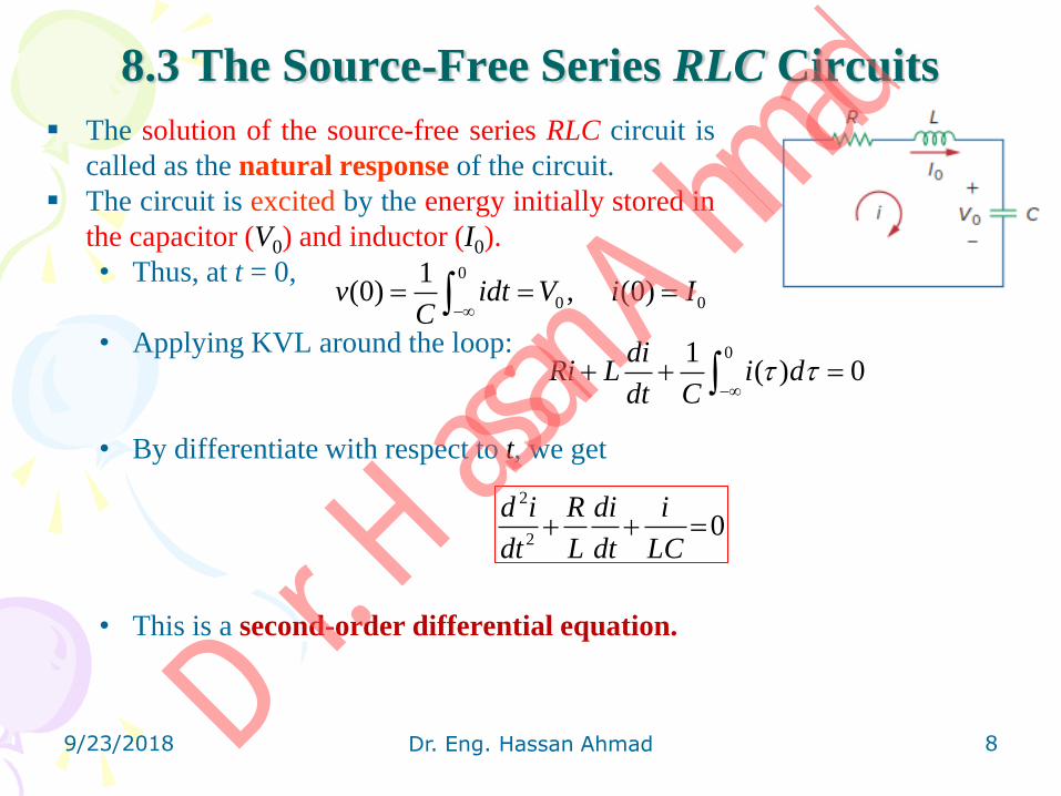
8.3 The Source-Free Series RLC Circuits
The solution of the source-free series RLC circuit is
called as the natural response of the circuit.
The circuit is excited by the energy initially stored in
the capacitor (V0) and inductor (I0).
• Thus, at t = 0,
• Applying KVL around the loop:
• By differentiate with respect to t, we get
• This is a second-order differential equation.
8 9/23/2018 Dr. Eng. Hassan Ahmad
0
0 0
1(0) , (0)v idt V i I
C
01( ) 0
diRi L i d
dt C
2
20
d i R di i
dt L dt LC
Dr. H
assan A
hmad
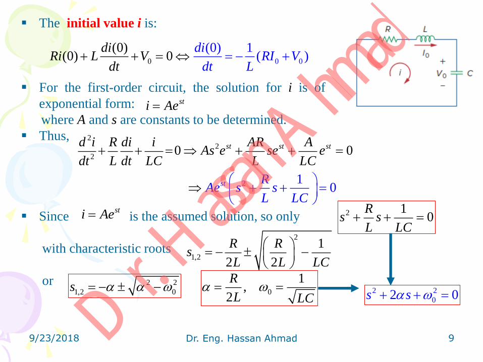
The initial value i is:
For the first-order circuit, the solution for i is of
exponential form:
where A and s are constants to be determined.
Thus,
Since is the assumed solution, so only
with characteristic roots
or
9 9/23/2018 Dr. Eng. Hassan Ahmad
0 00
(0 (0) 1( )
)(0) 0
diRI V
diRi L V
d dt Lt
sti Ae
22
2
2 1
0 0
0
st st s
st
td i R di i AR AAs e se e
dt L dt
R
LC L L
Ae s s
C
L LC
sti Ae 2 10
Rs s
L LC
0
1,
2
R
L LC
2
1,2
1
2 2
R Rs
L L LC
2 2
1,2 0s 2 2
02 0s s
Dr. H
assan A
hmad

The two values of s indicate that there are two possible solutions for i,
where the constants A1 and A2 are determined from the initial values i(0) and
di(0)∕dt.
There are three types of solutions:
1. Overdamped Case ( متضائل فوق ),
– A typical overdamped response in Fig.(a).
2. Critically Damped Case ( حرج بشكل متضائل )
A typical critically damped response Fig.(b).
10 9/23/2018 Dr. Eng. Hassan Ahmad
1 2 1 2
1 1 2 2 1 2, ( )s t s t s t s t
i Ae i A e i t Ae A e
1 22
0 1 2, i.e. 4 ( )s t s t
C L R i t Ae A e
2
0 1 2
1 2 1 2 3
, i.e. 42
( ) ( )t t t t
RC L R s s
L
i t Ae A e A A e A e
( )
1 max
ti t te
t
Dr. H
assan A
hmad

3. Underdamped Case ( متضائلة تحت )
• ω0 is often called the undamped natural frequency,
• ωd is called the damped natural frequency.
The natural response is
For simply,
The response has a time constant of 1 ∕α and a period of T = 2π∕ωd.
11 9/23/2018 Dr. Eng. Hassan Ahmad
2
2 2
1,2 0
0 , i
(
e 4
)
. .
ds j
C L R
2 2
01, dj
1 2
1 1 2 2 1 2
( ) ( cos sin )
, ( )
t
d di t e B t B t
B A A B j A A
1 2( ) ( cos sin )t
d di t e A t A t
Dr. H
assan A
hmad

Example 8.2. In Fig., R = 40 Ω, L = 4 H, and C = 1∕4 F.
Calculate the characteristic roots of the circuit. Is the natural response
overdamped, underdamped, or critically damped?
Solution,
Since α > ω0, we conclude that the response is overdamped.
9/23/2018 Dr. Eng. Hassan Ahmad 12
0
2 2
1,2 0
1 2
40 1 15, 1
2 2(4) 14
4
5 25 1
0.101, 9.899
R
L LC
s
s s
Dr. H
assan A
hmad
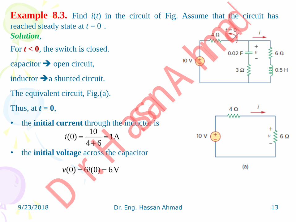
Example 8.3. Find i(t) in the circuit of Fig. Assume that the circuit has
reached steady state at t = 0–.
Solution,
For t < 0, the switch is closed.
capacitor open circuit,
inductor a shunted circuit.
The equivalent circuit, Fig.(a).
Thus, at t = 0,
• the initial current through the inductor is
• the initial voltage across the capacitor
9/23/2018 Dr. Eng. Hassan Ahmad 13
10(0) 1A
4 6i
(0) 6 (0) 6Vv i
Dr. H
assan A
hmad

For t > 0, the switch is opened.
The voltage source is disconnected, Fig.(b).
(source free series RLC circuit),
where the 3-Ω and 6-Ω resistors are in series
when the switch is opened:
The roots are calculated as follows:
9/23/2018 Dr. Eng. Hassan Ahmad 14
3 6 9R
0
2 2
1,2 0
9 1 19, 10
12 1 12( )2 2 50
9 81 10
9, 4.
0
9
3
4
9
.359
5
d
d
R
L L
j j
C
s
Dr. H
assan A
hmad
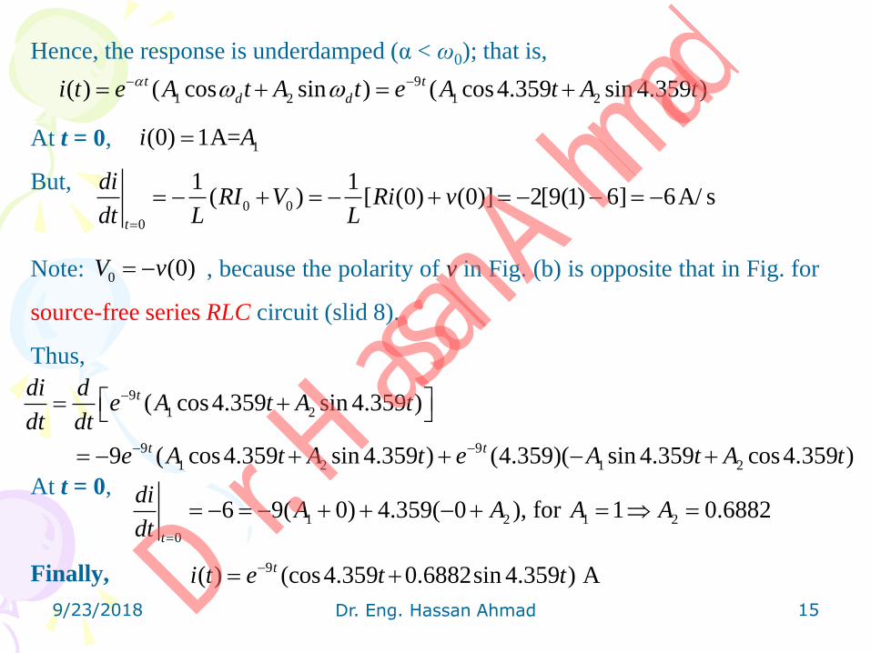
Hence, the response is underdamped (α < ω0); that is,
At t = 0,
But,
Note: , because the polarity of v in Fig. (b) is opposite that in Fig. for
source-free series RLC circuit (slid 8).
Thus,
At t = 0,
Finally,
9/23/2018 Dr. Eng. Hassan Ahmad 15
9
1 2 1 2( ) ( cos sin ) ( cos4.359 sin 4.359 )t t
d di t e A t A t e A t A t
1(0) 1A=i A
0 0
0
1 1( ) [ (0) (0)] 2[9(1) 6] 6A/ s
t
diRI V Ri v
dt L L
0 (0)V v
9
1 2
9 9
1 2 1 2
( cos4.359 sin 4.359 )
9 ( cos4.359 sin 4.359 ) (4.359)( sin 4.359 cos4.359 )
t
t t
di de A t A t
dt dt
e A t A t e A t A t
1 2 1 2
0
6 9( 0) 4.359( 0 ), for 1 0.6882t
diA A A A
dt
9( ) (cos4.359 0.6882sin 4.359 ) Ati t e t t Dr. H
assan A
hmad

8.4 Source-Free Parallel RLC Circuits
Parallel RLC circuits find many practical applications, notably in
communications networks and filter designs.
Consider the parallel RLC circuit shown in Fig.
• Assume initial inductor current I0 and initial capacitor voltage V0,
• Thus, applying KCL at the top node gives
• Taking the derivative with respect to t
and dividing by C results in
where s is first derivative, s2 is second derivative.
9/23/2018 Dr. Eng. Hassan Ahmad 16
0
0 0
1(0) ( ) , (0)i I v t dt v V
L
01( ) 0
v dvv d C
R L dt
2
2
2 1 10
1 10
d v dvv
dt RC dt LCs s
RC LC
Dr. H
assan A
hmad

The roots of characteristic equation are
or
There are three possible solutions,
1. Overdamped Case.
The response is
2. Critically Damped Case.
The response is
9/23/2018 Dr. Eng. Hassan Ahmad 17
1
2
2
,2
1 1 11
2
1
20 s
RC RCL Cs
Ls
RC C
2 2
1,2 0s 0
1 1,
2RC LC
1 2
2
2 2
1 2 1,
0
2 0( )
, i.e. 4
, s t s t
v t Ae A e s
L R C
2
2 2
0
1 1
, . . 4
(real, )( ) ( ) tv t A A t e s s
i e L R C
Dr. H
assan A
hmad

3. Underdamped Case.
The response is
• The constants A1 and A2 in each case can be determined from the initial
conditions. We need v(0) and dv(0)∕dt.
at the top node
9/23/2018 Dr. Eng. Hassan Ahmad 18
2 2
1 2 0 1,2( ) cos sin , ,t
d d d dv t A t A t e s j
0
0 0
1(0) ( ) , (0)i I v t dt v V
L
0
0 0
00
( )(0
1 (0)(
o)
r
) 0
V RI
Vv dv dvv d C I C
R L dt R dt
dv
dt RC
2
0 , i.e. 4L R C
Dr. H
assan A
hmad

Example 8.4. In the parallel circuit of Fig., find v(t) for t > 0, assuming
v(0) = 5 V, i(0) = 0, L = 1 H, and C = 10 mF. Consider these cases: R = 1.923 Ω,
R = 5 Ω, and R = 6.25 Ω.
Solution:
CASE 1: R = 1.923 Ω,
Since α > ω0 in this case, the response is overdamped. So,
the corresponding response is
We now apply the initial conditions to get A1 and A2 :
9/23/2018 Dr. Eng. Hassan Ahmad 19
3
03
1 126
2 2 1.923 10 10
1 110
1 10 10
RC
LC
2 2
1,2 0 1 2 2, 50s s s 2 50
1 2( ) t tv t Ae A e
1 2(0) 5 (1)v A A
0
3
0 (0) (0) (0) 5 0260
1.923 10
)0)
10
(( dv v RiV RIdv
dt RC dt RC
Dr. H
assan A
hmad

But
At t = 0,
From Eqs. (1) and (2), we obtain A1 = −0.2083 and A2 = 5.208.
Finally,
CASE 2: R = 5 Ω,
Since α > ω0 in this case, the response is damped. So,
To get A1 and A2 , we apply the initial conditions:
But,
At t = 0,
Finally,
9/23/2018 Dr. Eng. Hassan Ahmad 20
2 50 2 50
1 2 1 2( ) 2 50t t t tdvv t Ae A e Ae A e
dt
1 2260 2 50 (2)A A
2 50( ) 0.2083 5.208t tv t e e
03 3
1 1 1 110, 10
2 2 5 10 10 1 10 10RC LC
2 2 10
1,2 0 1 2 1 2 1 2 10, ( ) ( ) ( ) ( )t ts s s v t A A t e v t A A t e
1 3
(0) (0) (0) 5 0(0) , 100
5 10 105
dv v Riv
d RCA
t
10
1 2 2( 10 10 ) tdvA A t A e
dt
21 2 50100 10A A A
10( ) (5 50 ) Vtv t t e Dr. H
assan A
hmad

CASE 3: R = 6.25 Ω,
Since α < ω0 in this case, the response is underdamped. So,
To get A1 and A2 , we apply the initial conditions:
But,
At t = 0,
Finally,
9/23/2018 Dr. Eng. Hassan Ahmad 21
03 3
1 1 1 110, 10
2 2 5 10 10 1 10 10RC LC
2 2
1,2 0 1,2 8 6 6d ds s j j
31
(0) (0) (0) 5 0(0) , 80
6.25 10 15
0
dv v Ri
dAv
t RC
8
1 2
8
1 2 1 2
cos6 sin 6
( 8 cos6 8 sin 6 6 sin 6 6 cos6 )
t
t
dv dA t A t e
dt dt
A t A t A t A t e
1 2 2 6.6 780 8 6 6A A A
8( ) 5cos6 6.667sin 6 tv t t t e
8
1 2( ) cos6 sin 6 tv t A t A t e
Dr. H
assan A
hmad

Notice that by increasing the value of R, the degree of damping decreases and
the responses differ ( تتباين = تختلف ). Figure plots the three cases of Example 8.4.
9/23/2018 Dr. Eng. Hassan Ahmad 22 Dr. H
assan A
hmad
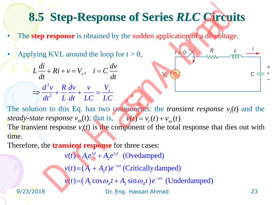
8.5 Step-Response of Series RLC Circuits
• The step response is obtained by the sudden application of a dc voltage.
• Applying KVL around the loop for t > 0,
The solution to this Eq. has two components: the transient response vt(t) and the
steady-state response vss(t); that is,
The transient response vt(t) is the component of the total response that dies out with
time.
Therefore, the transient response for three cases:
9/23/2018 Dr. Eng. Hassan Ahmad 23
2
2
,s
sVd v R dv v
d
di dvL Ri v V i C
d
t L dt LC L
t dt
C
( ) ( ) ( )t ssv t v t v t
1 2
1 2
1 2
1 2
( ) (Ovedamped)
( ) ( ) (Criticallydamped)
( ) cos sin (Underdamped)
s t s t
t
t
d d
v t Ae A e
v t A A t e
v t A t A t e
Dr. H
assan A
hmad
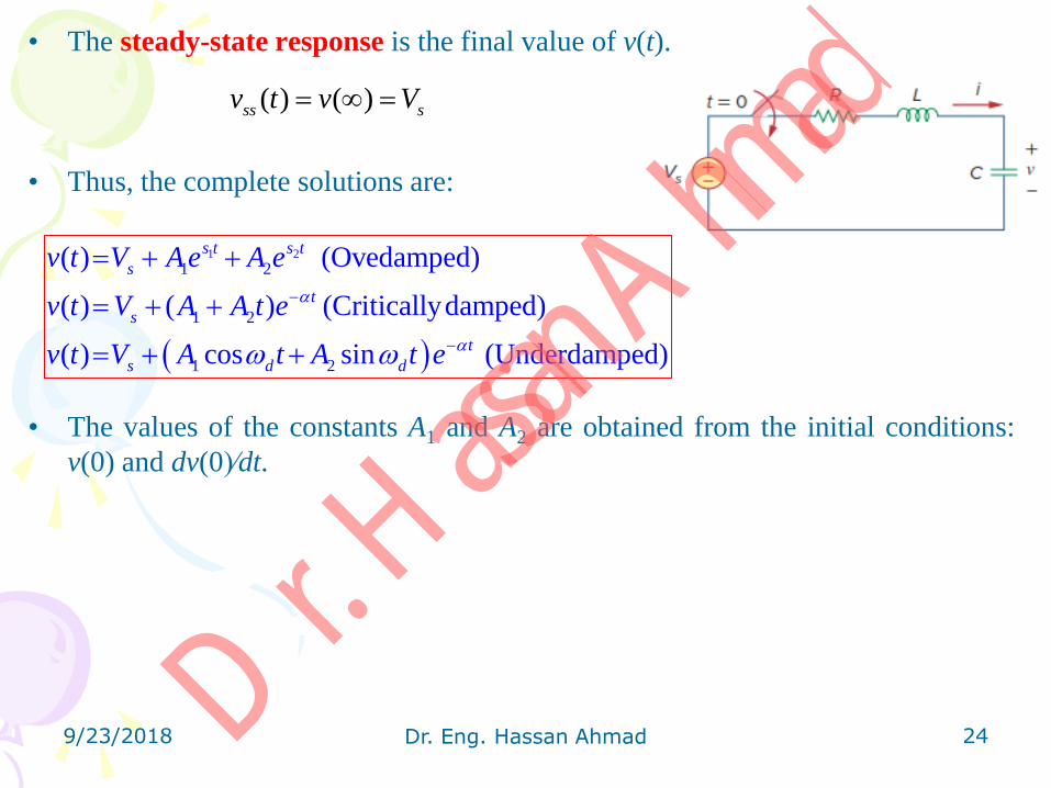
• The steady-state response is the final value of v(t).
• Thus, the complete solutions are:
• The values of the constants A1 and A2 are obtained from the initial conditions:
v(0) and dv(0)∕dt.
9/23/2018 Dr. Eng. Hassan Ahmad 24
1 2
1 2
1 2
1 2
( ) (Ovedamped)
( ) ( ) (Criticallydamped)
( ) cos sin (Underdamped)
s t s t
s
t
s
t
s d d
v t V Ae A e
v t V A A t e
v t V A t A t e
( ) ( )ss sv t v V
Dr. H
assan A
hmad
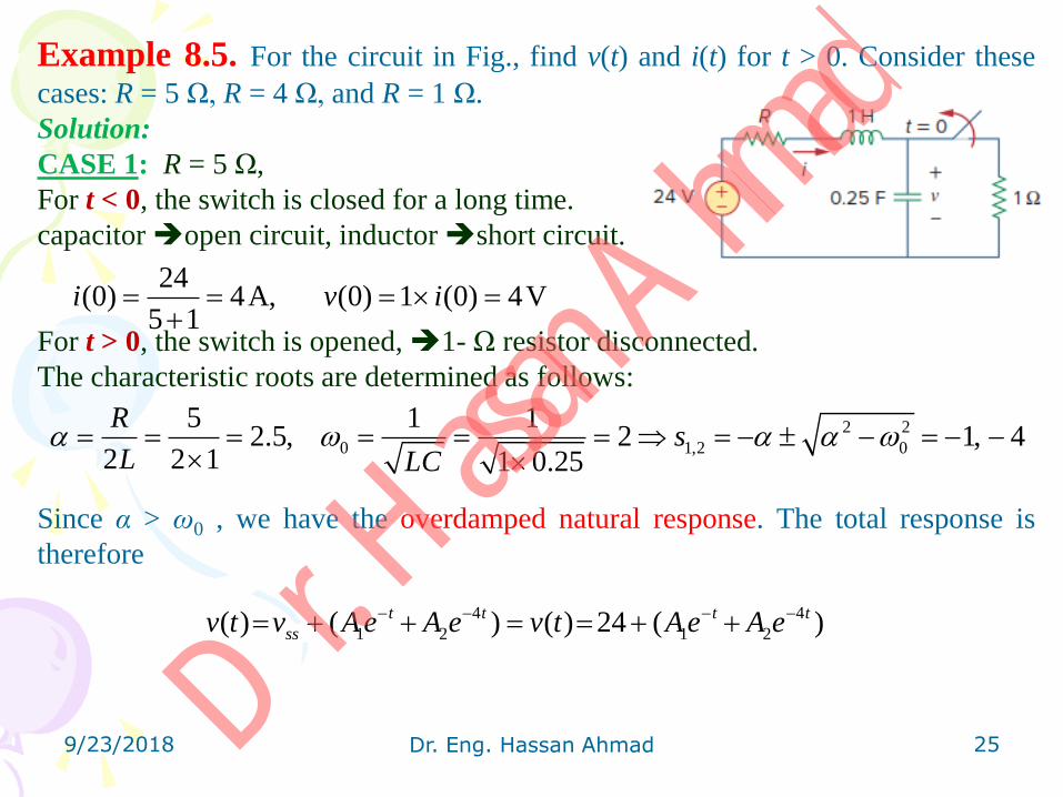
Example 8.5. For the circuit in Fig., find v(t) and i(t) for t > 0. Consider these
cases: R = 5 Ω, R = 4 Ω, and R = 1 Ω.
Solution:
CASE 1: R = 5 Ω,
For t < 0, the switch is closed for a long time.
capacitor open circuit, inductor short circuit.
For t > 0, the switch is opened, 1- Ω resistor disconnected.
The characteristic roots are determined as follows:
Since α > ω0 , we have the overdamped natural response. The total response is
therefore
9/23/2018 Dr. Eng. Hassan Ahmad 25
24(0) 4A, (0) 1 (0) 4V
5 1i v i
2 2
0 1,2 0
5 1 12.5, 2 1, 4
2 2 1 1 0.25
Rs
L LC
4 4
1 2 1 2( ) ( ) ( ) 24 ( )t t t t
ssv t v Ae A e v t Ae A e
Dr. H
assan A
hmad

To find A1 and A2 using the initial conditions:
But,
At t = 0,
From Eqs. (1) and (2):
Finally,
Since the inductor and capacitor are in series for t > 0, the inductor current is the
same as the capacitor current. Hence,
9/23/2018 Dr. Eng. Hassan Ahmad 26
1 2 1 2 20 (1(0) 4 4 )2v A A A A
(0) (0) 4 4(0) 4 16
0.25
dv dvi C
dt dt C
4 4
1 2 1 224 ( ) 4t t t tdv dAe A e Ae A e
dt dt
1 21 2)
4 ( )(
60d
Av
dtA
1 264 3, 4 3A A
44( ) 24 ( 16 ) V
3
t tv t e e
44( ) ( ) (4 ) A
3
t tdvi t C i t e e
dt
Dr. H
assan A
hmad
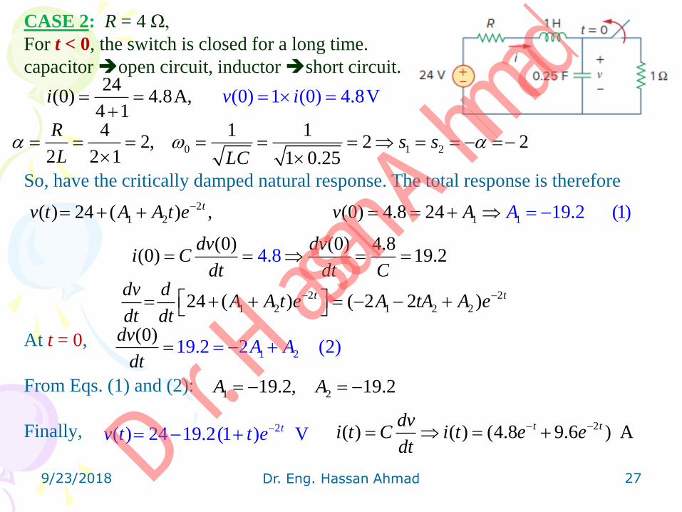
CASE 2: R = 4 Ω,
For t < 0, the switch is closed for a long time.
capacitor open circuit, inductor short circuit.
So, have the critically damped natural response. The total response is therefore
At t = 0,
From Eqs. (1) and (2):
Finally,
9/23/2018 Dr. Eng. Hassan Ahmad 27
24(0) 4.8A (0) 1 (0) 4,
1V
4.8v ii
0 1 2
4 1 12, 2 2
2 2 1 1 0.25
Rs s
L LC
2
1 12 1( ) 24 ( ) , (0) 4.8 2 19.24 (1)tv t A A t e v A A
4.8(0) (0) 4.8
(0) 19.2dv dv
i Cdt dt C
2 2
1 2 1 2 224 ( ) ( 2 2 )t tdv dA A t e A tA A e
dt dt
1 219.2 2(
)0)
(2A Adv
dt
1 219.2, 19.2A A
2( ) 24 19.2(1 ) Vtv t t e 2( ) ( ) (4.8 9.6 ) At tdv
i t C i t e edt
Dr. H
assan A
hmad
CASE 3: R = 1 Ω,
For t < 0, the switch is closed for a long time.
capacitor open circuit, inductor short circuit.
Since α < ω0 in this case, the response is underdamped. So,
The total response is:
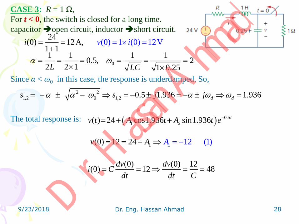
9/23/2018 Dr. Eng. Hassan Ahmad 28
(0) 1 (0) 124
(0) 12A, 2V1 1
v ii
0
1 1 1 10.5, 2
2 2 1 1 0.25L LC
2 2
1,2 0 1,2 0.5 1.936 1.936d ds s j j
0.5
1 2( ) 24 cos1.936 sin1.936 tv t A t A t e
11 12 (1)(0) 12 24v A A
(0) (0) 12(0) 12 48
dv dvi C
dt dt C
Dr. H
assan A
hmad

But
At t = 0,
From Eqs. (1) and (2):
Finally,
The inductor current is:
9/23/2018 Dr. Eng. Hassan Ahmad 29
0.5
1 2
0.5
1 2
0.5
1 2
24 cos1.936 sin1.936
( 1.936 sin1.936 1.936 cos1.936 )
0.5 ( cos1.936 sin1.936 )
t
t
t
dv dA t A t e
dt dt
A t A t e
e A t A t
2 148 ( 0 1.93(
6 ) 0.5( 0) (0
2))
Ad
dtA
v
1 212, 21.694A A
0.5( ) 24 21.694sin1.936 12cos1.936 Vtv t t t e
0.5( ) ( ) 3.1sin1.936 12cos1.936 Atdvi t C i t t t e
dt
Dr. H
assan A
hmad
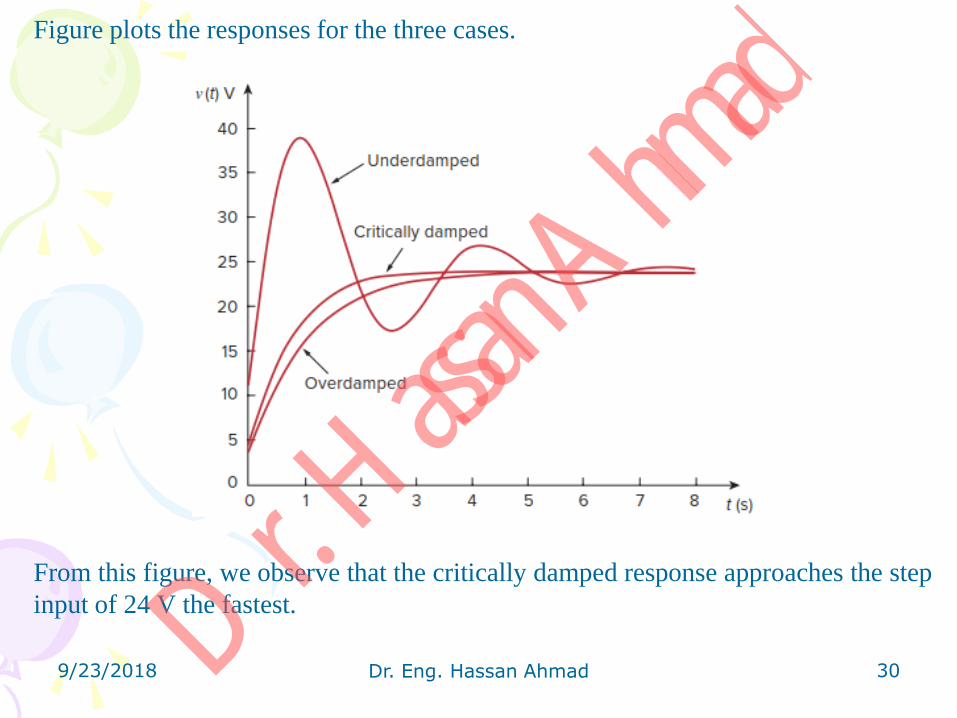
Figure plots the responses for the three cases.
From this figure, we observe that the critically damped response approaches the step
input of 24 V the fastest.
9/23/2018 Dr. Eng. Hassan Ahmad 30 Dr. H
assan A
hmad

8.6 Step-Response of Parallel RLC Circuits
The step response is obtained by the sudden application of a dc current.
• Applying KCL at the top node for t > 0,
The complete solution consists of the transient response it(t) and the steady-state
response iss(t); that is,
The final value of the current through the inductor is the same as the source
current Is. Thus,
The constants A1 and A2 in each case can be determined from the initial
conditions for i and di∕dt.
9/23/2018 Dr. Eng. Hassan Ahmad 31
s
v dvi C I
R dt
2
2
1with sIdi d i di i
v Ldt dt RC dt LC LC
( ) ( ) ( )t ssi t i t i t
1 2
1 2
1 2
1 2
( ) (Ovedamped)
( ) ( ) (Criticallydamped)
( ) cos sin (Underdamped)
s t s t
s
t
s
t
s d d
i t I Ae A e
i t I A A t e
i t I A t A t e
Dr. H
assan A
hmad

Example 8.6. In the circuit of Fig., find i(t) and iR(t) for t > 0.
Solution:
For t < 0, the switch is open, and the circuit is partitioned into two independent
subcircuits, Fig.(a).
• The 4-A current flows through the inductor, so that
• t < 0 30u(− t) = 30; t > 0 30u(− t) = 0, the voltage source is operative
for t < 0.
9/23/2018 Dr. Eng. Hassan Ahmad 32
(0) 4Ai
Dr. H
assan A
hmad
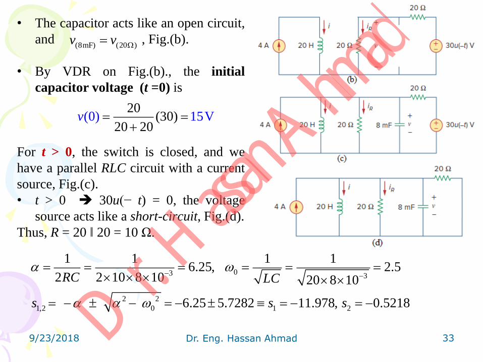
• The capacitor acts like an open circuit,
and , Fig.(b).
• By VDR on Fig.(b)., the initial
capacitor voltage (t =0) is
For t > 0, the switch is closed, and we
have a parallel RLC circuit with a current
source, Fig.(c).
• t > 0 30u(− t) = 0, the voltage
source acts like a short-circuit, Fig.(d).
Thus, R = 20 ‖ 20 = 10 Ω.
9/23/2018 Dr. Eng. Hassan Ahmad 33
(8mF) (20 )v v
20(30)
20 2(0) 15V
0v
03 3
2 2
1,2 0 1 2
1 1 1 16.25, 2.5
2 2 10 8 10 20 8 10
6.25 5.7282 11.978, 0.5218
RC LC
s s s
Dr. H
assan A
hmad

Since α > ω0 we have the overdamped case. Hence,
At t = 0,
But
so that at t = 0,
But
Thus,
From Eqs.(1) and (2):
The complete solution is as
9/23/2018 Dr. Eng. Hassan Ahmad 34
1 2 11.978 0.5218
1 2 1 2( ) 4s t s t t t
si t I Ae A e Ae A e
1 2 2 1(0) 4 (1)4i A A A A
11.978 0.5218 11.978 0.5218
1 2 1 24 11.978 0.5218t t t tdi dAe A e Ae A e
dt dt
1 2
(0)11.978 0.5218
diA A
dt
( ) (0) (0)0.
15 15( ) (0)
275
015
di t di div t L v L
dt dt dt L
1 211.978 0.5218 0.75 (2)A A
2 10.0655, 0.0655A A
0.5218 11.978( ) 4 0.0655( ) At ti t e e
11.978 0.5218( ) 1( ) ( ) 0.785 0.0342 A
20 20
t t
R
v t dii t L i t e e
dt
Dr. H
assan A
hmad

35
9/23/2018 Dr. eng. Hassan Ahmad Dr. H
assan A
hmad