electric chain hoist stageket - elektrokettenzüge · electric chain hoist stageket ... (bgv d8)...
TRANSCRIPT

Issue March 2016
ELECTRIC CHAIN HOIST STAGEKET O p e r a t i n g I n s t r u c t i o n s - Original -
Please do not use the electric chain hoist before all operators have carefully read and understood this manual and signed the form on the rear cover.


3
Contents
1 Safety instructions ....................................................................................................................................... 5
1.1 Regulations .................................................................................................................................................. 5
1.2 Advice for the use of electric chain hoists .................................................................................................... 6
1.2.1 Design according to DGUV V54 (BGV D8) .................................................................................................. 6
1.2.2 Additional requirements when designed according to DGUV V17 (BGV C1) .............................................. 7
1.3 Prohibitions of use ....................................................................................................................................... 7
1.4 Directions for use ......................................................................................................................................... 7
1.5 Visible damages .......................................................................................................................................... 8
1.6 Special features of electric chain hoists according to DGUV V17 (BGV C1) ............................................... 8
1.6.1 Prohibitions of use ....................................................................................................................................... 8
1.6.2 Moving of loads............................................................................................................................................ 8
1.6.3 Persons underneath suspended loads ........................................................................................................ 8
1.6.4 Types of loads ............................................................................................................................................. 8
1.6.5 Attaching lights or other equipment to the electric chain hoists ................................................................... 9
1.7 Spare parts .................................................................................................................................................. 9
2 Technical overview ...................................................................................................................................... 9
2.1 Assembly ..................................................................................................................................................... 9
2.1.1 Standard version and version MB in upright use according to DGUV V54 (BGV D8) .................................. 9
2.1.2 Version MB in inverted use according to DGUV V54 (BGV D8) ................................................................ 10
2.1.3 Version SB in upright use according to DGUV V17 (BGV C1) ................................................................... 11
2.1.4 Further completion possibilities ................................................................................................................. 11
2.2 Explanation of type designation ................................................................................................................. 11
2.3 Sectional view ............................................................................................................................................ 12
2.4 Illustration of the load chain configuration .................................................................................................. 13
3 Assembly ................................................................................................................................................... 13
3.1 Mechanical assembly ................................................................................................................................ 13
3.1.1 Hook tackle ................................................................................................................................................ 13
3.1.2 Hook block ................................................................................................................................................. 14
3.1.3 Stationary electric chain hoist .................................................................................................................... 15
3.1.3.1 Hoist suspension with suspension eye ...................................................................................................... 15
3.1.3.2 Hoist suspension with single hole suspension eye .................................................................................... 16
3.1.3.3 Hoist suspension with hook suspension .................................................................................................... 17
3.1.4 Gear ventilation.......................................................................................................................................... 18
3.1.5 Chain box .................................................................................................................................................. 18
3.1.5.1 Mounting the chain box .............................................................................................................................. 18
3.1.5.2 Oversize chain box .................................................................................................................................... 19
3.1.6 Assembling the load chain in single fall version ......................................................................................... 20
3.1.7 Assembling the load chain in double fall version ....................................................................................... 21
3.1.8 Replacing the load chain, the chain guide and the hold down ................................................................... 22
3.1.9 Lift limiter ................................................................................................................................................... 22
3.2 Electric connections ................................................................................................................................... 22
3.2.1 Mains power .............................................................................................................................................. 22
3.2.2 Operating voltages..................................................................................................................................... 23
3.2.3 Direct control ............................................................................................................................................. 24
3.2.4 Low voltage control .................................................................................................................................... 24
3.2.5 Electrical limit switches for lift limiting ........................................................................................................ 25
3.3 Configuration of electric chain hoists according to DGUV V17 (BGV C1) .................................................. 25
3.4 Limit switches in upright use ...................................................................................................................... 26
3.5 Limit switches in inverted use .................................................................................................................... 26
3.6 Operation and emergency limit switches ................................................................................................... 26
3.6.1 Gear limit switches ..................................................................................................................................... 26
3.6.2 External emergency limit switches ............................................................................................................. 27
3.7 Incremental encoder .................................................................................................................................. 28
3.8 Mechanical underload protection ............................................................................................................... 29
3.9 Electronic overload and underload protection ............................................................................................ 30
3.10 Control pendant ......................................................................................................................................... 32
4 Electric chain hoist with trolley ................................................................................................................... 33
4.1 Types of trolleys......................................................................................................................................... 33
4.2 Permissible curve radius ............................................................................................................................ 33
4.3 Horizontal movement of electric chain hoists ............................................................................................. 34
4.4 Attachment of lightening devices to electric chain hoists ........................................................................... 34

4
4.5 Mechanical assembly ................................................................................................................................ 34
4.5.1 Assembly position of the trolley on the electric chain hoist ........................................................................ 34
4.5.2 Assembly of the trolley with two connecting bolts...................................................................................... 35
4.5.3 Assembly of the trolley with tandem trolley ............................................................................................... 35
4.5.4 Assembly of the trolley with one connecting bolts ..................................................................................... 36
4.6 Electric trolleys with counterweight ............................................................................................................ 36
4.7 Electric connection of electric trolleys ........................................................................................................ 36
5 Initial operation .......................................................................................................................................... 36
5.1 Initial operation according to DGUV V54 (BGV D8) .................................................................................. 36
5.2 Initial operation according to DGUV V17 (BGV C1) .................................................................................. 36
6 Tests ......................................................................................................................................................... 37
6.1 Test when used according to DGUV V54 (BGV D8) §23 - Winches, lifting and pulling equipment ........... 37
6.2 Test when used according to DGUV V52 (BGV D6) §25 - Cranes ............................................................ 37
6.3 Regular tests ............................................................................................................................................. 37
6.4 Additional tests according to DGUV V17 (BGV C1) .................................................................................. 37
7 Maintenance .............................................................................................................................................. 38
7.1 Maintenance and checks ........................................................................................................................... 38
7.2 Single brake .............................................................................................................................................. 39
7.2.1 Description of the single brake .................................................................................................................. 39
7.2.2 Replacement of the brake ......................................................................................................................... 39
7.3 Double brake SK 02../... und SK03../... ...................................................................................................... 40
7.3.1 Description of the double brake ................................................................................................................. 40
7.3.2 Replacement of the brake ......................................................................................................................... 40
7.4 Double brake SK 05../... und SK07../... ...................................................................................................... 41
7.4.1 Description of the double brake ................................................................................................................. 41
7.4.2 Replacement of the brake ......................................................................................................................... 42
7.5 Electric control of the brake ....................................................................................................................... 43
7.6 Troubleshooting on the brake .................................................................................................................... 43
7.7 Functional check of the brake.................................................................................................................... 43
7.7.1 Operation- and emergency brake (double brake) ...................................................................................... 44
7.8 Safety sliding clutch ................................................................................................................................... 45
7.8.1 Construction of safety sliding clutch .......................................................................................................... 45
7.8.2 Adjustment of friction torque at the safety sliding clutch ............................................................................ 46
7.8.3 Checking the release limit of the sliding clutch during regular inspections ................................................ 46
7.9 Assembly and disassembly of the brake-clutch assembly group............................................................... 47
7.10 Load chain ................................................................................................................................................. 47
7.10.1 Lubrication of the load chain before initial operation and during operation ................................................ 47
7.10.2 Testing of wear and replacement of the load chain ................................................................................... 48
7.11 Measuring wear and replacing load hook .................................................................................................. 48
7.12 Maintenance work on the trolleys .............................................................................................................. 49
7.12.1 Construction of the brake of the electric trolley.......................................................................................... 49
8 Duty rate of an electric chain hoist ............................................................................................................ 50
8.1 Short time duty .......................................................................................................................................... 50
8.2 Intermittent duty ......................................................................................................................................... 51
8.3 Example .................................................................................................................................................... 51
9 Duty rate of the electric trolleys ................................................................................................................. 51
10 Strainer clamp for the control cable ........................................................................................................... 52
11 Lubricants / Auxiliary materials .................................................................................................................. 52
11.1 Gear .......................................................................................................................................................... 52
11.2 Chain ......................................................................................................................................................... 53
11.3 Hook block and hook tackle....................................................................................................................... 54
11.4 Trolley ....................................................................................................................................................... 54
12 Measures to be taken at the end of the S.W.P. ......................................................................................... 54
13 Example of Declaration of Conformity ....................................................................................................... 55
14 Example of Declaration of Incorporation ................................................................................................... 56

5
1 Safety instructions 1.1 Regulations The following regulations and all recommendations of this manual serve as basis for assembly, installation, certification and maintenance of electric chain hoists, within Germany and within the area of the European community. For countries other than mentioned, local legislation and directives may apply in addition to the regulations as stated in this manual (German/European). Please pay particular attention to the rules for the prevention of accidents and the statutory regulations.
European Regulations
2006/42/EC EC-Machine directive
2004/108/EC EC-Directive relating to electromagnetic compatibility
2006/95/EC EC-electrical equipment designed for use within certain voltage limits
BGV accident prevention regulations
DGUV Vorschrift 3 (BGV A1) Principles of prevention
DGUV Vorschrift 3 (BGV A3) Electrical facilities and equipment
DGUV Vorschrift 52 (BGV D6) Accident prevention regulation for use in crane systems
DGUV Vorschrift 54 (BGV D8) Accident prevention regulation for electric winches, lifting and pulling equipment
DGUV Regel 100-500 (BGR 500) Hoisting accessories
DGUV Grundsatz 309-001 (BGG 905) Principles for crane inspections
Harmonized regulations
DIN EN ISO 12100:2010 Safety of machinery; Basic terminology, methodology
DIN EN 14492-2:2006+A1:2009 Cranes - Power driven winches and hoists
DIN EN 818-7:2002+A1:2008 Short link chain for lifting purposes; Fine tolerance hoist chain, Grade T
DIN EN ISO 13849-1:2008 Safety of machinery - Safety-related parts of control systems; General principles for design
DIN EN 60034-1:2010 Rotating electrical machines; Rating and performance
DIN EN 60034-5:2001+A1:2007 Rotating electrical machines; Degrees of protection provided by the integral design of rotating electrical machines
DIN EN 60204-1:2006 Electrical equipment of machines, General requirements
DIN EN 60204-32:2008 Electrical equipment of machines; Requirements for hoisting machines
DIN EN 60529:1991+A1:2000 Degrees of protection provided by enclosures (IP-Code)
DIN EN 60947-1:2007+A1:2011 Low-voltage switchgear and control gear
DIN EN 61000-6-2:2005 Electromagnetic compatibility, Immunity for industrial environments
DIN EN 61000-6-3:2007+A1:2011 Electromagnetic compatibility, Emission standard for residential, commercial and light-industrial environments
DIN EN 61000-6-4:2007+A1:2011 Electromagnetic compatibility, Emission standard for industrial environments
DIN EN 82079-1:2013 Preparation of instructions for use - Structuring, content and presentation
Regulations and technical specifications
FEM 9.511:1986 Rules for the design of series lifting equipment; Classification of mechanisms
FEM 9.683:1995 Series lifting equipment; Selection of hoisting and travelling motors
FEM 9.751:1998 Series lifting equipment; Power driven series hoist mechanisms; Safety
FEM 9.755:1993 Serial hoist units; Measures for achieving safe working periods
The producers guarantee depends on consideration of these regulations and of operating instructions. Other national regulations are valid for countries outside of the European community.

6
1.2 Advice for the use of electric chain hoists 1.2.1 Design according to DGUV V54 (BGV D8) Electric chain hoists are designed to lift and to lower loads vertically and to travel horizontally with those lifted loads (with trolleys). Any other use is not considered to be proper. Manufacturer does not take responsibility for any improper use and the risk is on the operator’s responsibility. The use of the electric chain hoist in an aggressiv e environment is not allowed without permission of the manufacturer. To this effect, it may be necessary to make certain components from different materials. The electric chain hoist can only be operated by personnel, who have complete knowledge of this manual, and have unhindered access to it. Do not operate the electric chain hoist until all operators have thorough knowledge of this manual, and acknowledge that by signing the allocated field on the rear cover of this brochure. If properly used, the modern design of the electric chain hoists guarantees safety and economic operation. The safety friction clutch is located outside of the load path, which enables stopping the load without putting strain on the clutch. The force of the brake acts via a form-locked join on the gear and therefore it will be directly transmitted on the load.
Before first use make sure, that all electrical wires are connected in accordance with the instructions, that all wires are without damages and that the whole equipment could be switched off by a main switch. It is the responsibility of the operator to make sure that all suspension points of the hoist are designed to safely withstand the dynamic forces caused by the lifting equipment. The chain hoist can only be used when it is suspended according to specification and the outgoing chain can leave the hoist safely, by its own weight, in the relevant direction. Therefore the container for the dead end of the chain outside the hoist must be big enough to allow the chain to come out. If not, the chain can be trapped inside the hoist and can break the casing of the hoist.
Maintenance work on electric chain hoists has to be carried out by trained and authorised people only. The main switch has to be switched off and the working area is to be secured beforehand.
Authorised people have to have a theoretical training as well as experience in the field of winches, lifting and pulling equipment or cranes. They have to possess an excellent knowledge of the relevant work safety regulations, directives, and general accepted rules of lifting techniques, which enables them to decide whether the lifting equipment is in a safe working condition or not. Any maintenance work and inspections are to be entered into the crane inspection book (e.g. brake or clutch adjustments). This manual will tell you how to operate the hoist and how to handle its suspension or its loads safely. The following safety advices have to be observed. The safety instructions may not be complete for each mode of use. If there are any questions or problems contact the manufacturer or our local representative. This Operating Instructions should always be in a complete and fully readable condition. No responsibility is taken for damages and operating troubles due to the following reasons: • improper use • unauthorised modification of the drive system • unworkmanlike work done on the system and with the system • operating errors • Failure to use the product as instructed in the manual

7
1.2.2 Additional requirements when designed accordi ng to DGUV V17 (BGV C1) The electric chain hoists in the design ‚SB‘ (with 2 brakes and half load capacity) are subject to requirements of DGUV V17 (BGV C1). The operators have to be well trained in order to make them aware about the special requirements, resulting from stage and studio use of chain hoists according to DGUV V17 (BGV C1). The operation instructions have to be read carefully by the operators and they shall sign a form stating that they have got the information.
1.3 Prohibitions of use • Do not use the chain hoist to carry people. It is s trictly prohibited. • Do not use the chain hoist in inching mode (fast sw itching on / off of functions). • Do not permanent run against the rubber buffers of the lowest and highest hook position
(ultimate safety limit for emergency only). • Do not use the chain hoist with people being undern eath the load.
This does not apply to electric chain hoists in acc ordance with DGUV V17 (BGV C1).
• Do not move loads heavier than the nominal load. • Do not pull loads diagonally or drag loads. • Do not tear off loads. • Do not remove the cover of vessels, which are under vacuum. • Do not move a trolley by pulling the control pendant or the control cable, even if these are relieved of
strain. • Do not use the lifting chain to sling the loads. • Do not use the chain hoist with a lifting chain, which is longer than stated on the chain box.
• Do not start the initial operation before an expert or a trained specialist has inspected the equipment. • Do not carry out repairs without special knowledge. • Do not use the chain hoist with higher duty rate as marked on the specification plate. • Do not use the chain hoist without having done the regular inspection. 1.4 Directions for use • The load may only be moved if it is slung securely and no person is standing under the load or near
enough to be at risk DGUV V54 (BGV D8). • The load must be placed vertically under the electric hoist before lifting. • The motion directions are indicated with symbols on the control buttons. • Do not turn the chain over edges. • Do not lower the double fall hook until the chain gets slack. • Consult the manufacturer, if the hoist is to be used in an aggressive environment • Consult the manufacturer, when transporting red-hot melts or similar dangerous materials. • Repair work can be done by specialists only if mains supply is switched off and secured and no load
is suspended on the hook. • After an emergency stop button actuation, the cause of actuation has to be found and all possible
failures removed by expert personnel. Reset emergency pushbutton only after this procedure. • Lifting the load from the ground has to be done with the lowest possible speed. Before doing this
slack sling chains or ropes have to be tightened carefully. • When operating a chain hoist at a height that is reachable by hand, do not touch the hoist at the
chain entry. Proper safety measures have to be established to avoid the risk of squeeze.

8
1.5 Visible damages If any damages or breakdowns are detected during the operation or during hoist tests these hoists must not be operated until they have been repaired or a trained specialist has checked and approved them.
In case of broken load chain, the owner/operator shall not put the chain hoist into operation until the hoist has been checked, repaired and approved by an authorized specialist.
1.6 Special features of electric chain hoists accord ing to DGUV V17 (BGV C1) 1.6.1 Prohibitions of use • Do not stay underneath the load if this is not necessary (§19, DGUV V17 (BGV C1)). • Do not endanger persons (§§19, 26, DGUV V17 (BGV C1)). • Do not start initial operation before an authorized expert or a trained specialist has inspected and
approved the equipment (§§33, 34, DGUV V17 (BGV C1)). • Do not use the ultimate limit switch as an operation limit switch (§26 (6), DGUV V17 (BGV C1)).
1.6.2 Moving of loads Attention should be paid to the following: • The load has to be moved only if it is safely attached to the load hook. • Moving loads must not endanger persons. • There has to be a sufficient distance between moving and static parts.
• There has to be a visibility of the load by the operator at any time or any movement has to be done with a second person who has visibility of the load and the operator.
• Device to prevent an unauthorised operation of the hoist has to be provided by the owner / operator.
1.6.3 Persons underneath suspended loads There must not be any persons underneath a suspended load if it or parts of it could be lowered to less than 2000 mm above the floor where these persons are staying except this is required by the scenery of an event.
1.6.4 Types of loads It is permitted to attach one lighting device only to an electric chain hoist by a telescope hoist or pantographs. The safe working load (SWL) of the electric chain hoist should be adhered to. Several lighting devices are count as one device, if attached on the electric chain hoist at their centre of gravity. It is most important, that the same safety as for a single device should be reached. It is permitted to suspend more than one lighting device to a batten hoist. The safe working load (SWL) of the type plate of the electric chain hoist and the maximum single load on the batten hoist should not be exceeded. Follow the above advice also if other items are attached to the load hook in special cases.

9
1.6.5 Attaching lights or other equipment to the el ectric chain hoists Loads have to be attached from special scaffolds, approved working platforms or similar safe positions only.
1.7 Spare parts Only original fixing components, spare parts and accessories, listed in manufacturer’s spare parts catalogue are acceptable for use. The producers guarantee is given for those spare parts only. The producer cannot be held responsible for any damages due to the use of non-original parts and accessories. 2 Technical overview 2.1 Assembly The simple building block system makes it easy to convert an electric chain hoists to different versions. This allows the choice of single or double fall versions, stationary or mobile with push or electric trolleys, and the installation of greater hoisting and operating heights. 2.1.1 Standard version and version MB in upright use according to DGUV V54 (BGV D8) Shackle Single hole suspension eye (MB) Hook suspension Single hole suspension eye (standard) Suspension eye (standard) Hoisting gear Control pendant with emergency stop Hook block Hook tackle Lift limiter
Push- or electric trolley Frame for strain relief of chain box Oversize chain box with strainer strap Chain box
Figure 1: Assembly options of electric chain hoists in normal use

10
2.1.2 Version MB in inverted use according to DGUV V54 (BGV D8) Lift limiter Chain box Excess chain (to secure feeding into the chain box)
Hook tackle Chain guide plate Hoisting gear Single hole suspension eye (MB) Control pendant with emergency stop
Figure 2: Assembly options of electric chain hoists in inverted use

11
2.1.3 Version SB in upright use according to DGUV V17 ( BGV C1) Shackle Single hole suspension eye (MB) Hook suspension Single hole suspension eye (standard) Suspension eye (standard) Hoisting gear Control pendant with emergency stop Hook block Hook tackle Lift limiter
Push- or electric trolley Frame for strain relief of chain box Oversize chain box with strainer strap Chain box
Figure 3: Assembly options of electric chain hoists SB in normal use 2.1.4 Further completion possibilities Further completion possibilities will be provided on request. 2.2 Explanation of type designation Version STAGEKET SK 031/52 Type 500 / 2 – 4 / 1 Slow lifting speed [m/min] Main lifting speed [m/min] Number of falls Safe working load (SWL) [kg] According to the Machine directive 2006/42/EC you will find all technical data in the technical documentation attached to each hoist.
12
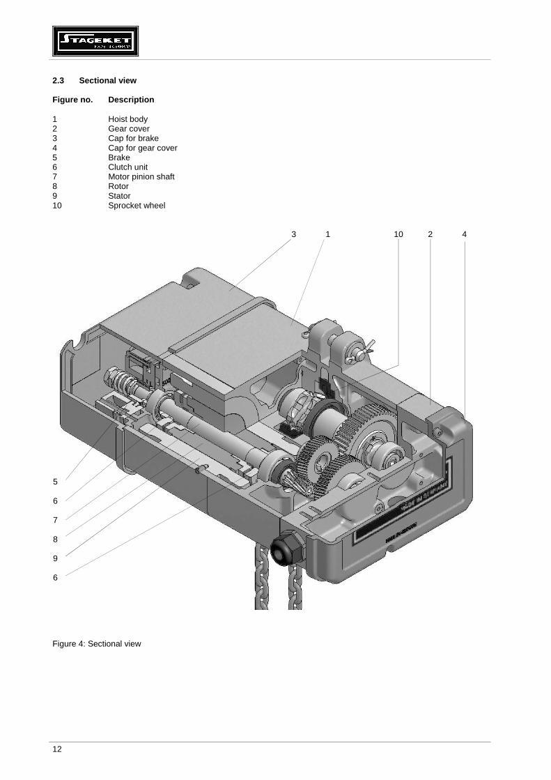
2.3 Sectional view Figure no. Description 1 Hoist body 2 Gear cover 3 Cap for brake 4 Cap for gear cover 5 Brake 6 Clutch unit 7 Motor pinion shaft 8 Rotor 9 Stator 10 Sprocket wheel 3 1 10 2 4
Figure 4: Sectional view
5 6 7 8 9 6

13
2.4 Illustration of the load chain configuration Attention!
Use original chain of the manufacturer only! These original chains meet the high stress and service life standards required.
Single fall version
Double fall version
Sprocket wheel Hold down Chain guide Chain box Lift limiter (limit stop) Hook tackle Chain fork Hook block
Figure 5: Configuration of load chain 3 Assembly Assembly work should only be carried out by trained specialist in accordance with DGUV V54 (BGV D8) § 24. 3.1 Mechanical assembly 3.1.1 Hook tackle The hook tackle is used to attach loads for hoists in single fall version.
Rubber buffer with vulcanized metal washer Threaded bolt Plastic cover with capacity label and chain size Casing with mark 4 or 5 Pressure disk Load hook complete (incl. axial pressure bearing)
Rubber buffer 2 hexagon head screws with self-locking nuts Casing Pressure disk Load hook complete (incl. axial pressure bearing)
Hook tackle for chains 4×12; 5×15 and 5.2×15
Hook tackle for chains 7×22 and 7.2×21
Figure 6: Details of the hook tackle

14
During maintenance work the condition of the load hook (wear and centre punch spacing), the rubber buffer, the pressure bearing, the safety latch and the pin, which secures the hook nut, have to be checked. If required, the axial bearing has to be cleaned and greased. The plastic cover of the hook tackles of chains 4×12 mm, 5×15 mm and 5.2×15 mm has to be checked additionally and changed if worn. For the assembly of the hook tackles please tighten the connection screws with the following torque: Max. S.W.L. [kg] Dimension of screws Quantity Tightening torque [Nm] hook tackle for chain 4×12 mm 250 - - -
hook tackle for chain 5×15 mm 500 - - -
hook tackle for chain 5.2×15 mm 500 - - -
hook tackle for chain 7×22 mm 1000 M10×40 DIN 912 2 35
hook tackle for chain 7.2×21 mm 1250 M10×40 DIN 912 2 35
Table 1: Tightening torques of screw connections 3.1.2 Hook block The hook block is used to attach the load in double fall version. Casing Radial ball bearing Load hook complete (incl. pressure bearing and hook nut)
Rubber buffer Sprocket wheel Screws complete with self-locking nuts and tooth washers
Figure 7: Details of the hook block During maintenance work the condition of the load hook (wear and centre punch spacing), the rubber buffer, the pressure bearing, the safety latch and the pin, which secures the hook nut, have to be checked. During assembly of the hook blocks the connection screws should be tightened with the following torque: Max. S.W.L. [kg] Dimension of screws Quantity
bottom/top Tightening torque [Nm] bottom/top
Hook block of chain 4×12 mm 500 M6×40 DIN 912 2/1 10/6
Hook block of chain 5×15 mm 1000 M6×40 DIN 912 2/1 10/6
Hook block of chain 5.2×15 mm 1000 M6×40 DIN 912 2/1 10/6
Hook block of chain 7×22 mm 2000 M8×50 DIN 912 2/1 20/10
Hook block of chain 7.2×21 mm 2500 M8×50 DIN 912 2/1 20/10
Table 2: Tightening torques of screw connections

15
3.1.3 Stationary electric chain hoist 3.1.3.1 Hoist suspension with suspension eye Caution!
It is not allowed to use any other non-original par ts, fixing bolts or screws to connect the electric chain hoist to the suspension. The hole for the tandem trolley on the suspension eye must be on the chain box side.
Assembly:
The suspension eye section must be inserted into the specially provided suspension holes on the electric chain hoist and pinned into place with the two bolts. Use washers with the lock bolts and secure position with split pins.
Suspension eye Hole for tandem trolley Bolts Chain box side
Figure 8: Suspension with suspension eye

16
3.1.3.2 Hoist suspension with single hole suspensio n eye Caution!
It is not allowed to use any other non-original par ts, fixing bolts or screws to connect the electric chain hoist to the suspension. The label of hook tackle used for the single fall version and the label of hook block used for the double fall version should be in the respective version on chain box side.
Assembly : Fix the provided single hole suspension eye to the special suspension holes of the electric chain hoist with suspension bolts. Use washers and secure with split pins. By rotating the suspension eye by 180° the single fall version or double fall version will be realized. This applies to the single hole suspension in standard version as well as in MB-version.
Single fall version
Double fall version
Single hole suspension eye short side Label of hook tackle
Chain box Hook tackle
Single hole suspension eye long side Label of hook block
Chain box Hook block
Figure 9: Suspension with single hole suspension eye

17
3.1.3.3 Hoist suspension with hook suspension Caution!
It is not allowed to use any other non-original par ts, fixing bolts or screws to connect the electric chain hoist to the suspension. The label of hook tackle used for the single fall version and the label of hook block used for the double fall version should be in the respective version on chain box side.
Assembly : Fix the provided hook suspension eye to the special suspension holes of the electric chain hoist with suspension bolts. Use washers and secure with split pins. By rotating the hook suspension by 180° the single fall version or double fall version will be realized.
Single fall version
Double fall version
Hook suspension short side Label of hook tackle
Chain box Hook tackle
Hook suspension long side Label of hook block
Chain box Hook block
Figure 10: Suspension with hook suspension

18
3.1.4 Gear ventilation After the completion of hoist installation, the serrated washer has to be placed under the oil filler plug (top side of casing) to avoid oil leakage due to high pressure inside the gearbox. You will find this washer fastened with a piece of self-adhesive tape next to the oil filler plug. Attention ! For outdoor use, for use as mobile hoist (MB) and for inverted use , high air humidity
and big differences in temperatures the use of the serrated washer is not recommended . The gear box is than sealed by plain washers on top and bottom oil filling screws.
Oil filler plug Serrated washer
Figure 11: Oil filler plug 3.1.5 Chain box 3.1.5.1 Mounting the chain box
Plastic chain box Canvas chain box Flip bag
Figure 12: Types of chain boxes The following chain boxes are made from plastic: Chain dimension Max. filling quantity Chain box - type 4×12 12 m
4/12 5/8 7/5 5×15 and 5.2×15 8 m
7×22 and 7.2×21 5 m
4×12 16 m
4/16 5/10 7/8 5×15 and 5.2×15 10 m
7×22 and 7.2×21 8 m Table 3: Types of plastic chain boxes All chain boxes with bigger capacity are made from canvas material. The chain box is mounted with screw and self-locking nut. The self-locking nut has to be securely screwed. The self-locking nut has to be replaced after repeated use when the nylon becomes noticeably worn.

19
Caution! Ensure that the chain box is sufficient for the amount of the respective chain. The chain
dimension and capacity is shown on the chain box. Insert the chain end with lift limiter and its rubber buffer loosely into the chain box. After running the entire chain length through the hoist into the chain box, check that the box is not overfilled. Do not overfill the chain box.
3.1.5.2 Oversize chain box If the chain weight is more than 25 kg the strain of the chain box has to be relieved with a special textile strap. When fitting the chain box to the suspension the customer must correctly adjust its position using the ratchet strap with a load of app. 10 kg inside the box. The suspension point of this strap for a stationary suspended hoist has to be provided by the buyer (see Figure 13), as the prevailing conditions are unknown. If the hoist is fitted to a trolley the producer provides a tandem trolley to fit the chain box strainer strap (see Figure 14). Take care that the strainer strap has to be tightened in accordance with this manual and inspected in regular intervals and corrected if necessarily. Use the edge protectors at the suspension points.
Suspension point Edge protector Canvas strainer strap Ratchet
Tandem trolley Edge protector Canvas strainer strap Ratchet
Figure 13: Stationary suspended electric chain hoist Figure 14: Electric chain hoist with chain box suspended at the tandem trolley
Electric chain hoists with chain box suspended at a tandem trolley are not suitable for single bolt trolleys and curved beams. In special cases ask the manufacturer.
The end of the strainer strap has to be fixed and tightened with the strainer strap and the ratchet as shown. Free end of the strainer strap
Strainer strap with ratchet
Figure 15: Scheme of the fixing and tightening of the strainer strap in the rachet

20
3.1.6 Assembling the load chain in single fall vers ion 1. Push the pull-in wire (special tool) into and through the chain guide cross plate as shown in Figure 16-A until the
wire hook is pushed out on the opposite side. 2. Start with a flat chain link (Figure 16-A) and feed the chain end using the pull-in wire into the chain pocket. 3. Move the chain in by inching the control pendant (Figure 16-B). 4. Put the rubber buffer on the chain end and assemble the load hook (Figure 16-C). 5. Lower the load hook until only circa 0.5 m of the dead end of the load chain are left at the dead end side. 6. Attach the rubber buffer for the lift limiter onto the remaining dead end of the chain. 7. Attach the lift limiter onto the 3rd link of the dead end (Figure 16-D) in upright use and 0.5 m away from the end in
case of inverted use. 8. Assemble chain box according to 3.1.5. 9. Allow the chain to run into the chain box and lubricate the entire length of the chain. Let the dead end of chain run into the chain box by pressing the up button and using the hoist motor to prevent knots inside the chain box. Allow filling of the chain box only by running the chain through the hoist by using the motor. To prevent knots inside the chain box do not put the chain in the box directly.
Figure 16-A Figure 16-B Figure 16-C
Figure 16-D Figure 16-E Figure 16: Assembling the load chain in single fall version
21
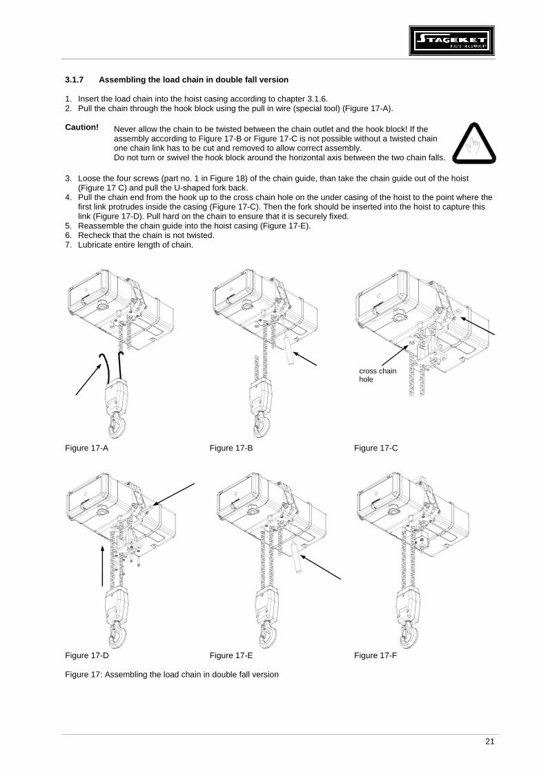
3.1.7 Assembling the load chain in double fall vers ion 1. Insert the load chain into the hoist casing according to chapter 3.1.6. 2. Pull the chain through the hook block using the pull in wire (special tool) (Figure 17-A). Caution! Never allow the chain to be twisted between the chain outlet and the hook block! If the
assembly according to Figure 17-B or Figure 17-C is not possible without a twisted chain one chain link has to be cut and removed to allow correct assembly. Do not turn or swivel the hook block around the horizontal axis between the two chain falls.
3. Loose the four screws (part no. 1 in Figure 18) of the chain guide, than take the chain guide out of the hoist
(Figure 17 C) and pull the U-shaped fork back. 4. Pull the chain end from the hook up to the cross chain hole on the under casing of the hoist to the point where the
first link protrudes inside the casing (Figure 17-C). Then the fork should be inserted into the hoist to capture this link (Figure 17-D). Pull hard on the chain to ensure that it is securely fixed.
5. Reassemble the chain guide into the hoist casing (Figure 17-E). 6. Recheck that the chain is not twisted. 7. Lubricate entire length of chain.
Figure 17-A Figure 17-B Figure 17-C
Figure 17-D Figure 17-E Figure 17-F Figure 17: Assembling the load chain in double fall version
cross chain hole

22
3.1.8 Replacing the load chain, the chain guide and the hold down Caution!
The chain guide and the hold down must also be changed when the load chain is being replaced.
3 2 1
Figure 18: Replacing the load chain, the chain guide and hold down Assembly instructions: 1. Let worn chain move out. 2. Loosen screws (1). 3. Take out chain guide (2). 4. Press the hold down (3) out, using a screwdriver. 5. Put a new hold down in by turning it through the groove over the sprocket wheel. 6. Push chain guide in and tighten the screws. Fit new chain in single fall or double fall designs as described in the
preceding section. 3.1.9 Lift limiter The lift limiter is used as the lower limit for the load hook position and has to prevent the running out of the dead end of the chain. The lift limiter is an emergency stop and cannot be used regularly as an operational limit switch. If the lift limiter has a vulcanised metal washer, then this should be mounted towards the electric chain hoist body.
3.2 Electric connections The electrical installation must comply with the relevant regulations. After having completed the installation checks have to be executed in accordance with the EN 60204-32:2008, section 19 or national regulations. Details of the control can be seen in the wiring diagram. The electric installation of the chain hoist complies with the currently valid EN 60204-32:2008.
3.2.1 Mains power The main incoming line conductor must be able to be disconnected at all poles by means of a mains switch in accordance with EN 60204-32:2008 section 5.3. The installation of this switch is operator’s responsibility. Work on the electric installation may only be carried out by trained specialists. The equipment must first be disconnected from the mains power supply and to be secured against unauthorized switch operations.

23
Fuses (slowly blowing) at 400 V (3 phase) in front o f main switch:
M 3~
380 - 415 V / 50 Hz 440 - 480 V / 60 Hz main fuse pow er cable
max. P [kW] I [A] max. P [kW] I [A] [A] A [mm²] L max .[m]
63G2 0.7 1.6 0.84 1.6 6 1.5 220
63G4 0.37 1.1 0.44 1.1 6 1.5 220
71G2 1.1 2.4 1.3 2.4 6 1.5 220
71G4 0.75 1.9 0.9 1.9 6 1.5 220
80G2 2.2 4.6 2.6 4.6 10 1.5 130
80K4 1.5 3.4 1.8 3.5 6 1.5 220
Table 4: Fuses at 380-415 V / 50 Hz and 440-480 V / 60 Hz
M 3~
220 - 240 V / 50 Hz 250 - 275 V / 60 Hz main fuse pow er cable
max. P [kW] I [A] max. P [kW] I [A] [A] A [mm²] L max .[m]
63G2 0.7 2.8 0.84 2.8 6 1.5 120
63G4 0.37 1.9 0.44 1.9 6 1.5 120
71G2 1.1 4.1 1.3 4.1 10 1.5 70
71G4 0.75 3.4 0.9 3.3 6 1.5 120
80G2 2.2 8.1 2.6 9.7 20 1.5 30
80K4 1.5 5.9 1.8 6.1 16 1,5 40
Table 5: Fuses at 220-240 V / 50 Hz and 250-275 V / 60 Hz Check if the mains voltage complies with that specified on the type plate. Connect mains supply lines and control line in accordance with wiring diagram. The L1, L2, L3 and PE terminals for the mains connection are located under the cap for gear cover. The line 3 + PE cable (minimum cross section 1.5 mm2) are necessary for the connection.
After connection, press the lifting button. If the load moves downwards, swap L1 and L2 supply wires. The mains supply must be turned off! If the control is equipped with an emergency stop according to EN 60204-32:2008 it will be a red mushroom-shaped button on the pendant. In accordance with European regulations the main switch has to be installed in addition to the emergency stop. The main switch has to be switched off and has to be returned off after daily operation.
The use of the emergency stop does not constitute the correct shutting down of the equipment. The connection terminals for the control cable and the electric trolley are located under the gear cap. The polarity of the supply network phases must be set for clockwise (right turning) rotation. If they are incorrectly set, the hoist will operate in reverse and will lift when the “Down” button on the controller is pressed. Please ask your electrician to set the power supply correctly. The polarity of the supply network is correct if the hoist will lift the load upwards when the “Up” - button is pressed. 3.2.2 Operating voltages The standard power supply of the electric chain hoists is 400 volts, 3 phases, 50 Hz. The electric chain hoists are suitable for the operation with a voltage range of 380 - 415 volts, 3 phases, 50 Hz. Different voltages and frequencies are available on request. They are marked on the motor plate.

24
3.2.3 Direct control The controlling of the motor is directly carried out by the control pendant. Gear cap Cable gland for motorized trolley Cable gland for mains supply Cable gland for control cable
Brake contactor or current contactor Rectifier Terminal block board Cap for gear cover
Figure 19: Direct control 3.2.4 Low voltage control The control occurs in a control circuit, which receives its 24 V control voltage by a control transformer. Other control voltages are available on request. If the control is equipped with an “emergency stop” in accordance with DIN EN 60204-32:2008, an additional contactor is also located in the control box and the “emergency stop” button is fitted on the control pendant. The control contactors are easily accessible on a console under the cap for control. The limit switches for lifting and lowering are situated under the cap for brake. Cable gland for motorized trolley Cable gland for mains supply Cable gland for control cable (not shown) Control transformer Rectifier Fuses secondary 1.25 A and primary 1.25 A
Contactors Terminal block board Cap for gear cover
Figure 20: Low voltage control

25
3.2.5 Electrical limit switches for lift limiting The electric chain hoists with low voltage control will be equipped with electric limit switches for lift limitation of the highest and lowest load position on request. These limit switches are operated by two buttons, protruding out of the chain guide, which can be activated either by the hook (top limit) or lift limiter (bottom position). During first operation it has to be checked that the symbols on the control pendant are in accordance with the moving direction of the load hook (see chapter 3.2.1) and that the movement will be safety stopped by switching the relevant limit switch.
Pin of limit switch for lowering Pin of limit switch for lifting
Brake Limit switches lifting Limit switches lowering
Figure 21: Electric limit switches 3.3 Configuration of electric chain hoists accordin g to DGUV V17 (BGV C1) All electric chain hoists according to DGUV V17 (BGV C1) can be applied in normal (upright) or inverted use.
• Emergency stop according to EN 60 204-32:2008 to interrupt all power operated movements • Two independently from each other operating brakes according to DGUV V17 (BGV C1) §8 (2) • Mechanic or electronic slack chain prevention, to avoid slack chain in case of unexpected strain relief; switching
point ca. 10% of nominal load according DGUV V17 (BGV C1) §8 • Electronic overload protection to switch off lifting at more than 120 % of the rated load • Operating limit switch according to DGUV V17 (BGV C1) §8:
- for version with external operating limit switch The limit switch ‘lifting’ is activated by an additional limit switch assembled on load chain.
- for version with gear limit switch: The gear limit switches for ‘lifting’ and ‘lowering‘ are assembled near the braking magnet. The acting points are adjustable.
- for version with incremental encoder • The incremental encoder for lifting and lowering is assembled near the braking magnet (alternatively or additional
to the gear limit switch).
• Emergency limit switch according to DGUV V17 (BGV C1) §8
• When using external limit switches the additional assembled lift limiter activates the emergency limit switch for lifting if the operating limit switch was passed.
• If the operating limit switch for lowering was passed the lift limiter runs onto the hoist casing and the sliding clutch acts like an emergency stop.
• Thermal overload device to protect the lifting motor for impermissible overheating (optional accessory). The thermal overload device interrupts the current supply of the emergency stop contactor and switches back after cooling time automatically. To restart the chain hoist the green button designation ‘ON’ has to be pressed.
• The sliding clutch, used in all hoists, prevents the overload of the chain hoist and of the facilities. Due to the
configuration of the sliding clutch the function of the brakes is not affected.

26
3.4 Limit switches in upright use Available equipment Required function
Four-traced gear limit switch Four-traced gear limit switch and two external limit switches
Operation limit switch for lifting Gear limit switch BO Gear limit switch BO
Operation limit switch for lowering Gear limit switch BU Gear limit switch BU
Emergency limit switch for lifting Gear limit switch NO External limit switch
Emergency limit switch for lowering Gear limit switch NU External limit switch
3.5 Limit switches in inverted use If the electric chain hoist is applied in inverted use the chain leaves and enters the electric chain hoist at the top.
For the assembly of the electric chain hoist the load hook at the end of the load chain has to be fixed on the suspension and the hoist “climbs up”. Is it not necessary to do maintenance works on a catwalk, because the electric chain hoist can be lowered down to the deepest load position. Only the test of the load hook must be done at the suspension point and the lubrication of the load chain must take place over the full length of the chain. The chain guide plate is assembled onto the chain guide to divert the outgoing chain safely into the chain box. All limit switches have to be gear limit switches. The lift limiter has to be assembled approximately 0.5 m from the end of the chain. Therewith it is ensured, that enough chain weight for moving the chain safely into the chain box is left over, even if the hoist has reached its lowest lifting position. Available equipment Required function
Four-traced gear limit switch
Operation limit switch for lifting Gear limit switch BO
Operation limit switch for lowering Gear limit switch BU
Emergency limit switch for lifting Gear limit switch NO
Emergency limit switch for lowering Gear limit switch NU
3.6 Operation and emergency limit switches 3.6.1 Gear limit switches There are four-traced gear limit switches available as standard, but for special constructions are six-traced gear limit switches too. The ON/OFF- positions are adjustable. If a four-traced gear limit switch is fitted, one lifting and one lowering position are used for the operation (BU and BO) and the other two positions for the emergency limits (NU and NO). The low voltage control panel contains two buttons to bridge the operation limit switches to allow the hook or end stop reaching the ultimate positions to be able to adjust these positions on the limit switch or to test this unit (see wiring diagram). It has to be observed, that after having actuated the emergency limit switch for lifting, the hoist can be reset from end position as follows: • Press the green button “ON” on the control pendant. • Press the “DOWN”-button until the hoist leaves the end position. These steps have to be executed by a trained specialist during testing of emergency limits or after having hit an emergency limit switch.

27
Sprocket wheel Adapter Adjusting worm screw for four traces, Contact-/trace configuration according to wiring diagram
Figure 22: Gear limit switch as operation and emergency limit switches
S10 Gear limit switch for lifting as operation limit switch S11 Gear limit switch for lowering as operation limit switch S14 Override switch S15 Override switch
Figure 23: Override switches for operation limit switches Adjustment of gear limit switches: Lifting (NO, BO): Turn adjusting worm screw clockwise → Highest hook position will be higher Lowering (NU, BU): Turn adjusting worm screw clockwise → Lowest hook position will be lower 3.6.2 External emergency limit switches
Pin of limit switch for lowering Pin of limit switch for lifting
Figure 24: External emergency limit switches Caution!
The emergency limit switches should not be used as operation limit switches. This unit will be actuated by the load hook or by an additional lift limiter mounted on the load chain.
It is available in addition to an internal operation limit switch for ultimate lift limiting. This switch is electrically connected to the emergency contactor. If this limit has been hit, only lowering will be possible, if the button for lowering and the green “ON” – button at the pendant (if included in the delivery) is pressed at the same time. A trained specialist has to be called in to double-check why the operation limit switch has failed.

28
3.7 Incremental encoder This assembly group can be fitted to all hoists for normal (upright) or inverted use. The incremental encoder provides impulses depending on the revolutions of the sprocket wheel, which can be read by a special control circuit or a computer control. The standard incremental encoder provides 100 impulses per revolution. Incremental encoders can be fitted additionally onto the extended shaft of a gear limit switch. Sprocket wheel Incremental encoder
Figure 25: Sprocket wheel with fitted incremental encoder Sprocket wheel Gear limit switch Incremental encoder
Figure 26: Sprocket wheel with fitted gear limit switch and incremental encoder

29
3.8 Mechanical underload protection Limit switch
Suspension point
Suspension eye
Electric chain hoist
Pressure spring
Nut for adjustment of underload
Load centre of gravity
Figure 27: Construction and function of mechanical underload protection The suspension eye is fixed at the electric chain hoist. It can move up and down at one bolt to indicate the load and swivels around the other bolt. The pressure springs will be adjusted by self-locking nuts. If the load on the hoist is less than the set value the suspension eye will swivel around one suspension bolt and activate a limit switch on the opposite side. This switch cut off the power for lowering. The spring loaded underload protection is adjusted on approximately 10-15% of the nominal load by the manufacturer. After operation of the underload protection a lifting movement will still be possible to move out of a dangerous condition. For set up mode without load the override switch and the function switch ‚lowering‘ must be pressed simultaneously.
Caution! The operation of the override switch is allowed in set up mode only.

30
3.9 Electronic overload and underload protection Integrated load sensor
Figure 28: Integrated load sensor Suspension point Load centre of gravity
Suspension eye with load sensor Load sensor Electric chain hoist
Figure 29: Suspension eye with load sensor
Adjusting screw for lifting Adjusting screw for lowering
Figure 30: Comparator

31
The indirect acting overload and underload protection measures the load by means of an sensor and switches off the control path for lifting (in case of overload) or lowering (in case of underload). The threshold values can be adjusted by means of adjusting screws: Left turn: Right turn:
LED on LED off
Threshold values higher Threshold values lower
The current status is shown as follows: Overload ready: Underload ready:
LED on LED off
Overload trip: Underload trip:
LED off LED on
Selection criteria of load sensing equipment Type Integrated load sensor Suspension eye with load sensor Benefit Additional protection against inner overload (chain
jam) Additional protection when approaching the gearbox with the hook tackle or hook block
Registration of all loads hanging underneath the sprocket wheel; Mass of chain does not falsify measuring result
Disadvantage Registration of all loads hanging underneath the sprocket wheel; Weight of long chain falsifies measuring result
No protection against inner overload Cable between suspension eye and chain hoist may be accident-sensitive
Applications
Mobile applications without overlong chains Fixed installation with load indication

32
3.10 Control pendant
Figure 31: Control pendant A: Emergency stop The red mushroom button switches off the control and all working movements.
B: Power supply „ON“ (After switching on the main switch for the whole lifting system.) After an emergency limit switch has been actuated or after the emergency stop has been pressed the power can be switched on again with this button. If an emergency limit switch has been actuated the operation limits have to be inspected by a specialist and the cause for the malfunction has to be rectified. After actuating an emergency limit switch and switching on the power the hoist can only be operated into the opposite direction.
C: Bridging slack chain prevention To lower load by pressing this button and lowering if the hook is underloaded or with less than 10-15% of the nominal load (lifting movement will be possible) (especially for setting a scenery) The switch ‘override underload’ should be used for lowering movement without load in set up mode.. After set up and release of the override switch the function ‘lifting’ is possible only to move out of the set up position. D: Button for lifting the load E: Button for lowering the load
Emergency stop A (empty) Power supply “ON” B Override underload C Lifting D Lowering E

33
4 Electric chain hoist with trolley 4.1 Types of trolleys All trolleys are suitable for • flanges with small width in accordance with DIN 1025 and European regulations 24-62 • flanges with medium width in accordance with DIN 1025 • flanges with large width in accordance with DIN 1025
Caution ! Elastic bumpers, with contact area at approximately the centre of the running wheels, must
be mounted as limit stops at each end of the track. Additionally the trolley can be fitted with an electric cross limit switch. Actuating bars at the travelling girder must be installed by the user.
Push trolley Electric trolley with low voltage control
2 4 3
5 2 3 4 1
Push trolley with one suspension bolt (crane component)
Electric trolley with one suspension bolt and low voltage control (crane component)
1 Travel motor 2 Connecting bolt 3 Distance washers 4 Suspension eye 5 Low voltage control (optional)
2 4 3 5 2 4 3 1 Figure 32: Trolleys 4.2 Permissible curve radius Trolleys with max. load-double fall (kg) Chain dimension (mm) Radius of curve (m) up to 2000 4x12, 5x15, 5.2x15, 7x22, 7.2x21 1
up to 3200 7x22, 7.2x21, 9x27 1.5
up to 6300 11.3x31 2
Table 6: Curve radius Caution!
If the electric trolley has to run along curves the travel motor has to be assembled at the outer side of the curve at all times.

34
4.3 Horizontal movement of electric chain hoists If electric chain hoists are suspended on electric trolleys, the equipment has to be set up in a way that collisions between the crane and other parts of the crane environment are prevented.
For trolleys equipped with electric limit switches, the actuating bars have to be installed in such a manner by the user, that the travelling movement is stopped securely before the trolley hits the end rail stoppers or buffers.
If two or more hoists are operating on the same girder with one load suspended on common load hooks, the trolleys have to be connected with a distance rod to prevent a collision of the trolleys.
Electric chain hoists with motorised horizontal move ments: Please make sure that only trolleys or other machines are used which are suitable and approved for the required load capacity.
4.4 Attachment of lightening devices to electric ch ain hoists Lightening devices and their corresponding structures have to be attached from special scaffolds, approved working platforms or similar safe positions only.
4.5 Mechanical assembly 4.5.1 Assembly position of the trolley on the elect ric chain hoist Version with direct control Version with low voltage control
Travel motor Cable for travel motor supply Cable for low voltage control of trolley Mains cable
Cable for travel motor
Figure 33: Assembly position of the trolley

35
4.5.2 Assembly of the trolley with two connecting b olts The two trolley connecting bolts are to be fixed to the lateral boards so as to allow a clearance of one to two millimetres between the running wheel flange and the girder flange. The width is adjusted by inserting spacing washers symmetrically . The suspension eye is mounted between the spacing bushes on the trolley connecting bolts. Tighten the nuts of the connecting bolts with a torque wrench.
Hexagon nuts Tightening torque (Nm) M16×1.5 75 Nm
M22×1.5 150 Nm
M36×1.5 560 Nm
Table 7: Tightening torques
Figure 34: Flexibility between chain hoist and trolley Caution!
Movement in the directions shown by the arrows must be possible between the hoist and the trolley when assembly is complete. The suspension eye must be selected in accordance with the particular type of chain hoist and the assembled trolley (flange width).
4.5.3 Assembly of the trolley with tandem trolley
Tandem trolley Strainer strap
Figure 35: Electric chain hoist with tandem trolley Caution!
Tandem trolleys are not suitable for trolleys with one suspension bolt. Tandem trolleys are not suitable for curved beams.
36
4.5.4 Assembly of the trolley with one connecting b olts One trolley connecting bolt is to be fixed to the lateral boards so as to allow a clearance of one to two millimetres between the running wheel flange and the girder flange. The width is adjusted by inserting spacing washers symmetrically . Tighten the nuts of the connecting bolts with a torque wrench. Take care, that the spacing bushes shall not be braced! The relevant tightening torques are listed in Table 7.
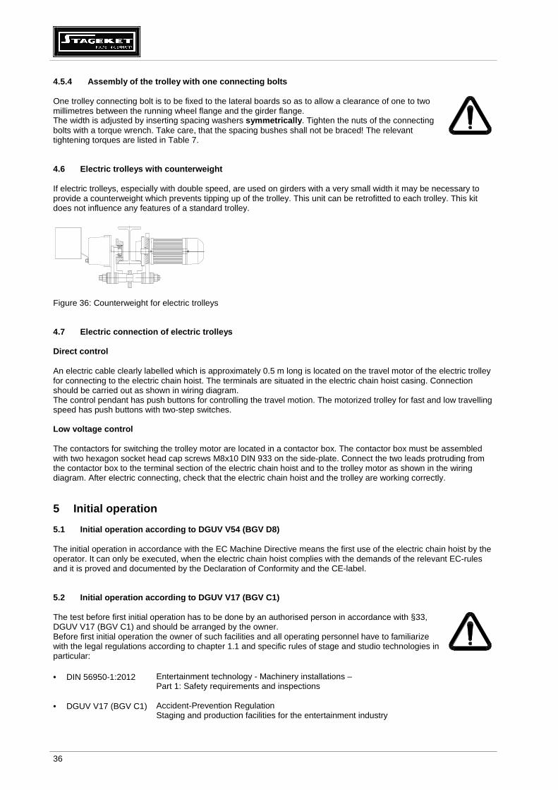
4.6 Electric trolleys with counterweight If electric trolleys, especially with double speed, are used on girders with a very small width it may be necessary to provide a counterweight which prevents tipping up of the trolley. This unit can be retrofitted to each trolley. This kit does not influence any features of a standard trolley.
Figure 36: Counterweight for electric trolleys 4.7 Electric connection of electric trolleys Direct control An electric cable clearly labelled which is approximately 0.5 m long is located on the travel motor of the electric trolley for connecting to the electric chain hoist. The terminals are situated in the electric chain hoist casing. Connection should be carried out as shown in wiring diagram. The control pendant has push buttons for controlling the travel motion. The motorized trolley for fast and low travelling speed has push buttons with two-step switches. Low voltage control The contactors for switching the trolley motor are located in a contactor box. The contactor box must be assembled with two hexagon socket head cap screws M8x10 DIN 933 on the side-plate. Connect the two leads protruding from the contactor box to the terminal section of the electric chain hoist and to the trolley motor as shown in the wiring diagram. After electric connecting, check that the electric chain hoist and the trolley are working correctly.
5 Initial operation 5.1 Initial operation according to DGUV V54 (BGV D8) The initial operation in accordance with the EC Machine Directive means the first use of the electric chain hoist by the operator. It can only be executed, when the electric chain hoist complies with the demands of the relevant EC-rules and it is proved and documented by the Declaration of Conformity and the CE-label. 5.2 Initial operation according to DGUV V17 (BGV C1) The test before first initial operation has to be done by an authorised person in accordance with §33, DGUV V17 (BGV C1) and should be arranged by the owner. Before first initial operation the owner of such facilities and all operating personnel have to familiarize with the legal regulations according to chapter 1.1 and specific rules of stage and studio technologies in particular:
• DIN 56950-1:2012 Entertainment technology - Machinery installations –
Part 1: Safety requirements and inspections
• DGUV V17 (BGV C1) Accident-Prevention Regulation Staging and production facilities for the entertainment industry

37
6 Tests The use of the electric chain hoists is possible in accordance with: • DGUV V54 (BGV D8) - Accident prevention regulations „Winches, lifting and pulling equipment“ • DGUV V17 (BGV C1) - Accident prevention regulations „Winches, lifting and pulling equipment“ • DGUV V52 (BGV D6) - Accident prevention regulations „Cranes“ The dynamic and static tests are accomplished according to EC Machinery Directive by manufacturer. The factory test is certified in the Inspection book. The user of the chain hoist has to determine the test before initial operation and the regular tests.
6.1 Test when used according to DGUV V54 (BGV D8) §23 - Winches, lifting and pulling equipment A trained specialist must test the equipment before starting operation for the first time and after extensive alterations. 6.2 Test when used according to DGUV V52 (BGV D6) §25 - Cranes An authorised person must test the cranes before starting operation for the first time and after extensive alterations. The electric chain hoists are type tested. 6.3 Regular tests • A trained specialist must test the equipment, cranes and supporting structures minimum once a year. It may be
necessary to carry out tests more often if the operating conditions are very harsh, that means for example high percentage of use with full load, dusty or aggressive environment, high duty rate, high number of operation cycles.
• Only an authorised person appointed by the Employer's Liability Insurance Associations and experts from the Technical Control Association (TÜV) are considered to be qualified to test cranes.
• Trained specialists are highly qualified specialist personnel or the manufacturer’s after-sales service personnel. 6.4 Additional tests according to DGUV V17 (BGV C1) Electric chain hoists should be tested in accordance with Accident Prevention Regulation DGUV V17 (BGV C1) and DGUV G315-390 (BGG 912). Maintenance work on electric chain hoists has to be carried out by trained specialists only. The main switch has to be switched off and the working area is to be secured beforehand.
The yearly test has to be done by trained specialists and minimum each fourth year by an authorized person (DGUV V17 (BGV C1), §34). The manufacturer recommends that test and maintenance works should be done by an authorized person due to the use of the electric chain hoists in the immediate vicinity of people or over them. In accordance with chapter 3 and following parts and assembly groups on the electric chain hoists have to be checked particularly: • The test includes the visual check for deformation and tears, the dimension check of wear and the tight fit of the
screw connections. • Function of the operation and emergency limit switches. The relevant push buttons should be pressed to bridge the
operation limit switch for check of function of the emergency limit switches NO and NU. (S13 for BO; S14 for BU) • Function and assembly of the limit switches. • Function of underload protection (slack chain prevention) at approximately 10 % of nominal load. • Check the correct running-in of the dead end of the chain into the chain box. • Check the electrical overload and underload protection; Check the integrity of all cables.

38
7 Maintenance • Trained specialists must carry out all maintenance work. • The Table 8 lists the parts and functions to be tested and the necessary maintenance work. Defects
must be rectified immediately by a trained specialist. Defects have to be reported immediately to the owner. The owner is responsible to get defects remedied by a trained specialist.
• Maintenance work may only be carried out if the electric chain hoist is not loaded and the main switch is switched off so that the power supply is disconnected.
• In case of very harsh operating conditions, e.g. multi-shift operation, high number of switching actuation, poor environmental conditions, the periods between maintenance works must be shortened.
Checking for wear • Check suspension hook and load hook for deformation (measure punch spacing) and rusting, cracks
and the general condition. • The chain sprocket in the hook block must be replaced if the running surface is worn by about 1 mm. • Check the load chain according to chapter 7.10.2 • Replace all rubber buffers if worn!
7.1 Maintenance and checks Note chapter 1 ! The following time periods are estimated, they may have to be shortened due to hard operating conditions (two or three shifts, high percentage of work with nominal load, dusty or high temperature environment) this maintenance work has to be done more frequently. Check
daily every 3 month yearly
Visual check of general condition of the equipment •
Functional check of the brake •
of the lift limiter •
Check of the brake, air gap according to 7.2 ff. •
Maintenance and adjustment of the clutch •
Wear of the load chain according to 7.10 •
Lubrication of the load chain •
Wear of the rubber elements (visual check) •
Lubrication of the hook tackle and hook block acc. to 11.3 /, check condition of the pin which prevent the hook nut from loosening and chisel punch marks •
Check condition of safety latch •
Universal checks of all screws •
hold down, chain guide, non-twisted chain •
safety devices •
Check of the condition and safe positioning of the chain box in particular the wear of the textile material
•
Check of the electric cable, power cable and pendant control •
Check of the trolleys and wheels •
Table 8: Test and maintenance works The electric chain hoist is designed in accordance with FEM 9.511. If the hoist is used under the con-ditions of FEM 9.511, including the described frequency of maintenance work, the electric chain hoist must be overhauled after 10 years.

39
7.2 Single brake 7.2.1 Description of the single brake Label / Type plate Magnetic coil
Distance bush Flange Hub Rotor with brake lining Fastening screws
Air gap SL Spring Anchor plate
Figure 37: Construction of the brake 7.2.2 Replacement of the brake Caution!
All assembly and disassembly works should be done without load. The electric chain hoist should be completely disconnected from power (Power off).
1. Loose screws of cap for gear cover. 2. Remove cap for gear cover. 3. Disconnect brake cables. 4. Loose screws of cap for brake. 5. Remove cap for brake. 6. Loose the three fastening screws of brake unit. 7. Remove worn out brake unit from the hub. 8. Fit new brake unit onto the motor shaft. 9. Fit the brake unit using the three cylindrical screws. 10. Tighten the screws evenly (tightening torques see table). 11. Connect brake cables according to wiring diagram. 12. Replace cap for gear cover and cap for brake. Type Brake Type Screws
DIN 912 Tightening torque [Nm]
Coil resistance R20 nominal [Ω]
Air gap SL
nominal [mm] Air gap SL maximal [mm]
SK02../... SK03../...
BFK 457-06 3×M4 2.8 2101 0.2 0.5
SK05../... SK07../... BFK 457-08 3×M5 5.5 1681 0.2 0.5
Table 9: Data of the brake Caution!
For order of spare parts the complete type of the electric chain hoist has to be submitted.

40
Casing Motor shaft with hub, clutch spring and nuts Brake 3 fastening screws
Figure 38: Assembly of the brake 7.3 Double brake SK 02../... and SK03../... 7.3.1 Description of the double brake
Air gap SL Anchor plates Label / Type plate Magnetic coil Rotor with brake lining Motor shaft with hubs Flange Fastening screws
Figure 39: Construction of the brake 7.3.2 Replacement of the brake Caution!
All assembly and disassembly works should be done without load. The electric chain hoist should be completely disconnected from power (Power off).
1. Loose screws of cap for gear cover. 2. Remove cap. 3. Disconnect brake cables. 4. Loose screws of cap for brake. 5. Remove cap for brake. 6. Loose the three fastening screws of brake unit. 7. Remove worn out brake unit from the hub. 8. Fit new double brake unit onto the motor shaft. 9. Fit the brake unit using the three cylindrical screws. 10. Tighten the screws evenly (tightening torques see table). 11. Connect brake cables according to wiring diagram. 12. Replace cap for gear cover and cap for brake.

41
Type Operation
brake Emergency brake
Screws DIN 912
Tightening torque [Nm]
Coil resistance R20 nominal [Ω]
Air gap SL
nominal [mm] Air gap SL maximal [mm]
SK02../... SK03../... BFK 457-06 BFK 458-06 3×M4 2.8 2101 0.2 0.5
Table 10: Data of the brake Caution!
For order of spare parts the complete type of the electric chain hoist has to be submitted.
Casing Motor shaft with hubs, clutch spring and nuts Operation brake Emergency brake Fastening screws
Figure 40: Assembly of the brake 7.4 Double brake SK 05../... and SK07../... 7.4.1 Description of the double brake
Air gap SL Anchor plate Distance bush Friction plate Label/Type plate Motor shaft with hubs Rotor with brake lining Pressure spring Threaded bolt Magnetic coil Self-locking nuts
Figure 41: Construction of the brake

42
7.4.2 Replacement of the brake Caution!
All assembly and disassembly works should be done without load. The electric chain hoist should be completely disconnected from power (Power off).
Low voltage control 1. Loose screws of cap for gear cover. 2. Remove cap. 3. Disconnect brake cables. 4. Loose screws of cap for brake. 5. Remove cap. 6. Pull the cables of brake out of the cable duct of casing.
Direct control 1. Loose screws of cap for brake. 2. Remove cap. 3. Disconnect brake cables. Continue with point 7.
7. Loose the self-locking nuts of brake unit. The threaded bolts still remain in the motor cover. 8. Remove worn out brake unit. 9. Fit new double brake unit onto the motor shaft. 10. Fit the brake unit using the self-locking nuts. 11. Tighten the nuts evenly (tightening torques see table). 12. Connect brake cables according to wiring diagram. 13. Replace caps. Type Operation
brake Emergency brake
Self-locking nuts
Tightening torque [Nm]
Coil resistance R20 nominal [Ω]
Air gap SL
nominal [mm] Air gap SL maximal [mm]
SK05../... SK07../... BFK 457-08 BFK 457-08 3×M5 5.5 1681 0.2 0.5
Table 11: Data of the brake Caution!
For order of spare parts the complete type of the electric chain hoist has to be submitted.
Casing Motor shaft with hubs, clutch spring and nuts Operation brake Emergency brake Self-locking nuts
Figure 42: Assembly of the brake

43
7.5 Electric control of the brake Mode of functioning The disk brake is supplied through a rectifier circuit. It operates according to the fail-safe principle. If there is a power failure, the brake acts automatically so that the load is held securely in every position. To shorten the braking time the brake is operated in a DC circuit. The different methods of connection in direct control and low voltage control can be seen in the respective wiring diagram. 7.6 Troubleshooting on the brake
Faults Causes Remedy
Brake does not release, air gap is not zero
Coil has contact to ground or between the windings
Replace the brake
Wiring wrong or defect
Check and correct wiring
Rectifier defective or wrong Compare wiring at rectifier with wiring diagram; especially correct setting of the bridge. Measure DC – voltage between terminals 5 and 6. If differences occur change the rectifier
Air gap too large
Replace the brake
Table 12: Troubleshooting and fault elimination If rectifier defects occur repeatedly, the brake shall be replaced even if no winding short circuit can be detected. Defect may occur only in warm operating condition. 7.7 Functional check of the brake When braking the nominal load during lowering the brake travel shall not exceed two chain link lengths. The load shall not be stopped jerkily.

44
7.7.1 Operation and emergency brake (double brake) The operation and emergency brake operate independently. They are arranged in a row on the motor pinion shaft. The motor-sided brake is the operation brake Y1 and the cap-sided brake is the emergency brake Y2. Both brakes are DC-disk brakes acting according to the closed circuit current principle. Motor pinion shaft Rotor Motor cover Operation Emergency brake Y1 brake Y2
Figure 43: Configuration of the operation and emergency brake Operation brake Y1 The magnet coil of the operation brake Y1 gets its power supply by the rectifier. The direct current (DC) is operated by the auxiliary contacts of the contactors K2 and K3. Emergency brake Y2 The magnet coil of the emergency brake Y2 gets its power supply by the rectifier too. The rectifier is supplied by alternating current (AC) out of the motor lines (U and V) 1L1 and 1L2. Due to this AC – supply the incidence time of the emergency brake is longer than of the operation brake. Separate test of the operation and emergency brake (DGUV V17 (BGV C1) only) The DC – supply of both magnetic coils are equipped with a plug connector. These connectors are marked with “1” for the operation brake Y1and “2” for the emergency brake Y2. To check the brakes separately there is a special plug “P”. This plug is supplying DC power, when the electric chain hoist is ready for operation. • Check the operation brake Y1:
Open connector “2“ and connect this connector with the plug marked with “P”. The emergency brake will remain open and the proper function of the operation brake can be checked with nominal load. Reconnect connector “2” after this procedure.
• Check the emergency brake Y2:
Carry out the same as above but connect “P“ with supply connector “1”. The operation brake will remain open. Now the function of the emergency brake can be checked separately. The test has to be carried out with nominal load. The brake distance of the emergency brake is longer than the brake distance for the operation brake.
Caution!
Reconnect the plug connectors 1 – 1 and 2 -2 after each test.

45
7.8 Safety sliding clutch The sliding clutch is located between the rotor of the lifting motor and the main pinion shaft and transmits the driving torque. At once it limits the transmissible power depending on the set coupling torque. Hence an overloading of the electric chain hoist and crane components will be prevented.
A special advantage of the patented sliding clutch is that it is situated before the operating brake. In case of heavy wear at the clutch lining an uncontrolled downward movement of the load will be prevented, because the load can be held at every lifting point by the brake. The clutch unit acts as a dry clutch with asbestos free linings. The clutch is easily adjustable and accessible. The wear resistant special lining material does not require readjustment under normal operational circumstances. 7.8.1 Construction of safety sliding clutch
1 Motor cover 2 Pressure piece 1 3 Pressure piece 2 4 Motor pinion shaft 5 Clutch discs 1 and 2
complete with lining 6 Rotor complete 7 Brake hub
(not shown) 8 Clutch spring 9 Brake 10 Cylindrical pin
(not shown) 11 Adjusting nut 12 Counter nut 13 Cap for brake
13 12 11 8 9 3 1 2 5 4 6 5
Figure 44: Construction of the sliding clutch

46
7.8.2 Adjustment of friction torque at the safety s liding clutch Caution!
The adjustment works should be executed by trained personnel only.
1. Apply the test load =1.1 times the nominal/rated load onto the load hook or the clutch testing device. 2. Switch on the chain hoist by control pendant and check, that the test load can be lifted or the clutch testing device
shows approximately 1.3 times the nominal load. The factor 1.3 is depending on the relevant hoisting speed. 3. Lower the test load to the floor. 4. Decrease or increase clutch torque until the test load is just lifted or the clutch testing device shows the required
value. 5. Adjusting the clutch torque as follows:
a. Loosen and remove the cap for brake. b. Use two spanners to loosen the counter-tightening (12). c. Tighten (turn adjusting nut clockwise) or loosen (turn adjusting nut counter-clockwise) the pressure spring until
the required test load is just lifted or the clutch testing device shows the required value. After adjustment use two spanners to counter-tighten the two hexagon nuts.
6. Finally: Recheck the clutch torque by lifting the test load. Record the adjusting value in the inspection book of the electric chain hoist.
13 12 11 8
Tag on the magnetic coil of the brake:
Figure 45: Adjustment of friction torque of the sliding clutch The sliding clutch is set with the test load by the manufacturer. After changing or replacing the brake-clutch-group, it is not necessary to reset the clutch. A test with nominal load is required only. The original distance between the counter nut and the magnetic coil of the brake is marked on the tag of the brake. 7.8.3 Checking the release limit of the sliding clu tch during regular inspections The release limit of the sliding clutch has to be checked by a specialist during the yearly work safety inspection in accordance with DGUV V52 (BGV D6) §26 or DGUV V54 (BGV D8) §23. It should be checked whether the hoist lifts the nominal load! The hoist must not lift more, than 1.6 x nominal load. If test loads larger than nominal load are not available, then release limit of slipping clutch can be checked by a clutch testing device In this case, slipping limit should be approximately 1.3 x nominal load. After checking the release limit, verify again if the hoist lifts the nominal load. When measuring wrong release value, the sliding clutch has to be readjusted in accordance with chapter 7.8.2, and verification to chapter 7.8.3 has to be repeated. Adjustment value is to be recorded.
Einstellmaß KupplungAdjusting measure for sliding clutch
. . . . . . . mm

47
7.9 Assembly and disassembly of the brake-clutch as sembly group The brake-clutch assembly group is a separate fully closed assembly group. Caution!
All assembly and disassembly works have to be done without load. The electric chain hoist has to be switched off and disconnected from the grid. Before disassembly the electric chain hoist must be suspended in normal use (upright use) or supported horizontally. Risk of oil loss.
Disassembly of the brake-clutch assembly group 6
1 Motor cover 2 Clutch disk 1 complete 3 Clutch disk 2 complete 4 Clutch spring 5 Brake complete 6 Cylinder head screw
with spring lock washer 7 Adjusting nut 8 Counter nut 9 Rotor complete 10 Motor pinion shaft 11 Cap for brake 12 Fastening screws
11 12 8 7 4 5 1 3 9 2 10 Figure 46: Brake-clutch assembly group 1. Loose fastening screws (12) on cap of brake (11). 2. Remove the cap of brake (11). 3. Disconnect brake cable of brake and pull back it. 4. Loose cylindrical head screws (6) on motor cover (1). 5. Pull out the motor cover (1) with brake-clutch assembly group.
Caution!
The assembly has to be done in reversed order.
7.10 Load chain Hoist chains are means of load carrying which require official approval. It is, therefore, important to observe the guidelines issued by the Institution for Statutory Insurance and Prevention with regard to round steel chains in hoisting operation, the guidelines for general inspection and test specifications in accordance with DIN 685-5:1981, DIN EN 818-7:2002+A1:2008 and the accident prevention regulations in DGUV V54 (BGV D8) and in DGUV V52 (BGV D6) or equivalent regulations in the respective country. 7.10.1 Lubrication of the load chain before initial operation and during operation The links along the entire length of the load chain must be lubricated with penetrating gear lubricant oil before starting operation for the first time and during operation. The chain has to be lubricated with no load in order to get the lubricant in the contact areas between the chain links. Subsequent lubrication, whereby the links must be cleaned first, depends on the frequency of use and the operating conditions. A dry-film lubricant, e.g. lubricating varnish, graphite powder, should be used when ambient influences are conducive to wear (sand, emery).

48
7.10.2 Testing of wear and replacement of the load chain The continuous monitoring of the load chain is compulsory according to DIN 685-5:1981 and the accident prevention regulations in DGUV V54 (BGV D8), §27. The load chain must be tested before starting operation and after approx. 200 operating hours or 10,000 load cycles under normal conditions or more often under harsh and severe conditions. Testing must cover checking links, particularly at their points of contact, for wear, cracks, deformation and other damages.
The chain must be replaced: • if the nominal thickness at the points of contact is reduced by 10%, • if the chain or a link is elongated by 5 %, or an eleven links piece of chain is elongated by 2% • if the links are rigid
t = nominal length of one chain link d = nominal diameter of chain link d1, d2 = actual diameters dm =
Figure 47: Load chain dimensions Chain dimensions mm×mm 4×12 5×15 5.2×15 7×22 7.2×21 Nominal diameter of link d in mm 4 5 5.2 7 7.2
Wear limit of diameter dm in mm 3.6 4.5 4.7 6.3 6.5
Length over 1 link t in mm 12 15 15 22 21
Wear limit of length of one link (max) tmax in mm 12.6 15.8 15.8 23.1 22.1
Length over 11 links 11×t in mm 132 165 165 242 231
Wear limit of length of 11 links (max) (11×t)max in mm 134.6 168.3 168.3 246.8 235.6
Table 13: Measurement of wear Caution ! Replacement of chain shall only be done if spare parts are obtained from the manufacturer
or his approved service agent. The chain guide and hold-down must also be replaced with the chain if necessary. To replace the load chain, see chapter 3.1.6 and following.
7.11 Measuring wear and replacing load hook According to DIN 15401-1:1979 load hooks have to be replaced if the length between the chisel punch marks (dimension Y) widened more than 10 % or the load bearing section is reduced by 5 %. The permissible values are shown on the hook certificate in the Inspection book.
t 11 x t
d
d
d1
2 d1 + d2 2

49
7.12 Maintenance work on the trolleys The checks and maintenance work on the electric trolleys and push trolleys have to be done in accordance with Table 8.
7.12.1 Construction of the brake of the electric tr olley Type BFK The brake type BFK operates absolutely maintenance free.
3 pieces screws M3×8 DIN 912 at a circle diameter of 58 mm Motor pinion shaft
Figure 48: Construction of the brake type BFK Type EFB
3 1 2 6 4 5
Figure 49: Construction of the brake type EFB Caution!
If the brake linings are worn so that the air gap is about 0.9 mm it is necessary to adjust the gap.
Readjustment of the brake type EFB: 1. Dismantle the fan cover (1). 2. Loosen the fan screws (2). 3. Remove the rubber gasket (3) and put a thickness gauge 0.25 mm between the plate (4) and the
sticking plate (5). 4. Tighten the screw (6) so far that you can remove the thickness gauge easily. 5. Tighten the fan screws (2) symmetrically. Tighten first the screws opposite the key (torque 4-5.5 Nm). 6. Tighten the screw (6) again. 7. Remove the thickness gauge. 8. Assemble the fan cover (1). 9. Watch the test run of the trolley.

50
8 Duty rate of an electric chain hoist Caution!
The duty rate and the number of operating cycles in one hour must not be higher than as shown on the specification plate of the hoist or in a technical data table. (European regulation FEM 9.683).
The duty rate, expressed as the cyclic duration factor (c.d.f.) is the ratio of running time to running time + period of rest
Formula: c.d.f. % = running time x 100%
running time + period of rest
running timelifting period of rest
running timelowering period of rest
1 lifting cycle
s [m]
t [min]
The duty rate is limited by the permissible degree of heat in the lifting motor. The running time is dependent on the necessary lifting height, lifting speed of the electric chain hoist and the number of lifting motions required for a particular transport procedure (unloading trucks, feeding machines). It is difficult in practice to take note of the duty rate during the lifting operation. We, therefore, give the following practical guidelines: 8.1 Short time duty This duty type is not permissible for the slower speed of hoisting motors with two speeds. After having reached the maximum running time a break is required and the hoist can be further used in intermittent duty mode. The permissible operating periods without cooling interval when operation starts and with a motor temperature of approx. 20° C are following:
Duty group acc. to FEM 9.511
Duty group acc. to ISO 4301
Duty rate c.d.f.
Operating period * acc. to FEM 9.683 (tB in min)
1 Bm M 3 25 % 15
1 Am M 4 30 % 15
2 m M 5 40 % 30
3 m M 6 50 % 30
3 m M 6 60 % 60
* The operating periods t B of the STAGEKET chain hoists are higher than required acc. to FEM 9.683. Table 14: Duty rate for short time duty

51
8.2 Intermittent duty Operation must be interrupted whenever the highest permissible operating time is reached. The following breaks are necessary depending on the duty rate c.d.f. of the electric chain hoist:
Duty rate c.d.f. Break (min) 15 % 5 times running time 20 % 4 times running time 25 % 3 times running time 30 % 2.5 times running time 40 % 1.5 times running time 50 % 1 times running time 60 % 0.66 times running time
Table 15: Duty rate for intermittent duty 8.3 Example The electric chain hoist SK 030/52 type 500/1-8 is to lift loads of 500 kg to a height of 3 m. Performance data : load capacity 500 kg lifting speed 8 m/min – high speed; duty rate 40 % – high speed; At the beginning of the lifting operation the electric chain hoist has a temperature of approx. 20 °C.
c.d.f. = 0.75 min The hoist can be operated for approximately 30 min. without a break. This means
40 cycles x 500kg load = 20000 kg transported load. After 30 minutes of operating time, 1.5 minutes break for each minute of operating time must be taken (i.e. 3 times the operating time). This break is usually necessary for slinging and taking off loads. Caution ! Cooling periods are imperative for extreme lifting heights (from 10 metres on).
Low lifting speed should only be used for precise lowering and lifting of loads. It is not suitable when greater lifting heights shall be driven through.
Option : To protect the lifting motor a thermal overload device is offered as an option (24 Volts low voltage control is required!).
9 Duty rate of the electric trolleys If the hoist is equipped with an electric trolley the operators have to take care of the duty rating of the trolley as well. This especially applies to very long track systems. Electric trolley type Duty rate Running time (tB in min) Trolleys with a single speed 40 % 30
Trolleys with a double speeds 40/20 % 30*
* The ratings are relevant for the fast travelling speed. Table 16: Duty rate for electric trolleys
3 m (lifting) + 3 m (lowering) 8 m/min

52
10 Strainer clamp for the control cable
Control cable Strainer clamp Control pendant
Figure 50: Assembly of the strainer clamp Caution!
The strainer clamp must be fixed in such a way as to prevent any tensile forces affecting the control cable. Pulling the chain hoist at the control pendant by means of the strainer clamp is not permitted.
11 Lubricants / Auxiliary materials 11.1 Gear The gear is already filled with gear oil by the manufacturer. It is lifetime lubrication. The oil must be changed: • during general overhaul of the electric chain hoist • in case of visible leakages • in case of excessive breathing out of the gear vent • after each opening of the gear box
Caution! Make sure that the gear box is filled with the right amount of gear oil.
Change of oil: For that purpose an oil filling screw is located on the upper side and an oil draining screw is located on the bottom side of the hoist body. Gear oil specification: mineral oil; viscosity 220 mm²/s at 40°C. The amount of oil is shown in the following table: Version Amount in ml SK 020/..., SK 021/..., SK 030/..., SK 031/... 175
SK 050/..., SK 051/..., SK 070/..., SK 071/... 350
Table 17: Amount of oil

53
The following oil sorts can be used:
Supplier Oil sort Remarks
Fuchs© Renolin CLP 220
Castrol© Alpha Zn 200
ESSO© EP 220
Mobil© Mobil gear 630
Shell© Omala 220
ELF© Reductelf SP 220
BP© XP 220 BP Energol GR
Exxon Mobil© Mobilux EP2
Fuchs© Geralin SF 220 Food industry
Table 18: Oil sorts
Caution! The waste oil has to be disposed in accordance with the law of environmental protection.
11.2 Chain
Caution! Before first operation and during the operation of the electric chain hoist the chain links must be lubricated over the whole length of the chain by a creeping gear oil.
Lubrication of chain: • Lubricate chain without load. • Lubricate the shaded areas of the chain link. • Also lubricate the chain in the chain box. • Clean the chain before repeated lubrication. • The amount of lubricant and the frequency of lubrication may vary due to operating conditions. • Lubricate chain minimum each 3 month. • Shorten lubrication intervals if necessary /in dependence of operating conditions. • Use a dry-film lubricant, if the operating conditions are conducive to wear (sand, emery).
Figure 51: Lubrication of the chain
Load side

54
Following lubricants are recommended for lubrication of chain depending on operating conditions:
Supplier Lubricant Remarks
Fuchs© Stabylan 2001
Klüber© Klüberoil 4UH 1-1500 Food industry
Fuchs© Ceplattyn 300 Dry-film lubricant
Castrol© Optimol Viscogen KL300
Fuchs© Stabylan 5006
Klüber© Klüberoil CA 1-460
Fuchs© CTP D 350
Fuchs© Renolit SO-GFB
Klüber© Microlube GB 00
Table 19: Lubricants of chain 11.3 Hook block and hook tackle
Caution! Lubricate the anti-friction bearings on the hook and the chain sprocket after approx. 20,000 lifting cycles or once a year, if in heavy use shorten the interval, use a special anti-friction bearing grease.
Lubricants recommended for lubrication of bearings:
Supplier Lubricant
Fuchs© Renolit Duraplex EP2, EP3
Fuchs© Lagermeister LX EP2
Table 1: Lubricants of bearings 11.4 Trolley
Caution! The gear pinion and the geared wheels of the electric trolley have to be lubricated with roller bearing grease before first operation and once a year or after 10,000 driving cycles, if in heavy use the interval has to be shortened.
Lubricants recommended for lubrication of gearings:
Supplier Lubricant
Fuchs© Renolit Duraplex EP2, EP3
Fuchs© Lagermeister LX EP2
Table 2: Lubricants of gearing 12 Measures to be taken at the end of the S.W.P. After the hoist or its components have reached the end of the S.W.P. the hoist or its components have to be overhauled or to be taken finally out of operation. The parts have to be disposed in accordance to the laws of environment protection. Metals, rubber, plastics have to be disposed or recycled separately.

55
13 Example of Declaration of Conformity

56
14 Example of Declaration of Incorporation

57

58
The operators who have been instructed to use this hoist and have read the manual and especially the safety advice.
Name, Surname Date Signature
The advice contained in this manual is limited to such matters / facts which are necessary to ensure a safe operation and maintenance of the industrial hoists, to be observed by appropriate skilled and qualified operators. Further information about other operational conditions is not considered herewith. In case of any deviations to the normal operations (such as unusual noise, vibrations, higher input current or frequently blowing fuses) the hoist has to be taken out of operation. The area underneath the load has to be secured and blocked off; a possible fault could result in danger to people or goods. The operator or owner of the hoist has to call a trained specialist to repair the hoist.
HOFFMANN Fördertechnik GmbH Wurzen Dresdener Straße 64-68 ● 04808 Wurzen ● Deutschland
Phone: (0 34 25) 89 24 – 0 ● Fax: (0 34 25) 89 24 – 99 ● E-mail: [email protected] ● Internet: http://www.liftket.de