electric chain hoist - cheng day · 6) federation europeenne de la manutention operation cycle...
TRANSCRIPT
�Electric�Chain�Hoist
Professional��cranes��&��hoists��for��lifting
/�SH�series
CHENG��DAY��MACHINERY�WORKS�CO.,�LTD.
■�Revision�of�November�,2016�(Edition�No.2)��#950292
■ Due�to�the�printing�factors,�the�color�of�the�products�is������subject�to�minor�deviation�from�the�physical�objects.��
■�No�further�notice�while�sizes�and�dimensions�update;�����Quotations�are�based�on�practical�dimensions.
CHENG�DAY�MACHINERY�WORKS�CO.,�LTD.
No. 173, Wen Chiu Road, Dajia District, Taichung City, 437 Taiwan. Tel: +886-4-2688-1581 Fax: +886-4-2688-1509
Website: www.chengday.com.tw E-mail: [email protected]
SYSTEMS
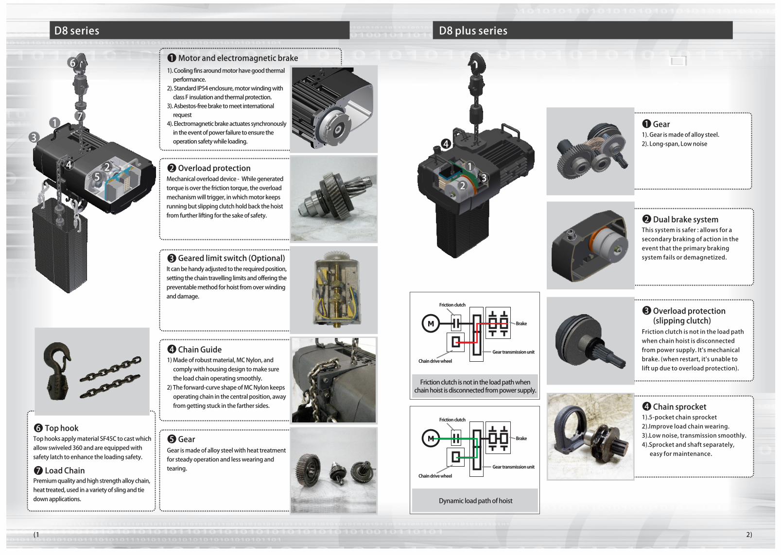
Mechanical�overload�device�-��While�generated�torque�is�over�the�friction�torque,�the�overload�mechanism�will�trigger,�in�which�motor�keeps�running�but�slipping�clutch�hold�back�the�hoist�from�further�lifting�for�the�sake�of�safety.
It�can�be�handy�adjusted�to�the�required�position,�setting�the�chain�travelling�limits�and�offering�the�preventable�method�for�hoist�from�over�winding�and�damage.
Motor�and�electromagnetic�brake
Geared�limit�switch�(Optional)�
Overload�protection
Gear�is�made�of�alloy�steel�with�heat�treatment�for�steady�operation�and�less�wearing�and�tearing.
GearTop�hooks�apply�material�SF45C�to�cast�which�allow�swiveled�360�and�are�equipped�with�safety�latch�to�enhance�the�loading�safety.
Top�hook
Premium�quality�and�high�strength�alloy�chain,�heat�treated,�used�in�a�variety�of�sling�and�tie�down�applications.
��
Load�Chain
1
1)�Made�of�robust�material,�MC�Nylon,�and������comply�with�housing�design�to�make�sure������the�load�chain�operating�smoothly.�2)�The�forward-curve�shape�of�MC�Nylon�keeps������operating�chain�in�the�central�position,�away������from�getting�stuck�in�the�farther�sides.
Chain�Guide4
3
2
56
7
4 2
6
D8�series
(1 2)
7
31
5
1).�Cooling�fins�around�motor�have�good�thermal������performance.�2).�Standard�IP54�enclosure,�motor�winding�with������class�F�insulation�and�thermal�protection.3).�Asbestos-free�brake�to�meet�international������request4).�Electromagnetic�brake�actuates�synchronously������in�the�event�of�power�failure�to�ensure�the������operation�safety�while�loading.
D8�plus�series
Friction�clutch�is�not�in�the�load�path�when�chain�hoist�is�disconnected�from�power�supply.�It's�mechanical�brake.�(when�restart,�it's�unable�to�lift�up�due�to�overload�protection).
Overload�protection�(slipping�clutch)
3
1).�5-pocket�chain�sprocket2).�Improve�load�chain�wearing.�3).�Low�noise,�transmission�smoothly.�4).�Sprocket�and�shaft�separately,�������easy�for�maintenance.
Chain�sprocket4
This�system�is�safer�:�allows�for�a�secondary�braking�of�action�in�the�event�that�the�primary�braking�system�fails�or�demagnetized.
Dual�brake�system2
1).�Gear�is�made�of�alloy�steel.�2).�Long-span,�Low�noise
Gear1
M Brake
Friction�clutch�
Chain�drive�wheel�
Gear�transmission�unit�
Brake
Friction�clutch
Chain�drive�wheel
Gear�transmission�unit
M
Dynamic�load�path�of�hoist
Friction�clutch�is�not�in�the�load�path�when�chain�hoist�is�disconnected�from�power�supply.
3
4
2
1
(3
MJ
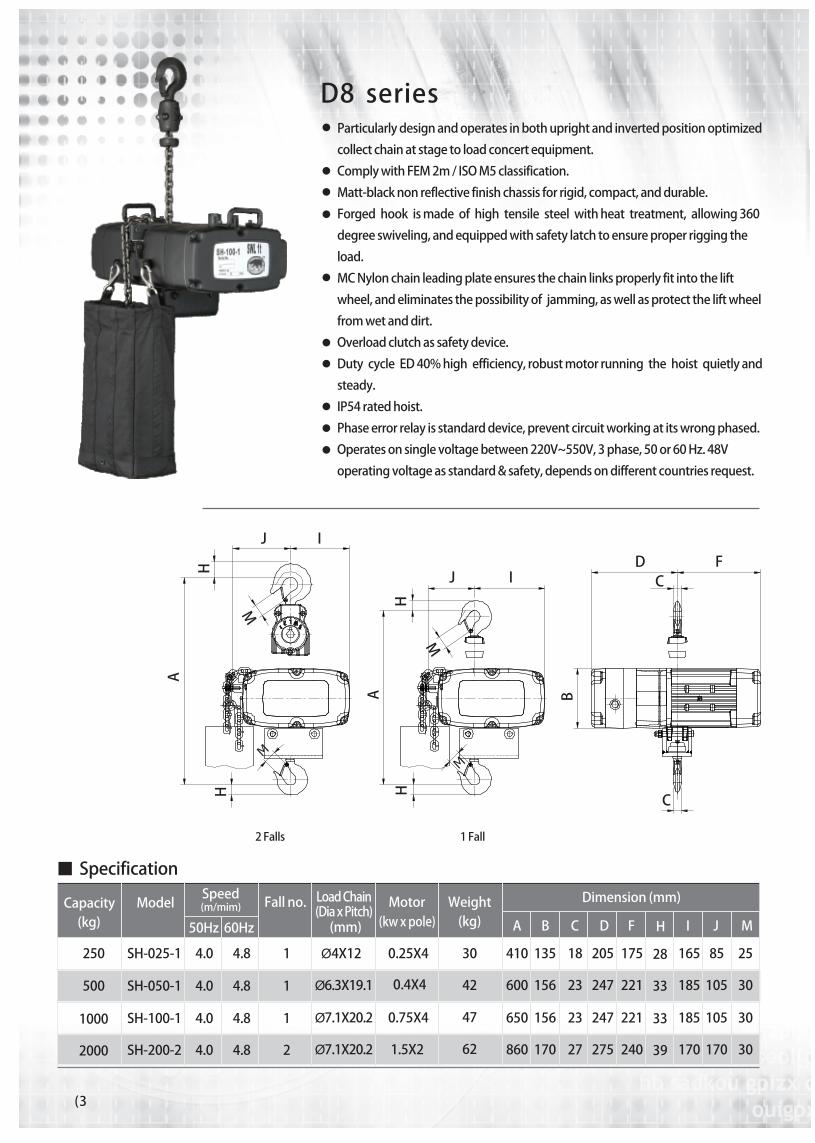
Particularly�design�and�operates�in�both�upright�and�inverted�position�optimized�
collect�chain�at�stage�to�load�concert�equipment.��
Comply�with�FEM�2m�/�ISO�M5�classification.
Matt-black�non�reflective�finish�chassis�for�rigid,�compact,�and�durable.
Forged��hook��is�made��of��high��tensile��steel��with�heat��treatment,��allowing�360�
degree�swiveling,�and�equipped�with�safety�latch�to�ensure�proper�rigging�the�
load.�
MC�Nylon�chain�leading�plate�ensures�the�chain�links�properly�fit�into�the�lift�
wheel,�and�eliminates�the�possibility�of��jamming,�as�well�as�protect�the�lift�wheel�
from�wet�and�dirt.�
Overload�clutch�as�safety�device.
Duty��cycle��ED�40%�high��efficiency,�robust�motor�running��the��hoist��quietly�and�
steady.
IP54�rated�hoist.
Phase�error�relay�is�standard�device,�prevent�circuit�working�at�its�wrong�phased.
Operates�on�single�voltage�between�220V~550V,�3�phase,�50�or�60�Hz.�48V�
operating�voltage�as�standard�&�safety,�depends�on�different�countries�request.�
IA B C D F H
25
30
30
30
85
105
105
170
165
185
185
170
28
33
33
39
250
1000
SH-025-1
SH-100-1
4.8
4.8
1
1
Ø4X12
Ø7.1X20.2
0.25X4
0.75X4
30
47
410
650
135
156
18
23
205
247
175
221
500 SH-050-1 4.8 1 Ø6.3X19.1 0.4X4 42 600 156 23 247 221
2000 SH-200-2 4.8 2 Ø7.1X20.2 1.5X2 62 860 170 27 275 240
4.0
4.0
4.0
4.0
D8��series
F
C
J I
H
A
H
M
M
A
HH
J I
M
M
DC
B
2�Falls
(kw�x�pole) (kg)(mm)
(m/mim)
50Hz 60Hz
Capacity(kg)
ModelSpeed
Fall�no. Load�Chain(Dia�x�Pitch)
Motor Weight Dimension�(mm)
1�Fall
Specification
4)
MJI(kw�x�pole) (kg) A B C D F H(mm)(m/mim)
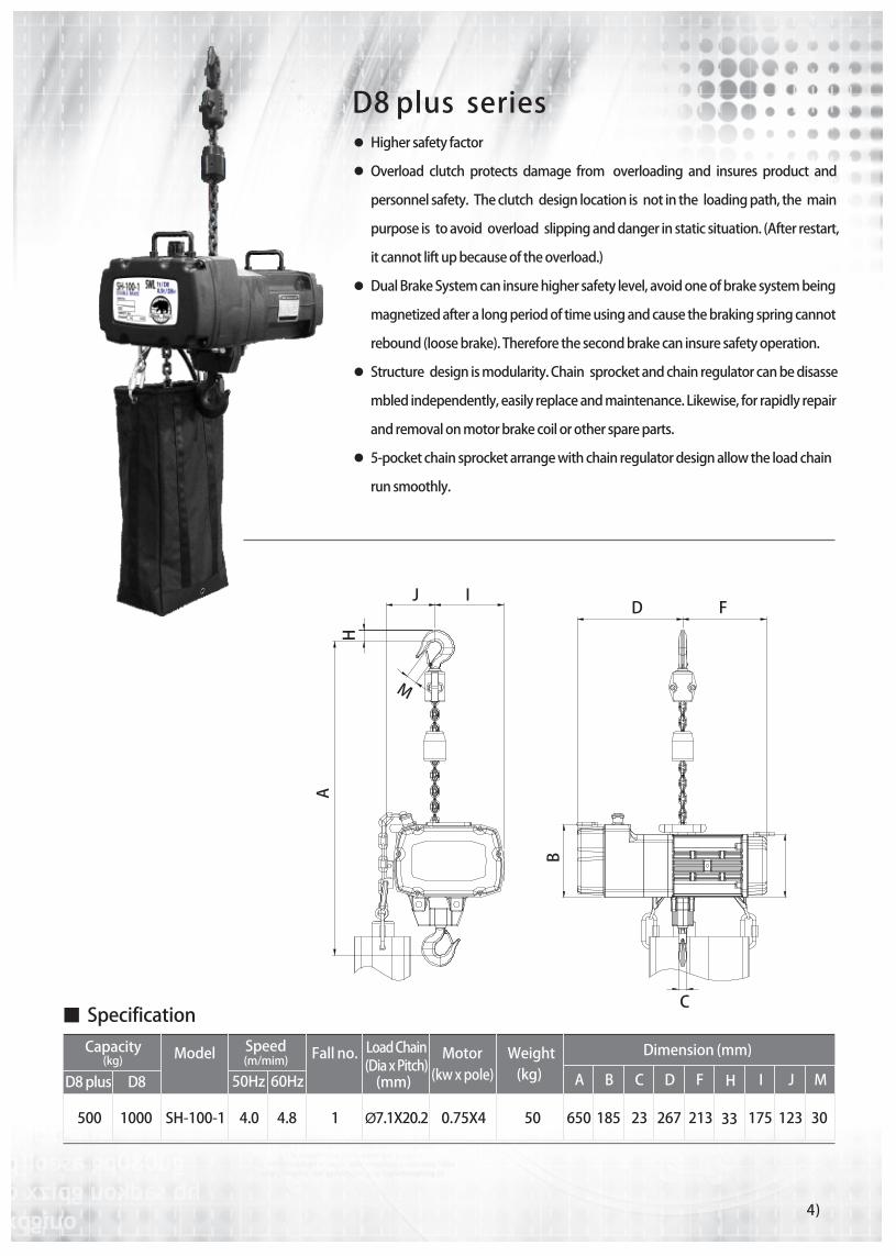
3012317533500 SH-100-1 4.8 1 Ø7.1X20.2 0.75X4 50 650 185 23 267 2134.0
50Hz 60Hz
Capacity(kg)
1000
D8�plus D8�
Specification
Model Speed Fall�no. Load�Chain(Dia�x�Pitch)
Motor Weight Dimension�(mm)
D8�plus��seriesHigher�safety�factor�
Overload��clutch��protects��damage��from���overloading��and��insures��product��and�
personnel�safety.��The�clutch��design�location�is��not�in�the��loading�path,�the��main�
purpose�is��to�avoid��overload��slipping�and�danger�in�static�situation.�(After�restart,�
it�cannot�lift�up�because�of�the�overload.)�
Dual�Brake�System�can�insure�higher�safety�level,�avoid�one�of�brake�system�being�
magnetized�after�a�long�period�of�time�using�and�cause�the�braking�spring�cannot�
rebound�(loose�brake).�Therefore�the�second�brake�can�insure�safety�operation.��
Structure��design�is�modularity.�Chain��sprocket�and�chain�regulator�can�be�disasse
mbled�independently,�easily�replace�and�maintenance.�Likewise,�for�rapidly�repair�
and�removal�on�motor�brake�coil�or�other�spare�parts.
5-pocket�chain�sprocket�arrange�with�chain�regulator�design�allow�the�load�chain�
run�smoothly.
J I
H
M
A
D F
C
B
(5
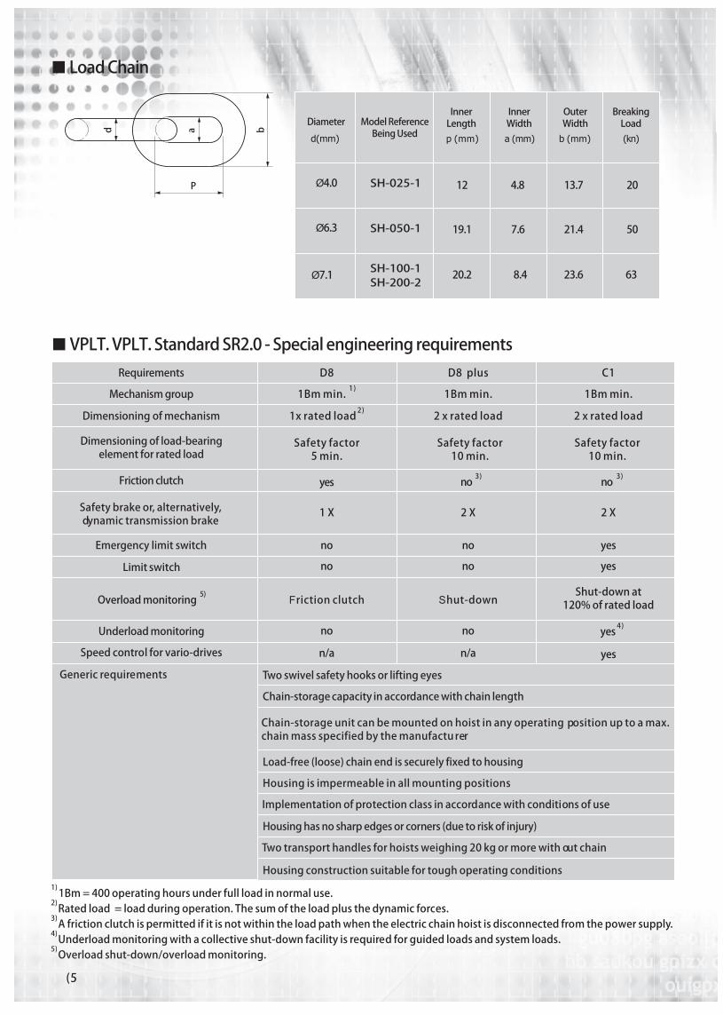
¢ Load�Chain
Ø4.0
Ø7.1
SH-025-1 12 4.8 13.7 20
Ø6.3 SH-050-1
SH-100-1SH-200-2
19.1 7.6 21.4 50
20.2 8.4 23.6 63
P
d a b
Requirements
Mechanism�group
Dimensioning�of�mechanism
Dimensioning�of�load-bearingelement�for�rated�load
Friction�clutch
Safety�brake�or,�alternatively,dynamic�transmission�brake�
Emergency�limit�switch
Limit�switch
O5)�verload�monitoring�
Underload�monitoring
Speed�control�for�vario-drives
Two�swivel�safety�hooks�or�lifting�eyes
Chain-storage�capacity�in�accordance�with�chain�length
Chain-storage�unit�can�be�mounted�on�hoist�in�any�operating�position�up�to�a�max.�chain�mass�specified�by�the�manufacturer
Load-free�(loose)�chain�end�is�securely�fixed�to�housing
Housing�is�impermeable�in�all�mounting�positions
Implementation�of�protection�class�in�accordance�with�conditions�of�use
Housing�has�no�sharp�edges�or�corners�(due�to�risk�of�injury)
Two�transport�handles�for�hoists�weighing�20�kg�or�more�with out�chain
Housing�construction�suitable�for�tough�operating�conditions
D81)
1Bm�min.�2)�1 �rated�loadx
Safety�factor5�min.
yes
1�X
no
Friction�clutch
Generic�requirements
no
no
n/a
D8��plus
1Bm�min.�2 �rated�load�x
�3 )no�
2�X
no
Shut-down
no
no
n/a
C1
1Bm�min.�2� �rated�loadx
�3 )no�
2�X
yes
Shut-down�at�120%� f�rated�loado
yes
4�) yes
yes
1)�Bm�=�400�operating�hours�under�full�load�in�normal�use1 .
2)� ated�load��=�load�during�operation.�The�sum�of�the�load�plus�the�dynamic�for es.R c3)� �friction�clutch�is�permitted�if�it�is�not�within�the�load�path�when�the�electric�chain�hoist�is�dis onnected�fr m�the�power�supplyA c o .4)� nderload�monitoring�with�a�collective�shut-down�facility�is�r quir d�for�guided�loads�and�system�lo ds.U e e a5)�Overload�shut-down/overload�monitoring.
¢ VPLT.�VPLT.�Standard�SR2.0�-�Special�engineering�requirements
p (mm) a (mm) b (mm) (kn)d(mm)
Diameter Model�ReferenceBeing�Used
Inner�Length
Inner�Width
OuterWidth
BreakingLoad
Safety�factor10�min.
Safety�factor10�min.
6)
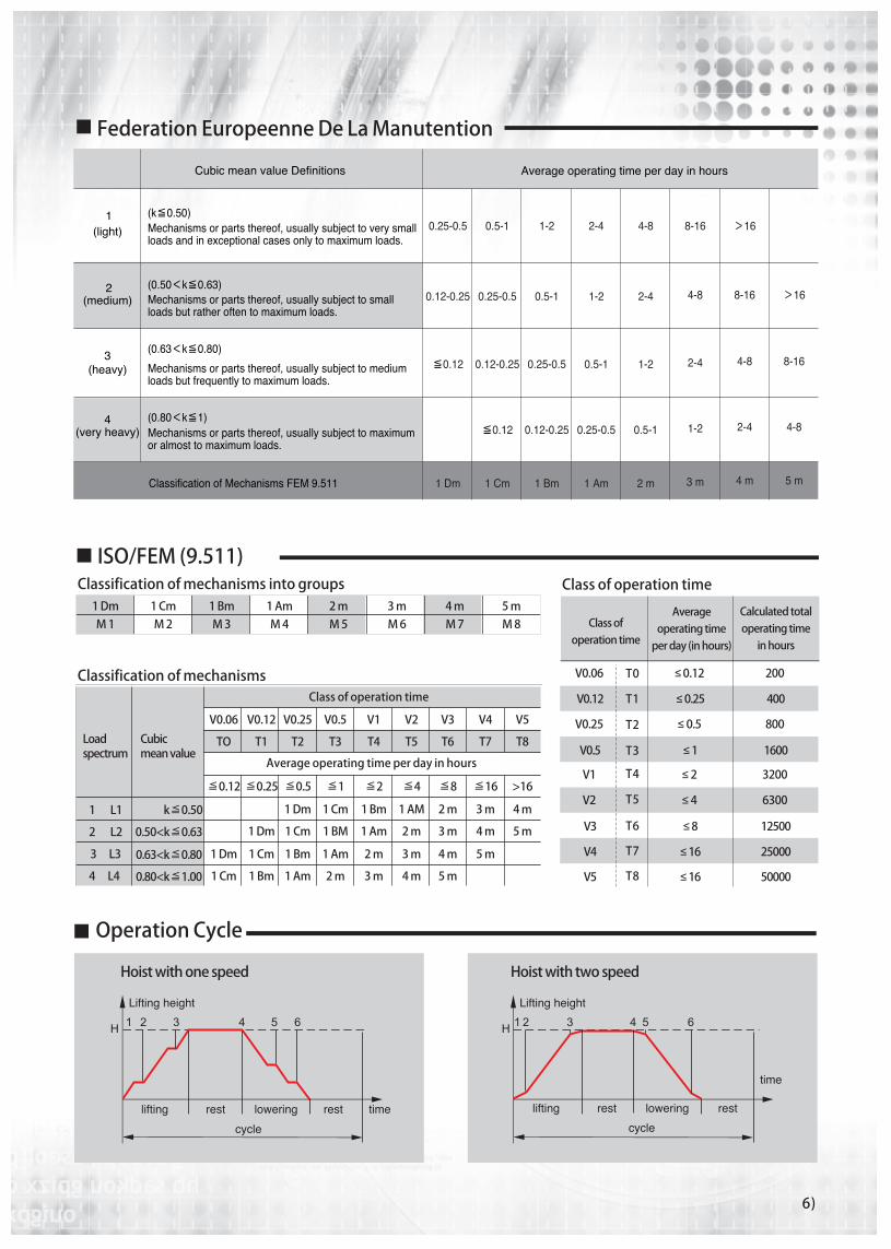
Federation�Europeenne�De�La�Manutention
Operation�Cycle
Class�of�operation�time
Hoist�with�one�speed Hoist�with�two�speed
ISO/FEM�(9.511)
V0.06
V0.12
V0.25
T1
≤�0.12
≤ 0.25
≤ 0.5
200
400
800
T0
T2
�
V0.5 ≤ 1 1600T3
V1
V3
V4
V5
≤ 2
≤ 8
≤ 16
3200
12500
25000
≤ 16 50000
T4
T6
T7
T8
V2 ≤ 4 6300T5
V0.06 V0.12 V0.25 V0.5 V1 V2 V3 V4 V5
TO T1 T2 T3 T4 T5 T6 T7 T8
≦0.12 ≦0.25 ≦0.5 ≦1 ≦2 ≦4 ≦8 ≦16 >16
1�Dm 1�Cm 1�Bm 1�AM 2�m 3�m 4�m
1�Dm 1�Cm 1�BM 1�Am 2�m 3�m 4�m 5�m
1�Dm 1�Cm 1�Bm 1�Am 2�m 3�m 4�m 5�m
1�Cm 1�Bm 1�Am 2�m 3�m 4�m 5�m
k≦0.50
0.50<k≦0.63
0.63<k≦0.80
0.80<k≦1.00
1������L1
2������L2
3�����L3
4�����L4
1�DmM�1
1�CmM�2
1�BmM�3
1�AmM�4
2�mM�5
3�mM�6
4�mM�7
5�mM�8 Class�of�
operation�time
Average�operating�time�per�day�(in�hours)
Calculated�total�operating�time�
in�hours
Classification�of�mechanisms�into�groups
Classification�of�mechanismsClass�of�operation�time
Loadspectrum
Cubicmean�value
Average�operating�time�per�day�in�hours