electra™ and ion™ - harmonic inc · divitrackmx on platforms managed by harmonic nmx™. when...
TRANSCRIPT

Electra™ and Ion™Standalone Encoder Web GUI (SAG)
Getting Started GuideVERSION 5
Rev A
Manual Part No. MAN-SAEGS-005

© 2011 Harmonic Inc. All rights reserved.
Disclaimer
Harmonic reserves the right to alter the equipment specifications and descriptions in this publication without prior notice. No part of this publication shall be deemed to be part of any contract or warranty unless specifically incorporated by reference into such contract or warranty. The information contained herein is merely descriptive in nature, and does not constitute a binding offer for sale of the product described herein. Harmonic assumes no responsibility or liability arising from the use of the products described herein, except as expressly agreed to in writing by Harmonic. The use and purchase of this product do not convey a license under any patent rights, copyrights, trademark rights, or any intellectual property rights of Harmonic. Nothing hereunder constitutes a representation or warranty that using any products in the manner described herein will not infringe any patents of third parties.
Trademark Acknowledgments
Harmonic and all Harmonic product names are trademarks of Harmonic Inc. All other trademarks are the property of their respective owners.

© 2011 Harmonic Inc. All rights reserved.
Documentation ConventionsThis manual uses some special symbols and fonts to call your attention to important information. The following symbols appear throughout this manual:
NOTE: The Note symbol calls your attention to additional information that you will benefit from heeding. It may be used to call attention to an especially important piece of information you need, or it may provide additional information that applies in only some carefully delineated circumstances.
TIP: The Tip symbol calls your attention to parenthetical information that is not necessary for performing a given procedure, but which, if followed, might make the procedure or its subsequent steps easier, smoother, or more efficient.
In addition to these symbols, this manual uses the following text conventions:
■ Data Entry: indicates text you enter at the keyboard.
■ User Interface: indicates a button to click, a menu item to select, or a key or key sequence to press.
■ Screen Output: shows console output or other text that is displayed to you on a computer screen.
■ Bold: indicates the definition of a new term.
■ Italics: used for emphasis, cross-references, and hyperlinked cross-references in online documents.

Table of Contents
© 2011 Harmonic Inc. 4 SAG, Version 5, Rev A
Table of Contents
Chapter 1 Introduction1.1 Product Overview . . . . . . . . . . . . . . . . . . . . . . . . . . . . . . . . . . . . . . . . . . 6
1.1.1 DiviTrackMX™ . . . . . . . . . . . . . . . . . . . . . . . . . . . . . . . . . . . . . . . . . . . . . 71.2 Encoding Overview . . . . . . . . . . . . . . . . . . . . . . . . . . . . . . . . . . . . . . . . . 71.3 Input-Encoding-Output . . . . . . . . . . . . . . . . . . . . . . . . . . . . . . . . . . . . . . 71.4 Input-Decoding-Encoding-Output . . . . . . . . . . . . . . . . . . . . . . . . . . . . . 8
Chapter 2 Installation and Startup2.1 Using SAG . . . . . . . . . . . . . . . . . . . . . . . . . . . . . . . . . . . . . . . . . . . . . . . 10
2.1.1 Web Browser Requirements . . . . . . . . . . . . . . . . . . . . . . . . . . . . . . . . 102.1.2 Displaying SAG . . . . . . . . . . . . . . . . . . . . . . . . . . . . . . . . . . . . . . . . . . . 112.1.3 Navigating with SAG . . . . . . . . . . . . . . . . . . . . . . . . . . . . . . . . . . . . . . 11
2.2 Installing Platform Software . . . . . . . . . . . . . . . . . . . . . . . . . . . . . . . . . 122.3 License Requirements . . . . . . . . . . . . . . . . . . . . . . . . . . . . . . . . . . . . . 132.4 What’s Next . . . . . . . . . . . . . . . . . . . . . . . . . . . . . . . . . . . . . . . . . . . . . . 13
Chapter 3 Template Configurations3.1 Using the Template Configuration. . . . . . . . . . . . . . . . . . . . . . . . . . . . 15
3.1.1 Clearing the Current Configuration . . . . . . . . . . . . . . . . . . . . . . . . . . 153.1.2 Loading the Template Configuration . . . . . . . . . . . . . . . . . . . . . . . . . 163.1.3 Completing your Configuration . . . . . . . . . . . . . . . . . . . . . . . . . . . . . . 16
Chapter 4 Electra 8000 Encoding Tutorial4.1 Configuring an Encoder with SDI Input and IP Output . . . . . . . . . . . 17
4.1.1 Creating an HD Video Stream . . . . . . . . . . . . . . . . . . . . . . . . . . . . . . 184.1.2 Adding an Audio Stream to the Program . . . . . . . . . . . . . . . . . . . . . 204.1.3 Reviewing the Video and Audio Streams . . . . . . . . . . . . . . . . . . . . . 224.1.4 Configuring the Output . . . . . . . . . . . . . . . . . . . . . . . . . . . . . . . . . . . . 234.1.5 Summary . . . . . . . . . . . . . . . . . . . . . . . . . . . . . . . . . . . . . . . . . . . . . . . . 24
4.2 Configuring a FLEX-based Encoder with IP Input . . . . . . . . . . . . . . . 254.2.1 Discovering Programs on the IP Input . . . . . . . . . . . . . . . . . . . . . . . . 264.2.2 Assigning Discovered Streams to a Decoder Port . . . . . . . . . . . . . . 284.2.3 Reviewing the Decoder Input . . . . . . . . . . . . . . . . . . . . . . . . . . . . . . . 324.2.4 Configuring the Encoder Streams . . . . . . . . . . . . . . . . . . . . . . . . . . . 334.2.5 Configuring the Output . . . . . . . . . . . . . . . . . . . . . . . . . . . . . . . . . . . . 354.2.6 Summary . . . . . . . . . . . . . . . . . . . . . . . . . . . . . . . . . . . . . . . . . . . . . . . . 36

Table of Contents
© 2011 Harmonic Inc. 5 SAG, Version 5, Rev A
Chapter 5 Electra 5000, 5400, 7000, and Ion Tutorial5.1 Configuring an Encoder with SDI Input and IP Output . . . . . . . . . . . 37
5.1.1 Creating a Video Stream . . . . . . . . . . . . . . . . . . . . . . . . . . . . . . . . . . . 385.1.2 Adding an Audio Stream to the Program . . . . . . . . . . . . . . . . . . . . . 405.1.3 Reviewing the Video and Audio Streams . . . . . . . . . . . . . . . . . . . . . 425.1.4 Configuring the Output . . . . . . . . . . . . . . . . . . . . . . . . . . . . . . . . . . . . 435.1.5 Summary . . . . . . . . . . . . . . . . . . . . . . . . . . . . . . . . . . . . . . . . . . . . . . . . 44
5.2 Configuring a FLEX-based Encoder with IP Input . . . . . . . . . . . . . . . 455.2.1 Discovering Programs on the IP Input . . . . . . . . . . . . . . . . . . . . . . . . 465.2.2 Assigning Discovered Streams to a Decoder Port . . . . . . . . . . . . . . 495.2.3 Reviewing the Decoder Input . . . . . . . . . . . . . . . . . . . . . . . . . . . . . . . 525.2.4 Configuring the Encoder Streams . . . . . . . . . . . . . . . . . . . . . . . . . . . 545.2.5 Configuring the Output . . . . . . . . . . . . . . . . . . . . . . . . . . . . . . . . . . . . 565.2.6 Summary . . . . . . . . . . . . . . . . . . . . . . . . . . . . . . . . . . . . . . . . . . . . . . . . 57

© 2011 Harmonic Inc. 6 SAG, Version 5, Rev A
Chapter 1Introduction
This manual provides an overview of the Harmonic™ Electra™ series and Ion™ series of encoder platforms. It describes the following:
■ The flow of data when encoding programs.
■ Installation of the encoder platform software.
■ Using SAG (the standalone encoder web GUI) to apply a generic template encoding configuration to an encoder.
■ Using SAG to configure standalone encoder platforms with a minimum setup.
NOTE: This manual covers all the Electra encoders except the Electra 1000. The Electra 1000 does not operate as a standalone encoder.
This manual describes the steps to configure end-to-end encoding for a program, in tutorial form. One tutorial is exclusive to the Electra 8000, the other tutorial is shared by all the other encoders in the Electra and Ion family, including Electra 5000, Electra 5400, Electra 7000, Ion, Ion AVC-S, and Ion AVC-H. The tutorials describe the configuration steps for two encoding scenarios:
■ SDI input, encoding, and output over an IP transport
■ For FLEX®-based encoders, IP input, decoding, encoding, passthrough, and output over an IP transport
This manual has the following chapters:
■ Chapter 1, Introduction (this chapter), provides an overview of the Harmonic encoders and a high-level overview of the encoding process on the Electra and Ion encoders.
■ Chapter 2, Installation and Startup, describes how to start and use the standalone encoder web GUI, SAG. It tell how to install new platform software, and gives an overview of licensing requirements.
■ Chapter 3, Template Configurations describes the template configurations provided with your platform software. The configurations provide default end-to-end program flow for all the decoders and encoders installed on your platform.
■ Chapter 4, Electra 8000 Encoding Tutorial, includes two tutorials for encoder platform configuration on the Electra 8000.
■ Chapter 5, Electra 5000, 5400, 7000, and Ion Tutorial, includes two tutorials for encoder platform configuration on any Electra 5000, Electra 5400, Electra 7000, or Ion encoder.
1.1 Product OverviewThe Harmonic series of encoders provide flexible hardware platforms that support a wide range of encoding needs including:
■ Multiple input types—SD and/or HD SDI for encoding; IP, ASI, and 8VSB for FLEX decoding
■ FLEX integrated decoder modules
■ Support for multiple audio encoding adapters
■ Multiple output types—IP and ASI

Chapter 1 Introduction Encoding Overview
© 2011 Harmonic Inc. 7 SAG, Version 5, Rev A
1.1.1 DiviTrackMX™The Ion, Ion AVC-S, Ion AVC-H, and Electra series encoders (except the Electra 1000) provide standalone statistical multiplexing through DiviTrackMX. Using DiviTrackMX, the encoder generates up to eight variable bit rate (VBR) streams that are incorporated into one constant bit rate (CBR) transport.
NOTE: DiviTrackMX is not restricted to standalone platforms, You can also configure and use DiviTrackMX on platforms managed by Harmonic NMX™.
When configuring DiviTrackMX, you supply a pool bit rate, and the minimum, maximum, and nominal bit rates for each stream. The encoder compares the complexity of each stream on a frame-by-frame basis, considers the stream priority (if applicable), and assigns an appropriate bit rate to each stream within the transport.
For information about DiviTrackMX, see the online help.
1.2 Encoding OverviewThe Harmonic encoders support a range of use cases, including conversion between SD and HD formats, conversion for IPTV, or cable time-shifting. The encoders support two basic data flows:
■ General encoding: SDI Input—Encoding—IP or ASI Transport Output
■ FLEX decoding/encoding: Encoded Input—Decoding—Re-encoding—IP or ASI Transport Output
1.3 Input-Encoding-Output
MAIN VIDEOAudioData (VBI, DPI, etc.
MAIN VIDEOData (VBI, DPI, etc.Audio
Inputs Encoding Output Services
A / V
A / V
Audio
Program
Program
Transport
Transport
SDI
SDI
AES
Figure 1-1: Raw Inputs Encoded to Two Transports
Figure 1-1 shows video inputs to two A/V encoder cards and one audio card. You configure encoding on each A/V card to process the video input. The first step is to create a program with its primary or main video stream. You assign the program to a transport at this time. This creates the foundation for an encoded program.

Chapter 1 Introduction Input-Decoding-Encoding-Output
© 2011 Harmonic Inc. 8 SAG, Version 5, Rev A
You then add other streams to the program. For example, you can add audio streams, or data steams such as VANC or DPI streams. Some encoders support the addition of Low Resolution Video (LRV) streams. If you have a separate audio encoder card, you can add streams from it to the program as well.
As the encoder processes the streams, it adds clock references to them. The collection of streams processed by an encoder is called a clock group. The encoder passes each clock group to the output services where each program is assembled on a transport along with the necessary PSI data.
You can create more than one program from each clock group, and assign these programs to output transports. For example, you might want to deliver the same program to different addresses, or you could make two programs that share the same video but include different audio streams.
1.4 Input-Decoding-Encoding-OutputFL
EX
FLEX
Output ServicesA / V EncodersEncoded Input FLEX Decoding
Figure 1-2: FLEX-based Processing—Encoded Input, Decoded and Re-encoded
The encoder platforms support IP, ASI, and RF encoded inputs to FLEX decoder modules. Figure 1-2 shows a Gbe card receiving encoded IP input. On the input card, you identify the transport you want to ingest by IP and port address, then execute input discovery. Discovery lists PIDs for all the programs and streams that are on the transport.
You create decode streams on each FLEX port that correspond with the discovered programs and streams. You begin with the video stream, and then add other streams from that program to the FLEX port. For audio you can specify decoding or passthrough. For other data (VBI, VANC, etc.) you specify passthrough, rather than decoding.
Each FLEX SDI output is wired to an A/V encoder’s SDI input. The encoder re-encodes the decoded streams, and all the streams get handed over to the output services where they are assembled into programs on a transport.

Chapter 1 Introduction Input-Decoding-Encoding-Output
© 2011 Harmonic Inc. 9 SAG, Version 5, Rev A
For both data flows (encoding or decoding/encoding), the encoder platform initializes a default end-to-end configuration when you create the first video stream. For encoding, when you create a primary or main video stream you either assign it to an existing transport and program, or create new ones. For decoding, when you create a decode video stream the encoder creates a matching video stream on the encoder, along with a program and transport. As you configure decoding and encoding, you will adjust settings on these default streams, programs, and transports. For example, you can add streams to a program, add descriptors to the streams, or assign how the video frames carry VBI data.

© 2011 Harmonic Inc. 10 SAG, Version 5, Rev A
Chapter 2Installation and Startup
This chapter introduces SAG, the standalone encoder GUI. It tells how to launch SAG, and how to install encoder platform software using SAG. It provides a brief overview of licensing requirements.
2.1 Using SAGHarmonic provides a web GUI to manage standalone encoder platforms, called SAG. This document describes how to get started with SAG.
Each encoder platform provides SAG to expose its features. The platform features you can configure and use depend on the hardware configuration of that platform. You use this GUI to configure the platform’s inputs, processing, and outputs.
The activities you perform with SAG include:
■ Platform configuration
■ Configure encoded input cards and discover input program data for FLEX based encoders
■ Create and configure encoding streams (video, audio, DPI, etc.)
■ Assign input streams to decoders
■ Create and configure encoded programs
■ Add descriptors to streams
■ Create and configure output transports
■ Assign streams to programs, and programs to transports
■ Review alarms
Before you can use SAG to access an encoder platform, the device must be wired to the network, and it must be configured with its network properties. The Installation Guide for your encoder platform includes instructions to:
■ Wire the platform to the control network
■ Set the platform’s IP address via the front panel
■ Set the subnet mask
■ Set the default gateway address
2.1.1 Web Browser RequirementsSAG requires the following:
■ Microsoft Internet Explorer, versions 6.x and 7.0—Harmonic standalone encoders do not support other Web browsers
■ Popup blockers must be disabled
■ Cookies must be enabled
■ Javascript must be enabled
■ The Java Runtime Environment (JRE) must be installed to view DiviTrack Charts. See the Java.com website to download the JRE.

Chapter 2 Installation and Startup Using SAG
© 2011 Harmonic Inc. 11 SAG, Version 5, Rev A
2.1.2 Displaying SAGBefore you can use SAG, you must know the platform’s IP address. To display SAG, enter http://<IP_Address> in the browser, where <IP_Address> is the address of the encoding platform you want to configure.
If you don’t know the IP address, ask your network administrator, or display the address on the encoder’s front panel.
The platform displays a SAG page similar to Figure 2-1 on page 11.
2.1.3 Navigating with SAGWhen you browse to an encoder platform, SAG displays information about that platform.
Log buttons, Help button, Rebuild PSI button, and Active Alarms
Model Name and GUI Management label (managed by SAG or NMX)
Navigation Pane
Configuration page
Figure 2-1: SAG Components
At the top of the display you can see the model name of the encoder platform, and whether the encoder is managed by SAG, or by NMX. If the encoder is managed by NMX, you cannot configure it with SAG.
The top section also includes troubleshooting features:
■ Buttons to open alarm histories, logs, and XML files that capture the platform’s configuration data.
■ The Rebuild PSI button, which directs the platform to regenerate the program information for all the outputs.
■ The Active Alarms link that you can click to see the current alarms. These alarms inform you about misconfigurations or missing licenses.

Chapter 2 Installation and Startup Installing Platform Software
© 2011 Harmonic Inc. 12 SAG, Version 5, Rev A
The tree display includes items for the different cards installed on the platform—input cards, FLEX decoders, AV encoders, audio adapter cards, and output cards. You can click these items to navigate to the associated configuration pages. The configuration pages display in the right-hand pane.
The GUI divides its tree display into the Platform and Output Services tabs. Figure 2-1 on page 11 shows the initial Platform page for a Divicom Electra 8242.
The Platform tab on the left shows the input, decoding, and encoding cards on the platform, plus the transports, programs, and streams on those cards. For example, in Figure 2-1 on page 11 you can see that the Gbe-Input card has three input transports. Similarly you can expand the A/V encoders to see what streams they are encoding.
The Output Services tab shows the output cards on the platform, plus all the output transports, programs, and streams.
2.2 Installing Platform SoftwareTo install new software on the encoder, first upload the new software to the device. Then, you reboot the encoder to begin using the new software. You can upload software any time, and reboot when it is convenient.
The encoder holds up to two software versions—the current version (the version that the encoder is using), and a second version held in memory. You can load either of these versions at any time, from the SAG Platform Configuration page (this requires rebooting the encoder).
When you upload a new software version to the encoder, two things happen:
■ The current version (that the encoder is using) moves into memory, replacing the version there (which is discarded).
■ The new software you upload is queued to replace the version that the encoder is using, so it becomes the current version when you re-boot.
You do not need to manually delete old software from the encoder.
Installing new software:
1. If you are installing over a previous version, it’s a good idea to save your current configuration to a file (go to SAG Platform Configuration, and find Save Current Configuration.)
2. Copy the new platform software file to the computer running SAG. The software file is named with the version number and has a .tgz file extension and checksum. For example, a sample file name could be: e_01.00.00.017.tgz,712ca616.
3. In the SAG Navigation pane, select Platform. The Platform Configuration page opens in the Configuration pane.
4. In the Maintenance section, select Load Software. The Software Loader dialog box opens.
5. Click the Browse button to navigate to the location of the new software file, and select the file.
6. From the SAG Software Loader page, select Transfer to copy the software files to the encoder. A warning message will appear:
Operation may take up to 5 minutes.
Do not close Internet Explorer until the uploading process completes.

Chapter 2 Installation and Startup License Requirements
© 2011 Harmonic Inc. 13 SAG, Version 5, Rev A
7. Click OK to acknowledge that web access will be disabled while the software loads.
8. When the software transfer finishes, a message confirms a successful upload. You can then choose Yes to restart the encoder immediately and use the new software, or No to use the existing software now (i f applicable), and reboot later to load the new software.
Configuration Settings:
When you install new software, the encoder restarts using the previous configuration settings, if any. If there are new features in the software, default values are set for these fields. If you downgrade software versions, settings in the newer version that are not available in the older version are lost. Harmonic recommends saving your current configuration before changing the software version, so you have these settings available if you return to the current software version.
NOTE: Licensing requirements may differ from one version to another. You must have the necessary hardware and feature licenses for the version you are installing, or service may be interrupted. For information about the requirements for your platform version and configuration, see the Electra and Ion Encoder Release Notes that came with your platform software.
2.3 License RequirementsLicensing is required for many of the encoders and features supported on the Ion, Ion AVC, and Electra series platform. For a list of features that require licenses, see the Electra and Ion Encoder Release Notes included with your software package.
You cannot enable the features under license until the licenses are applied to the encoder.
The encoder raises licensing alarms for the following circumstances:
■ when a license is not available for a feature you are trying to configure
■ to report how many days are left on a temporary license
■ when a temporary license expires
■ when you delete a license
Alarms are remitted when you apply a valid license for the feature, or when you disable or delete the affected stream.
The encoder may come with licenses pre-installed, or with a temporary all-feature license. For instructions on viewing which licenses are installed on the encoder, and how to add licenses to the encoder, see the SAG online help.
2.4 What’s NextWhen you can access SAG, have installed your encoder platform software, and acquired the licenses for the features you want to use, you are ready to begin configuring the input and output for your encoding programs.
You can use the default configuration templates provided with SAG to get started, as described in 3.1 Using the Template Configuration on page 15, or you can use the tutorials provided in this manual. For Electra 8000 encoders, see the Electra 8000 Encoding Tutorial on page 17. For all other encoders, see the Electra 5000, 5400, 7000, and Ion Tutorial on page 37.

© 2011 Harmonic Inc. 14 SAG, Version 5, Rev A
Chapter 3Template Configurations
One way to begin configuring your encoder to process program streams is to apply a template configuration. This creates default streams, programs, and transports for the decoder and encoder cards that are loaded on your platform.
NOTE: To apply a template configuration to your encoder, you must clear the current configuration. You cannot retain any previous settings.
The template utility checks your platform configuration, and performs actions according to the hardware on your system, as follows:
■ Decoding:
If your platform includes FLEX decoders, you can direct the template to configure each decoder port. Decoder configuration includes audio passthrough for the decoded program.
■ Encoding:
For each A/V encoding card, the template creates one video stream and one audio stream. The template also creates a program to carry these streams for each encoder card.
For individual audio encoder adapters on your platform, the template creates audio streams on these adapters and assigns them to the programs.
■ Output:
When you apply the template, for IP output you can choose whether to create SPTS or MPTS transports. For SPTS, each program is carried on a separate transport. For MPTS all the programs are carried on a single multiplex transport. For ASI output the template always creates MPTS.
For Electra 8000 series platforms, you can specify whether the encoding and final output will be HD or SD.

Chapter 3 Template Configurations Using the Template Configuration
© 2011 Harmonic Inc. 15 SAG, Version 5, Rev A
3.1 Using the Template ConfigurationTo clear your current configuration and to load a template configuration, you use the Load Templates dialog box (see Figure 3-1). This dialog box provides all the controls to specify how the platform will load the template configuration.
Figure 3-1: Load Templates Dialog Box
3.1.1 Clearing the Current ConfigurationBefore you apply a template configuration, you must clear the current configuration.
CAUTION: Clearing your configuration erases any current configuration data from the system.
To clear your current configurations:
1. In the Navigation pane, display the Platform tab, then click Platform. The Platform Configuration page appears.
2. In the Initial Configuration section, click Setup Initial Configuration. The Load Templates dialog box appears.
3. Click Clear Config. When the confirmation dialog box appears, click OK. The template utility disables all existing outputs and deletes all streams.

Chapter 3 Template Configurations Using the Template Configuration
© 2011 Harmonic Inc. 16 SAG, Version 5, Rev A
3.1.2 Loading the Template ConfigurationTo load the template configuration:
1. In the Navigation pane, display the Platform tab, then click Platform. The Platform Configuration page appears.
2. In the Initial Configuration section, click Setup Initial Configuration. The Load Templates dialog box appears.
3. Choose your preference for output transports.
For IP transports, you can choose SPTS or MPTS. If your platform includes ASI output, you can choose to send the outputs as MPTS on that port. The template does not create a configuration that sends output to both IP and ASI. However, you can add more transports to the supported outputs after you have loaded the template configuration.
4. If your platform includes FLEX decoders, enable or disable Configure Decoder in the Decoder Settings section. Note that Passthrough Audio is always enabled. This option is only available if your platform includes FLEX decoders.
5. If your platform supports both SD and HD output, select one of these formats for the output transports in the HD/SD Selection section.
6. Click Apply to create the template configuration.
3.1.3 Completing your ConfigurationAfter you load the template configuration, you can make changes as necessary. The template creates a minimal configuration for one end-to-end program per A/V encoder card (and audio encoder cards, if the platform configuration requires them). However, it is unlikely that the template configuration will be sufficient to encode and deliver real-world programs.
For example, if you intend to send outputs via IP transports, you have to specify destination IP addresses. The template creates audio passthrough by default. If you want to decode your audio, then you must make changes to your FLEX configuration. If you want additional streams with your programs (DPI, VANC, VBI, etc.) then you must add those streams to the process flow.
You should be sure to inspect the configuration for each FLEX decoder, each A/V encoder, and each output transport to explicitly configure each program.

© 2011 Harmonic Inc. 17 SAG, Version 5, Rev A
Chapter 4Electra 8000 Encoding Tutorial
Even if you use a template configuration to get started, you must step through the configuration, from input into the encoder platform, through decoding (if the platform includes FLEX modules), encoding, assembly into a program, and output via a transport. This chapter describes the minimal configuration to achieve end-to-end processing of a program, from encoder input, to output via a transport, on an Electra 8000 encoder.
4.1 Configuring an Encoder with SDI Input and IP OutputIn this tutorial you will see how to configure encoding for a program from the SDI input to a single A/V encoder card. You will see how to create and configure:
■ An HD video stream
■ An audio stream
■ An IP transport to carry the output
This tutorial assumes an encoder with at least one A/V encoder card. It also assumes the encoder platform has no configuration specified for any streams. This tutorial will not cover encoding audio via a separate audio adapter card. Figure 4-1 shows SAG for a platform that has no configuration settings.
Figure 4-1: Encoder Platform Before Stream Configuration

Chapter 4 Electra 8000 Encoding Tutorial Configuring an Encoder with SDI Input and IP Output
© 2011 Harmonic Inc. 18 SAG, Version 5, Rev A
Note that the Platform tab shows entries for each encoding card mounted on this example machine, but those entries do not contain any streams. In this figure you see entries for:
■ Four A/V encoder cards
■ One ASI-Output card (not discussed in this tutorial)
Also notice that there are no alarms present when the platform is in this state.
4.1.1 Creating an HD Video StreamThe first step is to configure the primary video stream for the program you want to encode.
1. Begin by displaying SAG in your browser. (See 2.1.2 Displaying SAG on page 11 for instructions.)
The platform displays a SAG page similar to Figure 4-1.
2. In the Platform tab, click the entry for the A/V encoder card you want to configure.
The encoder card’s configuration page appears. The configuration page in Figure 4-2 is for the A/V encoder card 1, that supports HD and SD, AVC or MPEG-2 encoding.
Figure 4-2: A/V Encoder Configuration Page
3. Specify Stream Type.
The first stream you create for an A/V encoder is the primary video stream. You must choose a video stream type. Since the encoder in Figure 4-2 supports HD and SD, the popup list provides both HD and SD options. For this step, choose HD Video Stream.
4. Specify the Program for this stream.
When you create a video stream for an encoder, you also specify its program. This stream will be identified in a PMT along with the other streams that are part of the same program.
Because we started with an unconfigured encoder platform, there are no programs to choose from. For this step we choose Create New Program.
5. Specify the Transport for this stream.
When you create a video stream for an encoder, you also specify the output transport that will carry it. The transport will include a PAT entry for the stream’s program.
Because we started with an unconfigured encoder platform, you must create a new transport. Encoder platforms can support IP and ASI output. Be sure to choose Create New IP Transport.

Chapter 4 Electra 8000 Encoding Tutorial Configuring an Encoder with SDI Input and IP Output
© 2011 Harmonic Inc. 19 SAG, Version 5, Rev A
6. Create the new stream.
When you have made the stream type, program, and transport settings, click Create Stream. The encoder platform creates the new stream, program, and transport. These each have default values.
Figure 4-3: A New (primary) Video Stream
Notice that the Platform tab in SAG now shows the entries for the new objects. The Card Streams table also shows the new video stream and its program. You can navigate to the program, stream and transport to specify their configurations.
7. Configure the video stream.
In the Card Streams table, click Video 1 to display the configuration page for that stream (Figure 4-4).

Chapter 4 Electra 8000 Encoding Tutorial Configuring an Encoder with SDI Input and IP Output
© 2011 Harmonic Inc. 20 SAG, Version 5, Rev A
Figure 4-4: Configuration Page for the New Video Stream
This page includes four tabs of settings you can make for this video stream. For this document, we will only look at the General tab. The values on this tab are set by default. To process the incoming video, you might need to change some of these settings.
The most important settings to consider are in the Video Format section. These settings must match the actual video input carried on the SDI port to this A/V card. For specific information about these fields, see the online help for this configuration page.
Harmonic also recommends that you provide descriptive names for your streams and programs. By default, the encoder named your stream Video 1. You can provide a descriptive name on this page.
When you have made all your stream configuration settings, click Apply.
4.1.2 Adding an Audio Stream to the ProgramNow that you have a video stream and a program, you can add an audio stream to the program.
1. In the Platform tab, click the A/V encoder you are configuring.
2. In the Create New Stream section, choose Audio Stream from the Stream Type popup list. The SAG screen should be similar to Figure 4-5.

Chapter 4 Electra 8000 Encoding Tutorial Configuring an Encoder with SDI Input and IP Output
© 2011 Harmonic Inc. 21 SAG, Version 5, Rev A
Figure 4-5: Creating an Audio Stream
3. Click Create Stream.
The encoder creates the new audio stream. SAG adds the audio stream to the Card Streams table, and displays it as an entry in the Platform tab to the left.
In the Card Streams table, click the new audio stream to open its configuration page (Figure 4-6).
Figure 4-6: Configuring an Audio Stream
This page includes two tabs of settings you can make for the audio stream. For this document, we will only look at the General tab. The values on this tab are set by default. To process the incoming audio, you might need to change some of these settings.
The most important settings to consider are in the Format section. Select the desired output Coding, Sample Rate, Mode and ES Bit Rate.
Note that the Input Type of this audio is Embedded. This is because the audio stream is included in the SDI input to the A/V encoder card. For specific information about the audio configuration fields, see the online help for this configuration page.

Chapter 4 Electra 8000 Encoding Tutorial Configuring an Encoder with SDI Input and IP Output
© 2011 Harmonic Inc. 22 SAG, Version 5, Rev A
Harmonic also recommends that you provide descriptive names for your streams and programs.
When you have made all your stream configuration settings, click Apply.
4.1.3 Reviewing the Video and Audio StreamsAt this point we have the input for a program specified, and the preliminary configuration for the program’s streams. If you display the A/V encoder’s configuration page, the SAG screen should be similar to Figure 4-7. Notice the following points:
■ Platform Tab
❑ The Control Board entry shows links to PSI configuration for the current transports and programs specified for the encoder. Note that you can make configuration settings that will change the PSI data for your system. In that case, you still see an alarm for stale PSI data. To clear that alarm, click Rebuild PSI at the top of the GUI screen.
❑ The A/V Encoder entry shows the streams that are currently defined for that encoder card. You can click these items to display their configuration pages.
■ A/V Encoder Configuration page
The Card Streams table shows each stream currently defined for this card. You can delete a stream by clicking its red X. You cannot delete the video stream until you have deleted all subordinate streams. You can click entries in this table to display the corresponding configuration pages.
You can create new streams to add other data to the program. For example, you can create VBI, VANC, and DPI streams.
You can create a secondary video stream, and then create audio, VBI, VANC, and DPI streams for either video stream.
■ Alarms
At the top-right of the GUI screen you can see an LED for active alarms. As you add streams to the program, the GUI will report alarms. To see the current list of alarms, click the Active Alarms link. To resolve these alarms, you configure the streams, programs, and transports for this platform. When your configuration is complete, you should see no alarms and the LED should be green.
Figure 4-7: Two Streams on an Encoder
Chapter 4 Electra 8000 Encoding Tutorial Configuring an Encoder with SDI Input and IP Output
© 2011 Harmonic Inc. 23 SAG, Version 5, Rev A
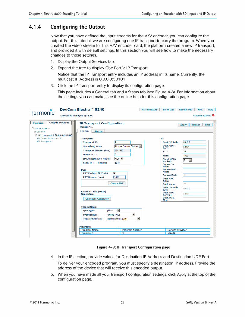
4.1.4 Configuring the OutputNow that you have defined the input streams for the A/V encoder, you can configure the output. For this tutorial, we are configuring one IP transport to carry the program. When you created the video stream for this A/V encoder card, the platform created a new IP transport, and provided it with default settings. In this section you will see how to make the necessary changes to those settings.
1. Display the Output Services tab.
2. Expand the tree to display Gbe Port > IP Transport.
Notice that the IP Transport entry includes an IP address in its name. Currently, the multicast IP Address is 0.0.0.0:50101
3. Click the IP Transport entry to display its configuration page.
This page includes a General tab and a Status tab (see Figure 4-8). For information about the settings you can make, see the online help for this configuration page.
Figure 4-8: IP Transport Configuration page
4. In the IP section, provide values for Destination IP Address and Destination UDP Port.
To deliver your encoded program, you must specify a destination IP address. Provide the address of the device that will receive this encoded output.
5. When you have made all your transport configuration settings, click Apply at the top of the configuration page.

Chapter 4 Electra 8000 Encoding Tutorial Configuring an Encoder with SDI Input and IP Output
© 2011 Harmonic Inc. 24 SAG, Version 5, Rev A
6. In the Output Services tab, expand the IP Transport entry and click Program 1 to display its configuration page (Figure 4-9).
This page includes a General tab and a Descriptors tab (see Figure 4-9). For information about the settings you can make, see the online help for this configuration page.
On the General tab, assign a descriptive name to the program.
Figure 4-9: Program Configuration page
7. When you have made your program configuration settings, click Apply at the top of the configuration page.
8. Finally, you should rebuild the PSI data for the encoder. At the top of the SAG screen, click Rebuild PSI.
4.1.5 SummaryIn this tutorial you saw how to create encoding streams for the SDI input to an A/V encoder card. The tutorial showed minimal configuration for a primary video stream and an audio stream. It then showed you how to specify the destination address for an IP transport.
To encode a video program for real-world delivery, you will have to configure many other settings for your streams, programs, and transports. For example, you should add other data streams to your program such as ancillary data (VBI/VANC), DPI, etc. To learn more about these other settings, please consult the online help for your encoding platform.

Chapter 4 Electra 8000 Encoding Tutorial Configuring a FLEX-based Encoder with IP Input
© 2011 Harmonic Inc. 25 SAG, Version 5, Rev A
4.2 Configuring a FLEX-based Encoder with IP InputIn this tutorial you will see how to configure:
■ IP input of an encoded program
■ Decoding of the input program data, with audio passthrough
■ Encoding of the decoded data streams
■ Output over an IP transport
This tutorial assumes the encoder platform has at least one FLEX decoder module and one A/V encoder card. It also assumes no configuration specified for any streams. Figure 4-10 shows the SAG screen for a platform that has no configuration settings.
Figure 4-10: FLEX Encoder Platform with No Configuration
Note that the Platform tab shows entries for each card mounted on the machine, but those entries do not contain any streams. In this figure you see entries for:
■ A Gbe-Input card
■ Two FLEX decoder modules, with two ports each
■ Four A/V encoder cards
■ One ASI-Output card (not discussed in this tutorial)
Also notice that there are no alarms present when the platform is in this state.

Chapter 4 Electra 8000 Encoding Tutorial Configuring a FLEX-based Encoder with IP Input
© 2011 Harmonic Inc. 26 SAG, Version 5, Rev A
4.2.1 Discovering Programs on the IP InputThe first step is to establish an input transport for the encoder platform and discover the programs that it carries. The discovered data will be the input to the FLEX decoder.
1. Begin by displaying SAG in your browser. (See 2.1.2 Displaying SAG on page 11 for instructions.)
The platform displays a SAG page similar to Figure 4-10.
2. In the Platform tab, click the entry for the Gbe-Input card.
The input card’s configuration page appears. The configuration page in Figure 4-11 is for a Gbe-Input card.
Figure 4-11: Gbe-Input Configuration Page
3. Click Add new Transport.
SAG creates a transport entry in the Transport Settings table. This new transport has default values for the input IP address and port. You must specify an IP address that is valid for the incoming data.
4. In the Platform tab, expand the Gbe-Input entry and click on the entry for the new transport to display its configuration page (Figure 4-12).

Chapter 4 Electra 8000 Encoding Tutorial Configuring a FLEX-based Encoder with IP Input
© 2011 Harmonic Inc. 27 SAG, Version 5, Rev A
Figure 4-12: Input Transport Configuration Page
5. Specify a valid input IP address.
In the Input Transport Settings section, specify the following:
❑ Multicast IP Address—Provide the IP address for a multicast group that is carried on the transport.
❑ Port No—Specify the port number for that multicast group.
6. When you have made your settings, click Apply at the top of the configuration page.
7. Display the Discovered Info tab (Figure 4-13).
Figure 4-13: Input Transport Discovered Info Tab
8. Click Do Input Discovery.

Chapter 4 Electra 8000 Encoding Tutorial Configuring a FLEX-based Encoder with IP Input
© 2011 Harmonic Inc. 28 SAG, Version 5, Rev A
The encoder platform performs discovery for this transport and lists the programs and streams that it finds.
Figure 4-14: Input Transport Detected Programs and Streams
4.2.2 Assigning Discovered Streams to a Decoder PortWhen you have discovered streams on the input, you can then assign it to a FLEX decoder. Each decoder has two output SDI ports, and you assign one program to each port. Each output port is wired to the input of a specific A/V encoder card.
When you assign a video stream to a FLEX port, the encoder platform creates a complete data flow, from the decoder, through the encoder, and out through an IP transport. In this tutorial we will assign the input to the first FLEX decoder, on port 1.
1. Write down the PID values for the discovered streams.
2. In the Platform tab, click on the first Decoder entry to display its configuration page.
Figure 4-15: Decoder Configuration Page

Chapter 4 Electra 8000 Encoding Tutorial Configuring a FLEX-based Encoder with IP Input
© 2011 Harmonic Inc. 29 SAG, Version 5, Rev A
3. Assign the main input video stream to an SDI port on this decoder module.
The first stream you make for a decoder port is the main video stream. To create this stream, you specify:
❑ Decoder Port—When you choose a port, SAG populates the Encoding Slot/Port popup list. Remember that the decoder ports are wired to specific encoder cards, so these two fields must correspond. For this tutorial, we will set the program to port 1.
❑ Stream Type—You can create an HD or an SD stream. For this tutorial, we will select Main Video HD.
❑ Encoding Slot/Port—For the current release of SAG, there is only one choice for the decoder port you have chosen.
❑ Input Transport—Choose the input transport that you created in 4.2.1 Discovering Programs on the IP Input on page 26.
When you have made your settings, click Create Stream.
The encoding platform creates the decode video stream in the decoder’s Card Streams table. It also creates a video stream on the encoder that you specified in the Encoding Slot/Port setting (Figure 4-16).
Figure 4-16: Video Stream on the Decoder Configuration Page
4. Configure the decoder video stream.
After you create the video stream, you must specify the input PID to match the value that you wrote down for the discovered video stream. See Figure 4-14 on page 28 for an example of discovered input streams. The table shows the PIDs for these streams.
In the Platform tab, expand the Decoder > SDI Port 1 entry, and click on the Video 1 (Decode) entry to display that stream’s configuration page (Figure 4-17).

Chapter 4 Electra 8000 Encoding Tutorial Configuring a FLEX-based Encoder with IP Input
© 2011 Harmonic Inc. 30 SAG, Version 5, Rev A
Figure 4-17: Video Decoding Configuration Page
❑ In the Stream Settings section, specify Input PID. Use the value that you wrote down for the discovered video stream. For the example in this tutorial, the value is 34.
❑ In the Stream Settings section, provide a descriptive name for the video stream.
❑ In the Video Settings section, specify the settings for the decoded video. For information about the specific settings, see the online help for this configuration page. You will have to remember these settings later when you configure the video stream on your target A/V encoder card.
For this tutorial, specify the following:
Output Video Standard: 1080i/25
Compression Codec: MPEG-2
Aspect Ratio: 16:9
Vertical Resolution: Standard
HD Format Mismatch Mode: Disable Format Switch
HD to SD Downconvert Mode: Letterbox
Decode Freeze Output Mode: Black Frame
When you have made your settings, click Apply at the top of the configuration page.
5. Assign a passthrough audio stream to the decoder.
In the Platform tab, click the entry for the decoder to display its configuration page. Make the following settings:
❑ Decoder Port—1
❑ Stream Type—Passthrough Audio Stream
❑ Input Transport—Choose the transport you created for this tutorial
When you have made your settings, click Create Stream.

Chapter 4 Electra 8000 Encoding Tutorial Configuring a FLEX-based Encoder with IP Input
© 2011 Harmonic Inc. 31 SAG, Version 5, Rev A
6. Configure the audio passthrough stream.
After you create the audio stream, you must specify the input PID to match the value that you wrote down for the discovered audio stream. See Figure 4-14 on page 28 for an example of discovered input streams. The table shows the PIDs for these streams.
In the Platform tab, expand the Decoder > SDI Port 1 entry, and click on the Audio 1-1 (Passthrough) entry to display that stream’s configuration page (Figure 4-18).
Figure 4-18: Audio Passthrough Configuration Page
❑ In the Stream Settings section, specify Input PID. Use the value that you wrote down for the discovered audio stream. Also specify the Output PID. For the example in this tutorial, the value is 33 for both fields, but you can specify a different PID for the output.
❑ In the Stream Settings section, provide a descriptive name for the video stream.
❑ In the Audio Passthrough Settings section, specify the settings for the audio stream. The sample rate must match the input for passthrough. For information about the specific settings, see the online help for this configuration page.
When you have made your settings, click Apply at the top of the configuration page.

Chapter 4 Electra 8000 Encoding Tutorial Configuring a FLEX-based Encoder with IP Input
© 2011 Harmonic Inc. 32 SAG, Version 5, Rev A
4.2.3 Reviewing the Decoder InputAt this point we have specified an input IP transport, discovered the program streams on that transport, and assigned video and audio passthrough to a port on a FLEX encoder. If you expand the tree items in the Platform tab, and select the entry for the FLEX port you have encoded, the SAG screen should be similar to Figure 4-19.
Figure 4-19: Configured Input Streams
Notice the following points on the Platform tab:
■ Gbe-Input
The Gbe-Input card shows a single transport, which has, a valid multicast IP address. The decoder input streams come from this multicast group. We executed discovery on that transport, and found six streams. The entries for these streams are in Program 1. Each entry shows the stream’s PID. The system finds the PID values as a part of discovery, and you will need these PID values as you assign streams to the decoder port.
■ Decoder and SDI Port
Each decoder has two SDI output ports. For this tutorial, we have assigned streams to Port 1. On the encoder platform, these ports are wired to the inputs of specific A/V encoder cards. When you choose the decoder port to configure, you also choose which encoder card will process the decoded data.
In this tutorial we configured the video stream to be decoded (Video 1), and assigned an audio stream for passthrough.
■ Audio/Video Encoder 1
If you look at the expanded entry for this A/V encoder, you see that the encoder platform has created a video stream on that card. By configuring the FLEX port, you have determined the input to this decoder. As a result, the platform can create the corresponding data streams on the encoder. The platform also creates a default output transport for this encoder’s program.

Chapter 4 Electra 8000 Encoding Tutorial Configuring a FLEX-based Encoder with IP Input
© 2011 Harmonic Inc. 33 SAG, Version 5, Rev A
In the Output Services tab, you can see that the encoder has created a program and a transport to carry that program as IP output (Figure 4-20).
Figure 4-20: Default Program and Transport
In the following sections you will see how to configure the re-encoding and output of this program.
4.2.4 Configuring the Encoder StreamsTo configure the video stream on the encoder:
1. In the Program tab, click the encoder you want to configure.
SAG displays the A/V encoder configuration page, which should be similar to Figure 4-21. Note that the Audio Passthrough stream is not in this Card Streams table, it is in the Decoder (FLEX) slot 4 Card Streams table.
Figure 4-21: A/V Configuration Page

Chapter 4 Electra 8000 Encoding Tutorial Configuring a FLEX-based Encoder with IP Input
© 2011 Harmonic Inc. 34 SAG, Version 5, Rev A
2. Configure the video stream.
In the Card Streams table, click Video 1 to display the configuration page for that stream (Figure 4-22). This page includes four tabs of settings you can make for this video stream. For this tutorial, we will only look at the General tab.
SAG provided default values for the settings on this page, and you can leave many of them as they are. However, you must change other settings to make them match the settings you made for the decoder video stream.
For this tutorial, we make the following changes:
❑ Stream section
Stream Name: Provide a descriptive name for the stream (Tutorial Video 1)
❑ Video Format section
Input Format: 1080i/25
Aspect Ratio: 16:9
❑ Encoding section
Compression Codec: MPEG-2
For the other settings on this page, we can use the default values.
When you have made all your stream configuration settings, click Apply.
Figure 4-22: Configuration Page for the Encoder Main Video Stream
The audio passthrough stream has been configured in the Decoder (FLEX) section (see Figure 4-18).

Chapter 4 Electra 8000 Encoding Tutorial Configuring a FLEX-based Encoder with IP Input
© 2011 Harmonic Inc. 35 SAG, Version 5, Rev A
4.2.5 Configuring the OutputWe now have a video stream configured on the encoder, and an audio passthrough stream. The next step is to configure the output. For this tutorial, we are configuring one IP transport to carry the video and audio streams in a program.
When you created your streams on the FLEX decoder, the encoding platform created a program and IP transport (see Figure 4-20 on page 33.), and provided it with default settings. In this section you will see how to make the necessary changes to those settings.
1. Display the Output Services tab.
2. Expand the tree to display Gbe Port > IP Transport 1.
Notice that the IP Transport entry includes an IP address in its name. Currently, the IP Address is 0.0.0.0:50101.
3. Click the IP Transport entry to display its configuration page.
This page includes a General tab and a Status tab (Figure 4-23). For information about the settings you can make, see the online help for this configuration page.
Figure 4-23: IP Transport Configuration page
4. In the IP section, provide values for Dest IP Addr and Dest UDP Port.
To deliver your encoded program, you must specify a destination IP address. Provide the address of the device that will receive this encoded output.
5. When you have made all your transport configuration settings, click Apply at the top of the configuration page.

Chapter 4 Electra 8000 Encoding Tutorial Configuring a FLEX-based Encoder with IP Input
© 2011 Harmonic Inc. 36 SAG, Version 5, Rev A
6. In the Output Services tab, expand the IP Transport entry and click Program 1 to display its configuration page (Figure 4-24).
This page includes a General tab and a Descriptors tab. For information about the settings you can make, see the online help for this configuration page.
On the General tab, assign a descriptive name to the program.
7. When you have made your program configuration settings, click Apply at the top of the configuration page.
8. Finally, you should rebuild the PSI data for the encoder. At the top of the SAG screen, click Rebuild PSI.
Figure 4-24: Program Configuration Page
4.2.6 SummaryIn this tutorial you saw how to configure a FLEX system with IP input. You created a video stream on the decoder, which was wired to the SDI input of an A/V encoder card. For audio, you created a passthrough audio stream on the decoder. This stream is not processed by the A/V encoder.
The tutorial showed the minimal configuration for the IP input, the FLEX decoding, the re-encoding on the A/V encoder card, and output over an IP transport.
To decode and re-encode a video program for real-world delivery, you will have to configure many other settings for your streams, programs, and transports. To learn more about these other settings, please consult the online help for your encoding platform.

© 2011 Harmonic Inc. 37 SAG, Version 5, Rev A
Chapter 5Electra 5000, 5400, 7000, and Ion Tutorial
Even if you use a template configuration to get started, you must step through the configuration, from input into the encoder platform, through decoding (if the platform includes FLEX modules), encoding, assembly into a program, and output via a transport. This chapter describes the minimal configuration to achieve end-to-end processing of a program, from encoder input, to output via a transport, on the Electra 5000, Electra 5400, Electra 7000, Ion, Ion AVC-S and Ion AVC-H encoders.
5.1 Configuring an Encoder with SDI Input and IP OutputIn this tutorial you will see how to configure encoding for a program from the SDI input to a single A/V encoder card. You will see how to create and configure:
■ An HD video stream—the steps for setting up SD encoding are identical, only with SD-specific parameters
■ An audio stream
■ An IP transport to carry the output
This tutorial assumes an encoder with at least one A/V encoder card, and support for HD encoding. It also assumes the encoder platform has no configuration specified for any streams. This tutorial will not cover encoding audio via a separate audio adapter card. Figure 5-1 shows SAG for a platform that has no configuration settings.
Figure 5-1: Encoder Platform Before Stream Configuration

Chapter 5 Electra 5000, 5400, 7000, and Ion Tutorial Configuring an Encoder with SDI Input and IP Output
© 2011 Harmonic Inc. 38 SAG, Version 5, Rev A
Note that the Platform tab shows entries for each encoding card mounted on this example machine, but those entries do not contain any streams. In this figure you see entries for:
■ Four A/V encoder cards
■ One audio adapter card (not discussed in this tutorial).
■ One ASI-Output card (not discussed in this tutorial)
Also notice that there are no alarms present when the platform is in this state.
5.1.1 Creating a Video StreamThe first step is to configure the main video stream for the program you want to encode.
1. Begin by displaying SAG in your browser. (See 2.1.2 Displaying SAG on page 11 for instructions.)
The platform displays a SAG page similar to Figure 5-1.
2. In the Platform tab, click the entry for the A/V encoder you want to configure.
The encoder card’s configuration page appears. The configuration page in Figure 5-2 is for an A/V encoder that supports HD AVC encoding.
Figure 5-2: A/V Encoder Configuration Page
3. Specify Stream Type.
The first stream you create for an A/V encoder is the main video stream.
4. Specify the Program for this stream.
When you create the main video stream for an encoder, you also specify its program. This stream will be identified in a PMT along with the other streams that are part of the same program.
Because we started with an unconfigured encoder platform, there are no programs to choose from. For this step we choose Create New Program.
5. Specify the Transport for this stream.
When you create the main video stream for an encoder, you also specify the output transport that will carry it. The transport will include a PAT entry for the stream’s program.
Because we started with an unconfigured encoder platform, you must create a new transport. Encoder platforms can support IP and ASI output. Be sure to choose Create New IP Transport.

Chapter 5 Electra 5000, 5400, 7000, and Ion Tutorial Configuring an Encoder with SDI Input and IP Output
© 2011 Harmonic Inc. 39 SAG, Version 5, Rev A
6. Create the new stream.
When you have made the stream type, program, and transport settings, click Create Stream. The encoder platform creates the new stream, program, and transport. These each have default values.
Figure 5-3: A New Main Video Stream
Notice that the Platform tab in SAG now shows the entries for the new objects (Figure 5-3). The Card Streams table also shows the new main video stream and its program. You can navigate to the program, stream and transport to specify their configurations.
7. Configure the video stream.
In the Card Streams table, click Video 1 to display the configuration page for that stream (Figure 5-4).

Chapter 5 Electra 5000, 5400, 7000, and Ion Tutorial Configuring an Encoder with SDI Input and IP Output
© 2011 Harmonic Inc. 40 SAG, Version 5, Rev A
Figure 5-4: Configuration Page for the New Main Video Stream
This page includes four tabs of settings you can make for this video stream. For this document, we will only look at the General tab. The values on this tab are set by default. To process the incoming video, you might need to change some of these settings.
The most important settings to consider are in the Input section. These settings must match the actual video input carried on the SDI port to this A/V card. For specific information about these fields, see the help for this configuration page.
Harmonic also recommends that you provide descriptive names for your streams and programs. By default, the encoder named your stream Video 1. You can provide a descriptive name on this page. For this tutorial, we’ll name it Tutorial Video 1.
When you have made all your stream configuration settings, click Apply.
5.1.2 Adding an Audio Stream to the ProgramNow that you have a main video stream and a program, you can add an audio stream to the program.
1. In the Platform tab, click the A/V encoder you are configuring.
2. In the Create New Stream section, choose Audio Stream from the Stream Type popup list. The SAG screen should be similar to Figure 5-5.

Chapter 5 Electra 5000, 5400, 7000, and Ion Tutorial Configuring an Encoder with SDI Input and IP Output
© 2011 Harmonic Inc. 41 SAG, Version 5, Rev A
Figure 5-5: Creating an Audio Stream
3. Click Create Stream.
The encoder creates the new audio stream. SAG adds the audio stream to the Card Streams table, and displays it as an entry in the Platform tab to the left.
4. In the Card Streams table, click the new audio stream to open its configuration page(Figure 5-6).
Figure 5-6: Configuring an Audio Stream
This page includes two tabs of settings you can make for the audio stream. For this document, we will only look at the General tab. The values on this tab are set by default. To process the incoming audio, you might need to change some of these settings.
The most important settings to consider are in the Format section. Select the desired output Coding, Sample Rate, Mode and ES Bit Rate.
Note that the Input Type of this audio is Embedded. This is because the audio stream is

Chapter 5 Electra 5000, 5400, 7000, and Ion Tutorial Configuring an Encoder with SDI Input and IP Output
© 2011 Harmonic Inc. 42 SAG, Version 5, Rev A
included in the SDI input to the A/V encoder card. For specific information about the audio configuration fields, see the help for this configuration page.
Harmonic also recommends that you provide descriptive names for your streams and programs.
When you have made all your stream configuration settings, click Apply.
5.1.3 Reviewing the Video and Audio StreamsAt this point we have the input for a program specified, and the preliminary configuration for the program’s streams. If you display the A/V encoder’s configuration page, the SAG screen should be similar to Figure 5-7. Notice the following points:
■ Platform Tab
❑ The Control Board entry shows links to PSI configuration for the current transports and programs specified for the encoder. Note that you can make configuration settings that will change the PSA data for your system. In that case, you still see an alarm for stale PSI data. To clear that alarm, click Rebuild PSI at the top of the GUI screen.
❑ The A/V Encoder entry shows the streams that are currently defined for that encoder card. You can click these items to display their configuration pages.
■ A/V Encoder Configuration page
The Card Streams table shows each stream currently defined for this card. You can delete a stream by clicking its red X. You cannot delete the main video stream until you have deleted all subordinate streams. You can click entries in this table to display the corresponding configuration pages.
You can create new streams to add other data to the program. For example, on this encoder you can create Low Resolution Video, VANC, DPI, and Audio streams.
■ Alarms
At the top-right of the GUI screen you can see an LED for active alarms. As you add streams to the program, the GUI will report alarms. To see the current list of alarms, click the Active Alarms link. To resolve these alarms, you configure the streams, programs, and transports for this platform. When your configuration is complete, you should see no alarms and the LED should be green.
Figure 5-7: Two Streams on an Encoder

Chapter 5 Electra 5000, 5400, 7000, and Ion Tutorial Configuring an Encoder with SDI Input and IP Output
© 2011 Harmonic Inc. 43 SAG, Version 5, Rev A
5.1.4 Configuring the OutputNow that you have defined the input streams for the A/V encoder, you can configure the output. For this tutorial, we are configuring one IP transport to carry the program. When you created the main video stream for this A/V encoder card, the platform created a new IP transport, and provided it with default settings. In this section you will see how to make the necessary changes to those settings.
1. Display the Output Services tab.
2. Expand the tree to display Gbe Port > IP Transport.
Notice that the IP Transport entry includes an IP address in its name. Currently, the multicast IP Address is 0.0.0.0:50101
3. Click the IP Transport entry to display its configuration page.
This page includes a General tab and a Status tab (see Figure 5-8). For information about the settings you can make, see the help for this configuration page.
Figure 5-8: IP Transport Configuration page
4. In the IP section, provide values for Destination IP Address and Destination UDP Port.
To deliver your encoded program, you must specify a destination IP address. Provide the address of the device that will receive this encoded output.
5. When you have made all your transport configuration settings, click Apply at the top of the configuration page.

Chapter 5 Electra 5000, 5400, 7000, and Ion Tutorial Configuring an Encoder with SDI Input and IP Output
© 2011 Harmonic Inc. 44 SAG, Version 5, Rev A
6. In the Output Services tab, expand the IP Transport entry and click Program 1 to display its configuration page (see Figure 5-9).
This page includes a General tab and a Descriptors tab. For information about the settings you can make, see the help for this configuration page.
On the General tab, assign a descriptive name to the program.
Figure 5-9: Program Configuration page
7. When you have made your program configuration settings, click Apply at the top of the configuration page.
8. Finally, you should rebuild the PSI data for the encoder. At the top of SAG screen, click Rebuild PSI.
5.1.5 SummaryIn this tutorial you saw how to create encoding streams for the SDI input to an A/V encoder card. The tutorial showed minimal configuration for a main video stream and an audio stream. It then showed you how to specify the destination address for an IP transport.
To encode a video program for real-world delivery, you will have to configure many other settings for your streams, programs, and transports. For example, you should add other data streams to your program such as VBI, VANC, DPI, etc. To learn more about these other settings, please consult the online help for your encoding platform.

Chapter 5 Electra 5000, 5400, 7000, and Ion Tutorial Configuring a FLEX-based Encoder with IP Input
© 2011 Harmonic Inc. 45 SAG, Version 5, Rev A
5.2 Configuring a FLEX-based Encoder with IP InputIn this tutorial you will see how to configure:
■ IP input of an encoded program
■ Decoding of the input program data, with audio passthrough
■ Encoding of the decoded data streams
■ Output over an IP transport
This tutorial assumes the encoder platform has at least one FLEX decoder module and one A/V encoder card. It also assumes no configuration specified for any streams. Figure 5-10 shows the SAG screen for a platform that has no configuration settings.
Figure 5-10: FLEX Encoder Platform with No Configuration
Note that the Platform tab shows entries for each card mounted on the machine, but those entries do not contain any streams. In this figure you see entries for:
■ A Gbe-Input card
■ Two FLEX decoder modules, with two ports each
■ Four A/V encoder cards
■ One ASI-Output card (not discussed in this tutorial)
■ One audio adapter card (not discussed in this tutorial).
Also notice that there are no alarms present when the platform is in this state.

Chapter 5 Electra 5000, 5400, 7000, and Ion Tutorial Configuring a FLEX-based Encoder with IP Input
© 2011 Harmonic Inc. 46 SAG, Version 5, Rev A
5.2.1 Discovering Programs on the IP InputThe first step is to establish an input transport for the encoder platform and discover the programs that it carries. The discovered data will be the input to the FLEX decoder.
1. Begin by displaying SAG in your browser. (See 2.1.2 Displaying SAG on page 11 for instructions.)
The platform displays a SAG page similar to Figure 5-10.
2. In the Platform tab, click the entry for the Gbe-Input card.
The input card’s configuration page appears. The configuration page in Figure 5-11 is for a Gbe-Input card.
Figure 5-11: Gbe-Input Configuration Page
3. Click Add new Transport.
SAG creates a transport entry in the Transport Settings table. This new transport has default values for the input IP address and port. You must specify an IP address that is valid for the incoming data.
4. In the Platform tab, expand the Gbe-Input entry and click on the new transport entry to display its configuration page.(Figure 5-12)

Chapter 5 Electra 5000, 5400, 7000, and Ion Tutorial Configuring a FLEX-based Encoder with IP Input
© 2011 Harmonic Inc. 47 SAG, Version 5, Rev A
Figure 5-12: Input Transport Configuration Page
5. Specify a valid input IP address.
In the Input Transport Settings section, specify the following:
❑ Multicast IP Address—Provide the IP address for a multicast group that is carried on the transport.
❑ Port No—Specify the port number for that multicast group.
6. When you have made your settings, click Apply at the top of the configuration page.
7. Display the Discovered Info tab.(Figure 5-13)
Figure 5-13: Input Transport Discovered Info Tab

Chapter 5 Electra 5000, 5400, 7000, and Ion Tutorial Configuring a FLEX-based Encoder with IP Input
© 2011 Harmonic Inc. 48 SAG, Version 5, Rev A
8. Click Do Input Discovery
The encoder platform performs discovery for this transport and lists the programs and streams that it finds. In this example, it displays eight programs, each with various streams. For this tutorial, we will configure decoding and re-encoding for Program 1, so we will make note of the PIDs for the streams in Program 1.
Figure 5-14: Input Transport Detected Programs and Streams

Chapter 5 Electra 5000, 5400, 7000, and Ion Tutorial Configuring a FLEX-based Encoder with IP Input
© 2011 Harmonic Inc. 49 SAG, Version 5, Rev A
5.2.2 Assigning Discovered Streams to a Decoder PortWhen you have discovered streams on the input, you can then assign it to a FLEX decoder. Each decoder has two output SDI ports, and you assign one program to each port. Each output port is wired to the input of a specific A/V encoder card.
When you assign a video stream to a FLEX port, the encoder platform creates a complete data flow, from the decoder, through the encoder, and out through an IP transport. In this tutorial we will assign the input to the first FLEX decoder, on port 1.
1. Write down the PID values for the discovered streams.
2. In the Platform tab, click on the first Decoder entry to display its configuration page.
Figure 5-15: Decoder Configuration Page
3. Assign the main input video stream to an SDI port on this decoder module.
The first stream you make for a decoder port is the main video stream. To create this stream, you specify:
❑ Decoder Port—When you choose a port, SAG populates the Encoding Slot/Port popup list. Remember that the decoder ports are wired to specific encoder cards, so these two fields must correspond. For this tutorial, we will set the program to port 1.
❑ Stream Type—Because this is the first stream on this decoder port, Video Stream is the only available option.
❑ Encoding Slot/Port—For the current release of SAG, there is only one choice for the decoder port you have chosen.
❑ Input Transport—Choose the input transport that you created in 5.2.1 Discovering Programs on the IP Input on page 46.
When you have made your settings, click Create Stream.

Chapter 5 Electra 5000, 5400, 7000, and Ion Tutorial Configuring a FLEX-based Encoder with IP Input
© 2011 Harmonic Inc. 50 SAG, Version 5, Rev A
The encoding platform creates the decode video stream in the decoder’s Card Streams table. It also creates a video stream on the encoder that you specified in the Encoding Slot/Port setting.
Figure 5-16: Video Stream on the Decoder Configuration Page
4. Configure the decoder video stream.
After you create the video stream, you must specify the input PID to match the value that you wrote down for the discovered video stream. See Figure 5-14 on page 48 for an example of discovered input streams. This table shows the PIDs for these streams.
In the Platform tab, expand the Decoder > SDI Port 1 entry, and click on the Video 1 (Decode) entry to display that stream’s configuration page (Figure 5-17).

Chapter 5 Electra 5000, 5400, 7000, and Ion Tutorial Configuring a FLEX-based Encoder with IP Input
© 2011 Harmonic Inc. 51 SAG, Version 5, Rev A
Figure 5-17: Video Decoding Configuration Page
❑ In the Stream Settings section, specify Input PID. Use the value that you wrote down for the discovered video stream. For the example in this tutorial, the value is 611.
❑ In the Stream Settings section, provide a descriptive name for the video stream.
❑ In the Video Settings section, specify the settings for the decoded video. For information about the specific settings, see the help for this configuration page. You will have to remember these settings later when you configure the video stream on your target A/V encoder card.
For this tutorial, specify the following:
Output Video Standard: 1080i/25
Compression Codec: MPEG-2 or H.264
Aspect Ratio: 16:9
Vertical Resolution: Standard
HD Format Mismatch Mode: Disable Format Switch
HD to SD Downconvert Mode: Letterbox
Decode Freeze Output Mode: Black Frame
When you have made your settings, click Apply at the top of the configuration page.
5. Assign a passthrough audio stream to the decoder.
In the Platform tab, click the entry for the decoder to display its configuration page (Figure 5-16). Make the following settings:
❑ Decoder Port—1
❑ Stream Type—Passthrough Audio Stream
❑ Input Transport—Choose the transport you create for this tutorial
When you have made your settings, click Create Stream.

Chapter 5 Electra 5000, 5400, 7000, and Ion Tutorial Configuring a FLEX-based Encoder with IP Input
© 2011 Harmonic Inc. 52 SAG, Version 5, Rev A
6. Configure the audio passthrough stream.
After you create the audio stream, you must specify the input PID to match the value that you wrote down for the discovered audio stream. See Figure 5-14 on page 48 for an example of discovered input streams. This table shows the PIDs for these streams.
In the Platform tab, expand the Decoder > SDI Port 1 entry, and click on the Audio 1-1-1 (Passthrough) entry to display that stream’s configuration page.
Figure 5-18: Audio Passthrough Configuration Page
❑ In the Stream Settings section, specify Input PID. Use the value that you wrote down for the discovered audio stream. Also specify the Output PID. For the example in this tutorial, the value is 36 for both fields, but you can specify a different PID for the output.
❑ In the Stream Settings section, provide a descriptive name for the video stream.
❑ In the Audio Passthrough Settings section, specify the settings for the audio stream. The sample rate must match the input for passthrough. For information about the specific settings, see the help for this configuration page.
When you have made your settings, click Apply at the top of the configuration page.
5.2.3 Reviewing the Decoder InputAt this point we have specified an input IP transport, discovered the program streams on that transport, and assigned video and audio passthrough to a port on a FLEX encoder. If you expand the tree items in the Platform tab, and select the entry for the FLEX port you have encoded, the SAG screen should be similar to Figure 5-19.

Chapter 5 Electra 5000, 5400, 7000, and Ion Tutorial Configuring a FLEX-based Encoder with IP Input
© 2011 Harmonic Inc. 53 SAG, Version 5, Rev A
Figure 5-19: Configured Input Streams
Notice the following points on the Platform tab:
■ Gbe-Input
The Gbe-Input card shows a single transport, which has a valid multicast IP address. The decoder input streams come from this multicast group. We executed discovery on that transport, and found streams for eight different programs. Each entry shows the stream’s PID. The system finds the PID values as a part of discovery, and you will need these PID values as you assign streams to the decoder port. For this tutorial, we used the streams in Program 1.
■ Decoder and SDI Port
Each decoder has two SDI output ports. For this tutorial, we have assigned streams to Port 1. On the encoder platform, these ports are wired to the inputs of specific A/V encoder cards. When you choose the decoder port to configure, you also choose which encoder card will process the decoded data.
In this tutorial we configured the video stream to be decoded (Tutorial Video 1), and assigned an audio stream for passthrough.
■ Audio/Video Encoder 1
If you look at the expanded entry for this A/V encoder, you see that the encoder platform has created a video stream on that card. By configuring the FLEX port, you have determined the input to this decoder. As a result, the platform can create the corresponding data streams on the encoder. The platform also creates a default output transport for this encoder’s program.

Chapter 5 Electra 5000, 5400, 7000, and Ion Tutorial Configuring a FLEX-based Encoder with IP Input
© 2011 Harmonic Inc. 54 SAG, Version 5, Rev A
In the Output Services tab, you can see that the encoder platform has created a program and a transport to carry that program as IP output.
Figure 5-20: Default Program and Transport
In the following sections you will see how to configure the re-encoding and output of this program.
5.2.4 Configuring the Encoder StreamsTo configure the video stream on the encoder:
1. In the Program tab, click the encoder you want to configure. For this tutorial, we choose the first A/V card, which takes input from port 1 on the FLEX module.
SAG displays the A/V encoder configuration page, which should be similar to Figure 5-21. Note that the Audio Passthrough stream is not in this Card Streams table, it is in the Decoder (FLEX) slot 4 Card Streams table.
Figure 5-21: A/V Configuration Page

Chapter 5 Electra 5000, 5400, 7000, and Ion Tutorial Configuring a FLEX-based Encoder with IP Input
© 2011 Harmonic Inc. 55 SAG, Version 5, Rev A
2. Configure the video stream.
In the Card Streams table, click Video 1 to display the configuration page for that stream (Figure 5-22). This page includes four tabs of settings you can make for this video stream. For this tutorial, we will only look at the General tab.
SAG provided default values for the settings on this page, and you can leave many of them as they are. However, you must change other settings to make them match the settings you made for the decoder video stream.
For this tutorial, we use the following settings:
❑ Stream section
Stream Name: Provide a descriptive name for the stream (Tutorial Video 1)
❑ Input section
Standard: 1080i
Frame Rate: 25
Aspect Ratio: 16:9
❑ Encoding section
Compression Codec: H.264
For the other settings on this page, we can use the default values.
When you have made all your stream configuration settings, click Apply.
Figure 5-22: Configuration Page for the Encoder Video Stream
The audio passthrough stream has been configured in the Decoder (FLEX) section (see Figure 5-18).

Chapter 5 Electra 5000, 5400, 7000, and Ion Tutorial Configuring a FLEX-based Encoder with IP Input
© 2011 Harmonic Inc. 56 SAG, Version 5, Rev A
5.2.5 Configuring the OutputWe now have a video stream configured on the encoder, and an audio passthrough stream. The next step is to configure the output. For this tutorial, we are configuring one IP transport to carry the video and audio streams in a program.
When you created your streams on the FLEX decoder, the encoding platform created a program and IP transport (see Figure 5-20 on page 54.), and provided it with default settings. In this section you will see how to make the necessary changes to those settings.
1. Display the Output Services tab.
2. Expand the tree to display Gbe Port > IP Transport 1.
Notice that the IP Transport entry includes an IP address in its name. Currently, the IP Address is 0.0.0.0:50101
3. Click the IP Transport entry to display its configuration page.
This page includes a General tab and a Status tab (Figure 5-23). For information about the settings you can make, see the help for this configuration page.
Figure 5-23: IP Transport Configuration page
4. In the IP section, provide values for Dest IP Addr and Dest UDP Port.
To deliver your encoded program, you must specify a destination IP address. Provide the address of the device that will receive this encoded output.
5. When you have made all your transport configuration settings, click Apply at the top of the configuration page.

Chapter 5 Electra 5000, 5400, 7000, and Ion Tutorial Configuring a FLEX-based Encoder with IP Input
© 2011 Harmonic Inc. 57 SAG, Version 5, Rev A
6. In the Output Services tab, expand the IP Transport entry and click Program 1 to display its configuration page.
This page includes a General tab and a Descriptors tab (see Figure 5-24). For information about the settings you can make, see the help for this configuration page.
On the General tab, assign a descriptive name to the program.
7. When you have made your program configuration settings, click Apply at the top of the configuration page.
8. Finally, you should rebuild the PSI data for the encoder. At the top of the SAG screen, click Rebuild PSI.
Figure 5-24: Program Configuration Page
5.2.6 SummaryIn this tutorial you saw how to configure a FLEX system with IP input. You created a video stream on the decoder, which was wired to the SDI input of an A/V encoder card. For audio, we created a passthrough audio stream on the decoder. This stream is not processed by the A/V encoder.
The tutorial showed the minimal configuration for the IP input, the FLEX decoding, the re-encoding on the A/V encoder card, and output over an IP transport.
To decode and re-encode a video program for real-world delivery, you will have to configure many other settings for your streams, programs, and transports. To learn more about these other settings, please consult the online help for your encoding platform.

Harmonic Inc.4300 North First StreetSan Jose, CA 95134, U.S.A.T +1 408 542 2500 F +1 408 490 6708
www.harmonicinc.com
© Copyright 2011 Harmonic Inc. All rights reserved. Manual Part No. MAN-SAEGS-005