elasticity theory for self-assembled protein lattices with
TRANSCRIPT
Elasticity theory for self-assembled protein lattices with application to the martensitic phasetransition in bacteriophage T4 tail sheath
Wayne Falk*Department of Diagnostic and Biological Sciences, University of Minnesota, Minneapolis, Minnesota 55455, USA
Richard D. James†
Department of Aerospace Engineering and Mechanics, University of Minnesota, Minneapolis, Minnesota 55455, USA�Received 17 August 2005; revised manuscript received 23 November 2005; published 27 January 2006�
We propose an elasticity theory for one- and two-dimensional arrays of globular proteins for which the freeenergy is affected by relative position and relative rotation between neighboring molecules. The kinematics ofsuch assemblies is described, the conditions of compatibility are found, a form of the free energy is given, andformulas for applied forces and moments are developed. It is shown that fully relaxed states of sheets consistof helically deformed sheets which themselves are composed of helical chains of molecules in rational direc-tions. We apply the theory to the fascinating contractile deformation that occurs in the tail sheath of the virusbacteriophage T4, which aids its invasion of its bacterial host. Using electron density maps of extended andcontracted sheaths, we approximate the domains of each molecule by ellipsoids and then evaluate our formulasfor the position and orientation of each molecule. We show that, with the resulting kinematic description, theconfigurations of extended and contracted tail sheaths are generated by a simple formula. We proposed aconstrained version of the theory based on measurements on extended and contracted sheath. Following asuggestion of Pauling �Discuss. Faraday Soc. 13, 170 �1953��, we develop a simple model of the molecularinteraction. The resulting free energy is found to have a double-well structure. Certain simple deformations arestudied �tension, torsion inflation�; the theory predicts a first-order Poynting effect and some unexpectedrelations among moduli. Finally, the force of penetration is given, and a possibly interesting program ofepitaxial growth and patterning of such sheets is suggested.
DOI: 10.1103/PhysRevE.73.011917 PACS number�s�: 87.10.�e
I. INTRODUCTION
A remarkably large number of biological structures arecomposed of identical protein molecules, or mixtures of afew different protein molecules, in regular arrays. Examplesare microtubules, bacterial flagella, F-actin filaments, and vi-ral coats. These are different from typical inorganic crystalsin that the individual molecules are composed of many atomsand the whole array is typically not a three-dimensional �3D�crystal but is often a single-molecule-thick regular array on asheet, either flat, curved, or polyhedral, or else in a linearchain. Often the latter adopt helical forms, and, in the ex-ample below of the bacteriophage T4 tail sheath, the cylin-drical sheath is composed of two families of helical chains ofproteins. Besides the reduced dimensionality and natural cur-vature, the protein-protein interactions involve one or morebonding sites with groups of bonded atoms distributed overthe bonding site. Because of this, the interactions can becomplex �from a first principles’ viewpoint� and proteins ex-ert both forces and moments on each other. However, a sim-plifying feature of the interactions is that individual proteinmolecules in such arrays predominantly interact only withnearest neighbors.
With the rapid development of optical tweezers andatomic force microscopes �1,2�, it has become possible to
subject a protein structure to a force or moment and to mea-sure its elastic response. These experiments seem to be ofteninterpreted in terms of classical macroscopic theories of elas-ticity. For example, Kirchhoff’s rod theory is often used tointerpret experiments on chains such as DNA �3–5�. As dis-cussed by these authors, Kirchhoff’s rod theory is expectedto be valid when the length of the chain is much larger thanits diameter and helical pitch, and it has been used success-fully in such cases. But Kirchhoff’s rod theory is built oncertain assumptions relating to the macroscopic theory ofnonlinear elasticity. Thus, for example, in its simplest aniso-tropic form, three suitable bending-torsion experiments suf-fice to determine the moduli, meaning that the mechanicalbehavior in all subsequent experiments is then determined. Inaddition, with only a few molecules �138 in the case of theT4 tail sheath� or with localized large curvatures, a molecularelasticity theory may be needed.
For these reasons we develop here an elasticity theory thatis suitable for these protein arrays. The proteins themselveshave irregular yet well-defined shapes and they interact vialocalized bonding sites. We steer a course midway betweendetailed first principles calculations on the given protein se-quence �which, at present, would leave us stuck on the pro-tein folding problem� and macroscopic nonlinear elasticity.First, each molecule is given a position and orientation. Weexplain how position and orientation are related to detailedstructure, in a manner that is consistent with the results offirst principles calculations. Our definition is different fromthe usual one, but seems to have some advantages. It also has
*Electronic address: [email protected]†Electronic address: [email protected]
PHYSICAL REVIEW E 73, 011917 �2006�
1539-3755/2006/73�1�/011917�23�/$23.00 ©2006 The American Physical Society011917-1

the property that the position and orientation are given by atranslation and rigid rotation of a reference molecule thatbest approximates, in a least squares sense, the deformedmolecule. As for interactions, we focus on pairwise forcesand moments, because bonding between globular proteins isoften localized at the region of contact between two proteins.Because we have an orientation variable as well as a posi-tional one, our theory also has points of contact with thetheory of liquid crystals, but in the end the theory is quitedifferent.
We propose a form of the free energy based on these ideas�Sec. III�. Imposing the condition of frame indifference, wedefine certain “strain variables” upon which the free energydepends. Conditions of compatibility concern the extent towhich these strain variables can be assigned independently:for sheets, we find that necessary and sufficient conditionsfor compatibility �of a simply connected sheet, defined pre-cisely below� are that a certain pair of sums of four termsvanishes. These relate to the process of checking compatibil-ity around elementary squares consisting of four molecules.We find these conditions to be very useful.
For both chains and sheets, helical configurations arise asthe natural ordered structures. In particular, under generalconditions they are the free energy minimizers in the absenceof boundary conditions. These results can be considered asanalytical expressions of the ideas of Crane �8�. Ultimatelythe reason is the same reason that these configurations arenatural in nonlinear elasticity �Ericksen �9��. To oversimplify,in a helical configuration any two parts of the chain, of equalmonomer length, are related by a Euclidean transformation.Therefore, the equilibrium of a short section implies, viarotation and translation, that the whole helix is in equilib-rium. In the present context they play a deeper role: fullyrelaxed states of a sheet governed by our free energy consistof helically deformed sheets which themselves are composedof helical chains of molecules �Sec. VIII�.
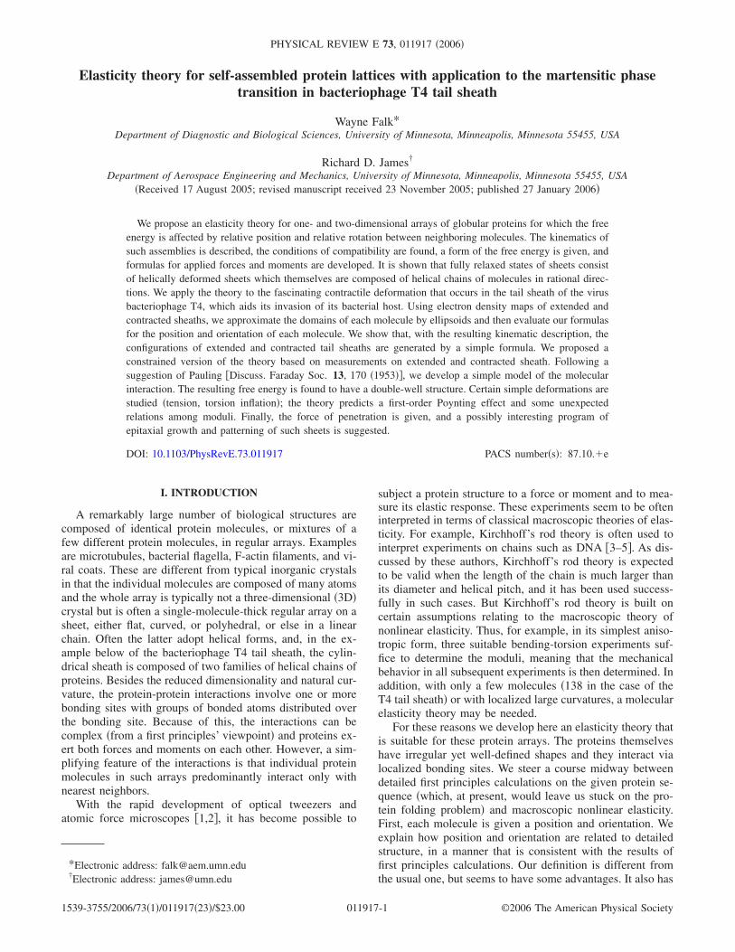
Using this theory, we study of deformations of the tailsheath of bacteriophage T4 �Fig. 1�. Bacteriophages are vi-ruses that attack bacteria. The T4 virus is composed of acapsid containing the viral DNA �Fig. 1�a�� and a tail shownextending down from the capsid. The tail consists of a pair ofconcentric cylinders �Fig. 1�b�� each about 1000 Šlong. The
inner tail tube with a diameter of about 90 Å is surroundedby the tail sheath with an outer diameter of about 240 Å. Thesheath is composed of six parallel helices, made from chainsof a single type of protein. Although the tail sheath is a singlemolecular layer protein sheet, it should not be considered �asis assumed by nonlinear plate theory� thin relative to itsradius of curvature, this ratio being �thickness� / �meanradius of curvature��1.
Prior to invasion of the host, the sheath proteins are ar-ranged as steeply pitched helices, and the tail adopts so-called extended structure. During the virus’ attack on a bac-terium, the tail sheath changes shape dramatically; theprotein helices compress, causing the sheath to shorten andfatten into a more compact contracted structure. This drivesthe relatively rigid inner tail tube through the cell wall, mak-ing a passage for the viral DNA to pass into the host �Fig.1�c��. During this process the sheath contracts irreversibly toabout 1 /3 of its original length accompanied by a 50% in-crease in outer diameter. The transformation has many fea-tures in common with martensitic phase transformations, ashas been noted by Olson and Hartman �7�. For a generalreview of T4 tail structure and function see Rossmann et al.�10�.
Once the viral DNA is inside the host, it reprograms thehost cell to produce all ingredients needed to form new vi-ruses. The viral protein molecules produced by this processself-assemble into virus progeny within the host, eventuallycausing it to burst, releasing the viruses to infect other hosts.
We apply the theory of the protein sheet to the tail sheathof bacteriophage T4. Using measured electron density mapsof extended and contracted sheath �11,12�, we identify threedomains in each molecule and approximate these by ellip-soids. We then define the structures of the two phases. Wedevelop a simple formula that produces these structures �Eq.�40��, and applies to any any model of the molecule, how-ever complex. The simplicity of this formula arises from thefact that, even though the molecule itself may be complex,the relationship between different molecules is very simple.Based on the experimentally observed mode of deformation,we adopt a constrained theory for the sheath. The constraintsare exactly satisfied by both extended and contracted sheath.The resulting theory has surprising implications with regardto the response of the sheath to different loadings, includinga strong first order Poynting effect, unexpected relations be-tween moduli, certain combinations of applied axial forceand moment that do no work on the sheath, and a certainrelation between the force and moment needed to transformcontracted to extended sheath. Among these results, there arenumerous possible points of comparison with future small-scale quantitative experiments.
A very early model of helical contraction proposed byPauling �13� provides a basis for simplifying our free energy.Pauling envisioned that helices forming a cylinder could becompressed to the point where adjacent turns of the helixwould form bonds. This leads to a simple model of interac-tions with one family of bonds guiding assembly and anothercausing contraction. As higher resolution images of the T4tail sheath become available �11�, this remains likely theprincipal mechanism for sheath contraction. Guided by Paul-ing’s mechanism, we build a simplified free energy for theT4 tail sheath.
FIG. 1. �Color online� �a� Structure of bacteriophage T4, basedon electron microscope structure analysis to a resolution of about2–3 nm, from �6�. Reproduced with permission of Fred Eiserling.�b� A cross section showing concentric tail tube and sheath annuli.�c� Schematic of contraction process �7�.
W. FALK AND R. D. JAMES PHYSICAL REVIEW E 73, 011917 �2006�
011917-2
The deformation of the T4 tail sheath is a particularlyinteresting case for the theory for several reasons: �1� verylarge changes of shape in an organized protein structure takeplace as a means of producing force, �2� the shape changehas been identified as of martensitic type, which suggests amultiwell elasticity theory, and �3� there is an interest inunderstanding how this phase transformation relates to non-biological martensitic transformations, and in particular howthe force and energy of contraction compare in the biologicaland nonbiological cases. The latter could suggest strategiesfor manmade analogs of the T4 tail sheath. Finally, �4� aquantitative evaluation of the energy stored has interestingbiological significance. That is, in bacteriophage T4, as in allviruses, there is no mechanism for the production of energy.Thus, all the energy that is released upon contraction of thetail sheath must be stored during the assembly phase of thevirus, from apparently high free energy molecules createdduring translation of the viral genome, aided by the energyconsuming translation mechanism of the bacterial host. Forthe purpose of storage of this energy, the process of epitaxialstabilization, familiar from the growth of semiconductorcompounds on single crystal substrates, apparently plays animportant role. Motivated by these ideas we suggest such aprogram of epitaxy �Sec. X�.
Mathematical notation. Boldfaced uppercase letters are3�3 matrices and boldfaced lowercase letters are vectors inR3. Components are relative to a fixed orthonormal basisthroughout. Lowercase greek letters denote components ofvectors while lowercase latin letters are indices for mol-ecules, e.g., the �i , j�th molecule of a sheet. Z2 denotes allpairs of integers �i , j�. The summation convention is used;A ·B is the inner product between matrices, A ·B=A��B��,and �A�=�ATA. The superscript T denotes transpose, trA=A�� is the trace of A, I is the identity matrix, �a � b� is thematrix with components a�b�, SkewA= �1/2��A−AT�, and3�3 rotation matrices are denoted by SO�3�= �R :RTR=I ,detR= +1.
II. KINEMATIC DESCRIPTION OF INDIVIDUALPROTEIN MOLECULES, CHAINS, AND SHEETS
We are interested in chains and sheets consisting of pro-tein molecules. For simplicity we shall consider both struc-tures to consist of identical molecules.1
A molecule will be specified by a pair �y ,R� consisting ofa position vector y�R3 and a rotation matrix R�SO�3�,termed, respectively, position and orientation. Protein chainsand sheets are constructed by building up one- and two-dimensional arrays of these molecules. For chains we choosea set of integers �1, . . . ,N corresponding to N molecules andassign mappings
y:�1, . . . ,N → R3, R:�1, . . . ,N → SO�3� . �1�
For sheets we denote molecules by pairs of integers �i , j��Z2. We consider a set D= �1, . . . ,N� �1, . . . ,M and map-pings
y:D → R3, R:D → SO�3� . �2�
For the configuration of a single molecule we use the obvi-ous notation �yi ,Ri� for chains and �yi,j ,Ri,j� for sheets.More generally, D could have the form ��Z2 where � is adomain in the plane.
The usual way to define orientation of a molecule, or acollection of molecules, is to take moments of the �time av-eraged� mass distribution �see, e.g., de Gennes �14�, Chap.2�, typically the second or fourth moment. Below, we suggesta different definition of orientation that seems to have advan-tages with regard to the connection with molecular dynamicssimulation.
Each molecule consists of � atoms of C, H, and variousother elements in a folded configuration. For each atom weassign a corresponding atomic mass mi , i=1, . . . ,�. Nearphysiological temperatures, the atoms in a protein moleculeundergo rather large vibrations, but it is still sensible to talkabout the time averaged position on macroscopic time scalesand we shall assign these average positions as y1 , . . . ,y�.Time averaged momentum has dynamical significance, so weuse it to define the position of a molecule. We will take itsposition to be its mass averaged position,
y =
i=1
�
miyi
i=1
�
mi
. �3�
From the same information we can also obtain a measure ofthe orientation of a molecule. That is, we consider a mol-ecule in standard position defined by fixed atomic positionsx1 , . . . ,x�. This standard position could for example be thecollection of positions in a crystallized form of the molecule,deduced from x-ray crystallography, or from theoretical stud-ies of the configuration of single molecules in solution. Fromthese reference positions we define the mass averaged refer-ence position as above,
x =
i=1
�
mixi
i=1
�
mi
. �4�
A natural concept of orientation is obtained through the av-erage deformation gradient of the molecule, defined in thefollowing way:
F =
i=1
�
mi�yi − y� � �xi − x�
r2i=1
�
mi
. �5�
Here, r can be taken as a typical radius of the referencemolecule, e.g.,
1The extension to regular arrays of several different proteins isexpected to be similar.
ELASTICITY THEORY FOR SELF-ASSEMBLED … PHYSICAL REVIEW E 73, 011917 �2006�
011917-3
r =� mi�xi − x�2
mi
. �6�
�The position and orientation of a molecule will turn out tobe independent of r.� The expression �5� for F is dimension-less and translation invariant. Typically, it will be true thatdet F�0, which we assume. If the yi represent a rigid defor-mation of the reference molecule, i.e., yi=Qxi+c, i= �1, . . . ,�, Q�SO�3�, then it follows from Eq. �5� that
F = QV , �7�
where
V =
i=1
�
mi�xi − x� � �xi − x�
r2i=1
�
mi
. �8�
The latter is interpretable as a normalized reference momentof inertia. In general we will use the rotation in the polardecomposition of F as a measure of orientation. That is, wewill write
F = RU where R � SO�3� and U = UT is positive definite,
�9�
and define R in this decomposition as the orientation. Formolecules that deform as well as rotate and translate, R isstill a natural measure of orientation.
These definitions of position and orientation, the latterdefined by a polar decomposition of the apparently compli-cated formula for F, have several attractive features. First,we observe that both F and y are linear functions of thepositions y1 , . . . ,y�. We have framed the definitions in thisway so that their second time derivatives are immediatelyrelated to �time averaged� forces via the equations of mo-lecular dynamics. Second, there is a useful variational char-acterization of R and y. That is, R�xi−x�+y is the rigiddeformation that best approximates the mass distribution ofthe molecule in the least squares sense. More precisely, if weconsider the rotation matrix Q and vector c that minimize2
minc,Q�SO�3�
� �y�z� − ��Q�z − x� + c���2dm�z� , �10�
where dm is the mass measure of the molecule, i.e., m=mi�xi
, and y�xi�=yi, then it follows from the simple qua-dratic minimization problem �10� that Q=R and c=y as de-fined by Eqs. �3�, �5�, and �9�. The proof of this fact isstraightforward. First, by differentiating Eq. �10� with respectto c we conclude immediately that c=y. Then we replace c=y in Eq. �10� and simplify. The minimization over Q�SO�3� then becomes
minQ�SO�3�
�− tr�QTF�� = − maxQ�SO�3�
tr�QTF�
= − maxQ�SO�3�
tr�QTRU� = − maxQ�SO�3�
tr�QU�
= − maxQ�SO�3�
�
�e� · Qe�, �11�
where �e1 ,e2 ,e3 are orthonormal eigenvectors of U withcorresponding positive eigenvalues �1 ,2 ,3. It is immedi-ately seen that the latter maximization problem is uniquely
solved by Q=I, implying that Q=R.The orientation R can be obtained from the formula R
=FU−1=F��FTF�−1, the square root being the uniquepositive-definite square root. For the purpose of a con-strained molecular dynamic simulation �with given R� it isuseful to have a linear constraint. A necessary3 condition thatR is related to F by Eq. �9� is that Skew�RFT�=0, that is,
Skew R�i=1
�
mi�xi − x� � �yi − y��� = 0, �12�
which is a linear constraint on the yi.In summary, our basic kinematics of a molecule is speci-
fied by a pair �y ,R� defined by Eqs. �3�, �5�, �8�, and �9�. Wewish to emphasize again that this choice of kinematics doesnot entail assumptions of rigidity of molecules. These formu-las do allow one to determine our kinematic variables fromunrestricted first principles calculations. We note that thereare more complicated theories possible with this general typeof kinematics. A further possible generalization would bethat the free energy is affected by position and and full de-formation gradient of molecules defined by �5�.
III. FREE ENERGY
Although all atoms have infinite range, each protein mol-ecule interacts primarily with its close neighbors and weshall develop the theory on this basis. Because bonding sitesare often localized and interlocking, molecules are expectedto exert both forces and moments on neighboring molecules.
We base the theory on a formula for the free energy. Wemake two simplifying assumptions which easily could begeneralized: �1� the molecules are identical �thus we can usethe reference configuration introduced in Sec. II for all mol-ecules�, and �2� we consider only nearest neighbor interac-tions. For chains, the “nearest neighbor” of i� �2, . . . ,N−1 refers to the two molecules i−1, i+1 for interior mol-ecules while it refers to the molecule 2 for i=1 and N−1 fori=N. For sheets there are various possibilities. One can havetriangular lattices with each molecule bonded to six nearestneighbors or rectangular lattices with each molecule having
2We write this as an integral rather than a sum to indicate that thischaracterization of R and y applies to any mass distribution.
3This condition is nearly sufficient for the determination of R, the
only freedom being that if R satisfies Eq. �12� then so does RR
where R is a 180° rotation about one of the eigenvectors of U. Inpractice, if the configuration is changing slowly, this nonuniquenesswould not cause a problem.
W. FALK AND R. D. JAMES PHYSICAL REVIEW E 73, 011917 �2006�
011917-4
four nearest neighbors or more complicated situations. In thecase of four nearest neighbors the nearest neighbors of �i , j�consist of all molecules of the form �i+1, j� , �i−1, j� , �i , j+1� , �i , j−1� that lie in D. If not all four of these are in D wecall �i , j� a boundary molecule; otherwise, we call it an inte-rior molecule. Here we write the free energy only in the caseof four nearest neighbors, the generalizations being auto-matic.
Since such protein arrays are of interest in solution, theassumptions are somewhat different than would be appropri-ate for atoms in a polymeric chain or a crystal. In particularthe “free energy” will be taken as the free energy of theprotein assembly and a fixed volume V of the surroundingsolution. This is appropriate to the case that V is surroundedby a large bath B having fixed temperature and fixed chemi-cal potentials of species in solution. All free energies belowwill depend on the temperature and chemical potentials, butsince these will be fixed throughout this paper, we will leavethese parameters out of the notation. As is well known thepresence of the solution profoundly affects the free energy ofthe protein through osmotic effects, but it also affects theform of the free energy. In particular, boundary moleculesmay have a free energy that is different from interior mol-ecules, because one or more of their bonding sites is un-bonded and exposed directly to the solution.
In this simplest situation we will assume that, for chains,there is a molecular interaction free energy which dependson the position and orientation of a pair of molecules�a ,R ,b ,Q� defined for a ,b�R3 and R ,Q�SO�3�. In or-der to accommodate the possibility of boundary effects, wedistinguish the free energy contribution from the interactionof the first and second molecules, 1�a ,R ,b ,Q� and the nextto last and last ones, N�a ,R ,b ,Q�. The total free energy isthen
��y1,R1, . . . ,yN,RN� = i=2
N−2
�yi,Ri,yi+1,Ri+1�
+ 1�y1,R1,y2,R2�
+ N�yN−1,RN−1,yN,RN� . �13�
The main physical assumption embodied here is that the con-tribution to the free energy from a pair of molecules is unaf-fected by the positions and orientations of all other mol-ecules in the chain, in keeping with the idea that the mainfree energy changes are due to changes in conformation atthe bonding site between a pair of molecules.
For sheets the assumptions are analogous. In this casethere are 15 different kinds of boundary molecules, depend-ing on which of the four bonds is missing. To simplify thenotation we let B be the set of boundary molecules and writethe total free energy as
��y1,1,R1,1, . . . ,yN,M,RN,M�
= �i,j��Z2�D\B
1�yi,j,Ri,j,yi+1,j,Ri+1,j�
+ 2�yi,j,Ri,j,yi,j+1,Ri,j+1� + �i,j��B
i,jB , �14�
where i,jB is a free energy for the boundary molecules. Each
i,jB is one of the 15 functions describing the free energy of
interaction of boundary molecules with dependence on theposition and orientation of neighbors that are present. Inwriting this free energy, we have effectively assumed that allbonding sites of between molecules i , j and i , j+1 are thesame, independent of i and j, and the same for sites of theform i , j and i+1, j. Also, in many interesting cases not all ofthe 15 kinds of boundary molecules are represented. For ex-ample, in an isolated T4 tail sheath as usually pictured, thereare only two kinds of boundary molecules.
The condition of frame indifference restricts the form ofthe molecular free energies. We note first that, according tothe definitions �3� and �9�, the quantities y1 and R1 are trans-formed into Ry1+c and RR1 under a superimposed rigidbody motion Ryi+c of all the atoms. Thus, in the case ofchains, the condition of frame indifference is �for interiormolecules�
�y1,R1,y2,R2� = �Ry1 + c,RR1,Ry2 + c,RR2� , �15�
which must hold independently for R ,R1 ,R2�SO�3�, andc ,y1 ,y2�R3. Making the special choice R=R1
T and c=−R1
Ty1, we see that
�y1,R1,y2,R2� = „0,I,R1T�y2 − y1�,R1
TR2… = ��t,Q� ,
�16�
where Q=R1TR2 is a relative orientation that is unaffected by
rigid body rotations and t=R1T�y2−y1� is a relative transla-
tion which is also unaffected by superimposed rigid motions.Note that Q is not simply the rotation which maps the orien-tation of molecule 2 into that of molecule 1 �or vice versa�,and similarly, t is not a simple translation of 2 into 1. Rather,these quantities behave like strains, and describe the six de-grees of freedom associated with the straining of bond sitescaused by changes of orientation and relative position of 1and 2.
For sheets the restrictions of frame indifference are simi-lar: the functions 1 and 2 in �14� both satisfy �16�. We let�1,2 be the corresponding reduced functions defined by �16�subscripted by 1,2.
IV. COMPATIBILITY
Compatibility concerns the extent to which one can pre-scribe the quantities describing strain, or, more generally, thefunctions on which the free energy depends after the condi-tion of frame indifference has been imposed. In our case thisconcerns the extent to which we can assign the relative trans-lations and relative orientations.
In the case of chains we therefore assign�t1 ,Q1 , . . . , tN−1 ,QN−1� and ask whether there are positionsand orientations �y1 ,R1 , . . . ,yN ,RN� consistent with these inthe sense that ti=Ri
T�yi+1−yi� and Qi=RiTRi+1, i=1, . . . ,N
−1. It is immediately seen that these conditions are solvable,and all solutions are related to each other by exact rigidmotions of the entire molecule. Hence, the problem of com-patibility for chains is analogous to the case of 1D rod theo-ries in continuum mechanics: there are no conditions of com-
ELASTICITY THEORY FOR SELF-ASSEMBLED … PHYSICAL REVIEW E 73, 011917 �2006�
011917-5

patibility and the freedom is precisely overall rigiddeformations.
For sheets there are nontrivial restrictions of compatibil-ity, as expected based on continuum shell theories. We beginby considering the case of four bonding directions. For theanalysis below a path is a succession of nearest neighbors inD and a loop is a closed path. We assume here that D isdiscretely simply connected in the sense that every point isconnected to every other point by a path and any non-self-intersecting closed loop in D�Z2 is the boundary of theunion of �closed� unit squares contained in D. We assignrelative translations and relative orientations
�ti,j,Qi,j�, �i, j� � Dr, and �ti,j,Qi,j�, �i, j� � Du,
�17�
where Dr,u are the subsets �i , j��D such that �i+1, j� ��i , j+1�� are also in D �r denotes “right” and u denotes “up”�.We ask whether there are positions and orientationsyi,j ,Ri,j , �i , j��D, that satisfy
ti,j = Ri,jT �yi+1,j − yi,j� ,
Qi,j = Ri,jT Ri+1,j, �i, j� � Dr,
ti,j = Ri,jT �yi,j+1 − yi,j� ,
Qi,j = Ri,jT Ri,j+1, �i, j� � Du. �18�
Immediately we see that there are some restrictions. For ex-ample, if Ri,j has been determined, then by successive appli-cation of �18�2,4 there are overdetermined equations for, say,Ri+1,j+1, these being
Ri+1,j+1 = Ri,j+1Qi,j+1 = Ri,jQi,jQi,j+1,
Ri+1,j+1 = Ri+1,jQi+1,j = Ri,jQi,jQi+1,j . �19�
Equating these, we get
Qi,jQi,j+1 = Qi,jQi+1,j , �20�
or
Qi,jQi,j+1Qi+1,jT Qi,j
T = I . �21�
This has the following interpretation: as we go, say, clock-wise around a unit square in the lattice Z2, the product of theQ’s �taken with transpose if the path goes to the left ordown� is the identity. Two neighboring squares, both tra-versed clockwise, give such identities of the form
Q1Q2Q3TQ1
T=I and Q3Q4Q5TQ3
T=I which immediately gives
I=Q1TQ1Q2Q3
TQ3Q4Q5TQ3
T=Q1TQ1Q2Q4Q5
TQ3T, that is,
Q1Q2Q4Q5TQ3
TQ1T=I; this is a similar compatibility condition
for the rectangle consisting of the union of the two squares.
By induction and using the discrete simple connectedness4 ofD, this extends to any non-self-intersecting closed loop inD�Z2.
So far, the argument concerns the solution of the last twoequations of �18�. For the translations, by again traversing aunit square in the clockwise sense, we have from �18�1,3 thatRi,jti,j +Ri,j+1ti,j+1−Ri+1,jti+1,j −Ri,jti,j =0, which, after pre-multiplication by Ri,j
T gives
ti,j + Qi,jti,j+1 − Qi,jti+1,j − ti,j = 0 . �22�
As above, equations of this form for neighboring squares canbe combined to an equation of compatibility for a rectangleand then, by iteration, to a non-self-intersecting closed loop.
By this time it is clear that the pattern of argument isessentially the same as that for differentials �i.e., this kind ofargument does not really use that the differentials are small,if only nearest neighbors interactions are considered�. Thatis, necessary and sufficient conditions for �17� to be compat-ible are that the compatibility conditions for unit squares inD, i.e., all equations of the form
Qi,jQi,j+1Qi+1,jT Qi,j
T = I ,
ti,j + Qi,jti,j+1 − Qi,jti+1,j − ti,j = 0 �23�
are satisfied. The necessity of these conditions has beenproved above. The sufficiency follows by giving arbitrarilyy0,0�R3 ,R0,0�SO�3�, assuming without loss of generalitythat �0,0� is in D. Then, for any other �k ,m��DB, we con-sider a path from �0,0� to �k ,m�. Successive application ofEq. �18� determines first Rk,m and then yk,m, and every suchR ,y along this path. By a process of exhaustion, i.e., con-struct a path which does not cross itself or any other path toa point whose values R ,y have not been determined from apreviously determined one, we then determine all valuesRi,j ,yi,j. These satisfy all of the equations �18�. That is, byconstruction, a point �i , j� and neighbor �i+1, j� ��i , j+1��are each connected to �0,0� by a path used in the construc-tion. These paths may coincide over some initial length, but,once they depart from each other, they never intersect. Thus,by possibly shortening the loop, we can without loss of gen-erality assume the paths form a non-self-intersecting loopwith a single link removed. Satisfaction of �18� then holds asa consequence of the compatibility condition for such loops.
There is clearly also uniqueness of the construction ofRi,j ,yi,j up to the choice of R0,0 ,y0,0, which, by the frameindifference of the quantities Q , t is equivalent to uniquenessup to overall rigid deformation.
Suppose now we add additional bonding directions. Sincethe equations �23� are both necessary and sufficient for theexistence of the positions and orientations, and these posi-tions and orientations are uniquely determined up to overalltranslation and rotation �which does not affect the �t ,Q�’s�,
4By the discrete simple connectedness of D, a non-self-intersecting loop in D�Z2 encloses a union of squares that can becompletely exhausted by adding successive squares that share anedge.
W. FALK AND R. D. JAMES PHYSICAL REVIEW E 73, 011917 �2006�
011917-6

then all values of �t ,Q� corresponding to other bonding di-
rections are uniquely determined by �ti,j ,Qi,j� , �ti,j ,Qi,j�. Onecan write formulas for these. For example, if �as in the T4sheath� we have the additional bonding directions �i , j�− �i−1, j+1�, then
ti,j =def
Ri,jT �yi−1,j+1 − yi,j� = Qi−1,j
T �ti−1,j − ti−1,j� ,
Qi,j =def
Ri,jT Ri−1,j+1 = Qi−1,j
T Qi−1,j . �24�
In summary, with additional bonding directions, necessaryand sufficient conditions for compatibility are �23�, togetherwith the formulas of the type �24� that uniquely determinethe values of �t ,Q� for these additional directions in terms of
�ti,j ,Qi,j� , �ti,j ,Qi,j�.
V. HELICAL CONFIGURATIONS
As shown in Fig. 4 below, the tail sheath of bacteriophageT4 is a sheet consisting of the union of two families of he-lices. Helical structures arise often in biology and they alsohave special position within the context of the present theory,as we explain in this and the following sections.
From a purely geometric viewpoint Crane in 1950 �8�argued that if two proteins have complementary bondingsites and molecules bond at a specific angle, then chains ofthese molecules are likely to from helices. In nonlinear elas-ticity of rods and plates, helical configurations also arise in anatural way �Ericksen �9�, Chouaieb and Maddocks �4�, andMoakher and Maddocks �5��. In all of these arguments theframe-indifference of the free energy plays a central role,allowing the variables describing strain to be either constant�in rod theory� or else to depend on fewer reference coordi-nates for these special configurations.
We begin with chains and recall from �16� that the mo-lecular free energy depends on relative translation and orien-tation �t ,Q�. Motivated by the examples just cited we firsttry to figure out what are all configurations�y1 ,R1 , . . . ,yN ,RN� having constant values of �t ,Q�. In thefollowing section we explain the energetic significance ofthis choice, beyond the obvious fact that such configurationshave the property that the molecular free energy is indepen-dent of the molecule. This problem is immediately solved bythe considerations of compatibility of the preceding section;we have to solve
RiT�yi+1 − yi� = t, Ri
TRi+1 = Q, i = 1, . . . ,N − 1,
�25�
and the general solution is
Ri+1 = R1Qi, yi+1 = y1 + R1j=0
i−1
Q jt, i = 1, . . . ,N − 1,
�26�
where y1�R3 ,R1�SO�3� are arbitrary, and they are alsothe values of position and orientation corresponding to mol-ecule 1. It is clear from �26� that the choice y1�R3 ,R1
�SO�3� also corresponds to an arbitrary superimposed rigiddeformation of the whole array.
The positions of the molecules described by the equations�26� lie on a helix. To see this put R1=I and note that Q=I corresponds to the degenerate case of a molecules spacedequally along a line all with the same orientation. So weassume henceforth that Q�I. Then Q has an axial vector,that is, a vector e�R3 whose direction is uniquely deter-mined such that Qe=e. By suitable choice of the magnitudeof e, we can decompose t= t� + t�, t� ·e=0, t� �e; then thesecond of �26� becomes
yi+1 = y1 + it� + j=0
i−1
Q jt�. �27�
The last term in �27� can be further simplified. To do so, notethat Q−I is invertible on the plane perpendicular to e anddefine r by �Q−I�r= t� ,r ·e=0, so that Qr=r+ t�. Now, it-erate the latter to get the identity,
Qir = r + j=0
i−1
Q jt�. �28�
Choosing the arbitrary translation y1=r �to put the origin onthe axis of the helix� and eliminating the sum in �27� using�28� we have,
yi+1 = it� + Qir , �29�
which, accounting for the conditions r ·e=0 and Qe=e, isthe equation of a helix. The orientations Ri of these helicalconfigurations also vary in a regular way along the helix in amanner given by �26� and illustrated, for example, in Fig. 5.
The basic geometric information, like formulas for thepitch and radius of the helix in terms of the given informa-tion �t ,Q�, can be read off from the formulas given in thepreceding paragraph. In particular, if � 1 is the smallestnumber such that Q�=I, then the pitch is � � t��. The radius is��Q−I�−1t��, the inverse taken on the plane perpendicular toe. This inverse is given by �Q−I�−1= �−1/ tr�Q−I���Q−I�T.
Below, we will observe that the relaxed configurations ofextended or contracted T4 tail can be viewed as a collectionof six helices, each with 24 molecules. To evaluate the posi-tions and orientations of all these molecules from experimen-tal data, it will be useful to understand how the orientationsof the molecules on a helix can be varied independently fromthe shape of the helix. This is not immediately obvious fromthe formulas �26�, but is easy to work out. First it is cleargeometrically �and it can be shown from the formulas above�that if the shape of the helix is given, i.e., all of the yi, thenassignment of the orientation of one of the molecules on thehelix determines the orientations of all the others. Thus thereis expected to be one free rotation matrix R to define thisorientation. Given a helical configuration defined by�y1 ,R1 ,Q , t�, then all other helical configurations with thesame positions are given by
�y1,R1R,RTQR,RTt�, R � SO�3� . �30�
To use this formula, one can think of beginning with a helixof the desired shape and then choosing R�SO�3� so that
ELASTICITY THEORY FOR SELF-ASSEMBLED … PHYSICAL REVIEW E 73, 011917 �2006�
011917-7

R1R is the desired orientation of molecule 1 and all theothers then follow.
For sheets there are similar kinds of helical configura-tions, having the shape of a ribbon bent and twisted into ahelix. These are discussed below in Secs. VI and VIII.
VI. BACTERIOPHAGE T4 TAIL SHEATH
In this section we specialize the formulas given above tothe T4 tail sheath. The first task is to describe the sheath inits extended and contracted configurations and identify thepositions and orientations using experimental measurements.
The T4 tail sheath can be viewed as a protein sheet asdefined above. We can think of a cylinder oriented vertically.The lowest annulus of the cylinder is a circle of six mol-ecules. Each of these six molecules generates a right handedhelical chain consisting of 23 molecules.5 Hence, we willidentify the molecules accordingly, �yi,j ,Ri,j�, i=1, . . . ,6, j=1, . . . ,23.
We work in the usual orthonormal basis �e1 ,e2 ,e3� andwithout loss of generality we will choose the overall rotationand translation so that the axes of all the helices coincidewith e3 and the first annulus lies in the e1 ,e2 plane. The firstannulus is a circle �i.e., a degenerate helical chain�. Accord-ing the results in Sec. V, this case corresponds to the casewhere t= t0 is perpendicular to the axis of Q and a littlecalculation shows that without loss of generality �by suitablyrotating the six molecules about the e3 axis� we can assume
t0 = �− �,0,0�, Q� = �cos � − sin � 0
sin � cos � 0
0 0 1� , �31�
��0, and the fact that the six molecules are equally spacedon the helix gives Q�
6=I⇒�=� /3. Without loss of general-ity we write y1=��1/2 ,�3/2 ,0�. The radius of the circle ofpositions is �.
Emanating from each of these six molecules is a helicalchain whose first molecule has now a given position andorientation. According to results of Sec. V, we need tospecify �t ,Q� for each of these chains. In fact all of thesechains have the same �t ,Q� because suitable rigid rotationsand translations bring them into coincidence with each other:the whole configuration of the tail sheath has sixfold sym-metry. The axis of Q is again e3 so Q has the form �31�2,Q=Q�. Thus, besides the radius � of the cylinder, we need todetermine the four parameters
� and t = ��1,�2,� . �32�
For this purpose we first show that �1 ,�2 are determined by �and �. Referring to Sec. V and using that the initial point isy1=��1/2 ,�3/2 ,0�, we have from the equations t= t�
+ t� , �Q−I�r= t� ,r=y1 that �Q−I�y1= t�, from which �1 ,�2
are given by
�1 =�
2��cos � − 1� − �3 sin �� ,
�2 =�
2�sin � + �3�cos � − 1�� �33�
in terms of � and �. It remains to determine � ,, and �. Thevalues of these depend on whether we consider an extendedor contracted sheath.
A. Extended tail sheath
Extended sheath has an interesting geometric propertythat we term the 8/3 rule. The rule is that the eighth mol-ecule along one of these helices, beginning at a molecule onthe first annulus, lies directly over the third molecule awaycounterclockwise along the annulus �Fig. 2�. �The justifica-tion of this rule from measured data of Leiman et al. �11� is
5Leiman et al. demonstrate �11� that the tail sheath consists of 23annuli, rather than 24 as described in preceding papers. Accordingto this work the missing annulus can now be ascribed to the base-plate, based on its detailed protein structure.
FIG. 2. �Color online� Illustration of the 8/3 rule of an extendedsheath. Top: the first eight molecules �i=1, j=1, . . . ,8� on the mainhelix, viewed down the axis of the cylinder. Bottom: the first threemolecules �i=1,2 ,3 , j=1� on the first annulus, again viewed downthe axis. The slight touching of domains of neighboring moleculeson the bottom picture is an artifact of the ellipsoidal approximation;in reality these do not touch.
W. FALK AND R. D. JAMES PHYSICAL REVIEW E 73, 011917 �2006�
011917-8

given at the end of this section.� Specifically, in our notation,
y1,8 · e1 = y3,1 · e1, y1,8 · e2 = y3,1 · e2. �34�
This statement and the helical structure of the tail implyfull periodicity, y�i,j+7� ·e1,2=y�i+2,j� ·e1,2 whenever these aredefined. With regard to the present theory, all the good prop-erties of helical configurations discussed above �and below�would hold without this “accidental” periodicity. This sug-gests that its presence is perhaps related to something otherthan the function of the tail, possibly its self-assembly viaannulus-by-annulus epitaxial growth. In this regard, if oneomits the last annulus, then the rest of the tail is exactly 1period. In other words, without omissions, the 22nd annuluslies directly over the first annulus. It will be seen below thatthis 8 /3 rule also applies to the orientation, R�1,8�=R�3,1�.This is of course the smallest period exhibited by the tailsheath. Possibly these facts are related to the process bywhich the tail tube directs the growth of the tail sheath,which is assembled in the extended form �below, the con-tracted form will not have this or a shorter period�.
The two equations �34� give apparently two restrictionson the remaining parameters �� , ,��. Written out using Eq.�26�, these two conditions are
− j=0
6
Q�j t + t0 + Q�/3t0 � e3. �35�
In fact this condition only involves � and is equivalent to thepair of equations
2 + cos 7� − �3 sin 7� = 0, �3 cos 7� + sin 7� = 0.
�36�
These equations have simultaneous roots at �=2� /21+2�n /7 where n is an integer. The root of interest �i.e.,corresponding to a fraction of a turn in the counterclockwisesense� is �=2� /21. From the form of t it can now be seenthat 21 is the pitch of the helices.
It remains to prescribe the orientations of all the mol-ecules. As explained in the few lines preceding Eq. �30� thisis assignable independently of the positions. Since we haveput R1=I, we may give this by giving the orientation ofmolecule �1,1�, from which all the orientations of all themolecules are determined. In summary, the following infor-mation is needed from experiment for extended and con-tracted tail sheaths: �1� the orientation of molecule �1,1�
=R1,1; �2� the radius of the cylinder of centers of masses =�;�3� the pitch of the helices =21.
We obtained these from electron density maps of Leimanet al. �12� �we are grateful to Petr Leiman for the prepubli-cation data on the extended sheath, without which thepresent theory would be incomplete�. See the Appendix forhow these data were used to represent the molecules. Briefly,these data do not give atom positions, but give an excellentpicture of relatively rigid collections of atoms called do-mains. Both extended and contracted sheaths consist of threesuch domains. We assumed charge neutrality and computedcenters of mass of domains, then used the formulas �3�, �5�,and �9� to compute the position and orientation. Three issuesshould be noted. �1� With three domains F is singular withrank equal to 2; nevertheless, R is uniquely determined byEq. �9�. �2� These data were rotated about the axis of thehelix and translated into the position of molecule �1,1�. Thisgives �=73.75 Å, =40.6 Å. We chose the extended sheathto be the reference configuration so that R1,1=I. For a con-tracted sheath R1,1 is given by Eq. �39� below. �3� Note fromFig. 3 that masses of domains are not conserved. This is aconsequence of the flexibility of certain bonds, which causessome mass to be lost by the averaging procedure inherent inany 3D reconstruction. To give definite results we ignoredthis problem and used the measured masses of each domain.
B. Contracted tail sheath
For the contracted tail sheath the evaluation is completelyanalogous to the above except that the 8/3 rule is replacedby a 12/1 rule,
y1,12 · e1 = y1,1 · e1, y1,12 · e2 = y1,1 · e2. �37�
As above this leads to a pair of equations for �,
1 − cos�11�� + �3 sin�11�� = 0,
�3 − �3 cos�11�� − sin�11�� = 0, �38�
having a simultaneous first positive root at �=2� /11. Asabove, to complete the description, we need the orientationof the first molecule R1,1, the radius of the cylinder �, andthe pitch of the helices, which in this case is 11. Using theelectron density maps of Leiman et al. �11� in the same man-ner as above, we get for the contracted sheath �=116.1 Å,=16.4 Å, and
FIG. 3. �Color online� Domain coordinatesused to determine orientation R1,1. The circle de-notes the centerline of the cylindrical sheath andeach molecule is modeled by three domains. �Thethree domains to the right represents a moleculeof extended sheath.� Total mass and center ofmass of each domain are shown to the right.
ELASTICITY THEORY FOR SELF-ASSEMBLED … PHYSICAL REVIEW E 73, 011917 �2006�
011917-9

R1,1 = � 0.426 0.4388 − 0.791
− 0.4378 0.8653 0.244
0.7916 0.242 0.561� �39�
In summary, the configuration of extended or contractedtail sheath is given by the following equations:
Ri,j = Q�/3i−1Q�
j−1R1,1,
yi,j = y1 + k=0
i−2
Q�/3k t0 + Q�/3
i−1k=0
j−2
Q�kt ,
i = 1, . . . ,6, j = 1, . . . ,23, �40�
where �=2� /21 for extended and �=2� /11 for contractedtail sheaths. Here, Q� , t0 are defined by Eq. �31�, y1=��1/2 ,�3/2 ,0�, t0= �−� ,0 ,0�, t=e3+ �Q�−I�y1, and weuse the convention Q�
0 =I �also, sums of the form k=0m where
m�0 are simply put equal to zero�. Pictures of extended andcontracted tail sheath obtained from formulas �40� with thedata given above are shown in Fig. 4. The method of visu-alization is to approximate the domains of the molecules ofextended and contracted sheaths by ellipsoids, centered at thecenters of mass of the domains, as described in detail in the
Appendix. As can be seen there, this is quite an accuraterepresentation of the molecule. Then we applied the formulas�40� to this collection.6
There is a substantial screw action that occurs when thesheath fully contracts. This can be seen from Fig. 5 whichshows the corresponding main right handed helices in ex-tended and contracted sheath. If the baseplate is held fixedduring contraction, the neck experiences almost a full turn,the angle change being about 343°.
We should add that the data of Leiman et al. �11� alsoprovide a direct measure of the validity of the 8/3 and 12/1rules, which we have used above to evaluate �=2� /21=17.14° and �=2� /11=32.73°, respectively. The directmeasurement of Leiman et al. gives the very nearby values�=17.2° ,32.9°.
VII. A SIMPLE CONSTRAINED THEORYFOR BACTERIOPHAGE T4 TAIL SHEATH
A. Constraints
Our general expression for the free energy �14� of a pro-tein sheet can be quite complicated, and in our case is mademore complicated by the presence of additional bonding di-
6Note that the formulas �40� can be applied with accuracy to anymodel of the molecule, including the all-atom distribution. How-ever, it is worth noting that the striking simplicity of �40� followsthe precise definitions of position and orientation we have chosen;other kinematic descriptions may not give such simple formulas.
FIG. 4. �Color online� Pictures of extended and contracted tailsheaths based on the formula �40�, using the method of visualiza-tion described in Sec. VI B.
FIG. 5. �Color online� The main helix of the T4 tail sheath inextended and contracted forms, illustrating the screw action.
W. FALK AND R. D. JAMES PHYSICAL REVIEW E 73, 011917 �2006�
011917-10

rections, as we explain below. In this section we use theknown configurations of the sheath to make simplifying as-sumptions that allow us to arrive at a manageable form of theenergy.
First we note that each molecule in the sheath undergoes asubstantial motion. Nevertheless, there are some simplifyingfeatures of this motion. These features are remarkably closeto the ideas of Pauling �13�, who, prior to any knowledge ofthe T4 tail sheath, theorized that arrays of the helices ofCrane could contract by having adjacent turns of the helixform bonds. Later, in his study of the T4 tail sheath, Moody�15� observed that bonds on the right handed helix remainedto some extent invariant during contraction. He noticed that,on the main helix, while there is a substantial relative rota-tion of molecules, the distance between neighbors does notchange too much. This concerns7 neighboring molecules ofthe form �i , j� , �i , j+1�, shown, e.g., for i=1 in Fig. 5. Ac-cording to our Eq. �40� we have for both extended and con-tracted sheaths that this distance is �t�= �Ri,j
T �yi,j+1−yi,j��; it isof course independent of both i and j and is given by
�t�2 = 2 + 2�2�1 − cos �� . �41�
When this is evaluated for extended and contracted sheathsusing the data above we get, respectively, �t�=46.2,67.4 Å.While these are fairly close, Moody noticed that if, instead ofusing the separate radii of extended and contracted sheaths,one uses in both cases an effective radius of �=�eff
=77.6 Å, then �2+2�eff2 �1−cos ��=46.7 Å for both con-
tracted and extended sheaths. The reason for the smaller-than-average effective radius presumably relates to the rela-tive importance of the bonding of inner domains, whichappear to be in contact in electron micrograph cross sectionsof the sheath at a radius near �eff.
We remark that if we approximate cos � by 1− �1/2��2 inthe expression 2+2�eff
2 �1−cos ��, and also adjust the valueof �eff slightly to �eff=76.33 Å, then we have the followingsimple quadratic condition:
2 + �2�eff2 = �2170 Å2 for extended sheath
2170 Å2 for contracted sheath.� �42�
In view of its physical interpretation, we assume �42� repre-sents a special stiffness in the T4 tail sheath and we adopt itas a constraint for all values of and �. Below we generalizeit to distorted configurations.
The constraint �42� has an interesting consequence. Todescribe this, we first recall that according to macroscopicnonlinear elasticity, a uniformly twisted cylinder subject tozero axial force and free sides changes its diameter and alsoits length. The latter is referred to as the Poynting effect. It isgenerically a second order effect: the elongation goes as thesquare of the angle of twist of the cylinder; the elongationcan be either positive or negative and it is typically positive�lengthening� for elastomeric materials. For uniform states ofthe T4 tail sheath, that is, states given by the formula �40�subject to the constraint �42�, we have a very strong first
order Poynting effect. That is because, by �40�, the end anglemeasured from the extended configuration is 22� while theheight is 22.
Thus the theory predicts a height vs twist relation asshown in Fig. 6. This is essentially a plot of the constraint�42�. Below in Sec. VII D, we show that a simplified explicitfree energy has these uniform states as local minimizing freeenergy configurations subject to small axial torque and forcenear the extended or contracted states. We note that if theapproximation cos ��1− �1/2��2 is not made, then, on thescale of Fig. 6, the resulting graph is indistinguishable fromFig. 6. Note the dramatic Poynting effect, particularly at con-tracted sheath. It would be interesting to look at this relation-ship experimentally.
There is another simplifying feature of the deformation ofthe T4 tail sheath that concerns the orientation. For molecule�1,1� the rotation that maps extended to contracted sheath isgiven in �39�, and its axis is given by
�0.001,0.875,0.485� . �43�
The angle of rotation is close to 64.8°. Remarkably, the axisof rotation �43� is within about 1° of �0,�3/2 ,1 /2�. A pos-sible reason for this rotation and its implications becomeclear when we superimpose the rotation axis �black line� onpictures of a molecule �1,1� of an extended and contractedtail sheath �Fig. 7�. From these pictures, if one thinks of themolecules as having the shape of a kind of twisted banana,then evidently the axis of rotation passes through its axis.Thus, the rotation of molecules of tail sheath seems largelyconstrained by steric hindrance. But there is another featureof this rotation that is suggested by the two pictures on theright of Fig. 7. In these two pictures we are looking directlydown the axis of rotation. One can see that the rotation of�1,1� of about 60° is causing it to align itself approximatelywith the main helix. As above, this is consistent with the ideathat there are strong bonds linking molecules on this helixthat not only constrain lengths but also relative rotations. Infact, even though the molecules depicted at the right of Fig.7 do not touch, there are strong bonds that link the innermostdomains.
We now develop this idea quantitatively. To account forthe evidence for steric hindrance, we assume that the orien-
7The relation between Moody’s notation for bonds and ours isAB= �i , j��i , j+1�, AB�= �i , j��i−1, j+1�, AC�= �i , j��i−1, j+2�.
FIG. 6. Height of the tail sheath vs end angle �measured fromextended sheath� according to the constraint, showing a strong firstorder Poynting effect. Dots correspond to extended and contractedsheaths.
ELASTICITY THEORY FOR SELF-ASSEMBLED … PHYSICAL REVIEW E 73, 011917 �2006�
011917-11
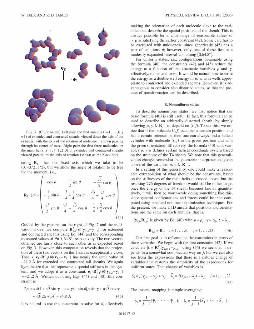
tation R1,1 has the fixed axis which we take to be�0,�3/2 ,1 /2�, but we allow the angle of rotation to be freefor the moment, i.e.,
R1,1��� =�cos �
1
2sin � −
�3
2sin �
−1
2sin �
3
4+
1
4cos �
�3
4−
�3
4cos �
�3
2sin �
�3
4−
�3
4cos �
1
4+
3
4cos �
� .
�44�
Guided by the pictures on the right of Fig. 7 and the moti-vation above, we compute R1,1
T ����y1,2−y1,1� for extendedand contracted sheaths using Eq. �44� and the correspondingmeasured values of �=0,64.8°, respectively. The two vectorsobtained are fairly close to each other as is expected basedon Fig. 7. However, this computation reveals that the projec-tion of these two vectors on the 1 axis is exceptionally close.That is, e1 ·R1,1
T ����y1,2−y1,1� has nearly the same value of−21.2 Å for extended and contracted tail sheaths. We againhypothesize that this represents a special stiffness in this sys-tem, and we adopt it as a constraint, e1 ·R1,1
T ����y1,2−y1,1�=−21.2 Å. Written out using Eqs. �44� and �40�, this con-straint is
2� cos ��1 + �3 sin � − cos �� + sin ��� sin � + ��3 cos �
− �3�2 + ��� = 84.8 Å. �45�
It is natural to use this constraint to solve for �, effectively
making the orientation of each molecule slave to the vari-ables that describe the spatial positions of the sheath. This isalways possible for a wide range of reasonable values of� ,� , satisfying the earlier constraint �42�. Some care has tobe exercised with uniqueness, since generically �45� has apair of solutions �; however, only one of these lies in amodestly expanded interval containing �0,64.8°�.
For uniform states, i.e., configurations obtainable usingthe formula �40�, the constraints �42� and �45� reduce theenergy to a function of the kinematic variables � and �,effectively, radius and twist. It would be natural now to writethe energy as a double-well energy in � ,�, with wells appro-priate to contracted and extended sheaths. However, it is ad-vantageous to consider also distorted states, so that the pro-cess of transformation can be described.
B. Nonuniform states
To describe nonuniform states, we first notice that ourbasic formula �40� is still useful. In fact, this formula can beused to describe an arbitrarily distorted sheath, by simplyallowing � ,� , ,R1,1 to depend on �i , j�. To see this, we no-tice that if the molecule �i , j� occupies a certain position andhas a certain orientation, then one can always find a helicalcylinder with molecule �i , j� in the given position and withthe given orientation. Effectively, the formula �40� with vari-ables � ,� , defines certain helical coordinate system basedon the structure of the T4 sheath. We note that this generali-zation changes somewhat the geometric interpretations givenabove of the variables � ,� , ,R1,1.
In a setting of this generality, one could make a reason-able extrapolation of what should be the constraints, basedon the stiffnesses of the main helix discussed above, but theresulting 276 degrees of freedom would still be rather large;once the energy of the T4 sheath becomes known quantita-tively, it will then be worthwhile doing something like this,since general configurations and forces could be then com-puted using standard nonlinear optimization techniques. Forthe present, we make a 1D ansatz that positions and orienta-tions are the same on each annulus, that is,
�yi,j,Ri,j� is given by Eq. �40� with � = � j, � = � j, = j ,
R1,1 = R j, i = 1, . . . ,6, j = 1, . . . ,23. �46�
Our first goal is to reformulate the constraints in terms ofthese variables. We begin with the first constraint �42�. If wecalculate �t�= �Ri,j
T �yi,j+1−yi,j�� using �46� we see that it de-pends in a somewhat complicated way on j, but we can alsosee from the expressions that there is a natural change ofvariables that restores the simplicity of the expressions foruniform states. That change of variables is
� j = j�� j+1 − � j� + � j, j = j� j+1 − j� + j, j = 1, . . . ,22.
�47�
The inverse mapping is simple averaging:
� j =1
j − 1��1 + ¯ + � j−1�, j =
1
j − 1�1 + ¯ + j−1� ,
FIG. 7. �Color online� Left pair: the first annulus �i=1, . . . ,6 , j=1� of extended and contracted sheaths viewed down the axis of thecylinder, with the axis of the rotation of molecule 1 shown passingthrough its center of mass. Right pair: the first three molecules onthe main helix �i=1, j=1,2 ,3� of extended and contracted sheathsviewed parallel to the axis of rotation �shown as the black dot�.
W. FALK AND R. D. JAMES PHYSICAL REVIEW E 73, 011917 �2006�
011917-12

j = 2, . . . ,23. �48�
Note that for uniform states, � j =� j =� and j = j =. Whenthe expression �t�2= �Ri,j
T �yi,j+1−yi,j��2 is evaluated for 1Dstates in these new variables, it becomes
� j2 − 2� j� j+1 cos � j + � j+1
2 + j2, �49�
and the connection with �41� is immediately clear. In fact, itis expected based on the definition of � j that the approxima-tion cos � j �1− �1/2�� j
2 is still reasonable and then �49� be-
comes �� j+1−� j�2+� j+1� j� j2+ j
2. Comparing with �42�, it isnatural to again replace all the � j by the effective radius �eff.We therefore adopt in the nonuniform case the constraint
j2 + � j
2�eff2 = 2170 Å2, �50�
where �eff=76.33 Å.Now we generalize the constraints �44� and �45� on the
orientation. First, we recall that our way of writing the for-mula �40� automatically adjusts the orientation of each mol-ecule on the sheath in a consistent way �preserving the heli-ces� in response to a change of R1,1. Since we assumedabove that R1,1 has the same axis for extended and con-tracted sheath, then we assume this remains true for nonuni-form states and R1,1 continues to have the form �44� with �replaced by � j.
Once again, the change of variables �47� proves to beextremely useful, for if we now calculate the quantitye1 ·Ri,j
T �yi,j+1−yi,j�=e1 ·R jT�yi,j+1−yi,j�, we get
1
4�− 2 cos � j�� j + � j+1
�3 sin � j − � j+1 cos � j�
− sin � j�� j+1 sin � j + � j+1�3 cos � j − �3�2 j + � j�� ,
�51�
with the obvious relation to �45�. We therefore adopt thefollowing constraint on orientation in the nonuniform case:
2 cos � j�� j + � j+1�3 sin � j − � j+1 cos � j� + sin � j�� j+1 sin � j
+ � j+1�3 cos � j − �3�2 j + � j�� = 84.8 Å. �52�
We again view this as a way to determine � j, j=1, . . . ,22,making the orientation slave to the other variables.
In summary, there is a natural expression of the con-straints within the context of the 1D ansatz, this being�50�–�52�; no internal contradictions arise, and there is free-dom to make a variety of distorted states that interpolatebetween contracted and extended sheaths. The unconstrainedkinematic variables can be taken to be local twist and radius,which for distorted states turn out to be �1 , . . . , �23 and�1 , . . . ,�23. If these variables are subject to a simple interpo-lation between extended and contracted sheath, by defining
� j = ��j��2�/21� + �1 − ��j���2�/11� ,
� j = ��j�73.75 Å + �1 − ��j�� 116.1 Å, �53�
where, for example, ��j� is a simple “tanh” transition layer,��s�= 1
2 �tanh��s− j0� /w�+1, then one can exhibit a contract-
ing sheath as is shown in Fig. 8. These pictures are producedin this way, using the constraints �50� and �52� to determinethe j and � j and then placing all in the formula �40�, asdirected by �46�. All three of these pictures have the sameinterfacial width w=1.5 and interfacial positions j0=4 ,12,20, respectively. These are not necessarily equilib-rium states, as the computation of these would depend on aquantitative knowledge of the energy function, which we donot yet know.
These pictures are interesting from the point of view ofnucleation. One of the important issues �raised in �16�, whererelated references can be found� is that the T4 tail sheath is ata scale that would seem to suppress the martensitic phasetransformation. Briefly, the argument is the following. In or-der to have a phase transformation with a distortion one ex-pects an interface to pass through the body having a transi-tion layer between phases. But because of the scalingbetween bulk and interfacial energy, the interfacial energyshould dominate at sufficiently small scales, and, therefore,in a sufficiently small body, one would necessarily pay morefree energy for the transition layer than the lowering of freeenergy due to the presence of the new phase. In the presentcase “interfacial” and “bulk” energies are better thought of asline and surface energies, but the argument is similar. Thus,nucleation is expected to be an important issue for phasetransitions at small scales, and this is particularly true in thepresent case in view of the enormous transformation strain ofthe T4 tail sheath. It is known from the work of Moody thattransformation begins at the baseplate. The distortion of thefirst annulus upon nucleation can be seen in Fig. 8. An alter-native view is seen in Fig. 9 which shows a view from be-low; in this figure the lowest annulus is nearly fully trans-formed �j0=4� on the left while the correspondinguntransformed sheath is shown on the right.
Finally, a brief remark about constraints and frame indif-ference. It is well known that internal constraints in mechani-cal systems should be frame indifferent, and this may not beobvious in the present case. In �40� there is some freedom ofhow one assigns a change of frame, attributing this either tochanges of � ,� , ,R1,1 or, for example, to changes of Q� �atconstant ��, Q�/3 , t0 , t ,y1 ,R1,1. The latter is preferred, and
FIG. 8. �Color online� Deformations of tail sheaths satisfyingthe constraints and exhibiting transformation. See text.
ELASTICITY THEORY FOR SELF-ASSEMBLED … PHYSICAL REVIEW E 73, 011917 �2006�
011917-13

also preserves the 1D ansatz. The precise form of a change offrame y→Ry+c, R�SO�3� is then Q�→RQ�RT, Q�/3
→RQ�/3RT, t0→Rt0,t→Rt, y1→Ry1+c, R1,1→RR1,1.With this understanding, � ,� , are objective scalars and theconstraints are frame indifferent.
C. Free energy
Having reduced the complexity of the energy by formu-lating constraints for a 1D ansatz, we are now in the positionto suggest a relatively simple form of the energy function fornonuniform states of the form �46�. We take the independentvariables to be �1 , . . . , �23 and �1 , . . . ,�23. In the extended T4tail sheath the main helix is the only direction of strongbonding; however, in the contracted sheath there are threebonding directions, as identified by Moody �15� and Leimanet al. �12�. These are the bonds �i , j�− �i , j+1�, �i , j�− �i−1, j+1�, �i , j�− �i−1, j+2�. For this bonding the free energyis a minor generalization of �14�:
��y1,1,R1,1, . . . ,y6,23,R6,23�
= i��1,. . .,6,j��1,. . .,23
1�yi,j,Ri,j,yi,j+1,Ri,j+1�
+ 2�yi,j,Ri,j,yi−1,j+1,Ri−1,j+1�
+ 3�yi,j,Ri,j,yi−1,j+2,Ri−1,j+2� . �54�
Here we have omitted separate consideration of boundarymolecules; to account for molecules beyond the boundaries,we do a suitable periodic extension. Recall that the 1 ,2 ,3depend on certain objective quantities, the t’s and Q’s �cf.Eq. �18��.
We assume the 1D ansatz �46� and the constraints�50�–�52�. If we write out all of the frame-indifferent expres-sions appearing in the arguments of 1 in the sum �54�, wehave
Ri,jT Ri,j+1 = f�� j,� j+1,� j�, Ri,j
T �yi,j+1 − yi,j� = g�� j,� j+1,� j� ,
�55�
where f and g are somewhat complicated algebraic vector-valued functions. We recall that this bond �along the mainhelix� guides the assembly of the extended state and is pre-
served throughout contraction. Since this bond is relaxed inthe extended state and undergoes relatively small deforma-tions, one simple way to model it is as a harmonic functioncentered at the extended state:
1�yi,j,Ri,j,yi,j+1,Ri,j+1� =1
12�� j − �e
j − e
� k1 k
k k2
�·�� j − �e
j − e
� + k3�� j+1 − � j�2
�56�
where k and ki�0 are constants, and �e and �e are the valuesmeasured for the extended sheath. The term containing k3 issuggested by the presence of � j ,� j+1 and the expectation thatthis energy is minimized by the uniform state: this term issomewhat like the terms of the energy of a liquid crystal.
The bond �i , j� , �i−1, j+1� spans between adjacent mainhelices. This bond is largely nonexistent in the extendedsheath and its formation drives the contraction. However, theenergy 2 for this bond depends on the same set of variables� j ,� j+1 , � j as for �i , j� , �i , j+1�. The radius and pitch of adja-cent turns of the main helix provide a measure of the secondbond’s state. If the adjacent turns are close to the contractedstate then the bond is formed. For configurations where thehelices are far apart the bond is essentially broken. And forconfigurations where the helices become very close there is astrong repulsion. Consistent with this we propose the poten-tial
2�yi,j,Ri,j,yi−1,j+1,Ri−1,j+1� =1
12�1 − k4�� j − �c�2
− k5�� j+1 − � j�2�L� j� ,
�57�
where
L�� = �− a�c − �2�c − 3c + 2� , � c
0, � c ,� �58�
is similar in shape to a Lennard-Jones potential, except that ithas a cutoff at c, where L and its first derivative vanish �it iscontinuously differentiable�. This part of the energy depends
on the parameters �c , c ,c ,k4 ,k5 ,a, which have the follow-ing interpretations. For �c the energy contribution to 2
vanishes �i.e., the bond is broken�. The values �c , c are theminimizing values of � , for 2; in practice, we adjust theseso that the measured values �c ,c are absolute minimizers ofthe total energy. The value a is the bond dissociation energy;k4 controls the stiffness of this bond with respect to changesof radius, and k5 favors uniformity. The term containing k5multiples L so that the tendency toward uniformity is not inforce when the bond is broken. The third bond �i , j� , �i−1, j+2� is similar to the second, in that it forms upon con-traction. It spans two helices, so the third bond energy de-pends on the pitch and radius of the second nearest helix, andit involves the larger set of variables � j ,� j+1 ,� j+2 , � j , � j+1.
FIG. 9. �Color online� Nucleation of the phase transformation inthe T4 sheath as viewed from below. Left: extended sheath. Right:view of sheath with the first annulus fully transformed, as in theleftmost picture of Fig. 8.
W. FALK AND R. D. JAMES PHYSICAL REVIEW E 73, 011917 �2006�
011917-14

We take it to have a simple form similar to that of the secondbond,
3�yi,j,Ri,j,yi−1,j+1,Ri−1,j+1�
=1
12�1 − k4�� j − �c�2 − k5�� j+1 − � j�2 − k6�� j+2 − � j�2
− k7� j+1 − j�2�L� j� ,
where L is as in �58�. In principle, all of the parameters
�c , c ,c ,k4 ,k5 ,a are likely to differ for bonds 2 and 3, but wedo not alter the notation to reflect that.
So, in summary, for the constrained sheet subject to the1D ansatz, we write the total free energy
��y1,1,R1,1, . . . ,y6,23,R6,23�
= j��1,. . .,23
�� j,� j+1,� j+2, j, j+1� �59�
where the energy per annulus =6�1+2+3� and k��0,�=1, . . . ,7, a�0, k1k2−k2�0, c�c�e. Note that, be-cause of the presence of the cutoff, the values �e ,e arealways relative minimizers of the energy if �as we assume�the stiffness matrix in �56� is positive definite.
This energy favors uniform configurations for a suitablyrestricted domain and for ranges of the parameters expectedto be physically interesting. Consider the domain � j ,� j�where L�0 and the prefactor of L is positive. Then a lowerbound for the energy on this domain is obtained by puttingk3=k5=k6=0 and this bound is achieved by a uniform con-figuration that minimizes each term �the individual terms ofthe sum are minimized at the same uniform state�. We usethe notation
���,� = ��,�,�,,� �60�
for the energy per annulus of uniform states.A simple explicit energy that uses all of the measured data
that we have available, but otherwise makes somewhat arbi-trary choices of constants, and has a relative minimizer at theextended state and an absolute minimizer at the contractedstate, is obtained by putting k1=0.333 zcal Å−2, k2=3.0 zcal Å−2, k=0, k4=10−4 Å−2, a=0.3719 zcal Å−3, c
=30 Å, c=13.3901 Å, �c=161.398 Å, and then by evaluat-ing at a uniform state �1 zcal=10−24 kcal�. This gives thedouble-well energy pictured in Fig. 10. Here the choice of areflects the calorimetric measurement of Arisaka, Engel, andKlump �17� that gives ���e ,e�−���c ,c�=60 zcal/annulus,based on arguments described at the end of this subsection.
The tendency toward uniform states plays an importantrole during self-assembly of tail sheath. During assembly, thebaseplate forces the first annulus to have the extended radius�1=�e. As subsequent annuli are added they do so as tomatch the radius of the annulus below. The second and thirdbonding directions remain incomplete, since the formation ofthese bonds would require the annuli to adopt the contractedradius. Proper assembly is accomplished by design; the pen-alty for mismatching a neighboring annulus outweighs theenergy the could be liberated by forming the additionalbonds. Our energy given above has the flexibility to model
this behavior through two features: �1� the state ��e ,e� is aminimizer of energy with respect to all uniform small pertur-bations of �� ,�, and �2� the terms involving k3 ,k5 ,k6 ,k7 canbe tuned so that the addition of a new layer onto the growingextended sheet would be penalized from being added with�� ,� near the contracted values, even though these havelower uniform energy. The complete analysis of self-assembly would require a molecule-by-molecule growthmechanism, involving boundary energies, but the present en-ergetic considerations are expected to play a role.
For the rest of the paper we use a more general energythan the special form given above, but one that retains someof its essential features. That is we assume an energy per
annulus of the form �� j ,� j+1 ,� j+2 , j , j+1� �cf. Eq. �59��having the properties
��c,�c,�c,c,c� � ��1,�2,�3,1,2�
for all ��1,�2,�3,1,2�
not equal to ��c,�c,�c,c,c� ,
��e,�e,�e,e,e� � ��1,�2,�3,1,2�
for all ��1,�2,�3,1,2� near,
but unequal to, ��e,�e,�e,e,e� ,
��c,�c,�c,c,c� � ��e,�e,�e,e,e� . �61�
For this more general energy we retain the notation ��� ,�=�� ,� ,� , ,�, so it follows from the above that
���c,�c� � ���,�� for all ��,�� � ��c,�c� ,
���e,�e� � ���,�� for all ��,�� � ��e,�e� but near ��e,�e� .
�62�
We make one other assumption on the height differencebetween the energy wells. In �17� Arisaka et al. did calorim-etry on T4 tail sheaths with contraction triggered by twomethods: raising the temperature to 72 °C and by increasingthe concentration of urea. The former gave −44 kcal/mol �ofgp18 molecules� whereas the latter gave −25 kcal/mol �ofgp18 molecules�. We use the former number here as it wasconsidered the more accurate by these authors. From the de-tails of the measurement, raising the temperature did not give
FIG. 10. �Color online� Special energy for tail sheath.
ELASTICITY THEORY FOR SELF-ASSEMBLED … PHYSICAL REVIEW E 73, 011917 �2006�
011917-15

reversible contraction, but rather irreversible contraction, andtemperatures higher than 72 °C caused denaturation of thewhole sheath. Thus, one can infer that the free energy ofcontracted sheath is still lower than of extended sheath at72 °C, though not as low as at 25 °C. Without any addi-tional information and considering that at least spontaneouscontraction occurred at 72 °C, we estimate the height differ-ence between the wells by the following procedure. We re-store the temperature dependence of � and Taylor expand inthe temperature, omitting the error terms,
���,,�2� = ���,,�1� +����,,�1�
����2 − �1� . �63�
We put �1=25 °C and �2=72 °C, evaluate �63� at ��e ,e�and ��c ,c�, and subtract, estimating ���e ,e ,�2�����c ,c ,�2�. Now, as is common in the interpretation ofcalorimetric measurements of phase transformations, we in-terpret the temperature times entropy difference as the latentheat:
�2� ����c,c,�1���
−����e,e,�1�
��� = 440 zcal/annulus.
�64�
Here we have ignored the temperature dependence of theentropy evaluated at either well separately. Combining Eqs.�63� and �64� we get that the entropy difference of the twophases is 1.27 zcal/K annulus and that
���e,e� − ���c,c� = 60 zcal/annulus. �65�
D. Some simple uniform deformations and some relationsbetween moduli
For the purpose of defining various moduli, it is conve-nient to introduce the free energy per unit reference length�the reference being the contracted state� by defining
�c��,�� =1
c���,� . �66�
Second derivatives of �c�� ,� with respect to the pair �� ,�have interpretations as various moduli. For example, if weconsider small deformations about, say, the contractedsheath, then we write
�c��,� = �c0 +
1
2�A�� − �c�2 + 2B�� − �c�� − c�
+ C� − c�2� + ¯ , �67�
where �c0 is the free energy per unit length of undistorted
contracted sheath. We assume this form is positive definite.We now interpret these moduli A ,B ,C. Working within
the 1D ansatz, suppose we hold the annulus j=1 fixed andapply an axial force f= fe3 to annulus j=23, treated as a deadload. Then the total energy of sheath and loading device is
��y1,1,R1,1, . . . ,y6,23,R6,23� − y1,23 · f
= ��y1,1,R1,1, . . . ,y6,23,R6,23� − 22f23. �68�
�Recall the relation between j and j, Eq. �48�.� Using the
assumptions �61� and the argument just preceding �60�, we
see that the minimizing state ��1 , . . . ,�23, �1 , . . . , 23 isuniform,
�1 = ¯ = �23 = �, 1 = ¯ = 23 = , �69�
and �� ,� minimizes
�c��,� − f
c. �70�
Minimizing this expression over �� ,� for small values of f ,we get
− c =A
c�AC − B2�f + ¯ ,
� − �c =− B
c�AC − B2�f + ¯ ,
� − �c =− A
�ef f2 �c�AC − B2�
f + ¯ . �71�
The tensile modulus �i.e., the proportionality factor betweenf and �22−22c� /22c� is therefore
�tensile modulus� =c
2�AC − B2�A
. �72�
Hence, due to the positive-definiteness of the quadratic form�67�, tensile force produces extension, and also twist, with anend angle that decreases with increasing force. We expectB�0 in which case the Poisson effect is the usual one:lengthening produces a decrease in the radius. We candefine a “Poisson’s ratio” via the usual formula�−�radial strain� / �axial strain��:
�Poisson’s ratio� =c
�c
B
A. �73�
For simple torsion defined by the loading device energy−22M�, where Me3 is the applied moment, energy minimi-zation of �c−M�� /c�, analogously to the above, leads touniformity and to the equations
� − �c =Ac
�c2�ef f
4 �AC − B2�M + ¯ ,
� − �c =B
�ef f2 �c�AC − B2�
M + ¯ ,
− c =− A
�ef f2 �c�AC − B2�
M + ¯ . �74�
From here, we identify
�torsional modulus� =�moment�
�twist�/�length�=
�c2�ef f
4 �AC − B2�A
.
�75�
W. FALK AND R. D. JAMES PHYSICAL REVIEW E 73, 011917 �2006�
011917-16

Thus we predict that the torsional modulus is proportionalto the tensile modulus, the proportionality factor dependingonly on the geometry of the contracted sheath. In contrast, inmacroscopic elasticity the torsional and tensile moduli aregoverned by different elastic constants �i.e., the shear andYoung’s moduli, respectively�. This unusual behavior arisesfrom our unusual constraints.
Finally, we briefly consider the resistance of protein struc-tures to internal pressure. This may be relevant to the inter-actions between the sheath and tail tube, so in fact it is morerelated to the extended sheath �it is also of course highlyrelevant to the packaging of DNA in capsids �18��. For inter-nal pressure p, the associated loading device energy is23��2p. It is trivial to work out the associated moduli sowe do not record that here.
What is more interesting is to work out the reactionforces. When a body is constrained, there should be reactionforces, that is, certain kinds of forces that do not producedeformation. In the present setting but in the fully nonlinearcase, we consider a sheath subject to a tensile force f , atwisting moment M and an internal pressure p altogether,with an associated loading device energy −22f−22M�+22��2p. Taking the first variation of the energy with re-spect to �� ,�� we see that the resulting two equations do notuniquely determine the three unknowns �f ,M , p�. In fact itturns out that changes of p generically lead to deformationand the constraint force only involves f and M. The resultcan be stated in the following way. Suppose that the sheath isin equilibrium at a state �� , �� corresponding to generalizedforces �f ,M , p�. Then, �� , �� is in equilibrium if �f ,M� arechanged to �f + f1 ,M +M1�, where
M1 = −d
d�f1 =
�ef f2 �
f1. �76�
Alternatively, this condition can be thought of in terms ofwork: changes of force and moment consistent with Eq. �76�do no work on the sheath.
We note that all the equilibrium states given here exhibitthe strong Poynting effect discussed in Sec. VII A.
VIII. RELAXED STATES
It is interesting to contrast our theory of the protein sheetwith nonlinear continuum theories of plates and shells. As arelated example, the mechanical behavior of carbon nano-tubes have been shown to conform to such continuum theo-ries in many aspects, especially regarding elasticity andbuckling �19�. The results given above arising from the con-straints, especially the first order Poynting effect and the re-lations between elastic moduli, suggest differently, but theseresults are closely connected with the presence of the con-straints. As we show here, the predictions of the uncon-strained theory are also essentially different from continuumtheories. This is not fundamentally a “nanoscale” phenom-enon, but is related to the particular structure of proteinsheet: compact globular proteins with local bonding and asensitivity to orientation.
To review, nonlinear continuum theories of thin plates andshells come in various varieties, depending on the strength of
the applied forces �for a rigorous treatment and an overviewof the regimes, see �20��. For the largest applied forces thereis membrane theory, defined in the following way. Let ��G�be the three-dimensional nonlinear elastic energy of the ma-terial expressed as a function of the deformation gradient G.We suppose as usual that � is frame indifferent, ��QG�=��G� for all Q�SO�3�, and that � is minimized on SO�3�.Let �e1 ,e2 ,e3� be an orthonormal basis with e3 normal to theplate in its reference configuration, and write G=Gij in thisbasis. To describe membrane theory we express the deforma-tion gradient as its three column vectors, G= �y1�y2�y3�. Ify�x1 ,x2�, �x1 ,x2��S, is the deformation of the plate then, inthe absence of a loading device, the energy is
�S
��y,1�y,2�b�dx1dx2. �77�
This is minimized over the independent fields(y�x1 ,x2� ,b�x1 ,x2�) �b describes deformations relative to the“middle surface”�. Suppose that we have no boundary con-ditions imposed. Then, the energy in �77� is minimized by�y ,b� satisfying
y,1 = R�x1,x2�e1, y,2 = R�x1,x2�e2,
b = R�x1,x2�e3, R�x1,x2� � SO�3� . �78�
The third of these equations simply determines b, while thefirst two restrict the deformation. In fact, the first two ofthese equations define so-called isometric mappings. Isomet-ric mappings are essentially the mappings that one can illus-trate by taking a flat sheet of paper and deforming it, includ-ing the possibility of making folds and rather complex“crumpling.” At the next level of approximation, for weakerforces, we have nonlinear bending theory. This is defined bythe same kinematics as just described, but with the energy
1
24�
S
„��y�T � b…dx1dx2, �79�
where �G�=mincq�G��+c��3��, ��� is the Kronecker delta,and q is the quadratic form
q�H� =�2��I�
�F���H��
H��H��. �80�
In this case the energy �80� is minimized over isometric map-pings only, i.e., over the solutions of �78�. Thus, in summary,isometric mappings are the basic relaxed states of plate theo-ries: they are the zero-energy deformations of membranetheory and the finite-energy deformations of bending theory.Shell theories are variants of the above in which the givenreference state is generally curved. In that case the finiteenergy deformations are isometric mappings of the curvedreference state.
What are the relaxed states of the present theory? To cal-culate the analog of the above, we should minimize the en-ergy of the sheet
ELASTICITY THEORY FOR SELF-ASSEMBLED … PHYSICAL REVIEW E 73, 011917 �2006�
011917-17
��y1,1,R1,1, . . . ,yN,M,RN,M�
= �i,j��Z2�D
1�yi,j,Ri,j,yi+1,j,Ri+1,j�
+ 2�yi,j,Ri,j,yi,j+1,Ri,j+1� , �81�
without loading device energies or boundary conditions, overall positions and orientations. Here we have assumed twobonding directions and we have ignored boundary mol-ecules. To simplify, this can be written �modulo possibly afew missing or additional boundary molecules�
� = �i,j��Z2�D
1�ti,j,Qi,j� + 2�ti,j,Qi,j� , �82�
but now it must be borne in mind that the independent vari-
ables �ti,j ,Qi,j , ti,j ,Qi,j� are subject to the compatibility con-ditions �23�. These conditions, repeated here,
Qi,jQi,j+1Qi+1,jT Qi,j
T = I ,
ti,j + Qi,jti,j+1 − Qi,jti+1,j − ti,j = 0 , �83�
couple molecules �i , j� with �i+1, j� and �i , j+1�. Clearly, wecannot �as we did above� minimize �82� by minimizing the
“integrand” 1�ti,j ,Qi,j�+ 2�ti,j ,Qi,j�, for this would typi-cally give a minimizer, say, of the form
ti,j = t ,
Qi,j = Q ,
ti,j = t ,
Qi,j = Q ,
where
1�t,Q� � 1�a,R� for all �a,R� ,
2�t,Q� � 2�a,R� for all �a,R� , �84�
and it is seen that such a minimizer would generically fail thecompatibility conditions, which in this case become
QQQTQT = I ,
t + Qt − Qt − t = 0 . �85�
One can consider more complex rearrangements of the sum�82�, with different “integrands,” but the analogous problemarises again. For example, the apparently most promisingrearrangement is the sum8
� = �i,j��Z2�D
i+j=even
1�ti,j,Qi,j� + 2�ti,j,Qi,j� + 1�ti,j+1,Qi,j+1�
+ 2�ti+1,j,Qi+1,j� . �86�
Here the summand contains exactly the independent vari-ables appearing in the constraints, and therefore we couldminimize it with respect to all values of the independentvariables subject to the constraints. But one then sees that thesolution actually satisfies only the compatibility conditionson every other cell and generically does not give a mini-mizer.
In discrete theory the impossibility of minimizing the en-ergy for each bond individually is termed frustration. In con-tinuum theory the concept is similar �21�: it is the inability ofminimizers of the energy density to satisfy conditions ofcompatibility inherent in the kinematics.9 We can say thatour sheet is also frustrated, in the sense that minimization ofthe energy density for each bond does not generically give acompatible deformation. Here, the word “generically” meansthat, even if these compatibility conditions happen to be �ac-cidentally� satisfied for a minimizer, then they are not satis-
fied if 1 or 2 are smoothly perturbed consistent with all oftheir assumed symmetries. As indicated above, even if weallow small collections of multiple bonds and minimize theenergy of these, subject to constraints of compatibility, wealso obtain a configuration that is not compatible in the large.
In biology, unlike materials science, there is the phenom-enon of evolution of materials to achieve fitness. Thus for aprotein sheet, there might be reasons, for example, to achievea particularly low energy state, for a protein sheet to be non-
generic. Thus it is of interest to assume that t ,Q and t ,Qminimize, respectively, 1 , 2 and also satisfy �85� and thento see what kinds of sheets emerge. We call such states fullyrelaxed states: each bond is relaxed and the configuration iscompatible.
To calculate all fully relaxed states, we merely have tocharacterize all solutions of �85� and then calculate the im-plied positions and orientations. This is a straightforward al-gebraic exercise and we just give the results. First, a usefulcharacterization of the solutions of �85� is the following.Each solution falls into one of the categories below.
�1� Q and Q are coaxial, Qe=Qe=e , �e�=1, and
�a� If Q�I and Q�I, then t= t1+�e and t= t1+ �efor some � , � with t1 ·e= t1 ·e=0, and t1= �I−Q�−1�I−Q�t1,the inverse taken on the plane perpendicular to e.
�b� If Q�I and Q=I, then t is arbitrary but t=�efor some �.
�c� If Q=I and Q�I, then t is arbitrary but t=�efor some �.
�d� If Q=I and Q=I, then t and t are arbitrary.
8We ignore possible problems with this rearrangement near theboundary.
9A simple example of frustration in continuum theory is illustratedby the energy �D��z−Ax�2dx, where A is a nonsymmetric matrix.In this case there is a unique smooth minimizer but it is not ob-tained by minimizing the integrand.
W. FALK AND R. D. JAMES PHYSICAL REVIEW E 73, 011917 �2006�
011917-18
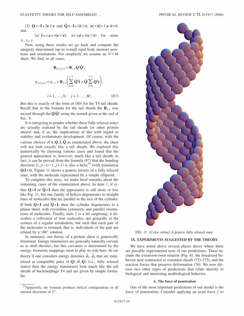
�2� Q=−I+2e � e and Q=−I+2e � e, �e�= �e�=1,e · e=0,and
�a� t=�1e+��e� e�, t=�2e+��e� e� for some�1 ,�2 ,�.
Now, using these results we go back and compute theuniquely determined �up to overall rigid body motion� posi-tions and orientations. For simplicity we assume an N�Msheet. We find, in all cases,
Ri+1,j+1 = R1,1QiQ j ,
yi+1,j+1 = y1,1 + R1,1�k=0
j−1
Qkt + Q jk=0
i−1
Qkt� ,
i = 1, . . . ,N, j = 1, . . . ,M . �87�
But this is exactly of the form of �40� for the T4 tail sheath.Recall that in the formula for the tail sheath the R1,1 was
moved through the QiQ j using the remark given at the end ofSec. V.
It is intriguing to ponder whether these fully relaxed statesare actually realized by the tail sheath �or other proteinsheets� and, if so, the implications of this with regard tostability and evolutionary development. Of course, with the
various choices of t ,Q , t ,Q as enumerated above, the sheetwill not look exactly like a tail sheath. We explored thisnumerically by choosing various cases and found that thegeneral appearance is, however, much like a tail sheath; infact, it can be proved from the formula �87� that the bondingdirection �i , j�− �i−1, j+1� is also a helix10 �with translationQ�t+ t�. Figure 11 shows a generic picture of a fully relaxedstate, with the molecule represented by a simple ellipsoid.
To complete this story, we make brief remarks about theremaining cases of the enumeration above. In item 1, if ei-
ther Q=I or Q=I then the appearance is still more or lesslike Fig. 11, but one family of helices degenerates to straightlines of molecules that are parallel to the axis of the cylinder.
If both Q=I and Q=I, then the cylinder degenerates to aplanar sheet, with crystalline symmetry, and parallel orienta-tions of molecules. Finally, item 2 is a bit surprising; it de-scribes a collection of four molecules, not generally at thecorners of a regular tetrahedron, but such that each pair ofthe molecules is twinned, that is, individuals of the pair arerelated by a 180° rotation.
In summary, our theory of a protein sheet is genericallyfrustrated. Energy minimizers are generally naturally curved,as in shell theories, but this curvature is determined by theenergy. Isometric mappings seem to play no role here. In our
theory if one considers energy densities 1 , 2 that are mini-
mized at compatible pairs �t ,Q� , �t ,Q� �i.e., fully relaxedstates� then the energy minimizers look much like the tailsheath of bacteriophage T4 and are given by simple formu-las.
IX. EXPERIMENTS SUGGESTED BY THE THEORY
We have noted above several places above where thereare possible experimental tests of our predictions. These in-clude the extension-twist relation �Fig. 6�, the linearized be-havior near contracted or extended sheath �72�–�75�, and thereaction forces that preserve deformation �76�. We now dis-cuss two other types of predictions that relate directly tobiological and interesting nonbiological behavior.
A. The force of penetration
One of the most important predictions of our model is theforce of penetration. Consider applying an axial force f to
10Apparently, the formula produces helical configurations in allrational directions of Z2.
FIG. 11. �Color online� A generic fully relaxed state.
ELASTICITY THEORY FOR SELF-ASSEMBLED … PHYSICAL REVIEW E 73, 011917 �2006�
011917-19

contracted sheath, so as to stress-induce the transformation toextended sheath. Alternatively, one can imagine applyingsufficient tension to extended sheath to just prevent contrac-tion, i.e., the stall force. We neglect the interactions with thetail tube, assuming it to be weakly bonded to the sheath evenwhen it is in the extended state, as is thought to be true�22,12�. For small values of f the behavior is given by theanalysis of �68�–�72�, and we expect the initial slope of theforce-elongation curve �f vs �−c� /c� given by the modu-lus c
2�AC−B2� /A. There is expected to be significant non-linearity of the response, because the constraints themselvesare nonlinear. The details of the response near transition maydepend on details of the loading device—whether hard orsoft, for example—but one expects some kind of load dropon nucleation. The transformation is expected to take placevia movement of an interface, as pictured qualitatively inFig. 8 and at approximately constant free energy, because abias of free energy toward either phase would, by energyminimization, tend to drive out the interface, one way or theother. This suggests the criterion
��yc,Rc� − 22f23c = ��ye,Re� − 22f23
e , �88�
where the uniform states �yc,e ,Rc,e�= �y1,1c,e ,R1,1
c,e , . . . ,y6,23
c,e ,R6,23c,e � are assumed to be in equilibrium. Let super-
scripted variables �e,c ,�e,c ,�e,c� be associated with theseuniform equilibrium states. Using the special form of theenergy �62�–�66�, we get
�c��c,c� − f�c/c� = �c��e,e� − f�e/c� , �89�
where
��c��c,e,c,e���
= 0,��c��c,e,c,e�
�=
f
c. �90�
Solving these together, we get
f = f trans =��c��e,e� − �c��c,c��c
�e − c�
=��c��e,e� − �c��c,c��
�e/c − 1�
+ O�maxc,e
Ac,e
Ac,eCc,e − Bc,e2 f2� . �91�
The error term depends also on geometric factors and can bewritten explicitly, but we note that it is of the form�f2/�tensile modulus��. Thus, if f��tensile modulus� then thisterm is negligible as compared to f , and the force at trans-formation is a simple ratio of the height difference betweenthe energy well minima at extended and contracted sheathand the difference between the lengths of the sheath. Thesekinds of results are well known in the study of phase trans-formations.
Of course, the virus uses the reverse transformation, fromextended to contracted sheath, during penetration. The maxi-mum force available for penetration is expected to be alsof trans.
We can evaluate the force of contraction based on theheight difference between the wells, accounting for the res-
ervations given at the end of Sec. VII C. Combining Eqs.�91� and �65�, we get,
f trans = 103 pN. �92�
By comparison, the stall force measured by laser tweezersduring DNA packaging in �29 was 57 pN �1�. We wouldtend to think that the number 103 is a lower estimate for theactual force, because �� is underestimated at 72 °C as ex-plained in Sec. VII C. If we divide this force by the cross-sectional area of the sheath to get a stress, we get about0.5 MPa. This is quite low as a �maximum� transformationstress in a macroscopic crystalline martensitic material.However, the transformation strain in the T4 sheath is enor-mous, so, if we calculate the energy density of contractionbased on these numbers, we get numbers that are comparableto those measured in the best shape memory materials, whichthemselves exhibit the highest energy densities in any knownactuator system �23�.
The transformation can also be induced by applying apure axial moment. This leads to the analog of �88�–�91�,except using the loading device energy −22M�, and givesthe moment at transformation of
M = Mtrans =��c��e,e� − �c��c,c��c
��e − �c�
=��c��e,e� − �c��c,c��c
�e − �c
+ O�maxc,e
Ac,e
Ac,eCc,e − Bc,e2 M2� . �93�
Neglecting the higher order terms in �91� and �93� we havethe simple approximate relationship between the forces andmoment needed to cause transformation in the sheath:
f trans ��e − �c
e − cMtrans = −
1
89 ÅMtrans. �94�
B. Biomolecular epitaxy, patterning and devices
In this section we explore some more speculative ideas.T4 tail sheath is a kind of biomolecular actuator, and onecould imagine that it could function as part of a manmademachine �24� that could interact in an intimate way withbiological organisms. Tubes of polysheath several microme-ters long have been synthesized �25,26�; polysheath is simi-lar to, but not exactly the same as, contracted sheath. Tubesof extended sheath have not been synthesized separate fromthe baseplate and tail tube, and this is understandable in viewof their higher free energy and also the possible role of thebaseplate in stabilizing the extended sheath via epitaxy.
One basic interesting line of thought is to consider thepossibility of changing the heights of the energy wells. As istrue in a great many biological systems, hydrophobicityplays a critical role, and this can be appreciated in the presentcase by looking at Fig. 4. There, it is clear by inspection thatextended sheath exposes substantially more surface area tothe surrounding solution than contracted sheath, and thisqualitatively explains its higher free energy. But it also indi-
W. FALK AND R. D. JAMES PHYSICAL REVIEW E 73, 011917 �2006�
011917-20

cates that the relative free energies of the extended and con-tracted sheaths are amenable to adjustment via manipulationof the solution chemistry. Systematic studies �26� of the ef-fect of solution chemistry on the breakup of parts of the virus�capsid, neck, tail sheath, tail tube, baseplate, tail fibers�demonstrate sensitivity to solution chemistry. Apparently, so-lutions that cause a contracted tail sheath to extend have notyet been found. However, if by this means one could ex-change the heights of the wells, then tail sheath would belike a shape memory material. In a highly schematic way,one could alter the solution so that extended sheath is stable.Then one could add an axial tensile force to the sheath.Again manipulating the solution, one could return it tophage-physiological conditions and, if the force was not toolarge �i.e., below the value f trans of �91�� then the sheathwould transform to the contracted form, while doing work onthe force. This would be a machine that converts chemicalfree energy of the solution to mechanical energy. The verysmall cross section of the sheath would allow it to target asmall region of a cell. One could consider the possibility ofvast arrays of these tubes. In this regard, we note that orderedplanar arrays of whole viruses have been deposited on sur-faces �not using epitaxy� by Lee et al. �27�.
In the following discussion we allow rather drasticchanges of the sheath, but we enforce the constraints �42�and �45�, these being in our view fundamental to its behav-ior. The T4 sheath is in the shape of a cylinder, but it isinteresting to think about the possibility of slitting along agenerator and unrolling it. We first note that it is possible todo this without violating the constraints. Second, the ex-tended tail sheath exhibits an epitaxial relation to the base-plate, and this likely plays a role in self-assembly of thesheath during formation and subsequent stabilization. Thuswe suggest the possibility of growing films of tail sheathepitaxially. In general, epitaxial growth is aided by a sub-strate with the same lattice parameters as the sheath, that is
also chemically compatible with the sheath. The most likelypossibility is to grow the lower free energy contracted form�see the left of Fig. 13 below, which shows the epitaxialsurface�. It is interesting to note that epitaxial growth of pro-tein sheets could possibly take advantage of the shapes ofmolecules and the presence of functional groups, in additionto the matching of lattice parameters and use of surfacechemistry, the latter principles familiar from the epitaxialgrowth of semiconductors.
While it does not violate the constraints, unrolling is apretty drastic distortion, so one can expect some deviation ofthe lattice vectors from the values t0
c,e , tc,e of Sec. VI. Nev-ertheless, in the analysis below, we do use those values, to-gether with the orientations R1,1
c,e . Without loss of generality�using frame indifference� we first rotate these vectors intothe 1,2 plane �we do not relabel the resulting vectors� and weapply the same rotations to the orientations. We plot the sheetas it0+ jt where i and j are integers.
The transformation matrix G that maps t0c , tc into t0
e , te isthe matrix
�0.053 − 1.088
0.999 1.543� . �95�
By direct calculation GTG has eigenvalues 2.06, 0.567. As isknown from the theory of martensitic transformations insheets,11 the fact that these values straddle 1 �i.e., 2.06�1�0.567� means that there are exactly two interfaces on thesheet where extended and contracted sheet meet compatibly.These are pictured in Fig. 13. We have rotated the sheetssuitably so that the interfaces are horizontal. The originalorientation can be inferred from the dark lines of atoms,which correspond to what was the main helix �cf. Fig. 5�before unrolling. A cross section of the interface on the rightis seen in Fig. 12.
Note that on the left of Fig. 13 the dark line of atoms isapproximately in the direction of the interface. This reflectsthe constraint, which embodies the idea that the two phasesare approximately equally stretched along this line. The rea-son that this line does not exactly coincide with the interfaceis related to the use of the effective radius, rather than theactual radius, in Eq. �42�. As mentioned above, the values of
11See, e.g., �29� which shows how to calculate these lines and thecorresponding deformations. The presence of these two interfaceswas first noticed by Olson and Hartman �7�.
FIG. 12. �Color online� Edge-on view, slightly below horizontal,of the interface between contracted �left� and extended �right�sheath.
FIG. 13. �Color online� The two compatible interfaces that sepa-rate extended �above� from contracted �below� sheath. In each casethe dark line of atoms was the main helix before unrolling thesheath.
FIG. 14. Shear-inducing the transformation from contracted toextended sheath. Drawn with the lattice parameters of extended andcontracted sheaths but with molecules represented by dots. Themolecules are released from the substrate except for the two darkstrips at the top and bottom of the sheet.
ELASTICITY THEORY FOR SELF-ASSEMBLED … PHYSICAL REVIEW E 73, 011917 �2006�
011917-21
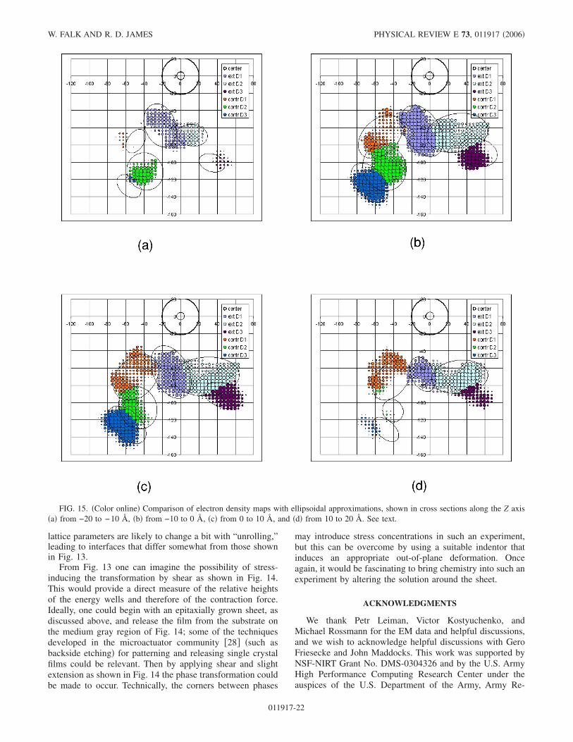
lattice parameters are likely to change a bit with “unrolling,”leading to interfaces that differ somewhat from those shownin Fig. 13.
From Fig. 13 one can imagine the possibility of stress-inducing the transformation by shear as shown in Fig. 14.This would provide a direct measure of the relative heightsof the energy wells and therefore of the contraction force.Ideally, one could begin with an epitaxially grown sheet, asdiscussed above, and release the film from the substrate onthe medium gray region of Fig. 14; some of the techniquesdeveloped in the microactuator community �28� �such asbackside etching� for patterning and releasing single crystalfilms could be relevant. Then by applying shear and slightextension as shown in Fig. 14 the phase transformation couldbe made to occur. Technically, the corners between phases
may introduce stress concentrations in such an experiment,but this can be overcome by using a suitable indentor thatinduces an appropriate out-of-plane deformation. Onceagain, it would be fascinating to bring chemistry into such anexperiment by altering the solution around the sheet.
ACKNOWLEDGMENTS
We thank Petr Leiman, Victor Kostyuchenko, andMichael Rossmann for the EM data and helpful discussions,and we wish to acknowledge helpful discussions with GeroFriesecke and John Maddocks. This work was supported byNSF-NIRT Grant No. DMS-0304326 and by the U.S. ArmyHigh Performance Computing Research Center under theauspices of the U.S. Department of the Army, Army Re-
FIG. 15. �Color online� Comparison of electron density maps with ellipsoidal approximations, shown in cross sections along the Z axis�a� from −20 to −10 Å, �b� from −10 to 0 Å, �c� from 0 to 10 Å, and �d� from 10 to 20 Å. See text.
W. FALK AND R. D. JAMES PHYSICAL REVIEW E 73, 011917 �2006�
011917-22

search Laboratory cooperative agreement No. DAAD 191-01-2-0014.
APPENDIX: APPROXIMATION OF ELECTRON DENSITYMAPS
Many arguments of this paper relied on the approximateshape and orientation of the molecules. In order to have areasonable but fairly simple representation of the moleculesof the tail sheath, we approximated the electron density mapsof Leiman et al. ��11�; we are grateful to Petr Leiman forproviding prepublication data from high resolution cryoelec-tron micrographs of the extended sheath�. Information abouthow the positions and orientations were extracted from therepresentations is given at the end of Sec. VI A.
The maps themselves showed clearly the presence of do-mains. These have the general appearance of nestled ellip-soids, so we approximated them by overlapping ellipsoids.We did this by partitioning the data by domain �the coloredregions of Fig. 15�. Then we computed the total electronic
charge and center of mass of each domain. Using chargeneutrality we made mass density proportional to electronicdensity. This can have errors arising mainly from the pres-ence of H atoms, but in fact the total charge of a domain �ormolecule� in the contracted vs the extended state differed bymore than this error, so the quality of the data did not justifya more detailed analysis.
With the center of mass of the domain now fixed, weadjusted the principal axes of the ellipsoids to match ap-proximately the sectional data. Sections of the selected ellip-soids are shown in Fig. 15 superimposed on the data. In thisfigure the concentric circles define the axis of the tail sheathand the Z values indicate the slices of the electron densitymap which were averaged. Here Z is an axial variable mea-sured from a fixed �but arbitrary� reference. Domains forboth extended and contracted sheath are shown. The ellipsesare sections of the ellipsoid �for the enclosed domain� at thecorresponding average value of Z �i.e., for Z=0–10 the slicethrough the ellipsoid was taken at Z=5�.
�1� D. E. Smith, S. J. Tans, S. B. Smith, S. Grimes, D. L. Ander-son, and C. Bustamante, Nature �London� 413, 748 �2001�.
�2� I. L. Ivanoska, P. J. de Pablo, B. Ibarra, G. Sgalari, F. C.MacKintosh, J. L. Carrascosa, C. F. Schmidt, and G. J. L.Wuite, Proc. Natl. Acad. Sci. U.S.A. 101, 7600 �2004�.
�3� J. F. Marko and E. D. Siggia, Macromolecules 28, 8759�1995�.
�4� N. Chouaieb and J. H. Maddocks, J. Elast. 77, 221 �2004�.�5� M. Moakher and J. H. Maddocks, Arch. Ration. Mech. Anal.
177, 53 �2005�.�6� F. A. Eiserling, in Bacteriophage T4, edited by C. K. Mathews
�American Society of Microbiology, Washington, D.C., 1983�,pp. 11–24.
�7� G. B. Olson and H. Hartman, J. Phys. �Paris�, Colloq. 43,C4-855 �1982�.
�8� H. R. Crane, Sci. Mon. 70, 376 �1950�.�9� J. L. Ericksen, in Advances in Applied Mechanics, edited by
C.-S. Yih �Academic Press, New York, 1977�, Vol. 17, pp.189–244.
�10� M. G. Rossmann, V. V. Mesyanzhinov, F. Arisaka, and P. G.Leiman, Curr. Opin. Struct. Biol. 14, 171 �2004�.
�11� P. G. Leiman, P. R. Chipman, V. A. Kostyuchenko, V. V. Me-syanzhinov, and M. G. Rossmann, Cell 118, 419 �2004�.
�12� V. A. Kostyuchenko, P. R. Chipman, P. G. Leiman, F. Arisaka,V. V. Mesyanzhinov, and M. G. Rossmann, Nat. Struct. Mol.Biol. 12, 810 �2005�.
�13� L. Pauling, Discuss. Faraday Soc. 13, 170 �1953�.�14� P. G. de Gennes, The Physics of Liquid Crystals �Oxford Uni-
versity Press, Oxford, 1974�.�15� M. F. Moody, J. Mol. Biol. 80, 618 �1973�.�16� R. D. James and K. F. Hane, Acta Mater. 48, 197 �2000�.�17� F. Arisaka, J. Engel, and H. Klump, Prog. Clin. Biol. Res. 64,
365 �1981�.�18� P. K. Purohit, J. Kondev, and R. Phillips, Proc. Natl. Acad. Sci.
U.S.A. 100, 3173 �2003�.�19� M. Arroyo and T. Belytschko, J. Mech. Phys. Solids 50, 1941
�2002�.�20� G. Friesecke, R. D. James, and S. Müller, Arch. Ration. Mech.
Anal. �to be published�.�21� J. P. Sethna, Phys. Rev. B 31, 6278 �1985�.�22� N. R. M. Watts and D. H. Coombs, J. Virol. 64, 143 �1990�.�23� P. Krulevitch, A. P. Lee, P. B. Ramsey, J. C. Trevino, J. Hamil-
ton, and M. A. Northrup, J. Microelectromech. Syst. 5, 270�1996�.
�24� K. Bhattacharya and R. D. James, Science 307, 53 �2005�.�25� E. Kellenberger and E. Boy De La Tour, J. Ultrastruct. Res.
11, 545 �1964�.�26� C. M. To, E. Kellenberger, and A. Eisenstark, J. Mol. Biol. 46,
493 �1969�.�27� S. Lee, C. Mao, C. E. Flynn, and A. M. Belcher, Science 296,
892 �2002�.�28� J. W. Dong, J. Q. Xie, J. Lu, C. Adelmann, C. J. Palmstrom, J.
Cui, Q. Pan, R. D. James, and S. McKernan, J. Appl. Phys. 95,2593 �2004�.
�29� K. Bhattacharya and R. D. James, J. Mech. Phys. Solids 46,531 �1999�.
ELASTICITY THEORY FOR SELF-ASSEMBLED … PHYSICAL REVIEW E 73, 011917 �2006�
011917-23