elastic stability of cylindrical sandwich … problem to which the method is applied is that of the...
TRANSCRIPT

U.S. DEPARTMENT OF AGRICULTURE • FOREST SERVICE • FOREST PRODUCTS LABORATORY • MADISON, WIS. In Cooperation with the University of Wisconsin
U. S. FOREST SERVICE RESEARCH NOTE
FPL-0173 OCTOBER 1967
ELASTIC STABILITY OF CYLINDRICAL SANDWICH SHELLS UNDER AXIAL
AND LATERAL LOAD

Summary
Presents a linear solution for determining the effect of combined axial and lateral loads under which a cylindrical sandwich shell will buckle. The facings of the sandwich cylinder are treated as homogeneous isotropic cylindrical shells and the core as an orthotropic elastic body. The characteristic determinant that represents the solution to the problem is solved numerically. Curves are given that show how the buckling load changes as the parameters of the problem change.

ELASTIC STABILITY OF CYLINDRICAL SANDWICH SHELLS
UNDER AXIAL AND LATERAL LOAD1
By
A. CARL MAKI, Engineer
2Forest Products Laboratory, Forest Service U.S. Department of Agriculture
Introduction
Sandwich construction is a result of the search for a strong, stiff, and yet light weight material. It is usually made by gluing relatively thin sheets of a strong material to the faces of relatively thick but light weight, and often weak, material. The outer sheets are called facings and the inner layer is called the core.
Such a layered system presents difficult design problems. What is offered here is a straightforward method for dealing with some of these problems.
The problem to which the method is applied is that of the elastic stability of a sandwich cylinder under uniform external lateral load and uniform axial load.
Notation
r, θ, z radial, tangential, and longitudinal coordinates, respectively
a radius to middle surface of outer facing
b radius to middle surface of inner facing
r mean radius m
t thickness of each facing
1This Research Note is a revision, under the same title, of Forest Products Laboratory
Report 1852, issued in 1955. It was originally prepared by Everett E. Haft, and issued as one of a series by the Forest Products Laboratory in cooperation with the U.S. Navy, Bureau of Aeronautics.
2Maintained at Madison, Wis., in cooperation with the University of Wisconsin.
FPL-0173

L length of cylinder
E modulus of elasticity of facings
µ Poisson’s ratio of facings
G modulus of rigidity of facings
Ec modulus of elasticity of core in direction normal to facings
Grθ modulus of rigidity of core in rθ plane
G modulus of rigidity of core in rz planerz
q intensity of uniform external lateral loading
k
σ r normal stress in core in radial direction
τ rθ, τ rz transverse shear stresses in core
u, v, w radial, tangential, and longitudinal displacements, respectively
n number of waves in circumference of buckled cylinder
m number of half waves in length of buckled cylinder
V rθ
V rz
λ mγ
γ
δnθ
FPL-0173 -2-

--
δz
N N , N normal forces and shear force per unit length of facingθ, z θz
Qθ , Q z
M , M θ z
M , M zθ θz
X, Y, Z
A
R
P
transverse shear forces per unit length of facing
bending moments per unit length of facing
twisting moments per unit length of facing
surface forces per unit area of facing
the value of the lateral load parameter φ 1
when the axial load parameter φ2 is equivalent to zero
the value of the axial load parameter φ 2
when the lateral load parameter φ1 is equivalent to zero
natural logarithm
total axial load
A, B, C, D, K, E, A' , B' A", B" arbitrary constants
note any of the above term that appear with a prime (as N ' ) refer to the inner facing. z
FPL-0173 -3-
β
φ1
φ2
φ1
φ2
1n
h

Z M 105 662
Figure I.--Sandrich cylinder.
M 133 627
Figure 2.--Differential elements of core and facings before buckling.
FPL-0173 -4-

Mathematical Analysis
As previously stated, the core is relatively weak. Because of the high strength of the facings the core need carry little tension or compression except in a direction perpendicular to the facings. The facings are able to resist shearing deformation in their plane and it is necessary only that the core be able to resist shear in the radial direction in planes perpendicular to the facings. In this analysis, the core is considered to be an orthotropic elastic body. It is unable to resist deformations other than those just mentioned.
Interdependence of the core and the facings is gained by equating their displacements at the interfaces. To simplify the analysis, the core is assumed to extend to the middle surface of each facing.
Figure 1 shows the cylinder and the coordinates that are used.
Prebuckling Stresses
Before buckling occurs, the cylinder is in a state of uniform compression. The axial load is carried. by the facings since the core material is assumed to be incapable of carrying load in this direction. With facings of like material, the stress is the same in both facings. Since the facings have the same thickness, then the loading per unit length of facing, N or N z ' , will be the same, This means that for a total load P z
The calculation of stresses due to the lateral pressure is a problem in rotational symmetry. Differential elements of the core and of the facings are shown in figure 2.
Summing forces in the radial direction gives for the core
for the outer facing
and for the inner facing
FPL-0173 -5-

, these equations can be solved for s r , N θ, and N θ ' .
As P and q increase, N , N ', N , N ' and σ also increase. Eventually a condition myz z θ θ r be reached where a slight increase in load caues the cylinder to lose its state of uniform compression and buckle as a result of elastic instability. This buckling is assumed to cause only a small change in the stress distribution. These small changes will now be considered.
Buckling Stresses
The core.--A free body diagram of an element of the core is shown in figure 3.
Neglecting term which are products of more than three difterentials, a summation of forces in the r, θ and z direction gives
(1)
(2)
(3)
Equation (2) my be integrated to give
(4)
3 RaviIle, M. E. Analysis of long cylinders of sandwich construction under uniform
external lateral pressure, Forest Products Laboratory Report 1844, 1954.
FPL-0173 -6-

Figure 3.--DifferentiaI element of deformed core. Z M 105 664
Equation (3) may be integrated to give
(5)
(6)
(7)
(8)
It is convenient to assume the displacements u, v, and w in the form
(9)
(10)
(11)
This form will permit a unique determination of f1
(r), f2
(r), and f3
(r); assumes n cir
cumferential waves and m longitudinal half waves upon buckling; results in zero displacements in the radial and circumferential directions at the ends; and imposes no moment upon the facings at the ends,
FPL-0173 -7-

From a consideration of equations (4), (5), (7), (8), (9), (10), and (11) it can be shown that
(12)
(13)
Substituting equation (9) into (6) and then equations (6), (12), and (13) into equation (1) gives
(14)
which upon integration shows that
(15)
Equations (9), (10), and (12) are substituted into equation (7) to give
(16)
from which
(17)
Equations (9), (11), and (13) are substituted into equation (8) to give
(18)
from which
(19)
It is convenient to have the constants of f1(r), f2(r), and f3 (r) in nondinnaensional form.
Redefining the constants , the following form is obtained.
(20)
FPL-0173 -8-

-9-

(21)
(22)
The facings.--Since the problem of stability of homogeneous cylindrical shells has been solved by other authors, it is only necessary in the stability analysis of cylindrical sandwich shells to consider it as a composite of two homogeneous shells bonded together by an elastic core subject to the compatibility requirements of equal displacements at their interfaces, which, to simplify the analysis, is assumed to extend to the middle surface of each facing.
Free body diagrams of a facing element showing the sense of the forces and moments are found in figures 4 and 5.
Z M 106 302
Figure 5.--Differentlal element of facing showing moments and twists.
The equations of equilibrium for the facings can be obtained from a mathematical theory of thin shells. It is felt that for a small deflection analysis the theories presented by various authors differ principally in second-order effects, as is evidenced by comparing the work of Flugge4 and Timoshenko5 on the buckling of cylindrical shells.
4FIugge, W. Stresses in Shells, Springer-Verlag, Berlin, 1962.
5Timoshenko, S. Theory of Elastic Stability, McGraw-Hill, 1936.
FPL-0173 -10-

As a result, the equations of equilibrium as presented by Timoshenko and subject to the necessary transformations will be used here. Such theory, when applied to cylindrical shells of radius r; yields the following differential equations:
(23)
(24)
(25)
(26)
(27)
(28)
FPL-0173 -11-

Assuming that resultant forces other than Nθ and Nz are small and neglecting products
of these forces and the displacements u, v, and w which are also small, and assuming further a membrane analysis where the bending moments and transverse shear forces
in the individual facings are neglected, the equilibrium equations can be reduced to:
(29)
(30)
(31)
Evaluating equations (29), (30), and (31) for each facing or when r = a and r = b and satisfying the compatibility requirements at these interfaces provide the six equations necessary for the determination of the six arbitrary constants found in expressions 20, 21, and 22.
Mathematical Analysis
N z and N θ of equations (29), and (31) are
respectively, for the outer facing and by
replaced by
pectively, for the inner facing (primes denote inner facing). This is necessary because the forces in the buckled shell are the prebuckling forces plus the forces due to buckling. The N
z, N
z Nq, and N θ ' are small forces due to buckling which are later to be expressed
in terms of displacements, (which are assumed to have differed negligibly from the prebuckled state), and the product of these small forces and the displacements are also neglected. Expressions (29), (30), and (31), as evaluated for the outer facing then become:
(32)
(33)
(34)
FPL-0173 -12-

As is customary in such stability problems, the stretching of the middle surface is taken into account by assuming that the prebuckling stress resultants are very large in comparison with the other stress resultants; thus the terms
and
should be substituted for the quantities and qa(1 - k), respectively, and the surface
forces X, Y, and Z should be multiplied by (1 + εθ)(l + εz) in equations (32) to (34). In these expressions
(35)
Finally, the expressions for the forces, moments, and twists along with the relationships for the surface faces:
(36)
are expressed in terms of u, v, and w and substituted in (32), (33), and (34). They lead to the following equations for the outer facing:
(37)
(38)
(39)
where φ and φ are as defined under notations.1 2
FPL-0173 -13-

To achieve proper interaction between the core and the facings, the displacements of the middle surfaces of the facing are set equal to the displacements of the core at r = a and r = b.
Thus, displacements u, v, and w in equations (37), (38), and (39) are replaced by equations (20), (21), and (22) evaluated at r = a. In this manner, three equations in six arbitrary constants (A, B, C, D, E, and F) are written for the outer facing. In a like fashion, three equations are written for the inner facing. These equations can then be written in matrix form as:
(40)
where the aij’s are defined in terms of geometric, loading, and material parameters.
Equations (40) are satisfied if the constants A, B, C, D, F, and L are all equal to zero. This represents the uniformly compressed circular form of equilibrium of the cylinder. A buckled form of equilibrium is possible only if equations (40) yield nonzero solutions for the constants. This requires that the determinant of the coefficients of these constants be equal to zero.
It is possible to find simultaneous minimum values (absolute sense) of φ 1
and φ 2
for
which these six equations will be satisfied for any values of the arbitrary constants. Mathematically this means that for such a combination of loads and material parameters the deflections are indeterminate. The shell becomes elastically unstable and the loads that bring about this condition are the desired critical loads.
Numerical Computations
A literal solution of the sixth order determinant for the eigenvalues (φ1, φ2) is not
feasible. A numerical solution, from which curves may be drawn, is possible if a digital computer is used.
For sandwich construction, particularly for that utilizing honeycomb cores, the equations can be greatly simplified by assuming E = ∞. This substitution is common with c
this type of construction due to the small relative displacement occurring between the
FPL-0173 -14-

sandwich facings. Indications are that analyses based on this assumption are sufficiently accurate in most ranges, but for relatively short cylinders having weak cores such an assumption may result in serious error.
Poisson's ratio for the facings can be taken as one-third and the value of k closely approximated by the fraction one-half for most cylinders where the radius is large compared to the sandwich thickness h.
Making these substitutions, the a aij's in equations (40) are found to be
FPL-0173 -15-
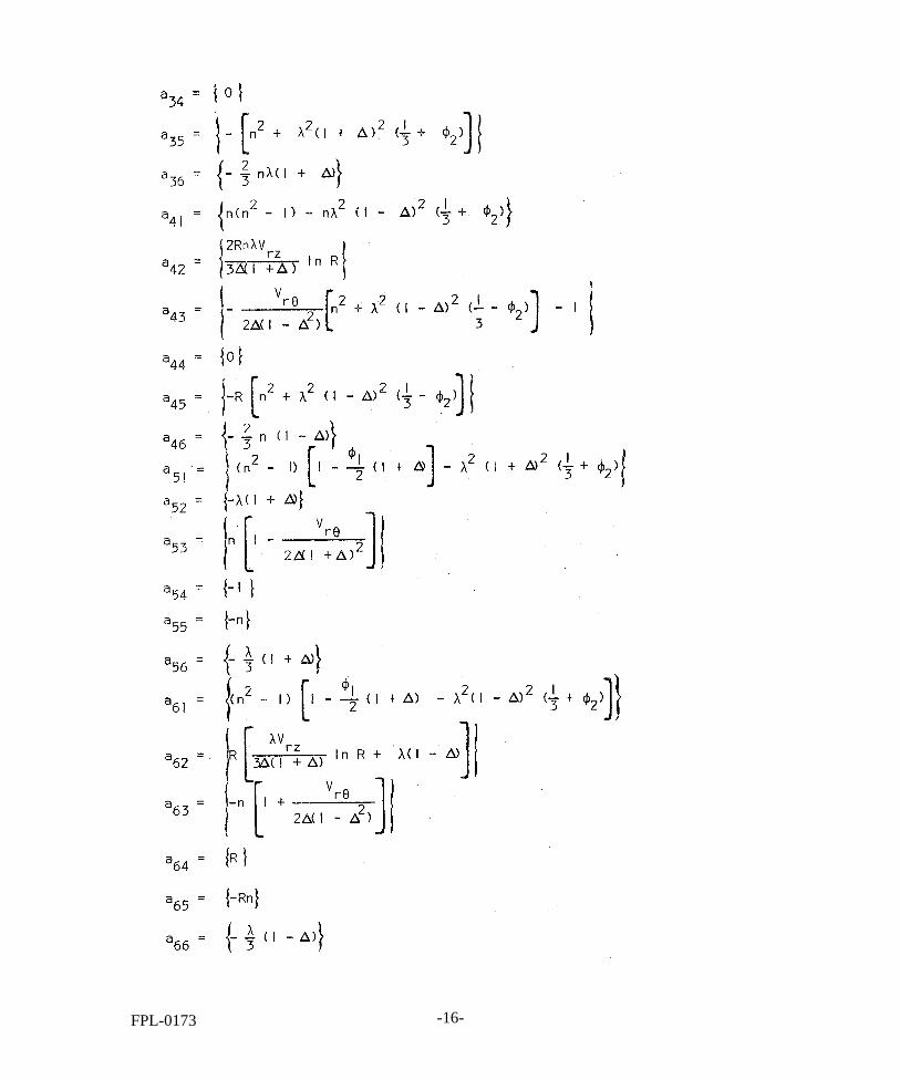
FPL-0173 -16-

The problem is now reduced to developing a search technique whereby minimum values of φ 1
and φ2
can be determined for given values of V rq’ V rz , ∆, and γ, such that the
determinant goes to zero.
This problem was programed for the digital computer and results are presented in figures 6, 7, and 8. The solutions show a linear relationship between φ
1and φ
2as was
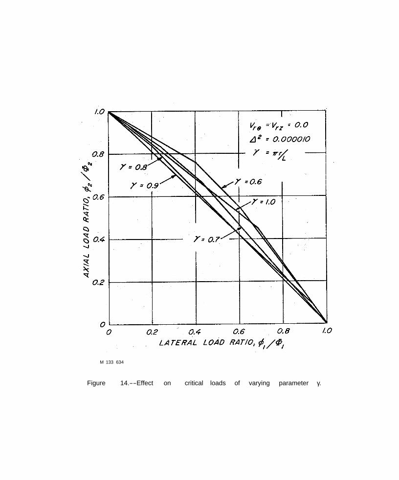
found previously for isotropic shells 5,6 wherein the slopes of the lines are dependent upon values of number of buckles producing minimum loads. The lowest of these lines are shown in figures 6, 7, and 8 for chosen values of γ. These figures were then used as a basis for plotting figures 9, 10, 11, 13, 14, 16, and 17, which clarify the effect of the interaction of the loads by presenting them in terms of ratios.
The effect of special cases such as the hydrostatic case can be seen most clearly on figures 6, 7, and 8 by the use of a load ratio line where the slope of the line and the desired load ratio are equivalent. The hydrostatic case, for example, has a load ratio of one-fourth or
Discussion of Results
For illustrative purposes, the three values of of 0.0001, 0.00001, and 0.000001
were chosen to represent the range of delta. For a given delta then, figures are presented which show the effect on the critical loads of (1) varying the value of γ while holding the values of Vrz and Vrθ a constant, and (2) varying the value of V rz and V rθ while holding
the value of a constant.
The results of this analysis agree favorably with those previously presented 6,7 for lateral pressure and axial load acting separately. These values then represent the values used for φ 1 and φ
2 in the figures.
6 Kuenzi, E. W., Bohannan, B., and Stevens, G.H. Buckling Coefficients for Sandwich Cylinders of Finite Length Under Unifom External Lateral Pressure. U.S. Forest Service Research Note FPL-0104. 1965. Forest Prod. Lab.
7 Zahn, John W.,and Kuenzi, Edward W. Classical Buckling of Cylinders of Sandwich Construction in Axial Compression--Orthotropic Cores. U.S. Forest Service Research Note FPL-018. 1963. Forest Prod; Lab.
FPE-0173 -17- .67-30


M 133 630
Figure 7.--Effect of combined loading for D2 = 0.0001.


M 133 639
Figure 9.--Effect on critical loads of varying parameter γ.

M 133 635
Figure 10.--Effect on critical loads of varying parameter γ.

M 133 629
Figure 11.--Effect on critical loads of varying parameter γ.

M 133 640
Figure 12.--Effect on critical loads of varying parameters Vrθ and Vrz.

M 133 642
Figure 13.--Effect on the critical loads of varying parametere γ.
M 133 634
Figure 14.--Effect on critical loads of varying parameter γ.

M 133 641
Figure 15.--Effect on critical loads of varying parameters Vrθ and Vrz.

M 133 636
Figure 16.--Effect on critical loads of varying parameter γ.

M 133 637
Figure 17.--Effect on critical loads of varying parameter γ.

Figure 18.--Effect on critical loads of varying parameters Vrθ and Vrz.

M 133 628
Figure 19.--Classical buckling coefficient for sandwich cylinders with isotropic facings and orthotropic core.

PUBLICATION LISTS ISSUED BY THE
FOREST PRODUCTS LABORATORY
The following lists of publications Forest Products Laboratory or relate able upon request:
Architects, Builders, Engineers, and Retail Lumbermen
Box and Crate Construction and Packaging Data
Chemistry of Wood
Drying of Wood
Fire Performance
Fungus and Insect Defects in, Forest Products
Furniture Manufacturers, Woodworkers, and Teachers of Woodshop Practice
Glue and Plywood
Growth, Structure, and Identification of Wood
deal with investigative projects of the to special interest groups and are avail-
Logging, Milling, and Utilization of Timber Products
Mechanical Properties and Structural Uses of Wood and Wood Products
Modified Woods, Paper-Base Laminates, and Reinforced Plastic Laminates
Sandwich Construction
Thermal Properties of Wood
Wood Fiber Products
Wood Finishing Subjects
Wood Preservation
Note: Since Forest Products Laboratory publications are so varied in subject matter, no single catalog of titles is issued. Instead, a listing is made for each area of Laboratory research. Twice a year, January 1 and July 1, a list is compiled showing new reports for the previous 6 months. This is the only item sent regularly to the Laboratory's mailing roster, and it serves to keep current the various subject matter listings. Names may be added to the mailing roster upon request.

The FOREST SERVICE of the U. S. DEPARTMENT OF AGRICULTURE is dedicated to the principle of multiple use management of the Nation's forest resources for sustained yields of wood, water, forage, wildlife, and recreation. Through forestry research, cooperation with the States and private forest owners, and management of the National Forests and National Grasslands, it strives - as directed by Congress - to provide increasingly greater service to a growing Nation.