elastic-plastic buckling of infinitel y long …digitool.library.mcgill.ca/thesisfile100237.pdf ·...
TRANSCRIPT

ELASTIC-PLASTIC BUCKLING OF
INFINITEL Y LONG PLATES RESTING ON
TENSIONLESS FOUNDATIONS
by
Y ongchang Yang
Department of Civil Engineering and Applied Mechanics
McGill University
Montreal, Quebec, Canada
April 2007
A thesis submitted to the Graduate and Postdoctoral Studies Office
in partial fulfilment of the requirements of the degree of
Master of Engineering

1+1 Libraryand Archives Canada
Bibliothèque et Archives Canada
Published Heritage Branch
Direction du Patrimoine de l'édition
395 Wellington Street Ottawa ON K1A ON4 Canada
395, rue Wellington Ottawa ON K1A ON4 Canada
NOTICE: The author has granted a nonexclusive license allowing Library and Archives Canada to reproduce, publish, archive, preserve, conserve, communicate to the public by telecommunication or on the Internet, loan, distribute and sell theses worldwide, for commercial or noncommercial purposes, in microform, paper, electronic and/or any other formats.
The author retains copyright ownership and moral rights in this thesis. Neither the thesis nor substantial extracts from it may be printed or otherwise reproduced without the author's permission.
ln compliance with the Canadian Privacy Act some supporting forms may have been removed from this thesis.
While these forms may be included in the document page count, their removal does not represent any loss of content from the thesis.
• •• Canada
AVIS:
Your file Votre référence ISBN: 978-0-494-38497-8 Our file Notre référence ISBN: 978-0-494-38497-8
L'auteur a accordé une licence non exclusive permettant à la Bibliothèque et Archives Canada de reproduire, publier, archiver, sauvegarder, conserver, transmettre au public par télécommunication ou par l'Internet, prêter, distribuer et vendre des thèses partout dans le monde, à des fins commerciales ou autres, sur support microforme, papier, électronique et/ou autres formats.
L'auteur conserve la propriété du droit d'auteur et des droits moraux qui protège cette thèse. Ni la thèse ni des extraits substantiels de celle-ci ne doivent être imprimés ou autrement reproduits sans son autorisation.
Conformément à la loi canadienne sur la protection de la vie privée, quelques formulaires secondaires ont été enlevés de cette thèse.
Bien que ces formulaires aient inclus dans la pagination, il n'y aura aucun contenu manquant.

Abstract
There is a c1ass of plate buckling problems in which buckling occurs in the presence of a
constraining medium. This type of buckling has been investigated by many researchers,
mainly as buckling of elastic columns and plates on elastic foundations. Analytical
solutions have been obtained by assuming the foundation to provide tensile as well as
compressive reaction forces. The present work differs from the previous ones in two
respects. One, the foundation is assumed to be one-sided, thus providing only the
compressive resistance. Two, the plates are allowed to be stressed in the plastic, strain
hardening range. Equations for determining the buckling stresses and wave1engths are
obtained by solving the differential equations for simply supported and c1amped long
rectangular plates stressed uniformly in the longitudinal direction. The relevance and the
usefulness of the obtained formulas is demonstrated by comparing the predicted results
with the experimental results of other researchers on buckling of concrete filled steel box
section and HSS columns. It is shown that the theoretical buckling loads match quite
c10sely with the experimental ones, and hence, should prove useful in formulating mIes
for the design of such columns.
-i-

Résumé
Il Y a une catégorie de problèmes liés au voilement des plaques minces dans lesquels le
flambage se produit en présence d'un milieu de contrainte. Ce type de flambage a été
considérablement étudié par les chercheurs comme étant un problème de flambage de
colonnes et des plaques élastiques sur fondation élastique. Des solutions analytiques ont
été obtenues en supposant que la fondation fournit de forces de réaction compressives
aussi bien que de tension. Le travail actuel diffère du précédent à deux égards.
Premièrement, on suppose que la fondation ne peut fournir que des réactions
compressives. Deuxièmement, les plaques sont sollicitées dans le domaine post-élastique.
Des formules pour les charges de flambage et les longueurs d'onde décrivant les modes de
flambage sont obtenues, en résolvant les équations différentielles pour les cas des plaques
longues rectangulaires soumises à un effort uniforme en direction longitudinale. La
pertinence et l'utilité des formules obtenues sont démontrées en comparant les résultats
prédits avec des résultats expérimentaux obtenus par d'autres chercheurs pour le
flambage de tubes rectangulaires en acier remplis de béton et des colonnes tubulaires de
type HSS. On remarque que les prédictions du flambage théorique sont très similaires
aux résultats expérimentaux. En conséquence, le modèle théorique devrait s'avérer utile
pour formuler des règles pour la conception de colonnes de ce type.
-ii-

Acknowledgments
l would like to express sincere thanks to my research supervisor Professor S. C.
Shrivastava of Department of Civil Engineering and Applied Mechanics, McGill
University, whose help, stimulating suggestions, and encouragement helped me at all
times in doing the research and writing this thesis.
l would like to express special thanks to my wife Weixia, whose love, patience, and
unwavering support enabled me to complete this work.
-111-

Table of Contents
Abstract ................................................................................................................. ..
Resume (French) ................................... ........................... ......... ....... .............. ......... 11
Acknowledgments .. ................ .............................. .................. .................... ............. iii
Table of Contents .................................................................................................... IV
List of Major Symbols ............................................................................................ VI
List of Figures ......................................................................................................... viii
List of Tables .......................................................................................................... x
Chapter 1 Introduction ........................................................................................ 1
1.1 Definition of the problem ................................................................................. 1
1.2 Literature review .............................................................................................. 6
1.3 Statement of the objectives ............................................................................... 9
Chapter 2 Elastic Buckling of Infinitely Long Plates on Elastic Foundations 10
2.1 Goveming equations of equilibrium ................................................................. 10
2.2 Buckling deflections in contact and no-contact zones ...................................... 17
2.2.1 Solution for buckling deflections in contact zones .................................. 17
2.2.2 Solution for buckling deflections in no-contact zones . ............... ............. 19
2.3 Matching conditions between contact and no-contact regions ......................... 21
2.4 Equations for buckling loads and wavelengths by the equilibrium method ..... 23
2.5 Equations for buckling loads and wavelengths by the method ofvirtual work 25
2.6 Solutions ofbuckling loads and wavelengths under simply supported edges '" 29
2.7 Solutions ofbuckling loads and wavelengths under c1amped edges 33
Chapter 3 Plastic Buckling of Infinitely Long Plates Resting
on Elastic Foundations ...................................................................... 36
3.1 Constitutive relations of the plasticity theories ................................................. 36
3.2 Constitutive relations for a plastic bifurcation analysis .................................... 39
3.3 Equations for buckling loads and wavelengths by the equilibrium method ..... 41
-IV-

3.3.1 Equations for buckling displacements in the contact and no-contact
regions .................................................................................................... 42
3.3.2 Derivation of the buckling equations ....................................................... 43
3.4 Equations for buckling loads and wavelengths by the method of virtual work 44
3.5 Buckling loads and wavelengths for simply supported plates .......................... 45
3.6 Buckling loads and wavelengths for clamped plates ........................................ 50
Chapter 4 Application to Concrete-filled Steel Box Columns, and
Verifications with Experiments ........................................................ 53
4.1 Application to concrete-filled steel box columns ............................................. 53
4.2 Verification with experiments ........................................................................... 57
Chapter 5 Summary and Conclusions 66
5.1 Summary ........................................................................................................... 66
5.2 Conclusions ....................................................................................................... 69
5.3 Suggestions for future work .............................................................................. 69
References .... ............... ...... ........... ........................... ...... .......... ...... ...... ........ ........... 71
-v-

~ ..
a
b
Ac, As
B,C,D,F
B',C',D',F'
cl' dl
C2, d2
e, 9
D
E
Et
Es
J2
f~ G
k
Mxx, Myy, Mxy N cr
Nc
N s
NT
Nu
t
List of Major Symbols
plate length
plate width
area of concrete core, area of steel section
general moduli for plate buckling analysis
elastic-plastic moduli in plastic plate buckling
related to roots of the characteristic equation in the contact part
related to roots of the characteristic equation in the no-contact part
parameters in elastic-plastic moduli, e = E / Es - 1, 9 = E / Et
elastic rigidity of a plate
y oung's modulus of elasticity
tangent modulus
secant modulus
second invariant of the deviatoric stress Sij, J2 = ~SijSij crushing strength of concrete in cylinder test
shear modulus
modulus of elastic foundation
moment stress resultants per unit length
buckling load per unit length ( = acr t)
ultimate strength ofconcrete core (= O.85f~ Ac)
bifurcation load of the steel section of the column ( = a crAs)
the capacity predicted by the present theory for the column
the capacity obtained in experiments for the box columna
deviatoric stress components, Sij = aij - !akkDij
plate thickness
WI (Xl, y), W2 (X2, y) buckling deflections in contact and no-contact regions
x,y,z coordinate directions
foundation modulus parameter ( = kb4 /1[4 D)
coefficients of differential equations in contact and no-contact zones
elastic buckling of simply supported plates
coefficients of differential equations in contact and no-contact
zones elastic buckling of clamped plates
-Vl-

(PI (Xl)
<P2 (X2) if; (y) À
1/
2(,2ç
coefficients of differential equations in contact and no-contact
zones plastic buckling of simply supported plates
coefficients of differential equations in contact and no-contact zones
plastic buckling of clamped plates
plate strains due to buckling, fij
buckling function in x direction, contact part x = Xl
buckling function in x direction, no-contact part x = X2
buckling function in y direction
buckling load parameter for a plate ( = Ncrb2 /7r2 D)
J-L = 7r/b
Poisson's ratio
plate stresses due to buckling, (Jij
von Mises equivalent stress, (Je = J3J; = J~SijSij yield stress of steel
buckle lengths, contact and no-contact parts
-Vll-

List of Figures
Figure 1-1 Concrete-filled steel box section column [1] ....................................... 2
Figure 1-2 Delamination in a composite plate - buckling mode ............................ 2
Figure 1-3 Buckling modes of short plates ............................................................ 3
Figure 1-4 Buckling mode of an infinitely long plate resting on a one-way elastic
foundation, showing zones of contact and no-contact ......................... 4
Figure 2-1 Buckling mode of an infinitely long plate constrained unilaterally
by an elastic foundation ....................................................................... Il
Figure 2-2 Forces and moments acting on a plate coordinate element .................. Il
Figure 2-3 Longitudinal section ofbuckling mode ofan infinitely long plate resting
on a one-way elastic foundation ...... .......... ......... ........ ...... ....... ......... ..... 16
Figure 2-4 Buckling load coefficient - foundation stiffness parameter curves with
different boundary conditions ......... ................... ........ ...... ........ ........ .... 31
Figure 2-5 Wavelength to width ratio - foundation stiffness parameter curves with
simply supported unloaded edges ....................................................... .
Figure 2-6 Elastic buckling mode of an infinite plate resting on a rigid foundation
Figure 2-7 Wavelength to width ratio - foundation stiffness parameter curves with
32
32
clamped edges ...................................................................................... 35
Figure 3-1 Uniaxial stress-strain curve for aluminum alloy 24S - T3 ................. 46
Figure 3-2 Plastic buckling parameter .À vs. foundation stiffness lX for simply
supported plates ..... ........ ........................ ...... ......... ....... ...... ......... ......... 48
Figure 3-3 Contact length /plate-width vs. foundation stiffness for simply
supported plates; Deformation theory results .. ........ ............. ......... ..... 49
Figure 3-4 Contact length /plate-width vs. foundation stiffness for simply
supported plates; IncrementaI theory results .. ........ ....... ....... ........ ........ 49
Figure 3-5 Plastic buckling parameter .À vs. foundation stiffness lX for c1amped
plates .................................................................................................... 51
Figure 3-6 Contact length /plate-width vs. foundation stiffness for c1amped plates;
Deformation theory results ...................... ...... ........ ....... ....... ........ ......... 52
Figure 3-7 Contact length /plate-width vs. foundation stiffness for c1amped plates;
IncrementaI theory results .......... :......................................................... 52
-Vlll-

Figure 4-1 Typica1 fai1ure modes of concrete-filled box co1umns [1] ................... 54
Figure 4-2 Sections of steel box co1umns .............................................................. 55
Figure 4-3 Buck1ing mode sections of steel box co1umns ..................................... 56
Figure 4-4 Buck1ing load coefficient Àcr vs. aspect ratio a/b for simp1y
supported isotropic e1astic plates fixed to a foundation of stiffness ct [4] 57
Figure 4-5 Ramberg- Osgood curve of steel ((J'y = 281MPa) used in the
experiments conducted by Liang and Uy [5] ....................................... 58
Figure 4-6 Ramberg-Osgood curve for steel used in the experiment conducted by
Uy [6] .................................................................................................... 59
Figure 4-7 Ramberg-Osgood curve for steel used in the experiment conducted by
D. Liu et al. [1] ..................................................................................... 59
Figure 4-8 Scatter for the present theoretica1 predictions vs. experiments in [5] 64
Figure 4-9 Scatter for the present theoretica1 predictions vs. experiments in [6] 64
Figure 4-10 Scatters for the present theory, EC4, AISC, and ACI vs. experiments
in [1] .................................................................................................... 65
-lX-

List of Tables
Table 2.1 À, ( and ~ for elastic infinitely long simply supported plates
resting on different tensionless foundations ....... ....... ...... ........ .......... .... 30
Table 2.2 À, ( and ~ for elastic infinitely long, clamped plates resting on
different tensionless foundations . ............... ........ ........ ...... ...... ............... 34
Table 3.1 À, ( and ~ for an infinitely long simply supported Al alloy 24S - T3
plate resting on elastic one-way foundations with different foundation
parameter 0: (bit = 25, Deformation theory) ........................................ 47
Table 3.2 À, ( and ~ for an infinitely long, simply supported Al alloy 24S - T3
plate resting on elastic one-way foundations with different foundation
parameter 0: (bit = 25, IncrementaI theory) .......................................... 47
Table 3.3 À, (, ~ for an infinitely long, clamped Al alloy 24S-T3 plate resting
on one-way elastic foundations for different foundation parameter 0:
(bit = 25, Deformation theory) ............................................................. 50
Table 3.4 À, (, ç for an infinitely long, clamped Al alloy 24S-T3 plate resting
on one-way elastic foundations for different foundation parameter 0:
(bit = 25, IncrementaI theory) .............................................................. 50
Table 4.1 Comparison of the present theoretical predictions NT with experiments 62
Table 4.2 Comparison of the present theoretical predictions NT with experiments 62
Table 4.3 Geometrie and material properties of test specimens [1] ....................... 63
Table 4.4 Comparison of the present theoretical predictions NT with
experimental results [1], EC 4, AISC, and ACI .................................... 63
-x-

Chapter 1
Introduction
1.1 Definition of the problem
There are a number of problems dealing with the buckling of columns, plates, and shells
in which buckling takes place in the presence of a constraining (solid or fluid) medium.
The well-known examples are buckling of columns and plates against elastic foundations.
Generally, it is assumed that the structure is bonded to the foundation and the foundation
can provide tensile as well as compressive forces of resistance. Such problems are termed
as buckling of structures on two-way foundations. In contrast to this situation, the
problems of buckling in which the structure is not bonded to the foundation, and thus the
foundation only provides compressive resistance, are termed as one-way buckling
problems. This latter category of problems is more difficult to analyze. The present work
falls into this latter category.
Concrete-filled box columns fabricated with steel plates, Fig. 1-1, or concrete-filled large
HSS columns, have been used increasingly in building construction, especially in high
rise buildings, in recent years. They provide the advantages of high strength, high
ductility, large strain capacity, and reduction in construction costs. These advantages are
typical of such composite structures. Neglecting the weak bond which might exist
between the steel and concrete interfaces, the steel plates in the concrete-filled box
column are constrained by the concrete only against their inward movement. The
resistance to (one-way) buckling of such columns is increased considerably over those
without the concrete filling. The buckling when it occurs, is localized, as shown in Fig.
1-1 (c), Reference [1].
-1-

,4 4 , . 4 . .. lJ
• il , . ..
.• i! ". , . </.
1
(a) Elevation view
Longitudinal welJ
C(Jocrde 1 ~[~
f':,.. ;,,".:( "II' .,. ,.. . .v'
:. • •.. 17;~ . ". ,. ," '!'. ,l,: .; 1> ,_ ~ t 4 j l ,
'. " .... ,! r .. ~, ";" Ii'. • li .,' ..... ,111 :'" ':'
(b) Plan view
Fig. 1-1 Concrete-filled steel box section column [1]
/"------, \ ) " / -------
(c) Failure mode
Fig. 1-2 Delamination in a composite plate - buckling mode
-2-

Short Plate
Elastic Foundation
(a) Lift-up huckling mode
Short Plate
Elastic Foundation
(h) Downward huckling mode
Fig. 1-3 Buckling modes of short plates
-3-

Long Plate Wavelength r 2(Ç~)7
foundation
-ç ç -ç Long Plate
One-way Foundation
Section A-A
Fig. 1-4 Buckling mode of an infinitely long plate resting on a one-way elastic
foundation, showing zones of contact and no-contact
-4-

The phenomenon of "lift-off' of welded railway tracks due to constrained thermal
expansion is weIl known. Relevant studies [2, 3] have shown this to be a one-way
buckling problem in which the foundation is unable to restrain the upward buckling of the
railway track. The temperature induced 'pop-up' of a pipeline in the vertical plane is
another example of one-way buckling problems.
The interlaminar matrix delamination, Fig. 1-2, encountered frequently in composite
materials, such as FRP (Fibre reinforced polymer) composites, can also be considered as
a one-way buckling problem. That this is an important issue is evident from the
numerous experimental and analytical investigations reported in the CUITent literature [2,
3, 4]. Surface delamination in composites can also be thought of as a one-way plate
buckling on account of bond failure from the larger substrate. The substrate acts as a one
sided constraint on the surface delamination layer.
The above stated and other relevant problems have driven the interests of many
researchers. They are generaUy treated as stability problems of a plate or a column, with
or without the consideration of self-weight, subjected to compressive loads and resting on
elastic foundations, Figs. 1-3 and 1- 4.
To seek solutions for this class of problem, a number of methodologies have been
reported in the literature. Sorne researchers [5, 6, 7] have used the finite element and
finite strip methods. The approximate numerical results thus found have usually proved to
be of real, but limited, value. In many of these studies, the foundation was regarded as
capable of providing both compressive as weIl as tensile reactions, despite the fact that
this assumption may not have been a realistic one.
The two types of assumptions regarding the foundation action lead to widely differing
results. There are only few studies which have dealt with cases in which, although the
foundation is elastic, the buckling of the overlying structure may take place in the plastic
range. To the best of the author's knowledge, there are no exact solutions dealing with the
plastic buckling of plates constrained by tensionless elastic foundations. This problem is
obviously important for concrete-filled HSS or steel box columns, as plastic buckling is a
more desirable mode of failure than elastic buckling. Therefore, the present work deals
with determining exact analytical solutions use fui for both elastic and plastic ranges of
behaviour. The theoretical problem is that of a thin infinitely long plate resting on a
-5-

~ ..
tensionless elastic foundation, and subjected to uniform compreSSIve forces III the
longitudinal direction.
When a plate is supported on foundations that are tensionless, the buckling mode can be
of one sign (lift-up or down, Fig. 1-3) or multi-sign having several waves (Fig. 1-4). The
former mode is possible for short plates, and the situation can be analyzed by the c1assical
plate buckling theory. If, however, the plate is long, the situation is completely changed.
In this latter case there exists the possibility that, under certain compressive forces,
regions of contact and no-contact would develop simultaneously. Within the no-contact
regions, the plate lifts away from the foundation, and no forces exist between the plate
and the foundation. In the contact parts, the plate elicits reaction forces from the
foundation. The analysis required to find the equations for such buckling is quite difficult
because, in a sense, a nonlinear eigenvalue problem is to be solved. The analysis is further
complicated by virtue of the fact that strain-hardening plastic behaviour of the plate
material is allowed to OCCUf. The results from the analysis are useful for both elastic and
post-elastic i.e., plastic ranges of behaviour. For the latter case, usually treated in an ad
hoc fashion, the present analysis fumishes a rational basis for computing the column
capacity against buckling. As mentioned before, of special interest is the design of
concrete-filled steel box and HSS colurnns against buckling.
1.2 Literature review
Although there are many studies on elastic buckling of plates on elastic foundations, there
are only a few dealing with plastic buckling of plates, and none on plastic buckling of
plates on tensionless foundations. Timoshenko [8] was one of the first authors to analyze
deflection (not buckling) of rectangular plates subjected to transverse loads, and resting
on elastic subgrades. A theory of plastic buckling with its application to geophysics was
formulated by Bijlaard [9] in 1938. Bijlaard [10] applied the well-known plasticity
theories and obtained bifurcation stresses for axially stressed plates. However, the
substratum in Bijlaard's paper was taken to be providing both tensile and compressive
reactions. The formulas for buckling loads of elastic plates resting on elastic foundations,
were also derived in the book by V. Z. Vlasov and N. N. Leont'ev [11], but again for two
way foundations.
-6-

In all the works mentioned above the foundation was assumed to provide two-way
resistance equally. Evidently, as pointed out before, this may not always be an acceptable
physical situation. Sorne early researchers did try to address the problem of one-way
contact in a different context. Weitsman [12] determined the radius of contact between an
infinite elastic plate and a tensionless semi-infinite elastic half space when the plate is
subjected to a concentrated transverse force against the half space. The problem was
further investigated by Weitsman [13] who determined the displacements in the contact
and no-contact regions, but did not discuss stability problems. The displacements of a free
rectangular plate resting on a Winkler-type tensionless foundation, subjected to a
uniformly distributed load, moment and a concentrated load against the foundation, were
obtained by Zekai Celep [14] by addressing the contact and no-contact parts of the plate
separately. However, no buckling issue was raised by this author either.
With increasing application of composite materials in 1980's, researchers began to focus
on the issue of delamination in composite components. Delamination in laminated plates
was addressed by Herzl Chai et al. [3] as a one-way buckling (lift-up) problem, since the
supporting sublaminate essentially behaves as a rigid foundation. John Roorda [2]
presented, using the energy approach, the essential features of the mechanics of one-way
buckling, and examined the growth of buckles and delamination in long, elastic plates,
lying on or bonded to a horizontal boundary. However, both ofthese studies [2,3] did not
specifically address the enhancement of buckling loads from the supporting foundation,
as is the case with the present study.
It appears that an analysis of the elastic buckling of infinitely long plates on a one-way
elastic foundation was first performed by Paul Seide [15] in 1958. In this study,
differential equations of equilibrium were used for the contact and contactless regions,
respectively. The bifurcation load was secured by enforcing the matching conditions at
the junction of these two regions. This solution assumes all four edges of the plate as
simply supported. Subsequently Seide [16] also dealt with plastic buckling ofrectangular
plates, but on a two-way elastic foundation and using the energy method.
Among recent papers on this subject, it is of special interest to note the work of Khaled
Shahwan and Anthony Waas [4, 17]. In these papers, energy methods were employed to
analyze the elastic buckling of infinitely long plates on one-way elastic foundations.
Exact solutions were obtained for plates simply supported on all four sides. Approximate
-7-

/----.
solutions were obtained for other cases of support conditions. The novel feature was that
the plates were allowed to be of orthotropic elastic material.
As mentioned above, up to the present moment, there are no works which have obtained
solutions for the plastic buckling of infinitely long plates resting (i.e., with no bond) on
tensionless elastic foundations. The present work obtains these loads by solving the
differential equations of equilibrium. The results are exact for the simply supported
plates. For clamped plates the differential equations are derived using the method of
virtual work and a realistic approximation of the buckle forrn in the transverse direction,
Furtherrnore, in contrast to the previous works, the theoretical results of the present work
have been verified by comparison with experiments.
One of the most relevant applications of the stability theory of plates supported on one
way foundations, is in deterrnining the strength of concrete-filled steel box columns. As
mentioned earlier, predicting and testing the capacities of such columns have become
increasingly important in recent times due to their use in high-rise construction. Brain Uy
et al. have conducted a number of experiments [5, 6, 7] to test the ultimate strengths of
hollow as well as concrete-filled box columns of steel. In these researches the theoretical
buckling loads (i.e., ultimate strength of steel sections) were found by numerical means
namely by the finite strip method. Orthotropic plate behavior and energy methods were
used by H. D. Wright [18, 19] to analyze buckling of such columns. Although Wright
had considered many different cases of boundary conditions for the plate components of
columns, the constraining influence of the concrete in-fill was taken into account only
very roughly by adjusting the boundary conditions of the plates.
The CUITent design codes, e.g., Eurocode 4 (EC4), American Institute of Steel
Construction (AISC), and American Concrete Institute (ACI), generally deterrnine the
axial compressive capacity of concrete-filled steel box columns by summing up the
strength of the steel hollow section and of the concrete core. The strength of steel section
is computed on the basis of elastic buckling or yield strength of the constituent steel
plates of the section and modified by sorne empirical factors. However, these factors
generally ignore the enhancement of the buckling strength of the plates due to the (one
way) constraint provided by the concrete core. Also, sorne of these codes are not
applicable to high strength steel or concrete materials.
-8-

1.3 Statement of the objectives
In consideration of the foregoing discussion, the objectives for the present investigation
were defined to be:
(i) Derivation of the exact or quasi-exact solutions for the elastic bifurcation buckling of
infinitely long plates resting on tensionless elastic foundations, subjected to axially
compressive forces in the longitudinal direction. The solutions will consist of
determining, by the equilibrium method or the virtual work method, the critical
bifurcation loads and the corresponding wavelengths, for plates either simply supported
or clamped along the unloaded edges, Fig. 1-4.
(ii) Derivation of the exact or quasi-exact solutions for the plastic bifurcation buckling of
the same class of plates stated above in (i) and shown in Fig. 1-4, by employing the
constitutive relations of both the deformation and the incremental theories of plasticity,
and by using the equilibrium method or the virtual work method of analysis.
(iii) Application of the analytical results to concrete-filled steel box columns, and their
verification by comparison with experimental results, other theoretical studies, and the
loads calculated by the design codes.
(iv) Discussion of the results of the present theory and their experimental verification.
(v) Recommendations for future studies.
It may be noted that in the present investigation, the plates are assumed to be thin, as well
as geometrically perfect. The foundation is assumed to be a linear (Winkler) type. No
attempt is made to delineate the effects of residual stresses in welded steel sheets.
-9-

Chapter 2
Elastic Buckling of Infinitely Long Plates on Elastic Foundations
The analysis of buckling of infinitely long plates resting on elastic foundations in this
thesis is based on the following assumptions:
(i) The plate is considered geometrically perfect. For analysis in this chapter, it is
considered to be made of an isotropie elastic material. It is assumed to be thin with
respect to length and width dimensions. Its self weight is considered negligible. It is
loaded by uniformly compressive stress in the longitudinal direction only. The boundary
conditions are assumed to allow the plate to remain in in-plane equilibrium under slowly
increasing magnitude of this stress, until a critical value is reached, at which point the
plate buckles with wavy out-of-plane displacements. Thus, the buckling considered is of
the bifurcation type.
(ii) The foundation is considered to be linear elastic, i.e., a Winkler foundation, with
reaction forces proportional to the transverse deflections.
(iii) The plate is assumed to be supported without any bonding with the foundation, and
without any friction present. The foundation thus provides resistance to only its
compression, and is therefore termed as a tensionless foundation.
2.1 Governing equations of equilibrium
Fig. 2-1 shows the coordinate system with respect to the plate geometry. The longitudinal
edges are at y = 0 and y = b. The pre-buckling state of stress is that of uniform uniaxial
compression, (Y xx = - (Y or, equivalently, N xx = - (Yt = - N.
-10-

Infinite Plate Wavelength r 2(Ç~)-7
-L T-.w
b
foundation
Fig. 2-1 Buckling mode of an infinitely long plate constrained unilaterally
by an elastic foundation
Ner
For a bifurcation buckling analysis, only the out-of-plane displacement of the plate needs
to be considered. This buckling displacement is denoted by w(x, y), The three equations
of equilibrium, two related to rotation in the x and y directions, and one related to
translation in the z direction are (Fig. 2-2) as follows:
7 dy
t
y
1 1
/ / dx
-~------------------------/1
-~" ~------------- -~:I---/ /1
-+/ / 1 / / 1
--,,/ / z.L / / l'
-+/ /
x
Fig. 2-2 Forces and moments acting on a plate coordinate element: (a) Axial force
-11-

/
y
7 dy
t y
1 1
/ /
/t -- - - - - -- - -- --
dx
/ 1
//~------------- -/ "1 q //,," I.ttt.t.t
/ " z'f' 1 T T 1 T 1 /" • • ...... 1
1 1 1
(b) Shear force
1 1
/ /
Myx
.t---------/1 /1
dx
/ ~------------- -/ 1 / "1 / " 1 / ,," z't
"
Myx+ dMyx
(c) Moment
x
Mxx+ dMxx
Fig. 2-2 Forces and moments acting on a plate coordinate e1ement
-12-
x

8Mxx + 8Mxy _ Qx = 0 8x 8y
(2.1) wherein Mxx, Myy, M xy = Myx are moment stress resultants per unit length, Qx, Qy are
the shear stress resultants per unit length, and k is the foundation modulus equal to the
reaction force per unit area and per unit deflection of the plate. The expressions for the
three moment stress resultants relating to the stresses are:
t t t
Mxx = 1: ZO"xx dz , Myy = 1: ZO"yydz, M xy = Myx = 1: ZO"xydz 2 2 2
(2.2)
The shear stress resultants Qx and Qy may be expressed as:
t t
Qx = 1: O"xz dz, Qy = 1: O"yz dz 2 2
(2.3)
Now, the plate is considered thin, and thereby Kirchhoff assumptions are employed.
These kinematic assumptions imply no strain in the thickness direction, and as weIl no
transverse shear strains. In other words, irrespective of the material behaviour, it is
assumed that Ezz = Ezx = Ezy = O. These conditions are fulfilled by assuming that the
fibers normal to the undeformed middle (z = 0) surface undergo no length change and
remain normal to the deformed middle surface, In effect the three coordinate
displacement functions are taken as
8w 8w u(x, y) = - z 8x ' v(x, y) = - z ay , w = w(x, y) (2.4)
with corresponding non-zero strains as
(2.5)
-13-

Now, the stress assumptions are invoked, again irrespective of the particular material
behaviour. It is assumed that (J' zz = 0, and the transverse shear stresses (J' xz, (J' yz, although
non-zero, are not determinable from the stress-strain law. Their resultants Qx, Qyare
however determinable from equations of equilibrium. The applicable stress-strain
relations therefore involve only the in-plane stress and strain components. For linear
elastic behaviour they are
E E (J'xx = 1 _ v 2 (Exx + VEyy ), (J'yy = 1 _ v2 (VEx + Ey), (J'xy = 2 GEXY (2.6)
where E is Y oung's modulus and v is Poisson's ratio. G is shear modulus, G = (E ) . 21+v
These expressions for stresses when substituted in the definitions of moment resultants
lead to
(2.7) Et3
where D = ( 2) is called the flexural rigidity of the plate. The equations of 12 1- v
equilibrium now become
(2.8)
-14-

The third equation in (2.8) is the goveming equation of the problem. This equation poses
an eigenvalue problem for determining Ner, and has to be solved with stipulated boundary
conditions on the edges.
The buckling of a long plate in the presence of a tensionless foundations will occur with
two distinct regions of deformation, one with contact and the other without contact with
the foundation. Since the plate is considered infinitely long in the x direction, there will
be an infinite number of buckling waves in this direction. On the other hand, since the
plate is of finite width in the y direction, it is reasonable to assume that the minimum
buckling load would correspond to only a single buckle in this direction. The way the
plate would lift up in sorne areas, and would compress the foundation in other areas, is
shown in Fig. 2-1.
Let Wl(Xl, y) and W2(X2, y) represent the out-of-plane deflections in the contact (k =f 0)
regions and no-contact (k = 0) regions respectively. Then the applicable differential
equations are
(2.9)
in the contact areas, and
(2.10)
in the no-contact areas.
In an effort to effect a separation of variables, solutions in the product form:
(2.11)
(2.12)
are sought where <Pl (Xl) and <P2(X2) are functions of X alone, and 'lj;(y) is a function of y
alone. Xl is the X coordinate in the contact region, whereas X2 is that in the no-contact
region, as shown in Fig. 2-3. Thus, one obtains
-15-

(2.13)
in the contact areas, and
(2.14)
in the no-contact areas. From these equations it is apparent that a separation of variables
is possible if
- ph!;, or equivalently, if
(2.15)
where KI and K 2 are arbitrary constants. For plates simply supported on sides y = 0 and
y = b, one must have /-l = nb7r where n is an integer equal to the number of half waves in
the y direction. It will be assumed on physical grounds that n = 1 corresponds to the
least bifurcation load, i.e., the critical load. In the further analysis it will be assumed that
/-l = i and, 'lj; = sin /-lY·
Infinite Plate
1 One-way Foundation :---+ XI
Fig. 2-3 Longitudinal section ofbuckling mode of an infinitely long plate
resting on a one-way elastic foundation
-16-

2.2 Buckling deflections in contact and no-contact zones
2.2.1 Solution for buckling deflections in contact zones
From the above, the differential equation (2.13) valid for the contact region can be written
as
(2.16)
where
(2.17)
It is to be noted that while f 2 is always a positive number, fi is unrestricted. To find the
solution of this ordinary differential equation with constant coefficients, let
1>1 (Xl) = al emx1 where al is an arbitrary constant. Then, satisfaction of the differential
equation requires that m be a root of
(2.18)
Solving the quadratic equation, one obtains
where
(2.19)
~ ean be negative, positive, or zero. Renee aU three possibilities must be eonsidered.
Consider first the case ~ < 0, or equivalently 4 f 2 > fi, The four roots are the foUowing
complex conjugate pairs.
-17-

where
The solution can therefore be written as
4>l(Xl) = A~ COSh(CIXl) cos(d1x1) + A;cosh(ClXl) sin(d1xl) + + A~sinh(clxl) cos(d1Xl) + A~sinh(clxl) sin(dlxl)
(2.20)
(2.21)
(2.22)
where constants A~, A;, A~, and A~ depend in general on the matching conditions with
the solution for the contactless part. Now if the origin for this solution is taken at the
centre of the buckle, then the solution must be symmetric about Xl = O. This symmetry
condition requires A; = A~ = O. Hence the solution becomes
(2.23)
From Fig. 2-3, it is apparent that at the ends, Xl = ± ( of this buckle, 4>1 ( ± () = 0,
which then requires
and finally the solution for this case (~ < 0) of roots is expressible as
4>l(Xl) = A~ {sinh(clxl) sin(dlxd - tanh(cI()tan(dl()cosh(ClXl) cos(dIXl)}
Since A~is arbitrary, it is permissible to replace it as A~ = A and write Cl
(2.24)
(2.25)
The advantage of this change is that the solution in this form is valid for all values of Cl,
real, zero, or purely imaginary. When ~ = 0, or equivalently when 4 r2 = ri, it is found
that Cl = 0, and the above solution becomes the limit as Cl ---+ 0,
-18-

(2.27)
Finally, if .6. > 0, or equivalently if 4 r 2 < ri, then Cl = i c~ = purely imaginary, and
the general solution becomes, with Cl = i C~
(2.28)
or, upon using the connection between hyperbolic and trigonometric functions,
(2.29)
which is of the same form, as when .6. > 0 is treated separately as a special case.
2.2.2 Solution for buckling deflections in no-contact zones
When there is no contact with the foundation, the modulus k = 0, and the separated
equation reads
in which
r'! = NeT _ 2 p,2 ( = rI, same as before), and r; = p,4 D
(2.30)
(2.31)
(2.32)
Analogous to the analysis for the contact cases, one must now find the applicable
solutions. Assuming CP2(X2) = a2enx2 where a2 is sorne constant, it is found that for it to
be a solution of the differential equation, n must be a root of
(2.33)
-19-

Solving the quadratic equation, one ob tains
(2.34)
where
(2.35)
Again three cases of roots might arise. However, by using the device introduced earlier,
all three cases can be considered by one formula. Let /:1' < 0, or equivalently 4r; > r?, The four roots are the following complex conjugate pairs:
where
The solution can therefore be written as
<P2(X2) = Bi cosh(c2x2) cos(d2X2) + B~cosh(c2x2) sin(d2x2)
+ B~sinh(c2x2) COS(d2X2) + B~sinh(c2x2) sin(d2x2)
(2.36)
(2.37)
(2.38)
where constants Bi, B~, B~, and B~ depend in general on the matching conditions with
the solution for the contact part. Now if the origin for this solution is taken at the centre
of the buckle then the solution must be symmetric about X2 = O. This symmetry condition
requires B~ = B~ = O. Hence the solution becomes
(2.39)
The length of a typical contactless buckle is taken as 2ç, with origin at the centre of the
buckle. Then the symmetric condition, <P2( - X2) = <P2(X2), plus the fact that the
deflection is zero atthe ends of the buckle, <P2( ± ç) = 0, Fig. 2-3, it is found that the
solution may be written as
-20-

(2.40)
where B is a constant. As before this form of the solution is applicable to aU three cases
of !:l.l < 0, !:l.' = 0, and !:l.' > O. Sirnilar to the case of !:l.' < 0, setting C2 = i c~ the
formula of the deflection in contactless zones for !:l.' > 0 foUows
(2.41)
2.3 Matching conditions between contact and no-contact regions
In the previous section, separate solutions were obtained for the contact and no-contact
regions of the buckled plate. Since they belong to the sarne plate, they must be compatible
along the comrnon edges between the two parts. At these edges the two solutions must
have the same deflection, same slope, sarne bending moment, and same shear. As shown
in Fig. 2-3, the common edges occur at Xl = ( for the contact part, ant at X2 = - ç for
the no-contact part. The equality of deflections, has already been accounted for by
requiring them to be zero at the cornmon edges. The remaining rnatching conditions are
dW11 dW21 dXl Xl =( = dX2 X2=-~
(2.42)
(2.43)
(2.44)
The first equation, by virtue of the product solutions (2.11) and (2.12) leads to the
equality of the first derivatives, as
(2.45)
-21-

For the second condition, recall the expression (2.7) for the bending moment Mxxin terms
of the derivatives of deflection. For example,
M 1
- - D(82w 1 8
2w1 )1 xx - 2 + /J 2
x[=( 8x1 8y x[=( (2.46)
Now, since w1 (Xl, y) = 4>1 (xI)~(y), and <PI (() = 0, the above equation becomes
(2.47)
In a similar fashion, for the no-contact zone it follows that
(2.48)
Hence, regardless of ~(y), the equality of the bending moments at the common edges
requires equality of the second derivatives of the two solutions:
d24>(X1) 1 d
24>2(X2) 1
dXI Xl =( - dx~ X2=-Ç (2.49)
The expression for the shear force Q x at the common edge as part of the contact zone is,
(2.50)
which, in view of the product solution (2.11) and (2.12), reduces to
(2.51)
Analogously, the expression for the no-contact zone reduces to
(2.52)
-22-

Renee, in view of the matching of the first derivatives of the two solutions, the equality of
the shears requires equality of the third derivatives, i.e.,
d3<pl~Xl) 1 d3<p2~X2) 1
dX1 Xj= ( dX2 x2=-i; (2.53)
To summarize, the four matching conditions reduce to equality of the three successive
derivatives together with the functions being zero at the common edges. These conditions
have been derived on the basis of the product solution, but without regard to the specifie
nature of the function 'ljJ(y). This observation is important for the product solutions to be
obtained by the virtual work rnethod.
These conditions are used to determine buckling load and wavelength equations in the
next section.
2.4 Equations for buckling loads and wavelengths by the equilibriurn method
Let the first derivatives at the cornrnon edges of the two regions be expressed as
(2.54)
which, as indicated, are evaluated after performing the indicated differentiation, and
where it rnay be noted that while an is a function of (, a12 is that of ç. The equality ofthe
first derivatives requires that
Sirnilarly, the equality of the second and third derivatives rnay be expressed as
a21A - a22B = 0
a31A - a32B = 0
where
-23-
(2.55)
(2.56)

(2.57)
(2.58)
are evaluated as indicated. A Mathematica [20] program can be written to ob tain the
coefficients au, al2 etc.
Apparently, there are thus three equations with two unknowns A and B. However, the
fact is that the length of buckling regions 2( and 2ç and the buckling load also are
unknowns of the problem. The constants A and B are eliminated between two pairs of the
above equations as follows. Thus, elimination of A and B from the first and second, and
from first and third, gives the following two equations:
(2.59)
(2.60)
The third relation obtained from second and third equations (2.56), a2la32 - a22a31 = 0,
is a linear combination of the previous two, and is therefore an identity. This relation is
not used in the following, but it might be used as a check on the accuracy of the numerical
results. The two equations may be called the buckling equations, are expressible as
Eql = d2sech(c2ç)sec(d2ç){ cos(2d2ç) + cosh(2c2Ç)}*
{sech( Cl ()sin( dl ()+ dl sinh( CI ()sec( dl ()) - dlsech( Cl ()sec( dl (){ cos(2dl () + Cl
cosh(2cl ())*{ sech( c2ç)sin( d2ç)+ d2 sinh( c2ç)sec( d2ç)} = 0 (2.61) C2
Eq2 = - {(ci - 3dî)sech(cI()sin(dl ()+ dl (3ci - dÎ)sinh(CI()sec(dl ()}{sech(c2ç)* Cl
sin(d2ç) + d2 sinh(c2ç)sec(d2ç)} + {sech(cI()sin(d1()+ dl sinh(cI()sec(d1()}* C2 Cl
{( c~ - 3 d~) sech( c2ç)sin( d2Ç) + d2 (3c~ - dDsinh( c2ç)sec( d2ç)} = 0 (2.62) C2
These equations can be simplified as the following two equations
-24-
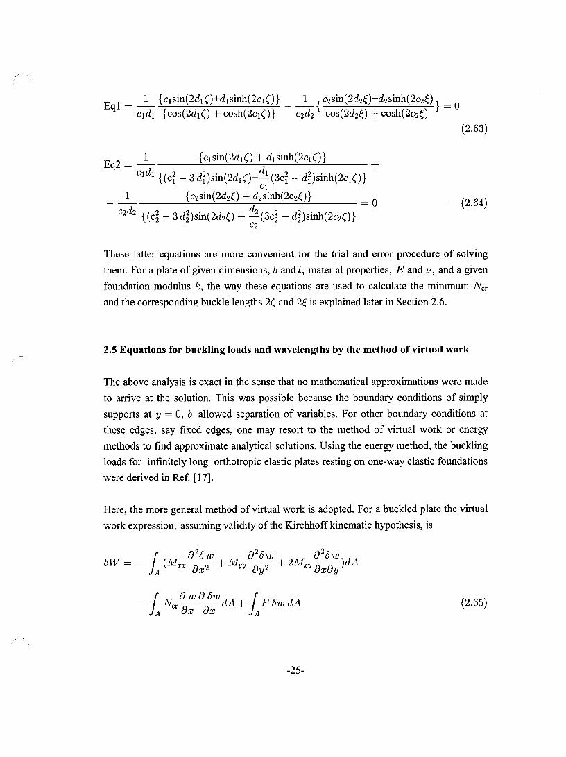
Eql = _1_ {cIsin(2dl()+dlsinh(2cI()} __ 1_{ c2sin(2d2ç)+d2Sinh(2c2ç)} = 0 cldl {cos(2dl() + cosh(2cl()} C2d2 cos(2d2ç) + cosh(2c2Ç)
(2.63)
Eq2 = _1_ {cIsin(2dl() + dlsinh(2cI()} +
Cl dl {(ci _ 3 dDsin(2dl ()+ dl (3ci - dî)sinh(2cI ()} Cl
{C2 sin(2d2ç) + d2sinh(2c2ç)} _ 0
C2 d2 {( c~ - 3 dDsin(2d2ç) + d2 (3c~ - d~)sinh(2c2ç)} -C2
1 (2.64)
These latter equations are more convenient for the trial and error procedure of solving
them. For a plate of given dimensions, b and t, material properties, E and v, and a given
foundation modulus k, the way these equations are used to calculate the minimum Ner
and the corresponding buckle lengths 2( and 2ç is explained later in Section 2.6.
2.5 Equations for buckling loads and wavelengths by the method of virtual work
The above analysis is exact in the sense that no mathematical approximations were made
to arrive at the solution. This was possible because the boundary conditions of simply
supports at y = 0, b allowed separation of variables. For other boundary conditions at
these edges, say fixed edges, one may resort to the method of virtual work or energy
methods to find approximate analytical solutions. Using the energy method, the buckling
loads for infinitely long orthotropic e1astic plates resting on one-way elastic foundations
were derived in Ref. [17].
Here, the more general method of virtual work is adopted. For a buckled plate the virtual
work expression, assuming validity of the Kirchhoffkinematic hypothesis, is
{ 8 w 8 /5w { - J A Ner 8x 8x dA + J A F /5w dA (2.65)
-25-

where wand /5w are respectively the actual and virtual displacements of the plate, Ner is
the buckling load per unit length of the side of the plate, A here denotes the area of the
plate, and F is the foundation reaction force per unit area of the plate.
Let the general relations between stress and strain increments arising due to bifurcation
buckling be written as
(2.66)
where B, C, 15, Fare appropriate moduli at the bifurcation state. These moduli are
assumed constant throughout the plate body. Now, according to Kirchhoffhypothesis, the
strains are related to the displacement derivatives as
(2.67)
which when substituted in the constitutive relations (2.7), give the moment resultants,
upon invoking their definitions, as
The virtual work expression can therefore be written as
(2.69)
where F = k w has been substituted, k being the foundation modulus, which in the
present case of tensionless foundation is allowed to be zero in the no-contact zones. The
assumption is now made that the deflection is the product of two functions,
w(x,y) =~(x)~(y) (2.70)
-26-

where 'Ij;(y) is a suitably chosen known function of y which satisfies the desired boundary
conditions at y = 0, b edges. Then 'Ij;(y) is not subject to any variation, and therefore
8w(x, y) = 8</>(x) 'Ij;(y),
88w = d8</> 'Ij; 88w = 8</> d'lj; 8x dx' 8y dy
(2.71)
With this assumption incorporated, one obtains
(2.72)
Introducing the symbols
(2.73)
the virtual work expression can be written as
(2.74)
The integration is with respect to x, the longitudinal coordinate. Since the end points are
at infinity, one is not interested in the boundary conditions, but only the differential
equation. The latter is obtained as coefficient of 8</>, when integration by parts has
reduced d;~t and d:: to 8</>. The differential equation thus obtained is
-27-

(2.75)
Dividing throughout by J3"iÎJl the above equation can be written in the form
(2.76)
where
(2.77)
This equation is exactly of the same form as the equations (2.16) in the contact zones
when k =1= ° and (2.33) in no-contact zones when k = 0, which has been obtained in the
case of simply supported plates by the equilibrium method, allowing separation of
variables. For the no-contact zone, k = 0, and the coefficients for the differential
equation for 4>2 (X2) are
(2.78)
For linear elastic isotropie materials
_ _ Et3 _ _ _ _ _
B = D = ( 2) = D, C = liB, 2F = D - C 12 1 - 11
(2.79)
The coefficients become
(2.80)
For a simply supported plate 'IjJ(y) = sin 1[; = sin J-LY , where J-L = i, one finds
(2.81)
-28-

(2.82)
Hence, the coefficients in the differential equation become
(2.83)
which then leads to the same differential equations as those obtained by the exact
equilibrium method:
(2.84)
in contact regions, and
(2.85)
in contactless regions for the infinite isotropic plates, simply supported on unloaded
edges.
2.6 Solutions of buckling loads and wavelengths for simply supported plates
The two buckling equations, Eqs. (2.63) and (2.64), obtained by the equilibrium method
for the simply supported plate, are now solved to determine the minimum stress which
would cause buckling. These equations are, however, nonlinear. In each of the two
equations there are three variables, namely the buckling load NeT' the contact area buckle
length 2(, and the no-contact buckle length 2ç. One cannot find a solution for three
unknown variables from two equations. It is necessary to have a third condition. This
condition is supplied by the fact that the buckling load NeT must be a minimum. In the
procedure adopted .here, one assumes a value of 2(, the contact buckle length, and then
finds the other two unknowns from the two buckling equations. This is do ne with
different values of 2( (employing a trial and error procedure) until that value for which
the buckling load NeT has the lowest value. The corresponding variable 2ç, the buckle
length of the no-contact zones, is also then obtained. The Mathematica program for
-29-

doing these calculations can be constructed without much difficulty. The interested reader
may also obtain the author's pro gram by contacting him via the department address.
To incorporate with previous works, particularly Reference [17], the following non
dimensional quantities are introduced:
(2.86)
Thus, NeT is replaced by À, and k is replaced by a. It may be recalled that the buckling
load for an infinitely long simply supported plate, without a foundation, NeT = 4:: D
corresponds to À = 4. Therefore, naturally with a foundation present, À > 4.
As mentioned previously, a Mathematica pro gram was written to solve the buckling
equations. A set of numerical results comprising of À, ( and ~ values were obtained for
the simply supported plate. Table 2.1 lists these values for the tensionless foundation
modulus k varying from 0 to 00.
À
(lb ~/b
Table 2.1 À, ( and ~ for elastic infinitely long simply supported plates
resting on different tensionless foundations
a=O a = 1.0 a = 1000 a = 1.0 x 10⁵ a = 00
4.0 4.332 5.316 5.333 5.333 0.5 0.414 0.075 0.024 0 0.5 0.535 0.759 0.832 0.866
Figure 2-4 provides a graph of À versus a. Also shown on this graph are the results for
the c1amped plate, to be discussed later. The graph shows that as the foundation modulus
increases the buckling load also increases. On the other hand, as shown in Fig. 2-5, the
wavelength of the contact buckles decreases as the modulus increases, Inversely, the
wavelength of no-contact regions increases. When a reaches a large value, (the
foundation is then practically rigid), the bucking load coefficient À reaches its maximum
value of 5.333, the contact wavelength to width ratio (lb approximates 0, and the no
contact wavelength to width ~/b reaches its highest value 0.866. The case (lb = 0
-30-

means that the plate has only line contact and buckles unilaterally, i.e., onlyaway from
the foundation, Fig. 2-6.
The maximum value of À = 5.333, means that the maximum increase in the buckling
load due to a foundation is 33% over that when there is no foundation.
12 i 1
1
10 1
8
....- 1
~ i
1 i
1 1
1 : j
c< 6
4 r
-- 1 ~
-Simply support
1
1
-Clamped support 1 1 1
2
o o 25 50 75 100 125 150 175 200 225
a.
Fig. 2-4 Buckling load coefficient (À) - foundation stiffness parameter (a) curves
with different boundary conditions
-31-

r-'
.,Q -.. ~
0.50
0.45
0.40 1
0.35 1
0.30
0.25
0.20
0.15
1 --
~ i
i
~
0.10 - ""! 1
0.05
o 50 100 150 200 250
Cl
Fig. 2-5 Wavelength to width ratio - foundation stiffness parameter curves
with simply supported unloaded edges
Rigid foundation
Fig. 2-6 Elastic buckling mode ofan infinite plate resting on a rigid foundation [6]
-32-

2.7 Solutions of buckling loads and wavelengths under clamped edges
Following Ref. [17], it is assumed that for an infinitely long plate in x direction and
clamped at the edges y = 0, b, a suitable solution is w(x, y) = 4>(x )sin2( :y) to represent
the deflection of the plate. This choice of '!jJ(y) = sin2 (:y) satisfies the conditions of
deflections and slopes being zero at the longitudinal edges, i.e.,
( 0) - (b)_ow(x,y)1 _ow(x'Y)1 -0 w x, - w x, - oy y=o - oy y=b - (2.87)
. d'!jJ(y) d'!jJ(y) smce '!jJ(O) = '!jJ(b) = ~IY=o = ~Iy=b = 0 (2.88)
The method of virtual work needs to be used to find the buckling load and wavelength
under c1amped boundary conditions. Now, recall that the coefficients in the solution
equations (2.84) and (2.85) are given by
(2.89)
For the function '!jJ(y) = sin2 :y = sin 2f-ty, where f-t = ~, one finds
(2.90)
and hence for a plate of the isotropic elastic material, the above coefficients become
(2.91)
Using these coefficients for determining Cl, dl and C2, d2 for substituting in into Eqs.
(2.63) and (2.64) and carrying out the iterative numerical procedure outlined in Section
2.6, one can arrive at the solution of the critical buckling stresses and the corresponding
wavelengths, see Table 2.2.
The results in Table 2.2 are analogous to the case of simply supported plates. The
buckling loads and the wavelengths vary with the foundation modulus in the same way.
-33-

The buckling load of a long clamped plates with no foundation corresponds to À = 7.285,
When the foundation is rigid the value of the buckling coefficient is maximum,
À = 10.362, which represents an increase of 42%. Variation of the buckling load
coefficient À versus foundation stiffness parameter Œ was shown in Fig. 2-4. The
variation of the wavelength to width ratio (1 b versus foundation stiffness parameter Πis
shown in Fig. 2-7.
It must be realized that whereas the solution for the simply supported plates was exact,
that for the clamped plate is based on an assumed mode shape in the y direction. The
latter is therefore an approximate solution, the goodness of which cannot be ascertained
exactly. However on physical grounds, the results should be accurate enough, since the
assumed mode shape is quite realistic.
À
(lb çlb
Table 2.2 À, ( and ç for elastic infinitely long, clamped plates
resting on different tensionless foundations
Œ=O Œ = 1.0 Œ = 1000 Œ = 1.0 X 10⁵
7.285 7.483 10.229 10.362 0.5 0.320 0.075 0.024 0.5 0.339 0.467 0.536
-34-
Π= 00
10.362 0
0.570

,.Q ........ ~
0.50 :
:
0.45 :
0.40 .. _-i
1
0.35 1 1
_._~~
0.30
0.25
0.20
0.15
i
\ ! i
i
"' """" 0.10 - 1 0.05 i
o 50 100 150 200 250
Fig. 2-7 Wavelength to width ratio - foundation stiffness parameter curves
with clamped unloaded edges
-35-

~
!
Chapter 3
Plastic Buckling of Infinitely Long Plates Resting on Elastic Foundations
This chapter is concemed with the plastic buckling of infinitely long plates on elastic
foundations. The main difference with the preceding chapter is that now the material
moduli are those for an elastic-plastic, strain-hardening material. Aluminum is a typical
example of such material, and also sorne types of steel which do not exhibit a yield
plateau like mild steel, but have a rising strain-hardening behaviour. The kinematic
assumptions made here are identical to those in the previous chapter. Hence the equations
of equilibrium are identical, and so is the virtual work expression.
3.1 Constitutive relations of the plasticity theories
The following discussion is elementary and restricted to the purpose of this thesis. The
reader may consult standard books on the theory ofplasticity, notably the one by Hill [21]
for detailed discussions and explanations.
The constitutive relations needed here for the present bifurcation analyses are of the
incremental type. Given a present state of deformation, with stresses {aO} and strains
{éO}, they relate the increments in stresses {da }to the increments in strains {dé}, i.e.,
{da }=[D]{ dt} (3.1)
where [D] is the matrix of elastic/plastic moduli. The matrix [D] incorporates the
postulated plastic behaviour of the material, and generally depends on the existing
stresses {aO} and strains {éO}. There are two competing theories of plasticity which are
simple, and therefore most often used. They are called the J2 incremental and J2
deformation theories of plasticity. They both incorporate the following observed and
experimentally corroborated behaviour of metals. First, they satisfy the condition of zero
plastic volume change in recognition of the fact that, for metals, plasticity arises due to
-36-

slip displacements of metal crystals over slip planes. Secondly, they obey the von Mises,
or alternatively, the J2 yield condition:
O"e = /3.h. = O"~(cp) (3.2)
This condition says that, potentially, a plastic deformation is possible if the CUITent stress
point, typified by 0" e = /3.h. for a general state of stress, lies on the CUITent yield
surface. 0" e is called the von Mises equivalent stress. This yield surface depends on the
total plastic strain cp accumulated during previous history of plastic straining. The yield
surface expands uniformly in the stress space with increasing cp. This behaviour, valid
for small strains, is called isotropie hardening. An increment of stress when the stress
point (before the increment) is situated on the yield surface will result in dO"e = 32
dJ2• If
O"e then, dJ2 > ° there is loading, i.e. there is further plastic deformation. If dJ2 = 0, there
is neutral loading in the sense that although no plastic deformation takes place, the
material remains in the yield state by virtue of the fact that the stress point is still on the
yield surface, and there is possibility of plastic increments of strain for a second
increment of stress. When however, dJ2 < 0, there is unloading. The stress point is no
longer on the yield surface (it has come inside) and small enough increments of stresses
will only pro duce elastic strains.
The incremental theory postulates relations between the deviatoric stress O"kk 8 d hl· .. Th 1· .. Sij = O"ij - 3 ij an tep astIc stram mcrements. e e astIc stram mcrements are
related to the stress increments by the standard elastic law for plates. Thus,
(3.3)
where, h is the hardening parameter related to the position of the stress point on the
uniaxial stress-strain curve of the material, and [ CE 1 is the standard compliance matrix for
linear isotropie elastic behaviour. Under the small strain assumption, the total strain
increments are taken to be the sum of the elastic and plastic parts. The combined relations
may be expressed as
{ dE} = [Cd { dO" }, or by inverting them as {dO"} = [Dt]{ dE } (3.4)
-37-

where [Ct] denotes the incremental compliance matrix, and [Dt] stands for the
incremental moduli matrix. It is the inverted form which is needed in the further
deve10pment of the theory.
The deformation theory postulates relations between the deviatoric stress
Sij = (J"ij - (J"~k Oij and the total plastic strains. The elastic strains are related to the stress
by the standard elastic law for plates. Thus,
(3.5)
where now <p is the hardening parameter related to the position of the stress point on the
uniaxial stress-strain curve of the material, and [CE] is the same matrix as earlier. The
total strains are taken to be the sum of the elastic and plastic parts. The combined
relations may be expressed as
{E} = [CsH (J"}, or by inverting them as {(J"} = [DsH E} (3.6)
where [Cs] denotes the elastic/plastic compliance matrix, and [Ds] is the inverse of [Cs] and may be called the matrix of the secant moduli.
The difference between the incremental theory and the deformation theory is now c1ear.
While the former provides a relation between stress and strain increments, the latter
postulates a relation between the total quantities. The deformatian theory is therefore like
a nonlinear elasticity theory with stress dependent moduli. The incremental theory on the
other hand is history dependent and employs the notion of loading and unloading. The
two theories however become identical if the loading is proportional in that d(J"ij = Π(J"ij.
Based on experimental and theoretical considerations, the incremental theory is
considered a correct theory of plasticity. However, its application is more difficult.
Therefore, despite its weak foundations the deformation theory continues to be used
because of its relative simplicity. Moreover, for bifurcation problems, especially of plane
plates, the bifurcation loads predicted by the incremental theory are sometimes absurdly
higher than the experimental values. Paradoxically, the bifurcation loads predicted by the
deformation theory for plane plates are in good and conservative agreement with the test
results, and also invariably lower than the bifurcation loads from the incremental theory
[22]. Therefore from a practical point of view it is the deformation theory buckling loads
-38-

which should be used, like in the present work. The incremental theOly is known to be
very imperfection sensitive, and hence the maximum loads computed by the incremental
theory can be made to agree with the experimentalloads if a realistic imperfection growth
analysis can be carried out. However, this latter procedure is time consuming, and gives
uncertain answers depending upon the amplitudes of the imperfections, and is usually not
recommended.
3.2 Constitutive relations for a plastic bifurcation analysis
Now, for a bifurcation analysis, one needs incremental relations, even for the deformation
theory. In buckling of the axially stressed plates, the state of stress changes suddenly from
a uniaxial one to a multiaxial state, with increments in stress and strain occurring in other
directions due to buckling. The needed incremental relations for the deformation theory
are obtained by differentiating the total relations indicated above. Without further going
into details, it can be said that the applicable stress strain relations can be expressed as
[10,25]
{ dO"} = [Dl{ dE} or explicitly as
dO"xx = B'dExx + C'dEyy , dO"yy = C'dExx + D'dEyy , dO"xy = 2F' dExy (3.7)
where it can be shown that
B' = E( g+ 3e + 3) g(5 + 3e - 411) - (1- 211)2
C' = 2E (g - 1 + 211) g(5 + 3e - 411) - (1- 211)2
D'- 4g - g(5 + 3e - 411) - (1- 211)2
F,= __ E __ _ 2 + 211 + 3e
(3.8)
and where in the above
-39-

E E e=--l g=-
Es ' Et (3.9)
These two parameters e and gare found from the uniaxial stress strain curve of the
material at the stress level equal to the applied axial stress. Es is the secant modulus at
this level, and Et is the corresponding tangent modulus.
The above relations, valid for the deformation theory, can be specialized to those for the
incremental theory by putting e = 0 in the above definitions of the moduli. Furthermore,
putting g = 1, and e = 0 results in the relations for the elastic behaviour.
It is now convenient to change the notation slightly. From now on, the increments in
strain and stress due to buckling will be denoted by Exx, Eyy. Exy and (}'xx, (}'yy. (}'xy. Thus,
the above relations will read as
(}' xx = B' Exx + C'Eyy , (}' yy = C' fxx + D'Eyy , (}' xy = 2 F' Exy (3.10)
with exactly the same meaning for the moduli as above.
One may now recall the Kirchhoff kinematic hypothesis to connect the buckling strains to
buckling deflection w(x, y) as
Exx = (3.11)
In accordance with Shanley's concept of plastic bifurcation occurring under increasing
load [23, 24], so that the plastic strains increase over the entire thickness of the plate, the
moduli are those of loading, and hence the stresses are
The moment stress resultants due to buckling are then
Mxx = l t/2
z(}'xxdz = _ ~ (B' 82~ + C' 82~) -t/2 12 8x 8y
-40-
_ 2zF' 82w
ox8y (3.12)

jt/2
Myy = z CYyydz = -t/2
_ f (C' Ô2
W + D' Ô2W)
12 ôx2 ôy2
M xy = jt/2 zCYxydz = _ f(2pl ô2w )
-t/2 12 ôxôy
(3.13)
3.3 Equations for buckling loads and wavelengths by the equilibrium method
A procedure similar to the elastic case is now followed to derive the exact buckling
conditions for a plate simply supported along the longitudinal edges, y = 0, b.
The applicable equilibrium equations, independent of the material behaviour, are
(3.14)
in the contact zones, and
(3.15)
in the no-contact zones.
Substitution of the expressions in terms of the curvatures transforms (3.14) and (3.15) to
(3.16)
and
(3.17)
-41-
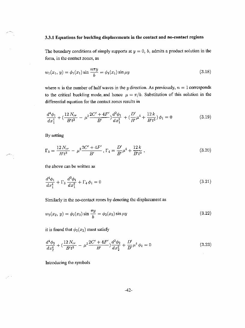
3.3.1 Equations for buckling displacements in the contact and no-contact regions
The boundary conditions of S'imply supports at y = 0, b, admits a product solution in the
form, in the contact zones, as
(3.18)
where n is the number of half waves in the y direction. As previously, n = 1 corresponds
to the critical buckling mode, and hence J-t = 7r lb. Substitution of this solution in the
differential equation for the contact zones results in
(3.19)
By setting
f _ 12 NeT' 2C' + 4F' D' 12 k 3 - B't3 - J-t2 B' ,f4 = B,J-t4 + B't3 ' (3.20)
the above can be written as
(3.21)
Similarly in the no-contact zones by denoting the displacement as
(3.22)
it is found that <P2(X2) must satisfy
d4cp2 ( 12 NeT' _ 2 2C' + 4F') d2cp2 D' 4 A. _ 0 dx~ + B't3 J-t B' dx~ + B' J-t 'f'2-
(3.23)
Introducing the symbols
-42-

r' - r - 12 N er _ 2 2C' + 4F' d r' _ D' 4 3 - 3 - B
't3 IL B' ' an 4 - B' IL (3.24)
the above equation can be written as
(3.25)
3.3.2 Derivation of the buckling equations
The solution fOTIn of the functions <Pl (Xl) is exactly the same as that obtained for the
elastic case, namely
except that Cl and dl are obtained from the present definitions of r 3 and r 4 for the plastic
case (rather than ri and r 2 of the elastic case).
Likewise, for the no-contact zone <P2 (X2) is of the same as in the elastic case, namely
except that C2 and d2 are obtained from the present detinitions of r~ and r~for the plastic
case.
As mentioned in Section 2.3 as weIl as 2.4, previously, the product solution ensures that
the matching conditions remain the same, which at the common edges of the contact and
no-contact zones require equality of the functions to zero, and equality of the tirst,
second, and third derivatives. The two buckling equations are of the same fOTIn as for the
e1astic case, repeated here for convenience
Eql = _1_ {cIsin(2dl()+dlsinh(2cI()} __ 1_{c2sin(2d2ç)+d2sinh(2c2ç)} = 0 cldl {cos(2dl() + cosh(2cl()} C2d2 cos(2d2ç) + cosh(2c2ç)
(2.63)
-43-

(2.64)
Therefore, the method of solving Eqs. (2.63) and (2.64) explained previously in Chapter 2
can also be applied to the plastic buckling equations. However, in solving these
equations, one must remember that the moduli to be used here are stress dependent (and
not constants as was the case with elastic buckling).
3.4 Equations for buckling loads and wavelengths by the method of virtual work
There is no need to repeat the virtual work method introduced in the last Chapter. The
method was developed using a general form of the constitutive relations with 13, C, D, and Fas symbols for the moduli. Here these moduli are identified as the elastic-plastic
moduli B', C', D', F' defined by Eq. (3.8).
The forms of the deflections are taken as
(3.26)
(3.27)
Thus leads to the differential equation for the contact zones
(3.28)
where
(3.29)
-44-

and the equation for the no-contact zones
(3.30)
where
(3.31)
For a plate clamped on the edges y = 0, b, the mode form 'lj;(y) satisfying the condition
of zero deflections and zero slopes is assumed to be the same as for the elastic case, as
(3.32)
from the equation (2.73), one then finds
(2.81)
And hence for a plate of the isotropic elastic material, the above coefficients become
(3.33)
The form of the solution functions 4>1 (Xl) and 4>2(X2) is the same in Section 2.5. The
matching conditions also remain unchanged. Rence the forms of the two buckling
equations are the same as Eqs. (2.63) and (2.64) except that the moduli are stress
dependent, and the quantities Cl, dl, C2, d2 have to be found from the present definition - - -/ -/
of r 3 , r 4, r 3' r 4.
3.5 Buckling loads and wavelengths for simply supported plates
The plastic buckling problem is a bit more complicated than the elastic one. The reason is
that the tangent and secant moduli required in the calculations are dependent on the
stress-strain curve of the plate material, and on the critical stress at which these moduli
-45-

must be computed. Therefore, a part of the input data is the uniaxial stress-strain curve.
Here, as an example, the plate material is taken as an Aluminum alloy, 24S-T3. For this
alloy one has E = 76,535 MPa, 11 = 0.32, and the 0.2% proof stress (equivalent to the
yield stress) O"y = 300 MPa. The following Ramberg-Osgood function is suitable [25, 26]
for expressing strain as a function of stress:
0" cr 002 ( 0" cr )7 E = 76 535 + o. 300 , (3.34)
The E - 0" graph ofthis function is shown in Fig. 3-1.
550
500 ,-.., ro
450 ~
~ 400 rI:)~
ri:)
350 CI)
.l:::J r/.l 300
~ """..,.. -
V ~ V 1
gf 250 ..... ...... .!>d 200 u
;:::s /
-~ t---1
o:l 150 '-' J,o 100 CJ
~ --
b 50
0
o 5 10 15 20 25 30 35 40 45 50 55 60 65 70 75 80 85
ê (Strain, 1 0-3)
Fig. 3-1 Uniaxial stress-strain curve for Aluminum alloy 24S - T3
By using Eqs. (2.63) and (2.64) through the Mathematica software and employing both
the deformation and the incremental theories, one finds a set ofresults of À, (/b and t;,/b for an infinitely long plate simply supported on longitudinal edges, resting on a one-way
elastic foundation, and loaded by uniform compressive force in x direction. The results
are mathematically exact unlike those for the c1amped plate (to be discussed shortly)
-46-

which are based on an assumed but reasonable mode shape. These results are shown in
Table 3.1 for the deformation theory, and in Table 3.2 for the incremental theory.
Table 3.1 À, ( and ç- for an infinitely long simply supported Al alloy 24S - T3 plate
resting on elastic one-way foundations with different foundation parameter Œ
(bit = 25, Deformation theory)
Œ=O Œ = 1.0 Œ = 1000 Œ = 1.0 X 10⁵ Œ = 00
À 2.602 2.672 2.797 2.798 2.798 (lb 0.5 0.320 0.056 0.018 0 Ç-Ib 0.5 0.446 0.639 0.693 0.707
Table 3.2 À, ( and ç- for an infinitely long, simply supported Al alloy 24S - T3 plate
resting on elastic one-way foundations with different foundation parameter Œ
(bit = 25, IncrementaI theory)
Œ=O Œ = 1.0 Œ = 1000 Œ = 1.0 X 10⁵ Œ = 00
À 3.363 3.524 3.978 3.986 3.986 (lb 0.5 0.290 0.054 0.017 0 Ç-Ib 0.5 0.379 0.548 0.599 0.615
These results show that the plate indeed buckles in the plastic range. For Π= 0, i.e., with
no foundations, the buckling loads from the present theory are equal to the ones
calculated by Bijlaard [10]. As usual, the bifurcation buckling loads from the incremental
theory are significantly higher than the ones predicted by the deformation theory. Also,
the buckling loads are affected by the width to thickness bit ratio. Relatively stockier
plates with smaller bit will undergo plastic buckling.
As expected, the buckling load increases and the contact length decreases with the
increase in the foundation modulus. However, the maximum increase in the buckling load
is limited to 7.5% for the deformation the ory, and 18.5% for the incremental theory. Fig.
3-2 shows the effect of the increase in foundation modulus on the buckling load for the
above plate. It is c1ear from this figure that the maximum increase in buckling load can be
realized by relatively soft foundations.
-47-

The contact length decreases with the increase in the foundation modulus, as shown in
Fig. 3-3 for the deformation theory and in Fig. 3-4 for the incremental theory. Evidently
the contact length diminishes rapidly as the foundation modulus is increased. The contact
length is about 10% of the width for a considerable range (50-200) of the foundation
parameter.
6 !
i 1
1
1
i -----_._-1---1
5
4 r-I 1
~ 3 : 1
: 1
1
---- -------- -------2
-"-Deformation Theory -
: -IncrementaI Theory 1
1 ! ! ! ! o o 25 50 75 100 125 150 175 200 225
Cl
Fig. 3-2 Plastic buckling parameter ,\ vs. foundation stiffness Cl( for simply supported plates
-48-

r"-~
,.Q
---~
,.Q
).JI
0.50
0.45
0.40
0.35 •
0.30
0.25
0.20
0.15
0.10
0.05
0.00
0 50 100 150 200
Fig. 3-3 Contact length /plate-width vs. foundation stiffness
for simply supported plates; Deformation theory results
0.50 1 1
1
0.45 ! . 1
0.40
0.35 i
0.30 1 1 :
0.25
0.20
0.15
0.10
0.05
0.00
\. ., 1
i
1
i 1
,
1
o 50 100 150 200
Fig. 3-4 Contact length /plate-width vs. foundation stiffness
for simply supported plates; IncrementaI theory results
-49-
250
250

3.6 Buckling loads and wavelengths for c1amped plates
The plate in this section is c1amped along its longitudinal edges and resting on a one-way
elastic foundation. Hence equations (2.63) and (2.64) corresponding to the method of
virtual work need to be used to obtain the minimum buckling loads and wavelengths. The
solution is semi-exact since a reasonable mode shape was assumed in the longitudinal
direction to effect the separation of variables. Mathematically, it is not possible to say
how good are the results, but physically we may compare them with experiments. The
plate material is Aluminum alloy 24S - T3, with a uniaxial stress-strain curve shown
previously (Fig. 3-1).
Following the same procedure as in the last section, one obtains a series of results for À,
(lb and f,lb as functions of the foundation stiffness parameter a. These results are
determined for both the deformation and the incremental theories. Table 3.3 shows sorne
ofthese results for the deformation theory, whereas Table 3.4 gives the parallel results for
the incremental theory.
Table 3.3 À, (, f, for an infinitely long, c1amped Al alloy 24S-T3 plate resting on one-way
elastic foundations for different foundation parameter a (bit = 25, Deformation theory)
a=O a = 1.0 a = 1000 a = 1.0 x 10⁵ a = 00
À 3.033 3.062 3.238 3.242 3.242 (lb 0.5 0.240 0.049 0.015 0 çlb 0.5 0.270 0.389 0.433 0.451
Table 3.4 À, (, f, for an infinitely long, c1amped Al alloy 24S-T3 plate resting on one-way
elastic foundations for different foundation parameter a (bit = 25, Incrementai theory)
a=O a = 1.0 a = 1000 a = 1.0 x 10⁵ a = 00
À 5.342 5.440 6.757 8.892 8.897 (lb 0.5 0.220 0.053 0.017 0 f,lb 0.5 0.235 0.330 0.497 0.517
-50-

For the deformation theory the maximum increase in the buckling parameter À for this
plate (bit - 25) is less than 7%. For the incremental theory it is more than 66%. These
increases in À versus foundation parameter Œ are seen more c1early in Fig. 3-5. The
predictions are quite insensitive to stiffness parameter Π> 25 for the deformation theory
and Π> 100 for the incremental theory
Fig. 3-6 and 3-7 express the variation of the contact length versus the foundation
parameter Œ. The contact length decreases rapidly first as the foundation modulus is
increased, but settles down to about 10% of the platewidth at Π= 75.
7.0 6.5 6.0 5.5 5.0 4.5 4.0 3.5 3.0 2.5 2.0 1.5 1.0 0.5 0.0
1
JIIA -- i ;'
1
~--- --_._- -~- -------
i
! ---
: 1
i ,
---- 1 - Deformation Theory -,
i
1 - IncrementaI Theory -
i 1 1 1 1 "1
o 25 50 75 100 125150175200 225250
Fig. 3-5 Plastic buckling parameter À vs. foundation stiffness Œ for c1amped plates
-51-

0.50 0.45 0.40 0.35 0.30
,.Q 0.25 --~ 0.20 0.15 0.10 0.05 0.00
0.50 0.45 0040 0.35
,.Q 0.30
-- 0.25 U"
0.20 0.15 0.10 0.05 0.00
0 25 50 75 100 125 150 175 200 225 250
Fig. 3-6 Contact length /plate-width vs. foundation stiffness
for clamped plates; Deformation theory results
~ --
"'-r-
o 25 50 75 100 125 150 175 200 225 250
Fig. 3-7 Contact length /plate-width vs. foundation stiffness
for clamped plates; IncrementaI theory results
-52-

Chapter 4
Application to Concrete-filled Steel Box Columns, and Verifications with Experiments
This chapter presents applications as weIl as verifications of the theoretical buckling
analyses of the preceding chapter. First, the present theory is employed for calculating
the ultimate loads of concrete-filled steel box columns. Then, these theoretical results are
verified against available experimental results of other researchers, namely those of
Dalin Liu [1] and of Brain Uy, Q. and Q. Liang [5, 6]. Comparison of the theoretical
results is also made with the values obtained by using empirical equations of the CUITent
design codes of different countries.
4.1 Application to concrete-filled steel box columns
Concrete-filled steel box columns, of square or rectangular shapes, are being used
extensively in multi-storey building construction throughout the world [l, 5, 18]. These
columns are formed by pouring concrete into fabricated steel-box columns after they have
been secured and positioned on site. They are more cost-effective than bare (unfiIled)
steel columns as weIl as reinforced concrete columns. The behaviour of the concrete
filled steel box columns is influenced by deformation ofboth steel and encased concrete.
Numerous experiments conducted in recent years have revealed that typical failure modes
of concrete-filled columns are buckling in steel sections and crushing in concrete, see Fig.
4-1. Based on the present theory, the buckling of a steel section is identified with the
buckling of the steel plates of the box section, taking into consideration the constraining
influence of the in-filled concrete. Consequently, the ultimate strength for concrete-filled
box columns is calculated from the buckling load of steel plates, and the maximum
capacity in compression of the concrete core. The combined failure load, based upon
simultaneous buckling of steel box column plates and crushing of concrete, is expressed
as
(4.1)
-53-

in which, N s = acrAs, is the buckling load of steel box sections, and Ne = 0.85 f~Ac is
the maximum concrete capacity in compression. acr denotes the critical buckling stress of
steel plates unilaterally constrained by the in-filled concrete. The foundation modulus k
(also called the normal stiffness) of concrete is generally taken [5] as 23 GPa. This value
corresponds to an a around 500, 000 (depending on bit ratio of the column section). For
rectangular columns, the applicable width-to-thickness ratio is the larger one, i.e., bit as
shown in Fig. 4-2. The plates with larger width will buckle first and the corresponding
bit must be used in the formulas to calculate the buckling stress a cr. As is the area of
steel section, As = 4bt for square sections and As = 2bt + 2ht for rectangular sections.
f~ is the strength of test cylinders and Ac equals to the area of the concrete section. The
modification factor 0.85 is used to account for the uncertainty between the concrete
strength in laboratory and in situ. In the above formula, although the influence of concrete
confinement on the steel plates has been accounted for, the confinement effect of steel on
the encased concrete is not. This latter effect in a concrete-filled rectangular columns is
limited to the corners of the section and is small enough to be omitted [5].
(a) (b) (c)
Fig. 4-1 Typical failure modes of concrete-filled box columns [1]
-54-

b ~I ..0lIl ..
b
..0lIl .. b
h
"I11III " ,.
"I11III --'" ,..
"" Steel Plate "" Steel Plate
(a) Rectangular Plate (b) Square Plate
Fig. 4-2 Sections of steel box columns
Determination of a cr in Equation (4.1) is the most important step to calculate the ultimate
strength of concrete-filled steel box columns. For determining acr , the properties of steel
should be ascertained, especially the stress-strain curve in the elastic as well plastic
ranges. This stress-strain curve is usually obtained from coupon tests of the steel of the
box sections. This curve is then modeled approximately by an analytical expression,
expressing strain as a function of stress, E = E ( a ). In the present work, the stress-strain
curves are modeled by adopting the well-known Ramburg-Osgood representation [26].
The applicable boundary conditions at the edges of plates, for an un-filled section are
taken as simply supported. However, for plates of the concrete-filled sections, the
appropriate conditions are those for clamped plates. These assumptions, as depicted in
Fig. 4-3, model the actual conditions quite closely.
Although analytical results were presented for both the J2 incremental and J2 deformation
theories of plasticity, it was found (and it is weIl known for bare plates) that the
bifurcation stress predicted on the basis of the incremental theory is too high compared
with the experimental values. On the other hand, the bifurcation stress calculated from the
deformation theory matches quite well with experiments, and in fact provides slightly
-55-

conservative (i.e., safe) predictions. Therefore as a practical option, the theoretical results
of only the deformation theory will be used in this chapter. This is quite acceptable as the
deformation theory has been in wide use in engineering practice.
\
1 ,
\ \ , 1
1
(a) Concrete-filled steel box columns
"",., .... - .............. .... ....
,; ...
~
\ 1
1 \ , \ , ,
\ 1 \
1 \ 1 \
. .... ,-......... ,.'" ... _ ......
(b) Hollow steel box columns
Fig. 4-3 Buckling modes of steel box columns
In reality, the length of the column is generally much greater than its width. Thus, the
plates making up the box column can be considered to be "infinitely" long to fulfill the
conditions of the present theory. It is well-known [27] that the buckling load of a plate is
not affected by its aspect ratio (length a to width b ratio) if it is greater than 4. In this
connection, it is worthwhile to mention the work of Shahwan [4], in which he showed
that for axially compressed elastic plates attached to an elastic (Winkler) foundation, their
buckling loads varied little with plate's aspect ratio, after it is larger than even one. Figure
4-4, taken from Ref. [4] makes this point very clearly. The graph shows variation of the
elastic buckling stress with the aspect ratio, It can be observed that the higher the
foundation modulus, the less is the deviation of the buckling stress with that at aspect
ratio of unity. The above conclusion is extended here to the plastic buckling of
unilaterally constrained plates. Thus, the theory developed for infinitely long plates is
suitable for the practical cases of plates of finite lengths.
-56-

16,-ï----------------------------------------,
12 - ex = 20
--'---1
4 0.=2
~._-------_ .. a=O
O;--------.--------r-------,--------.------~ o 2 " 5
a/b
Fig. 4-4 Buckling load coefficient .ÀCT vs. aspect ratio ajb for simply supported isotropic
elastic plates fixed to a foundation of stiffness a [4]
4.2 Verification with experiments
As mentioned before, there are a number of experiments that have been reported in the
literature on the strength of concrete-filled steel box columns. These tests employed both
the normal strength and high strength steels. Here the theoretical results are compared
with the results of the tests which were conducted by Q. Q. Liang et al. [5], Brain Uy [6]
and Dalin Liu et al. [1]. These experiments cover a variety of steel and con crete types,
and columns with filled as weIl as ho119w sections, square sections, and rectangular
sections.
According to the test data reported by Liang and Uy [5], the stress-strain curve of the steel
used by them was approximated by the author as a Ramberg-Osgood curve by the
following equation [25]:
(4.2)
-57-

/~-.
The graphical representation ofthis equation is shown in Fig. 4-5.
400 1
i
350 !
i
1
; !
300 r-I
i
!
,--.., 250 C';$ p.,
::s 200 ,
1
i '-"
1
t:> 150 ~ -
100 1
50
0
i 1 1
1
1
i
i
0.00 0.02 0.04 0.06 0.08 0.10 0.12 0.14 0.16 0.18
e
Fig. 4-5 Ramberg- Osgood curve of steel (O"y = 281MPa) used in the experiments
conducted by Liang and Uy [5]
Similarly, the Ramberg-Osgood curves were derived for the experiments conducted by
Uy [6], and by Dalin Liu et al. [1] respectively. The curve for the former series of tests
[6] was found to be
€ = EO" + 0.002 ( !!.- )34 O"y
and for the latter ones [1] as
€ = EO" + 0.002 ( !!.- )46 O"y
The graphs of these equations are shown in Fig. 4-6 and 4-7 respectively.
-58-
(4.3)
(4.4)

f~'·,
//--.
900 1 1
1
800
700
600 -. ~ 500 p.,
:E '-' 400 t:>
300
200
100
0
i 1
1
: 1
,
t7' 1 !
~ /' 1 j
: 1
1
1 1
I---~ ,1 i
~-
1
i
! --Coupon Test
~ .~-----
- Ramberg-Osgood Curve -
!
i i 1 1 1 1 1 1
o 2 4 6 8 10 12 14 16 18 20 22
e (m e)
Fig. 4-6 Ramberg-Osgood curve for steel used in the experiment conducted by Uy [6]
,-..., cd ~ ::;E "-' t>
700
600 ~
~ ,.--500
400
300
200 ~
100
0
--Coupon Test 1
~
1 - Ramberg-Osgood Curve !
1 1 1 1 1
0.00 0.03 0.06 0.09 0.12 0.15 0.18 0.21 0.24 0.27
e
Fig. 4-7 Ramberg-Osgood curve for steel used in the experiment conducted
by D. Liu et al. [1]
-59-

Using the respective Ramberg-Osgood representations, one can determine the secant and
tangent moduli as functions of the axial stress. These moduli are needed in the buckling
equations of Chapter 3, to determine the buckling stress according to the deformation
theory of plasticity. Formula (4.1) can then be used to obtain the theoreticaUy predicted
failure load for the individual specimen of each experiments mentioned above. The
comparisons between the present theory and each experiment are shown in Table 4.1-4.5.
For the study [5], with data tabulated in Table 4.1, there are six specimens for which aU
sections are square. The strengths of both the steel and concrete are normal (not high
strength). It is found that the results of the presented theory are little lower (i.e., on safe
side) than the experimental results, and the differences lie in the range of 0.1 % to 12%
with an average of 4%. There are three specimens showing nearly the same values
between the predictions and tests. Thus, the present theoretical results are in better
agreement with the test results than those computed by other researchers by using the
finite strip method of analysis; their results are lower than the test results from 2% to 18%
with the average of 8%.
The agreement with test results is even better for the experiment reported in [6], see Table
4.2. For 8 specimens, there is a mean difference of only 1 % from the experimental results,
and three of them are almost the same as the experiments. The exceptions, are the
specimens HSS14 and HSS15. The differences for them are quite out of line, which
suggests a discrepancy in the reported data. The distinct characteristic in this set of test is
that the steel is of the high strength variety. Hence, the comparisons for the cases in [5]
and [6] show that the present theory can be used for both high and low strength steel box
columns.
For the experiments reported in [1], comparison is made for up to 10 specimens, not only
between the theoretical and experimental results but also with the values obtained by
using the equations of the design codes of different countries, as shown in Table 4.3 and
Table 4.4. The present theoretical results are aU on the safe side (i.e. below the
experimental values), and can be seen to be more accurate than those calculated by the
design formulas of AISC and AC!. However, the results from the equations of EC4
compare quite weU with the experiments. In comparison with the test results, the mean
values of the calculated results are lower by about 10%, 15%, 14% and 9% for the present
theoretical prediction, AISC, ACI, and EC4, respectively. Thus, the results from EC4
appear a little better than the present theory for this series of tests. However, one should
-60-

keep in mind the limitation of the EC4 equations. The EC4 formulas are applicable only
to the cases where concrete and steel strengths are not greater than 40 MPa and 355 MPa
respectively. Renee, in fact, EC4 formulas should not be employed for this series of
experiments to predict the column capacities, because the strengths of both the concrete
and the steel are over the stipulated limitations. In these experiments, the steel and
concrete are both of high strength, and thus the point can be made that the present
theoretical predictions for concrete-filled steel box columns are applicable for the various
classes of strengths of steel and con crete used in construction.
The scatter of the present predictions versus each set of experiments are shown in Figs.
4-8,4-9, and 4-10. Fig. 4-10 also contains scatters for predictions from the various design
equations. The conclusion evident from these figures is that the present theoretical
predictions are mostly below the experimental values, but not overly conservative.
-61-

Table 4.1 Comparison of the present theoretical predictions NT with experiments [5]
1 2 3 4 5 6 7 8 9 10 11 Specimen bxh bit O"y f~ O"cr Nu NT Nt Nr/Nu Nt/Nu
NSI 180 x 180 60 294 33.6 291.1 1555 1554 1428.6 0.999 0.919 NS7 240 x 240 80 292 40.6 259.2 3095 2734 2548.8 0.883 0.824 NS13 300 x 300 100 281 44 187.3 4003 4040 3953.3 1.009 0.988 NSl4 300 x 300 100 281 47 187.3 4253 4270 4182.8 1.003 0.983 NSl5 300 x 300 100 281 47 187.3 4495 4270 4182.8 0.950 0.931 NSl6 300 x 300 100 281 47 187.3 4658 4270 4182.8 0.917 0.898 Mean 0.960 0.924
Note: that the elastic modulus of steel is E = 200 GPa; b, h = widths of steel sheet in each
direction (mm), t- thickness of steel sheet (3 mm), O"y = yielding stress of steel (MPa), f~ =
ultimate strength of concrete cylinder test (MPa), O"cr = buckling load of steel plate (MPa), Nu
= ultimate testing load of specimens (kN), NT = ultimate predicted load by the present theory
(kN), Nt = ultimate load predicted by Q. Q. Liang (kN).
Table 4.2 Comparison of the present theoretical predictions NT with experiments [6]
1 2 3 4 5 6 7 8 9 Specimen bxh bit O"y f~ O"cr Nu NT Nr/Nu HSSHI 100 x 100 20 750 NA 774.0 1644 1548 0.942 HSSH2 100 x 100 20 750 NA 774.0 1561 1548 0.992 HSSI 100 x 100 20 750 28 793.8 1836 1826 0.994 HSS2 100 x 100 20 750 28 793.8 1832 1826 0.997 HSS8 150 x 150 30 750 30 763.9 2868 2865 0.999 HSS9 150 x 150 30 750 30 763.9 2922 2865 0.980
HSS14 200 x 200 40 750 32 727.9 3710 4000 1.078 HSS15 200 x 200 40 750 32 727.9 3483 4000 1.148 Mean 1.016
Note: the Young's modulus of steel is 200 GPa; the symbols are same as in Table 4.1;
the specimens ofHSSHl and HSSH2 are hollow section steel columns without
concrete core.
-62-

Table 4.3 Geometrie and material properties of test specimens [1]
1 2 3 4 5 6 7 8 Specimen B x H(mm) b x h(mm) t(mm) bit E(OPa) ay(MPa) f~(MPa)
CI-I 100.3 x 98.2 91.4 x 89.8 4.18 22 207 550 70.8 CI-2 101.5 x 100.6 93.1 x 92.2 4.18 22 207 550 70.8 C2-1 101.2 x 101.1 92.8 x 92.7 4.18 22 207 550 82.1 C2-2 100.7 x 100.4 92.3 x 92.0 4.18 22 207 550 82.1 C3 182.8 x 181.2 174.4 x 172.8 4.18 42 207 550 70.8 C4 181.8 x 180.4 173.4 x 172.0 4.18 42 207 550 82.1
C5-1 120.7 x 80.1 112.3 x 71.7 4.18 27 207 550 70.8 C5-2 119.3 x 80.6 110.9 x 72.2 4.18 27 207 550 70.8 C6-1 119.6 x 80.6 111.2 x 72.2 4.18 27 207 550 82.1 C6-2 120.5 x 80.6 112.1 x 72.2 4.18 27 207 550 82.1
Note: B x H = the dimension of section of columns, b x h = the dimension of section of
concrete cores and widths of steel sheet in each direction; the other symbols have the same
meaning as in Tables 4.1, 4.2.
1 Specimen
CI-I CI-2 C2-1 C2-2 C3 C4
C5-1 C5-2 C6-1 C6-2 Mean
Table 4.4 Comparison of the present theoretical predictions NI'
with experimental results [1], EC 4, AISC, and ACI
2 3 4 5 6 7 8 9 10 acr Nu NT NE NA NI Nr/Nu NE/Nu NA/Nu
572.0 1490 1366 1376 1291 1301 0.917 0.923 0.867 572.0 1535 1403 1413 1325 1335 0.914 0.921 0.863 572.0 1740 1488 1513 1409 1419 0.855 0.870 0.810 572.0 1775 1475 1499 1397 1407 0.831 0.844 0.787 543.8 3590 3393 3468 3171 3193 0.945 0.966 0.883 543.8 4210 3653 3778 3429 3456 0.868 0.898 0.814 564.9 1450 1354 1375 1282 1301 0.934 0.948 0.884 564.9 1425 1347 1368 1276 1295 0.946 0.960 0.895 564.9 1560 1427 1461 1353 1375 0.915 0.937 0.867 564.9 1700 1436 1470 1361 1383 0.845 0.865 0.801
0.897 0.913 0.847
11 NI/Nu 0.873 0.870 0.816 0.793 0.890 0.821 0.898 0.909 0.881 0.814 0.856
Note: EC4 = Eurocode 4, AISC = American Institute of Steel Construction, ACI = American
Concrete Institute; The symbols a cr , Nu, NI' are the same as in Table 4.1. The symbols NE, NA,
NI denote the results calculated by design equations of EC4, AISC, and ACI receptively.
-63-

--~
= Z -Z
1.03 1.00 0.97 0.94 0.91
= 0.88 Z - 0.85 Z 0.82
0.79 0.76 0.73 0.70
~-~
--
-
--
50
• Present theory NT/Nu • Theory by Liang et al. Nt/Nu
- Experiment NulNu 1 1
60 70
1
80
b / t
i • 1
, , 1
1 • 1
t •
i
,
90 100 110
Fig. 4-8 Scatter for the present theoretical predictions vs. éxperiments in [5]
1.20 ~~
1.10 1 -
i
1
~~
1.00 ~~
~
0.90 --- - -- ._._--
0.80
0.70
!
Present theory NT/Nu -
!
• 1
-Experiment Nu/Nu 1 1 1 1
5 10 15 20 25 30 35 40 45 50
b / t
Fig. 4-9 Scatter for the present theoretical predictions vs. experiments in [6]
-64-

1.06 i
1
1.00 1
i i • •
0.94
= Z 0.88 -... Z
i • • ~ • i • 1 t i • ~ • 1 x • • • • : • 0.82
0.76
0.70
~-
-Experiment Nu/Nu ~
1
:1: JI x
• Present theory NT/Nu JI • EC4 NE/Nu , -x AISCNAINu 1
:1: ACINI/Nu ! i i 1
1 L 1 !
o 5 10 15 20 25 30 35 40 45 50
b / t
Fig. 4-10 Scatters for the present theory, EC4, AISC, and ACI vs. experiments in [1]
-65-

Chapter 5
Summary and Conclusions
5.1 Summary
Exact and semi-exact analyses have been performed to derive equations for obtaining
bifurcation buckling loads, and wavelengths for infinitely long plates, stressed axially and
resting on tensionless foundations. The plate material is considered to be linear elastic, as
well as plastic. The elastic behaviour is modeled according to the standard linear relations
employed for plate structures. The plastic behaviour is considered to be of the nonlinear
strain-hardening type, employing the J2 incremental as well as the J2 deformation
theories of plasticity. No bond is assumed to exist between the plate and the foundation.
The foundation is thus unable to provide any tensile or frictional resistance. The
compressive resistance from the foundation is assumed to be linearly proportional to plate
deflection, with a constant modulus (modeling a one-way Wrinkler foundation). The
plates are considered to be thin, and the usual kinematic assumptions for such plates are
assumed to hold, regardless of the material behaviour. Two cases of boundary conditions
are dealt with: (1) Plates simply supported along the two longitudinal (unloaded) edges,
and (2) those with these edges clamped. Since the plates are considered infinitely long,
the boundary conditions at infinity do not come into play, and therefore do not have any
influence on the buckling loads or the wavelengths. The plates are assumed perfectly
plane without any imperfections, and hence the buckling problem solved is that of a
bifurcation type. In other words, the problem is posed as an eigenvalue problem. The
eigenvalues are the bifurcation buckling loads, and the eigenmodes are the buckling
modes. The analysis is exact for the simply supported case, but semi-exact for the
clamped case. The main novelty of the investigation lies in including the plasticity
effects, and applying the theoretical results to the practical problem of determining the .
buckling loads of concrete-filled steel box and HSS columns.
Chapter 1 gives a background on the general topic of plates resting on elastic foundations.
Although there is considerable literature on this subject for the cases when the plate is
bonded to the foundation, there are comparatively much less works on the subject when
the plate is not bonded (or debonded) and the foundation is able to provide only the
-66-

compressive resistance. For the specifie topic of buckling of plates on such tensionless
foundations, the two most important works are by Shahwan [17] on elastic buckling of
plates and of Seide [16] on plastic buckling. However, the work of Seide [16] dealt only
with the elastic foundations with two-way actions. Hence the present work is the only one
dealing with plastic buckling ofplates on one-way elastic foundations.
The relevance of the present work to practical problems is also mentioned in this
introductory chapter. The most immediate application, as mentioned above, is to the
buckling of concrete-filled steel box and HSS columns. If the bonding between the steel
plates and the concrete core is disregarded (as a safe and realistic assumption) then such
problems faU into the category of the present study. The other important application, not
pursued in this work, is to layered composite materials, in which delamination of a layer
may be considered as a one-way elastic or plastic buckling.
The theoretical investigations in Chapter 2 are concemed with the elastic buckling of
infinitely long plates on elastic foundations. The theory is developed first by adopting the
equilibrium approach, and exact solutions are obtained for the buckling of plates simply
supported on longitudinal edges and resting on tensionless foundations. Later, in this
chapter, the method of virtual work is used to derive approximate equations for cases
where separation of variables (used in the equilibrium method) may not be possible. The
method of virtual work presented here is more general than the energy method, and
includes the latter. The way the constitutive relations are specified makes the analysis
applicable to the buckling of orthotropic elastic plates and also to plastic buckling of
plates. This method is applied to derive the buckling conditions for a plate resting on
tensionless foundations and c1amped along the longitudinal edges. The solution gives the
buckling load and the wavelengths in both the contact and no-contact zones. This solution
is the same as that treated in Reference [17]. Although the results in Chapter 2 are not
new, the method to obtain them is compact and new.
The results of Chapter 3, insofar as the plastic buckling of plates on tensionless
foundations are concemed, are original to this thesis, and presented here for the first
time. The theoretical development foUows that of Chapter 2, but the plate material is
allowed to be stressed beyond the yield into the strain-hardening plastic range.
Accordingly, the constitutive relations of commonly used plasticity theories, namely the
J2 incremental and the J2 deformation theories of plasticity are employed. Buckling
equations are derived by the exact equilibrium method for plates simply supported on
-67-

longitudinal edges, and by the method of virtual work for plates c1amped on these
boundaries. The latter results are utilized in Chapter 4 for the buckling of concrete filled
steel box columns. It should also be realized that although the J2 incremental theory is
the correct phenomenological theory of pl asti city, its results are found to be highly
imperfection sensitive in the case of buckling of plates. On the other hand, bifurcation
results of the J2 deformation theory are found quite acceptable, and in fact conservative,
in comparison with experiments. Accordingly, it is only the bifurcation results of the J2
deformation theory that are used in Chapter 4 for comparison with experiments on
concrete-filled columns. Hutchinson has justified the use of the J2 deformation theory in
plastic buckling of plates [Ref. 28, p. 98]. He states that "... for a restricted range of
deformations, J2 deformation theory coincides with a physically acceptable incremental
theory which develops a corner on its yield surface ... most of the results which have been
obtained using J2 deformation theory are rigorously (his italics) valid bifurcation
predictions ... ".
As the foundation modulus k increases, the contact wavelength decreases and the no
contact wavelength increases. As k ---+ 00, i.e., as the foundation becomes rigid, the
contact wavelength becomes zero and the bifurcation loads assume their maximum values
as a logical consequence. For elastic buckling, it is found that the maximum enhancement
over the case when no foundation is present (k = 0) is 33% for simple supports, and
42% for c1amped supports along the longitudinal (unloaded) edges.
Compared to elastic buckling, the foundation effect on plastic buckling of plates is not as
pronounced. For the stress-strain behaviour of the aluminum alloy 24S-T3 plate material,
and the width to thickness ratio bit = 25, the plastic bifurcation load for simply
supported plates goes up by 7% from when k = 0 to when k = 00. This ratio for the case
of the c1amped plate is 18%.
Although the analysis assumes infinitely long plates, the results seem to be applicable to
plates with moderate aspect ratio. The study [4] points out that for a plate subjected to
axial compression and resting on a tensionless foundation, its bifurcation load is little
changed if the aspect ratio is greater than 1, especially if the foundation modulus is large.
The results of the present theory are therefore applicable to most practical situations.
In Chapter 4, the results were compared with experimental results of other researchers,
and also with empirical values from the design codes of different countries. The
-68-

comparison with three sets of test results on hollow or concrete-filled steel box columns,
found that the values from the present theory to be 4% lower, 1 % higher and 10% lower,
respectively. These predicted values are in closer agreement with test results than the
predictions of other researchers and those obtained by employing the empirical design
code formulas.
5.2 Conclusions
In conclusion, one may reiterate the following points.
(1) The present study has performed, for the first time, exact and semi-exact analyses of
(strain-hardening) plastic buckling of plates resting on one-way elastic foundations and
subjected to uniform compressive forces in the longitudinal direction. The analysis is
exact for plates simply supported on the long edges, and is semi-exact for plates clamped
at these edges.
(2) The analytical predictions were compared with three independent sets of experimental
data on buckling of concrete filled steel-box columns commonly used in engineering
practice. The predictions of the present theory were in exceptionally good agreement with
the diverse test results.
(3) Because of the good agreement between the present results and the test results, the
present analytical results provide a rational basis for formulating comprehensive design
criteria and equations applicable to high and low strength steel-box columns.
(4) The present exact and semi-exact analytical results may serve as bench mark results
for validating fini te element results.
5.3 Suggestions for future work
This type of investigation would be useful to other problems in practice, especially in aeronautical industry, such as the stability of other in-filled metal box columns (of say aluminum), delamination in sandwich plates, and delamination 'pop-up' in composite materials, etc.
-69-

For structural designer's convenience, one may also pursue the following tasks:
(1) Construct charts and tables to determine criticalload coefficients from width to thickness ratios for steel plates, assuming rigid foundations.
(2) Modify the theoretical results for safe, economical, and comprehensive design equations.
-70-

References
[1] Liu, Dalin, Gho, Wie-Min, and Yuan, Jie, Ultimate Capacity of High-strength Rectangular Concrete-jilled Steel Hollow Section Stub Columns, Journal of Constructional Steel Research, vol.59, 2003, pp.1499-1515.
[2] Roorda, John, Buckles, Bulges and Blow-ups, Applied Solid Mechanics, A. S. Tooth and J. Spence, eds., Elsevier Applied Science, New York, 1988, pp. 347-380.
[3] Chai, Herzl, Babcock, Charles D., and Knauss, Wolfgang G., One Dimensional Modelling of Fai/ure in Laminated Plates by Delamination Buckling, International Journal of Solids Structures, vol.l7, no.11, 1981, pp.1069-1083.
[4] Shahwan, Khaled W. and Anthony M. Waas, Buckling, Postbuckling and Non-SelfSimilar Decohesion along A Finite Interface of Uilaterally Constrained Delaminations in Composites, PhD dissertation, Department of Aerospace. Engineering, The University of Michigan, Ann Arbor, Michigan, USA, 1995.
[5] Liang, Q. Q. and Uy, B., Theoretical Study on the Post-local Buckling of Steel Plates in Concrete-jilled Box Columns, Computers and Structures, vo1.75, 2000, pp. 479-490.
[6] Uy, B., Strength of Short Concrete Filled High Strength Steel Box Columns, Journal ofConstructional Steel Research, vol.57, 2001, pp. 113-134.
[7] Mursi, M. and Uy, B., Strength of Concrete Filled Steel Box Columns Incorporating Interaction Buckling, Journal of Structural Engineering, ASCE, vol.l29, 2003, pp.626-638.
[8] Timoshenko, S. P. and Gere, 1. M., Theory ofElastic Stability, McGraw-Hill, 1961.
[9] Bijlaard, P. P., A Theory of Plastic Buckling with Its Application to Geophysics, (published in May of 1938), Journal of the Aeronautical Science, vol.41, no.5, 1949, pp. 468-480.
[10] Bijlaard, P. P., Theory and Tests on the Plastic Stability of Plates and Shells, Journal of the Aeronautical Sciences, vol.l6, no.9, 1949, pp. 529-541.
[11] Vlasov, V. Z. and Leont'ev, N. N., Beams, Plates, and Shells on Elastic Foundations, Translated from the Russian, Israel Program for Scientific Translations, Jerusalem, 1966, pp. 253-264.
-71-

[12] Weitsman, Y., On the Unbonded Contact Between Plates and an Elastic HalfSpace, Journal of Applied Mechanics, vol.36, no.2, Trans. of ASME, vol.91, Series E, June 1969, pp. 198-202.
[13] Weitsman, Y., On Foundations That React in Compression Only, Journal of Applied Mechanics, vol.37, Series E, no.4, 1970, pp.1019-1030.
[14] Celep, Zekai, Rectangular Plates Resting on Tensionless Elastic Foundation, Journal of Engineering Mechanics, vol.114, 1988, pp. 2083-2092.
[15] Seide, P., Compressive Buckling of A Long Simply Supported Plate on An Elastic Foundation, Journal of the Aeronautical Science, vol.25, 1958, pp. 382-384+394.
[16] Seide, P., Plastic Compressive Buckling of Simply Supported Plates on Interior Elastic Supports, Journal of the Aeronautical Sciences, vol.7, no.12, 1960, pp.921-925+950.
[17] Shahwan, Khaled W. and Anthony M. Waas, Buckling of Unilaterally Constrained Infinite Plates, Journal of Engineering Mechanics, vol.124, 1998, pp.127-136.
[18] Wright, H. D., Buckling of Plates in Contact with A Rigid Medium, The Structural Engineer, vol.71, no.12, 1993, pp. 209-214.
[19] Wright, H. D., Local Stability of Filled and Encased Steel Sections, Journal of Structural Engineering, vol.121 , no.10, 1995, pp. 1382-1388.
[20] Wolfram Research, Inc., Mathematica - A system for doing Mathematics, Version 5.2, Champaign, Illinois, 2005.
[21] Hill, R., The Mathematical Theory of Plasticity, Oxford University Press, 1950.
[22] Berrada, K., An Experimental Investigation of the Plastic Buckling of Aluminum Plates, M.Eng. thesis, McGill University, 1985.
[23] Shanley, F. R., The Column Paradox, Journal of Aerospace Science, vol.13, 1946, 678 p.
[24] Shanley, F. R., Inelastic Column Theory, Journal of Aerospace Science, vol.14, 1947, pp. 261-267.
[25] Shrivastava, S. C., Inelastic Buckling of Plates Including Shear Effects, International Journal of Solids and Structures, vol.15, 1979, pp. 567-575.
[26] Ramberg, W. and Osgood, W. R., Description of Stress-Strain Curves By Three Parameters, NACA, Tech. Note, no.902, 1946, pp.1-13.
-72-

[27] Chajes, Alexander, Principles of Structural Stability Theory, Waveland Press, 1993.
[28] Hutchinson, J. W., Plastic Buckling, Advances in Applied Mechanics, c.-S., Yih, ed., v.l4, 1974, pp. 67-144.
-73-