elastic optical networking in the microsoft cloud · pdf fileelastic optical networking in the...
TRANSCRIPT

Elastic Optical Networking in theMicrosoft Cloud
Mark Filer, Jamie Gaudette, Monia Ghobadi, Ratul Mahajan, Tom Issenhuth,Buddy Klinkers, and Jeff Cox
Abstract—To keep pace with the tremendous bandwidthgrowth in cloud networking, web-scale providers, suchas Microsoft, have been quick to adopt elastic featuresof modern optical networks. In particular, colorlessflexible-grid reconfigurable optical add–drop multiplexers,bandwidth-variable transceivers, and the ability to choosea variety of optical source types are integral for cloud net-work operators to improve network efficiency while sup-porting a variety of service types. We take an in-depthlook at Microsoft’s deployed network infrastructure anddiscuss the impact of elasticity on network capacity andflexibility. As a proof-of-concept, a new elastic open line sys-tem (OLS), in which the line system components and thesignal sources are disaggregated, was assembled in a labo-ratory environment, and 4000 km of propagation over pri-marily nonzero dispersion-shifted fiber using multiplesource types is demonstrated. Finally, the long-term goalof unifying the control plane of the OLS, DWDM signalsources, routers, and Ethernet switches under a single soft-ware-defined network controller is briefly addressed.
Index Terms—Data center networking; Elastic opticalnetworks; Optical coherent transceiver; Optical fibercommunication; Software-defined networking.
I. INTRODUCTION
T his paper examines advances in elastic optical net-working (EON) technologies and considers how these
developments may be leveraged in Microsoft’s long-hauldata center network architecture. Microsoft’s currentlydeployed intercity network is based largely on traditionalfixed-grid technology, and work is under way to adopt EONfeatures and capabilities into the next generation of deploy-able long-haul solutions. The advent of colorless, flexible-grid architectures and bandwidth-variable transceivers(BVTs), and the availability of coherent optical sources ina variety of form factors and platforms, provide opportuni-ties to maximize capacity, spectral utilization, and spectralefficiency like never before. In addition, developmentsbrought about by the capabilities of software-defined net-working (SDN) for cloud network providers will enable thefull range of benefits of network elasticity to be utilized.
The paper is organized as follows. In Section II, we beginby taking a high-level look at advances in line system andsource technologies that enable elastic features in opticalnetworks, with particular attention paid to those that aremost relevant to cloud network operators such as Microsoft.Specifically, we discuss colorless, flexible-grid reconfigurableoptical add–drop multiplexer (ROADM) architectures, dis-aggregation of the photonic level, and bandwidth-variablefeatures of modern transceivers. In Section III we take a de-tailed look at some of the drivers in Microsoft’s network forrapid adoption of elastic networking features. In particular,we present data summarizing the physical fiber makeup ofMicrosoft’s North American backbone network, including fi-ber type and span length distributions. We then disclose theresults of a three-month study of network performance inthe form of logged Q-factor/signal-to-noise ratio (SNR) datafor all currently deployed coherent transceivers in the net-work. Finally, we look at the gains that may be broughtabout by incorporating BVTs into the network. We followthis with Section IV, which presents results from a lab trialof an elastic open line system (OLS), in which the linesystem and optical sources are disaggregated. The elasticOLS utilizes colorless add/drop and 20 deg flexible-gridROADMs. The coherent sources, which reside on a layer2/3 modular switch linecard and utilize CFP2-ACO (analogcoherent optical) pluggable optical modules, are transportedthrough the OLS over 4000 km with Nyquist channel spac-ing. Finally, Section V touches onMicrosoft’s approach in in-corporating the optical line system and sources into its SDNcontroller and the associated challenges that lie ahead.
II. ELASTIC OPTICAL NETWORKING ENABLERS
Several recent developments in optical networking tech-nology have allowed for the rapid adoption of elastic featuresin the Microsoft network. Advances in line system compo-nents and subsystems, disaggregation at the photonic layer,and the advent of BVT devices have all coalesced to give thenetwork operator far more flexibility than ever before. Wepresent a brief summary of the key elastic enablers below,which are of primary relevance to the Microsoft ecosystem.
A. Line System Technology
One of the most significant advances in DWDM systemtechnology over the last 7–8 years has been the advent ofhttp://dx.doi.org/10.1364/JOCN.8.000A45
Manuscript received January 21, 2016; revised April 7, 2016; acceptedApril 19, 2016; published May 25, 2016 (Doc. ID 257847).
M. Filer (e-mail: [email protected]), J. Gaudette, T. Issenhuth,B. Klinkers, and J. Cox are with Azure Networking, MicrosoftCorporation, Redmond, Washington 98052-6399, USA.
M. Ghobadi and R. Mahajan are with Microsoft Research (MSR),Microsoft Corporation, Redmond, Washington 98052-6399, USA.
Filer et al. VOL. 8, NO. 7/JULY 2016/J. OPT. COMMUN. NETW. A45
1943-0620/16/070A45-10 Journal © 2016 Optical Society of America

flexible-grid capable ROADMs [1–4]. The core underlyingcomponent that enables full bandwidth flexibility inROADMs is the wavelength-selective switch (WSS) [5],which allows the switching of incoming wavelengths froman input port to any of N output ports. Some of the firstiterations of WSSs in the marketplace were based onmicro-electro-mechanical mirrors (MEMS) technologyand were channelized by design due to physical limitationsof the MEMS mirrors themselves [6,7]. Later iterations,based on digital light processing (DLP) [8,9] and (to a largerdegree) liquid crystal on silicon (LCoS) [10,11], were able tocircumvent this channelization limitation due to the veryfine granularity of the pixels that make up the devices.The current generation of DLP- and LCoS-based WSSsis capable of directing arbitrarily wide segments of con-tinuous spectrum from any input port to any output portwith resolutions down to 6.25 GHz [11,12]. This flexibilitycomes only at the cost of slightly reduced port isolationwhen compared to MEMS-based devices [13], but it hasbeen shown that this does not present much of a compro-mise in practice [14].
By introducing this form of elasticity into WSS devices,networks can be designed to fully utilize spectrum thatwould otherwise be unused in the more traditional fixed-grid configuration. Additionally, flexible-grid WSSs allowfor the possibility of dynamic reconfiguration of networkwavelength routing, reducing the operational burden onthe service provider. Lastly, it enables the line system itselfto be on a refresh cycle that far outlives that of the opticalsources due to the future-proofing that flexibility providesfor future modulation types.
Along with the WSS, the added combination M ×N op-tical switches and colorless multiplexers (with optical am-plifiers that are, by nature, colorless) enable ROADMtopologies that are both directionless and contentionless[15,16], which adds another level of elasticity to thephotonic layer. These features are outside the scope ofmost cloud providers’ network requirements due to thepoint-to-point, static nature of distributed data centernetworks. For full treatment of ROADM architectures,see [3,4,17].
B. Photonic Layer Disaggregation
The web-scale cloud networking environment thatMicrosoft operates in has increasingly imposed a paradigmshift onto traditional optical transmission system suppliersin several ways.
First, the requirements and feature sets of the opticalline systems and sources are greatly relaxed over those re-quired by “tier-1” telco providers, making for a less complexline system design. In Microsoft’s case, the following fea-tures typically found in telco providers’ optical networkscan be omitted:
• electrical OTU switching,• optical layer restoration,• sub-line-rate aggregation and grooming,
• optical “bandwidth on demand,”• true mesh connectivity.
Microsoft’s intercity network requirements can be fullyaddressed by a line system with a streamlined featureset optimized for coherent transmission. The network ismade up largely of point-to-point segments connectinggeographical regions, so directionless and contentionlessROADM capabilities are generally not in scope.
Second, since advances such as colorless, flexible-gridROADMs have led to a potentially longer shelf life forthe line system hardware, it is likely that the line systemcan remain viable through several technology refreshes ofthe coherent sources that sit on the ends. The line systemcould perhaps be used for two, three, or more generations ofcoherent source technology.
Lastly, because all of the traffic in such networks ispacket-based, some simplifications can be made over tradi-tional designs, e.g., the elimination of gray optical interfa-ces and/or the need for demarcation between layer 1 andlayer 0.
This has led Microsoft to pursue the OLS concept [18],which is a disaggregation of the photonic layer in whichthe DWDM optical transceivers/transponders are de-coupled from the DWDM line system (Fig. 1). (This is sim-ilar in concept to work others have done in the ITU-T’sG.698.2 “black link” recommendation; see, for example,[19]). An important implication of such an approach, whichwe consider to be another dimension of “elasticity” for theMicrosoft network, is the ability to procure coherent opticalsources from multiple vendors and platforms. Three pri-mary categories these fall into are the following:
1) traditional transponder linecards with gray client-sideoptics;
2) more recent high-density “data center interconnect”(DCI) sources with reduced feature set (no OTN sup-port, minimized sheet metal, and reduced alarmingcapabilities), but still with gray client optics [20];
3) layer 2/3 modular linecards with embedded coherentDSP chips and pluggable analog coherent optical(ACO) modules.
To properly handle the variety of coherent optical sourceoptions, the line system must be able to efficiently managealien wavelengths and allow for full add/drop of arbitrarilyshaped channels or super-channels at terminal sites.
Disaggregating the photonic layer forces more intensemarketplace competition among coherent source and linesystem providers, as well as giving the cloud provider flex-ibility (elasticity) to select which optical source platformbest suits their needs for a given application. It also ena-bles the path toward true SDN control in the optical do-main (Fig. 1), with northbound interfaces from the linesystem network monitoring system (NMS), and eventuallyfrom the network elements (NEs) themselves, to the net-work orchestration layer—typically developed in-houseby the cloud provider. This aspect is addressed in moredetail in Section V.
A46 J. OPT. COMMUN. NETW./VOL. 8, NO. 7/JULY 2016 Filer et al.

C. Bandwidth-Variable Transceivers
A third aspect of EONs that Microsoft is keen to exploitis BVTs, sometimes also referred to as “software-definedoptics.” Such BVTs trade physical layer performance fornetwork capacity by using variable coded modulation,rate-adaptive FEC, parity coding, or other means [21–23].Several examples of this technology are generally availablein the marketplace today, including units that offer varia-ble modulation formats such as BPSK, QPSK, 8QAM, and16QAM [24–26] (Fig. 2), and varying levels of FEC codinggain (with associated increases in physical bandwidthoverhead). Future advances in BVT technology will in-clude variable baud rates, time-domain hybrid modulationschemes [27,28], and shaped constellation modulation(i.e., variable constellation alphabet) [22,29–31].
III. ELASTICITY DRIVERS IN MICROSOFT’S NETWORK
The cost of acquiring and lighting additional fiber pairsrelative to the low cost of using the existing infrastructuremore efficiently is a primary driver toward adopting EONcapabilities in the Microsoft network. Microsoft’s existingbackbone uses traditional fixed-grid technology, so thereare obvious benefits to be had in spectral utilization bymoving to a system that is flexible-grid capable. However,the gains offered by BVTs are more difficult to quantifywithout a detailed study of the existing infrastructure.
Toward that end, we performed both measured and si-mulated studies on our North American (N.A.) backbone.For the measured study, we polled the Q-factor of all100G PM-QPSK channels in the network (thousands oflinecards) over a period of three months to get a sense ofstatistical performance variation. For the simulation study,offline simulations were performed in cooperation withour transport suppliers over segments of our fiber infra-structure where the performance of 8QAM and 16QAMmodulation formats was modeled in order to determinenonlinear penalties. Then, we further examined the pos-sibility of improving the granularity from the 50 Gb/s ofQPSK/8QAM/16QAM to 25 Gb/s or less in order to seewhether the additional complexity of improved granularityis offset by realized gains. This section is, in part, a sum-mary of the results published in [32].
A. Microsoft N.A. Backbone Fiber Summary
Before delving into results, it is helpful to highlight somedetails of the physical fiber infrastructure that makes upthe Microsoft backbone. The deployed fiber is primarilycomposed of ITU-T G.655 nonzero dispersion-shifted fiber
Fig. 2. Example of BVT: QPSK/8QAM/16QAM constellations andperformance for different RRC roll-off factors at 32 GBaud.
Fig. 1. Open line system (OLS) concept showing disaggregated photonic layer with multiple coherent source platforms (traditionaltransponder, high-density “pizza-box,” and layer 2/3 switch with embedded coherent optics). All layers of the ecosystem tie into oneoverarching SDN controller.
Filer et al. VOL. 8, NO. 7/JULY 2016/J. OPT. COMMUN. NETW. A47

(NZ-DSF) fiber, with a relatively small proportion of G.652standard SMF fiber (SSMF). Figure 3(a) shows the mix offiber types found in the backbone, with percentage valuesindicating the total length of that fiber type relative to thetotal fiber in the network. As can be seen, the network islargely dominated by ITU G.655 NZ-DSF fibers (over 90%),with only 7% G.652 SSMF. This makes the network quitechallenging to design for from a nonlinear standpoint, andimplies that measured nonlinear penalties should be rela-tively high.
Figure 3(b) shows the distribution of individual fiberspan lengths over all of the N.A. backbone routes. The rel-atively high concentration of fiber spans longer than 90 kmwould suggest a sizable infrastructure of nodes utilizinghybrid Raman-EDFA amplification.
Finally, Fig. 3(c) shows the range of route lengths thatmake up the N.A. backbone arranged in relevant routelength bins. As can be seen, routes carrying DWDM trafficbetween data center regions range from sub-100-km tomore than 2500 km.
B. Capacity Gain With Line-Rate Granularity
The polling of Q-factor from Microsoft’s existing N.A.backbone network was performed over a period of threemonths, from February to April 2015, for all of the 100GPM-QPSK linecards deployed at the time. The linecardshad a baud rate of 31.8 GBaud. At the time the datawas taken, several segments of the network still had inlinedispersion compensating modules (DCMs) in order to sup-port legacy technologies. Polling samples were in consecu-tive 15 min bins, with minimum, maximum, and averagevalues extracted over each 15 min window. Average valuesare used in the analysis because, for the vast majorityof samples, the difference in min, max, and average wasnegligible.
The observed Q-factor measurements are converted toreceived electrical SNR in order to plot the cumulative dis-tribution function (CDF) of all the samples over the three-month period. The received SNR is defined as ES∕N0,where ES is the average symbol energy, and N0 is thedouble-sided noise power spectral density (PSD) [33].The measured Q-factors include all linear and nonlinearpropagation penalties. These values should be conservative
because they include samples from the network segmentsthat still had inline DCMs, where nonlinearities arehigher than fully uncompensated (i.e., purely coher-ent) links.
1) QPSK, 8QAM, and 16QAM: In order to estimate thegains to be had by BVTs, we calculated the electrical SNRlimits of 8QAM and 16QAM modulation formats. For thesecalculations, we assumed transceivers operating on a flex-ible grid at 32 Gbaud, with a FEC limit of 3.77e-2 (or equiv-alently, a QdB of 5.0), and a minimum OSNR at the FEClimit of 10 dB for QPSK, 14 dB for 8QAM, and 17 dBfor 16QAM. For 8QAM and 16QAM, nonlinear propagationpenalties were simulated to be between 0 and 2.2 dB and0 and 1.5 dB of SNR (respectively), depending on segmentfiber type and distance. The smaller penalty for 16QAM ismost likely explained by the shorter propagation distancessupported relative to 8QAM.
The black CDF series in Fig. 4 shows the distribution ofSNRs observed from the 100G DP-QPSK signals in the net-work over the three-month period. The shaded segments ofthe figure show the computed SNR limits for each modu-lation format, with the widths spanning the range of simu-lated propagation penalties. By using these SNR limits, itis estimated that 8QAM could address between 78% and99% of the samples from the network, and 16QAM couldaddress between 12% and 43% of them, where the range
Fig. 3. Microsoft North American backbone fiber information: (a) distribution of fiber types found in the network (LC, large core;SC, small core). (b) Distribution of individual span lengths throughout all network routes. (c) Route length distribution.
Fig. 4. CDF of SNRs observed over three months on existing100G PM-QPSK infrastructure (black series) overlaid with SNRrequirements for PM-8QAM and PM-16QAM.
A48 J. OPT. COMMUN. NETW./VOL. 8, NO. 7/JULY 2016 Filer et al.
in percent addressable corresponds to the range ofpropagation penalty for each modulation format. The netcapacity gain amounts to between 45% and 70% by using8QAM and 16QAM, where possible.
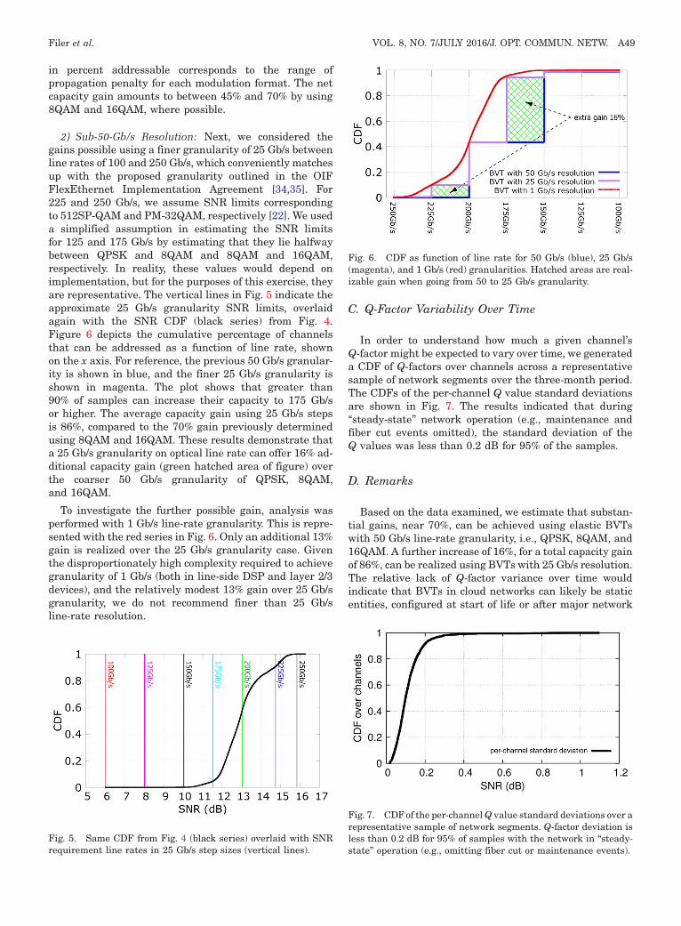
2) Sub-50-Gb/s Resolution: Next, we considered thegains possible using a finer granularity of 25 Gb/s betweenline rates of 100 and 250 Gb/s, which conveniently matchesup with the proposed granularity outlined in the OIFFlexEthernet Implementation Agreement [34,35]. For225 and 250 Gb/s, we assume SNR limits correspondingto 512SP-QAM and PM-32QAM, respectively [22]. We useda simplified assumption in estimating the SNR limitsfor 125 and 175 Gb/s by estimating that they lie halfwaybetween QPSK and 8QAM and 8QAM and 16QAM,respectively. In reality, these values would depend onimplementation, but for the purposes of this exercise, theyare representative. The vertical lines in Fig. 5 indicate theapproximate 25 Gb/s granularity SNR limits, overlaidagain with the SNR CDF (black series) from Fig. 4.Figure 6 depicts the cumulative percentage of channelsthat can be addressed as a function of line rate, shownon the x axis. For reference, the previous 50 Gb/s granular-ity is shown in blue, and the finer 25 Gb/s granularity isshown in magenta. The plot shows that greater than90% of samples can increase their capacity to 175 Gb/sor higher. The average capacity gain using 25 Gb/s stepsis 86%, compared to the 70% gain previously determinedusing 8QAM and 16QAM. These results demonstrate thata 25 Gb/s granularity on optical line rate can offer 16% ad-ditional capacity gain (green hatched area of figure) overthe coarser 50 Gb/s granularity of QPSK, 8QAM,and 16QAM.
To investigate the further possible gain, analysis wasperformed with 1 Gb/s line-rate granularity. This is repre-sented with the red series in Fig. 6. Only an additional 13%gain is realized over the 25 Gb/s granularity case. Giventhe disproportionately high complexity required to achievegranularity of 1 Gb/s (both in line-side DSP and layer 2/3devices), and the relatively modest 13% gain over 25 Gb/sgranularity, we do not recommend finer than 25 Gb/sline-rate resolution.
C. Q-Factor Variability Over Time
In order to understand how much a given channel’sQ-factor might be expected to vary over time, we generateda CDF of Q-factors over channels across a representativesample of network segments over the three-month period.The CDFs of the per-channel Q value standard deviationsare shown in Fig. 7. The results indicated that during“steady-state” network operation (e.g., maintenance andfiber cut events omitted), the standard deviation of theQ values was less than 0.2 dB for 95% of the samples.
D. Remarks
Based on the data examined, we estimate that substan-tial gains, near 70%, can be achieved using elastic BVTswith 50 Gb/s line-rate granularity, i.e., QPSK, 8QAM, and16QAM. A further increase of 16%, for a total capacity gainof 86%, can be realized using BVTs with 25 Gb/s resolution.The relative lack of Q-factor variance over time wouldindicate that BVTs in cloud networks can likely be staticentities, configured at start of life or after major network
Fig. 5. Same CDF from Fig. 4 (black series) overlaid with SNRrequirement line rates in 25 Gb/s step sizes (vertical lines).
Fig. 6. CDF as function of line rate for 50 Gb/s (blue), 25 Gb/s(magenta), and 1 Gb/s (red) granularities. Hatched areas are real-izable gain when going from 50 to 25 Gb/s granularity.
Fig. 7. CDFof the per-channelQ value standard deviations over arepresentative sample of network segments. Q-factor deviation isless than 0.2 dB for 95% of samples with the network in “steady-state” operation (e.g., omitting fiber cut or maintenance events).
Filer et al. VOL. 8, NO. 7/JULY 2016/J. OPT. COMMUN. NETW. A49

maintenance events only, not needing to adapt dynamicallyto changing network conditions.
IV. ELASTIC OLS PROOF-OF-CONCEPT
In this section we demonstrate in a laboratory environ-ment the operation of an elastic OLS that makes use ofthe technologies referenced in Section II. This is accom-plished using a commercially available DWDM line systemoperating in an open fashion, which is configured to trans-port Nyquist-shaped PM-QPSK signals at 32 GBaud over amix of ITU-T G.652 and G.655 fibers. The optical sourcesreside on a layer 2/3 modular Ethernet switch card withembedded coherent ASICs and corresponding CFP2-ACOpluggable optical modules. Transmission over 4000 kmof fiber with seven channels spaced 37.5 GHz apart isachieved with considerable OSNR margin. The results inthis section are a summary of the results published in [36].
A. Open Line System
A line system and approximately 4000 km of fiber wereprocured and installed in the optical transmission lab atMicrosoft’s Redmond headquarters. The transmissiontestbed has been configured to emulate large portions ofMicrosoft’s N.A. backbone network, with enough G.652standard SMF (Corning SMF-28e LL) and G.655 NZ-DSF (Corning LEAF) to pass traffic over two bidirectional∼2000 km paths. A summary of the span fiber types,
lengths, and associated amplification schemes is shownin Table I and Fig. 8 for the 2000 km forward path. Toachieve a full 4000 km transmission, the system is loopedback on itself after span 25.
The upper portion of Fig. 9 depicts the line system con-figuration, which utilizes a colorless architecture. Thereare colorless mux/demux and flexible-grid 20 deg ROADMsat network ingress and egress, and either 9 deg broadcast-and-select or 20 deg route-and-select flex-grid ROADMsafter every fifth span, primarily for channel power balanc-ing (these also allow for the option of future channel add/drop at these nodes). The spans range in length between 65and 120 km, with one span in every five long enough to re-quire backward-pumped Raman amplification in additionto EDFA (either every second or fourth span, shown by thedotted “R” modules in Fig. 9).
B. Coherent Linecard
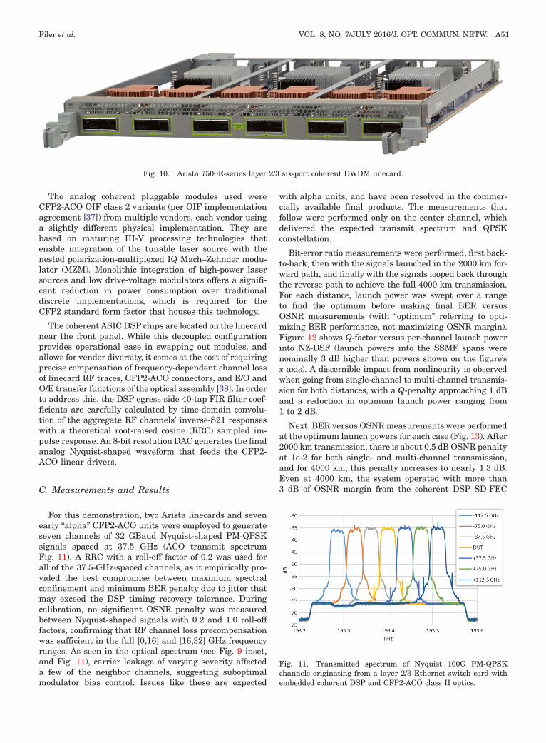
The optical sources used in the testbed reside on a layer2/3 modular switch card made by Arista (7500E-6CFPX,Fig. 10) for its 7500E platform. The linecard integratesthe 100-GbE Ethernet layer 2/3 switch silicon with wire-speed MACsec encryption and DSP silicon supporting co-herent PM-QPSK transmission over long-haul distances.Each linecard has six embedded coherent ASICs and cor-responding CFP2-ACO pluggable optical modules. This isdepicted in the gray lower box in Fig. 9; two linecards wereused to host the seven DSPs and ACO modules, but shownconceptually as one in the figure.
Fig. 8. Lab system fiber type and span length distributions.
TABLE IFIBER TYPE, DISTANCE, AND AMPLIFICATION SCHEME OF LAB
SYSTEM
Span Fiber km ps/nm Amplifier
1 G.652 SMF 75 1275 EDFA2 G.655 LEAF 75 375 EDFA3 G.655 LEAF 75 375 EDFA4 G.655 LEAF 110 550 EDFA�DRA5 G.655 LEAF 70 350 EDFA6 G.655 LEAF 65 325 EDFA7 G.655 LEAF 100 500 EDFA�DRA8 G.655 LEAF 65 325 EDFA9 G.655 LEAF 75 375 EDFA10 G.655 LEAF 70 350 EDFA11 G.655 LEAF 70 350 EDFA12 G.655 LEAF 75 375 EDFA13 G.655 LEAF 65 325 EDFA14 G.655 LEAF 90 450 EDFA�DRA15 G.655 LEAF 65 325 EDFA16 G.655 LEAF 70 350 EDFA17 G.655 LEAF 100 500 EDFA�DRA18 G.655 LEAF 75 375 EDFA19 G.655 LEAF 75 375 EDFA20 G.652 SMF 70 1190 EDFA21 G.652 SMF 65 1105 EDFA22 G.655 LEAF 75 375 EDFA23 G.655 LEAF 75 375 EDFA24 G.655 LEAF 120 600 EDFA�DRA25 G.652 SMF 75 1275 EDFATotal 1945 13,145
Fig. 9. 4000 km optical transmission testbed—elastic OLS withcoherent layer 2/3 Ethernet linecard as source.
A50 J. OPT. COMMUN. NETW./VOL. 8, NO. 7/JULY 2016 Filer et al.
The analog coherent pluggable modules used wereCFP2-ACO OIF class 2 variants (per OIF implementationagreement [37]) from multiple vendors, each vendor usinga slightly different physical implementation. They arebased on maturing III-V processing technologies thatenable integration of the tunable laser source with thenested polarization-multiplexed IQ Mach–Zehnder modu-lator (MZM). Monolithic integration of high-power lasersources and low drive-voltage modulators offers a signifi-cant reduction in power consumption over traditionaldiscrete implementations, which is required for theCFP2 standard form factor that houses this technology.
The coherent ASIC DSP chips are located on the linecardnear the front panel. While this decoupled configurationprovides operational ease in swapping out modules, andallows for vendor diversity, it comes at the cost of requiringprecise compensation of frequency-dependent channel lossof linecard RF traces, CFP2-ACO connectors, and E/O andO/E transfer functions of the optical assembly [38]. In orderto address this, the DSP egress-side 40-tap FIR filter coef-ficients are carefully calculated by time-domain convolu-tion of the aggregate RF channels’ inverse-S21 responseswith a theoretical root-raised cosine (RRC) sampled im-pulse response. An 8-bit resolution DAC generates the finalanalog Nyquist-shaped waveform that feeds the CFP2-ACO linear drivers.
C. Measurements and Results
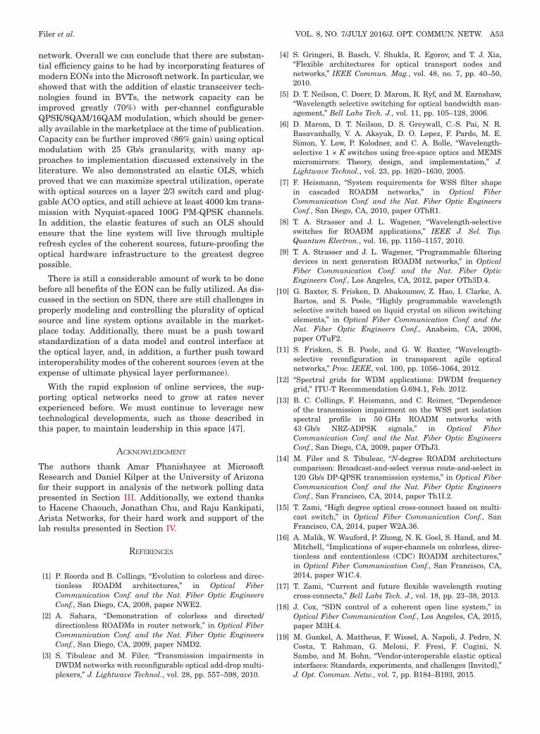
For this demonstration, two Arista linecards and sevenearly “alpha” CFP2-ACO units were employed to generateseven channels of 32 GBaud Nyquist-shaped PM-QPSKsignals spaced at 37.5 GHz (ACO transmit spectrumFig. 11). A RRC with a roll-off factor of 0.2 was used forall of the 37.5-GHz-spaced channels, as it empirically pro-vided the best compromise between maximum spectralconfinement and minimum BER penalty due to jitter thatmay exceed the DSP timing recovery tolerance. Duringcalibration, no significant OSNR penalty was measuredbetween Nyquist-shaped signals with 0.2 and 1.0 roll-offfactors, confirming that RF channel loss precompensationwas sufficient in the full [0,16] and [16,32] GHz frequencyranges. As seen in the optical spectrum (see Fig. 9 inset,and Fig. 11), carrier leakage of varying severity affecteda few of the neighbor channels, suggesting suboptimalmodulator bias control. Issues like these are expected
with alpha units, and have been resolved in the commer-cially available final products. The measurements thatfollow were performed only on the center channel, whichdelivered the expected transmit spectrum and QPSKconstellation.
Bit-error ratio measurements were performed, first back-to-back, then with the signals launched in the 2000 km for-ward path, and finally with the signals looped back throughthe reverse path to achieve the full 4000 km transmission.For each distance, launch power was swept over a rangeto find the optimum before making final BER versusOSNR measurements (with “optimum” referring to opti-mizing BER performance, not maximizing OSNR margin).Figure 12 shows Q-factor versus per-channel launch powerinto NZ-DSF (launch powers into the SSMF spans werenominally 3 dB higher than powers shown on the figure’sx axis). A discernible impact from nonlinearity is observedwhen going from single-channel to multi-channel transmis-sion for both distances, with a Q-penalty approaching 1 dBand a reduction in optimum launch power ranging from1 to 2 dB.
Next, BER versus OSNRmeasurements were performedat the optimum launch powers for each case (Fig. 13). After2000 km transmission, there is about 0.5 dB OSNR penaltyat 1e-2 for both single- and multi-channel transmission,and for 4000 km, this penalty increases to nearly 1.3 dB.Even at 4000 km, the system operated with more than3 dB of OSNR margin from the coherent DSP SD-FEC
Fig. 10. Arista 7500E-series layer 2/3 six-port coherent DWDM linecard.
Fig. 11. Transmitted spectrum of Nyquist 100G PM-QPSKchannels originating from a layer 2/3 Ethernet switch card withembedded coherent DSP and CFP2-ACO class II optics.
Filer et al. VOL. 8, NO. 7/JULY 2016/J. OPT. COMMUN. NETW. A51

threshold. Propagation with a fully filled 120-channelspectrum could be expected to generate additional OSNRpenalty on the order of 1� 0.2 dB [39,40].
D. Remarks
For Microsoft, this demonstration was the first step inshowing the feasibility of a truly elastic and flexible OLS.We were able to demonstrate a line system based on color-less, flexible-grid technology interoperating with aliensources residing in a layer 3 Ethernet switch platform, withno perceivable implementation penalty over a more tradi-tional “locked” line system with vendor-specific transpon-ders [41–43]. At the time of the measurements, we werenot able to fully leverage the bandwidth-variable propertyof the coherent sources, but this testbed is permanent andthese types of demonstrations will be done in the nearfuture.
V. SOFTWARE-DEFINED NETWORKING
Microsoft’s wide-area network (WAN) spans the globe,and is one of the larger networks in the Internet. A diverseset of services runs across the WAN, ranging from
enterprise cloud applications and email to search and cloudstorage. This service diversity leads to a diverse set ofrequirements on the WAN. For example, enterprise appli-cations must experience near-perfect availability, highcapacity, and the flexibility to change with unpredictableservice adoption. On the other hand, internal storage rep-lication across data centers can be treated with low priority,and although it produces a large volume of traffic, this canbe scheduled and planned around the needs of the higherpriority traffic. The combination of scale and applicationdiversity presents significant operational challenges.
SDN enables centralized management and control ofnetwork infrastructure [44], and this ability has beenleveraged by Microsoft to boost the efficiency of its WANinfrastructure [45]. Our current SDN approach, calledSWAN (software-defined wide-area network), assumesthat the optical layer is static and dynamically computesrouting paths to drive high utilization on theWAN. In otherwords, it moves bits around to best fit into the fixed infra-structure. Examples include routing around failures, re-moving or inserting low priority traffic as necessary, andautomatically turning up nodes after new infrastructureinstallation or new service activation. In operation, SWANmeasures an observed state from the network and services,computes a desired network state, and automatically ap-plies state changes to the network.
Elastic optics can enable further optimization of the net-work, through the use of BVTs and ROADMs. However,when considering the scale, diversity, and multi-vendornature of our WAN, this could add enormous complexity tothe operation of the network. To cope with the added com-plexity, today the elastic features are configured at start-of-life to a precalculated optimum and minimal adjustmentsare made, manually, as required. To extract the full poten-tial of elastic optics, SWAN needs to be extended to includedynamic control of the optical layer. To achieve this, twochallenges need to be addressed. The first is to develop astandard data model and control interface for the opticallayer, as was done for the IP layer [46]. YANG, RESTCONF,and SNMP provide potential starting points for such amodel. The physical models that define optical perfor-mance would also need to be made available, with standardoutputs consumable by the controller to dynamically deter-mine desired states. Once under operation, ideally, theline-side optics and photonic line hardware would be inter-operable and interchangeable, even across vendors, so thenetwork and the SDN controller can operate seamlesslythrough technology cycles, agnostic to vendor or hardwarevariant. The second challenge is computational. Elastic op-tics, combined with routing flexibility, offer a vast numberof possibilities for configuring the network. Efficient opti-mization techniques are needed to quickly compute net-work configurations that deliver high performance basedon current traffic demand.
VI. CONCLUSION
In this paper, we have examined the implications ofthe EON paradigm on Microsoft’s long-haul data center
Fig. 13. BER versus OSNR at optimal launch powers for NyquistPM-QPSK signals over an elastic OLS testbed.
Fig. 12. Q versus launch power into NZ-DSF spans (power intoSSMF spans was 3 dB lower than values shown) for NyquistPM-QPSK signals over an elastic OLS testbed.
A52 J. OPT. COMMUN. NETW./VOL. 8, NO. 7/JULY 2016 Filer et al.
network. Overall we can conclude that there are substan-tial efficiency gains to be had by incorporating features ofmodern EONs into the Microsoft network. In particular, weshowed that with the addition of elastic transceiver tech-nologies found in BVTs, the network capacity can beimproved greatly (70%) with per-channel configurableQPSK/8QAM/16QAM modulation, which should be gener-ally available in the marketplace at the time of publication.Capacity can be further improved (86% gain) using opticalmodulation with 25 Gb/s granularity, with many ap-proaches to implementation discussed extensively in theliterature. We also demonstrated an elastic OLS, whichproved that we can maximize spectral utilization, operatewith optical sources on a layer 2/3 switch card and plug-gable ACO optics, and still achieve at least 4000 km trans-mission with Nyquist-spaced 100G PM-QPSK channels.In addition, the elastic features of such an OLS shouldensure that the line system will live through multiplerefresh cycles of the coherent sources, future-proofing theoptical hardware infrastructure to the greatest degreepossible.
There is still a considerable amount of work to be donebefore all benefits of the EON can be fully utilized. As dis-cussed in the section on SDN, there are still challenges inproperly modeling and controlling the plurality of opticalsource and line system options available in the market-place today. Additionally, there must be a push towardstandardization of a data model and control interface atthe optical layer, and, in addition, a further push towardinteroperability modes of the coherent sources (even at theexpense of ultimate physical layer performance).
With the rapid explosion of online services, the sup-porting optical networks need to grow at rates neverexperienced before. We must continue to leverage newtechnological developments, such as those described inthis paper, to maintain leadership in this space [47].
ACKNOWLEDGMENT
The authors thank Amar Phanishayee at MicrosoftResearch and Daniel Kilper at the University of Arizonafor their support in analysis of the network polling datapresented in Section III. Additionally, we extend thanksto Hacene Chaouch, Jonathan Chu, and Raju Kankipati,Arista Networks, for their hard work and support of thelab results presented in Section IV.
REFERENCES
[1] P. Roorda and B. Collings, “Evolution to colorless and direc-tionless ROADM architectures,” in Optical FiberCommunication Conf. and the Nat. Fiber Optic EngineersConf., San Diego, CA, 2008, paper NWE2.
[2] A. Sahara, “Demonstration of colorless and directed/directionless ROADMs in router network,” in Optical FiberCommunication Conf. and the Nat. Fiber Optic EngineersConf., San Diego, CA, 2009, paper NMD2.
[3] S. Tibuleac and M. Filer, “Transmission impairments inDWDM networks with reconfigurable optical add-drop multi-plexers,” J. Lightwave Technol., vol. 28, pp. 557–598, 2010.
[4] S. Gringeri, B. Basch, V. Shukla, R. Egorov, and T. J. Xia,“Flexible architectures for optical transport nodes andnetworks,” IEEE Commun. Mag., vol. 48, no. 7, pp. 40–50,2010.
[5] D. T. Neilson, C. Doerr, D. Marom, R. Ryf, and M. Earnshaw,“Wavelength selective switching for optical bandwidth man-agement,” Bell Labs Tech. J., vol. 11, pp. 105–128, 2006.
[6] D. Marom, D. T. Neilson, D. S. Greywall, C.-S. Pai, N. R.Basavanhally, V. A. Aksyuk, D. O. Lopez, F. Pardo, M. E.Simon, Y. Low, P. Kolodner, and C. A. Bolle, “Wavelength-selective 1 × K switches using free-space optics and MEMSmicromirrors: Theory, design, and implementation,” J.Lightwave Technol., vol. 23, pp. 1620–1630, 2005.
[7] F. Heismann, “System requirements for WSS filter shapein cascaded ROADM networks,” in Optical FiberCommunication Conf. and the Nat. Fiber Optic EngineersConf., San Diego, CA, 2010, paper OThR1.
[8] T. A. Strasser and J. L. Wagener, “Wavelength-selectiveswitches for ROADM applications,” IEEE J. Sel. Top.Quantum Electron., vol. 16, pp. 1150–1157, 2010.
[9] T. A. Strasser and J. L. Wagener, “Programmable filteringdevices in next generation ROADM networks,” in OpticalFiber Communication Conf. and the Nat. Fiber OpticEngineers Conf., Los Angeles, CA, 2012, paper OTh3D.4.
[10] G. Baxter, S. Frisken, D. Abakoumov, Z. Hao, I. Clarke, A.Bartos, and S. Poole, “Highly programmable wavelengthselective switch based on liquid crystal on silicon switchingelements,” in Optical Fiber Communication Conf. and theNat. Fiber Optic Engineers Conf., Anaheim, CA, 2006,paper OTuF2.
[11] S. Frisken, S. B. Poole, and G. W. Baxter, “Wavelength-selective reconfiguration in transparent agile opticalnetworks,” Proc. IEEE, vol. 100, pp. 1056–1064, 2012.
[12] “Spectral grids for WDM applications: DWDM frequencygrid,” ITU-T Recommendation G.694.1, Feb. 2012.
[13] B. C. Collings, F. Heismann, and C. Reimer, “Dependenceof the transmission impairment on the WSS port isolationspectral profile in 50 GHz ROADM networks with43 Gb/s NRZ-ADPSK signals,” in Optical FiberCommunication Conf. and the Nat. Fiber Optic EngineersConf., San Diego, CA, 2009, paper OThJ3.
[14] M. Filer and S. Tibuleac, “N-degree ROADM architecturecomparison: Broadcast-and-select versus route-and-select in120 Gb/s DP-QPSK transmission systems,” in Optical FiberCommunication Conf. and the Nat. Fiber Optic EngineersConf., San Francisco, CA, 2014, paper Th1I.2.
[15] T. Zami, “High degree optical cross-connect based on multi-cast switch,” in Optical Fiber Communication Conf., SanFrancisco, CA, 2014, paper W2A.36.
[16] A. Malik, W. Wauford, P. Zhong, N. K. Goel, S. Hand, and M.Mitchell, “Implications of super-channels on colorless, direc-tionless and contentionless (CDC) ROADM architectures,”in Optical Fiber Communication Conf., San Francisco, CA,2014, paper W1C.4.
[17] T. Zami, “Current and future flexible wavelength routingcross-connects,” Bell Labs Tech. J., vol. 18, pp. 23–38, 2013.
[18] J. Cox, “SDN control of a coherent open line system,” inOptical Fiber Communication Conf., Los Angeles, CA, 2015,paper M3H.4.
[19] M. Gunkel, A. Mattheus, F. Wissel, A. Napoli, J. Pedro, N.Costa, T. Rahman, G. Meloni, F. Fresi, F. Cugini, N.Sambo, and M. Bohn, “Vendor-interoperable elastic opticalinterfaces: Standards, experiments, and challenges [Invited],”J. Opt. Commun. Netw., vol. 7, pp. B184–B193, 2015.
Filer et al. VOL. 8, NO. 7/JULY 2016/J. OPT. COMMUN. NETW. A53

[20] D. O’shea, “DCI boxes aren’t just for metros anymore,”Sept. 23, 2015 [Online]. Available: http://www.lightreading.com/data‑center/data‑center‑interconnect‑/dci‑boxes‑arent‑just‑for‑metros‑anymore/a/d‑id/718343.
[21] Y. Yoshida, A. Maruta, K.-I. Kitayama, M. Nishihara, T.Tanaka, T. Takahara, J. C. Rasmussen, N. Yoshikane, T.Tsuritani, I. Morita, S. Yan, Y. Shu, Y. Yan, R. Nejabati,G. Zervas, D. Simeonidou, R. Vilalta, R. Munoz, R.Casellas, R. Martinez, A. Aguado, V. Lopez, and J.Marhuenda, “SDN-based network orchestration of variable-capacity optical packet switching network over program-mable flexi-grid elastic optical path network,” J. LightwaveTechnol., vol. 33, pp. 609–617, 2015.
[22] J. K. Fischer, “Bandwidth-variable transceivers based onfour-dimensional modulation formats,” J. Lightwave Technol.,vol. 32, pp. 2886–2895, 2014.
[23] B. Teipen, M. H. Eiselt, K. Grobe, and J.-P. Elbers, “Adaptivedata rates for flexible transceivers in optical networks,”J. Netw., vol. 7, pp. 776–782, 2012.
[24] K. Roberts and C. Laperle, “Flexible transceivers,” in Proc.European Conf. on Optical Communications, Amsterdam,The Netherlands, 2012, paper We.3.A.3.
[25] M. Kuschnerov, “Flexi-rate optical interfaces go mainstream,”June 12, 2015 [Online]. Available: http://www.lightwaveonline.com/articles/2015/06/flexi‑rate‑optical‑interfaces‑go‑mainstream.html.
[26] “Acacia Communications announces the industry’s firstcoherent flex-rate 400G 5 × 7 transceiver model,” Mar. 22,2015 [Online]. Available: http://acacia‑inc.com/acacia‑communications‑announces‑the‑industrys‑first‑coherent‑flex‑rate‑400g‑5x7‑transceiver‑module.
[27] X. Zhou, L. E. Nelson, P. Magill, R. Isaac, B. Zhu, D. W.Peckham, P. I. Borel, and K. Carlson, “High spectral efficiency400 Gb/s transmission using PDM time-domain hybrid 32–64QAM and training-assisted carrier recovery,” J. LightwaveTechnol., vol. 31, pp. 999–1005, 2013.
[28] Q. Zhuge, X. Xu, M. Morsy-Osman, M. Chagnon, M. Qiu, andD. V. Plant, “Time domain hybrid QAM based rate-adaptiveoptical transmissions using high speed DACs,” in OpticalFiber Communication Conf., Anaheim, CA, 2013, paperOTh4E.6.
[29] H. Bulow, T. Rahman, F. Buchali, W. Idler, and W. Kuebart,“Transmission of 4-D modulation formats at 28-Gbaud,” inOptical Fiber Communication Conf., Anaheim, CA, 2013,paper JW2A.39.
[30] M. Karlsson and E. Agrell, “Spectrally efficient four-dimensional modulation,” in Optical Fiber CommunicationConf. and the Nat. Fiber Optic Engineers Conf., Los Angeles,CA, 2012, paper OTu2C.1.
[31] L. Beygi, E. Agrell, J. M. Kahn, and M. Karlsson, “Codedmodulation for fiber-optic networks,” IEEE Signal Process.Mag., vol. 31, no. 2, pp. 93–103, 2014.
[32] M. Ghobadi, J. Gaudette, R. Mahajan, A. Phanishayee, B.Klinkers, and D. Kilper, “Evaluation of elastic modulationgains in Microsoft’s optical backbone in North America,”
in Optical Fiber Communication Conf., Anaheim, CA, 2016,paper M2J.2.
[33] A. Carena, V. Curri, G. Bosco, P. Poggiolini, and F. Forghieri,“Modeling of the impact of nonlinear propagation effects inuncompensated coherent transmission links,” J. LightwaveTechnol., vol. 30, pp. 1524–1539, 2012.
[34] OIF Implementation Agreement for FlexEthernet, documentoif2015.127.
[35] S. Hardy, “Ethernet speed tuning goal of OIF FlexEthernetproject,” Feb. 12, 2015 [Online]. Available: http://www.lightwaveonline.com/articles/2015/02/ethernet‑speed‑tuning‑goal‑of‑oif‑flexethernet‑project.html.
[36] M. Filer, H. Chaouch, J. Chu, R. Kankipati, and T. Issenhuth,“Transmission of Nyquist-shaped 32 GBaud PM-QPSK overa production flex-grid open line system,” in Optical FiberCommunication Conf., Anaheim, CA, 2016, paper W4G.3.
[37] OIF Implementation Agreement for CFP2-Analogue CoherentOptics Module, document oif2014.006.
[38] T. Duthel, P. Hermann, T. Winkler von Mohrenfels, J.Whiteaway, and T. Kupfer, “Challenges with pluggable opticalmodules for coherent optical communication systems,” inOptical Fiber Communication Conf., San Francisco, CA,2014, paper W3K.2.
[39] C. Xia, W. Schairer, A. Striegler, L. Rapp, M. Kuschnerov,J. F. Pina, and D. van den Borne, “Impact of channelcount and PMD on polarization-multiplexed QPSK trans-mission,” J. Lightwave Technol., vol. 29, pp. 3223–3229,2011.
[40] http://nlinwizard.eng.tau.ac.il/, retrieved Mar. 18, 2016.[41] L. E. Nelson, G. Zhang, M. Birk, C. Skolnick, R. Isaac,
Y. Pan, C. Rasmussen, G. Pendock, and B. Mikkelsen, “Arobust real-time 100G transceiver with soft-decision forwarderror correction [Invited],” J. Opt. Commun. Netw., vol. 4,pp. B131–B141, 2012.
[42] K. Roberts, F. S. Heng, M. Moyer, M. Hubbard, A. Sinclair, J.Gaudette, and C. Laperle, “High capacity transport—100Gand beyond,” J. Lightwave Technol., vol. 33, pp. 563–578,2015.
[43] http://www.cisco.com/c/en/us/products/collateral/optical‑networking/network‑convergence‑system‑2000‑series/datasheet‑c78‑733699.html, retrieved Jan. 15, 2016.
[44] S. Gringeri, N. Bitar, and T. J. Xia, “Extending softwaredefined network principles to include optical transport,”IEEE Commun. Mag., vol. 51, no. 3, pp. 32–40, 2013.
[45] C.-Y. Hong, S. Kandula, R. Mahajan, M. Zhang, V. Gill, M.Nanduri, and R. Wattenhofer, “Achieving high utilizationwith software-driven WAN,” in Proc. SIGCOMM, Hong Kong,China, 2013.
[46] P. Sun, R. Mahajan, J. Rexford, L. Yuan, M. Zhang, and A.Arefin, “A network-state management service,” in Proc.SIGCOMM, Chicago, IL, 2014.
[47] A. Bartels, J. R. Rymer, J. Staten, K. Kark, J. Clark, andD. Whittaker, “The public cloud is now in hypergrowth,”Forrester Research Report, Apr. 24, 2014.
A54 J. OPT. COMMUN. NETW./VOL. 8, NO. 7/JULY 2016 Filer et al.