elastic compression of spheres and cylinders at point and ...elastic compression of spheres and...
TRANSCRIPT

Elastic Compression of Spheres and Cylinders
at Point and Line Contact
By M. J. Puttock and E. G. Thwaite
National Standards Laboratory Technical Paper No. 25
Commonwealth Scientific and Industrial
Research Organization, Australia
Melbourne 1969

Printed by CSIRO, Melbourne

CONTENTS
Summary 5Symbols 6
Part 1. COMPRESSION FORMULAE
3
Case 1.2.3.4.
5.
6.
7.
8.
9.10.11.
12.
13.
14.
15.
16.
Two spheres in contactSphere in contact with a planeSphere between two parallel planesSphere in contact with an internalspherical surfaceEqual diameter cylinders crossed withtheir axes at right anglesUnequal diameter cylinders crossedwith their axes at right anglesUnequal diameter cylinders crossedwith their axes at any angleTwo cylinders in contact with axesparallelCylinder in contact with a planeCylinder between two parallel planesSphere in contact with a cylinder(external)Sphere in contact with a cylinder(internal)Sphere in contact with a symmetricalcylindrical vee grooveSphere in contact with an asymmetricalcylindrical vee grooveCylinder in contact with an asymmetricalcylindrical vee grooveCylinder in contact with a symmetricalcylindrical vee groove
789
10
11
12
13
141516
17
18
19
20
22
24
Part 2. THEORY
I. Introduction
II. General Theory(a) General(b) Geometry of the unstressed surface
in the region of contact(c) Equations for area of contact,
pressure distribution and compression
III. Special Cases(a) Two spheres in contact(b) Sphere in contact with a plane(c) Sphere in contact with an
internal sphere(d) Equal cylinders crossed at
right angles
25
26
26
33
3738
38
39

4
(e) Unequal cylinders crossed atright angles
(f) Unequal diameter cylinders crossedwith their axes at any angle
(g) Sphere on a cylinder(h) Sphere inside a cylinder(i) Cylinders in contact along a line
parallel to their axes and a cylinderon a plane
IV. References
39
434344
45
49
Appendix I.
Appendix II.
Tables of elastic constants andderived quantities
Values of elliptic integral K, the· 1 dE d i··quant1ty - e de an eccentr c1t1es
for arguments AlB
51
56

ELASTIC COMPRESSION OF SPHERES AND CYLINDERSAT POINT AND LINE CONTACT
By M.J. Puttock* and E.G. Thwaite*
Summary
The purpose of this paper is primarily to presentin a convenient form the formulae and data for thecalculation of the compression effects which occur inthe measurement and use of spheres and cylinders indimensional metrology.
Only Hertzian compression effects are consideredin the present paper and these assume that thesurfaces in contact are perfectly smooth, that theelastic limits of the materials are not exceeded,that the materials are homogeneous, and that thereare no frictional forces within the contact area.These conditions are closely met with materials andapplied forces normally encountered in precisedimensional metrology, and with the surfaces finelylapped.
In the case of surfaces that are not finely lappedthe actual compression effects may differ by up to10% from those calculated using the formulae in thispaper. Contributory factors include frictionalforces and microstructure variations in the surfaceleading to variations in elastic modulii. Berndt(1928) has derived modified formulae to take intoaccount frictional forces arising from non-smoothsurfaces and these formulae, in general, lead tocompression effects differing from those in thispaper by approximately 5%.
It is considered that the formulae given in thispaper are sufficiently precise for all practicalpurposes in precise dimensional metrology.
This paper is in two parts. Part 1 is a series ofdata sheets giving the appropriate formulae forvarious specific cases, together with appropriatetables and graphs. Part 2 gives the mathematicalderivation of the formulae in a consistent notationand is primarily intended for students with aninterest in the subject.
Where the formulae have been partially evaluatedfor steel the elastic constants used have been thosefor 1% carbon steel.
*Division of Applied Physics, National Standards Laboratory, CSIRO,University Grounds, Chippendale, N.S.W. 2008.
5

6
SYMBOLS
Units
the total elastic compression at the point
or line of contact of two bodies, measured
along the line of the applied force
mm in
D diameter of body
P total applied force
E Young's modulus of material of body
modulus of rigidity of material of body
gf lbf
mm in
gf/mm2 lbf/in2
gf/mm2 Ibf/in2
mm2 /gf in 2/ Ibf
mm 2 /gf in 2 /1bf
E/2G - 1Poisson's ratio
(1 - 02
) /rrE
34 (VI + V2 ) for bodies of different
materials
v
a
G
Q
32 V for bodies of the same material
e eccentricity of ellipse of contact
(1 - b2 /a 2 )1/2
K and E* are the complete elliptic integrals of
the first .and second class respectively
with modulus e
*Not to be confused with E, the Young's modulus.

Case 1.
PART 1
COMPRESSION FORMULAE
Two Spheres in Contact
7
p p
The suffixes 1 and 2 relate to spheres 1 and 2 respectively.
General Case
(3TI)2/3 / / 1 1 /(), = -2- · p2 3 • ( VI + V2) 2 3 • (_ + _) 1 3.
D1 D2
Spheres of Same Material
Spheres Both of Steel
Metric Units: P in gf, D in mm
mm.
Inch Units: P in Ibf, D in inch
(), = 0.000 016 . p2/3 • (l- + l-)1/3 inch.VI D2

8
Case 2. Sphere in Contact with a Plane
General Case
(3-rr) 2/3 / / 1 /a = 2 II • p2 3 • (V 1 + V2) 2 3 • (/5) 1 3.
Sphere and Plane of Same Material
Sphere and Plane Both of Steel
Metric Units: p in gf, D in nun
a = 0.000 020 p2/3 (!.) 1/3 mm.D
Inch Units: P in lbf, D in inch
a = 0.000 016 p2/3 (2:.)1/3 inch.D

Case 3. SEhere Between Two Parallel Planes
p
9
Total compression aT = aa + ab where aa and ab are calculated asin Case 2.
If the two planes are of the same material then
and the total compression may be written as
2a.
Sphere and Planes All of Steel
Metpio Units: P in gf, D in mm
aT 0.000 040 p2/3 (2:.) 1/3 mm.D
Inch Units: P in lbf, D in inch
aT 0.000 032 p2/3 (l) 1 /3 inch.D
10
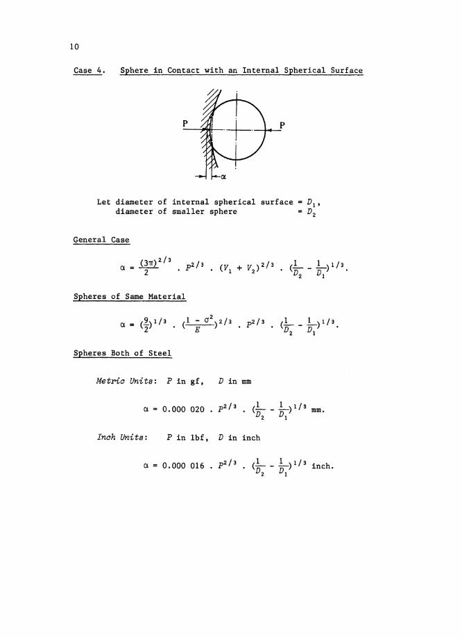
Case 4. Sphere in Contact with an Internal Spherical Surface
p
Let diameter of internal spherical surface = D1 ,
diameter of smaller sphere = D2
General Case
(3n)2/3 / / 1 1 /a. =:: -2-- . p2 3 • (VI + V2
) 2 3 • ( ) 1 3D2 VI •
Spheres of Same Material
a =
Spheres Both of Steel
Metria Units: P in gf, D in mm
Inch Units: P in lbf, D in inch
a = 0.000 016 • p 2/
3 • (!- - 1-)1/3 inch.D2 VI
11
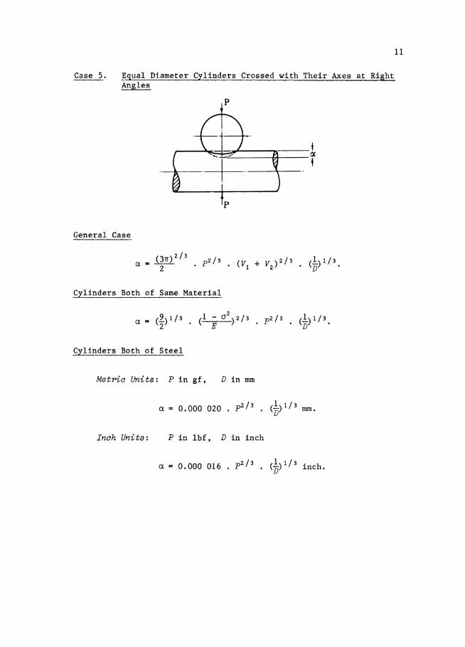
Case 5. Equal Diameter Cylinders Crossed with Their Axes at RightAngles
~----t,---~......",;.------+,...--...--~
+
General Case
( 3TI)2/3 / / 1 /Q, = -2-- · p2 3 • ( VI + V2 ) 2 3 • (Jj) 1 3.
Cylinders Both of Same Material
Cylinders Both of Steel
Met'Pia Units: P in gf, D in mm
ex. = 0.000 020 p2/3 (!.) 1/3 mm.D
Inch Units: P in Ibf, D in inch
ex = 0.000 016 p2/3 (!')1/3 inch.D

12
Cas~ 6. Unequal Diameter Cylinders Crossed with Their Axes at RightAngles
pCylinder 2
Cylinder 1
and
where
The suffix 1 refers to the larger diameter cylinder, the suffix 2to the smaller.
General Case1/3
a = 2K. (P • Q) 2/3 • ( 1 1 dE] ,2D1 • (- e de)
1 dE A D2Kand - e de are functions of B = ~ '
Q = t (V1 + V2 ) for dissimilar materials,
Q = t V when cylinders are of the same material,
A D2For any given value of 13 =D in the range 1.00 to 0.000 000 1
1 1 dEthe corresponding values of K and - e de may be obtained from Tables 3-6
or Figure 6.
Both Cylinders of Steel
Metric Units: P in gf, D in mm
1/3
a = 0.000 015 . K . p2/3 • ( 1 1 dE ] mm.2D1 • (- e de)
Inch Units: P in lbf, D in inch
1/3
a = 0.000 012 . K . p2
/3
• ( 1 1 dE ] inch.2D1 • (- e de)

Case 7. Unequal Diameter Cylinders Crossed with Their Axes at AnyAngle
13
Cylinder 1 Cylinder 2
The suffix 1 refers to the larger diameter cylinder, the suffix 2to the smaller.
Let the axes be inclined at an acute angle e to one another.It is first necessary to obtain the ratio A/B by solving the
following equations, for A and B.
A+B=L+LD1
D2
~
{A _ B)2 = (L)2 + (L.)2 + 2 cos 28VI D2 D1V2
1 dEFrom the calculated value of A/B the values of K and - e de maybe obtained from Tables 3-6 or Figure 6.
General Case1/3
a = 2K • (P • Q) 2/3 • ( A 1 dE) ,2 • (- e de)
where
and
3Q = 4 (VI + V2 ) for dissimilar materials
Q = t V when cylinders are of the same material.
Both Cylinders of Steel
Metnc Units: P in gf, D in mm
a = 0.000 015 • K · p2/a • (2
1/3
A 1 dE ) mm.(- --)e de
Inch Units: P in lbf, D in inch
1/3
a = 0.000 012 . K . p2/
3• ( A 1 dE ] inch.
2 • (- e de)

14
Case 8. Two Cylinders in Contact with Axes Parallel
_ ......... --r-JE.----t~~__a.
i2a
Cylinder 2
Cylinder 1
General Case
Same Materials
a = 2P . V • G+ In { 4a2
_ • (L + L)}~.LV. P D1 D2 ~
Both Diameters Equal
• D~'Same Materials
P = P/2a = force per unit length.In = natural logarithm.2a = length of contact.

Case 9. Cylinder in Contact with a Plane
15
f ; Cylinder t-V,@/~W/~~2a~
Cylinder
General Case
Same Materials
P = Pl2a = force per unit length.In = natural logarithm.2a = length of contact.

16
Case 10. Cylinder Between Two
r-2a~
(a) (b)
Planes
(c)
The calculations are as for Case 9.If the lengths of the lines of contact are the same (as in (a)
and (b)), and the material of the two planes is also the same, thenthe total compression is twice the compression for a single contact,i.e.
2a.
If the lengths of the lines of contact are not equal (such as in(0)), or the materials of the two planes are different, then thecompressions at each contact must be calculated independently, i.e.

Case 11. Sphere in Contact with a Cylinder (External)
p
17
Sphere
Cylinder
Let diameter of sphere DIand diameter of cylinder Dz
First obtain the ratio AlB and the value of 11A from the followingequations:
1A n;B = 1 l'-+D
I. D
z
From the calculated value of AlB, obtain the appropriate values
of Kand - 1 ddE from Tables 3-6 or Figure 6.e eCalculate a from the following equation
1 dE- e de ·
Then calculate the compression a from the equation
r\I = 2QP Ku. .,a
where 3Q = 4 (VI + V2 ) for dissimilar materials,
Q = } V for similar materials.

18
Case 12. Sphere in Contact with a Cylinder (Internal)
Let diameter of sphere DIand diameter of cylinder D2
First obtain the ratio AlB and the value of 11A from the followingequations:
1 1---
A DI D2
13 = 1
F;1 1if = -1---1-
F; - D2
From the calculated value of AlB obtain the appropriate values
of K and - 1 ddE from Tables 3-6 or Figure 6.e eCalculate a from the following equation
2QPA
1 dE- e de ·
Then calculate the compression a from the equation:
2QPa. = -- • K,a
where 3Q = 4 (Vi + V2 ) for dissimilar materials,
Q = 1 V for similar materials.2

Case 13.
19
Sphere in Contact with a Cylindrical Vee Groove, the VeeGroove Being Symmetrical with Respect to a Nonnal to theAxis of the Cylinder
SphereVee - groove cylinder ex
Let diameter of sphere = D,diameter of cylinder at point of contact DE'semi-angle of vee groove = 8.
(1) Calculate the value of AlB from
1A DJj=l+ 1
D DE cosec e
(2)
(3)
1 dEObtain appropriate values of Kand - e de from Tables 3-6 orFigure 6.
Calculate a from the equation
1 dEQP cosec e · D • - e de ·
(4) Calculate the total compression a normal to the axis of thecylinder from the equation
QP cosec 2 ea = . K,a
where
and
3Q = 4 (V1 + V2 ) for dissimilar materials,
3Q = 2 V for sphere and cylindrical vee groove of the samematerial.

20
Case 14. Sphere in Contact with a Cylindrical Vee Groove, the VeeGroove Being ASymmetrical with Respect to a Normal to theAxis of the Cylinder
Vee -groove
Axis of
cylinder
Let diameter of sphere = D,angles vee groove flanks make with normal to vee cylinderaxis = 81 and 82 ,
diameters of vee cylinder at points of contact = DEI andDE2 respectively.
Initially each contact point must be treated separately.
(1) Calculate the values of AlB from equations:
1D
1D
(2)
(3)
1 dEObtain appropriate values of K and - e de for each case fromTables 3-6 or Figure 6.
Calculate relevant values of a from the equations:
a 3 2Q • P • D (1 dE)2 tan 8 1 cos 82 + sin e2· - e de 2·
(4) Calculate the relevant compressions normal to the vee grooveflanks from the equations:

21
2QPa1(tan 82 cos 81 + sin 61) · K1
and
2QP( ) · K2a2 tan e1 cos e2 + sin e2 '
where 3Q =4 (VI + V2) for dissimilar materials,
3Q = 2 V where both sphere and cylindrical vee groove areof the same material.
(5) Calculate total compression effect a normal to vee cylinder axisfrom the equation

22
Case 15. Cylinder in Contact with a Cylindrical Vee Groove, theVee Groove Being Asymmetrical with Respect to a Normalto the Vee Cylinder
Vee -groove
Axis of---......--..-t --+7~- 7'-+--7t---+-.,- ~~--r- ;---,........,......~.-..- """"'----
cylinder
Let diameter of cylinder = D,angles vee groove flanks make with normal to vee cylinderaxis = 81 and 62'diameters of vee cylinder at points of contact = DEI andDE2 respectively.
Initially each contact must be treated separately.
(1) Calculate values of AlB from the equations:
D D
(2)
(3)
1 dEObtain appropriate values of Kand - e de for each case fromTables 3-6 or Figure 6.
Calculate relevant values of a from the equations:
2QPDE1 cosec 81 1 dEat tan 8 2 cos 8 1 + sin 8 1 • (- e de) l'
2QPDE2
cosec 82
a 3 = ---------2 tan e1 cos 82 + sin 82
(4) Calculate the relevant compressions normal to the vee groovefrom the equations:

where
0. 12QP
K1 'a 1 (tan e2 cos e1 + sin e1)
0. 22QP
K2'a2 (tan 8 I cos 82 + sin 82 )
3Q = 4 (VI + V2 ) for dissimilar materials,
23
3Q = 2 V for both cylinders of same material.
(5) Calculate total compression effect a normal to vee cylinder axisfrom the equation
Note: In the above, the assumption has been made that both DEI cosec 8 1and DE2 cosec 82 are greater than D; this is so in all practicalcases.

24
Case 16. Cylinder in Contact with a Cylindrical Vee Groove, the VeeGroove Being Symmetrical with Respect to a Normal to theAxis of the Vee Cylinder
Vee -grooveP+---o~--------t,/ t.X
Axis of
cylinder
(1)
(2)
Let diameter of cylinder; D,diameter of grooved cylinder at point of contact DE'semi-angle of vee groove = 8.
A DCalculate the value of AlB from B = D e and obtain appropriate
1 dE E cosecvalues of K and - ---d from Tables 3-6 or Figure 6.e e
Calculate a from the equation
where Q
(3) Calculate total compression a normal to axis of vee groovedcylinder from the equation
QP cosec 2 ea = . K,a
34 (VI + V2 ) for dissimilar materials,
Q ~ V where both cylinders are of the same material.
Note: In the above the assumption has been made that DE cosec 8 isgreater than D; this is so in all practical cases.

25
PART 2
THEORY
I. INTRODUCTION
The mathematical theory for the general three-dimensional contactproblem was first given by Hertz (1881). There is an extensiveliterature dealing with the contact problem and a review of theHertzian theory which in~ludes both stress and strain analysis togetherwith a comprehensive bibliography has been published by Lubkin (1962).Among the works of particular interest are those of A.E.H. Love (1892),Prescott (1924), Landau and Lifshitz (1959), Shtaerman (1949), andLur'e (1964). The work of Shtaerman is a complete treatise on thecontact problem.
The following derivations are given in a consistent notation andare sufficiently detailed to be readily followed by students. Thetheory stems from the general body of elasticity theory dealing withthe relation of the displacement at a point on a plane surface due toa pressure at another point. This is the approach given in theclassical work of A.E.H. Love (1892) and adopted in a large part ofthe literature and would seem to be the appropriate treatment for thiswork.
The two-dimensional line contact problem is in general moredifficult theoretically than the three-dimensional one and it is notpossible to derive an explicit relation for the two-dimensional casein a direct manner from the three-dimensional. The derivation for thetwo-dimensional problem, cylinders in contact with their axes parallel,given here has its roots in works by Thomas and Hoersch (1930), Prescott(1924) and E.R. Love (1942). The derivation is to a degree a parallelargument to the three-dimensional case and thus preserves a unity inthe theory.
The usefulness of compression formulae depends, of course, ontheir experimental verification and, while for large forces there isa large body of information available, for forces in the range usedin length metrology the data are not so extensive. Reference can bemade, however, to the work of Rolt and Grant (1921), Perard and Maudet(1927), Berndt (1928), Poole (1962), and to brief information in theNational Physical Laboratory (Teddington) Annual Reports for 1921 and1923. Verification in the two-dimensional case, like its theory,presents particular problems, which are mainly due to the high degreeof geometric perfection required in the apparatus. Measurements witha resolution of the order 0.003 ~m of the compression of a roller ona flat, for the load range 0.05 to 0.4 kgf/mm, recently made at theNational Standards Laboratory, Australia, agree within practical limitswith the formulae given here for the two-dimensional case.*
*"A Precise Determination of the Compression of a Cylinder in Contactwith a Flat Surface" to be published in Journal of ScientificInstruments (Journal of Physics E) 1969 Series 2 Volume 2.

26
II. GENERAL THEORY
(a) General
The assumption is made that the surfaces in contact are perfectlysmooth, that the bodies are isotropic and linearly elastic, that theelastic limits of the material are not exceeded, and that there are nofrictional forces in action. The finite force keeping them togetherwill then be distributed over the common area of contact. For ourpurpose, the surfaces of bodies in contact may be assumed to be of thesecond degree, and the following theory is based on this assumption.
(b) Geometry of the Unstressed Surface in the Region of Contaot
Suppose that two bodies are in mathematical contact (i.e,. unstressedand undeformed) so that the common normal is parallel to the appliedforce; the common tangent plane is the plane xy and the common normalis the axis z (see Fig. 1).
Applied
t force
zl
x,.--,-------=::=........IIIII!5:==------~x
y - y is normal
to plane of figure
o
Z2
t Appliedforce
Fig. 1
The general equation for a surface of the second degree is
a;c2 + by 2 + cz 2 + 2fyz + 2gzx + 2Jzxy + 2ux + 2vy + 2wz + d o. (1)
At the orlg1u, x = 0, y = 0, Z = O. Therefore dequation (1) with respect to x,
O. Differentiating
2ax + 2az ~~ + 2fy ~~ + 2gz + 2gx ~~ + 2hy + 2u + 2w ~~ = o. (2)
Again, at the origin, xTherefore u = o.
0, y dZ0, Z = 0, ax = 0 (tangent plane).
27
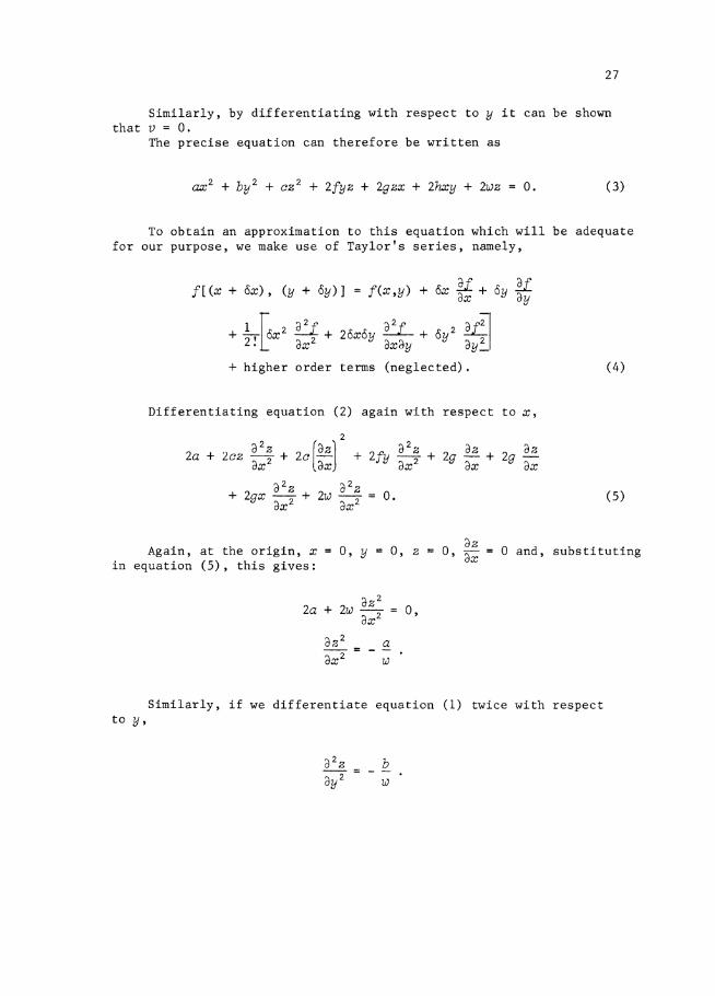
Similarly, by differenttating with respect to y it can be shownthat V = 0.
The precise equation can therefore be written as
ax 2 + by 2 + cz 2 + 2fyz + 2gzx + 2hxy + 2wz 0. (3)
To obtain an approximation to this equation which will be adequatefor our purpose, we make use of Taylor's series, namely,
f[ (x + ox), (y + 8y)]
+ 21,f6x2 32f +·t dX
+ higher order
f (x,y) + cSx li + oy lidX 'dy
28x8y~ + 8y 2 ~IdXdY dY~
terms (neglected). (4)
Differentiating equation (2) again with respect to x,
(5)
Again, at the orlg1n, xin equation (5), this gives:
0, y 0, ZdZ
0, dX = 0 and, substituting
dZ 2
2a + 2w -- = 0,dX 2
aw
Similarly, if we differentiate equation (1) twice with respectto y,

28
Differentiating equation (2) with respect to y,
(6)
At the origin, x = 0, y ; 0, Zsubstituting in equation (6),
0, dZ/ay = 0, and dZ/dX ~ 0 and
Substituting now in Taylor's series, equation (4), and regardingZ as f(x,y) ,
f[ (x + ox), (y + oy») = z f(O,O) + x ~: + y ~;
+ ~! E:~:z + 2a;~:Z + y ~:~,
hence
and may then be written as
( 7)
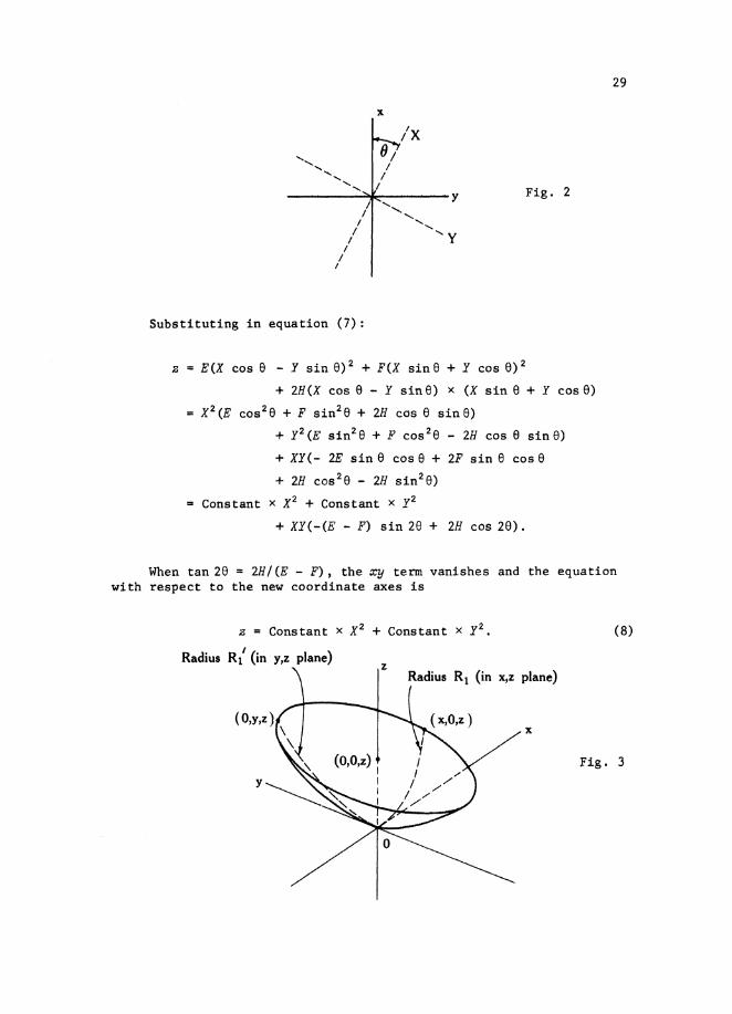
If z is constant (i.e. in any given plane parallel to the xy plane),equation (7) is an ellipse with its principal axes fotated with respectto the coordinate axes (see Fig. 2). If now the coordinate axes arealigned with the principal axes the xy term will vanish.
To do this, make the transformation:
x = X cos e - Y sin e ,
y = X sin e + Y cos e ,
where the angle e is given by tan 28 = 2H/ (E - F).
29
x
____-..o/............_, y
/ ..........
I ..............1/ ....... Y
I/
I
Substituting in equation (7):
Fig. 2
z = E(X cos 8 - Y sin 8)2 + F(X sinS + Y cos 8)2
+ 2H(X cos e - Y sine) x (X sin e + Y case)
= X2 (E cos 2 e + F sin2 e + 2H cos e sin8)
+ y 2 (E sin2 a + F cos 2 e - 2H cos 8 sinS)
+ XY(- 2E sin e cos e + 2F sin e cos 8
+ 28 coa 2 S - 2H sin2 e)
Constant x X2 + Constant x y2
+ XY(-(E - F) sin 28 + 28 cos 28),
When tan 28 = 2H/(E - F), the xy term vanishes and the equationwith respect to the new coordinate axes is
z = Constant x X2 + Constant x y2,
Radius R1' (in y,z plane)
o
(8)
Fig. 3

30
It is now necessary to determine these constants in equation (8) interms of a dimension or dimensions of the respective bodies.
Let R1 and R~ be the principle radii of curvature of one of thebodies (see Fig. 3); writing equation (8) in the form
z = Ax 2 + By2. (9)
Then, in the plane y = 0, we have Ax2 = z. Assuming circular curvaturein the plane y = 0, which is permissible in view of the magnitude of z,then,
Ignoring the second-order term of the small quantity z,
x2
Z = 2R •1
Since also
Similarly,
A
B
12R 1 •
12R' •1
We can, the.refore, now write the equations for the two bodies bysubstituting in equation (9):
(10)
and
(11)
VI' V~ and D2 , D~ being twice the principal radii of curvature of thetwo bodies respectively.

31
To obtain the compression effect between the two bodies, i.e.their mutual approach under an applied force, it is necessary totransform the coordinate axes of the two bodies (which so far havebeen treated as independent) to a single coordinate system withdifferent signs for the z-axes and then combine equations (10) and(11) •
Let the new common coordinate axes (normal to the z-axes) be(X,Y) , making angles 81 and 62 with the independent axes Xl and x
2respectively, such that 61 + 82 = w (see Fig. 4).
y
w------~---+---+-x
Fig. 4
Then the transformation of coordinates is given by the equations:
Xl X cos (31 y sin S1,
Y1 X sin Sl + y cos (31 '
x 2 X cos f3 2 + y sin (32'
Y2 -X sin 82 + y cos 82 •
Substituting in equations (10) and (11) we now have, in thecoordinate system (X ,y),
Z1 A1 (X cosS l - Y 8in(31)2 + B 1 (X sinSI + Y COSSl)2, (12)
Z2 A2 (X cos!32 + Y sin(2)2 + B 2 (-X sinS2 + Y cos(2)2.(13)
These two equations may be combined with a single equation, as allthese coordinate systems (X 1Yl)' (X 2Y2) , and (XY) have a common z-axisbut with different signs. Adding equations (12) and (13) and expandingthe bracket terms gives

32
21
+ 2 2 = X2 (A1
COS2S
1+ A2 COS
2S2 + B1
sin2S1 + B2 sin2( 2)
+ 2XY( -AI COS 81 sin (31 + B 1 sin S1 cos (31 + A2 cos 82 sin 82
- B2 sin 82 cas ( 2 )
+ y2(A 1 sin2 S1 + A 2 8inl82 + B 1 cosl81
+ B2 cos 2 Sl ). (14)
Now writing the coefficients of Xl and y 2 as A and B:
and
Adding,
(15)
Subtracting,
A - B A1 cos 281 - B 1 cos 28 1 + A2 cos 262 - B2 cos 28 2
(AI - B1 )cos 28 1 + (A 2 - B2 )cos 28 2 • (16)
Equation (14) would be further simplified if the cross-product term inXY could be made to vanish. This will be achieved if the coefficientof XY is equal to zero, namely,
i.e. o.
Squaring this equation gives
(AI - B1)28in2281 - 2(A 1 - B 1) (A 2 - B2 )sio 2(31 sin 28 2+ (A
2- B2 )2 sin22(32 = o. (17)

33
If we square equation (16) we have
(A - B)2 == (AI - Bl)2COS22S1 + 2(A 1 - B l )(A 2 - B 2 )cos 2S l cos 282
+ (A 2 - B2)2COS22B2. (18)
Adding equations (17) and (18) then gives
since (2S 1 + 2S2 ) = 2w.Equation (14) may therefore be rewritten as
(20)
where
1 1 1 1A + B == Tz + 75' + Tz + 75' ' (21)
1 122
w • angle between the original x-axes of the two bodies.
(0) Equations for Area of Contact,Pressupe Distribution, and Compression*
When two bodies are pressed together, displacements will occur inboth: in this case, we are considering forces operating parallel tothe z-axis, and displacements along this axis.
If the displacements at a point are WI and w2 ' then for pointsinside the area of contact, since the bodies touch over this area,
while, outside the area of contact,
*The argument here is essentially that of Landau and Lifshitz (1959).

34
a being the value of (WI + w2 ) at the or~g~n; i.e. a is the compressionwe are seeking. The distribution of the bodies is illustrated byFigure 5.
Applied force
~Surface 1
Fig. 5
Surface 2
Applied force
Having chosen the axis such that
(i.e. equation (20)), it follows that
a. (23)
Let the component of the pressure at a point (x~y') on the surfaceof contact be p(x~y')~ It can be shown (see for example Prescott 1924,pp. 623-7) that, assuming the surface to be plane, the deformation ata point (x,y) owing to this pressure is given by
W(X,y) p (x ~ y ') dx' dy',11
where r is the distance from the point (x,y) to the point (x~y').
Further, using the superposition theorem, the displacement at a point(x,y) due to the distribution of pressure over an area A is given by
w(x,y) (24)
35
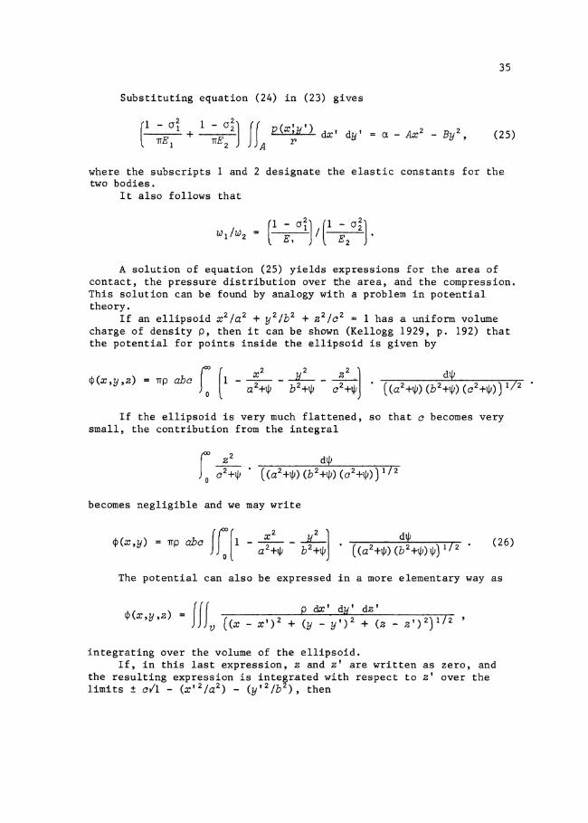
Substituting equation (24) in (23) gives
(1 -cri +_l_-_a_~J If p(x:y') dx' dy'
TIE 1 TIE2 A ra - Ax2
- By 2, (25)
where the subscripts 1 and 2 designate the elastic constant.s for thetwo bodies.
It also follows that
A solution of equation (25) yields expressions for the area ofcontact, the pressure distribution over t.he area, B:ndthe compression.This solution can be found by analogy with a problem in potentialtheory.
If an ellipsoid x2/a 2 + y2/b2 + Z2/a2 =: 1 has a uniform volumecharge of density P, then it can be shown (Kellogg 1929, p. 192) thatthe potential for points inside the ellipsoid is given by
¢(x,y,z) TIp abo
If the ellipsoid is very much flattened, so that 0 becomes verysmall, the contribution from the integral
becomes negligible and we may write
The potential can also be expressed in a more elementary way as
¢(x,y,z) JJt (x -e dx' qy' dz'
X')2 + (y _ y,)2 + (z _ Z')2)1/2 '
integrating over the volume of the ellipsoid.If, in this last expression, z and z' are written as zero, and
the resulting expression is inte~r~ted with respect to z' over thelimits ± 011 - (X'2/a2) - (y'2/b ), then

361/2
~(X.y) = 2pa II (1 - ~:2 _~~2) . d:1:'rdY ' • (27)
where p = (x - X')2 + (y _ y')2)1/2.Equation (27) then refers, as does equation (26), to the case of
an ellipsoid very much flattened in the a-direction, and the two maybe equated, giving
Comparing equations (25) and (28), it will be seen that, if theright-hand sides are viewed as quadratics in x and y, they haveidentical forms, while the left-hand sides are integrals of the sameform. It follows that the area of contact is bounded by the ellipsex 2 /a 2 + y2/b2 = 1. and that the pressure distribution over the area ofcontact is given by
Equating the integral Is p(x,y) ax dy to the total force, P,tending to compress the two bodies,
k 3P/2Tfab
and
x2 2 1/2p(x,y) = (3P/2nab) (1 - 2" -liT) ·
a b(29)
Substituting equation (29) in equation (25), and using equation (28)
a. ... Ax 2- By 2 , (30)
where VI = (1 - Of}/TIE1 and V2 = (1 - cr~)/TIE2.As this expression must hold for all values of x and y within the
contact ellipse, expressions for a, A, and B can be obtained by equatingcoefficients on both sides of (30), leading to:

37
3V
2) ( dt/J (31)a. = - P(V + (a 2+lJJ)·(b 2 +lJJ) lJJ) If 2
,4 1
A =1 P(V + V2
) ( dt/J (32)4 1 (a 2 +1JJ) (a 2+1lJ) (b 2+tJ;)lJJ) 1!2,
B 3 + V2 ) ( dllJ (33)= "4 P(V1 (b 2+1JJ) (a 2 +1JJ) (b 2+tJ;) lJJ) 1/2
The quantities a and b appear in the expression for a. as parametersand are in general unknown, and are determined from equations (32) and(33). These expressions are then used to obtain a and b from knownvalues of A and B.
III. SPECIAL CASES
(a) Two Spheres in Contact
If the spheres have diameters D1 and D2 respectively, then fromequations (10) and (11), we have:
and the area of contact is a circle (very flattened sphere) and a = b.By adding the above equations, we have
2 1 1 2(1 1)2 1 + 2 2 = X (- + -) + Y -D + D ·
D1 D2 1 2
Comparing this equation with equation (20), it follows that
A
Then equations (32) and (33) become identical and may be written
Putting tlJ1/2 = p, we can write

38
A = B
Therefore
Equation (31) gives the total compression in this case as
Again putting ~1/2 p, we can write
a = t P(V1 + V2 ) r 2dpo a2 + p2
= 31T P ( V + V2).
4a 1
Substituting for a, we then have
(b) Sphere in Contact with a PZane
This can be considered as two spheres in contact, the diameter ofone sphere being infinite.
The formula for a then becomes
(c) Sphere in Contact with an InternaZ Sphere
If the diameter of the internal sphere is D1
and the diameter ofthe small sphere is D
2then the situation is similar to that in III (b)
except that in the coordinate system adopted, the diameter of theinternal sphere becomes negative, giving

39
(d) Equal Cylindeps Crossed at Right Angles
Since two of the curvatures are equal and two are infinite, wecan write equations (10) and (11) as:
i.e.
A_ 1
B- V ·
From similar derivation to that given in III (b) , we therefore have
(e) Unequal Cylinders Crossed at Right AngZes
If the diameters of the two cylinders be D and D respectively,then, if their axes are at right angles, equati~ns (101 and (11) become:
t!-O + D '
2
i.e.
1A = D'
1
B 1=v;Now the equations connecting stress and strain, i.e. equations (31),
(32), and (33), can be expressed in terms of the eccentricity e of theellipse of contact 1 - e 2 = h2 /a 2 •
Considering equation (32), if we multiply the top and bottom linesof the integral by (l/a 2 )5/2 we have

40
Writing ~/a2 = ~ the equation becomes
i.e.
Similarly, it can be shown that equations (31) and (33) may bewritten:
These equations can be simplified by a further change of variable,
namely, by putting ~ = cot 2 e where e goes from into 0 as ~ goes fromo to 00. Then
dZ; == -2 cot e cosec 2 8 • de.

Substituting in the equation for Aa 3 we then have:
2
and, by reversing limits and sign,
Similarly it can be shown that
1!.3 J2 sin2 e de
Ba 3 = -2 P(V1 + V2 )(1 - e 2 sin2e)3/2 'o
Now the complete elliptic integral of the first class, K, is
41
K=
and
dK- = ede

42
Also the complete elliptic integral of the second class, E, is
and
dEde = -e
The equations can therefore be written in terms of the complete ellipticintegrals thus:
dEde '
dKde '
3where Q =4 (VI + V2 )·
These equations may be combined to give a compression equationindependent of a, namely,
1 13a = 2K(PQ)2/3( 1] .
2D (_ 1- dE)1 e de
Now the relationships connecting E and K are:
dE 1 (E _ K)de = e
and
from which we have

43
1 dE 1 (E _ K)e de = ~
and
Therefore, for any chosen value of e we can give the correspondingA 1 dE
values of B ' K, and - e de ·
Sets of such values are given in Appendix II.
(f) UnequaZ Diameter CyZinders Crossed withTheir Axes at Any Angle
This case differs from that of III(e) only in that the anglebetween the axes of the cylinders, 8, is some other value than 90°.
It is therefore necessary to obtain the ratio AlB by solving thefollowing equations (cf. equations (21) and (22» for A and B:
1 1A+B=-+-,DI D2
8 being the acute angle between the cylinder axes, and DI and D2 beingthe diameters of the larger and smaller cylinders respectively. Thegeneral formula for the compression is
1 13a = 2K(PQ) 2/3 ( A )
2 _ 1. dE· e de
(g) Sphere on a Cy linder
Since one diameter of the cylinder has become infinite,equations (10) and (11) become:
for the sphere,
for the cylinder,
where DI = diameter of the sphere,D2 diameter of the cylinder,
44
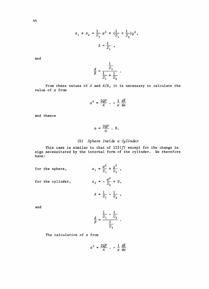
1 2 1 1 2ZI + Z2 = - X + (-D + -D)Y ,
D1 1 2
1A = D'
1
and
From these values of A and AlB, it is necessary to calculate thevalue of a from
and thence
a = 2QP • K.a
(h) Sphere Inside a Cylinder
This case is similar to that of III (f) except for the change insign necessitated by the internal form of the cylinder. We thereforehave~
for the sphere,
for the cylinder,
and
_ x 2 liZI - D + D '
1 1
All= IJ; - D2
'
The calculation of a from

45
and a from
ex = 2QP • Ka
then follow.
(i) Cylinde~s in Contaot along a Line Parallel toTheir Axes and a Cylinder on a Plane
It is not possible to obtain the solution by direct use of theexpressions already derived by allowing one axis of the ellipse ofcontact to become infinite as the solution itself then becomes infinite.This may appear surprising at first but the reason lies in the fact thatthe analysis requires the bodies to be fixed at infinity and this leadsto an infinite displacement. Prescott (1924) has likened the situationto a load applied to an infinitely long string fixed at one end. Theextension of such a string on the application of any load would beinfinite.
In determining the pressure distribution and the breadth of thearea of contact we shall make use of expressions obtained by allowingone axis of an ellipse of contact to become infinite. For the remainder,the contact area will be taken as being a finite rectangle but with oneside very much longer than the other.
The derivation given will be for the case of a pair of cylindersin contact with their axes parallel. The solution for a cylinder ona plane is then obtained by allowing the radius of one of the cylindersto become infinite.
It will be remembered that the pressure distribution over theellipse of contact in the three-dimensional case is given by
3Pp(x,y) = 27Tab
The integrated pressure across the minor axis of the ellipse inthe plane x = 0 is then
If ~oth a and P approach infinity in such a way that Pia remainsfinite, P is the force per unit length along the area of contact, whichis now rectangular with one side infinite.

46
It follows that
p(y)
1/2
(3P/2~ab) (1 - ~]1/2
2P ( 2]=- l_lLrrb b2
In the region of the original line of contact the cylinders areadequately represented by the surfaces:
The cylinders are initially in contact over a line of length 2a.Applying equation (25),
dy' a - By2, (34)
where r 2 = (y - y')2 + X'2 and the integral extends over the region ofcontact, which is taken to be a finite rectangle but with one side verymuch longer than the other. We are considering here only points lyingalong the y-axis. The assumption that one side of the rectangle, 2a,is very much longer than the other, 2b, allows the integral in the lefthand side of (34) to be evaluated.
Write
~(O,y) IfA p(y')/r dx' dy'
.. r: cp(y')/(X'2 + (y - y')2)1/2dx' dy'
.. rb2p (y ') fa 1/ (x' 2 + (y _ y') 2) 1 / 2dx ' dy'
J-b 0
.rb 2p (y ') 1n (a + (y - li') 2,+ a2) 1/2) dY'.
J-b Iy - y I
If now a is considered to be large in comparison with (y - y')
~(O,y) .. rb2p(y') 1n (2a/ly - y'l) dy'
J-b

47
and
¢(O,O) = 2(ln 2a) f+b p(y')dy' - f+b p(y') In (y')2dy',-b -b
where we are now restricted to the point (0,0).
Now f+b p(y')dy' = P, the force per unit length and-b
¢(O,O) [
b 1/2
2P In 2a - (2P! Tfb ) -b (1 - ~ ~ 2) In (y') 2dy' .
It remains then to determine the breadth of the area of contactand to evaluate the integral.
From equations (25) and (28),
using p(y)
B (VI + V2)P ( (b2 + 1/J~~721/J172- 22(V1 + V2 )Plb ,
i.e.
Turning now to the evaluation of the integral

48
Write y/b sin e" then dy = b cos e de giving
I = b
Now
and
so that
+2!. +1T
2b In b L~ cos 2 e de + 2b L~ cos 2 e In Isinslde.
2 2
]I
L~ cos2e In Isin elde - *(l + In 4) ,*
2
1 + 1n2
Substitution then leads to
~(O,O) = 2P(ln 2a + (1 + In 4)/2 - In b),
which in turn gives
a = 2P(V1 + V2 )[(1 + In 4)/2 + In 2a - In b].
The form of the expression for the compression of a pair ofcylinders with their axes parallel and for a cylinder on a plane isidentical. The compressions are then given by substituting theappropriate value for b in each case.
*Birens de Haan (1957), [305]8.

49
Pair ,of Cylinders with Their Axes Parallel:
Therefore
giving
Cy linder on a Flat:
giving
1B=15'
so that
IV . REFERENCES
Airey, J.R. (1935).-Toroidal functions and the complete ellipticintegrals. Phil. Mag. (7) ~, 177.
Berndt, G. (1928).-Die Akplattung-von Stahlkugeln und zylindern durchden Messdruck. (The compression of steel spheres and cylindersby measurement-pressure). Z. Instrumkde 48, 422.
Bierens de Haan, D. (1957).-''Nouvelles Tables d'Integrales Definies."(Hafner: New York.)
Hertz, H. (1881).-On the contact of elastic solids. J. peine angew.Math. 92, 156. In English translation: Hertz, H. (1896)."Miscellaneous Papers. tr p. 146. (Macmillan: New York.)

50
Kellogg, O.D. (1929).-"Foundations of Potential Theory." (Murray:New York.)
Landau, L.D., and Lifshitz, E.M. (1959).-"Theory of Elasticity."(Pergamon: London.)
Love, A.E.H. (1892).-"A Treatise on the Mathematical Theory ofElasticity." (Cambridge Univ. Press) (Dover: New York, 1944.)
Love, E.R. (1942).-Compression of elastic bodies in contact.Unpublished report, Defence Standards Laboratory, Australia.
Lubkin, J.L. (1962).-"Handbook of Engineering Mechanics." (Ed.W. Flugge.) Ch. 42. (McGraw-Hill: New York.)
Lur'e, I. (1964).-"Three-dimensional Problems of the Theory ofElasticity." (Interscience Publishers: New York.)
Perard, A., and Maudet, L. (1927).-Annexe II. Deformation au contact.Verification experimentale de la formule de Hertz. Trav. Mem.Bur. int. Poids Mes. lI, 76.
Poole, S.P. (1962).-New method of measuring the diameters of balls toa high precision. Machinery, Lond. 101, 904.
Prescott, J. (1924) .-"Applied Elasticity.-"-(Longmans Green: London.)(Dover: New York, 1961.)
Rolt, F.H., and Grant, C.R. (1921).-Elastic compression of spheresand cylinders. Unpublished report 1921, Metrology Department,National Physical Laboratory, Teddington, U.K.
Shtaennan, I.Ya. (1949).-"Kontaktnaya Zadacha Teori! Uprugosti."(The contact problem of the theory of elasticity). (Gos. izd.tekhn.-teoret. lit.: Moscow, Leningrad.)
Thomas, H.R., and Hoersch, V.A. (1930).-Stresses due to the pressureof one elastic solid upon another. Bull. Ill. Univ. Engng Exp.Stn No. 212.
AdditionaZ Reference: A paper dealing with compression effects inthin-walled cylindrical shells has been published recently -
Scarr, A.J., and Spence, A.R. (1968).-The effect of stylus pressureon the deformation and deflection of hollow cylindrical workpieces.Mioroteanic l1, Part I 130-3, Part II 220-5.

S1
APPENDIX I
Tables of Elastic Constants and Derived Quantities
The values for the elastic constants given in Tables 1 and 2 areintended as a guide to the values to be expected. The actual valuesof the constants for a material are dependent on its precise compositionand past history and are affected by such things as heat treatment andthe method of fabrication. The values given, however, should be adequatefor the calculation of compressions in most practical cases, as thepercentage error in a calculated compression due to an error ina constant is of the same order as the percentage error in the constant.The formulae derived here do not necessarily apply to anisotropicmaterials, in particular to crystals where the elastic properties maybe significantly different for different axes.

TABLE 1
Elastic Constants in Metric Units
Young's Modulus Young's Modulus Poisson's RatioMaterial E E CJ Source*
(10 10 Newtons/m2 ) (10 6 gf/nun2)
Aluminium 7.05 7.19 0.345 K & LCopper 13.0 13.24 0.343 K & LGold 7.8 8.0 0.440 K & LPlatinum 16.8 17.13 0.377 K & LSilver 8.28 8.43 0.367 K & LTungsten carbide
% Co6 72.4 73.8 0.280 A.S.M.
10 60.0 61.2 0.20016 52.4 53.4 0.220
Chromium carbide(Carmet CA-815G) 33.9 34.6 0.280 Carmet
Steel1% C 20.9 21.4 0.293 K & LMild 21.0 21.4 0.291 K & L
GlassPyrex 6.2 6.3 0.24 A.I.P.Heavy silicate flint 5.35 5.46 0.224 A.I.P.Light borate crown 4.61 4.70 0.274 A.I.P.
Brass70% Cu, 30% Zn 10.4 10.6 0.374 A.I.P.
Silica (fused) 7.29 7.43 0.17 A.I.P.
V1N
*A.I.P.K & LA.S.M.Carmet
American Institute of Physics Handbook: 2nd Edition.Kaye & Laby "Physical & Chemical Constants": 12th Edition (1959).A.S.M. Handbook: 8th Edition, 1961, p. 664.Allegheny Ludlum Steel Corporation.

TABLE 1 (Cont'd)
Elastic Constants in Metric Units
----------- in terms of gf/mm2
(l-a 2 )IE (1-a 2 ) IE) 2/3 V = (I-a 2) / TIE Q2/3 = (1 V) 2/3
Material 2
( 10- 7 ) (10- 5 ) (10- 8 ) (10- 5 )
Aluminium 1.225 2.467 3.901 1.507Copper 0.667 1.644 2.122 1.004Gold 1.014 2.174 3.227 1.328Platinum 0.501 1.359 1.594 0.830Silver 1.026 2.192 3.266 1.339Tungsten carbide
% Co6 0.125 0.538 0.397 0.329
10 0.157 0.627 0.500 0.38316 0.178 0.682 0.567 0.417
Chromium carbide(Carmet CA-815G) 0.266 0.892 0.848 0.545
Steel1% C 0.427 1.221 1.359 0.746Mild 0.427 1.222 1.361 0.747
GlassPyrex 1.491 2.811 4.745 1.717Heavy silicate flint 1. 741 3.118 5.542 1.905Light borate crown 1.968 3.383 6.263 2.067
Brass70% eu, 30% Zn 0.811 1.874 2.582 1.145
Silica (fused) 1.306 2.575 4.158 1.573
V1W

TABLE 2
Elastic Constants in lbf/in2
Young's Modulus Poisson's RatioMaterial E a Source*
(10 6 lbf/in2)
Aluminium 10.22 0.345 K & LCopper 18.83 0.343 K & LGold 11.3 0.44 K & LPlatinum 24.37 0.377 K & LSilver 12.00 0.367 K & LTungsten carbide
% Co6 105 0.28 A.S.M.
10 87 0.2016 76 0.22
Chromium carbide(Cannet CA-815G) 49.2 0.28 Carmet
Steel1% C 30.5 0.293 K & LMild 30.5 0.291 K & L
GlassPyrex 9.0 0.24 A.I.P.Heavy silicate flint 7.76 0.224 A.I.P.Light borate crown 6.69 0.274 A.I.P.
Brass70% Gu, 30% Zn 15.1 0.374 A.I.P.
Silica (fused) 10.57 0.17 A.I.P.
In+:'"
*A.I.P.K & LA.S.M.Carmet
American Institute of Physics Handbook: 2nd Edition.Kaye & Laby "Physical & Chemical Constants": 12th Edition (1959).A.S.M. Handbook: 8th Edition, 1961, p. 664.Allegheny Ludlum Steel Corporation.

TABLE 2 (Cont'd)
Elastic Constants in lbf/in2
(1-o 2 )IE ( (1-02 ) / E) 2/3 V = (1-02) /TTE Q2/3 = (1 V)2/3
Material 2
(10-8 ) (10- 5 ) (10-8 ) (10- 5 )
Aluminium 8.616 1.951 2.742 1.192Copper 4.687 1.300 1.492 0.794Gold 7.128 1.719 2.269 1.050Platinum 3.521 1.074 1.121 0.656Silver 7.214 1.733 2.296 1.059Tungsten carbide
% Co6 0.878 0.426 0.279 0.260
10 1.103 0.496 0.351 0.30316 1.252 0.539 0.399 0.329
Chromium carbide(Carmet CA-815G) 1.873 0.705 0.596 0.431
Steel1% C 3.001 0.966 0.955 0.590Mild 3.005 0.967 0.957 0.590
GlassPyrex 10.48 2.223 3.336 1.358Heavy silicate flint 12.24 2.465 3.896 1.506Light borate crown 13.83 2.675 4.403 1.634
Brass70% Cu, 30% Zn 5.702 1.481 1.815 0.905
Silica (fused) 9.184 2.036 2.923 1.244
VIV1

56
APPENDIX II
1 dEValues of K, - e de ' and Eccentrioities for Arguments AlB
The values given for the complete elliptical integral of the first
type, K, and the quantity - 1.. ddE have been derived from a number ofeesources. Tables 3-6 for AlB in the range 0.01 to 1.00 are due to Roltand Grant (1921), while the values given in Figure 6 have been derivedusing expressions given by Airey (1935). Both these series of valueshave been point-checked against a digital computer program based onthe method of the arithmetic-geometric mean. The curve of (1 - e 2
),
Figure 7, has been derived from the relationships that exist betweenAlB, K, and E.
TABLE 3
AlB [1.00(0.01)0.50]
A K 1 dE A K 1 dEB - e de B - e, de
1.00 1.5708 0.7854 0.75 1.7249 0.90370.99 1.5761 .7894 74 1.7322 .9095
98 1.5814 .7934 73 1.7397 .915397 1.5868 .7974 72 1.7472 .921396 1.5922 .8015 71 1.7549 .9274
0.95 1.5978 0.8057 0.70 1.7628 0.933694 1.6034 .8100 69 1.7707 .939993 1.6090 .8142 68 1.7788 .946392 1.6148 .8186 67 1.7870 .952991 1.6206 .8230 66 1.7953 .9595
0.90 1.6264 0.8275 0.65 1.8038 0.966489 1.6324 .8320 64 1.8125 .973388 1.6384 .8367 63 1.8213 .980487 1.6445 .8413 62 1.8302 .987686 1.6507 .8461 61 1.8393 .9949
0.85 1.6570 0.8509 0.60 1.8486 1.002584 1.6634 .8558 59 1.8581 1.010183 1.6698 .8608 58 1.8677 1.018082 1.6764 .8659 57 1.8775 1.026081 1.6830 .8710 56 1.8876 1.0341
0.80 1.6897 0.8762 0.55 1.8978 1.042579 1.6965 .8815 54 1.9082 1.051178 1.7035 .8869 53 1.9188 1.059877 1.7105 .8924 52 1.9297 1.068876 1.7176 .8980 51 1.9408 1.0779
0.50 1.9521 1.0874
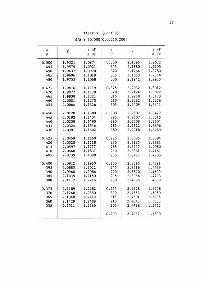
TABLE 3 (Cont'd)
AlB: [0.500(0.005)0.200]
A K 1 dE A K 1 dEIf - e de B - e de
0.500 1.9521 1.0874 0.350 2.1595 1.2632495 1.9579 1.0921 345 2.1680 1.2705490 1.9637 1.0970 340 2.1766 1.2780485 1.9696 1.1019 335 2.1853 1.2856480 1.9755 1.1068 330 2.1942 1.2933
0.475 1.9816 1.1119 0.325 2.2032 1.3012470 1.9877 1.1170 320 2.2124 1.3092465 1.9938 1.1221 315 2.2218 1.3173460 2.0001 1.1273 310 2.2312 1.3256455 2.0064 1.1326 305 2.2409 1.3341
0.450 2.0128 1.1380 0.300 2.2507 1.3427445 2.0192 1.1434 295 2.2607 1.3515440 2.0258 1.1490 290 2.2709 1.3604435 2.0324 1.1546 285 2.2812 1.3696430 2.0391 1.1602 280 2.2918 1.3789
0.425 2.0459 1.1660 0.275 2.3025 1.3884420 2.0528 1.1718 270 2.3135 1.3981415 2.0597 1.1777 265 2.3247 1.4080410 2.0668 1.1837 260 2.3361 1.4181405 2.0739 1.1898 255 2.3477 1.4285
0.400 2.0812 1.1960 0.250 2.3595 1.4391395 2.0885 1.2022 245 2.3716 1.4499390 2.0960 1.2086 240 2.3840 1.4609385 2.1035 1.2150 235 2.3966 1.4723380 2.1112 1.2216 230 2.4096 1.4839
0.375 2.1189 1.2282 0.225 2.4228 1.4958370 2.1268 1.2350 220 2.4363 1.5080365 2.1348 1.2419 215 2.4501 1.5205360 2.1429 1.2489 210 2.4643 1.5333355 2.1511 1.2560 205 2.4788 1.5465
0.200 2.4937 1.5600
57

58
TABLE 4
AlB [0.200(0.001)0.100]
A K 1 dE A K 1 dEB - e de B - e de
0.200 2.4937 1.5600 0.175 2.5745 1.6337199 2.4968 1.5627 174 2.5779 1.6369198 2.4998 1.5655 173 2.5814 1.6401197 2.5029 1.5683 172 2.5849 1.6433196 2.5059 1.5711 171 2.5885 1.6465
0.195 2.5090 1.5739 0.170 2.5920 1.6498194 2.5121 1.5767 169 2.5956 1.6531193 2.5152 1.5796 168 2.5992 1.6564192 2.5184 1.5824 167 2.6028 1.6597191 2.5215 1.5853 166 2.6064 1.6631
0.190 2.5247 1.5882 0.165 2.6101 1.6664189 2.5279 1.5911 164 2.6138 1.6698188 2.5311 1.5940 163 2.6175 1.6733187 2.5343 1.5970 162 2.6212 1.6767186 2.5376 1.5999 161 2.6250 1.6802
0.185 2.5408 1.6029 0.160 2.6287 1.6836184 2.5441 1.6059 159 2.6325 1.6871183 2.5474 1.6089 158 2.6364 1.6907182 2.5507 1.6119 157 2.6402 1.6942181 2.5541 1.6150 156 2.6441 1.6978
0.180 2.5574 1.6181 0.155 2.6480 1.7014179 2.5608 1.6211 154 2.6519 1.7051178 2.5642 1.6243 153 2.6559 1.7087177 2.5676 1.6274 152 2.6598 1.7124176 2.5710 1.6305 151 2.6639 1.7161

TABLE 4 (Cont'd)
AlB: [0.200(0.001)0.100]
A K 1 dE A K 1 dEB - e de B - e de
0.150 2.6679 1.7198 0.125 2.7786 1.8230149 2.6719 1.7236 124 2.7835 1.8275148 2.6760 1.7274 123 2.7884 1.8321147 2.6801 1.7312 122 2.7934 1.8368146 2.6843 1.7350 121 2.7984 1.8415
0.145 2.6885 1.7389 0.120 2.8034 1.8462144 2.6927 1.7428 119 2.8085 1.8510143 2.6969 1.7468 118 2.8136 1.8558142 2.7012 1.7507 117 2.8188 1.8607141 2.7054 1.7547 116 2.8240 1.8656
0.140 2.7098 1.7587 0.115 2.8293 1.8705139 2.7141 1.7628 114 2.8346 1.8755138 2.7185 1.7669 113 2.8399 1.8805137 2.7229 1.7710 112 2.8453 1.8856136 2.7274 1.7751 111 2.8508 1.8908
0.135 2.7319 1.7793 0.110 2.8563 1.8960134 2.7364 1.7835 109 2.8618 1.9012133 2,.7409 1.7878 108 2.8674 1.9065132 2.7455 1.7920 107 2.8731 1.9118131 2.7501 1.7964 106 2.8788 1.9172
0.130 2.7548 1.8007 0.105 2.8846 1.9226129 2.7595 1.8051 104 2.8904 1.9281128 2.7642 1.8095 103 2.8962 1.9337127 2.7690 1.8140 102. 2.9022 1.9393126 2.7738 1.8184 101 2.9082 1.9449
0.100 2.9142 1.9507
59

60
TABLE 5
AlB [0.100(0.001)0.050]
A K 1 dE A K 1 dEB - e de B - e de
0.100 2.9142 1.9507 0.075 3.0889 2.1171099 2.9203 1.9565 74 3.0970 2.1249
98 2.9265 1.9623 73 3.1053 2.132897 2.9327 1.9682 72 3.1136 2.140896 2.9390 1.9742 71 3.1221 2.1489
0.095 2.9454 1.9802 0.070 3.1307 2.157294 2.9518 1.9863 69 3.1394 2.165693 2.9583 1.9925 68 3.1483 2. 174192 2.9649 1.9987 67 3.1573 2.182791 2.9715 2.0050 66 3.1664 2.1915
0.090 2.9782 2.0114 0.065 3.1756 2.200489 2.9850 2.0179 64 3.1850 2.209488 2.9919 2.0244 63 3.1945 2.218687 2.9988 2.0310 62 3.2042 2.227986 3.0058 2.0377 61 3.2141 2.2374
0.085 3.0129 2.0445 0.060 3.2241 2.247184 3.0201 2.0513 59 3.2342 2.256983 3.0274 2.0583 58 3.2446 2.266982 3.0347 2.0653 57 3.2551 2.277081 3.0422 2.0724 56 3.2658 2.2874
0.080 3.0497 2.0796 0.055 3.2767 2.297979 3.0574 2.0869 54 3.2877 2.308678 3.0651 2.0943 53 3.2990 2.319577 3.0729 2.1018 52 3.3105 2.330776 3.0809 2.1094 51 3.3222 2.3420
0.050 3.3342 2.3536

TABLE 5 (Cont'd)
AlB [0.0500(0.0005)0.0200]
A K 1 dE A K 1 dEB - e de B - e de
0.0500 3.3342 2.3536 0.0350 3.5486 2.5626495 3.3403 2.3595 345 3.5573 2.5710490 3 .. 3464 2.3655 340 3.5660 2.5796485 3.3526 2.3715 335 3.5749 2,,5883480 3.3588 2,,3775 330 3.5839 2.5971
0.0475 3,,3651 2,,3837 0,,0325 3.5930 2.6060470 3.3715 2.3899 320 3.6023 2.6151465 3.3779 2.3961 315 3.6117 2.6244460 3.3845 2.4025 310 3.6213 2.6337455 3.3910 2.4089 305 3.6310 2.6433
0.0450 3.3977 2,,4153 0.0300 3.6409 2.6530445 3.4044 2.4219 295 3.6509 2.6628440 3.4112 2.4285 290 3.6611 2,,6728435 3,,4181 2.4352 285 3.6715 2,,6830430 3.4251 2.4420 280 3,,6821 2.6934
0.0425 3.4321 2.4488 0.0275 3,,6928 2.7039420 3,,4392 2.4558 270 3.7038 2,,7147415 3.4464 2.4628 265 3.7149 2,,7256410 3.4537 2.4699 260 3,,7263 2.7368405 3.4611 2.4771 255 3.7378 2.7482
0,,0400 3.4685 2.4843 0.0250 3,,7496 2.7598395 3.4761 2.4917 245 3.7616 2.7716390 3.4837 2.4992 240 3.7739 2.7837385 3.4915 2,,5067 235 3.7864 2.7960380 3.4993 2.5144 230 3.7992 2.8086
0,,0375 3.5073 2.5222 0.0225 3.8123 2.8215370 3,,5153 2.5300 220 3.8256 2.8346365 3,,5235 2.5380 215 3.8393 2.8481360 3.5318 2.5461 210 3.8532 2.8618355 3.5401 2,,5543 205 3.8675 2.8759
0.0200 3.8821 2.8903
61

62
TABLE 6
AlB [0.0200(0.0001)0.0100]
A K 1 dE A K 1 dEB - e de B - e de
0.0200 3.8821 2.8903 0.0175 3.9611 2.9683199 3.8850 2.8932 174 3.9644 2.9716198 3.8880 2.8962 173 3 .. 9678 2.9750197 3.8910 2.8991 172 3.9713 2.9784196 3.8940 2.9021 171 3.9747 2.9818
0.0195 3.8971 2.9051 0.0170 3.9782 2.9852194 3.9001 2.9081 169 3.9816 2.9886193 3.9032 2.9111 168 3.9851 2.9921192 3.9062 2 .. 9142 167 3.9887 2.9956191 3.9093 2.9172 166 3.9922 2.9991
0.0190 3.9124 2.9203 0.0165 3.9958 3.0026189 3.9156 2.9234 164 3.9994 3.0062188 3.9187 2.9264 163 4.0030 3.0097187 3.9219 2.9296 162 4.0066 3.0133186 3 .. 9250 2 .. 9327 161 4.0102 3.0169
0.0185 3.9282 2.9358 0.0160 4.0139 3.0205184 3.9314 2.9390 159 4.0176 3.0242183 3.9346 2.9422 158 4.0213 3.0279182 3.9379 2.9454 157 4.0251 3.0316181 3.9411 2.9486 156 4.0288 3.0353
0.0180 3.9444 2.9518 0.0155 4.0326 3.0391179 3.9477 2.9551 154 4.0364 3.0428178 3.9510 2.9584 153 4.0403 3.0466177 3.9543 2.9617 152 4.0441 3.0504176 3.9577 2.9650 151 4 .. 0480 3.0543

TABLE 6 (Cont'd)
AlB [0.0200(0.0001)0.0100]
A K 1 dE A K 1 dEB - e de B - e de
0.0150 4.0519 3.0582 0.0125 4.1590 3.1642149 4.0558 3.0620 124 4.1637 3.1689148 4.0598 3.0660 123 4.1684 3.1736147 4.0638 3.0699 122 4.1732 3.1783146 :4.0678 3.0739 121 4.1780 3.1831
0.0145 4.0718 3.0779 0.0120 4.1829 3.1879144 4.0759 3.0819 119 4.1878 3.1928143 4.0800 3.0860 118 4.1927 3.1977142 4.0841 3.0901 117 4.1977 3.2026141 4.0883 3.0942 116 4.2027 3.2076
0.0140 4.0925 3.0983 0.0115 4.2078 3.2126139 4.0967 3.1025 114 4.2129 3.2177138 4.1009 3.1067 113 4.2181 3.2228137 4.1052 3.1109 112 4.2233 3.2280136 4.1095 3.1152 111 4.2285 3.2332
0.0135 4.1138 3.1195 0.0110 4.2338 3.2384134 4.1182 3.1238 109 4.2391 3.2437133 4.1226 3.1282 108 4.2445 3.2491132 4.1270 3.1325 107 4.2499 3.2545131 4.1315 3.1370 106 4.2554 3.2599
0.0130 4.1360 3.1414 0.0105 4.2610 3.2654129 4.1405 3.1459 104 4.2666 3.2710128 4.1451 3.1504 103 4.2722 3.2766127 4.1497 3.1550 102 4.2779 3.2822126 4.1543 3.1596 101 4.2837 3.2879
0.0100 4.2895 3.2937
63

64
10
9
8
7
6
'5
4
'"f'....~ I I I JJ III
"'-,,- K=f2 1Io (1-e2 sin2 8)2
"- 1T
'" ~ _1. ~=12 sin2 IJd8~ 1
'" ~e de 0
(1-e2 sin2 8)'2~~ ~~ I
" """" ~K
f'~~ " '""""" ',,-
~~~
"~ ~~ I
'~~~
i'.~"
_l.(E!.)/~
I""""r'lle de ~
I'~'" " "-
i' __ ~ f',r--.. '-
"~
'-f'~
'-""
AlB
Fig. 6
10-2
0-003
0·002
0-001
./~
./~
V/
I'"
/~
V/
~
./~
V./
~
/'./
~
""./'~
V../
/~,."
VJJ11I""
~
0·001 0'002 0'003 0'004 0·005
AlB0·006 0·007 0·008 0'009 0·010
Fig. 7 - Eccentricity.