elastic and viscoelastic effects in rubber/air acoustic...
TRANSCRIPT

Elastic and viscoelastic effects in rubber/air acoustic band gap structures:A theoretical and experimental study
B. Merheb,1,a� P. A. Deymier,1 M. Jain,2 M. Aloshyna-Lesuffleur,2 S. Mohanty,2
A. Berker,2 and R. W. Greger3
1Department of Materials Science and Engineering, University of Arizona, Tucson, Arizona 85721, USA2Corporate Research Materials Laboratory, 3M Co., 3M Center, St. Paul, Minnesota 55144-1000,USA3Volt Services Group, Corporate Research Materials Laboratory, 3M Co., 3M Center, St. Paul,Minnesota 55144-1000, USA
�Received 6 January 2008; accepted 24 July 2008; published online 25 September 2008�
The transmission of acoustic waves through centimeter-scale elastic and viscoelastictwo-dimensional silicone rubber/air phononic crystal structures is investigated theoretically andexperimentally. We introduce a finite difference time domain method for two-dimensional elasticand viscoelastic composite structures. Elastic fluid-solid phononic crystals composed of atwo-dimensional array of cylindrical air inclusions in a solid rubber matrix, as well as an array ofrubber cylinders in an air matrix, are shown to behave similarly to fluid-fluid composite structures.These systems exhibit very wide band gaps in their transmission spectra that extend to frequenciesin the audible range of the spectrum. This effect is associated with the very low value of thetransverse speed of sound in rubber compared to that of the longitudinal polarization. The differencein transmission between elastic and viscoelastic rubber/air crystals results from attenuation oftransmission over a very wide frequency range, leaving only narrow passing bands at very lowfrequencies. These phononic crystals demonstrate the practical design of elastic or viscoelastic solidrubber/air acoustic band gap sound barriers with small dimensions. © 2008 American Institute ofPhysics. �DOI: 10.1063/1.2980330�
I. INTRODUCTION
During the past decade, numerous theoretical and experi-mental studies have focused on the propagation of elasticwaves in phononic crystals.1–6 Phononic crystals are com-posed of two-dimensional �2D� or three-dimensional peri-odic repetitions of some inclusions inside a matrix. The ma-trix and inclusions can be constituted of solids or fluids.Band gaps in the band structure and in the transmission spec-trum of phononic crystals form for large contrasts in theelastic coefficients and the mass densities of the matrix andinclusion materials. Acoustic band gap �ABG� structures,also called sonic crystals, are therefore phononic crystalswith band gaps in the acoustic range of frequencies. Sincethe band gaps result from Bragg scattering of the elasticwaves by the periodic array of inclusions, the lowest fre-quency at which a gap appears is therefore limited by thesize of the periodicity of the array of inclusions. Elastic fluid/fluid ABGs have been shown to possess band gaps at signifi-cantly lower frequencies than their solid/solid and solid/fluidcounterpart2 due in part to the absence of transverse polar-ization.
In spite of the extensive literature on elastic phononiccrystals, there is very little information concerning the prop-erties of phononic crystals composed of viscoelastic materi-als. There is a theoretical demonstration of the existence ofan absolute band gap in the transmission spectrum of a three-
dimensional sonic crystal composed of viscoelastic sphericalinclusions in air.7 In that study the viscoelastic medium wasmodeled with a simple Kelvin–Voigt model.
In this present paper we consider 2D elastic and vis-coelastic silicone rubber/air ABG structures. These are 2Darray of cylinders of air inclusions in a solid rubber matrix aswell as arrays of rubber cylinders in an air matrix. First, weinvestigate theoretically and experimentally the transmissionproperties of these ABG structures. We pay particular atten-tion to the transmission behavior in the audible range ofacoustic frequencies. Indeed the commercially available rub-ber studied here possesses a transverse speed of sound that isan order of magnitude, or more, smaller than the longitudinalspeed of sound. The longitudinal speed of sound in rubbers iscomparable to that of water and rubber/air phononic crystalsare expected to show behaviors similar to that of the well-known water/air structures that possess wide band gaps atvery low frequencies.2 We show that for the particular sili-cone rubber studied here, an elastic representation is suffi-cient for understanding the experimental spectrum. However,since many polymers and rubbers exhibit viscoelastic prop-erties, we have extended our theoretical study to include vis-coelasticity. While the moduli of linear elastic materials areindependent of frequency, linear viscoelastic materials havedynamic moduli that decrease with decreasing frequency.The mechanical response of viscoelastic materials will there-fore vary over time, providing a dissipative mechanism thatis absent in linear elastic materials. In this study, viscoelas-ticity is modeled with a compressible general linear vis-coelastic fluid �GLVF� model. Numerical calculations ofa�Electronic mail: [email protected].
JOURNAL OF APPLIED PHYSICS 104, 064913 �2008�
0021-8979/2008/104�6�/064913/9/$23.00 © 2008 American Institute of Physics104, 064913-1
Downloaded 10 Mar 2009 to 150.135.172.77. Redistribution subject to AIP license or copyright; see http://jap.aip.org/jap/copyright.jsp

transmission spectra are conducted by extending the finitedifference time domain �FDTD� method to account for time-dependent moduli. This viscoelastic FDTD method is intro-duced and described in detail in Sec. II. In the results, Sec.III, we show theoretically and experimentally that the elasticrubber/air ABG structures with centimeter dimensions ex-hibit very wide band gaps extending to low frequencies.These gaps result from the very large contrast between thelongitudinal and transverse speeds of sound in rubber. Thesilicone rubber-air systems, therefore, mimic the behavior offluid/fluid systems. Moreover we show theoretically that thetransmission properties of linear viscoelastic ABG materialsdiffer significantly from the behavior of linear elastic mate-rials. Viscoelasticity impacts the transmission spectrum byattenuating transmission within the passing bands of thestructure. The conclusions drawn from this joint experimen-tal and theoretical study are reported in Sec. IV.
II. METHODS AND MODELS
In the present study, we conduct FDTD calculations oftransmission spectra of elastic rubber-air phononic crystals.The FDTD method for elastic composite media is welldocumented8 and not described in this paper; however, wealso consider here theoretically the effect of the viscoelastic-ity on the transmission spectrum of phononic crystals. Forthis purpose we develop in detail in this section an efficientFDTD method that accounts for viscoelasticity within aMaxwell–Weichert model. We finally, describe the experi-mental method employed to measure transmission spectra ofrubber/air ABG structures.
A. Computational method
The elastic wave equation is given by
�v
�t=
1
�div � , �1�
where t is the time, � is the mass density, v�t� is the velocityvector, and � is the total stress tensor.
To calculate the stress tensor we employ the constitutiveequation for the GLVFs. The compressible generalized linearviscoelastic solid relation is properly invariant and obeys theprinciple of material objectivity. Furthermore, while there area myriad number of alternative, properly invariant, constitu-tive relations to choose from for nonlinear viscoelasticity, allof these must reduce to the generalized linear viscoelasticmaterial model in the linear viscoelastic limit. Since we areprimarily interested in linear acoustics that involve smallstrains, one is justified in restricting the material’s rheologi-cal behavior to be linear as well, in which case the onlyproperly invariant constitutive relation that one is justified touse is the generalized linear viscoelastic model.
When the GLVF material is compressible, the total stresstensor is given by
��t� = 2�−�
t
G�t − t��D�t��dt� + �−�
t �K�t − t�� −2
3G�t
− t����� · v�t���Idt�, �2�
where D�x , t� is the rate of deformation tensor given by
D = 12 ���v� + ��v�T� �3�
and G�t� and K�t� are the steady shear and bulk moduli,respectively. These moduli can be experimentally determinedthrough rheometry and the data can be fitted in a variety ofways, including the use of mechanical-analog models. A vis-coelastic model or in effect the behavior pattern it describesmay be illustrated schematically by combinations of springsand dashpots, representing elastic and viscous factors, re-spectively. Hence, a spring is assumed to reflect the proper-ties of an elastic deformation, and similarly a dashpot is as-sumed to depict the characteristics of viscous flow. Thegeneralized Maxwell, also known as the Maxwell–Weichert,model takes into account the fact that the relaxation does notoccur with a single time constant but with a distribution ofrelaxation times. The Weichert model shows this by havingas many spring-dashpot Maxwell elements as are necessaryto accurately represent the distribution �Fig. 1�. A multipleelement Maxwell model is therefore more apt to representthe numerous time scales associated with relaxation in realviscoelastic materials.
For an n-element generalized Maxwell solid model theextensional modulus E�t� is calculated to be
E�t� = E� + �i=1
n
Eie−t/�i, �4�
where Ei ,�i ; i=1,2 , . . . ,n are the moduli and relaxationtimes of the elements and E�=E��� is the equilibrium exten-sional modulus. We use the generalized Maxwell form forE�t� only as a convenient fit to our modulus data that weobtained by performing dynamic mechanical analysis�DMA� tests in extensional mode on a sample of a commer-cial silicone elastomer.
FIG. 1. �Color online� Spring and dashpot illustrations of the Maxwell–Weichert model.
064913-2 Merheb et al. J. Appl. Phys. 104, 064913 �2008�
Downloaded 10 Mar 2009 to 150.135.172.77. Redistribution subject to AIP license or copyright; see http://jap.aip.org/jap/copyright.jsp

By introducing ��t� as a function having the same formas E�t�:
��t� = �0 + �i=1
n
�ie−t/�i, �5�
where
�0 =E�
Esum, �i =
Ei
Esum�i = 1,2, . . . ,n�
and
�i=0
n
�i = 1, Esum = �i=1
n
Ei,
we obtain
E�t� = Esum��t� . �6�
Consequently, we assume that
E�t� = 2G�t��1 + �� = 3K�t��1 − 2�� , �7�
with
G�t� = Gsum��t� ,
K�t� = Ksum��t� �8�
and
Gsum = � ,
Ksum −2
3Gsum = � . �9�
In Eqs. �7� and �9�, is Poisson’s ratio and � and � arethe Lamé constant and shear modulus, respectively.
Now we consider a 2D elastic/viscoelastic material,where the system is infinite in the vertical direction z, andnone of its properties depends on z �translational invariance�.In this case the Cartesian components of the 2D stress tensorbecome
�xx�t� = 2�−�
t
G�t − t���vx
�x�t��dt� + �
−�
t �K�t − t��
−2
3G�t − t���� �vx
�x�t�� +
�vy
�y�t���dt�, �10�
�yy�t� = 2�−�
t
G�t − t���vy
�y�t��dt� + �
−�
t �K�t − t��
−2
3G�t − t���� �vx
�x�t�� +
�vy
�y�t���dt�, �11�
�xy�t� = �yx�t� = �−�
t
G�t − t��� �vx
�y�t�� +
�vy
�x�t���dt�.
�12�
For the sake of illustration, let us insert Eq. �8� into Eq.�10�. Using C11=2�+�, C12=�, and C44=�, �xx�t� become
�xx�t� = �0C11�ux
�x�t� + �0C12
�uy
�y�t�
+ C11�1
n
�i�−�
t �vx
�x�t��e−�t−t��/�idt�
+ C12�1
n
�i�−�
t �vy
�y�t��e−�t−t��/�idt�. �13�
The elastic behavior is recovered by setting �0=1 and�i=0 for i=1, . . . ,n �E�0 and Ei=0 for i=1, . . . ,n�.
The difficulty of the problem consists in the calculationof integrals of the type
Ixxi�t� = �−�
t �vx�t���x
e−�t−t��/�idt�. �14�
We show in the Appendix that Ixxi�t� can be calculatedby a recursive method:
Ixxi�t + dt� = �vx�t��x
e−dt/�i +�vx�t + dt�
�x
2�dt
+ e−dt/�iIxxi�t� , �15�
where Ixxi�0�=0.Similar equations are obtained for the yy and xy compo-
nents �see the Appendix�.We can now develop the FDTD method for the general-
ized Maxwell model. This involves transforming the govern-ing differential equations in the time domain into finite dif-ferences and solving them as one progresses in time in smallincrements. These equations comprise the basis for theimplementation of the FDTD in 2D viscoelastic systems. Forthe implementation of the FDTD method we divide the com-putational domain into Nx�Ny subdomains �grids� with di-mension dx, dy. For space derivatives we use central differ-ences, where the y direction is staggered to the x direction.For the time derivative we use forward difference, with atime interval dt.
Using expansions at point �i , j� and time �n�, Eq. �1� incomponent form becomes
vxn+1�i, j� = vx
n�i, j� +dt
��i, j���xx
n+1�i, j� − �xxn+1�i − 1, j�
dx
+�xy
n+1�i, j� − �xyn+1�i, j − 1�
dy� , �16�
vyn+1�i, j� = vy
n�i, j�
+dt
��i + 1/2, j + 1/2���yy
n+1�i, j + 1� − �xxn+1�i, j�
dy
+�xy
n+1�i + 1, j� − �xyn+1�i, j�
dx� , �17�
where
��i + 1/2, j + 1/2�
= �4 ��i, j���i + 1, j���i, j + 1���i + 1, j + 1� .
064913-3 Merheb et al. J. Appl. Phys. 104, 064913 �2008�
Downloaded 10 Mar 2009 to 150.135.172.77. Redistribution subject to AIP license or copyright; see http://jap.aip.org/jap/copyright.jsp

The stress component �xx is calculated by discretizingEq. �13�, using expansion at point �i , j� and time �n�, andincluding the recursive form of the integral from Eq. �15�:
�xxn+1�i, j� = �0�i + 1/2, j�C11�i
+ 1/2, j�ux
n�i + 1, j� − uxn�i, j�
dx+ �0�i
+ 1/2, j�C12�i + 1/2, j�uy
n�i, j� − uyn�i, j − 1�
dy
+ C11�i + 1/2, j��p=1
n
�p�i + 1/2, j�
��vxn�i + 1, j� − vx
n�i, j�2dx
+vx
n−1�i + 1, j� − vxn−1�i, j�
2dxe−dt/�p�i+1/2,j�
+ e−dt/�p�i,j�Ixxp
n � + C12�i + 1/2, j��p=1
n
�p�i
+ 1/2, j��vyn�i, j� − vy
n�i, j − 1�2dy
+vy
n−1�i, j� − vyn−1�i, j − 1�
2dye−dt/�p�i+1/2,j�
+ e−dt/�p�i,j�Iyyp
n � . �18�
We define
C11�i + 1/2, j� = �C11�i + 1, j�C11�i, j� ,
C12�i + 1/2, j� = �C12�i + 1, j�C12�i, j� ,
and
�p�i + 1/2, j� = ��p�i + 1, j��p�i, j�, p = 0,1,2, . . . ,n .
Similarly, the components �yy and �xy are obtained indiscretized form:
�yyn+1�i, j� = �0�i + 1/2, j�C11�i
+ 1/2, j�uy
n�i, j� − uyn�i, j − 1�
dy+ �0�i
+ 1/2, j�C12�i + 1/2, j�ux
n�i + 1, j� − uxn�i, j�
dx
+ C11�i + 1/2, j��p=1
n
�p�i + 1/2, j�
��vyn�i, j� − vy
n�i, j − 1�2dy
+vy
n−1�i, j� − vyn−1�i, j − 1�
2dye−dt/�p�i+1/2,j�
+ e−dt/�p�i,j�Iyyp
n � + C12�i + 1/2, j��p=1
n
�p�i
+ 1/2, j��vxn�i + 1, j� − vx
n�i, j�2dx
+vx
n−1�i + 1, j� − vxn−1�i, j�
2dxe−dt/�p�i+1/2,j�
+ e−dt/�p�i,j�Ixxp
n � , �19�
�xyn+1�i, j� = �0�i, j + 1/2�C44�i, j + 1/2�
��uxn�i, j + 1� − ux
n�i, j�dy
+uy
n�i, j� − uyn�i − 1, j�
dx� + C44�i, j
+ 1/2��p=1
n
�p�i, j + 1/2��vxn�i, j + 1� − vx
n�i, j�2dy
+vx
n−1�i, j + 1� − vxn−1�i, j�
2dye−dt/�p�i,j+1/2�
+ e−dt/�p�i,j�Ixyp
n � + C44�i, j + 1/2��p=1
n
�p�i, j
+ 1/2��vyn�i, j� − vy
n�i − 1, j�2dx
+vy
n−1�i, j� − vyn−1�i − 1, j�
2dxe−dt/�p�i,j+1/2�
+ e−dt/�p�i,j�Iyxp
n � , �20�
where
C44�i, j + 1/2� = �C44�i, j + 1�C44�i, j� ,
�p�i, j + 1/2� = ��p�i, j + 1��p�i, j�, p = 0,1,2, . . . ,n .
It has to be mentioned that the above way of discretizingthe equations ensures second order accurate central differ-ence for the space derivatives. The field components ux anduy have to be centered in different space points.
The FDTD method for elastic and viscoelastic media islocal in space and ideally suited for computer simulation onparallel platforms. All the calculations reported are per-formed on at least eight parallel processors.
B. Model structures
We study two model structures illustrated in Figs. 2 and3. These structures are composed of three separate regions.The central region is a phononic crystal modeled as arrays ofcylindrical inclusions with circular cross section made of iso-tropic material, embedded in an isotropic material matrix.The cylinders, with diameter d, are assumed to be parallel tothe Z axis of the Cartesian coordinates �OXYZ�. The array is
064913-4 Merheb et al. J. Appl. Phys. 104, 064913 �2008�
Downloaded 10 Mar 2009 to 150.135.172.77. Redistribution subject to AIP license or copyright; see http://jap.aip.org/jap/copyright.jsp

then considered infinite in the two directions X and Z andfinite in the direction of propagation of the probing wave �Y�.The periodicity along the direction X is ensured by the ap-plication of periodic boundary conditions. In Fig. 2�a� thematrix is made of rubber and the inclusions are made of air.In Fig. 2�b� the matrix is air and the cylinders are composedof rubber. For all calculations reported here, the physicalcharacteristics of the rubber are those of a polysilicone rub-ber with mass density=1260 kg /m3, longitudinal speed=1200 m /s, and transverse speed=20 m /s.9 The longitudi-nal speed of sound was measured in our laboratory by a timeof flight method �see Sec. II C�. We have not been able tomeasure reliably the transverse speed of sound; however, weestimate it to be �20 m /s from published data on physicalconstants with different rubbers.9 Air is modeled as a fluidwith mass density=1.3 kg /m3 and longitudinal speed=340 m /s. In Fig. 2�a� the air cylinders have a diameter of 8mm and are arranged on a 6�1 square array with a latticeparameter a=12 mm. The second structure represented inFig. 2�b� consists of an array of touching polymer cylinderslocated on a honeycomb lattice with a hexagon edge size of11.5 mm and cylinder radius of 5.75 mm.
For the calculations including the effect of viscoelastic-ity, we use the experimental values �Ei, �i� of the extensionalmodulus E�t�, which is obtained by performing DMA tests inextensional mode on a sample of a commercial silicone elas-tomer to obtain �i �i=0, . . . ,8� according to Eq. �5� for aneight-element Maxwell model. The different values for Ei, �i,and �i are presented in Table I.
The phononic crystal region is sandwiched between twohomogeneous regions subsequently called the inlet and outletregions. These regions are elastic media with the same den-sity and speed of sound as the matrix materials of thephononic crystal region. In the case of Fig. 2�a�, the elasticinlet and outlet regions are obtained by setting �0=1 and�i=0 for i=1, . . . ,n. We use elastic inlet and outlet regionsin order to apply the Mur absorbing boundary conditions8 at
the extreme ends of these regions. Note that in the case of aphononic crystal with a viscoelastic matrix, the interface be-tween the elastic inlet and outlet regions and the viscoelasticmatrix will lead to some reflections of acoustic waves. Thewidth of the inlet and outlet regions is 20 mm.
FIG. 2. �Color online� �a� 2D cross section of the FDTD model structurewith a square array of air cylinders embedded in a rubber matrix, latticeparameter a=12 mm, and cylinder diameter D=8 mm. �b� 2D cross sectionof the model structure with an array of rubber cylinders located on a hon-eycomb lattice embedded in air, vertical lattice parameter b=19.9 mm, hori-zontal lattice parameter a=34.5 mm, and cylinder diameter D=11.5 mm.In both cases the cylinders are parallel to the Z axis of the Cartesian coor-dinate system �OXYZ�.
FIG. 3. �Color online� Transmission spectra and band structures of the rub-ber matrix air inclusion system: �a� experimentally measured transmittedpower �in arbitrary units� vs frequency for the 6�6 air inclusions/siliconrubber sample. �b� Calculated transmission coefficient for longitudinalwaves considering the rubber as an elastic medium. �c� Band structure alongthe �-X direction of the first Brillouin zone, approximating the rubber as afluidlike medium �ct=0 m /s�. The wave vector is parallel to an edge of thesquare lattice and varies in the interval �0– /a�. �d� Band structure for thesolid rubber �ct=20 m /s�.
TABLE I. Values of the viscoelastic parameters �i and �i used in the FDTDcalculations.
Relaxation time �i �s� Ei �dyn /cm2� �i
2.13�107 0.084.32�10−9 9.00�107 0.365.84�10−8 4.20�107 0.173.51�10−7 2.94�107 0.122.28�10−6 2.41�107 0.101.68�10−5 1.87�107 0.082.82�10−4 1.31�107 0.057.96�10−3 7.02�106 0.039.50�10−3 4.45�106 0.02
064913-5 Merheb et al. J. Appl. Phys. 104, 064913 �2008�
Downloaded 10 Mar 2009 to 150.135.172.77. Redistribution subject to AIP license or copyright; see http://jap.aip.org/jap/copyright.jsp

A stimulus sound wave packet taking the form of aGaussian-modulated cosine waveform is launched in the in-let region. The displacement amplitude of the stimulus is10−6 m. This wave packet corresponds to a broadband signalwith a chosen central frequency of 350 kHz, enabling thestudy of the transmission of phononic crystals from audibleto ultrasonic frequencies. All the calculations reported in thispaper are for dx=dy=10−4 m or less. For calculations withpurely elastic constituents, the time step dt is chosen to sat-isfy the Courant stability criterion. This condition is not suf-ficient for the calculations with viscoelastic media using ourrecursive method. In this case we investigated the stability ofthe algorithm and found that stability is achieved for timesteps significantly smaller than the Courant criterion. For thecalculations with viscoelasticity we therefore use a time in-tegration step of 1.6 ns. The total simulation time for thecalculation of the transmission spectra is chosen to exceed0.01 s, which is sufficient to obtain reliable transmission co-efficients.
C. Experimental method
We limit the experimental study on a sample of binarycomposite materials constituted of a square array of 36 �6�6� parallel cylinders of air embedded in a polymer matrix.The polymer is a silicone rubber �Dow Corning® HS II RTVhigh strength mold10�. The lattice parameter is 12 mm andthe diameter of the cylinder is 8 mm. The physical dimen-
sions of the sample are 8�8�8 cm3. Experimental mea-surements were carried out to obtain the transmission spec-trum of this sample.
The ultrasonic emission source used in the experiment isa Panametrics delta broadband 500 kHz P transducer with aPanametrics pulser/receiver model 500PR. The acquisition ofthe signal is done with a transducer identical to the sourcetransducer connected to a Tektronix TDS 540 oscilloscopeequipped with a general purpose interface bus �GPIB� dataacquisition card. The cylindrical transducers �with a diameterof 3.175 cm� are centered on the face of the sample. Theemission source produces compression waves �P waves� andthe receiving transducer detects only the longitudinal com-ponent of the transmitted wave. The longitudinal speed ofsound is measured by the standard method of time delaybetween the pulse sent and the signal received. The transmis-sion spectrum is obtained by Fourier transforming the timeevolution of the received signal
III. RESULTS
A. Rubber matrix/air inclusions structure
1. Elastic effect
In Figs. 3�a� and 3�b� we report on the experimentalmeasurement of the transmission through the square array ofair cylinders in the rubber matrix as well as the calculatedtransmission coefficient of the same system considering therubber as an elastic medium. The transmission coefficient is
FIG. 4. �Color online� Low frequencytransmission coefficient for differentvalues of the transverse wave speed ofsound for the elastic rubber-air com-posite: �a� ct=0 m /s, �b� ct=20 m /s,�c� ct=50 m /s, and �d� ct=100 m /s.
064913-6 Merheb et al. J. Appl. Phys. 104, 064913 �2008�
Downloaded 10 Mar 2009 to 150.135.172.77. Redistribution subject to AIP license or copyright; see http://jap.aip.org/jap/copyright.jsp
calculated as the ratio of the spectral power transmitted in thecomposite to that transmitted in an elastic homogeneous me-dium composed of the matrix material. In addition, Figs. 3�c�and 3�d� report on the band structure of the rubber matrix airinclusion system for wave vectors parallel to an edge of thesquare lattice within the first Brillouin zone �0– /a� for afluidlike rubber �c� with ct=0 m /s and the actual solid rub-ber �d� with ct=20 m /s. The band structures were calculatedwith the FDTD method.11
We notice on the spectrum of Fig. 3�b� two band gaps.The most important one is from around 3 to 87 kHz; thesecond gap is from 90 to 125 kHz. We note also in thespectrum of Fig. 3�b� that the transmission spectrum pos-sesses sharp narrow peaks �indicated by arrows� at well de-fined frequencies. These transmission peaks result from hy-bridization of the composite bands with flat bandscorresponding to the modes of vibration of cylinders of air.The frequencies at which these flat bands occur can be ob-tained from the zeros of the first derivative of the Besselfunction of the first kind, Jm� ��r /c�=0 where c is the speedof sound in air, r is the radius of the air cylinder, and m is theorder of the Bessel function.
The experimental transmission spectrum in Fig. 3�a� ex-hibits a frequency region with a very low transmission be-tween a few thousand hertz and a little less than 80 kHz.There is also a transmission band centered around 90 kHz.These two features are in excellent agreement with the cal-culated spectrum. Figure 3�a� does not show, for unknownreasons, the second calculated gap as transmission does notdrop significantly for frequencies above 95 kHz. However,the comparison between the experimental and calculatedtransmission spectra below 95 kHz suggests that an elasticrepresentation is sufficient to account for the behavior of thephononic crystal. The band structure of the solid rubber �Fig.3�d�� is in excellent agreement with the FDTD transmissionspectrum �note that we have not represented in that figure theair cylinders’ flat bands�. These band structures possess alarge number of overlapping bands between 0 and approxi-mately 15 kHz. A comparison of this band structure with thatof a fluidlike rubber �Fig. 3�c�� indicates that the multiplebands at low frequencies are associated with transversemodes. These modes result from multiple folding of the lowspeed of sound transverse band of homogeneous rubber dueto the periodicity of the phononic crystal. In contrast, theband structure of the fluidlike rubber possesses only one lon-gitudinal band at very low frequencies in the interval �0–800Hz�. Therefore, the transmission at low frequencies, in Fig.3�b�, results from the longitudinal as well as the transversebands of Fig. 3�d�.
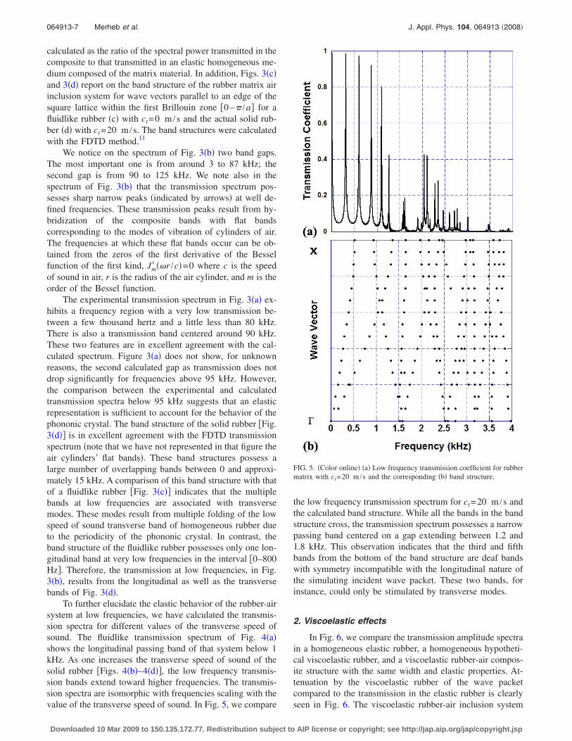
To further elucidate the elastic behavior of the rubber-airsystem at low frequencies, we have calculated the transmis-sion spectra for different values of the transverse speed ofsound. The fluidlike transmission spectrum of Fig. 4�a�shows the longitudinal passing band of that system below 1kHz. As one increases the transverse speed of sound of thesolid rubber �Figs. 4�b�–4�d��, the low frequency transmis-sion bands extend toward higher frequencies. The transmis-sion spectra are isomorphic with frequencies scaling with thevalue of the transverse speed of sound. In Fig. 5, we compare
the low frequency transmission spectrum for ct=20 m /s andthe calculated band structure. While all the bands in the bandstructure cross, the transmission spectrum possesses a narrowpassing band centered on a gap extending between 1.2 and1.8 kHz. This observation indicates that the third and fifthbands from the bottom of the band structure are deaf bandswith symmetry incompatible with the longitudinal nature ofthe simulating incident wave packet. These two bands, forinstance, could only be stimulated by transverse modes.
2. Viscoelastic effects
In Fig. 6, we compare the transmission amplitude spectrain a homogeneous elastic rubber, a homogeneous hypotheti-cal viscoelastic rubber, and a viscoelastic rubber-air compos-ite structure with the same width and elastic properties. At-tenuation by the viscoelastic rubber of the wave packetcompared to the transmission in the elastic rubber is clearlyseen in Fig. 6. The viscoelastic rubber-air inclusion system
FIG. 5. �Color online� �a� Low frequency transmission coefficient for rubbermatrix with ct=20 m /s and the corresponding �b� band structure.
064913-7 Merheb et al. J. Appl. Phys. 104, 064913 �2008�
Downloaded 10 Mar 2009 to 150.135.172.77. Redistribution subject to AIP license or copyright; see http://jap.aip.org/jap/copyright.jsp

presents an attenuated passing band below 1 kHz. Beyondthat frequency, transmission is nearly totally inexistent. Werecall that the transmission in the elastic phononic crystal atlow frequencies extended up to approximately 8 kHz. Thetransmission of the viscoelastic system at low frequencies�inset of Fig. 6� does not exceed 15% of the transmissioncoefficient of the elastic system �Fig. 4�b��.
B. Transmission in air /rubber structure
The calculations discussed in this section were carriedout for the arrays of polymer cylinders located on a honey-comb lattice embedded in air �Fig. 2�b��. The transmissioncoefficient of this structure shown in Fig. 7�a� was computedusing the FDTD method for very long time integration �0.06s�. We notice a large band gap starting at 1.5 and up to morethan 100 kHz. Another gap exists between 0.48 and 1.3 kHz.The transmission level for the band between 1.3 and 1.5 kHzis low �3%�.
The same simulation was carried out for an air/viscoelastic rubber structure based on the generalized eight-element Maxwell model. A comparison between Figs. 7�a�and 7�b� shows a significant drop in the amplitude of the firsttransmitted band ��500 Hz� due to attenuation. In addition,we notice that the narrow passing band for elastic systemcentered on 1.2 kHz disappears or is highly attenuated by theviscoelasticity of the material.
IV. CONCLUSION
In this study, we investigated rubber/air phononic crys-tals with particular attention paid to the fact that in rubber thetransverse speed of sound is significantly lower than the lon-
gitudinal one and that rubbers are materials that may exhibitviscoelastic responses. Consequently, we develop a FDTDmethod for 2D elastic and viscoelastic composite structures.Experimental and calculated transmission spectra for an elas-tic rubber matrix/air inclusions phononic crystal show thatthe system behaves as a fluid/fluid composite due to the largecontrast between the transverse and longitudinal speeds ofsound. We also demonstrate that viscoelasticity can attenuatetransmission over very wide ranges of frequency, leavingonly passing bands at very low frequencies. The two types ofstructures studied here demonstrate the practical design ofelastic or viscoelastic solid rubber/air ABG sound barrierwith dimensions in the range of millimeters to centimeters.
FIG. 6. �Color online� Calculated longitudinal amplitude transmitted �inarbitrary units� through a homogeneous rubber treated as an elastic medium�continuous curve�, a viscoelastic medium �long dash curve�, and the vis-coelastic rubber matrix/air inclusion system �short dash�. The probing wavepacket is the same for the three systems. The inset graph reports the trans-mission coefficient of the viscoelastic rubber-air composite.
FIG. 7. �Color online� Transmission coefficient for an array of touchingpolymer cylinders located on a honeycomb lattice in air �cylinder radius of5.75 mm, hexagon lattice parameter of 19.9 mm� for an �a� elastic rubberand �b� a generalized eight-element Maxwell model of the rubber. The over-all thickness of the phononic crystal is 69 mm.
064913-8 Merheb et al. J. Appl. Phys. 104, 064913 �2008�
Downloaded 10 Mar 2009 to 150.135.172.77. Redistribution subject to AIP license or copyright; see http://jap.aip.org/jap/copyright.jsp
APPENDIX: FDTD RECURSIVE METHOD
In this paragraph we demonstrate how to calculate theintegral Ixxi�t�=�−�
t ��vx�t�� /�x�e−�t−t��/�idt� by a recursivemethod. First we assume that for an incident wave that ar-rives from an elastic medium we have �−�
t ��0t . Then let us
denote w= t− t�⇒dw=−dt�. By replacing t� in the equationwe obtain
Ixxi�t� = �0
t �vx�t − w��x
e−w/�idw . �A1�
Now we calculate Ixxi�t+dt�,
Ixxi�t + dt� = �0
t+dt �vx�t + dt − w��x
e−w/�idw , �A2�
Ixxi�t + dt� = �0
dt �vx�t + dt − w��x
e−w/�idw
+ �dt
t+dt �vx�t + dt − w��x
e−w/�idw . �A3�
By changing s=w−dt⇒ds=dw,
Ixxi�t + dt� = �−dt
0 �vx�t − s��x
e−�s+dt�/�ids
+ �0
t �vx�t − s��x
e−�s+dt�/�ids , �A4�
Ixxi�t + dt� = �vx�t��x
e−dt/�i +�vx�t + dt�
�x
2dt�
+ e−dt/�i�0
t �vx�t − s��x
e−s/�ids . �A5�
Finally we obtain a recursive form for the integral cal-culation:
Ixxi�t + dt� = �vx�t��x
e−dt/�i +�vx�t + dt�
�x
2dt�
+ e−dt/�iIxxi�t� , �A6�
where Ixxi�0�=0.Similar equations are obtained for the yy and xy compo-
nents,
Iyyi�t + dt� = �vy�t��y
e−dt/�i +�vy�t + dt�
�y
2dt�
+ e−dt/�iIyyi�t� , �A7�
Ixyi�t + dt� = �vx�t��y
e−dt/�i +�vx�t + dt�
�y
2dt�
+ e−dt/�iIxyi�t� , �A8�
Iyxi�t + dt� = �vy�t��x
e−dt/�i +�vy�t + dt�
�x
2dt�
+ e−dt/�iIyxi�t� . �A9�
1J. O. Vasseur, P. A. Deymier, A. Khelif, Ph. Lambin, B. Dajfari-Rouhani,A. Akjouj, L. Dobrzynski, N. Fettouhi, and J. Zemmouri, Phys. Rev. E 65,056608 �2002�.
2Ph. Lambin, A. Khelif, J. O. Vasseur, L. Dobrzynski, and B. Djafari-Rouhani, Phys. Rev. E 63, 066605 �2001�.
3J. O. Vasseur, P. A. Deymier, G. Frantziskonis, G. Hong, B. Dajfari-Rouhani, and L. Dobrzynski, J. Phys.: Condens. Matter 10, 6051 �1998�.
4M. Sigalas, M. S. Kushwaha, E. N. Economou, M. Kafesaki, I. E. Psar-obas, and W. Steurer, Z. Kristallogr. 220, 765 �2005�.
5M. Sigalas and E. N. Economou, Solid State Commun. 86, 141 �1993�.6Z. Liu, X. Zhang, Y. Mao, Y. Y. Zhu, Z. Yang, C. T. Chan, and P. Sheng,Science 289, 1734 �2000�.
7I. E. Psarobas, Phys. Rev. B 64, 012303 �2001�.8M. Kafesaki, M. M. Sigalas, and N. Garcia, in Photonic Crystals andLight Localization in the 21st Century, edited by C. M. Soukoulis �Klu-wer, Dordrecht, 2001�, p. 69.
9Polymer Handbook, 3rd ed., edited by J. Brandup and E. H. Immergut�Wiley, New York, 1989�.
10Two-part silicon system, Dow Corning HSII RTV �http://www.ellsworth.com/display/productdetail.html?productid�425&Tab�Vendors�.
11Y. Tanaka, Y. Tomoyasu, and S. Tamura, Phys. Rev. B 62, 7387 �2000�.
064913-9 Merheb et al. J. Appl. Phys. 104, 064913 �2008�
Downloaded 10 Mar 2009 to 150.135.172.77. Redistribution subject to AIP license or copyright; see http://jap.aip.org/jap/copyright.jsp