el diseño
DESCRIPTION
TRANSCRIPT

7 Embodiment Design
Embodiment design is the part of the design process in which, starting fromthe principle solution or concept of a technical product, the design is developedin accordance with technical and economic criteria and in the light of furtherinformation, to the point where subsequent detail design can lead directly toproduction (see Section 4.2).
The draft guideline VDI 2223: Systematic Embodiment of Technical Prod-ucts [7.295] builds on recommendations from the fourth German edition of thisbook along with other sources. In doing so, it presents a generally establishedsystematic procedure for embodiment design.
7.1 Steps of Embodiment Design
Having elaborated the principle solution during the conceptual phase, the under-lying ideas can now be firmed up. During the embodiment phase at the latest,designers must determine the overall layout design (general arrangement andspatial compatibility), the preliminary form designs (component shapes and ma-terials) and the production processes, and provide solutions for any auxiliaryfunctions. During all of this, technological and economic considerations are ofparamount importance. The design is developed with the help of scale drawings,critically reviewed, and subjected to a technical and economic evaluation.
In many cases several embodiment designs are needed before a definitive designappropriate to the desired solution can emerge.
In other words, the definitive layout must be developed to the point wherea clear check of function, durability, production, assembly, operation and costscan be carried out. Only when this has been done is it possible to prepare the finalproduction documents.
Unlike conceptual design, embodiment design involves a large number of cor-rective steps in which analysis and synthesis constantly alternate and complementeach other. This explains why the familiar methods underlying the search forsolutions and evaluation must be complemented with methods facilitating theidentification of errors (design faults) and optimisation. The collection of infor-mation on materials, production processes, repeat parts and standards involvesconsiderable effort.

228 7 Embodiment Design
The embodiment process is complex in that:
• many actions must be performed simultaneously
• several steps must be repeated at a higher level of information
• additions and alterations in one area have repercussions on the existing designin other areas.
Because of this, it is not always possible to draw up a strict plan for the embodimentdesign phase. However, it is possible to suggest a general approach with mainworking steps, see Figure 7.1. Particular problems may demand deviations andsubsidiary steps, which can rarely be predicted precisely. The approach has to beplanned to match the problem at hand, realising that further modifications willhave to be made. Basically, the process will proceed from the qualitative to thequantitative, from the abstract to the concrete, and from rough to detailed designs.It is important to make provision for checks and, if necessary, for corrections.
1. Starting with the principle solution, and using the requirements list, the firststep is to identify those requirements that have a crucial bearing on the em-bodiment design:• size-determining requirements, such as output, throughput, size of connec-
tors, etc.
• arrangement-determining requirements, such as direction of flow, motion,position, etc.
• material-determining requirements, such as resistance to corrosion, servicelife, specified materials, etc.
Requirements suchas thosebasedonsafety, ergonomics, production, assemblyand recycling involve special embodiment considerations, which may affectthe size, arrangement, and selection of materials (see Sections 7.2 to 7.5).
2. Next, the spatial constraints determining or restricting the embodiment de-sign must be identified (for instance clearances, axle positions, installationrequirements, etc.).
3. Once the embodiment-determining requirements and spatial constraints havebeen established, a rough layout, derived from the concept, is produced withthe emphasis on the overall embodiment-determining main function carriers,that is, the assemblies and components fulfilling the main functions. Thefollowing subsidiary questions must be settled, with due regard paid to theprinciples of embodiment design (see Section 7.4):• Which main functions and function carriers determine the size, arrange-
ment and component shapes of the overall layout (for instance, the bladeprofiles in turbomachines or the flow area of valves)?
• Which main functions must be fulfilled by which function carriers jointlyor separately (for instance, transmitting torque and allowing for radialmovement by means of a flexible shaft or by means of a stiff shaft plusa special coupling)? This step is similar to division into realisable modules,as shown in Figure 1.9.

7.1 Steps of Embodiment Design 229
Figure 7.1. Steps of embodiment design

230 7 Embodiment Design
4. Preliminary scale layouts and form designs for the embodiment-determiningmain function carriers must be developed; that is, the general arrange-ment, component shapes and materials must be determined provisionally.To that end, it is advisable to work systematically through the items underthe heading “layout” in the checklist shown in Figure 7.3. The result mustmeet the overall spatial constraints and then be completed so that all of therelevant main functions are fulfilled (for instance by specifying the mini-mum diameters of drive shafts, provisional gear ratios, minimum wall thick-nesses, etc.). Known solutions or existing components (repeat parts, stan-dard parts, etc.) must be shown in simplified form. It may be useful to startworking on selected areas only, combining these into preliminary layoutslater.
5. One or more suitable preliminary layouts must be selected in accordance withthe procedure described in Section 3.3.1 (modified if necessary) by consideringthe relevant items in the checklist shown in Figure 7.3.
6. Preliminary layouts and form designs must now be developed for the remain-ing main function carriers that have not yet been considered because knownsolutions exist for them or they are not embodiment-determining until thisstage.
7. Next, determine which essential auxiliary functions (such as support, reten-tion, sealing and cooling) are needed and, where possible, exploit knownsolutions (such as repeat parts, standard parts, catalogue solutions). If thisproves impossible, search for special solutions, using the procedures alreadydescribed in Section 3.2 and Chapter 6.
8. Detailed layouts and form designs for the main function carriers must nowbe developed in accordance with the embodiment design rules and guide-lines (see Sections 7.3 to 7.5), paying due attention to standards, regulations,detailed calculations and experimental findings, and also to the problemof compatibility with those auxiliary functions that have been realised. Ifnecessary, divide into assemblies or areas that can be elaborated individu-ally.
9. Proceed to develop the detailed layouts and form designs for the auxiliaryfunction carriers, adding standard and bought-out parts. If necessary, refinethe design of the main function carriers and combine all function carriers intooverall layouts.
10. Evaluate the layouts against technical and economic criteria (see Section 3.2.2).If a particular project requires several concepts to be put in more concreteform prior to evaluation, then the embodiment process must not, of course, bepursued beyond what the evaluation of the variants demands. Depending onthe circumstances, it is thus possible, in some cases, to take a decision just assoon as the main function carriers have reached the preliminary layout stage,while in other cases the decision will have to be deferred until after a great dealof detail design. In either event, all of the designs to be compared must be at thesame level of embodiment, since no reliable evaluation is possible otherwise.

7.1 Steps of Embodiment Design 231
11. Fix the preliminary overall layout. The overall layout describes the completeconstruction structure (see Figure 2.13) of the system or product being de-signed.
12. Optimise and complete the form designs for the selected layout by eliminatingthe weak spots that have been identified during the course of the evaluation.If it should prove advantageous, repeat the previous steps and adopt suitablesubsolutions from less favoured variants.
13. Check this layout design for errors (design faults) in function, spatial compat-ibility, etc. (see Figure 7.3), and for the effects of disturbing factors. Make whatimprovements may be needed. The achievement of the objectives with respectto cost (see Chapter 11) and quality (see Chapter 10) must be established atthis point at the latest.
14. Conclude the embodiment design phase by preparing a preliminary parts listas well as a preliminary production and assembly documents.
15. Fix the definitive layout and pass on to the detail design phase.
The representation of the spatial constraints and the embodiment is now generallyobtained by creating a full 3-D digital model. Irrespective of whether a 2-D or 3-Drepresentation is used [7.213]:
• the function and type of the objects must be shown
• the positions of and the necessary space for the objects must be recognis-able through characteristic dimensions, e.g. the overall dimensions, whichcan be used to check the overall spatial compatibility and assembly opera-tions.
When 2-D CAD systems or drawing boards are still used simplifications, such asthose proposed by Lüpertz [7.174], could be used.
In the embodiment phase, unlike the conceptual phase, it is not necessaryto lay down special methods for every individual step, however the followingrecommendations might prove useful.
The search for solutions for auxiliary functions and other subsidiary problemsshould be based either on the procedure described in Chapter 3, but simpli-fied as far as possible, or else directly on catalogues. Requirements, functionsand solutions with appropriate classifying criteria have already been elabo-rated.
The embodiment (layout and form designs) of the function carriers should bebased on the checklist (see Figure 7.3) and involves reference to the principlesof mechanics and structures, and to materials technology. It calls for calculationsranging from the simplest through to complex differential equations and finiteelement analyses. For these calculations, the reader is referred to the literaturelisted in Section 7.5.1, and for even more complex calculations to the domainspecific literature. In some cases it might be necessary to build prototypes or toundertake specific tests.
In the elaboration of embodiment designs, many details have to be clarified,confirmed and optimised. The more closely they are examined, the more ob-

232 7 Embodiment Design
vious it becomes as to whether the right solution concept has been chosen. Itmay appear that this or that requirement cannot be met, or that certain char-acteristics of the chosen concept are unsuitable. If this is discovered during theembodiment phase, it is advisable to re-examine the procedure adopted in theconceptual phase, for no embodiment design, however perfect, can hope to cor-rect a poor concept. This is equally true of the working principles applicable tothe various subfunctions. However, even the most promising concept can causedifficulties in embodiment and detail design. This often happens because vari-ous features were originally treated as subordinate or as not in need of furtherclarification. Attempts to solve these subproblems compel designers to reiteratethe appropriate steps while retaining the selected working structure and overallarrangement.
Experience with the proposed approach for embodiment design has confirmedits basic validity, but has also revealed the following important points [7.211]:
• If prior research has been undertaken or embodiment variants already exist, thestep of producing preliminary embodiments can often be left out.
• Preliminary embodiments can always be left out when only detailed improve-ments are required.
• The solutions for auxiliary functions usually influence the preliminary embod-iment of the main function carriers, so working on these solutions must not beleft until too late in the process.
• A characteristic of successful designers is that they continuously check andmonitor their actions to identify direct and indirect effects.
Many products are not developed from scratch, but are developments or improve-ments of existing ones that take into account new requirements, new knowledgeand experiences. Experience has shown that it is useful to start by analysing thefailures and disturbing factors for an existing solution (see Sections 10.2 and 10.3)and, based on that analysis, to develop a new requirements list (see Figure 7.2).The result of the clarified task will show whether a new working structure—a newprinciple solution—is required, or whether it is sufficient to modify the existingembodiment. It is possible to start at many different places within the overall ap-proach. In some cases a new product can be produced by making improvementsto the details. In other cases, tests of the existing or modified modules may benecessary. The required steps in the overall approach must be selected appropri-ately.
To sum up, embodiment design involves a flexible approach with many iterationsand changes of focus. The individual steps have to be selected and adapted to theparticular situation. The ability to organise one’s own approach while paying dueregard to the fundamental links between the steps and the recommendations weprovide is important (see Section 2.2.1).
In embodiment design, the rules and principles elaborated in Sections 7.2 to 7.5should be followed. Because of the fundamental importance of the identificationof errors (design faults) in several of the steps, the reader is referred to Chapter 10in particular.

7.2 Checklist for Embodiment Design 233
Figure 7.2. Embodiment design phase based on the development of an existing solution. Which of the steps shown inFigure 7.1 needs to be completed follows from an analysis of failures and disturbing factors
7.2 Checklist for Embodiment Design
Embodiment design is characterised by repeated deliberation and verification (seeSection 7.1). Every embodiment design is an attempt to fulfil a given functionwith appropriate layout, component shapes and materials. The process starts withpreliminary scale layouts based on a rough analysis of spatial requirements, andproceeds to consider safety, ergonomics, production, assembly, operation, main-tenance, recycling, costs and schedules.
In dealing with these factors, designers will discover a large number of in-terrelationships, so that their approach must be progressive as well as iterative(verification and correction). Notwithstanding this double character, however, theapproach must always be such as to allow the speedy identification of those prob-lems that must be solved first.
The checklist shown in Figure 7.3 has been derived from the general objectivesand constraints discussed in Section 2.1.7. Although the factors are interrelated,this checklist presents them in a useful procedural order and provides designerswith a systematic check on each one. The checklist thus not only provides a strongmental impetus, but also ensures that nothing essential is forgotten.
All in all, continuous reference to the headings will help designers to developand test their progress in a systematic and time-saving way. Each heading shouldbe examined in turn, regardless of its interrelationship with the rest.

234 7 Embodiment Design
Figure 7.3. Checklist for embodiment design
The actual sequence is no indication of the relative importance of the variousheadings, but ensures a systematic approach. For instance, it would be futile todeal with assembly problems before ascertaining if the required performance orminimum durability is ensured. The checklist thus provides a consistent scrutinyof embodiment design and one that is easily memorised.
7.3 Basic Rules of Embodiment Design
The following basic rules apply to all embodiment designs. If they are ignoredproblems are introduced and breakdowns or accidents may occur. They under-lie nearly all of the steps listed in Section 7.1. When used in conjunction withthe checklist (see Figure 7.3) and with the design fault identification methods(see Chapter 10), they also provide essential assistance with selection and evalua-tion.

7.3 Basic Rules of Embodiment Design 235
The basic rules of clarity, simplicity and safety are derived from the generalobjectives set out in Section 2.1.7, that is:
• fulfilment of the technical function
• economic feasibility
• individual and environmental safety.
The literature contains numerous rules of, and guidelines for, embodiment de-sign [7.168,7.180,7.198,7.205]. On closer analysis it appears that clarity, simplicityand safety are fundamental to all of them and are important prerequisites fora successful solution.
Clarity—that is, clarity of function or lack of ambiguity of a design—facilitatesreliable prediction of the performance of the final product and in many cases savestime and costly analyses.
Simplicity generally guarantees economic feasibility. A smaller number of com-ponents and simple shapes are produced more quickly and easily.
Safety imposes a consistent approach to the problems of strength, reliability,accident prevention and protection of the environment.
In short, by observing these three basic rules, designers can increase theirchances of success because they focus attention on, and help to combine, functionalefficiency, economy and safety. Without this combination no satisfactory solutionis likely to emerge.
7.3.1 Clarity
In what follows we shall be applying the basic rule of clarity to the various headingsof the checklist in Figure 7.3.
Function
Within a given function structure, an unambiguous interrelationship between thevarious subfunctions and the appropriate inputs and outputs must be guaranteed.
Working Principle
The chosen working principle, in terms of the physical effects, must reveal a clearrelationship between cause and effect, thus ensuring an appropriate and econom-ical layout.
The chosen working structure, comprising several individual working princi-ples, must guarantee an orderly flow of energy, material and signals. If it does not,undesirable and unpredictable effects such as excessive forces, deformations andwear may ensue.
By paying attention to the deformations associated with a given loading, and alsoto thermal expansion, designers must make the necessary allowances for possibleexpansion in a given direction.
The widely used bearing pairs, with a locating and a nonlocating bearing (seeFigure 7.4a) have a clearly defined behaviour. The stepped bearing pair (see Fig-ure 7.4b), on the other hand, should be specified only when the expected changes

236 7 Embodiment Design
Figure 7.4. Basic bearing arrangements: a Locating and nonlocating arrangement: left-hand locating bearing takes upall the axial forces, right-hand sliding bearings permit unimpeded axial movement due to thermal expansion; accuratecalculations are possible. b Stepped bearing arrangement: the axial loading of the bearings depends on the preload andthermal expansion and cannot be clearly determined; a modification is the “floating arrangement” in which the bearingsare provided with axial clearance; in that case, thermal expansion is possible to a limited extent but there is no precise shaftlocation. c Spring-loaded bearing arrangement: here the disadvantages of the stepped bearing arrangement are largelyeliminated, though the constantly applied axial load may reduce the bearing life; forces resulting from thermal expansioncan be determined by spring force deflection diagrams; the shaft is located precisely provided the axial force Fa acts onlytowards the right or does not exceed the preloading Fp
in length are negligible or when the resulting play in the bearings is permissible. Bycontrast, a spring-loaded arrangement, in which the operating axial force Fa doesnot exceed the pre-load Fp, will permit a clear definition of the force transmissionpath (see Figure 7.4c).
Combined bearing arrangements often present problems. The combinationshown in Figure 7.5a consists of a needle roller bearing which is intended totransmit the radial forces and a ball bearing which is meant to transmit the axialforces. However, this particular arrangement does not clearly define the transmis-sion path for the radial forces, because the inner and outer races of both bearings

7.3 Basic Rules of Embodiment Design 237
Figure 7.5. Combined rolling-element bearing. a Transmission path of radial forces not clear; b combined rolling bearingwith the same elements as in a, but clear identification of the transmission paths of the radial and axial forces
are restrained radially. As a result, the service life cannot be predicted accurately.The arrangement shown in Figure 7.5b, on the other hand, satisfies the clarity rulewith similar elements, provided the designer ensures during assembly that theright-hand race has enough radial play, thus making certain that the ball bearingtransmits axial forces only.
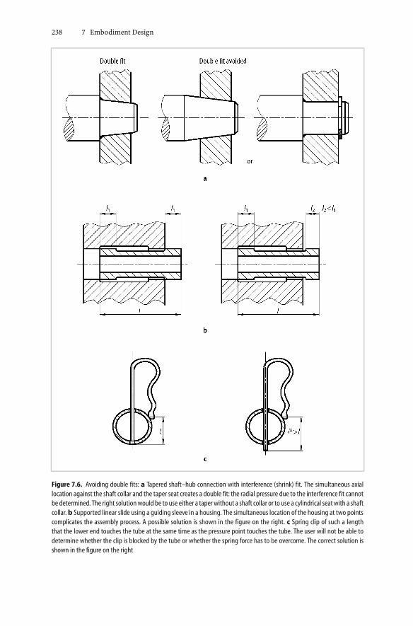
Doublefits conflictwith thebasic ruleof clarity.Theseoccurwhenacomponent issupported or guided by two surfaces at the same time, and these surfaces are eitheron different planes or on different cylindrical sections. In such cases, the surfaceshave to be machined separately and will therefore have different dimensions causedby the tolerances. As a consequence, the force flow cannot be predicted clearly andassembly is made more difficult. Even though modern production machines havereduced the problems with tolerances, the lack of clarity will still affect functionfulfilment and ease of assembly unless double fits are avoided. Double fits appearin various forms. Figure 7.6 shows examples and corrective measures.
Layout
The layout (general arrangement) and form design (shapes and materials) requirea clear definition of the magnitude, type, frequency and duration of loads. Ifthese data are not available, the implementation must be based on reasonableassumptions and the expected service life specified accordingly.
In any case, the embodiment must be such that the loads can be defined andcalculated under all operating conditions. No impairment of the function or thedurability of a component must be allowed to arise.
Similarly, following thechecklist inFigure7.3,behaviourwith respect to stability,resonance, wear and corrosion must be clearly established.
Very often one comes across double arrangements, i.e. doubling up workingprinciples for safety’s sake, which conflict with the rule of clarity. Thus a shaft–hub connection designed as a interference fit will not have a better load-carryingcapacity if it is also provided with a key, as in Figure 7.7. The extra elementmerely ensures correct positioning in the circumferential sense, but because of thereduction in the area at A, the resulting stress concentration at B and the presence
238 7 Embodiment Design
Figure 7.6. Avoiding double fits: a Tapered shaft–hub connection with interference (shrink) fit. The simultaneous axiallocation against the shaft collar and the taper seat creates a double fit: the radial pressure due to the interference fit cannotbe determined. The right solutionwould be to use either a taperwithout a shaft collar or to use a cylindrical seatwith a shaftcollar. b Supported linear slide using a guiding sleeve in a housing. The simultaneous location of the housing at two pointscomplicates the assembly process. A possible solution is shown in the figure on the right. c Spring clip of such a lengththat the lower end touches the tube at the same time as the pressure point touches the tube. The user will not be able todetermine whether the clip is blocked by the tube or whether the spring force has to be overcome. The correct solution isshown in the figure on the right

7.3 Basic Rules of Embodiment Design 239
of complicated and almost incalculable stresses at C, it decreases the strength ina drastic and fairly unpredictable manner.
Schmid [7.242] has shown that an axially preloaded taper joint for the transmis-sion of torque requires a spiralling motion when the hub is assembled on the shaftin order to ensure a reliable interference fit, and the use of a key prevents this.
The employment of an interference fit to achieve the maximum torque capacityis only possible by leaving out the key. The solution shown in Figure 7.7 is onlyacceptable when the correct positioning of the hub relative to the shaft is the cruxof the task, in which case a sliding fit is more appropriate.
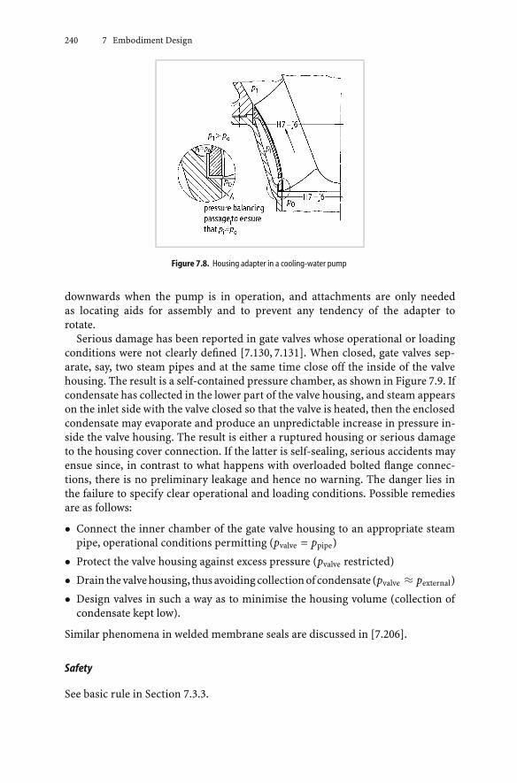
Figure 7.8 shows a housing adapter for a centrifugal pump which can be used toprovide various annulus profiles to fit different blade shapes so that new housingsneed not be constructed for each case. Unless the intermediate pressure in thegap between the adapter and the housing can be clearly regulated, or some othermeans of attachment is used, the adapter might travel upwards and damage theblades by rubbing against them.
This is particularly true when similar fits (H7-j6) are chosen for the two lo-cating diameters which are approximately the same size. This is because, de-pending on production tolerances and working temperatures, gaps may appear,the relative sizes of which are unpredictable and which produce unknown in-termediate pressures in the space between the adapter and the housing. The so-lution shown in Figure 7.8 (detail) ensures, by means of the specially designedconnecting passage A (which must have a flow area roughly four to five timesgreater than the maximum gap area that might appear at the upper locating di-ameter), a clearly definable intermediate pressure, corresponding to the lowerinlet pressure of the pump. As a result, the housing adapter is always pressed
Figure 7.7. Combined shaft–hub connection achieved by means of shrink fit and key: an example of not applying theprinciple of clarity
240 7 Embodiment Design
Figure 7.8. Housing adapter in a cooling-water pump
downwards when the pump is in operation, and attachments are only neededas locating aids for assembly and to prevent any tendency of the adapter torotate.
Serious damage has been reported in gate valves whose operational or loadingconditions were not clearly defined [7.130, 7.131]. When closed, gate valves sep-arate, say, two steam pipes and at the same time close off the inside of the valvehousing. The result is a self-contained pressure chamber, as shown in Figure 7.9. Ifcondensate has collected in the lower part of the valve housing, and steam appearson the inlet side with the valve closed so that the valve is heated, then the enclosedcondensate may evaporate and produce an unpredictable increase in pressure in-side the valve housing. The result is either a ruptured housing or serious damageto the housing cover connection. If the latter is self-sealing, serious accidents mayensue since, in contrast to what happens with overloaded bolted flange connec-tions, there is no preliminary leakage and hence no warning. The danger lies inthe failure to specify clear operational and loading conditions. Possible remediesare as follows:
• Connect the inner chamber of the gate valve housing to an appropriate steampipe, operational conditions permitting (pvalve = ppipe)
• Protect the valve housing against excess pressure (pvalve restricted)
• Drain thevalvehousing, thusavoidingcollectionof condensate (pvalve ≈ pexternal)
• Design valves in such a way as to minimise the housing volume (collection ofcondensate kept low).
Similar phenomena in welded membrane seals are discussed in [7.206].
Safety
See basic rule in Section 7.3.3.

7.3 Basic Rules of Embodiment Design 241
Figure 7.9. Gate valve with relatively large lower collecting area
Ergonomics
Inhuman–machine relationships, correct operationmustbeensuredvia the logicallayout of equipment and controls.
Production and Quality Control
These must be facilitated by clear and comprehensive data in the form of productmodels as well as drawings, parts lists and instructions; and adherence to theprescribed production and quality control procedures.

242 7 Embodiment Design
Assembly and Transport
Much the same is true of assembly and transport. A clear assembly sequencepreventing mistakes should be incorporated into the design (see Section 7.5.8).
Operation and Maintenance
Clear installation instructions and the appropriate embodiment design must en-sure that:
• the performance is easily checked
• inspection and maintenance involves the smallest possible variety of tools andequipment
• the scope and schedules of inspection and maintenance are defined
• inspection and maintenance can be checked after they have been carried out(see Section 7.5.10).
Recycling
Designers should provide (see Section 7.5.11):
• clear separation of materials that are incompatible with regard to recycling
• clear sequences of assembly and disassembly.
7.3.2 Simplicity
For technical applications, the word “simple” means “not complex”, “easily under-stood” and “easily done”.
A solution seems simpler if it can be effected with fewer components, because,for example, the probability of lower production costs, less wear and lower main-tenance is then greater. However, this is only true if the arrangement and shapesof the components are kept simple. Hence designers should always aim at theminimum number of components with the simplest shapes [7.168, 7.198, 7.206].
As a rule, however, a compromise has to be made. The fulfilment of a functionalways demands a certain minimum number of components. Cost efficiency oftennecessitates a decision between numerous components with simple shapes butwith greater overall production effort, and, for example, a single cheaper castcomponent with the greater uncertainty it may entail in delivery. Simplicity mustalways be assessed from a holistic perspective—what constitutes “simpler” inindividual cases depends on the problem and the constraints.
In what follows we shall be applying the basic rule of simplicity to the variousheadings of the checklist shown in Figure 7.3.
Function
In principle, only a minimum number and a clear and consistent combination ofsubfunctions should be pursued when considering the function structure.
7.3 Basic Rules of Embodiment Design 243
Working Principle
In selecting working principles, only those involving a small number of processesand components, that have obvious validity and involve low costs should be takeninto consideration.
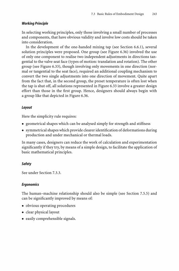
In the development of the one-handed mixing tap (see Section 6.6.1), severalsolution principles were proposed. One group (see Figure 6.36) involved the useof only one component to realise two independent adjustments in directions tan-gential to the valve seat face (types of motion: translation and rotation). The othergroup (see Figure 6.33), though involving only movements in one direction (nor-mal or tangential to the seat face), required an additional coupling mechanism toconvert the two single adjustments into one direction of movement. Quite apartfrom the fact that, in the second group, the preset temperature is often lost whenthe tap is shut off, all solutions represented in Figure 6.33 involve a greater designeffort than those in the first group. Hence, designers should always begin witha group like that depicted in Figure 6.36.
Layout
Here the simplicity rule requires:
• geometrical shapes which can be analysed simply for strength and stiffness
• symmetrical shapes which provide clearer identification of deformations duringproduction and under mechanical or thermal loads.
In many cases, designers can reduce the work of calculation and experimentationsignificantly if they try, by means of a simple design, to facilitate the application ofbasic mathematical principles.
Safety
See under Section 7.3.3.
Ergonomics
The human–machine relationship should also be simple (see Section 7.5.5) andcan be significantly improved by means of:
• obvious operating procedures
• clear physical layout
• easily comprehensible signals.

244 7 Embodiment Design
Production and Quality Control
Production and quality control can be simplified, and at the same time made fasterand more accurate, if:
• geometrical shapes permit the use of well-established, time-saving methods
• production operations are minimised and have short setting-up and waitingtimes
• shapes are chosen to facilitate the inspection process.
Leyer, when discussing changes in production methods [7.166], uses the exam-ple of a sliding control valve approximately 100 mm long to demonstrate howthe replacement of a complicated casting by a brazed product made of geo-metrically simple turned parts helped to overcome difficulties and paved theway for more economical production. Even though modern casting techniquesnow allow more intricate shapes to be produced relatively easily, further sim-plifications might still be expedient (see Figure 7.10). Step 3 helps to simplifythe geometrical shape of the central, tubular part. Step 4 (fewer parts) can betaken when the surface areas at right angles to the valve axis need not be re-tained.
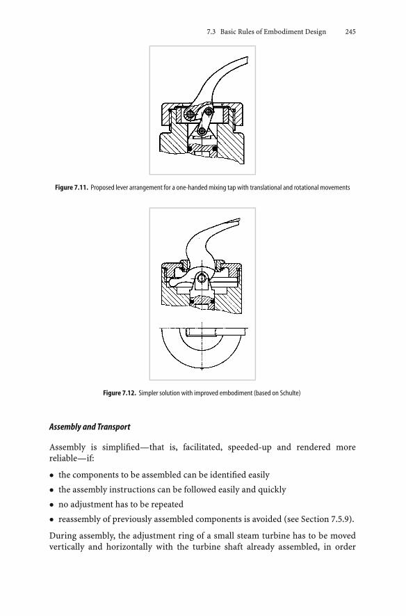
A further example is provided by the one-handed mixing tap discussed earlier.The design of the lever arrangement shown in Figure 7.11 is expensive to make,difficult to clean (slits, open recesses) andnot aesthetically pleasing.Theone shownin Figure 7.12 is much simpler and also more suitable for longer production runs.The lever, whose end can slide and rotate in a circumferential groove, requiresa smaller number of parts and avoids wear in areas that are difficult to readjust.All in all, therefore, this solution is by far the better because it is more economic,easier to clean and looks nicer.
Figure 7.10. Simplification of a sliding control valve: 1 Casting is difficult and expensive; 2 Improvement by splitting intosimple, brazed parts; 3 Simplification of central tubular part; 4 Further simplification possibility (1 and 2 after [7.166])
7.3 Basic Rules of Embodiment Design 245
Figure 7.11. Proposed lever arrangement for a one-handed mixing tap with translational and rotational movements
Figure 7.12. Simpler solution with improved embodiment (based on Schulte)
Assembly and Transport
Assembly is simplified—that is, facilitated, speeded-up and rendered morereliable—if:
• the components to be assembled can be identified easily
• the assembly instructions can be followed easily and quickly
• no adjustment has to be repeated
• reassembly of previously assembled components is avoided (see Section 7.5.9).
During assembly, the adjustment ring of a small steam turbine has to be movedvertically and horizontally with the turbine shaft already assembled, in order

246 7 Embodiment Design
Figure 7.13. Adjustable sealing ring of an industrial steam turbine; adjustments at A in the same sense produce verticalmovement, adjustments atA in the opposite sense produce a rotation aboutB that approximates to a horizontalmovement
to ensure uniform clearance around the labyrinth seal. Doing this without hav-ing to remove the shaft several times for adjustment poses a problem that canbe solved by the design shown in Figure 7.13. The adjustment can be madeat the joint by rotating the adjustment screws A in the same sense, produc-ing vertical movement only, and by rotation in the opposite sense, producinga tilting movement about pivot B that approximates to horizontal movement.The pivot itself must, however, allow for vertical movement during the adjust-ment and also for radial heat expansion when the turbine is operating. This isachieved with a few easily produced elements with simple shapes. A suitablearrangement of the surfaces, moreover, obviates the need to secure the pivotpin with additional locking elements: it is located in such a way that it can notfall out.
Operation and Maintenance
With respect to operation and maintenance, the simplicity rule means:
• operation must be possible without special or complicated instructions
• the sequence of operations must be clear and simple, and any deviations or faultseasily identified
• maintenance must not be awkward, laborious and time-consuming.

7.3 Basic Rules of Embodiment Design 247
Recycling
Simplicity for recycling can be realised by:
• use of recyclable materials
• simple assembly and disassembly processes
• simplicity of the parts themselves (see Section 7.5.11).
7.3.3 Safety
1. Nature and Scope of Safety Measures
Safety considerations affect both the reliable fulfilment of technical functionsand also the protection of humans and the environment. Designers have re-course to a safety methodology that, following the German industry standardDIN 31 000 [7.57], includes the following three levels:
• direct safety
• indirect safety
• warnings.
In general, designers should try to guarantee safety by using direct safety, thatis, by choosing a solution that precludes danger from the outset. Only when thisproves impossible should they have recourse to indirect safety, in other words,constructing special protective systems [7.58 to 7.60]. Warnings, which merelypoint out dangers and indicate danger areas, can be used to support direct andindirect safetymeasuresby, for example, pointingout special features, obstructionsand disturbances. Only as a last resort should warnings be used on their own, andnever as an easily implemented safety measure.
In the solution of technical problems, designers are faced with several con-straints, not all of which they can hope to overcome simultaneously. They mustnevertheless strive to provide a solution that comes nearest to satisfying all the re-quirements. The strength of an unavoidable safety requirement may, under certaincircumstances, put the realisation of the whole project in doubt. A high demandfor safety can greatly complicate a design and, by reducing clarity, may even lowerthe inherent safety of the product. Moreover, safety provisions may also rendera product uneconomic and lead to its abandonment.
Such cases, however, are exceptional, because safety and economy generallygo hand-in-hand in the long term. This is particularly true of expensive andcomplex plant and machinery. Only smooth, accident-free and safe operationcan ensure long-term economic success. Protection against accidents or damage,moreover, goes hand-in-hand with reliability [7.75, 7.312]. Reliability makes itpossible to operate a machine to full capacity, even though poor reliability maynot necessarily lead to accidents or damage. All in all, it is therefore advisable toachieve safety by treating direct and indirect safety measures as an integral partof system design.

248 7 Embodiment Design
There are many different ways of applying safety measures in mechanical en-gineering. Therefore, we consider it necessary to provide some definitions be-fore discussing the measures in detail. The withdrawn German industry standardDIN 31 004 (1979) defined safety as “being free from danger”, a “danger” beinga threat for which the type, size and action is known. A dangerous situation is onethat can cause damage to persons or things. This DIN standard was replaced inNovember 1982 by DIN 31 004 Part 1 [7.61]. The basic terms are defined as follows:
Safety is a state in which the risk is smaller than the risk limit.Risk limit is the largest but still acceptable system-specific risk relating
to a particular technical process or situation.Risk is described by the frequency (probability) and the expected
extent of the damage (scope).
Whereas the initial DIN standard defined protection as the limitation of danger inorder to prevent damage, the 1982 standard uses the following definition:
Protection is the reduction of risk by suitable means in order to reducethe frequency of occurrence and/or the extent of damage.
The DIN EN 292 standard [7.57] now uses these terms in a more general way.This development of the standard demonstrates that there is no absolute safetyin the sense of complete freedom from danger. In common with many aspects oflife, the use of technical systems always involves a certain risk. Safety measuresaim to reduce risks to an acceptable level. However, what is acceptable (the risklimit) can only be quantified in a few cases. Now and in the future this limit will bedetermined by technical knowledge and social standards, and in no small measureby the experience and responsibilities of design engineers.
In the context of safety, it is very important to ensure reliability:
Reliability is the ability of a technical system to satisfy its operationalrequirements within the specified limits and for the requiredlife (definition based on [7.75, 7.76]).
It is clear that the reliability of individual components of a machine or the machineitself, as well as the reliability of any protective systems and devices, are importantrequirements for safety. Without state-of-the-art quality that ensures reliability,protective measures are of doubtful value.
One measure of reliability is the operational availability of a technical system.
Availability is the percentage of time the system is available for opera-tion compared to the maximum possible time or compared toa particular target time.
Safety concerns the following areas (see Figure 7.14):
Operational safety is the limitation of danger (reducing risk) during the op-eration of technical systems in order to prevent damage tothe systems themselves and their immediate environment,such as the workplace, neighbouring systems, etc.

7.3 Basic Rules of Embodiment Design 249
Figure 7.14. Relationship between component and functional reliability on the one hand and operational, operator andenvironmental safety on the other
Operator safety is the limitation of danger to persons using technical sys-tems either at their workplace or outside, for example forsport or leisure.
Environmental safety is the limitation of damage to the environment in whichtechnical systems are used.
Protective measure is the use of protective systems or devices to limit existingdangers and reduce risks to acceptable levels where thesecannot be achieved through direct safety measures.
The reliability of assemblies and of their interaction—that is, the functional reli-ability of a machine or a protective system—is crucial for operational, operatorand environmental safety [7.179]. For designers, all these areas of safety are closelyconnected when developing a concept and its embodiment. A safety methodologyshould therefore give equal weight to each of the areas [7.210].
2. Direct Safety
Direct safety measures achieve safety through systems or components activelyinvolved in the performance of a particular task. To ensure and evaluate the safefunctioning and durability of components, designers can adopt one of severalsafety principles [7.210]. There are three basic principles, namely:
• safe-life principle
• fail-safe principle
• redundancy principle.
The safe-life principle demands that all components and their connections beconstructed in such a way as to allow them to operate without breakdown ormalfunction throughout their anticipated lives. This is ensured by:

250 7 Embodiment Design
• clear specification of the operating conditions and environmental factors, suchas the anticipated loads, service life, operating conditions, etc.
• adequately safe embodiment based on proven principles and calculations
• numerous and thorough inspections during production and assembly
• analysis of components or systems to determine their durability when they areoverloaded (load levels and/or running time) or subjected to adverse environ-mental influences
• determination of the limits of safe operation, with due regard being paid topossible breakdowns.
It is characteristic of this principle that it bases safety exclusively on accuratequalitative and quantitative knowledge of all of the influences at work or on the de-termination of the limits of failure-free operation. The application of this principlecalls for a great deal of experience, or for costly and time-consuming preliminaryinvestigations, and for continuous monitoring of the state of components. If a fail-ure should nevertheless occur, and if a safe-life is essential, then as a rule there willbe a serious accident, for instance the fracture of an aeroplane wing or the collapseof a bridge.
The fail-safe principle allows for the failure of a system function or for a compo-nent fracture during the service life by ensuring that grave consequences do notensue. To that end:
• a function or capacity, however small, must be preserved to prevent dangerousconditions
• a restricted function must be fulfilled by the failing component or by someother component until such time as the plant or machine can be removed fromoperation without danger
• the failure or breakdown must be identifiable
• the effect of the failing component on the overall safety of the system must beassessable.
In essence, the impairment of a main function must be signalled. The signal cantake various forms (increasing vibrations, loss of sealing, loss of power, slowingdown), each without causing immediate danger. In addition, special monitoringsystems may be provided to indicate the incipient failure to the operator. Theirlayout should be governed by the general principles of protective systems. Thefail-safe principle presupposes knowledge of the progress of a failure and providesa means for taking over or maintaining the impaired function.
By way of example, let us consider a spherical rubber element in an elasticcoupling (see Figure 7.15). The first visible crack appears on the outer layer, butthe function is not yet impaired (State 1). Only when the number of revolutionsunder load is increased does the stiffness begin to decrease with a consequentchange in the behaviour of the coupling, which manifests itself, for instance, bya lowering of the critical speed (State 2). With further operation, the crack growslarger and causes the stiffness to decrease still further (State 3), but even if the

7.3 Basic Rules of Embodiment Design 251
Figure 7.15. Fail-safe behaviour of an elastic coupling: crack-state and stiffness against number of revolutions
crack went right through, there would not be a complete failure of the coupling.Therefore, no sudden effect with serious consequences need be feared.
Another example is the behaviour of flange bolts made of a tough materialwhich, on overloading, exceed their yield strength and deform plastically, resultingin a reduction of preload and, hence, a reduction of the clamping force. Theirimpaired function is indicated by the resulting loss in flange sealing but does notgive rise to sudden failure.
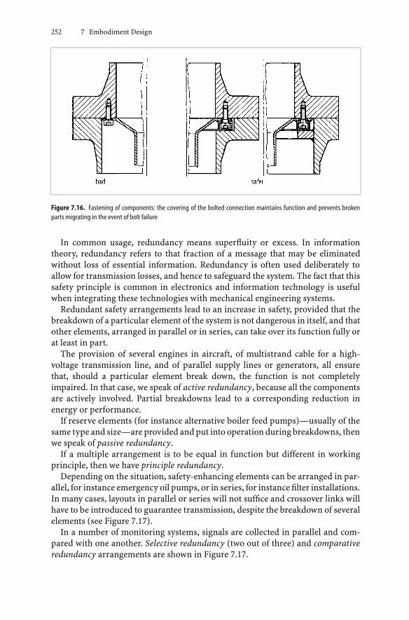
Figure 7.16 illustrates two safe methods of fastening components. The meansof attachment should be designed such that, even if the bolts begin to fail, themountings remain in place, no broken parts can migrate, and the equipmentcontinues to function to some extent [7.206].
The redundancy principle provides another means of increasing both the safetyand the reliability of systems.
252 7 Embodiment Design
Figure 7.16. Fastening of components: the covering of the bolted connection maintains function and prevents brokenparts migrating in the event of bolt failure
In common usage, redundancy means superfluity or excess. In informationtheory, redundancy refers to that fraction of a message that may be eliminatedwithout loss of essential information. Redundancy is often used deliberately toallow for transmission losses, and hence to safeguard the system. The fact that thissafety principle is common in electronics and information technology is usefulwhen integrating these technologies with mechanical engineering systems.
Redundant safety arrangements lead to an increase in safety, provided that thebreakdown of a particular element of the system is not dangerous in itself, and thatother elements, arranged in parallel or in series, can take over its function fully orat least in part.
The provision of several engines in aircraft, of multistrand cable for a high-voltage transmission line, and of parallel supply lines or generators, all ensurethat, should a particular element break down, the function is not completelyimpaired. In that case, we speak of active redundancy, because all the componentsare actively involved. Partial breakdowns lead to a corresponding reduction inenergy or performance.
If reserve elements (for instance alternative boiler feed pumps)—usually of thesame type and size—are provided and put into operation during breakdowns, thenwe speak of passive redundancy.
If a multiple arrangement is to be equal in function but different in workingprinciple, then we have principle redundancy.
Depending on the situation, safety-enhancing elements can be arranged in par-allel, for instance emergency oil pumps, or in series, for instance filter installations.In many cases, layouts in parallel or series will not suffice and crossover links willhave to be introduced to guarantee transmission, despite the breakdown of severalelements (see Figure 7.17).
In a number of monitoring systems, signals are collected in parallel and com-pared with one another. Selective redundancy (two out of three) and comparativeredundancy arrangements are shown in Figure 7.17.

7.3 Basic Rules of Embodiment Design 253
Figure 7.17. Redundant arrangements
Redundancy layouts cannot, however, replace the safe-life or fail-safe principles.Two cable cars operating in parallel will, admittedly, increase the reliability ofpassenger transport, but this will contribute nothing to the safety of the individualcars. The redundant layout of aircraft engines will not increase safety if any of theengines might explode and hence to endanger the system. In short, an increase insafety can only be guaranteed if the redundant element satisfies the safe-life or thefail-safe principle.
Adherence to all the principles we have mentioned—that is, the attainment ofsafety in general—is greatly facilitated by the principle of the division of tasks (seeSection 7.4.2) and by the two basic rules of clarity and simplicity, as we shall nowtry to show with the help of an example.
The principle of the division of tasks and the clarity rule have been applied withgreat consistency to the construction of a helicopter rotor head (see Figure 7.18),and helped the designers to come up with a particularly safe construction basedon the safe-life principle. Each of the four rotor blades exerts a radial force on therotor head due to the centrifugal inertia force, and a bending moment due to theaerodynamic loading. The rotor blades must also be able to swivel so that theirangles of incidence can be changed. A high safety level is achieved by the followingmeasures:
• A completely symmetrical layout so that the external bending moments and theradial forces at the rotor head cancel out.
• The radial forces are transmitted exclusively by the torsionally flexible memberZto the main central component where they cancel each other out.
• The bending moment is only transmitted through part B and is taken up by theroller bearings in the rotor head.
As a result, every component can be optimally designed in accordance with itstask. Complicated joints and shapes are avoided and the necessary high level ofsafety is attained.

254 7 Embodiment Design
Figure 7.18. Rotor blade attachment of a helicopter based on the principle of the division of tasks (Messerschmitt–Bölkarsystem)
3. Indirect Safety
Indirect safety measures involve the use of special protective systems and protec-tive devices. They are applied whenever direct safety measures prove inadequate.A detailed discussion of indirect safety measures for technical systems can befound in [7.215]. In what follows, the most important elements of these measuresare described.
Protective systems react when danger occurs. To that end, their function structureincludes a signal transformation with an input that capturesthe danger and an output that removes it.
The working structure of a protective system is based on a function structure withthe following main functions: capture–process–act. Examples are the multipleredundant monitoring of temperatures in a nuclear reactor; the monitoring ofrobots in inaccessible workplaces; the sealing of areas when they are subject toX-rays; and the automatic checking of the locking of centrifuge covers prior tooperation. The required actions can involve removing, limiting or separating.
Protective devices fulfil protective functions without transforming signals.
Examples are a pressure safety valve (see Figure 7.22); a shaft coupling that slipswith torque overload; a pin that shears to limit excessive forces; and safety belts incars. Their main action is removing or limiting. They can form part of a protectivesystem.
Protective barriers fulfil protective functions without acting.
These barriers are passive, and not able to act on their own. They do not transformsignals and therefore do not require a function structure that involves this trans-formation. They protect by separating; that is, by keeping persons and equipment

7.3 Basic Rules of Embodiment Design 255
at a distance from danger using physical barriers, covers, fences, etc. They aredescribed in DIN 31 001, Parts 1 and 2 [7.58, 7.59]. Locking devices, according toPart 5 of this standard [7.60], are regarded as protective systems.
Basic Requirements
Indirect safety measures have to fulfil the following basic requirements:
• operate reliably
• function when danger occurs
• resist tampering.
Operate Reliably
Reliable operation means that: the working principle and the embodiment allowunambiguous operation; the layout follows the established rules; production andassembly are quality-controlled; and the protective systems and devices are rig-orously tested. The safety modules and their functional links should be based ondirect safety principles and demonstrate safe-life or fail-safe behaviour.
Function When Danger Occurs
This requirement means that:
• the protective function has to be available from the start of the dangeroussituation and must last throughout the period of danger
• the protective function should not cease or the protective device should not beremoved before the dangerous situation has completely ended.
Figure 7.19 shows example layouts for safety fence contacts for a machine guard.Closed contacts signal that the safety fence is in position. Layout a has severedeficiencies because the contact movement relies upon the spring force alone andis not bi-stable (see Section 7.4.4). If the spring breaks or the contacts stick together,the contact will not be broken, that is, the machine can be started with the safety
Figure7.19. Layouts for safety fence contacts for amachineguard.aProtectionnotguaranteedbecause contactmovementrelies on a spring force alone. b Protection guaranteed because activation relies on form fit. c Bi-stable behaviour added toform fit activation in b

256 7 Embodiment Design
fence open. Layout b will always function when danger occurs. Sticking contactswill be opened because the effect relies on form rather than spring force, and ifparts break they will not fall onto the contacts. Layout c also makes use of form foractivation, but adds spring force and bi-stable behaviour. Further examples can befound in [7.215].
Resist Tampering
Resistance to tampering means that the protection cannot be reduced or removedby unintended or intended actions. If we consider the safety fence contact inFigure 7.19, it should be designed such that actions that prevent correct operationare not possible. The best way to achieve this is to use a cover that cannot be openedwithout tools or without stopping the machine.
The requirements of protective systems and devices are listed in the followingparagraphs followed by those of protective barriers.
Protective Systems and Devices
Protective systems and devices render endangered plant or machinery safe au-tomatically, with the aim of preventing danger to persons and machinery. Inprinciple, the following approaches are available:
• When danger occurs, prevent the consequences by disabling the plant or ma-chinery or preventing any plant or machinery in a dangerous state from beingput into operation.
• When there is a continuous danger, avoid its effects by introducing protectivemeasures.
The basic requirements “operate reliably”, “function when danger occurs”, and“resist tampering” are supported by fulfilling the following requirements.
Warning
When a protective system notes changes in the working conditions, a warning mustbe provided that indicates the change and the cause of the warning. Examples are“oil level too low”, “temperature too high”, and “safety fence open”. Recommendedacoustic and optical signals are given in DIN 33 404 [7.69], colours for warninglights and push buttons in DIN IEC 73/VDE 0199 [7.77], and special safety symbolsin DIN 4844 [7.40–7.42].
Two-Step Action
If the dangerous situation emerges so slowly that operator action can reduce thedanger, then a warning should be given before a protective action is initiated.
Between the two steps, there should be a sufficiently large and clearly definedchange in the danger variable. For example, if pressure is the danger variable beingmonitored, a warning could be given at 1.05 pnormal and shutdown initiated at 1.1pnormal.

7.3 Basic Rules of Embodiment Design 257
If the dangerous situation emerges too quickly, the protective system shouldreact immediately and signal its response clearly. The terms “slowly” and “quickly”must be interpreted in the context of the cycle time of the technical process andthe reaction time required [7.243].
Self-Monitoring
A protective system must be self-monitoring; that is, it must be triggered notonly when the system breaks down, but also by faults in its own system. Thisrequirement is best satisfied by the stored energy principle, because, when thisis applied, the energy needed to activate the safety device is stored within thesystem and any disturbance of or fault in the protective system will release thatenergy and switch off the plant or machinery. This principle can be used not onlyin electronic protective systems but also in mechanical, hydraulic and pneumaticsystems.
The stored energy principle has been used in the valve shown in Figure 7.20.When the valve opens, the spring is compressed by the operating oil pressure.When the oil pressure reduces, the spring extends and the valve closes. Failureof the spring will not inhibit the closure of the valve because of the particularconfiguration used. The flow direction selected and the suspended configurationsupport the requirement of always functioning when danger arises.
A further example of the use of the stored energy principle in a hydraulic systemis shown inFigure7.21. In thisprotective system,pump1withapressure-regulatingvalve 2 ensures a constant pre-pressure pp. The protective system with the pressureps is connected to the pre-pressure system by means of an orifice 3. Under normalconditions, all outlets are closed, so that the quick-action stop valve 4 is held open
Figure 7.20. Layout of a quick-action valve. In the event of a drop in oil pressure p, the spring force, the flow pressure onthe valve face and the weight of the valve act together to guarantee the rapid closure of the valve

258 7 Embodiment Design
Figure 7.21. Hydraulic protection system employed to prevent incorrect axial shaft positions based on the stored energyprinciple
by the pressure ps, allowing energy to be supplied to the machine. In the case ofa faulty axial shaft position, the piston valve 5 at the end of the shaft opens, thepressure ps drops, and further energy supplies are cut off by the quick-action stopvalve 4. The same effect is produced by damage to the pre-pressure or protectivesystem, for example by pipe fracture, lack of oil or pump failure. The system isself-monitoring.
A systemoperatingon theactive energyprinciple, where energy is only generatedin the case of danger, cannot detect a failure in its own system. Therefore, thisapproach should only be used to provide the warning signals of a protective systemwhen a monitoring system is also available and the system is checked regularly.The possibility that a protective system based on the stored energy principle cancause interruptions that are not caused by a dangerous situation but instead by theprotective system itself should be met by increasing the reliability of the systemelements, and not through application, for example, of the active energy principle.
Redundancy
The failure of a protective system or device should be seen as a real possibility.Because a single protective system may break down, its mere doubling or repli-cation ensures greater safety: it is unlikely that all the systems will fail at once.A solution that is often applied in protective systems is redundancy based on twofrom three selection. Three sensors are used to detect the same danger signal (seeFigure 7.17). Only when at least two sensors signal the critical value is the protectiveaction—such as machine shutdown—initiated. Thus the failure of a single sensordoes not reduce the protective cover, and its failure will not trigger an unnecessaryprotective action [7.179].
This is however only true provided that the replicated protective systems do notall fail due to a common fault. Safety is considerably increased if the double ormultiple systems work independently of one another and are, moreover, based on

7.3 Basic Rules of Embodiment Design 259
different working principles (principle redundancy). In this case, common faults—for instance those due to corrosion—will not have catastrophic consequences: thesimultaneous breakdown of all such systems is highly improbable.
Figure 7.22 illustrates protective devices employed to prevent excessive pressurein pressure vessels. Mere doubling would not protect against common failures suchas corrosion or inappropriate materials. The use of different working principles,however, reduces the possibility of simultaneous failure.
When redundant configurations are linked in parallel or series, the values atwhich they are triggered should be carefully staggered within an appropriaterange. In this manner, primary and secondary protection can be established. Inthe example in Figure 7.22, the configuration should be chosen such that the safetyvalve is activated at a lower excess pressure than the shear plate.
Figure 7.22. Protective devices employed to protect against excessive pressure build-up in pressure vessels: a two safetyvalves (not safe against common faults); b safety valve and shear plate (principle redundancy)
Figure 7.23. Stored energy protective system against overspeeding based on principle redundancy

260 7 Embodiment Design
In many cases the primary protection system can receive its signals from anexisting control system, if it has the characteristics of a protective system. Thisrequirement is met in the control of steam turbines shown in Figure 7.23 [7.272].In the case of overspeeding, the energy supply is cut off by two systems that differin principle. Increases in speed first invoke the regulating system, whose speedmeasurement and regulating valve are independent of, and different in principleto, the quick-action shut-off system.
Speed is measured by three identical but independent magnetic sensors. Theytake their measurements from a gear wheel on the turbine shaft (see Figure 7.24).Their primary purpose is to control the speed of the machine through electronicsand hydraulics. In addition, each signal is compared with a reference signal inorder to prevent excess speed. This comparison is based on the two from three
Figure7.24. Electronic speed control and speedmonitoringusinga redundant layoutbasedon the two fromthreeprinciple(simplified representation). Safety is based on the stored energy principle, which is also applied to the quick-action shut-offsystem
Figure 7.25. Stored energy protective system against overspeeding based on two triggering values

7.3 Basic Rules of Embodiment Design 261
principle. Each measurement circuit is monitored separately, and any failuresare signalled. If two fail, the quick-action shut-off system is activated immedi-ately.
The measurement and the activation of the quick-action system, however, arebased on a mechanical principle. Figure 7.25 shows quick-action pins that, in thecase of excess speed, move out rapidly against their retaining springs and strikea trigger. This in turn activates the quick-action shut-off system hydraulically. Theturbine is provided with two such bi-stable devices that trigger at 110% and 112%excess speed respectively (see Section 7.4.4).
A common hydraulic supply to the control and quick-action shut-off systembased on the stored energy principle is acceptable because both are based ona common self-monitoring principle.
Bi-Stability
Protective systems and devices must be designed with a clearly defined triggeringvalue. When this value is attained, the protective reaction must be initiated imme-diately and unambiguously. This can be achieved by using the bi-stable principle(see Section 7.4.4). Below the triggering value, the system is in a stable state. Whenthe triggering value is attained, an unstable condition is created deliberately. Thisavoids intermediate states and transfers the system rapidly into its second stablestate. This bi-stable characteristic must be realised without intermediate statesoccurring when the triggering value is reached in order to achieve clarity in thebehaviour of the protective system or device.
Preventing System Restarts
After a protective system or device has been activated, that system should notautomatically return a machine to normal operation, even if the danger recedes.The activation of a protective system is always triggered by an unusual situation.After shutdown, the situation should be checked and evaluated, and the subsequentrestart should follow a clearly structured procedure. For example, the safety regu-lations covering protective systems and devices [7.256], as well as other machinesused in production [7.334], prescribe procedures for restarting.
Testability
A protective system or device should allow its functioning to be tested withouthaving to create a situation with real danger. However, it might be necessary tosimulate a dangerous situation in order to trigger the protective system. Duringa simulation, the effects used must be similar to the real danger and all possibledanger conditions checked.
In our speed control system example, this means a planned increase in speedup to the excess speed, at which point the protective system triggers. If this isnot possible or it is not desirable, it is possible to simulate the centrifugal inertiaforce by using oil pressure to trigger the system. The machine does not haveto be shut down for this simulation. Figure 7.25 shows the oil channel. The oil

262 7 Embodiment Design
simulates an increase in the centrifugal inertia force on the quick-action shut-offpins so that they are triggered and their action tested without attaining an excessspeed.
With redundant protective systems, it is possible to isolate individual systemsfrom the machine to test them. Any other redundant protective systems can remainactive and continue to monitor safety during the test. Care must be taken to ensurethat the protective system automatically returns into its fully operational state aftertest procedures that only check part of the system.
From the previous paragraphs, the following points emerge:
• protection must be retained during testing
• testing must not introduce new dangers
• after testing, the parts tested should return automatically to their fully opera-tional state.
Often a start-up check is useful, or even prescribed. This check permits the op-eration of a machine only after its functions have been tested by activating theprotective system. Safety regulations, for example, often prescribe this type ofstart-up check for power tools with safety devices [7.256].
Protective systems and devices must be tested regularly, that is:
• before the first operation
• at regular predetermined intervals
• after every service, repair or modification.
The procedures should be described in operating manuals and the results docu-mented.
Relaxing the Requirements
At this point, one may question whether it is necessary to meet the testabilityrequirement as well as that of self-monitoring. However, even protective systemsbased on the stored energy principle include elements whose full functionality canonly be assessed through testing. Examples include the operation of the quick-action pins in Figure 7.25, and sticking contacts in an electric switch.
Relaxation of the safety system requirements is only permissible when the prob-ability of failure is so small and the consequences of any failure are so limitedthat the overall risk is acceptable. This will only be the case with redundancyrequirements when system tests are easy and carried out regularly. This occurswhen these tests are part of normal operation, for example when start-up checksare implemented. This often applies to protective systems associated with safetyat work.
If human life is endangered or large-scale damage may occur, leaving out re-dundancy is neither justified nor economic. Which redundancy is applied, forexample two from three selection, replication of the same principle, or principleredundancy, depends on the specific context and the level of risk.

7.3 Basic Rules of Embodiment Design 263
Protective Barriers
The purpose of a protective barrier is to isolate people and objects from the sourceof danger, and to protect them from a variety of dangerous effects. DIN 31 001 Part1 [7.58] and Part 2 [7.59] deal mainly with protection against physical contact withdangerous static and moving parts, and against objects and particles that breakaway. Elaborate illustrations and examples are given in [7.215].
The desired solution principles (see Figure 7.26) prevent contact by providing:
• full enclosure
• cover for a particular side
• fence, used to maintain a safe distance.
Safety distances play an essential role when it is possible to reach through or aroundfences or barriers. These distances are determined by body dimensions and rangesof reach. DIN 31 001 Part 1 [7.58] gives clear safety distances, depending on bodydimensions and posture.
With respect to contact protection and protection against objects and particlesthat break away, DIN 31 001 Part 2 [7.59] only permits the use of those materials thatcan fulfil their protective function on the basis of their durability, shape stability,temperature resistance, corrosion resistance, resistance to aggressive substances,and their permeability to those aggressive substances.
4. Designing for Safety
The checklist in Figure 7.3 can prove a great help. Safety criteria must be scrutinisedwith respect to all the headings listed [7.303].
Function and Working Principle
It is important to establish whether or not the function is fulfilled safely andreliably by the chosen solution. Likely faults and disturbing factors must be taken
Figure 7.26. Examples of protective barriers: a full enclosure; b cover for a particular side; c fence used to maintain a safedistance

264 7 Embodiment Design
into account as well. The extent to which allowances must be made for exceptional,purely hypothetical, circumstances that could affect the function is not alwaysclear, however.
The correct estimation of the scope and likelihood of a risk should be based onthe successive negation of each of the functions to be fulfilled and on an analysisof the likely consequences (see Section 10.2). Sabotage need not necessarily beconsidered in this context, because measures to prevent human errors are likely tocover most possible circumstances.
What we have to consider and prevent first and foremost are failures due topossible disturbances of the structure, operation and environment of a machine,as well as those caused by operator error. Harmful effects that are not due totechnological factors cannot be eliminated by the technical system itself, but thesystem must be able to survive them and, if possible, limit them.
A further question is whether the direct safety measures we have been dis-cussing are adequate, or whether safety should be increased by additional pro-tective systems and devices. Finally, we might also ask whether the whole projectshould be abandoned if it proves to be impossible to make adequate safety pro-visions in a particular case. The answer depends on the degree of safety thathas been attained, on the probability of unpreventable damage or accident, andon the magnitude of the possible consequences. Objective standards are oftenlacking, particularly in the case of new applications. It has been argued thattechnical risks must be no greater than the risks humans must expect from nat-ural causes [7.138]. However, this is always a matter for discretion. The finaldecision should, in any case, reflect a responsible attitude towards the humanrace.
Layout
External loads produce stresses in components. Through analysis we determinetheirmagnitudeand frequency (steadyand/oralternating loads).Thevarious typesof stress produced can be determined by calculation or experiment. The calculatedstresses inacomponentare then,usinganappropriate failurehypothesis, convertedinto an equivalent stress σE, which should correctly represent the combined directand shear stresses. The maximum equivalent stress should not exceed the allowablestress σA. When the two are equal, the material utilisation is 1.0. In general, the ratioof the equivalent stress divided by the allowable stress is smaller than 1.0, becausethe choice of dimensions is also influenced by standards and other embodimentconsiderations.
Materials technology provides designers with material stress limits σL or partic-ular conditions (tension, compression, bending, shear and torsion), beyond whichthe material will fail or permanently deform. These values are usually obtainedfrom test specimens and not from the components themselves. The strength ofa component is also affected by uneven loading, and by its size, surface finish andshape. Only when these are taken into consideration can adequate durability beguaranteed. Thus the component stress limit is usually lower than the materialstress limit.

7.3 Basic Rules of Embodiment Design 265
The ratio of the material stress limit (or of the component stress limit) to theallowable stress is the Safety Factor, (SF) = σL/σA. This value must be greaterthan 1.0. Safety factors are provided in reference manuals for specific situationsand types of materials, and the allowable stress σA in a component can easily becalculated using these.
The value of a safety factor depends on uncertainties in the determination of thematerial stress limits; on uncertainties in the load assumptions; on the calculationmethods; on the production processes; on the (uncertain) influences of shape,size and environment; and also on the probability and importance of possiblefailures.
The determination of safety factors still lacks generally valid criteria. An in-vestigation by the authors has shown that published recommended safety factorscannot be classified by type of product, branch of engineering or other criteria suchas toughness of material, size of component, probability of failure, etc. Tradition,figures based on one-off and often inadequately explained failures, hunches andexperiences are often the basis for numerical data from which no generally validstatements can be derived.
The figures that are given in the literature must therefore be treated with cir-cumspection. Their application usually calls for a knowledge of the individualcircumstances and of the special practices or regulations of the branch of engi-neering in question. In general, however, safety factors smaller than 1.5 should onlybe used when more precise calculation procedures have been used, experimentaldata are available, a sufficiently ductile material is used, or there is experience withthe specific application. For brittle materials subject to stresses that lead to brittlefracture, the safety factor will be nearer to 2.0.
Toughness—that is, the ability to undergo plastic deformation before failure andthus relieve stress concentrations caused by unevenly distributed loads—is one ofthe most important safety features any material can have. The usual overspeedspinning tests of rotors with the correspondingly high stresses they set-up, andalso the required overpressure tests of pressure vessels—provided that they arebuilt of tough materials—are good examples of the direct safety method aimed atreducing stress concentrations in finished components.
Because toughness is a crucial safety-enhancing property of materials, it is notenough simply to aim at greater yield strength. Since, in general, the toughnessof materials decreases with increasing yield strength, it is essential to ensurea minimum toughness, otherwise the benefits of plastic deformation are no longerguaranteed. Also dangerous are those cases in which the material turns brittle withtime or for other reasons (for instance, due to radiation, corrosion, heat, or surfacecoatings). This is particularly true of synthetic materials.
If the safety of a component is calculated merely by the difference between thecomputed stress and the maximum permissible stress, a vital point is missed.
Of the utmost importance is the loading condition and the effect on the prop-erties of the material due to ageing, heat, radiation, weathering, operating condi-tions and production processes, for instance welding and heat treatment. Resid-ual stresses must not be underestimated either: brittle (fast) fractures withoutplastic deformation can occur suddenly and without warning. The avoidance of

266 7 Embodiment Design
a build-up of additive stresses, of brittle materials, and of production processesthat encourage brittle fractures, is therefore an essential requirement of directsafety.
If plastic deformation is monitored at a critical point, or can be used to impedethe function in such a way that the danger can be noticed before humans ormachines are endangered, it becomes fail-safe [7.206].
Elastic deformations must not be allowed to disturb the smooth functioningof a machine, for instance through loss of clearance. If this happens, the forcetransmission paths or the expansions can no longer be determined with certaintyand overloading or fracture may ensue. This is just as true of stationary as it is ofmoving parts (see Section 7.4.1).
By stability we refer not only to the basic stability of a machine but also to itsstable operation. Disturbances should be counteracted by stabilising effects, thatis, by automatic return to the initial or normal position. Designers must ensureneutral equilibrium or that potentially unstable states do not lead to a build-up ofdisturbances that might get out of control (see Section 7.4.4).
Resonances produce increased stresses that cannot be accurately determined.They must be avoided unless the amplitudes can be sufficiently damped. Thisapplies not only to the stability problem, but also to such associated phenomenaas noise and vibration, which impair the efficiency and health of operators.
Thermal expansions must be taken into account under all operating conditions,in particular during unsteady processes, if overloading and impairment of thefunction are to be avoided (see Section 7.5.2).
Inefficient seals are a common cause of breakdown or trouble. Careful choice ofseals, provision for pressure relief at critical sealing points and careful attention tofluid dynamics help to overcome these problems.
Wear and the resulting particles can also impede operational safety, and musttherefore be kept within tolerable limits. In particular, designers should ensure thatsuch particles do not damage or interfere with other components. They should beremoved as near as possible to their point of origin (see Section 7.5.13).
Uniform corrosion reduces the designed thickness of components. Local cor-rosion, particularly of components subject to dynamic loading, may appreciablyincrease stress concentrations and lead to fast fractures with little deformation.There is no such thing as permanent stability under corrosion—the load capacityof components decreases with time. Apart from fretting corrosion and fatiguecorrosion, stress corrosion can also be very serious for certain materials subjectto tensile stresses in the presence of corrosive media. Finally, corrosion productscan impede the functioning of machines, for instance by jamming valve spindles,control mechanisms, etc. (see Section 7.5.4).
Ergonomics
The application of ergonomic principles to industrial safety involves the carefulscrutiny of sources and locations of danger as well as of human–machine rela-tionships. Possible human errors and fatigue must also be included. Machines andproducts therefore have to be designed ergonomically (see Section 7.5.5).
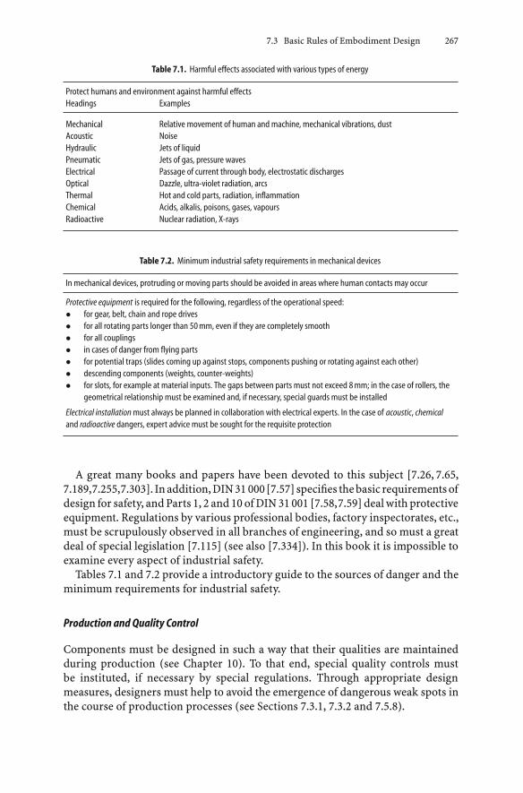
7.3 Basic Rules of Embodiment Design 267
Table 7.1. Harmful effects associated with various types of energy
Protect humans and environment against harmful effectsHeadings Examples
Mechanical Relative movement of human and machine, mechanical vibrations, dustAcoustic NoiseHydraulic Jets of liquidPneumatic Jets of gas, pressure wavesElectrical Passage of current through body, electrostatic dischargesOptical Dazzle, ultra-violet radiation, arcsThermal Hot and cold parts, radiation, inflammationChemical Acids, alkalis, poisons, gases, vapoursRadioactive Nuclear radiation, X-rays
Table 7.2. Minimum industrial safety requirements in mechanical devices
In mechanical devices, protruding or moving parts should be avoided in areas where human contacts may occur
Protective equipment is required for the following, regardless of the operational speed:• for gear, belt, chain and rope drives• for all rotating parts longer than 50mm, even if they are completely smooth• for all couplings• in cases of danger from flying parts• for potential traps (slides coming up against stops, components pushing or rotating against each other)• descending components (weights, counter-weights)• for slots, for example at material inputs. The gaps between parts must not exceed 8mm; in the case of rollers, the
geometrical relationship must be examined and, if necessary, special guards must be installed
Electrical installation must always be planned in collaboration with electrical experts. In the case of acoustic, chemicaland radioactive dangers, expert advice must be sought for the requisite protection
A great many books and papers have been devoted to this subject [7.26, 7.65,7.189,7.255,7.303]. Inaddition,DIN31 000[7.57] specifies thebasic requirementsofdesign for safety, and Parts 1, 2 and 10 of DIN 31 001 [7.58,7.59] deal with protectiveequipment. Regulations by various professional bodies, factory inspectorates, etc.,must be scrupulously observed in all branches of engineering, and so must a greatdeal of special legislation [7.115] (see also [7.334]). In this book it is impossible toexamine every aspect of industrial safety.
Tables 7.1 and 7.2 provide a introductory guide to the sources of danger and theminimum requirements for industrial safety.
Production and Quality Control
Components must be designed in such a way that their qualities are maintainedduring production (see Chapter 10). To that end, special quality controls mustbe instituted, if necessary by special regulations. Through appropriate designmeasures, designers must help to avoid the emergence of dangerous weak spots inthe course of production processes (see Sections 7.3.1, 7.3.2 and 7.5.8).

268 7 Embodiment Design
Assembly and Transport
The loads to which a product will be subjected during assembly and transport mustbe taken into consideration during the embodiment design phase. Welds carriedout during assembly must be tested and, where necessary, heat treated. All majorassembly processes should, whenever possible, be concluded by functional checks.
For safe transportation, firm bases, support points and handling points shouldalways be provided and marked clearly. The weights of parts heavier than l00 kgshould be marked where they can be seen easily. If frequent dismantling is calledfor, the appropriate lifting points must be incorporated.
Operation
Operation and handling must be safe [7.57, 7.58]. The failure of any automaticdevice must be indicated at once so that the requisite actions can be taken.
Maintenance
Maintenance and repair work must only be undertaken when the machine is shutdown. Particular care is needed to ensure that assembly or adjusting tools are notleft behind in the machine. Safety switches must ensure that the machinery is notstarted unintentionally. Centrally placed, easily accessible and simple service andadjustment points should be provided. During inspection or repair, safe accessshould be possible through the provision of handrails, steps, nonslip surfaces, etc.
Costs and Schedules
Cost and schedule requirements must not affect safety. Cost limits and deliverydates are ensured by careful planning, and by implementing the correct conceptsand measures, not by cutting corners. The consequences of accidents and failuresare generally much greater and graver than the effort needed to prevent them.
7.4 Principles of Embodiment Design
The general principles of embodiment design have been discussed at some lengthin the literature. Kesselring [7.148] set out principles of minimum productioncosts, minimum space requirements, minimum weight, minimum losses, and op-timum handling (see Section 1.2.2). Leyer discussed the principle of lightweightconstruction [7.167] and the principle of uniform wall thickness [7.168]. It is obvi-ously neither possible nor desirable to have all of these principles implemented inevery technical solution—one of them might be crucial, the rest merely desirable.Which principle should be prioritised in a given case can only be deduced fromthe task and the company’s facilities. By proceeding systematically, elaboratinga requirements list, abstracting to identify the crux of the problem, and also by

7.4 Principles of Embodiment Design 269
following the checklist given in Figure 5.3, designers transform these principlesinto concrete proposals that enable them to determine production costs, spacerequirements, weights, etc. These have to be consistent with the requirements list.
The systematic approach also highlights the question of how, with a givenproblem and a fixed solution principle, a function can be best fulfilled and bywhich type of function carrier. Embodiment design principles facilitate this partof the design process. In particular, they help with Steps 3 and 4, but also withSteps 7 to 9 as listed in Section 7.1.
Initially embodiment problems focus predominantly on issues of channelling,combining and storing. For the relatively common task of transmitting (chan-nelling) forces or moments, it seems advisable to establish special “principles offorce transmission”. Changing the type or varying the magnitude of a force areprimarily fulfilled by the appropriate physical effects, but designers must also applythe “principle of minimum losses” [7.148] for energy conservation or economicreasons, which they do by adopting a small number of highly efficient steps. Thisprinciple also applies to the efficient conversion of one type of energy into another,whenever this should be required. Storing energy involves the accumulation ofpotential and kinetic energy, be it directly or indirectly through the collectionof material. The storage of energy, however, raises the question of the stabilityof the system, and the consequent application of the “principles of stability andbi-stability”.
Often, several functions have to be fulfilled by one or several function carriers.Here the “principle of the division of tasks” may be useful to designers. Its appli-cation involves careful analysis of the functions and their assignment to functioncarriers. This analysis of functions is also helpful for the application of the “prin-ciple of self-help” when supplementary effects must be identified and exploited.
When applying embodiment design principles, designers may find that theyrun counter to certain requirements. Thus, the principle of uniform strengthmay conflict with the demand for minimum costs; the principle of self-help mayconflict with fail-safe behaviour (see Section 7.3.3); and the principle of uni-form wall thickness chosen for the purpose of simplifying the production process[7.168] may conflict with the demand for lightweight construction or uniformstrength.
These principles represent many strategies that are only applicable under certainconditions. In using them, designers must strike a balance between competingdemands. To that end, the present authors have developed what they consider tobe important embodiment design principles, which will now be presented. Mostare based on energy flow considerations and, by analogy, they apply equally wellto the flow of material and of signals.
7.4.1 Principles of Force Transmission
1. Flowlines of Force and the Principle of Uniform Strength
The problems solved in mechanical engineering generally involve forces and/ormotions and their connection, change, variation or channelling, and involve the
270 7 Embodiment Design
conversion of energy, material and signals. The generally applicable function“channel forces” includes the application of loads to, the transfer of forces be-tween, and the transmission of forces through components and devices. Guide-lines are provided in [7.168, 7.278]. In general, designers should try to avoid allsudden changes of direction in the flowlines of force—that is, in the force trans-mission path—caused by sharp deflections and abrupt changes of cross-section.The idea of “flowlines of force” aids the visualisation of the force transmissionpaths (load paths) through components and devices, and is analogous to flowlinesin fluid mechanics. Leyer [7.167, 7.168] has dealt with the transmission of forcesat some length, so we can dispense with a detailed discussion of the problem.Designers are advised to consult these important texts. Leyer, moreover, empha-sises the complex interaction between the functional, embodiment and productionaspects. The concept of force transmission can be summarised as described be-low.
Force transmission must be understood in a broad sense; that is, it must includethe application, transfer and transmission of bending and twisting moments.First, it is important to remember that external loads applied to a componentproduce axial and transverse forces as well as bending and twisting momentsat every section. These set up stresses (direct and shear) that produce elastic orplastic deformations (longitudinal, lateral (Poisson), and shear strains, along withbending and twisting).
The section dimensions transmitting the forces are obtained by “mental dis-section” of the components at the point under consideration. The sum of thestresses over these sections produces internal forces and moments which must bein equilibrium with the external loads.
The stresses, determined at the relevant section, are then compared with the ma-terial properties of tensile strength, yield strength, fatigue strength, creep strength,etc., with due regard being paid to stress concentrations, surface finish and sizeeffects.
The principle of uniform strength [7.278] aims, with the help of appropriate ma-terials and shapes, to achieve uniform strength throughout a mechanical deviceover its anticipated operational life. Like the principle of lightweight construc-tion [7.167], it should be applied whenever economic circumstances allow.
This important consideration often misleads designers into neglecting the de-formations (strains) associated with the stresses. It is, however, these very defor-mations that often throw light on the behaviour of components and tell us whatwe need to know about their integrity (see Section 7.4.1).
2. Principle of Direct and Short Force Transmission Path
In agreement with Leyer [7.168,7.208] we consider the following principle to be ofgreat importance:
• If a force or moment is to be transmitted from one place to another withthe minimum possible deformation, then the shortest and most direct forcetransmission path is the best.

7.4 Principles of Embodiment Design 271
This principle, which leads to the minimum number of loaded areas, ensures:
• minimum use of material (volume, weight)
• minimum deformation.
This is particularly true if it is possible to solve a problem using tensile or compres-sive stresses alone, because these stresses, unlike bending and torsional stresses,produce smaller deformations. When a component is in compression, however,special attention must be paid to the danger of buckling.
If, on the other hand, we require a flexible component capable of considerableelastic deformation, then a design using bending or torsional stresses is generallythe more economical.
The principle is illustrated in Figure 7.27—the mounting of a machine frameon a concrete foundation—where different requirements demand supports withdifferent stiffnesses. This, in turn, has repercussions on the operational behaviourof the machine: different natural and resonant frequencies, modified responseto additional loads, etc. The more rigid solutions are obtained with minimummaterial and space requirements by means of a short support under compression;the most flexible solution by means of a spring, which transmits the force in torsion.If we look at other design solutions, we find many examples of the same principle:for example, in the torsion bar springs of motor cars, or in flexible pipes that relyon bending or torsional deformations.
The choice of means thus depends primarily on the nature of the task; thatis, on whether the force transmission path must be designed for durability with
Figure 7.27. Supporting a machine frame on a concrete foundation: a very rigid support due to short force transmissionpath and low stress on the baseplates; b longer force transmission path, but still a rigid support with tubes or box sectionsunder compression; c less rigid support with pronounced bending deformation (a stiffer construction would involve thegreater use of materials); d more flexible support under bending stresses; e very flexible support using a spring, whichtransmits the load in torsion. This can be used to alter the resonance characteristics

272 7 Embodiment Design
Figure 7.28. Force deformation diagram of tough materials. Arrows indicate the cause–effect relationships
maximum stiffness, or whether certain force–deformation relationships must besatisfied first and durability can be treated as a subsidiary problem.
If the yield point is exceeded, then the following have to be taken into consider-ation (see Figure 7.28):
• When a component is loaded by a force, it is invariably subjected to deformation.If the yield point is exceeded, then the linear-elastic relationship between theforce and the deformation no longer holds. Relatively small changes in the forcenear the peak of the force–deformation curve may produce unstable conditionsleading to fracture, because the load-bearing cross-section may be reduced morerapidly than the strength is increased due to strain hardening. Examples are tierods, centrifugal inertia forces on a disc, and weights on a rope. The necessarysafety precautions must always be taken.
• When a component is deformed, then a reaction force is set up. So long asthe impressed deformation does not change, the force and the stress remainunchanged as well. If the peak is not reached, the component remains stable sothat the yield point can be exceeded without danger. Beyond the yield point,a large change in deformation will lead to only a small change in the force.Admittedly, any preload must not be augmented with further operational loadsin the same sense, otherwise the conditions described above will prevail. Furtherrequirements are the use of tough materials and the avoidance of a build-up ofmultiaxial stresses in the same sense. Examples are highly distorted shrink-fits,preloaded bolts and clamps.
3. Principle of Matched Deformations
Designs matched to the flowlines of force avoid sharp deflections of the trans-mission path and sudden changes in cross-section, thus preventing the unevendistribution of stresses with high stress concentrations. A visualisation of the flow-

7.4 Principles of Embodiment Design 273
lines of force, though very graphic, does not always reveal the decisive factorsinvolved. Here, too, the key is the deformation of the affected components.
The principle of matched deformations states that related components must bedesigned in such a way that, under load, they will deform in the same sense and, ifpossible, by the same amount.
As an example, let us take soldered or glued connections in which the solder oradhesive layer has a different modulus of elasticity from that of the material to bejoined. Figure 7.29a illustrates the resulting deformation [7.181]. The deformationsand the thickness of the solder or adhesive layers have been greatly exaggerated.The load F, which is transmitted across the junction of parts 1 and 2, producesdistinct deformations in the overlapping parts, the adhesive layer being subjectedto particularly marked deformation near the edges due to differences in the relativedeformation of parts 1 and 2. While part 1 bears the full load F at the upper edgeof the adhesive layer and is therefore stretched, part 2 does not yet bear a load.The relative shift in the adhesive layer sets up a local shear stress that exceeds thecalculated mean value.
A particularly unsatisfactory result is shown in Figure 7.29b where, as a resultof opposite and unmatched deformations of parts 1 and 2, the deformation in theadhesive layer is considerably increased. This example makes it clear why provisionshould be made for deformations to take place in the same sense and, if possible,to be equal in magnitude. Magyar [7.177] has made a mathematical study of therelationships between load and shear stress: the result is shown qualitatively inFigure 7.30.
The same phenomenon also occurs between nuts and bolts in boltedjoints [7.328]. The nut (see Figure 7.31a) is in compression and the bolt is intension, that is, they are deformed in the opposite sense. In the modified nut (see
Figure 7.29. Overlapping adhesive or solder joint with strongly exaggerated deformation from [7.181]: a Parts 1 and 2deformed in the same sense; b Parts 1 and 2 deformed in the opposite sense

274 7 Embodiment Design
Figure 7.30. Distribution of forces and shear stresses in overlapping joints with layer of adhesive or solder, after [7.177]:aoverlappedonone side (bending stress neglected);b splicedwith linearly decreasing thickness;cpronounced “deflectionof the flowlines of force” with deformations in the opposite sense (bending stress neglected)
Figure 7.31b) a deformation in the same sense is set up in the leading threads,which gives rise to a smaller relative deformation and hence a more even distri-bution of the load borne by individual threads. Wiegand [7.328] has been ableto demonstrate this effect by showing that such nuts have a longer service life.Paland [7.214] has shown more recently that standard nuts are not as unsatis-factory as Maduschka [7.175] has suggested, because the moment F · h producesadditional outward deformations of the nut at the contact surface and thus relievesthe leading threads of their load. The load-relieving deformation of the nut dueto this moment and also to the bending of the threads can be increased consid-erably by using material with a lower modulus of elasticity. If, on the other hand,the load-relieving deformations are resisted by a very stiff nut or a very smalllever arm h, then the type of load distribution described by Maduschka wouldensue.
As a further example, let us take a shaft–hub connection formed by a shrink fit.In essence, this too involves the deformation of two components [7.125]. In trans-mitting the torque, the shaft experiences a torsional deformation that decreases asthe torque is transferred to the hub. The hub, for its part, is deformed in accordancewith the transmitted torque.
Figure 7.32a shows that the maximum relative deformation occurs at A. In thecase of alternating torques, this may lead to fretting corrosion; moreover, the right-

7.4 Principles of Embodiment Design 275
Figure 7.31. Nut shapes and load distribution, after [7.328]: a standard nut: limiting case after Maduschka [7.175] andcase after Paland [7.214] allowing for deformation due to moment F · h; b modified nut with matched deformations in thetension part
hand end, to all intents and purposes, contributes nothing to the transfer of thetorque.
The solution shown in Figure 7.32b is much better because the resulting de-formations are in the same sense. The best solution appears when the torsionalstiffness of the hub is matched to that of the shaft. The transfer of torque then takesplace along the whole length of the connection, ensuring uniform distribution offorce flowlines and thus avoiding stress concentrations.
Even if the shrink fit were replaced with a keyed connection, the layout depictedin Figure 7.32a would, because the torsional deformations are in the opposite sense,set up very high contact stresses in the neighbourhood of A. The layout depictedin Figure 7.32b will, on the other hand, ensure an even contact stress distributionbecause the deformations are in the same sense [7.188].
The principle of matched deformations can also be applied to bearings, as inFigure 7.33. The embodiment of the bearings should ensure matched deformationsbetween bearing and shaft, or provide for adjustment possibilities.

276 7 Embodiment Design
Figure 7.32. a Shaft–hub connection with strong “force flowline deflection”. Torsional deformations of shaft and hub inoppositesense(ψ=angleof twist).bShaft–hubconnectionwithgradual “force flowlinedeflection”.Torsionaldeformationsof shaft and hub in the same sense
Figure 7.33. Force transmission in bearings: a edge compressing because of insufficient adaptation of the bearing tothe deformed shaft; b more even bearing pressure because of matched deformations; c lacking adjustment to shaftdeformation; d more even bearing pressure because of adaptability of bearing bush
The principle of matched deformations must be taken into account, not onlyin the transfer of forces from one component to another, but also in the divisionor combination of forces or moments. A well-known problem is the simultaneouspropulsion of wheels that have to be placed at a considerable distance from one an-other, for instance incranedriveassemblies. In the layout shown inFigure7.34a, theleft side has a relatively high torsional stiffness due to the short force transmissionpath, and the right side a relatively low torsional stiffness because of its greater pathlength. When the torque is first applied, the left wheel will be set in motion, whilethe right wheel remains stationary until the right hand part of the shaft has twistedsufficiently to transmit the torque. The drive assembly has a tendency to run skew.
It is essential to provide the same torsional stiffness to both parts of the shaftso as to ensure an appropriate division of the initial torque. This can be achieved

7.4 Principles of Embodiment Design 277
Figure 7.34. Application of the principle of matched—here equal—deformations in crane drives: a unequal torsionaldeformation of lengths l1 and l2 ; b symmetrical layout ensures equal torsional deformation; c asymmetrical layout withequal torsional deformation due to adaptation of torsional stiffnesses
in two distinct ways if the input torque is taken in one position only: either bysymmetrical layout (see Figure 7.34b); or by adaptation of the torsional stiffnessof the appropriate parts of the shaft (see Figure 7.34c).
4. Principle of Balanced Forces
Those forces and moments that serve the function directly, such as the drivingtorque, the tangential tooth force, and the load torque in a gearbox, can, in ac-cordance with the definition of a main function, be described as functionallydetermined main forces.
In addition, there are many forces or moments that do not serve the functiondirectly but that cannot be ignored, for instance:
• the axial force produced by a helical gear
• the force resulting from a pressure difference, for instance across the blades ofa turbine or across a control valve
• tensile forces for producing a friction connection
• inertia forces due to linear acceleration or rotation of components
• fluid flow forces, inasmuch as they are not the main forces.
Such forces and moments accompanying the main ones are called associated forces,and may either produce a useful auxiliary effect or else appear merely as anunwanted effect that has be taken into account.

278 7 Embodiment Design
Associated forces place additional loads on the components and require anappropriate layout, or must be taken up by further surfaces and elements, suchas stiffening members, collars, bearings, etc. As a result, weights are increasedand further frictional losses may be incurred. For that reason, the associatedforces must, whenever possible, be balanced out at their place of origin, thusobviating the need for a heavier construction or for reinforced bearing and transferelements.
As has been shown in [7.204], this balance of forces is essentially ensured by twotypes of solution:
• balancing elements
• symmetrical layout.
Figure 7.35 shows how the associated forces can be balanced in a turbine, helicalgears and a cone clutch, with the help of the principle of direct and short force
Figure 7.35. Fundamental solutions for balancing associated forces, illustrated via a turbine, helical gears and cone clutch

7.4 Principles of Embodiment Design 279
transmission path. As a result, no bearing position is loaded additionally and thedesigns are highly economical.
When it comes to the balancing of inertia forces, we find that a rotationally sym-metrical layout is inherently balanced. The same solution principle is applied forreciprocating masses, as we know from automobile engineering. If the number ofcylinders is too small to ensure a perfect balance, either special balancing elements,weights or shafts [7.228] are introduced, or cylinders are arranged symmetrically,as for instance in opposed cylinder engines.
As a general rule (which, however, can be ignored if there are overriding reasonsfor doing so), balancing elements should be chosen for relatively small or mediumforces, and a symmetrical layout for relatively large forces.
5. Summary of Force Transmission Principles
Earlier we discussed the value of using the descriptive idea of flowlines of forcewhen considering the transmission of forces during the embodiment of assembliesand components. The flowlines should fulfil the following criteria:
• the flowlines must always be closed
• the flowlines should, in general, be as short as possible, which can best beachieved by direct force transmission
• sharp deflections of the flowlines and changes in their “density” resulting fromsudden changes in cross-section must be avoided.
In the case of complex force transmission situations, the definition or visualisationof a flowline envelope can be useful. This is the working zone outside of which theforces have no effect. The smaller the envelope, the shorter the force transmissionpaths. Figure 7.36 shows different concepts of a rotary bending test rig with therespective flowlines envelopes indicated.
The following principles complement the concept of flowlines:
• The principle of uniform strength which ensures, through the careful selectionof materials and shapes, that each component is of uniform strength and con-tributes equally to the overall strength of a device throughout its service life.
• Theprincipleofdirectand short force transmissionpath,whichensuresminimumvolume, weight and deformation, and which should be applied particularly ifa rigid component is needed.
• The principle of matched deformations, which ensures the matching of deforma-tions of related components, so that stress concentrations are avoided and thefunction can be reliably fulfilled.
• The principle of balanced forces, which ensures, with the help of balancingelements or a symmetrical layout, that the associated forces accompanying themain ones are reacted as close as possible to their place of origin, so that materialquantities and losses can be kept to a minimum.
In many situations, these principles cannot be applied to their full extent and oftenhave to be applied in combination.

280 7 Embodiment Design
Figure7.36. Force flow envelope (working zone of the forces) for a rotary bending test rig [7.330].aWorking zone includesthe foundations; b working zone includes the supports; c working zone excludes the supports; d the test rig actuallybuilt using principle c, but with magnetic force excitation: 1 test shaft, 2 mounting flange, 3 connector, 4 support arm,5 foundation supports, 6 magnet pair

7.4 Principles of Embodiment Design 281
7.4.2 Principle of the Division of Tasks
1. Assignment of Subfunctions
Even during the setting up and variation of the function structure, it is importantto determine to what extent several functions can be replaced by a single one, orwhetherone functioncanbe subdivided into several subfunctions (see Section 6.3).
These questions reappear in the embodiment phase, when the problem is tofulfil the requisite functions with the choice and assignment of suitable functioncarriers. We ask:
• Which subfunctions can be fulfilled with one function carrier only?
• Which subfunctions must be fulfilled with the help of several, distinct functioncarriers?
So far as the number of components and the space and weight requirements areconcerned, a single function carrier fulfilling several functions would, of course,be the best. In terms of the production and assembly processes, however, this mayprove disadvantageous, if only because of the complicated shape of the resultingcomponent. Nevertheless, for economic reasons, an attempt should always be madeto fulfil several functions with a single function carrier.
Numerous assemblies and components can fulfil several functions simultane-ously or successively, as in the following examples:
• A shaft on which a gearwheel has been mounted transfers the torque and therotating motion simultaneously, and, at the same time, takes up the bendingmoments and shear forces resulting from the normal tooth force. It also locatesthe gears axially and, in the case of helical gears, carries the axial force compo-nents from the teeth. In conjunction with the body of the gearwheel, it providessufficient stiffness to ensure correct mating of the teeth.
• A pipe flange connection makes the connection and separation of the pipespossible, ensures the sealing of the joint, and transmits all forces and momentsin the pipe resulting from residual tension, from thermal expansion and fromunbalanced pipe loads.
• A turbine casing provides the appropriate inlet and outlet flow areas for the fluid,provides a mounting for the stationary blades, transmits the reaction forces tothe foundation, and ensures a tight seal.
• A wall of a pressure tank in a chemical plant must combine a retaining witha sealing functionandstaveoff corrosion,whilenot interferingwith the chemicalprocess.
• A deep groove ball bearing, apart from its centering task, transmits both radialand axial forces and occupies a relatively small volume.
The combination of several functions in a single function carrier may often proveeconomically advantageous, but may have certain drawbacks. These do not usuallyappear unless:

282 7 Embodiment Design
• the capacity of the function carrier has to be increased to the limit with respectof one or several functions
• the behaviour of the function carrier must be kept absolutely constant in oneimportant respect.
As a rule, it is impossible to optimise the carrier of several combined functions.Instead, designers have recourse to the principle of the division of tasks [7.207],by which a special function carrier is assigned to every function. Moreover, inborderline cases, it may even be useful to distribute a single function over severalfunction carriers.
The principle of the division of tasks:
• allows much better exploitation of the component concerned
• provides for greater load capacity
• ensures unambiguous behaviour, and hence fosters the basic rule of clarity (seeSection 7.3.1).
This is because the separation of tasks facilitates optimum design in respect toevery subfunction and facilitates more accurate calculations. In general, however,the constructional effort becomes correspondingly greater.
To determine whether the principle of the division of tasks can be usefullyapplied, the functions must be analysed with a view to determining if the simul-taneous fulfilment of several functions in one carrier introduces constraints ormutual interferences. If it does, then it is best to settle for individual functioncarriers.
2. Division of Tasks for Distinct Functions
Examples from various fields illustrate the advantage of the division of tasks fordistinct functions.
In large gearboxes, as found for instance between a turbine and a generator, it isadvisable, because of thermal expansion of the foundations and bearings and alsobecause of the torsional oscillations, to use a radially and torsionally flexible shaftwhilst maintaining the shortest possible axial length on the output side [7.203].However, because of the forces between the gear teeth, the transmission shaft mustbe as rigid as possible. Here the principle of the division of tasks leads to thefollowing arrangement: the gearwheel is fitted to a stiff hollow outer shaft with theshortest possible distance between the bearings, while the radially and torsionallyflexible component takes the form of an inner torsion shaft (see Figure 7.37).
Modern pressure-fed boilers are built with a membrane wall, as shown inFigure 7.38. The furnace must be gas-tight. Moreover, optimum heat transferto the water demands thin walls with large surface areas. Beyond that, thermalexpansion and pressure differences between the furnace and its environment mustalso be taken into consideration, and so must the weight of the walls. This complexproblem is solved with the help of the principle of the division of tasks. The tubu-lar walls with their welded lips constitute the sealed furnace. The forces resulting

7.4 Principles of Embodiment Design 283
Figure 7.37. Large gearbox with an output torsion shaft; the bearing forces are transmitted over a stiff hollow shaft; theinner torsion shaft is radially and torsionally flexible, after [7.203] (Siemens-Maag)
from the pressure differences are transferred to special supports outside the heatedarea, which also carry the weight of the—usually suspended—walls. Articulatedarms between the tubular wall and the supports allow for unimpeded thermalexpansion. Thus every part can be designed in accordance with its special task.
The clamp connection in a superheated steam pipe shown in Figure 7.39 has alsobeen designed based on the principle of the division of tasks. The sealing and load-carrying functions are assigned to different function carriers: the sealing functionis performed by the welded membrane seal, which is axially loaded by the tensionin the clamp. Tensile forces or bending moments should not be carried by the seal,whose function and durability would thereby be destroyed, so the load-carryingfunction is performed by the clamp which, in turn, is designed on the principleof the division of tasks. The clamp is made up of segments, which transmit forcesand bending moments by means of a close-tolerance fit, and shrink rings hold theclamp segments together via friction in a simple and effective manner. Every partcan he optimally designed for its particular task and is easily analysed.
The casings of turbines must ensure a tight seal under all operational andthermal conditions if they are to conduct the working fluid with minimum lossand turbulence. They must also provide an annular area and a support for thestationary blades. During temperature changes, sectioned casings with an axialflange have a particular tendency to distort and to lose sealing power due to

284 7 Embodiment Design
Figure 7.38. Section of boiler with membrane walls and separate supports (Babcock)
marked changes in shape at the inlet and outlet [7.224]. This effect can be offsetby a separate blade carriers, that is, by a division of tasks. The annular area andstationary blade attachment can be designed regardless of the larger casing withits inlet and outlet sections. The outer casing can then be designed exclusively fordurability and sealing (see Figure 7.40).
A further example is provided by the synthesis of ammonia, which involvesfeeding nitrogen and hydrogen into a container under high pressures and tem-peratures. If the hydrogen were allowed to come into direct contact with a ferriticsteel container, it would penetrate into and decarbonise the latter, producing de-composition at the grain boundaries with the formation of methane [7.117]. Thesolution is again based on the division of tasks. The sealing function is providedby an inner casing of austenitic steel which is resistant to hydrogen, while supportand strength are provided by a surrounding pressure chamber constructed fromhigh-tensile ferritic steel, which is not resistant to hydrogen.

7.4 Principles of Embodiment Design 285
Figure 7.39. Clamp connection in a superheated steam pipe (Zikesch)
Figure 7.40. Axially divided turbine housing, after [7.224]: lower half conventional; upper half with separate blade carrier
In the electrical circuit-breaker illustrated in Figure 7.41, two or even threecontact systems are provided. The breaker contacts 1 take the arcing current duringthe closing or opening of the switch, and the main contacts 3 carry the currentunder normal conditions. The breaker contacts 1 are subject to burning—that is,to wear and tear—and must be designed accordingly, while the main contacts mustbe designed to carry the full working current.
The division of tasks is also illustrated in Figure 7.42: the Ringfeder connectorscarry the torque, while the corresponding cylindrical surfaces ensure the centrallocation and seating of the pulley, which the Ringfeder connector cannot provideby itself when high accuracy is required.
A further example is provided by the design of rolling element bearings in whichthe service life of the locating bearing is increased by the clear separation of thetransmission paths of radial and axial forces (see Figure 7.43). The outer race ofthe deep-groove ball bearing is not supported radially, and hence transmits axialforces only, while the roller bearing transmits radial forces only.

286 7 Embodiment Design
Figure 7.41. Arrangement of contacts in a circuit breaker (AEG): 1 breaker contacts; 2 intermediate contacts; 3 maincontacts
Figure 7.42. Ringfeder connector plus centralising surfaces
The principle of the division of tasks has been applied consistently to the con-struction of composite flat belts. They are made up, on the one hand, of a syntheticmaterial capable of carrying high tensile loads and, on the other hand, of a chromeleather layer on the contact surface which provides a high coefficient of frictionfor the transfer of the load.
Yet another example is provided by the rotor blade attachment in a helicopter(see Figure 7.18).

7.4 Principles of Embodiment Design 287
Figure 7.43. Locating bearing with separate transmission paths for radial and axial forces
3. Division of Tasks for Identical Functions
If increases in load or size reach a limit, a single function can be assigned toseveral, identical function carriers. In other words, the load can be divided andthen recombined later. There are numerous examples of this.
The load capacity of a V-belt cannot be increased at will by increases in its cross-section (number of load-carrying strands per belt) because, for a given pulleydiameter, an increase in the belt height h (see Figure 7.44) leads to an increase inthe bending stress. As a result of the ensuing deformation, the rubber (which hashysteresis properties and is also a poor conductor of heat) becomes overheatedand this reduces its life. A disproportionally wide belt, on the other hand, loses thestiffness needed to take up the normal forces acting on the wedge-shaped surfacesof the pulley. An increase in load-carrying capacity can, however, be obtained bydividing the overall load into part loads, each appropriate to the load limit andnormal life of the individual belts (multiple arrangement of parallel V-belts).
The coefficient of thermal expansion of superheated steam pipes made ofaustenitic steel is approximately 50% higher than that of pipes made of the usualferritic steel. Such pipes, moreover, are particularly stiff. At constant inner pres-sures and fixed material property limits, the ratio of outer to inner pipe diameterremains constant if the inner diameter is changed. However, while the throughputat constant flow velocities varies as the square of the inner diameter, the bendingand torsional stiffnesses vary as its fourth power. The substitution of z pipe linesfor a single large pipe would admittedly lead to increased pressure and heat lossesfor the same flow area, but would reduce the stiffness resisting thermal expansionby 1/z. With four or eight pipelines, the individual reaction forces would then beno more than 1/4 or 1/8 of that present in a single pipe [7.29, 7.279]. In addition,the reduction in wall thickness leads to a reduction in thermal stresses.
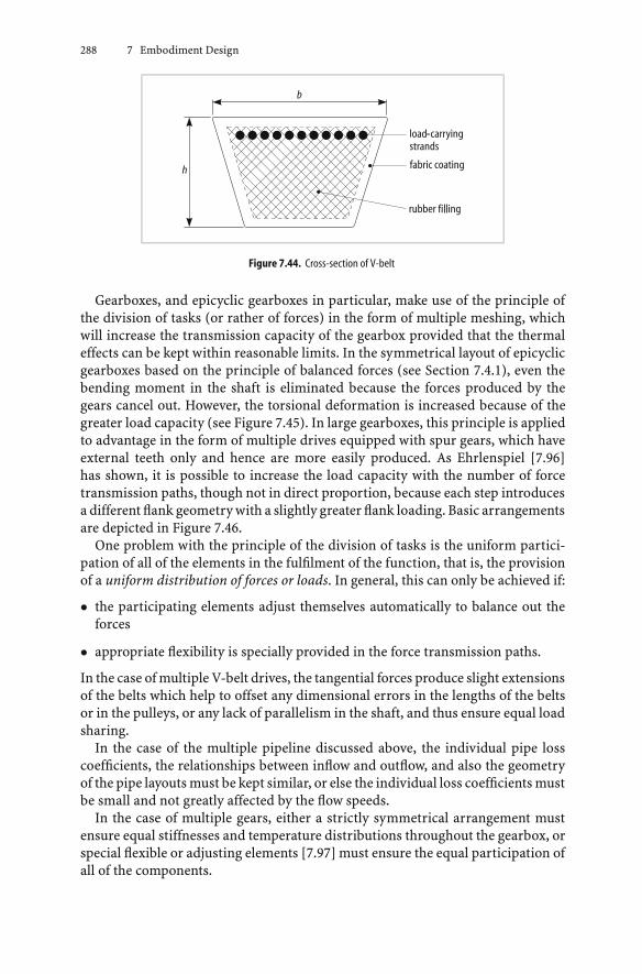
288 7 Embodiment Design
Figure 7.44. Cross-section of V-belt
Gearboxes, and epicyclic gearboxes in particular, make use of the principle ofthe division of tasks (or rather of forces) in the form of multiple meshing, whichwill increase the transmission capacity of the gearbox provided that the thermaleffects can be kept within reasonable limits. In the symmetrical layout of epicyclicgearboxes based on the principle of balanced forces (see Section 7.4.1), even thebending moment in the shaft is eliminated because the forces produced by thegears cancel out. However, the torsional deformation is increased because of thegreater load capacity (see Figure 7.45). In large gearboxes, this principle is appliedto advantage in the form of multiple drives equipped with spur gears, which haveexternal teeth only and hence are more easily produced. As Ehrlenspiel [7.96]has shown, it is possible to increase the load capacity with the number of forcetransmission paths, though not in direct proportion, because each step introducesa different flank geometry with a slightly greater flank loading. Basic arrangementsare depicted in Figure 7.46.
One problem with the principle of the division of tasks is the uniform partici-pation of all of the elements in the fulfilment of the function, that is, the provisionof a uniform distribution of forces or loads. In general, this can only be achieved if:
• the participating elements adjust themselves automatically to balance out theforces
• appropriate flexibility is specially provided in the force transmission paths.
In the case of multiple V-belt drives, the tangential forces produce slight extensionsof the belts which help to offset any dimensional errors in the lengths of the beltsor in the pulleys, or any lack of parallelism in the shaft, and thus ensure equal loadsharing.
In the case of the multiple pipeline discussed above, the individual pipe losscoefficients, the relationships between inflow and outflow, and also the geometryof the pipe layouts must be kept similar, or else the individual loss coefficients mustbe small and not greatly affected by the flow speeds.
In the case of multiple gears, either a strictly symmetrical arrangement mustensure equal stiffnesses and temperature distributions throughout the gearbox, orspecial flexible or adjusting elements [7.97] must ensure the equal participation ofall of the components.

7.4 Principles of Embodiment Design 289
Figure 7.45. Epicyclic gearbox with balanced forces, after [7.97]
Figure 7.46. Basic arrangements of multiple gears, after [7.203]
Figure 7.47 illustrates a flexible arrangement. Further balancing components,such as elastic and articulated joints, are described in [7.97].
All in all, the principle of the division of tasks provides for increases in themaximum load capacity or for wider applications. By spreading tasks over severalfunction carriers, we also gain a clearer picture of the relationship between forcesand their effects, and, what is more, we can increase the output, provided onlythat a balanced division of forces is maintained by adjustable or self-regulatingelements.
In supporting structures (such as bearing supports) where force transmissionis divided, a more balanced load distribution can be achieved by adjusting thestiffness. During the stiffness analysis, the location and direction of the externalforces have to be considered carefully, because they influence the deformation
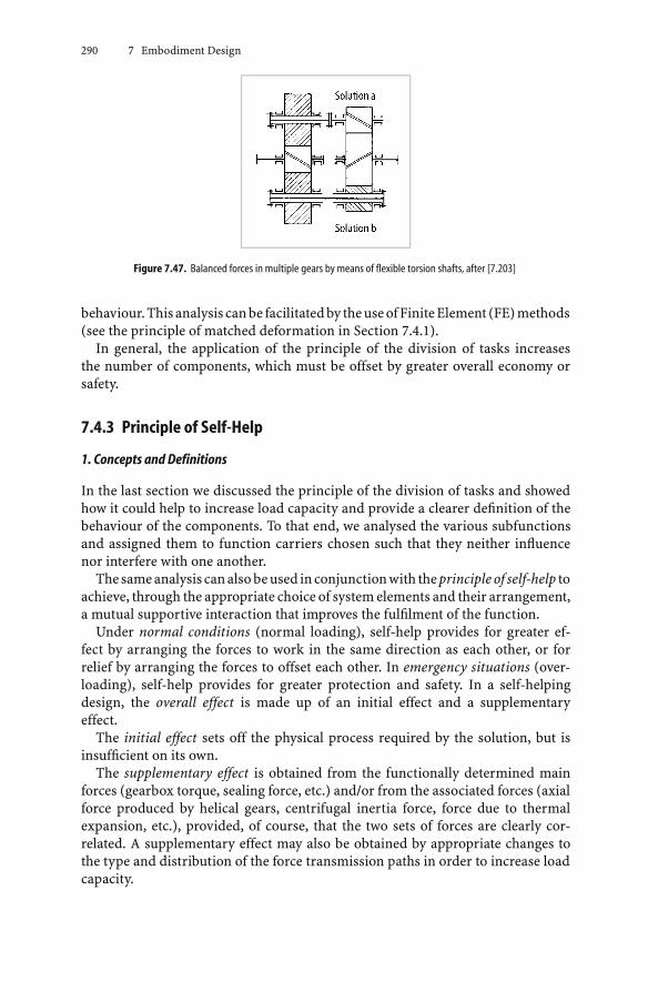
290 7 Embodiment Design
Figure 7.47. Balanced forces in multiple gears by means of flexible torsion shafts, after [7.203]
behaviour.This analysis canbe facilitatedby theuseofFiniteElement (FE)methods(see the principle of matched deformation in Section 7.4.1).
In general, the application of the principle of the division of tasks increasesthe number of components, which must be offset by greater overall economy orsafety.
7.4.3 Principle of Self-Help
1. Concepts and Definitions
In the last section we discussed the principle of the division of tasks and showedhow it could help to increase load capacity and provide a clearer definition of thebehaviour of the components. To that end, we analysed the various subfunctionsand assigned them to function carriers chosen such that they neither influencenor interfere with one another.
Thesameanalysis canalsobeused inconjunctionwith theprincipleof self-help toachieve, through the appropriate choice of system elements and their arrangement,a mutual supportive interaction that improves the fulfilment of the function.
Under normal conditions (normal loading), self-help provides for greater ef-fect by arranging the forces to work in the same direction as each other, or forrelief by arranging the forces to offset each other. In emergency situations (over-loading), self-help provides for greater protection and safety. In a self-helpingdesign, the overall effect is made up of an initial effect and a supplementaryeffect.
The initial effect sets off the physical process required by the solution, but isinsufficient on its own.
The supplementary effect is obtained from the functionally determined mainforces (gearbox torque, sealing force, etc.) and/or from the associated forces (axialforce produced by helical gears, centrifugal inertia force, force due to thermalexpansion, etc.), provided, of course, that the two sets of forces are clearly cor-related. A supplementary effect may also be obtained by appropriate changes tothe type and distribution of the force transmission paths in order to increase loadcapacity.

7.4 Principles of Embodiment Design 291
The idea of formulating the self-help principle was first suggested by theBredtschneider–Uhde self-sealing cover, which is particularly suitable for pressurevessels [7.237]. Figure 7.48 shows how it works. A relatively small force providedby the central bolt 2 suffices to press the cover 1 against the metal seal 5. The initialeffect of this force ensures that the parts make the proper contact. With increas-ing operational pressure, a supplementary effect is produced, which ensures thatthe sealing force between cover and tank is increased appropriately. The internalpressure thus provides the required sealing force automatically.
Inspired by this self-sealing solution, the principle of self-help was formulatedin [7.206, 7.209] and further analysed and elaborated by Kühnpast [7.161].
It may be useful to specify the quantitative contribution of the supplementaryeffect S to the overall effect O in producing the degree of self-help:
χ = S/O = 0…1
The gain from self-help solutions can be expressed in terms of one or severaltechnical characteristics: efficiency, service life, use of materials, technical limit,etc. The self-help gain is defined as:
γ =technical characteristic with self-help
technical characteristic without self-help
Whenever the application of the self-help principle calls for a greater effort on thepart of designers, then it must bring clear technical or economic advantages.
Identical design approaches may turn out to be self-helping or self-damaging,depending on the layout. Take the case of an inspection cover (see Figure 7.49). Solong as the pressure inside the tank is greater than the pressure outside, the layoutshown on the left is self-helping, because the pressure on the cover (supplementaryeffect) increases the sealing effect (overall effect) of the initial tension-screw force(initial effect).
Figure 7.48. Self-sealing cover: 1 cover; 2 central bolt; 3 cross member; 4 element with sawtooth thread, 5 metal sealingring; p = internal pressure, ϑ = temperature

292 7 Embodiment Design
The layout shown on the right, by contrast, is self-damaging because the pressureon the cover decreases the sealing effect O of the initial tension-screw force I. If,however, the tank were kept at below-atmospheric pressure, the left layout wouldbe self-damaging, the right layout self-helping (see also Figure 7.50).
This example shows that the degree of self-help depends on the resultant effect:in the present case the effect on the sealing force resulting from the elastic forces,and not on the simple addition of the force exerted by the screw and the force actingon the cover. Figure 7.50 can also be considered to be a force–deformation diagram
Figure 7.49. Layout of an inspection cover. I = initial effect; O = overall effect; p = internal pressure
Figure 7.50. Force diagram for Figure 7.49: F = forces; Fp = preload; ∆l = change in length; subscript t = tension screw;subscript f = flange/seal

7.4 Principles of Embodiment Design 293
Table 7.3. Summary of self-help solutions
Normal load Overload
Type of self-help Self-reinforcing Self-balancing Self-protecting
Supplementary effect Main and associated Associated forces Altered forcedue to forces transmission path
Important features Main or associated Associated forces act Force transmission pathforces act in the same in the opposite sense altered by elasticsense as other main to main forces deformation; limitationforces of function permissible
of a bolted connection with a preload and a working load. The conventional boltedflange connection may be called self-damaging inasmuch as, under operationalconditions, the overall effect—that is, the flange sealing—becomes smaller thanthe preload. Also, the loading of the bolts is increased at the same time. If possible,therefore, only self-reinforcing arrangements that increase the overall effect whilereducing the loading of the bolts should be chosen (Figs. 7.53a–d illustrate sucharrangements).
For practical purposes, it is useful to classify self-helping solutions in accordancewith Table 7.3.
2. Self-Reinforcing Solutions
In self-reinforcing solutions, the supplementary effect is obtained directly froma main or associated force and it adds to the initial effect to produce a greateroverall effect.
This group of self-helping solutions is the most common. Under part-loadconditions, it ensures greater service life, less wear, higher efficiency, etc., becausethe components are only loaded to an extent needed to fulfil the function at anyparticular moment.
As a first example, let us consider a continuously adjustable friction drive (seeFigure 7.51).
The preload spring a presses the freely movable cup wheel c on the drive shaft bagainst the cone wheel d, thus providing the initial effect. Once a torque is applied,the roller follower e attached to shaft b is pressed against the cam f formedon the cup wheel c, where it produces a normal force Fn that can be resolvedinto a tangential force Ft and an axial force Fa, which, for its part, increases thecontact force Fc applied to the cone wheel in a fixed proportion to the appliedtorque T:
Fa = T/(r · tan α)
The force Fa represents the supplementary effect gained from the torque. Theoverall effect is obtained from the spring preload force Fp plus the axial force Fa,

294 7 Embodiment Design
Figure 7.51. Continuously adjustable friction drive: a preload spring; b drive shaft; c cup wheel; d cone wheel; e rollerfollower; f cam formed on the cup wheel; r radius on which Ft and Fa act
which varies as the torque T (see Figure 7.52). The tangential driving force Fd onthe cone, which determines the transmittable torque, is therefore:
Fd = (Fp + Fa) · µ
and the degree of self-help is:
χ = S/O = Fa/(Fp + Fa)
It is obvious that the contact pressure between the wheels, which helps to de-termine the wear and the service life of the drive, must not exceed what isstrictly necessary. A conventional solution (no self-reinforcement) would havedemanded an axial force produced exclusively by the spring preload correspond-ing to the maximum torque, and would therefore have necessitated maximumpressure being applied to the contact area under all load conditions. As a result,the bearings would also have had to carry a considerably greater load, whichwould have led to a reduced service life or would have demanded a much heavierconstruction.
A rough calculation shows that if the actual loading is, say, 75% of the nominalmaximum load, then the bearing load would be reduced by about 20% which,because of the exponential relationship of service life to load, can lead to the life ofthe bearings being doubled. In that case, with n = 3 the self-help gain with respectto the service life becomes:
γL =Life with self-help
Life without self-help=
(C/0.8P
C/P
)n
= 1.253 = 2
A typical example is provided by the SESPA drive [7.157].

7.4 Principles of Embodiment Design 295
Figure 7.53 shows various self-reinforcing layouts of contact surfaces loaded bybolts, in which the frictional forces are increased by the operational forces whilethe bolts themselves are off-loaded.
The application of the principle of self-help in the design of self-reinforcingbrakes has been described by Kühnpast [7.161] and Roth [7.233]. Depending onthe application, even self-damaging—and in this case self-weakening—solutionscan prove interesting, inasmuch as they reduce the effect of variations of thecoefficient of friction on the braking moment [7.107, 7.233].
Figure 7.52. Degree of self-help (χ) and initial (I), supplementary (S) and overall (O) effect against the relative torqueT/Tmax for the friction drive (Figure 7.51)
Figure7.53. Self-helpingbolted connections:amultiple disc clutchwith adjustment ring;b force actingon theadjustmentring; c adjustable disc of two-disc friction clutch; d crown wheel attachment, symmetrical take-up of forces

296 7 Embodiment Design
Self-reinforcing seals (see Figure 7.54) provide us with further examples. Inthem, the operating pressure against which the seal has to be applied is used toproduce the supplementary effect.
Finally, we must mention one case in which the supplementary effect is producedby an associated force. In hydrostatic axial bearings, the centrifugal inertia effectleads to an increase in oil pressure which, at high revolutions, will help to improvethe load-carrying capacity, provided the heat can be removed (see Figure 7.55).The supplementary effect leads to an improvement in the load-carrying capacitydue to the increased oil pressure resulting from the centrifugal effect alone; theoverall effect is due to the load-carrying capacity of the combined static anddynamic pressures. According to Kühnpast [7.161], it should be possible at, say,166 rev/s and χ = 0.38, to obtain a gain in self-help of γ = 1.6 compared to staticconditions.
The supplementary effect of another associated force, namely that caused bythe effect of temperature on the shrink-fitted rings of a turbine, is discussedin [7.206].
Figure 7.54. Self-reinforcing seals: a self-sealing washer; b tubeless tyre; c radial shaft seal; d sleeve seal; e sliding ringseal
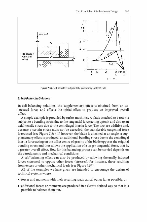
7.4 Principles of Embodiment Design 297
Figure 7.55. Self-help effect in hydrostatic axial bearings, after [7.161]
3. Self-Balancing Solutions
In self-balancing solutions, the supplementary effect is obtained from an as-sociated force, and offsets the initial effect to produce an improved overalleffect.
A simple example is provided by turbo-machines. A blade attached to a rotor issubject to a bending stress due to the tangential force acting upon it and also to anaxial tensile stress due to the centrifugal inertia force. The two are additive and,because a certain stress must not be exceeded, the transferable tangential forceis reduced (see Figure 7.56). If, however, the blade is attached at an angle, a sup-plementary effect is produced: an additional bending stress due to the centrifugalinertia force acting on the offset centre of gravity of the blade opposes the originalbending stress and thus allows the application of a larger tangential force, that is,a greater overall effect. How far this balancing process can be carried depends onthe aerodynamic and mechanical conditions.
A self-balancing effect can also be produced by allowing thermally inducedforces (stresses) to oppose other forces (stresses), for instance, those resultingfrom excess or other mechanical loads (see Figure 7.57).
All of the examples we have given are intended to encourage the design oftechnical systems where:
• forces and moments with their resulting loads cancel out as far as possible, or
• additional forces or moments are produced in a clearly defined way so that it ispossible to balance them out.

298 7 Embodiment Design
Figure7.56. Self-balancingsolution for turbineblades:aconventional solution;b leaningof thebladeproducesabalancingsupplementary effect due to the additional bending stresses produced by the centrifugal inertia force (σbC ), which opposethe bending stresses caused by the tangential force (σbT ); c diagram of forces
4. Self-Protecting Solutions
In general, in the event of an overload, we do not want components to be destroyed,unless of course they have been deliberately designed as weak links. In particular,we try to protect components that are frequently subject to slight overloads. Ifspecial safety arrangements, for instance to limit the load, are not essential, thena self-protecting solution may prove advantageous. It will sometimes be simplicityitself.
Self-protecting solutions derive their supplementary effect from an additionaldifferent force transmission path that, in case of excess loading, is generally cre-ated after a given elastic deformation has taken place. As a result, the distributionof the flowlines of force is altered, which changes the nature of the loading andthereby increases the load-carrying capacity. Admittedly, in that case, the func-tional properties associated with normal conditions may become altered, limitedor suspended.
The springs shown inFigure7.58have such self-protectingproperties. In the caseof excess loading, the spring elements, which are normally subject to torsional orbending stresses, will transmit the additional force directly by compressive stressestransmitted from coil to coil. The same effect may also be produced if the springsare shock-loaded (see Figure 7.58b).

7.4 Principles of Embodiment Design 299
Figure 7.57. Hoop stresses in a thick-walled cylinder due to the internal pressure σhp , and temperature differences atnearly steady heat flow σhth : a nonbalancing solution, thermal stress is added to the maximum mechanical stress on theinner surface; b self-balancing solution, thermal stress opposes maximum mechanical stress on the inner surface
Figure 7.59 shows the layout of elastic couplings in which restriction of the springmovements provides additional and different force transmission paths with con-sequent loss of flexibility but with increased load-carrying capacity. The originalsprings are removed from the force transmission path. In Figure 7.59a, the load-carrying capacity of the bar springs is altered inasmuch as, besides the normalbending, a powerful shear force between the two halves of the coupling appearswith overloads.
Figure 7.59b shows a coupling that, strictly speaking, may be considered a bor-derline case between a division of tasks and a self-protecting solution. The bufferswill only take up forces in the case of overloading. In this case, the nature of theloading on the spring elements remains unchanged, although the force transmis-sion path is altered after a given elastic deformation has taken place.
Kühnpast [7.161] also mentions cases in which there is an uneven stress dis-tribution over a cross-section, and where plastic deformation can then be usedfor purposes of self-protection. In such cases, however, sufficiently tough materi-als and adequate dimensional stability are needed, and additive multiaxial stresssituations are to be avoided.

300 7 Embodiment Design
Figure 7.58. Self-protecting solution in springs: a–d force transmission path changed, the normal function is suspendedor limited in the case of excess loading
Figure 7.59. Self-protecting solution in couplings; change of force transmission paths with loss of elastic properties incase of overloading: a bar–spring coupling; b elastic coupling with coil springs and special buffers to take up the force inthe case of overloading

7.4 Principles of Embodiment Design 301
It is hoped that the principle of self-help based on self-reinforcing, self-balancingand self-protecting solutions will encourage designers to examine every conceiv-able arrangement in an effort to arrive at an effective and economical solution.
7.4.4 Principles of Stability and Bi-Stability
We know the concepts of stable, neutral and unstable equilibrium from mechanics,as illustrated in Figure 7.60. When elaborating solutions, designers must alwaysconsider the effect of disturbances and try to keep the system stable by devisingmeans whereby the disturbances can be made to cancel out, or at least to mitigateone another. If disturbances are self-reinforcing, we have unstable or bi-stablebehaviour. This effect is desirable in certain solutions, where we speak of “plannedinstability”.
Figure 7.60. Characteristics of equilibrium states
1. Principle of Stability
By applying this principle, designers try either to ensure that disturbances cancelthemselves out or to reduce their particular effects. Reuter [7.225] has discussedthis subject at length and we shall now look at some of his examples.
In the design of pistons for pumps or regulating devices, the main objective is toachieve stable behaviour and minimum friction. Figure 7.61a shows the layout ofa piston with unstable characteristics. Disturbances due to, say, inaccuracies in thecylinder bore can tilt the piston slightly and produce pressure distributions overthe piston that encourage further tilting (unstable behaviour). Stable behaviour is

302 7 Embodiment Design
Figure7.61. Piston in cylinder, tilted due to a disturbance, after [7.225]:a resulting pressure distribution produces an effectthat increases the disturbance (unstable behaviour); b resulting pressure distribution produces an effect that opposes thedisturbance (stable behaviour)
Figure 7.62. Measures for improving the resulting pressure distribution, after [7.225]: a unstable behaviour mitigated bypressure-equalising grooves; b stable behaviour through conical piston; c through pressure pockets; d through joint fittedabove centre of gravity of the piston
ensured by the layout shown in Figure 7.61b, which, however, has a disadvantage:the piston rod inlet has to be sealed off on the pressure side.
According to [7.225], the layout shown in Figure 7.61a can be stabilised by themeasures shown in Figure 7.62a-d. They ensure that a disturbance will itself initiatepressure distributions that tend to correct the misalignment.
Another example is the well-known case of hydrostatic bearings with oil pocketsdistributed around the periphery. When the bearing is loaded, the leakage pathbelow the load is reduced, with the result that pressure builds up in the affectedoil pocket and decreases in the opposite one. Thanks to the combined effect, thebearing can take up the load with very small shaft displacement.
The stuffing boxes and seals of turbomachinery must always be designed forthermostable behaviour [7.225]. The seal of a turbocharger shown in Figure 7.63is a case in point. In the thermo-unstable layout (see Figure 7.63a), most of thefrictional heat generatedby contact forceswill flow into the rotor,which will heat upfurther, expand, and hence increase the contact forces. In the stable arrangement(see Figure 7.63b), in contrast, the frictional heat will cause the contact forces tobe reduced. A disturbance thus produces a self-limiting effect.
A similar approach is used in the design of taper roller bearings. Thus, in thelayout shown in Figure 7.64a, heating of the shaft, by excessive loading for instance,will tend to increase the load even further because of the expansion of the shaft dueto the increased frictionalheat.Thearrangement showninFigure7.64b, incontrast,

7.4 Principles of Embodiment Design 303
Figure 7.63. Seal in turbocharger, after [7.225]
Figure 7.64. Taper roller bearings in which the shaft heats up more than the housing: a thermal expansion leads toincreased loading and hence to unstable behaviour; b thermal expansion leads to reduced loading and hence to stablebehaviour
will lead to a load reduction. In the case under consideration, this reduction mustnot, however, be allowed to reach the point where one of the bearings becomesunloaded, because the shaft at that point would then not be located radially andthe bearings would be easily damaged.
Another interesting example of thermostable behaviour is provided by thedouble-helical gears used in marine gearboxes [7.322].
2. Principle of Bi-Stability
In some cases, unstable or bi-stable behaviour is positively welcome. This happenswhen, upon reaching a limit, a clearly distinct state or position is required and nointermediate state is acceptable. The requisite instability is initiatedwhen a selectedphysical quantity reaches a limiting value and then introduces self-reinforcingeffects which cause the system to jump into a second stable state. This bi-stablebehaviour is required for switches and protective systems (see Section 7.3.3).
Awell-knownapplicationof this is in thedesignof safetyandalarmvalves [7.225],which, upon reaching a limiting pressure, will spring from a completely closed toa completely open position. This avoids undesirable settings with a low flow rateor flutter and wear of the valve seat. Figure 7.65 illustrates the solution principle.
Up to the limiting pressure p = pl, the valve remains closed under the preload ofthe spring. If this pressure is exceeded, then the valve head will lift off very slightly.

304 7 Embodiment Design
Figure 7.65. Solution principle for a valve with an unstable opening mechanism: d = precompression of spring; s =stiffness of spring; FS = spring force; h = lift of valve head; p = pressure on valve; pl = limiting pressure just sufficient toopen the valve; pi = intermediate pressure upon opening of valve; p′ = pressure after opening of valve; p0 = atmosphericpressure; Av = surface area of valve opening; Aa = additional surface area.Valve closed: FS = s · d > p · Av, h = 0Valve just open: FS = s · d ≤ pl · Av, h ≈ 0Valve opening fully: FS = s(d + h) < p · Av + pi · Aa, h → hl
Valve fully open: FS = s(d + hl) = p′(Av + Aa), h = hl (new equilibrium position)
The result is an intermediate pressure pi, because the valve head throttles the outlet.This intermediate pressure acts on the additional surface Aa of the valve head andproduces a supplementary opening force that offsets the elastic force of the springFS to such an extent that the valve head lifts rapidly. In the open state, a differentintermediate pressure p′ is set up and keeps the valve open. To close the valve,the pressure must be reduced considerably below the limiting opening pressure,because, the pressure is applied to a greater working surface area in the open state.
One application of this is the pressure switch for monitoring bearing oil pressureshown in Figure 7.66. If the bearing oil pressure drops below a certain value, thepiston jumps open and the pressure inside the safety system is reduced withconsequent shut-off of the endangered machinery.
The principle of bi-stability is also applied to the design of quick shut-off devicesin which a striker pin under a spring preload has its centre of gravity slightly offsetfrom the centre of rotation (see Figure 7.67). Once a limiting angular speed isreached, the striker pin begins to move against the spring preload. The resultingincrease in the eccentricity of the centre of gravity leads to an increase in thecentrifugal inertia force acting on the pin, which is flung out even without anyfurther increase in the angular speed. For this to happen, however, the rate ofincrease in the centrifugal inertia force with x must be greater than that of theopposing spring force when the centre of gravity of the pin begins to move, seeFigure 7.68. The forces must be equal in the limiting state (ω = ωl). This can beachieved provided that:
dFc/dx > dFs/dx or m · ω2l > s
Once it has been displaced to the outside, the pin strikes a catch which, in turn,activates the quick shut-off mechanism.

7.4 Principles of Embodiment Design 305
Figure7.66. Diagrammatic sketch of a pressure switch used tomonitor bearing oil pressure, after [7.225]. 1Main oil systempressure: 2 orifice; 3 safety system activating quick shut-off valves; 4 drainage (no pressure); 5 bearing oil pressure
Figure 7.67. Quick shut-off pin 1 in shaft 3 with centre of gravity CG offset by e, and spring 2 holding the pin in the normalposition, after [7.225]
7.4.5 Principles for Fault-Free Design
In high-precision products, in particular, but also for other technical systems, anembodiment shouldbesought inwhich thenumberofpotential faults isminimised.This can be achieved by:
• designing a simple structure with simple components that have few close toler-ances
• adopting specific design measures to minimise the causes of faults
• selecting working principles and working structures whose functions are largelyindependent of any disturbing effects, or which only have a low interdependency(see Section 7.3.1: basic rule of clarity)

306 7 Embodiment Design
• ensuring that any potential disturbing factors influence two parameters thatcompensate each other at the same time (see Section 7.4.1: principle of balancedforces).
Examples of this important principle [7.159,7.241,7.315] that result in simpler pro-duction and assembly and maintain product quality are: the elastic and adjustable
Figure 7.68. Graph of spring force and centrifugal inertia force against the displacement x of the centre of gravity of thequick shut-off pin (see Figure 7.67) . e = eccentricity of centre of gravity; d = spring precompression; ωl = limiting angularspeed beyond which the pin lifts off
Figure 7.69. Link that is independent of play for the precise transfer of position [7.159]
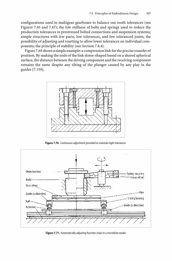
7.4 Principles of Embodiment Design 307
configurations used in multigear gearboxes to balance out tooth tolerances (seeFigures 7.45 and 7.47); the low stiffness of bolts and springs used to reduce theproduction tolerances in prestressed bolted connections and suspension systems;simple structures with few parts, low tolerances, and few toleranced joints; thepossibility of adjusting and resetting to allow lower tolerances on individual com-ponents; the principle of stability (see Section 7.4.4).
Figure 7.69 shows a simple example: a compression link for the precise transfer ofposition. By making the ends of the link dome-shaped based on a shared sphericalsurface, the distance between the driving component and the receiving componentremains the same despite any tilting of the plunger caused by any play in theguides [7.159].
Figure 7.70. Continuous adjustment provided to maintain tight tolerances
Figure 7.71. Automatically adjusting function chain in a microfiche reader
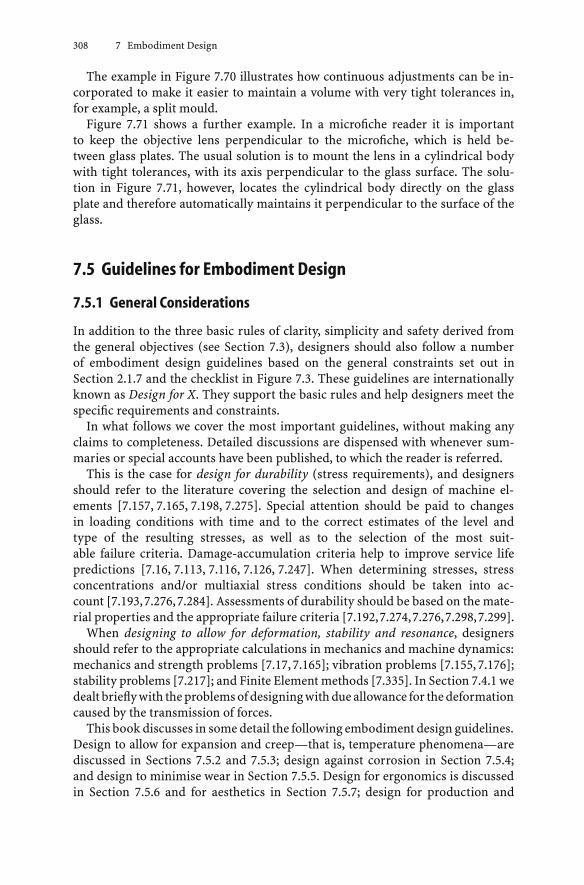
308 7 Embodiment Design
The example in Figure 7.70 illustrates how continuous adjustments can be in-corporated to make it easier to maintain a volume with very tight tolerances in,for example, a split mould.
Figure 7.71 shows a further example. In a microfiche reader it is importantto keep the objective lens perpendicular to the microfiche, which is held be-tween glass plates. The usual solution is to mount the lens in a cylindrical bodywith tight tolerances, with its axis perpendicular to the glass surface. The solu-tion in Figure 7.71, however, locates the cylindrical body directly on the glassplate and therefore automatically maintains it perpendicular to the surface of theglass.
7.5 Guidelines for Embodiment Design
7.5.1 General Considerations
In addition to the three basic rules of clarity, simplicity and safety derived fromthe general objectives (see Section 7.3), designers should also follow a numberof embodiment design guidelines based on the general constraints set out inSection 2.1.7 and the checklist in Figure 7.3. These guidelines are internationallyknown as Design for X. They support the basic rules and help designers meet thespecific requirements and constraints.
In what follows we cover the most important guidelines, without making anyclaims to completeness. Detailed discussions are dispensed with whenever sum-maries or special accounts have been published, to which the reader is referred.
This is the case for design for durability (stress requirements), and designersshould refer to the literature covering the selection and design of machine el-ements [7.157, 7.165, 7.198, 7.275]. Special attention should be paid to changesin loading conditions with time and to the correct estimates of the level andtype of the resulting stresses, as well as to the selection of the most suit-able failure criteria. Damage-accumulation criteria help to improve service lifepredictions [7.16, 7.113, 7.116, 7.126, 7.247]. When determining stresses, stressconcentrations and/or multiaxial stress conditions should be taken into ac-count [7.193,7.276,7.284]. Assessments of durability should be based on the mate-rial properties and the appropriate failure criteria [7.192,7.274,7.276,7.298,7.299].
When designing to allow for deformation, stability and resonance, designersshould refer to the appropriate calculations in mechanics and machine dynamics:mechanics and strength problems [7.17, 7.165]; vibration problems [7.155, 7.176];stability problems [7.217]; and Finite Element methods [7.335]. In Section 7.4.1 wedealt briefly with the problems of designing with due allowance for the deformationcaused by the transmission of forces.
This book discusses in some detail the following embodiment design guidelines.Design to allow for expansion and creep—that is, temperature phenomena—arediscussed in Sections 7.5.2 and 7.5.3; design against corrosion in Section 7.5.4;and design to minimise wear in Section 7.5.5. Design for ergonomics is discussedin Section 7.5.6 and for aesthetics in Section 7.5.7; design for production and

7.5 Guidelines for Embodiment Design 309
assembly, including quality control and transport, is dealt with at some length inSections 7.5.8 and 7.5.9; and design for maintenance in Section 7.5.10. Design forrecycling is discussed in Section 7.5.11; design for minimum risk in Section 7.5.12;and design to standards in Section 7.5.13.
7.5.2 Design to Allow for Expansion
Materials used in technical systems tend to expand when they are heated. Theresulting problems must be taken into consideration, not only in the design ofthermal devices in which higher temperatures must be expected as a matter ofcourse, but also in high-performance engines and devices in which frictionalheating can occur and special cooling is employed. As a result, several areas willbe affected by local heating. Moreover, devices whose environmental temperaturefluctuates significantly will only work properly if the physical effects of thermalexpansion have been allowed for in the design [7.202, 7.206].
Apart from the thermal effects of linear expansion, designers must also considerthe purely mechanical extension of parts subjected to heavy loading. In principle,the guidelines also apply to this type of change of length.
1. Expansion
Expansion has been the subject of a host of special studies. For solid bodies, thecoefficient of linear expansion is defined as:
α = ∆l/(l · ∆ϑm)
where ∆l = change in length (expansion) due to a temperature rise of ∆ϑm, l =the length of the component under consideration, and ∆ϑm = mean temperaturedifference to which the body is subjected.
The coefficient of linear expansion defines the expansion of a solid along onecoordinate axis only, while the coefficient of cubical expansion defines the relativechange in volume per degree of temperature rise. For homogeneous solids, itsvalue is three times that of the coefficient of linear expansion. Coefficients ofexpansion should be understood as mean values over a particular temperaturerange; they depend not only on the material but also on the temperature. At highertemperatures, the coefficient usually increases.
Figure 7.72 gives the coefficients of linear expansion for distinct groups ofengineering materials. It shows that with commonly used combinations of metals,for example 35C carbon steel with austenitic (10C/18% Cr-Ni-Nb) steel, or greycast iron with bronze or aluminium, great care must be taken to allow for relativeexpansions because of the significant differences in the coefficients of thermalexpansion between the materials. With large dimensions, even relatively smalldifferences between, say, 35C carbon steel and 13% chromium steel (10C/13% Cr)can cause serious problems.
Metalswitha lowmeltingpoint, suchasaluminiumandmagnesium,havegreatercoefficients of thermal expansion than metals with a high melting point, such as

310 7 Embodiment Design
Figure 7.72. Mean coefficients of linear expansion for various materials: a metallic; b synthetic
tungsten, molybdenum and chromium. Nickel alloys have different coefficientsdepending on their nickel content. Very low values occur in the range of 32–40%by weight, with 36% Ni-64% Fe, known as “Invar”, having the lowest coefficient.Synthetic materials have significantly higher coefficients of expansion than metals.
2. Expansion of Components
To calculate changes in length ∆l, designers must know the temperature distri-bution (position and time) in the component and hence the mean temperaturechange with respect to the initial value. If the temperature distribution does not

7.5 Guidelines for Embodiment Design 311
change with time, we speak of a steady or fixed expansion. If the temperaturedistribution changes with time, we speak of an unsteady or fluctuating expansion.
In thecaseof steadyexpansion, thephysicalquantitiesuponwhich theexpansionof a component depends is obtained from the basic equations:
∆l = α · l · ∆ϑm ∆ϑm =1l
∫ l
0∆ϑ(x)dx
The change in length ∆l is therefore dependent on:
• the coefficient of linear expansion α
• the length l of the component
• the mean temperature change ∆ϑm over this length.
The value thus determined has a direct bearing on the design: every componentmust be clearly located and must only have as many degrees of freedom as arenecessary for its proper functioning. In general, a point is fixed and the requisitetranslational and rotational movements are set by appropriate guides, for exampleslides, bearings, etc. A body in space (a satellite or helicopter) has three transla-tional degrees of freedom in the x, y and z directions and three rotational degreesof freedom about the x, y and z axes. A sliding pivot (for example the nonlocatingbearing of a shaft) provides two degrees of freedom: one translational and one ro-tational. A body clamped at one point (for example a built-in beam), on the otherhand, has no degrees of freedom. Layouts based on these considerations alone donot, however, allow for expansion automatically, as we shall now demonstrate.
Figure 7.73a shows a body clamped at one point with no degrees of freedom.Upon thermal expansion it can expand freely from this point along the variousaxes. Figure 7.73b shows a plate that can be rotated about the z axis and thus hasone degree of freedom. As shown in Figure 7.73c, this single degree of freedom canbe simply removed by means of a slide. Were this plate to expand under uniformtemperature increases, it would have to rotate about the z axis, for the slide doesnot lie in the direction of the expansion that results from the change of length inthe x and y directions. If the slide allowed only translational movement and did notalso act as a pivot, then jamming would occur. By fitting the slide in the directionof one of the coordinates (see Figure 7.73d), it is possible to avoid the rotation ofthe component.
After deformation due to thermal expansion, geometric similarity will only bemaintained if the following conditions are met:
• The coefficient of expansion α must be constant throughout the component(isotropy), which can be taken for granted in practice provided that onlyone kind of material is used and that the temperature differences are not toogreat.
• The thermal strains ε along the x, y, z axes must be such that:
εx = εy = εz = α · ∆ϑm [7.196] .
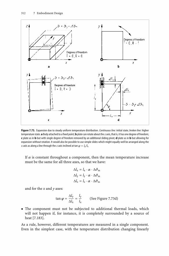
312 7 Embodiment Design
Figure 7.73. Expansion due to steady uniform temperature distribution. Continuous line: initial state; broken line: highertemperature state. aBody attached to a fixed point; b plate can rotate about the z axis, that is, it has one degree of freedom;c plate as in b but with single degree of freedom removed by an additional sliding pivot; d plate as in b but allowing forexpansion without rotation. It would also be possible to use simple slides which might equally well be arranged along thex axis as along a line through the z axis inclined at tan ϕ = ly/lx
If α is constant throughout a component, then the mean temperature increasemust be the same for all three axes, so that we have:
∆lx = lx · α · ∆ϑm
∆ly = ly · α · ∆ϑm
∆lz = lz · α · ∆ϑm
and for the x and y axes:
tan ϕ =∆ly∆lx
=lylx
(See Figure 7.73d)
• The component must not be subjected to additional thermal loads, whichwill not happen if, for instance, it is completely surrounded by a source ofheat [7.183].
As a rule, however, different temperatures are measured in a single component.Even in the simplest case, with the temperature distribution changing linearly

7.5 Guidelines for Embodiment Design 313
along the x axis (see Figure 7.74a), a change in angle is produced which, again,can only be taken up by a guide with a sliding as well as a pivoting movement.A simple slide, which allows translational movement with one degree of freedom,can only be used if the guide lies along the line of symmetry of the deformation(see Figure 7.74b). If this condition is not fulfilled, a further degree of freedommust be allowed.
Hence we obtain the rule that guides that take up thermal expansion and haveone degree of freedom must only lie on a line through the fixed point, and this linemust be the line of symmetry of the deformed state. The deformed state can becaused by load-dependent and temperature-dependent stresses, in addition to theexpansion itself.
Since the stress and temperature distribution also depend on the shape of thecomponent, the required symmetry line of the deformed state should, in the firstinstance, be sought both along the symmetry line of the component and also alongthat of the superimposed temperature field. However, as Figure 7.74b shows, thisline of symmetry may not be easily identifiable from the component shape and thetemperature distribution, so that the ultimate state of deformation must also betaken into account. That state, as we said earlier, may also be caused by externalloads. To that extent, our remarks also apply to guides for components subject tolarge mechanical deformations. An example can be found in [7.8].
The following examples serve as further illustrations. Figure 7.75 is the planview of a device whose temperature decreases from the centre to the periphery. Itis supported on four feet. In Figure 7.75a, one of the feet is chosen as the fixed point.If the device is not to rotate or jam, the guide may only be placed along the line ofsymmetry of the temperature field, that is, on the opposite foot. Figure 7.75b showsa method of providing guides along lines of symmetry without a designated fixedpoint. The intersection of the lines through the guides constitutes an imaginaryfixed point from which the device can expand evenly in all directions. In that case,two guides, for example 1 and 2, could be omitted.
Figure 7.76 shows the location of inner casings in outer casings when a commoncentre must be maintained, as occurs, for instance, in turbines. If the deformed
Figure 7.74. Expansion under nonuniform temperature distribution, here decreasing linearly along the x axis: a platecorresponding to Figure 7.73d, nonuniform temperature distribution produces deformation shown by broken line, slidingpivot required; b guide placed on symmetry line of deformed state so that a simple slide can be used

314 7 Embodiment Design
Figure 7.75. Plan view of a device mounted on four feet, whose temperature decreases from the centre to the periphery:a designated fixed point on one foot; simple slide along a line that is also the symmetry line of the temperature field;b imaginary fixed point in the centre of the device formed by the intersection of the lines of expansion
Figure 7.76. Location of inner casings in outer casings: a arrangement of guides does not allow for expansion: ovaldeformation of the housings can cause guides to jam; b arrangement allowing for expansion: guides lie along symmetrylines, no jamming with oval deformation
shape of these components is not completely rotationally symmetrical, then theguides must be placed on the lines of symmetry to prevent jamming of the guidesdue to, say, oval deformation of the casings (see Figure 7.76b). Such oval deforma-tion is caused by temperature differences in the housing wall and flange, especiallyduring the warm-up phase. The imaginary fixed point lies on the longitudinal axisof the casing or shaft.
Figure 7.77 shows an austenitic steel high-temperature steam inlet pipe a whichmust be fitted into a ferritic steel outer casing b while protruding into a ferritic steelinner casing c. Because of marked differences in the two coefficients of expansionand also because of the considerable temperature differences between the compo-nents, particular attention must be paid to relative expansion. An imaginary fixed
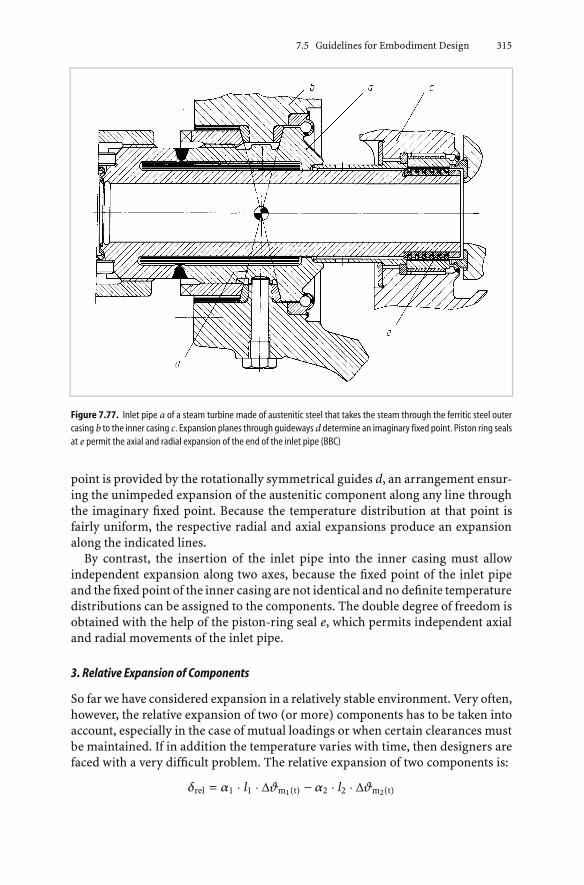
7.5 Guidelines for Embodiment Design 315
Figure 7.77. Inlet pipe a of a steam turbine made of austenitic steel that takes the steam through the ferritic steel outercasing b to the inner casing c. Expansion planes through guideways d determine an imaginary fixed point. Piston ring sealsat e permit the axial and radial expansion of the end of the inlet pipe (BBC)
point is provided by the rotationally symmetrical guides d, an arrangement ensur-ing the unimpeded expansion of the austenitic component along any line throughthe imaginary fixed point. Because the temperature distribution at that point isfairly uniform, the respective radial and axial expansions produce an expansionalong the indicated lines.
By contrast, the insertion of the inlet pipe into the inner casing must allowindependent expansion along two axes, because the fixed point of the inlet pipeand the fixed point of the inner casing are not identical and no definite temperaturedistributions can be assigned to the components. The double degree of freedom isobtained with the help of the piston-ring seal e, which permits independent axialand radial movements of the inlet pipe.
3. Relative Expansion of Components
So far we have considered expansion in a relatively stable environment. Very often,however, the relative expansion of two (or more) components has to be taken intoaccount, especially in the case of mutual loadings or when certain clearances mustbe maintained. If in addition the temperature varies with time, then designers arefaced with a very difficult problem. The relative expansion of two components is:
δrel = α1 · l1 · ∆ϑm1(t) − α2 · l2 · ∆ϑm2(t)

316 7 Embodiment Design
Steady-State Relative Expansion
If the relative mean temperature difference does not vary with time, and if the co-efficients of linear expansion are identical, then all that has to be done to minimisethe relative expansion is to even out the temperature or else to select materialswith different coefficients of expansion. Often both are necessary.
This can be seen in the case of a flanged connection consisting of a steel stud andan aluminium flange [7.200]. Because the aluminium has a higher coefficient ofexpansion, a temperature rise will increase the load on the stud, which may lead tofailure (see Figure 7.78a). This can be prevented, on the one hand, by increasing thelength of the stud and using a sleeve and, on the other hand, by using componentswith appropriate coefficients of expansion (see Figure 7.78b). If relative expansionis to be avoided altogether, then we must have:
δrel = 0 = α1 · l1 · ∆ϑm1 − α2 · l2 · ∆ϑm2 − α3 · l3 · ∆ϑm3
With l1 = l2 + l3 and λ = l2/l3, the relative length of sleeve to flange becomes:
λ =α3 · ∆ϑm3 − α1 · ∆ϑm1
α1 · ∆ϑm1 − α2 · ∆ϑm2
With steady-state expansion, ∆ϑm1 = ∆ϑm2 = ∆ϑm3, and with steel (αl =11 × 10−6), Invar (α2 = 1 × 10⁻⁶) and aluminium alloy (α3 = 20 × 10−6) as thechosen materials (see Figure 7.78b), we have λ = l2/l3 = 0.9.
Designers will be familiar with the complicated expansion problems asso-ciated with the pistons of internal combustion engines. Here, the tempera-ture distribution over and along the piston differs even in the near-steady
Figure 7.78. Connection by means of a steel stud and aluminium flange [7.200]: a stud endangered because aluminiumflange has greater expansion; b incorporation of Invar expansion sleeve with a coefficient of expansion close to zero helpsto balance the relative expansion of flange and stud

7.5 Guidelines for Embodiment Design 317
state and, what is more, differences in the coefficients of expansion of pistonand cylinder must also be taken into account. One solution is the use of analuminium–silicon alloy with a relatively small coefficient of expansion (smallerthan 20 × 10−6); of expansion-inhibiting inserts that are also good heat con-ductors; and of a flexible piston skirt. The bimetallic effect provided by steelinserts also helps to match the shape of the piston skirt to that of the cylin-der [7.178] (see Figure 7.79). A further possibility is to make the piston oval-shaped.
If, on the other hand, the choice of materials is restricted in practice, thendesigners must rely on temperature adjustments. In high-power generators, forinstance, large lengths of insulated copper rod must be embedded in the steelrotors. For insulation purposes alone, the absolute and relative expansions mustbe kept as small as possible. Here the only solution is to keep the temperature toa minimum by cooling [7.163, 7.317]. However, if these fast-running rotors havelarge dimensions, thermal imbalances may occur even though the temperaturedistribution is relatively uniform. The rotor, because of its complicated structureand the various materials that have gone into it, may not always (and at every point)display the same temperature-dependent behaviour. This can only be remediedif the expansions are kept under control by the carefully planned introduction ofappropriate cooling or heating.
Figure 7.79. Piston of internal combustion engine made of aluminium–silicon alloy with steel inserts which inhibitcircumferential expansion; moreover the bimetallic effect ensures optimum adaptation of the piston skirt to the cylinder(Mahle), after [7.178]
Unsteady Relative Expansion
If the temperature changes with time, for instance during heating or coolingprocesses, we often obtain a relative expansion that is much greater than thatfound in the final steady state. This is because the temperatures of the individualcomponents can differ considerably. In the common case, where the components
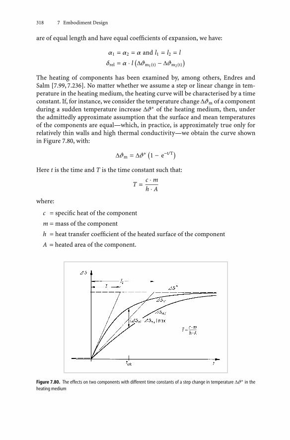
318 7 Embodiment Design
are of equal length and have equal coefficients of expansion, we have:
α1 = α2 = α and l1 = l2 = l
δrel = α · l(∆ϑm1(t) − ∆ϑm2(t)
)The heating of components has been examined by, among others, Endres andSalm [7.99, 7.236]. No matter whether we assume a step or linear change in tem-perature in the heating medium, the heating curve will be characterised by a timeconstant. If, for instance, we consider the temperature change ∆ϑm of a componentduring a sudden temperature increase ∆ϑ∗ of the heating medium, then, underthe admittedly approximate assumption that the surface and mean temperaturesof the components are equal—which, in practice, is approximately true only forrelatively thin walls and high thermal conductivity—we obtain the curve shownin Figure 7.80, with:
∆ϑm = ∆ϑ∗ (1 − e−t/T)
Here t is the time and T is the time constant such that:
T =c · mh · A
where:
c = specific heat of the component
m = mass of the component
h = heat transfer coefficient of the heated surface of the component
A = heated area of the component.
Figure 7.80. The effects on two components with different time constants of a step change in temperature ∆ϑ∗ in theheating medium

7.5 Guidelines for Embodiment Design 319
Despite the simplification involved, this approach may be considered to be fun-damental. With two components that have different time constants, we obtaintemperature curves that, at a given critical time, will have a maximum difference.At this point we have maximum relative expansion, and must provide clearancesto accept the expansion or run the risk of excessive stresses beyond the yield point.Two identical temperature curves appear if the time constants of the two compo-nents can be equalised. In that case, there is no relative expansion. This objectivecannot always be achieved, but in order to render the time constants approximatelyequal—that is, to reduce the relative expansion—the following relationship:
T = c · ρ · VA
· 1h
where V = volume of the component and ρ = density of the component, can beused by designers to:
• adapt the ratio of the volume V to the heated surface area A, or
• adjust the heat transfer coefficient h by means of, say, lagging or selectingdifferent cooling airflow rates.
Figure 7.81 gives the relationship V/A for a number of simple but representativebodies.
Figure 7.81. Volume–surface area relationships for various geometrical bodies; arrows point to heated surfaces
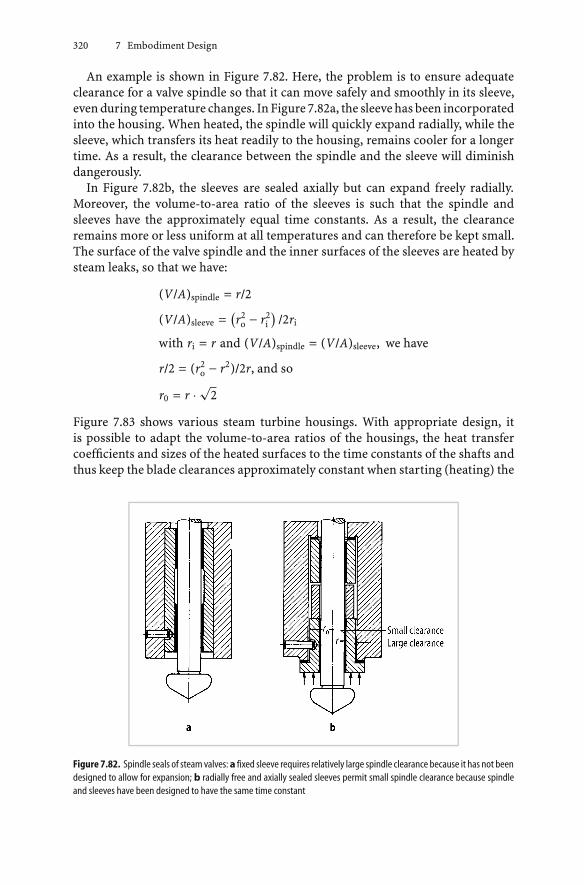
320 7 Embodiment Design
An example is shown in Figure 7.82. Here, the problem is to ensure adequateclearance for a valve spindle so that it can move safely and smoothly in its sleeve,even during temperature changes. In Figure 7.82a, the sleeve has been incorporatedinto the housing. When heated, the spindle will quickly expand radially, while thesleeve, which transfers its heat readily to the housing, remains cooler for a longertime. As a result, the clearance between the spindle and the sleeve will diminishdangerously.
In Figure 7.82b, the sleeves are sealed axially but can expand freely radially.Moreover, the volume-to-area ratio of the sleeves is such that the spindle andsleeves have the approximately equal time constants. As a result, the clearanceremains more or less uniform at all temperatures and can therefore be kept small.The surface of the valve spindle and the inner surfaces of the sleeves are heated bysteam leaks, so that we have:
(V/A)spindle = r/2
(V/A)sleeve =(r2o − r2
i
)/2ri
with ri = r and (V/A)spindle = (V/A)sleeve, we have
r/2 = (r2o − r2)/2r, and so
r0 = r · √2
Figure 7.83 shows various steam turbine housings. With appropriate design, itis possible to adapt the volume-to-area ratios of the housings, the heat transfercoefficients and sizes of the heated surfaces to the time constants of the shafts andthus keep the blade clearances approximately constant when starting (heating) the
Figure 7.82. Spindle seals of steam valves: a fixed sleeve requires relatively large spindle clearance because it has not beendesigned to allow for expansion; b radially free and axially sealed sleeves permit small spindle clearance because spindleand sleeves have been designed to have the same time constant

7.5 Guidelines for Embodiment Design 321
Figure 7.83. Steam turbine housings with different time constants
turbines. Another approach is to ensure that the relative expansion is such that theclearance increases rather than decreases during start-up.
There are several well-known methods for reducing the heat transfer coefficientof a component (for example by insulation), and thus for slowing down the heatingand reducing the relative expansion.
The ideas we have just put forward are applicable wherever temperatures changewith time, and particularly wherever relative expansion goes hand-in-hand withclearance reductions that are likely to endanger the functioning of turbines, pistonengines and machines operating in hot environments.
7.5.3 Design to Allow for Creep and Relaxation
1. Behaviour of Materials Subject to Temperature Changes
When designing components subject to temperature changes, we must take intoaccount not only the expansion effect but also the creep properties of the materials.The temperatures involved need not necessarily be very high, although they usuallyare. However, there are some materials that will, even at temperatures well below100◦C, behave in much the same way as metals do at very high temperatures.
Beelich [7.4] has examined this subject at some length, and in what follows weshall base ourselves largely on his findings.
Materials in common use, pure metals as well as alloys, have a polycrystallinestructure and a temperature-dependent behaviour. Below a critical temperature,the stability of the intercrystalline bonds is largely independent of time, and theyield point can be used to determine the strengths of components. Components attemperatures above the critical temperature are strongly influenced by the time-dependent behaviour of the material. In this temperature range, materials will,under the influence of load, temperature and time, experience a gradual plasticdeformation that, after a given period, may lead to fracture. The ensuing time-dependent fracture stress is much lower than the 0.2% proof stress at the same

322 7 Embodiment Design
temperature determined by short-term experiments (see Figure 7.84). Criticaltemperature and creep strength depend largely on the materials used and bothmust be taken into consideration. With steels, the critical temperature lies between300◦C and 400◦C.
Figure7.84. Characteristic valuesdeterminedbyhigh-temperature tensile strength and creepexperimentswith 21C/1.5%Cr-Mo-V steel at various temperatures; the critical temperature is the intersection of the curves of 0.2% proof stress andstress for 0.2% creep strain in 105 hours
Figure 7.85. Relationship of modulus of elasticity to temperature for various materials: a metals, b synthetic materials

7.5 Guidelines for Embodiment Design 323
When working with synthetic materials, designers must allow for their vis-coelastic behaviour, even at temperatures below 100◦C.
In general, the modulus of elasticity changes inversely with the temperature (seeFigure 7.85a). The smallest changes occur with nickel alloys. As the modulus ofelasticity drops, so does the stiffness of the components—synthetic componentsin particular (see Figure 7.85b). In this case, designers must know the temperatureat which the modulus of elasticity suddenly drops to relatively low values.
2. Creep
Components that are put under loads for long periods at high temperatures will,in addition to the strain given by Hooke’s Law (ε = σ/E), also experience plasticdeformation (εplast) with time. This property of materials, which is known as creep,depends on stress, the effective temperature ϑ and time.
We say a material creeps if the strain of a component increases under constantload or stress [7.4]. The creep curves of various materials are well known [7.110,7.136].
Creep at Room Temperature
Beforewecandesigncomponents loaded tonear theyield stress,wemustknowhowthey react in the transition region between the elastic and the plastic states [7.136].With persistent static loads in this transition region, we can expect primary creepin metals even at room temperature (see Figure 7.86). The resulting plastic de-formations are small and merely affect the dimensional stability of a particularcomponent. In general, steels show little creep when subject to stress ≤ 0.75 · σ0.2
or ≤ 0.55 · σF, whereas, in the case of synthetic materials, a reliable assessment ofthe mechanical behaviour can only be made by considering the temperature andtime-dependent characteristics.
Creep Below the Critical Temperature
Previous studies [7.136, 7.147] of metals have shown that the customary calcu-lations, based on high-temperature yield strength as the maximum permissiblestress for short-term loads, additional thermal loads and load variations, sufficeup to the critical temperature.
With components that must have high dimensional stability, however, the char-acteristics of the material determined by creep experiments must also be taken intoaccount, even at moderately high temperatures. Unalloyed and low-alloy boiler-making steels and even austenitic steels show varying degrees of creep dependingon length of operation and working temperature.
Synthetic materials experience structural changes, even at slightly elevated tem-peratures. These transformations may lead to a marked temperature and timedependence of the properties of the materials, which is not the case with met-als. In specific cases these changes are irreversible and referred to as thermalageing [7.156, 7.185].

324 7 Embodiment Design
Figure7.86. Straina and creep rate bwith duration of load (schematic representation); characteristics of the various creepphases
Creep Above the Critical Temperature
In this temperature region, mechanical loads will cause deformations in metals atfarbelowtheappropriatehigh-temperatureyield strength, that is, thematerialswillcreep. This creep leads to gradual deformation of components and can lead to lossof function and possible failure. In general, this process can be divided into threephases [7.136, 7.147] (see Figure 7.86). For components affected by temperaturechanges, the beginning of the tertiary creep phase must be considered dangerous.This region begins at approximately 1% permanent strain. Figure 7.87 shows the105-hour creep strengths σ1%/105 at 500◦C for various steels.
3. Relaxation
In loaded systems (springs, bolts, tension wires, shrink fits), the necessary preloadproduces an overall strain ε (elongation ∆l). Because of creep and settling of thematerial due to plastic flow at the bearing surfaces and split lines, the ratio of

7.5 Guidelines for Embodiment Design 325
Figure 7.87. Stresses corresponding to a 1% permanent strain for various steels after 105 hours at 500◦C [7.213]
plastic to elastic deformation gradually increases. The phenomenon of decreasingelastic strain at constant overall strain is called relaxation [7.100, 7.326, 7.327].
Loaded components are usually preloaded at room temperature. Because themodulus of elasticity varies with the temperature (see Figure 7.85), the preloaddecreases at higher temperatures, even without a change in length of the loadedsystem.
The preload remaining at operational conditions, though reduced, will lead tocreep at high temperatures and hence to a further drop in the preload (relax-ation). The residual clamping force is also affected by production and operationdetermined factors; for instance by the assembly preload, the design of the loadedsystem, the nature of the contact surfaces, and the influence of superimposedstresses (normal or tangential to the surface). Studies of the relaxation of boltedflanges [7.100, 7.326, 7.327] have shown that plastic deformation also occurs atthe split lines and bearing surfaces (settlement) and in the threads (creep andsettlement).
To sum up, we can say that, with metallic components:
• The drop in preload depends on the relative stiffness of the parts loaded againsteach other. The more rigid the connection, the greater the drop in the preloaddue to plastic deformation (creep and settlement).
• Although settlement can be appreciably offset during the tightening of boltedflangesor theassemblingof shrinkfits,designers should,wherepossible, providefor few but accurately machined surfaces (split lines, bearing surfaces).
• There is a temperature limit beyond which the material cannot be properlyused. In addition, designers should always choose materials in which the ap-

326 7 Embodiment Design
propriate high-temperature yield point is not reached, even with superimposedoperational stresses.
• In the short term, high initial preloads (initial clamping forces) give rise tohigher residual clamping forces. In the longer term, the residual clamping forcesbecome relatively independent of the initial preload.
• Joints that have already undergone relaxation can be tightened up if the tough-ness of the material permits. As a rule, creep of about 1%, which leads to thetertiary creep region, must not be exceeded.
• If joints are subjected to an alternating load in addition to the static preload,then, as experiments have shown, the amplitudes tolerated during relaxation-dependent decreases in the mean stress are considerably greater than thosetolerated at constant mean stress. However, relaxation-dependent decreases inthe mean stress will often lead to a loosening of the joint.
When using bolted joints made of synthetic materials, designers try to take advan-tage of their low electrical and thermal conductivity, their resistance to corrosion,their high mechanical damping, their small specific weight, etc. In addition, suchjoints must, of course, have the appropriate strength and toughness. Special atten-tion must also be paid to preload decay, otherwise the functioning of the joints canbe seriously impaired. Special studies [7.190, 7.191] have shown that in synthetic(unlike in metallic) materials:
• The preload remaining after a given time and at room temperature is determinedby the material itself and its tendency to absorb moisture.
• Continual changes in the absorption and release of moisture have a particularlydeleterious effect.
4. Design Features
In order to increase the potential life of components subject to long-term loads,designers must familiarise themselves with the behaviour of the materials involvedover time. According to [7.136], it is dangerous to use short-term values to predictload responses for periods of 105 hours or longer.
It is impossible to avoid thermal stresses in all components by specifying theuse of highly alloyed materials. Appropriate design features are often more usefulthan changing the materials.
The design must enable creep to be kept within permissible limits, which canbe done by means of:
• a high elastic strain reserve, which helps to minimise additional loads due totemperature fluctuations (see Figure 7.88)
• insulation or cooling of components, as in double-casing steam turbines andgas turbines (see Figure 7.89)
• the avoidance of mass concentrations which, in unsteady processes, may lead toincreased thermal loading

7.5 Guidelines for Embodiment Design 327
• the prevention of creep in unwanted directions, which can cause functionalfailure (for instance the jamming of valve spindles) or dismantling problems(see Figure 7.90).
Figure 7.88. Austenitic–ferritic steel flanged joint intended for operating temperatures of 600◦C [7.265]
Figure 7.89. Double-casing steam turbine with shrink rings that hold the inner casing together. Relaxation of the shrinkrings is reduced by cooling with exhaust steam. As the machine increases its output, the shrink rings exert an increasingpressure thanks to growing temperature difference between the steam inlet and outlet. The shrink rings are seated onheat-inhibiting segments which, with the help of shims, permit the original shrink fit to be restored after relaxation (ABB)

328 7 Embodiment Design
Figure 7.90. Centering and sealing of a cover [7.206]. a Dismantling is impeded because the material creeps into the reliefgroove and aty;b convex sealing edge provides a better sealwith smaller sealing force. Creep does not impede dismantlingthanks to improved design
In Figure 7.90a, the material of the cover creeps into the relief groove. The cover,which heats up more quickly, presses against the centering surface and also creepsat point y. The cover shown in Figure 7.90b is a better design since, despite thecreep, it can be dismantled easily. In addition, the cover has been made hollowso that it cannot exert a significant radial force on the centering surface. In otherwords, the part which is moved during dismantling should not project axiallybeyond the fixed part [7.206].
7.5.4 Design Against Corrosion
It often happens that corrosion can only be reduced, not completely avoided.Rubo [7.235] emphasises the use of components with the same corrosion resis-tance in a machine. The use of corrosion-proof materials throughout may not beeconomic, in which case suitable embodiments can be used to retain functionalitydespite corrosion. This suggests a shift from focusing on corrosion protection todesigning machines and their components to be corrosion tolerant. It follows thatdesigners must tackle corrosion with appropriate concepts or special embodimentdesign features. The measures they take will depend on the type of corrosion antic-ipated. An extensive description of the types of corrosion and many useful designfeatures are provided in the guidelines on design against corrosion in [7.158].Spähn, Rubo and Pahl [7.212, 7.261] describe various types of corrosion and theirremedies, and the following remarks are largely based on their findings. In orderto provide a systematic categorisation from a design viewpoint, these are set outslightly differently from DIN 50900 [7.80, 7.81].
1. Causes and Effects of Corrosion
While the formation of metal oxide layers in dry environments and at highertemperatures tends to increase chemical resistance to corrosion, relatively weakelectrolytes are formed in conditions below the dew point, and these generallylead to electrochemical corrosion [7.260]. Corrosion is also fostered by the factthat different components have contacting surfaces with different properties, for

7.5 Guidelines for Embodiment Design 329
instance due to the inclusion of various noble or base metals, to differences in crys-talline structure, and to residual stresses set up, for instance, by heat treatment andwelding. In addition, wherever the design calls for slits or holes, local differences inelectrolyte concentration appear, even in the absence of clear differences in electricpotential, due to the use of different materials.
Figure 7.91. Types of corrosion

330 7 Embodiment Design
According to [7.80, 7.212] (see Figure 7.91) we must distinguish between:
• free surface corrosion
• contact corrosion
• stress corrosion
• selective corrosion within the material.
The preventive measures depend on the respective causes and effects. Variousexamples are given in the following sections.
2. Free Surface Corrosion
The corrosion of free surfaces can be uniform or locally concentrated. The latter isparticularly dangerous because, in contrast to uniform corrosion, it leads to highstress concentrations and is often difficult to predict. It is, therefore, necessary topay particular attention right from the start to potential danger zones.
Uniform Corrosion
Cause:The presence of moisture (weak electrolytes) combined with oxygen from the
air or the contacting medium, particularly below the dew point.
Effects:Extensiveuniformcorrosionof the surface—insteel, for instance, approximately
0.1 mm per annum in a normal atmosphere. Sometimes more pronounced locally,especially in zones frequently kept below the dew point and hence subject to mois-ture concentration. Uniform corrosion is fostered by a more aggressive medium,higher flow velocity, and local heat transmission.
Remedies:
• Provide uniform service life by means of appropriate wall thicknesses and ma-terials.
• Select a concept that obviates corrosion or makes it economically acceptable(see Example 1 below).
• Use small and smooth surfaces involving geometrical shapes with a maximumvolume-to-surface area ratio (see Example 2 below).
• Avoid moisture traps (see Figure 7.92).
• Avoid temperatures below the dew point by good insulation and prevent hot orcold bridges (see Example 3 below).
• Avoid flow rates greater than 2 m/s.
• Avoid areas of high and differing thermal loads on heated surfaces.
• Apply a protective coating [7.82], possibly in conjunction with cathodic protec-tion.

7.5 Guidelines for Embodiment Design 331
Figure 7.92. Drainage of components susceptible to corrosion: a design of bases encouraging and impeding corrosion;b wrong and right arrangement of steel sections; c brackets made of channel section with drain-hole
Indentation Corrosion
This type of corrosion is not uniform over the surface.
Cause:There are components [7.81] with anodic and cathodic areas that cause differ-
ences in the rate of corrosion. These differences are usually caused by inhomoge-neous material, by a medium with varying concentrations, and by local influencessuch as temperature and radiation.
Remedies:
• Remove inhomogeneity and varying influences.
• Provide a protective coating. Damage to this coating, however, will cause stronglocal corrosion (see cavity corrosion).
Cavity Corrosion
Cavity corrosion is concentrated on small surfaces with relatively deep indenta-tions, with the depth being at least as great as the width. A clear distinction betweenindentation and cavity corrosion is not always possible.
Cause:Similar to indentation corrosion, but its occurrence is more localised.

332 7 Embodiment Design
Remedies:Basically the same as for indentation corrosion, although particular attention
should be paid to reduction and prevention.
Crevice Corrosion
Cause:Most often, the accumulation of acidic electrolytes (moisture, aqueous medium)
following thehydrolysisof corrosionproducts increvicesetc. In rust andacid-proofsteels, there is a breakdown of passivity due to depletion of oxygen in a crevice.Typically this type of corrosion is caused by insufficient ventilation.
Effects:Increased corrosion in hidden areas. Increased stress concentrations in areas
that are, in any case, under greater stress. Danger of fracture or separation withoutprior warning.
Remedies:
• Provide smooth, crevice-free surfaces and connections.
• Provide weld seams without permanent crevices; use butt seams or through-welded fillet seams (see Figure 7.93).
• Seal crevices, for instance by providing protruding parts with moisture-proofsleeves or coatings.
• Enlarge crevices so that throughflow prevents the accumulation of moisture.
Figure 7.93. Examples of welded joints: a susceptible to crevice corrosion; b correct design, after [7.260]; c crevice-freewelding of pipes, also improves resistance to stress corrosion cracking

7.5 Guidelines for Embodiment Design 333
3. Contact Corrosion
Bimetallic Corrosion
Cause:The contact of two metals with different potentials in the presence of an elec-
trolyte, that is, a conductive fluid or vapour [7.259].
Effects:The baser of the two metals will corrode more rapidly than the nobler round the
contact area, and this will occur more quickly for a smaller surface area (galvaniccorrosion). Once again, the stress concentration is increased and corrosion prod-ucts may be deposited. Such deposits have secondary effects of various kinds; forinstance the production of sludge, contamination of the medium, etc.
Remedies:
• Use combinations of metals with small potential differences and hence a smallcontact current.
• Prevent action of electrolytes on the contact area by providing local insulationbetween the two metals.
• Avoid electrolytes altogether.
• If necessary, resort to planned corrosion by introducing still baser materials inthe form of sacrificial anodes.
Deposit Corrosion
Cause:Unwanted materials become deposited on the surface or in crevices and cause
potential differences at particular locations. These deposits can come from ex-isting corrosion, the surrounding medium, vaporisation residues, excess sealingmaterial, etc.
Remedies:
• Avoid, filter, or collect the deposits.
• Prevent water traps, aim at smooth flow, maintain reasonable speed and self-drainage (see Figure 7.92a).
• Rinse or clean the components.
Transition Zone Corrosion
Cause:Changes in the state of the medium or its components from the liquid to the
gaseous phase and vice versa tend to increase the danger of corrosion of metallicsurfaces in the transition zone. That danger may be increased further by encrus-tations in the transition zone [7.260].

334 7 Embodiment Design
Figure 7.94. Increased corrosion at the transition from the gaseous to the liquid state, after [7.260] due to concentrationof the medium in the region of the water line of a vertically arranged condenser. This can be remedied by raising the waterlevel
Effects:This type of corrosion is concentrated in the transition zone and is more pro-
nounced with more sudden changes of state and more aggressive media [7.234].
Remedies:
• Gradually supply and remove heat using a heating or cooling element.
• Reduce turbulence, and hence heat transfer coefficients at the inlet of the affectedmedium, for instance by means of guide vanes.
• Provide corrosion-resisting jackets at critical points (see Examples 3 and 4).
• Avoid transition zone problems by appropriate design features (see Figure 7.94).
• Continuously change fluid level, for example by stirring.
4. Stress Corrosion
Components susceptible to corrosion are often mechanically loaded, either stati-cally or dynamically. The mechanical stresses produced by these loads can causeseveral serious corrosion phenomena.
Fatigue Corrosion
Cause:Corrosive attacks on a component subjected to mechanical fatigue loading ap-
preciably reduce its strength. The greater the loading, the more intense the corro-sion and the shorter the life of the component.

7.5 Guidelines for Embodiment Design 335
Effects:Fracture without distortion, as in fatigue failure. Because the corrosion prod-
ucts, especially in slightly corrosive media, can only be seen under a microscope,this type of corrosion is often mistaken for normal fatigue failure.
Remedies:
• Minimise alternating mechanical or thermal stresses and especially avoid oscil-latory stresses due to resonance phenomena.
• Avoid stress concentrations.
• Provide compressive stresses on the surface by shotblasting, roller burnishing,nitriding, etc., to increase the working life.
• Avoid contact with corrosive media (electrolytes).
• Provide surface coating (for example rubber, baked enamel, hot dip galvanisa-tion, aluminium, etc.).
Stress Corrosion
Cause:Certain sensitive materials tend to develop transcrystalline or intercrystalline
cracks if static tensile stresses are combined with a specific trigger.
Effects:Depending on the medium [7.260], various very fine and rapidly developing
transcrystalline or intercrystalline cracks appear in the component. Adjacent partsare not affected.
Remedies:
• Avoid sensitive materials, which may not, however, be possible because of otherrequirements. These materials are: unalloyed carbon steels, austenitic steels,brass, magnesium, aluminium alloys and titanium alloys.
• Substantially reduce or completly avoid tensile stresses on the attacked surfaces.
• Introduce compressive stresses on the surface, for instance by shrink fits, bypreloaded multilayer materials, or by shotblasting.
• Reduce residual tensile stresses by annealing.
• Apply cathodic coatings.
• Avoid corrosive influences by lowering the concentration and temperature.
Strain-Induced Corrosion
Cause:Under repetitive large extensions or compressions, any protective outer layer
cracks and opens repeatedly. This removes the protection and local corrosion willoccur.

336 7 Embodiment Design
Remedy:Reduce the magnitude of any extensions and compressions.
Erosion and Cavitation Corrosion
Corrosion may accompany erosion and cavitation, in which case the breakdownof the material is accelerated. The basic remedy is the avoidance or reduction oferosion and cavitation by hydrodynamic means or special design features. Onlywhen this is not possible should such hard surface treatments such as metalspraying or hard chrome coating be considered.
Abrasion Corrosion
Cause:Abrasive corrosion can be caused by relatively small movements between two
surfaces subject to contact stresses (see also Section 7.4.1). Abrasion spots canappear, for instance, as a result of thermal expansion, or of pipes vibrating againsttheir guides, etc. In either case, the oxidic protection layer on the surfaces of therubbing parts may become damaged. Exposed metallic areas have a more negativeelectrochemical potential than those covered with a protective layer. If the fluidmedium is an electrolyte, these relatively small exposed areas will be broken downelectrochemically unless the protective layer can be regenerated.
Effects:The affected surfaces form hard oxidation products (so-called abrasion rust)
that speed up the process. At the same time, stress concentrations increase.
Remedies:The most effective remedy is the removal of the abrasive movement, for example
through elastic suspensions or hydrostatic bearings.If the abrasive movement cannot be removed, the following measures should be
adopted:
• Reduce the vibration of the pipes by reducing the flow velocity inside themand/or change the distances between the guides.
• Increase the gaps between the pipes and their guides so that no rubbing contacttakes place.
• Increase the wall thicknesses of the pipes, thus increasing their stiffness and thetolerable corrosion rate.
• Use pipe materials that readily accept protective coatings.
5. Selective Corrosion within a Material
In the case of selective corrosion, only certain interfaces in the material matrix areaffected. Of importance are:

7.5 Guidelines for Embodiment Design 337
• intercrystalline corrosion of stainless steels and aluminium alloys
• so-called “spongiosis”—graphite corrosion of cast iron when iron particlesseparate out
• dezincification of brass (zinc separation).
Cause:Many material constituents or intercrystalline areas are less corrosion-resistant
than the bulk material matrix.
Remedy:Suitable selection of materials and their processing, such as adopting welding
procedures which avoid producing a corrosion-sensitive material structure. De-signers need to consult a materials expert when this type of corrosion is thoughtto be likely.
6. General Recommendations
In general, designers should aim at ensuring maximum and uniform lives for allcomponents [7.234,7.235]. If it should prove economically impossible to meet theserequirements with the appropriate choice of materials and layout, then designersmust provide for the regular monitoring of all areas and components particularlyprone to corrosion. This can done by visual inspection and regular measurementsof wall thicknesses, directly by mechanical or ultrasonic methods and/or indirectlyby means of corrosion probes that can be scrutinised and replaced at regularintervals.
Corrosion should never be allowed to proceed to the point where it threatenssafety (see Section 7.3.3).
Finally, the reader is referred back to the principle of the division of tasks (seeSection 7.4.2), with can enable even difficult corrosion problems to be solved. Thus,one component might provide protection against corrosion and provide a seal,while another provides support or transmits forces. As a result, the combinationof high mechanical stresses with corrosion stresses is avoided, and the choice ofmaterials for any one component becomes easier [7.207].
7. Examples of Design against Corrosion
Example 1
Lye is used to absorb CO2 from a gaseous mixture under pressure, and the CO2-enriched lye is then forced to surrender much of its CO2 by expansion (regenera-tion). The position of the expansion chamber in a gas-washing plant is determinedby the following factors.
If the lye were expanded immediately behind the washing tower (see Figure 7.95,point A) the pipework to B would have to withstand lower pressures and wouldtherefore permit a saving in wall thickness. However, because of the release of

338 7 Embodiment Design
Figure 7.95. Influence of the point chosen for the expansion of CO2-enriched lye on the choice ofmaterial for the pipeworkfrom A to B
CO2, the aggressiveness of the lye permeated with CO2 bubbles would increase tosuch an extent that the cheap unalloyed pipe steel commonly used would proveinadequate and hence have to be replaced with a more expensive rust- and acid-proof material. For that reason, it is far better to keep the CO2-enriched lye underpressure until it enters the regeneration tower (point B).
Example 2
In this example, designers have to choose between two methods of storing com-pressed gases (see Figure 7.96): (a) 30 cylindrical containers, each with a capacityof 50 litres and a wall thickness of 6 mm; and (b) one spherical container witha capacity of 1.5 m3 and a wall thickness of 30 mm. Solution (b) is less prone tocorrosion for two reasons:
• The surface exposed to corrosive attack is approximately 6.4 m2, which is aboutfive times smaller than that in (a). In other words, less material is lost throughcorrosion to the same depth.
Figure 7.96. Influence of container shape on corrosion [7.234] for gases stored at 200 bar: a in 30 cylinders with a capacityof 50 litres each; b in a sphere with a capacity of 1.5m3

7.5 Guidelines for Embodiment Design 339
• For an anticipated corrosion depth of 2 mm in ten years, the loss of strength in(a) is such that the walls of the containers must be increased to a thickness of8 mm, while corrosion to a depth of 2 mm in the 30 mm wall of container (b) isrelatively insignificant. The spherical container can be dimensioned by consid-ering strength requirements only and is therefore the better design of the two.
Example 3
Figure 7.97a shows a container holding a mixture of superheated steam andCO2 [7.234]. The outlet is not insulated and cooling leads to the formation ofa condensate with strong electrolytic properties. Corrosion will attack at the tran-sition zone between the condensate and the gases, with the result that the outletmay break away.
Figure 7.97b shows a solution using insulation and Figure 7.97c one usingseparate components made of more durable materials.
Figure 7.97. Outlet of a container for superheated steam and CO2 under pressure: a original design; b insulated outletavoiding condensation; c other corrosion-resistant variants with separate components
Example 4
In a heated pipe carrying moist gases, the inlet to the heated area is particularlyprone to corrosion (see Figure 7.98a). A less sudden transition (see Figure 7.98b)or an extra protective sleeve (see Figure 7.98c) offer remedies.

340 7 Embodiment Design
Figure7.98. Corrosion in aheatedpipe [7.234]:a severe corrosion at the inlet due to sudden transition;b sudden transitionavoided; c protective sleeve covers critical zone and mitigates sudden transition
7.5.5 Design to Minimise Wear
1. Causes and Effects
The causes and effects of wear are many and complex. For a deeper understandingsee the following literature: [7.28,7.121,7.153,7.258,7.314].DIN50320 [7.79]definesthe types of wear and wear mechanisms. The main consequences of wear areshorter component lives, reduced functional performance, and higher losses. Themost common and fundamental wear mechanisms affect component surfaces, inparticular at the micro level. These mechanisms are described below.
Adhesive Wear
Adhesive wear is caused by high loading between two moving surfaces, whichleads to microwelds (localised atomic binding) that are continuously broken by therelative movement between the surfaces. This results in surface damage and wearparticles.
Abrasive Wear
Abrasive wear between components is caused by hard particles in the surface ofone component (or in the medium) that micromachine (grind) the surface of theother component. This results in grooves and scoring in the direction of the relativemovement. Mild abrasive wear can lead to a smoother surface and better surfacemating; stronger wear leads to unacceptable surface damage.
Surface Disruption Wear
Surface disruption wear is caused by alternating mechanical stresses in the surfacelayers of the components. The effects are cracks, pitting, tears and wear particles.

7.5 Guidelines for Embodiment Design 341
Tribo-Chemical Wear
Tribo-chemical wear is caused by a chemical reaction between two componentsinvolving elements of the lubricant and/or the environment activated by friction(temperature increase). The effects are surface changes, such as hardened zonesor wear particles. The latter in turn again increase the wear.
2. Design Features
Designing to minimise wear involves the application of tribological measures(system: material, working geometry, surface, lubricant/fluid) or material-relatedmeasures to minimise wear between loaded components subject to relative surfacemovements.
As with other effects, such as corrosion, the first step is to try to avoid the causesof the particular wear mechanism (primary measures); for example, by applyingtribological measures to provide fluid friction between the moving surfaces andavoid dry or mixed friction. The elastohydrodynamic effect can, for example, pro-vide fluid friction for sliding movements with the appropriate conditions for fluidviscosity, sliding speed and surface loading. If the layout or operating constraintsdo not allow this approach, a hydrostatic or magnetic solution might be chosen. Inthe case of small relative movements, the use of elastic joints should be considered.
When primary measures to remove the cause are not possible, secondary mea-sures involving the materials and lubrication have to be applied to reduce the rateof wear. To reduce the wear rate, the local energy input due to the friction power perunit area, p · νR · µ, should be minimised by reducing the surface pressure (stress)p, the relative velocity νR, and/or the coefficient of friction µ. Friction coefficientsand wear coefficients for many common combinations of materials are providedin [7.28]. The wear coefficient is defined as:
Wear coefficient =Sliding displacement × Wear volume
Normal force
When wear cannot be avoided, the following measures can prove helpful:
• Filter wear particles out of the fluid flow to avoid particle build-up and increasedwear.
• Use the principle of the division of tasks (see Section 7.4.2) for structures withworking surfaces that are in danger of wear; that is, the wear zones should beeasy and economical to replace or be made out of a wear-resistant material.
• Allow the wear rate to be measured by using wear indicators and hence ensureoperational safety and timely maintenance (see 7.5.10).
7.5.6 Design for Ergonomics
Ergonomics deals with the characteristics, abilities and needs of humans and, inparticular, the interfaces between humans and technical products. A knowledge ofergonomics can lead to an embodiment that [7.173, 7.300]:

342 7 Embodiment Design
• adapts technical products to humans
• matches humans to products or activities by selection based on education andexperience.
The range of technical products also includes domestic products and those usedfor hobbies and leisure.
The emphasis of ergonomic research is moving its focus from conventionalphysical activities in production facilities to working conditions in electronicindustries and the design of user-friendly human–machine interfaces [7.56,7.311].This has, among other results, led to software tools for ergonomic workplaceassessment and design [7.164].
1. Fundamentals
The starting point is the human being, where he or she is the operator, user orrecipient. Humans can work with or be affected by technical products in many dif-ferent ways (see Section 2.1.6). In this context it is helpful to address biomechanical,physiological and psychological issues.
Biomechanical Issues
The operation and use of products requires specific body postures and movements.These result from the spatial situation resulting from the embodiment of a prod-uct (for example the position and movement of controls) combined with the bodydimensions [7.67]. This relationship can be represented and evaluated using tem-plates of body dimensions [7.70] (see Figure 7.99).
The maximum forces humans can exert are given in [7.71]. To find the acceptableforces for a particular situation, however, also requires knowledge of frequency,duration, age, gender, experience and fitness, as well as knowledge of the methodsused to calculate these influences [7.25, 7.127].
Physiological Issues
Body postures and movements resulting from the operation and use of technicalproducts involve static and dynamic muscle actions. Muscle action requires thecirculatory systemto supplyblood to themusclesbasedon theexternal loading. Forstatic muscle action (for example when supporting a load), the blood throughputis throttled and recovery of the muscle is postponed. For this reason, large loadscan only be sustained for short periods.
From an ergonomic point of view, it is important to distinguish between loads,stresses and fatigue. Loads are external influences. Loads produce stresses relatedto individual characteristics, such as age, gender, fitness, health, and training.The result of stress is fatigue, which depends on the intensity and duration of thestress. Recovery is achieved through relaxation. Fatigue-like situations, such asmonotony, however, are not recoverable through relaxation but require a changeof activity.

7.5 Guidelines for Embodiment Design 343
Figure 7.99. Application of a body template to evaluate the sitting position in a truck, after [7.70]
A further physiological requirement for human life and work is a normalbody temperature of between 36◦C and 38◦C. Despite external hot and coldsituations, and continuous heat generation within the body (increased dur-ing heavy work), the body temperature in the brain and other parts remainsnearly constant because of the heat transferred by the blood. Working re-quirements and climatic influences have to be matched through technologi-cal measures, for example ventilation or organisational changes such as workbreaks [7.68].
The senses also play an important role in work and leisure activities. Phys-iological variables involved in vision, for example, are minimum, optimum andmaximum light density and light contrasts [7.44,7.45,7.69]. The variables related tohearing are noise level and noise differences [7.306], and these must be taken intoaccount when designing acoustic warning signals in a noisy environment [7.69].The relevant signals must be based on the sensor characteristics of human beings.No clear models exist for the processing of these signals in the nervous system andthe brain. However, it is known that humans filter inputs to each of the sensorsaccording to experience, interest, etc.

344 7 Embodiment Design
Psychological Issues
Several psychological issues have to be considered in the design of technical prod-ucts. The use of sensors, for example, implies that the processing of the signalsinvolves a series of steps that can be influenced in a variety of ways. Examplesinclude optical illusions, not hearing or seeing unimportant things, and differentinterpretations. Guiding attention is therefore an important embodiment designguideline. This is true for the embodiment of control rooms [7.54], as well as forthe placing of indicators and signs on products.
Theprocessof sensing, decidingandactingusuallyproceedsundisturbed.Whenthis process, which is partially unconscious, is disturbed, conscious thinking isused to bring certainty back into the process of perceiving, deciding and acting. Inproducts where the structure and functionality cannot be seen from the outside,the cause of and remedy for unusual phenomena, such as disturbances, cannot beclarified by thinking. It is therefore necessary to convey the required informationthrough sufficient and clear signs and through operating manuals. A well-designedproduct should minimise the thinking required for its operation so that thinkingcapacity can focus on the actual task. The requirement is for an obvious config-uration; that is, one which during operation avoids thought processes that can beeasily disturbed or are susceptible to errors. For example, the relation betweenthe movement of a control and the resulting response should be obvious andsimple.
Perception and thought focus on the actual action. Learning is defined as stor-ing successful actions and knowledge for later use. For the operation and use ofproducts, for example, one has to take into account that a series of actions learntearlier may be reintroduced out of habit. Subsequent versions of a similar productshould, therefore, avoid introducing unnecessary changes in operation or use; inparticular, opposite movements or different positions for similar control actionsshould be avoided. Such changes must never be introduced if the consequences ofan error could lead to direct or indirect safety risks.
Directing and constraining human activities excessively using technical or or-ganisational systems can have a negative effect on motivation and behaviour,especially over a long period. All such activities should therefore leave space forfree actions.
2. Human Activities and Ergonomic Constraints
Humans can be involved or affected by technical processes, either actively or pas-sively. In an active relationship they can act and are deliberately involved in thetechnical product. That is, they execute certain functions such as activating, con-trolling, monitoring, loading, removing, registering, etc. In general, the followingrepetitive activities are undertaken in an activity cycle:
• Preparing for the activity, e.g. going to work.
• Gathering and processing information, e.g. observing and orienting, drawingconclusions, deciding on an action.

7.5 Guidelines for Embodiment Design 345
• Undertaking the activity, e.g. activating, connecting, separating, writing, draw-ing, talking, giving signs.
• Checking results, e.g. identifying status, checking measured values.
• Stopping the activity or starting a new one, e.g. cleaning, closing, going away,starting a new activity cycle.
Whenthe involvementofhumanbeings is functional—inotherwords,deliberate—then this involvement should be planned carefully and suitable arrangementsmade. This should start early in the design process, even when clarifying the task(see Chapter 5). It is often necessary to represent this involvement in the functionstructure (see Section 6.3).
Active Human Involvement
Whether it is sensible and useful to involve humans in technical systems has to beassessed from the viewpoints of effectiveness, efficiency and humanity (dignity andappropriateness). This initial and basic consideration influences and determines,to a large extent, the involvement of humans and thereby the solution principle.The following ergonomic aspects can be useful in the generation of solutions andas evaluation criteria [7.300] (see Table 7.4):
• Is human involvement necessary or desirable?
• Will the involvement be effective?
• Is involvement easy to achieve?
• Can the involvement be sufficiently precise and reliable?
Table 7.4. Ergonomic aspects for the requirements list and the evaluation criteria [7.300]
Active human involvement in a technical system intended to fulfil a task:
• necessary, desired• effective• simple• fast• precise• reliable• error-free• clear, sensible• learnable
Active or passive involvement through disturbing effects and side-effects on humans:
• tolerable stress• low fatigue• low annoyance• no physical danger, safe• no health risk or loss• stimulation, change, holding attention, no monotony• personal development

346 7 Embodiment Design
• Is the activity clear and sensible?
• Can the activity be learnt?
Only when the answers to these questions are positive should the involvement ofhumans in technical systems be considered.
Passive Human Involvement
Not only those actively involved, but also those passively involved will experiencedisturbing effects and side-effects from technical systems (see terminology in Sec-tion 2.1.6). The effects of energy, material and signal flows and the environment,such as vibrations [7.292], light [7.43–7.45], climate [7.68] and noise [7.306] arevery important. These effects have to be identified early on so that they can beconsidered during the selection of the working principle and the developmentof the embodiment. The following questions can be useful and can also serve asevaluation criteria (see Table 7.4):
• Are distresses tolerable, and is the emerging fatigue recoverable?
• Has monotony been avoided, and is stimulation, change and attention ensured?
• Are annoyances or disturbances few or nonexistent?
• Has physical danger been avoided?
• Has health risk or loss been excluded?
• Does the work allow for personal development?
When these questions cannot be answered satisfactorily, then another solutionshould be selected, or the existing solution considerably improved.
3. Identifying Ergonomic Requirements
In general it is not easy for designers to immediately find satisfactory answersto the questions listed above. As described in Guideline VDI 2242 [7.300], theproblem of identifying the most important influences and suitable measures canbe approached in two ways, as discussed below.
Object-Based Approach
In many cases the technical system (object) that has to be ergonomically em-bodied is known and documented, e.g. a control panel, a driver’s seat, a pieceof office equipment, or an item of protective clothing. In such cases it is use-ful to apply the checklist in Part 2 of Guideline VDI 2242 [7.301]. It is alsoimportant to be sensitive to the particular requirements of the system underconsideration and to make use of Table 7.5. Just reading the guidelines canbe very instructive and can help clarify the issues. Concrete design featurescan be based on the insights acquired or obtained from the literature listedbelow.

7.5 Guidelines for Embodiment Design 347
Table 7.5. Characteristics used to identify ergonomic requirements [7.300]
Characteristics Examples
Function Division of functions, type of functions, type of activities
Working principle Type and intensity of the physical or chemical effects, consequences such as vibration,noise, radiation, heat
Embodiment• Type Type of elements, configuration, type of operation• Form Ergonomic overall form and elements, division based on symmetry and proportion,
aesthetically pleasing• Position Configuration, arrangement, distance, direction of effect and visibility• Size Dimensions, working area, contact surfaces• Number Amount, division
Energy Adjustment force, adjustment direction, resistance, damping, pressure,temperature, moisture
Material Colour and surface finish, contact properties such as safe to touch, easy surface to hold
Signals Labelling, text, symbols
Safety Free of danger, avoiding danger sources and spots, inhibit dangerous movements,protective measures
Effect-Based Approach
In new situations—that is, when no system has been defined—it is useful to adoptthe following approach instead. The effects related to existing and thus knownenergy, material and signal flows of technical systems are identified and comparedwith the ergonomic requirements. When there are limitations, intolerable loads oreven dangers to safety, other solutions must be sought. Effects such as mechanicalforces, heat and radiation are derived from the individual types of energy and theforms in which they appear. The material flow has to be checked to identify whetherthe suggested materials are flammable, easy to ignite, poisonous, cancer-causing,etc. For this purpose, Guideline VDI 2242 Part 2 [7.301] provides a checklist ofeffects, which gives an indication of existing problems and refers to literature withpossible solutions.
The following literature are also useful:
Design of work space [7.65, 7.72, 7.127, 7.172, 7.243, 7.300]
Work physiology [7.53, 7.231]
Illumination [7.20, 7.37, 7.43–7.45, 7.55]
Computer workplace [7.52, 7.83, 7.84]
Climate [7.68, 7.246]
Operation and handling [7.24, 7.65–7.67, 7.70, 7.71, 7.78, 7.140, 7.195]
Vibration and noise [7.31, 7.306, 7.310]
Monitoring and control [7.69, 7.73, 7.74].

348 7 Embodiment Design
7.5.7 Design for Aesthetics
1. Aims
Technicalproducts shouldnotonly fulfil the required technical functionsasdefinedby the function structure (see Section 6.3) but also be aesthetically pleasing to theirusers. A considerable change has occurred recently in user expectations and in theway that products are judged.
VDI Guideline 2224 [7.296] focuses on the aesthetics of products. Starting witha technical solution, the guideline provides rules for the external form or shape;for example, it should be compact, clear, simple, unified, in line with function, andcompatible with materials and with production processes.
In many products nowadays, aesthetics are as important as technical functional-ity. This is particularly true for products aimed at large markets and used directlyby users in their daily lives. In such cases the emphasis is not only on aestheticsand use, but also on factors such as prestige, fashion and lifestyle. The forms—or better the embodiments—of consumer products are determined primarily byindustrial designers, artists and psychologists. While ensuring the technical func-tionality, they select the forms, shapes, colours and graphics—that is, the overallappearance—basedonhuman feelings andvalues. Expressionand styleplay an im-portant role; for example a military appearance may be applied to radio products,a space age look to lights, a safari image to cars, or a nostalgic feel to telephones.The body of a car, for example, is strongly based on artistic and psychological crite-ria and not only on technical criteria such as low air resistance and transportationefficiency.
It is clear that all of the requirements regarding function, safety, use andeconomyhave to be fulfilled. The aim of designers, however, is to create products that appealto customers. Given this aim, industrial design lies between engineering and art,and has to address ergonomic and visual issues in the same way as engineeringdesign has to address function and safety issues. In addition, the company imagehas to be promoted in order to underline the individuality of its products. Suchcomplex requirements suggest that the involvement of industrial designers shouldnot be left until the end of the design process. They should be part of the designteam and involved from the beginning of the task clarification phase. In specialcircumstances they can even help formulate the task or undertake preliminarydesign studies.
The result of this approach is a design process that proceeds from “outside toinside”. Continuous collaboration between industrial designers and engineeringdesigners is required to ensure that the requirements of appearance, expressionand impression still allow the technical functions to be fulfilled within the formsand shapes created.
In this collaboration, engineering designers should not try to replace industrialdesigners, but should focus on developing the technical and economic aspects ofthe product. In the same way that technical solutions are developed, visual variantshave to be proposed and evaluated, and models and prototypes made to decideon the final appearance of the product. When searching for solutions, the same
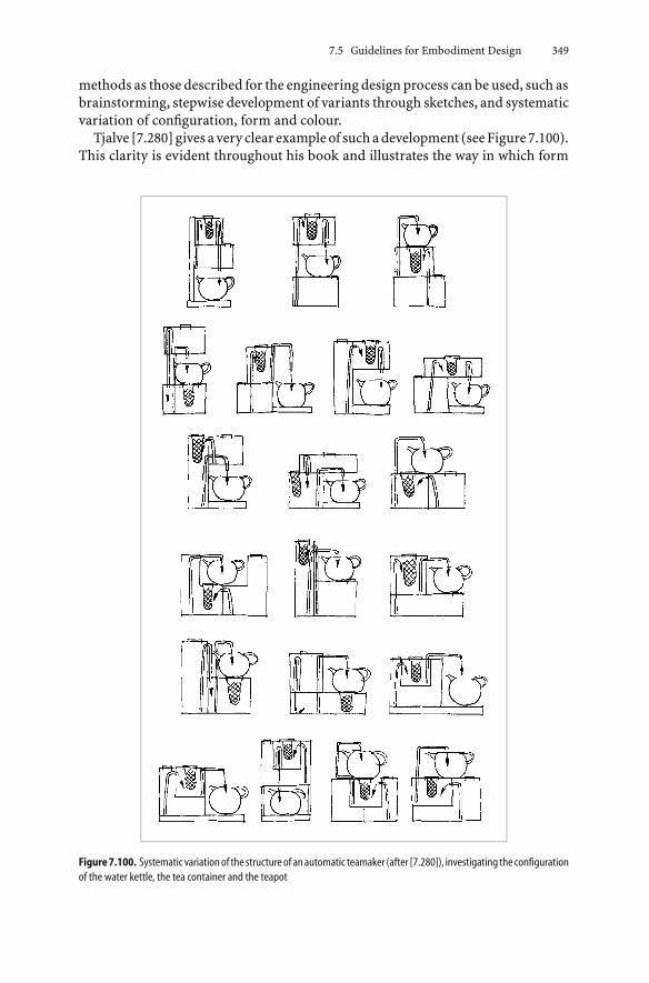
7.5 Guidelines for Embodiment Design 349
methods as those described for the engineering design process can be used, such asbrainstorming, stepwise development of variants through sketches, and systematicvariation of configuration, form and colour.
Tjalve [7.280] gives avery clear exampleof suchadevelopment (seeFigure7.100).This clarity is evident throughout his book and illustrates the way in which form
Figure7.100. Systematic variationof the structureof anautomatic teamaker (after [7.280]), investigating the configurationof the water kettle, the tea container and the teapot

350 7 Embodiment Design
and embodiment can be varied. He emphasises that the following factors influenceeach other and determine the appearance of the product:
• engineering (purpose, function, construction structure)
• production (process, assembly, cost)
• sales and distribution (packaging, transport, storage, company image)
• use (handling, ergonomics)
• disposal (recycling).
Seeger [7.251] underlines the close link between design for ergonomics and designfor user-friendliness. Klöcker [7.152] focuses more on physiological and psycho-logical aspects. In [7.252, 7.253] Seeger discusses the basic knowledge used forthe development and embodiment of industrial products. Their appearance is de-veloped from structure, form, colour and graphics. The impressions experiencedby observers are of crucial importance. Information on this topic can be foundin the literature from the partially overlapping areas of physiology, psychologyand ergonomics. In his book entitled Product Quality and Design [7.111], Frickemphasises the importance of systematic collaboration between industrial andengineering designers in the context of an interdisciplinary development process.Using a series of examples, he proposes methods, procedures and tools to supportsuch a collaboration.
2. Visual Information
In general, the technical function and the selected technical solution, togetherwith its construction structure, determine the configuration and form and hencethe appearance of assemblies and components. This results in a functional em-bodiment that is often difficult to change. An example of a simple functionalembodiment is a spanner (lever arm and shape of bolt head), and a complex oneis a dredger (kinematic requirements, shape of dredging buckets, power train,location of operator, etc.). Human beings not only see this functional embodimentbut also other visual impressions, such as stability, compactness and a mod-ern or striking appearance. They also expect information on operational proce-dures, safe areas, potential dangers, etc., which together form the informationpresentation.
In the embodiment design phase, the information presentation that is re-quired or desired should be integrated with the functional embodiment. Basedon Seeger [7.251], we list the essential information presentation areas and somerelated rules.
Market and User Information
Whendetermining this typeof informationpresentation, it is important toconsiderthe type of user being addressed, such as technical expert, prestige seeker, nostalgialover, and the avant-garde. In general, the overall appearance should be:

7.5 Guidelines for Embodiment Design 351
• simple, uniform and pure, and it should embody style
• structured and well-proportioned
• identifiable, definable and approachable.
Purpose Information
This information presentation should enable the purpose of the product to beeasily recognised and understood. The outer shape, colouring and graphics shouldsupport identificationof the functionsand theactions involved, suchaswherea toolshould be located and which parts exert forces.
Operation Information
The information presentation about the correct operation and intended useshould:
• be centrally located and recognisable, for example control elements should havea function-related layout
• be ergonomically appropriate, in accordance with the action space of humanlimbs
• be labelled clearly, for example gripping and stepping areas
• identify the operational status
• use safety signs and colours [7.40, 7.42].
Manufacturer and Distributor Information
This information presentation expresses origin or house style. It contributes tocontinuity, confidence in known quality, involvement in the further developmentof successful products, and membership of a group. This can be achieved byeasily recognisable and repeated elements, though the style and expression can beadapted to current fashions.
3. Guidelines for Aesthetics
Information presentation is achieved through specific and intended expression,such as lightness, compactness and stability, and by related structure, form (shape),colour and graphics. The following recommendations need to be considered (seeFigures 7.101 to 7.103).
Select an Expression
• Provide a recognisable and uniform expression that creates an impression in theobserver that is in accordance with the aim; for example an impression of beingstable, light and compact.

352 7 Embodiment Design
Figure 7.101. Embodiment guidelines for aesthetics: expression and structure
Structure the Overall Form
• Structure in an identifiable way, such as in a block shape, a tower shape, anL-shape, a C-shape, etc.
• Divide into clearly distinguishable areas with identical, similar or adapted formelements.
Unify the Form
• Minimise variations in form and position; for example, use only circular shapeswith horizontal orientation along the main axis, or only rectangular forms withvertical orientation.

7.5 Guidelines for Embodiment Design 353
Figure 7.102. Embodiment guidelines for aesthetics: form
• Introduce form elements and alignments appropriate to the basic form selected,for example, use the split lines of assemblies. Arrange the form by bringingseveral edges to one point or by running them parallel to one another. Supportthe intended expression with form elements and appropriate lines, such ashorizontal lines to emphasise length. Keep an eye on the overall profile.
Support Using Colour
• Match colours to form.
• Reduce colours and material differences.

354 7 Embodiment Design
Figure 7.103. Embodiment guidelines for aesthetics: colour and graphics
• When using several colours, choose one main colour supported by complemen-tary colours. For contrast use black and white, for example use black to contrastyellow, white to contrast red, green, blue, etc. (see also safety colours).
Complement with Graphics
• Use uniform styles for fonts and graphic symbols.
• Unify expression by using the same processes for the graphics, for example,etching, painting or embossing.
• Adjust size, form and colour of the graphics to the other forms and colours.
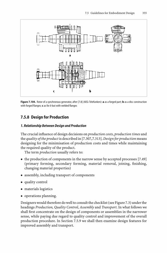
7.5 Guidelines for Embodiment Design 355
Figure 7.104. Rotor of a synchronous generator, after [7.8] (AEG-Telefunken): a as a forged part; b as a disc constructionwith forged flanges; c as for b but with welded flanges
7.5.8 Design for Production
1. Relationship Between Design and Production
The crucial influence of design decisions on production costs, production times andthe quality of the product is described in [7.307,7.313]. Design for production meansdesigning for the minimisation of production costs and times while maintainingthe required quality of the product.
The term production usually refers to:
• the production of components in the narrow sense by accepted processes [7.49](primary forming, secondary forming, material removal, joining, finishing,changing material properties)
• assembly, including transport of components
• quality control
• materials logistics
• operations planning.
Designers would therefore do well to consult the checklist (see Figure 7.3) under theheadings Production, Quality Control, Assembly and Transport. In what follows weshall first concentrate on the design of components or assemblies in the narrowersense, while paying due regard to quality control and improvement of the overallproduction procedure. In Section 7.5.9 we shall then examine design features forimproved assembly and transport.

356 7 Embodiment Design
Design for production is greatly facilitated if, from the earliest possible stage,decisions are backed up with data compiled by the standards department, theplanning and estimating department, the purchasing department and the pro-duction manager. Figure 1.4 shows how the flow of information can be improvedby systematic means, appropriate organisational measures and integrated dataprocessing.
By observing the basic rules of simplicity and clarity (see Section 7.3), designersare already proceeding along the correct lines. The principles of embodimentdesign (see Section 7.4) can also lead them to a better and safer fulfilment ofa given function and to the best solution from a production point of view. Anotherstep in the same direction is the application of general and company standards(see Section 7.5.13).
2. Appropriate Overall Layout Design
The overall layout design, developed from the function structure, determines thedivision of a product into assemblies and components and:
• identifies the source of the components; that is, whether they are in-house,bought-out, standard or repeat parts
• determines the production procedure; for instance whether the parallel produc-tion of individual components or assemblies is possible
• establishes the dimensions and the approximate batch sizes of similar compo-nents, and also the means of joining and assembly
• defines suitable fits
• influences quality control procedures.
Conversely, production limitations such as the capacity of machines, assembly andtransport facilities, etc., naturally have repercussions on the choice of the overalllayout.
The appropriate subdivision of the overall layout can give rise to differential,integral, composite and/or building-block methods of construction.
Differential Construction Method
Differential construction refers to the breakdown of a component (a carrier ofone or several functions) into several easily produced parts. This idea comes fromlightweight engineering [7.135,7.325], where this approach was introduced for thepurpose of optimising load-carrying capacity. In both cases, we are entitled tospeak of the “principle of subdivision for production”.
To show an example of the differential method, let us consider the rotor ofa synchronous generator (see Figure 7.104). The large forging shown at the top a isdivided into several rotor discs consisting of simple forged parts and two consid-erably smaller flanged shafts b. Each of the latter can also be subdivided into shaft,disc support flange and coupling flange, in the form of a welded construction c.

7.5 Guidelines for Embodiment Design 357
The reason for this differential construction might be the market situation oflarge forgings (price, delivery date), and the easier adaptation of the generator tovarious output requirements (rotor sizes) and types of coupling. A further advan-tage is that the parts can be produced as stock and not necessarily to a specificorder. However, the illustration also demonstrates the limitations of the differen-tial approach—beyond a certain rotor length and diameter, the machining costsbecome too great and the stiffness of the joints too problematical.
Another example is shown in Figure 7.105. In the winding machine a, the wind-ing head is integrated with the drive unit on a common shaft. The differentialsolution b was developed to facilitate the parallel production of drive units andwinding heads to meet various customer requirements. In this way, a small num-ber of standard drive units can be combined with a large number of windingheads.
The differential construction method also influences the production time. Fig-ure 7.106 shows an example of the production procedure for a medium-poweredelectric motor. The times spent on acquiring the material and on producing the
Figure7.105. Windingmachine (Ernst Julius KG):awindingheadwith integrateddrive unit;bwindingheadwith separatedrive unit

358 7 Embodiment Design
Figure 7.106. Production procedure for an electric motor from the series shown in Figure 9.17 (AEG-Telefunken)
components and assemblies are indicated by the lengths of the horizontal lines.The diagram not only makes clear where improvements can be made by choos-ing more quickly procurable raw and semi-finished materials or by keeping thesematerials in stock, but also where different production steps could be taken inparallel. Thus, by allowing the stator laminations to be built up in parallel withthe construction of the housing (two time-consuming operations), a significantreduction in the overall production schedule is possible in comparison to olderdesigns in which the stator laminations could only be inserted, followed by thewindings, after the casing had been welded. All in all, differential designs have theadvantages, disadvantages and limitations listed below:

7.5 Guidelines for Embodiment Design 359
Advantages:
• use of easily available and favourably priced semi-finished materials or standardparts
• easier acquisition of forged and cast parts
• easier adaptation to existing factory layout (dimensions, weight)
• increase in component batch sizes
• reduction in component dimensions allowing easier assembly and transport
• simpler quality assurance (more homogeneous materials)
• easier maintenance, for instance by simple replacement of worn parts
• easier adaptation to special requirements
• reduced risk of missing delivery dates
• reduced overall production time.
Disadvantages and limitations:
• greater machining outlay
• greater assembly costs
• greater need for quality control (smaller tolerances, necessary fits, etc.)
• limitations of function because of joints (stiffness, vibration, sealing).
Integral Construction Method
By the term integral construction we mean the combination of several partsinto a single component. Typical examples are cast constructions instead ofwelded constructions, extrusions instead of connected sections, welded in-stead of bolted joints, etc. This method is often used for product optimisa-tion because of the economic benefits of integrating several functions intoone component. This method can indeed be an advantage for specific tech-nical, production and procurement situations, particularly for labour-intensiveproduction.
Figure 7.107 shows an example chosen from electrical engineering. Here, a castand welded construction has been replaced with a single cast component. Thoughthe casting is fairly complicated, it leads to a cost reduction of 36.5%. Nat-urally, this percentage will vary with the size of the batch and with marketconditions.
Another example is the rotor of a hydroelectric generator (see Figure 7.108).Four different constructions with the same generator output and identical radialloads were investigated. Variant a has numerous individual support discs and maytherefore be considered to be a differential construction. In variant b, the degreeof division is reduced by the use of cast steel hollow shafts, two support rings and
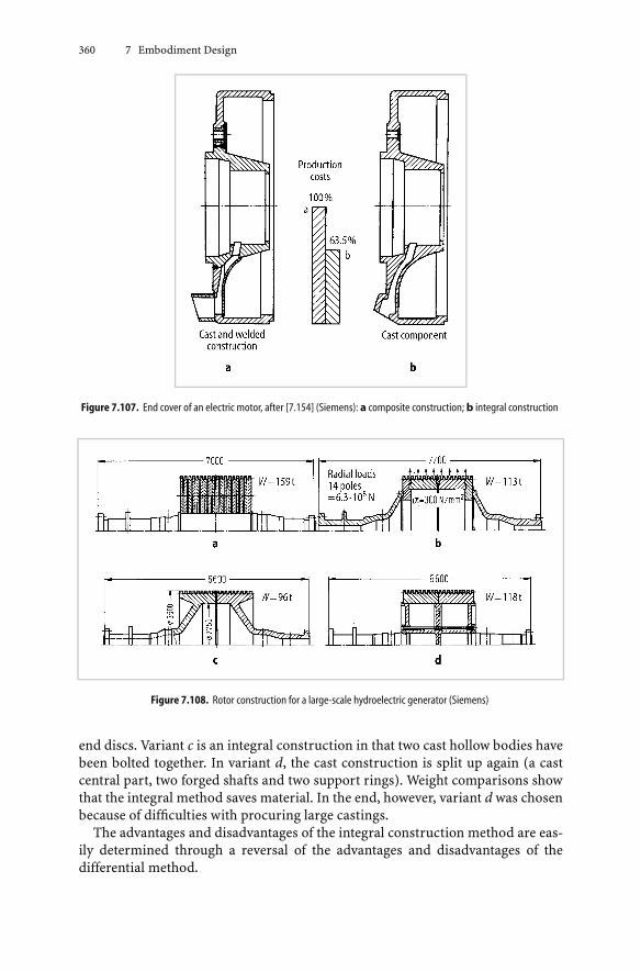
360 7 Embodiment Design
Figure 7.107. End cover of an electric motor, after [7.154] (Siemens): a composite construction; b integral construction
Figure 7.108. Rotor construction for a large-scale hydroelectric generator (Siemens)
end discs. Variant c is an integral construction in that two cast hollow bodies havebeen bolted together. In variant d, the cast construction is split up again (a castcentral part, two forged shafts and two support rings). Weight comparisons showthat the integral method saves material. In the end, however, variant d was chosenbecause of difficulties with procuring large castings.
The advantages and disadvantages of the integral construction method are eas-ily determined through a reversal of the advantages and disadvantages of thedifferential method.

7.5 Guidelines for Embodiment Design 361
Composite Construction Method
By composite construction we mean:
• the inseparable connection of several, differently made, parts into a single com-ponent necessitating further work; for instance, the combination of cast andforged parts
• the simultaneous application of several joining methods for the combination ofcomponents [7.221]
• the combination of various materials for the optimal exploitation of their prop-erties [7.290]
Figure 7.109 gives an example of the first method: the combination of cast steelcomponents and rolled steel sheet into a welded construction.
Further examples are bogies with cast centres and welded arms, and also thewelding of cast bar joints used in steel structures. Examples of the second methodarecombinationsofadhesivesandrivetsorofadhesivesandbolts.Thecombinationof several materials into a single part is exemplified by synthetic components withcast-in thread inserts; by composite sound-absorption panels which have twoplates separated by a plastic core; and also by rubber/metal components.
Another economical designof the composite type is theuseof steel inprestressedconcrete [7.120].
Figure 7.109. Magnet wheel of a hydroelectric generator of composite construction, after [7.15] (AEG-Telefunken): a Hubof cast steel; b Spoke of rolled steel sheet; c Support of cast steel
Building Block Construction Method
If the differential method is used to split a component in such a way that theresulting parts and/or assemblies can also be used in other products or product

362 7 Embodiment Design
variants, then they can be considered to be building blocks. These are particularlyuseful if they are economical to produce. In a sense, the utilisation of repeat partsfrom stock can also be considered to be a building block construction method (seeSection 9.2).
3. Appropriate Form Design of Components
During the form design of components, designers exert a great influence on pro-duction costs, production times and the quality of the product. Therefore, theirchoices of shapes, dimensions, surface finishes, tolerances and fits affect the selec-tion of:
• production procedures
• types of machines, including tools and measuring instruments
• in-house components and bought-out components, preferably making use ofrepeat parts from within the company or suitable standard and off-the-shelfcomponents
• materials and semi-finished materials
• quality control procedures.
Conversely, production facilities influence the design features. Thus, the avail-able machine tools might limit the dimensions of components, necessitating thatthey be split up into several connected parts or that bought-out componentsbe acquired. Many guidelines are available for the appropriate form design ofcomponents [7.19, 7.21, 7.123, 7.180, 7.198, 7.201, 7.262, 7.281, 7.283, 7.285, 7.287,7.288, 7.291, 7.331–7.333]. Because of the importance of tolerances (geometry,dimension, position and surface) for the production and assembly of compo-nents, we specifically suggest the following literature: [7.36, 7.38, 7.39, 7.47, 7.143,7.144].
It is important to use a tolerancing basis appropriate for the specific require-ments [7.143]. A distinction is made between the independent basis, where di-mensions are toleranced and checked individually, and the envelope basis, wheregeometrical features (such as a circle or pair of parallel surfaces) have an en-veloping tolerance zone (maximum material condition) within which the dimen-sion must lie. The latter cannot control deviations in position. For both toler-ancing bases, deviations of position are independent of dimensional tolerances.The difference is whether deviations of geometry should be within the enve-lope. A fit has to remain within the envelope and, using the independent ba-sis, this is indicated on the drawing with a fit specification, for example H7-j8.When the independent basis is used, blanket tolerances for geometry and posi-tion should be indicated. The envelope basis only requires a blanket tolerance forposition [7.143, 7.144].
In keeping with the aims of this book, we shall present only essential designsuggestions arranged systematically in the form of charts. Our classifying crite-ria will be production processes [7.48–7.50] with their individual process steps

7.5 Guidelines for Embodiment Design 363
(PS). In addition, we shall be assigning objectives—reduction of costs (C) andimprovement of quality (Q)—to the various design guidelines. When designingcomponents, designers should always bear these process steps and objectives inmind.
Form Design for Primary Shaping Processes
The form design of components to be shaped by primary processes, for examplecasting and sintering, must satisfy the demands and characteristics of the processesused.
In cast components (primary shapes obtained from the fluid state), designersmust allow for the followingprocess steps: pattern (Pa), casting (Ca) andmachining(Ma). Figure 7.110 lists the most important design guidelines. The literature citedcontains further information.
When designing sintered components (primary shapes obtained from the pow-der state), designers must allow for tooling (To) and sintering (Si). In particular,they must be guided by the latest findings in powder technology. The essentialguidelines are shown in Figure 7.111.
Form Design for Secondary Shaping Processes
The form design of components to be shaped by secondary processes (ham-mer (free) forging, drop forging, cold extrusion, drawing and bending) mustadhere to the guidelines listed below. Special considerations for the designof ferrous materials can be found in DIN 7521 to 7527 [7.46] and the de-sign of nonferrous metals in DIN 9005 [7.51]. With hammer forging, designersneed only allow for the actual forging process, since no complicated devices,for instance dies, are involved. The following design guidelines should be ob-served:
• Aim at simple shapes, if possible with parallel surfaces (conical transitions aredifficult) and with large curvatures (avoid sharp edges). Objectives: reduction ofcosts, improvement of quality.
• Aim at light forgings, perhaps by separation and subsequent combination. Ob-jective: reduction of costs.
• Avoid excessive deformations or excessive differences in cross-sections due, forinstance, to the presence of excessively high and fine ribs or of excessively narrowindentations. Objective: improvement of quality.
• Try to place bosses and indentations on just one side. Objective: reduction ofcosts.
Design guidelines for drop forging have been collated in Figure 7.112. They allowfor the process steps of: tooling (To), forging (Fo) and machining (Ma).
Figure 7.113 lists design guidelines for the cold extrusion of simple rotationallysymmetrical solid and hollow bodies. They allow for the process steps of tooling(To) and extrusion (Ex). It must be stressed that only certain types of steel can

364 7 Embodiment Design
Figure 7.110. Design guidelines with examples for cast components, after [7.123, 7.180, 7.198, 7.230, 7.331, 7.332]

7.5 Guidelines for Embodiment Design 365
Figure 7.111. Design guidelines with examples for sintered components, after [7.106]
be used economically. Like all other cold forming methods, cold extrusion givesrise to work hardening, in which the yield strength is raised while the toughnessof the material drops significantly. Designers must take this factor into considera-tion. The best materials for cold extrusion are case-hardening and heat-treatablesteels.
For drawing, the following design guidelines are recommended in [7.230]:
• Allow for tooling (To): choose the dimensions in such a way that the small-est number of drawing steps possible are needed. Objective: reduction ofcosts.
• Allow for tooling and drawing (To/Dr): aim at rotationally symmetrical hollowbodies; producing the corners of rectangular hollow bodies leads to high loadingof the materials and tools. Objectives: improvement of quality, reduction ofcosts.
• Allow for drawing (Dr): choose tough materials. Objective: improvement ofquality.
• Allow for drawing (Dr): for the design of flanges see [7.201]. Objective: improve-ment of quality.
Bending (cold bending), as used for the production of sheet metal componentsin precision and electrical engineering as well as for casings, claddings and airducts in general mechanical engineering, involves two separate steps: cutting (Cu)and bending (Be). Designers must therefore allow for both. The design guidelinesshown in Figure 7.114 apply to the bending process alone; cutting is covered underthe next heading.

366 7 Embodiment Design
Figure 7.112. Design guidelines with examples for drop-forged parts, after [7.19, 7.145, 7.230, 7.238, 7.336]
Form Design for Separation
Of the separating procedures mentioned in DIN 8577 and 8580 [7.48, 7.49], weshall only consider “machining with geometrically defined cuts” (turning, boring,milling), “machining with geometrically undefined cuts” (grinding), and “sepa-rating” (cutting). In all separating processes, designers must allow for tooling (To),including clamping, as well as machining (Ma).

7.5 Guidelines for Embodiment Design 367
Figure 7.113. Design guidelines with examples for cold extrusions, after [7.108]
Design for tooling involves:
• The provision of adequate clamping facilities. Objective: improvement of quality.
• A preferential sequence of operations that does not necessitate the reclampingof components. Objectives: reduction of costs, improvement of quality.
• The provision of adequate tool clearances. Objective: improvement of quality.
Design for machining in all separating processes involves:
• The avoidance of unnecessary machining; that is, the reduction of machined ar-eas, fine surface finishes and close tolerances to the absolute minimum (protrud-ing bosses and cut-outs placed at the same height or depth are advantageous).Objective: reduction of costs.
• The location of machined surfaces parallel or perpendicular to the clampingsurfaces. Objectives: reduction of costs, improvement of quality.
• The choice of turning and boring in preference to milling and shaping. Objective:reduction of costs.
Figure7.115 represents thedesignguidelines for componentsmachinedby turning;Figure 7.116 shows them for components machined by boring; Figure 7.117 forcomponents machined by milling; and Figure 7.118 for components machined bygrinding.
In the design of cut-out components, the characteristics of the tools (To) andthe cutting method (Cu) [7.19, 7.230] must be taken into consideration (see Fig-ure 7.119).

368 7 Embodiment Design
Figure 7.114. Design guidelines with examples for bent parts, after [7.1, 7.19]
Form Design for Joining
Of the joining methods discussed in DIN 8593 [7.50], we shall only considerwelding under the above heading. For separable joints, the reader is referred toSection 7.5.9, “Design for Ease of Assembly”.
Welding involves three process steps, namely preparation (Pr), welding (We)and finishing (Fi). The following design guidelines apply:

7.5 Guidelines for Embodiment Design 369
Figure 7.115. Design guidelines with examples for components machined by turning, after [7.180, 7.230]
Figure 7.116. Design guidelines with examples for components machined by boring, after [7.180, 7.198, 7.230]
• Pr, We, Fi: avoid the imitation of cast designs; preferably select standard, easilyobtainable or prefabricated plates, sections or other semi-finished materials;make use of composite constructions (cast/forged components). Objective: re-duction of costs.
• We: adapt the material, welding quality and welding sequence to the requiredstrength, sealing and shape. Objectives: reduction of costs, improvement ofquality.
• We: aim for short weld seams and small weld cross-sections to reduce damagethrough heating and to simplify handling. Objectives: improvement of quality,reduction of costs.

370 7 Embodiment Design
Figure 7.117. Design guidelines with examples for components machined by milling, after [7.180, 7.230]
Figure 7.118. Design guidelines with examples for components machined by grinding, after [7.230]
• We,Fi: minimise the amount of welding (heat input) to avoid or reduce dis-tortion and corrective work. Objectives: improvement of quality, reduction ofcosts.
Further guidelines are given in Figure 7.120.

7.5 Guidelines for Embodiment Design 371
Figure 7.119. Design guidelines for cut-out components, after [7.19, 7.230]
4. Appropriate Selection of Materials and of Semi-Finished Materials
An optimum choice of materials and semi-finished materials is difficult to makebecause of interactions between the characteristics of the function, working prin-ciple, layout and form design, safety, ergonomics, production, quality control, as-sembly, transport, operation, maintenance, costs, schedules and recycling. Whenthe material costs of a proposed solution are particularly high, careful materialselection becomes of the utmost economic importance (see Chapter 11). In gen-eral, designers are advised to consult the checklist (see Figure 7.3) and to evaluatethe materials accordingly. The chosen materials and the resulting processing and
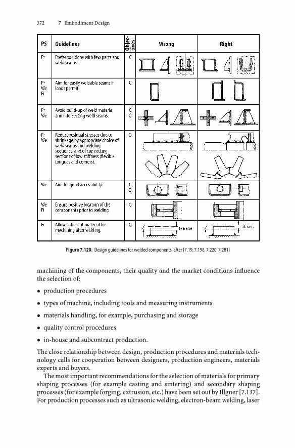
372 7 Embodiment Design
Figure 7.120. Design guidelines for welded components, after [7.19, 7.198, 7.220, 7.281]
machining of the components, their quality and the market conditions influencethe selection of:
• production procedures
• types of machine, including tools and measuring instruments
• materials handling, for example, purchasing and storage
• quality control procedures
• in-house and subcontract production.
The close relationship between design, production procedures and materials tech-nology calls for cooperation between designers, production engineers, materialsexperts and buyers.
The most important recommendations for the selection of materials for primaryshaping processes (for example casting and sintering) and secondary shapingprocesses (for example forging, extrusion, etc.) have been set out by Illgner [7.137].For production processes such as ultrasonic welding, electron-beam welding, laser

7.5 Guidelines for Embodiment Design 373
technology, plasma cutting, spark erosion and electrochemical processes, see thefollowing literature [7.27, 7.95, 7.133, 7.182, 7.240, 7.250, 7.262].
Closely connected with the selection of materials is the choice of semi-finishedmaterials (for example tubes, standard extrusions, etc.). Because of the commonmethod of costing by weight, designers tend to think that cost reduction invariablygoes hand-in-hand with weight reduction. However, as Figure 7.121 makes clear,this belief is often mistaken.
The following example throws further light on this problem. Figure 7.122 showsa welded electric motor housing. The old layout required eight different platethicknesses to achieve the required stiffness with minimum weight. In the mod-
Figure 7.121. Cost areas for lightweight and economical constructions, after [7.297]
Figure 7.122. Electric motor housing of welded construction (Siemens): a current design; b proposed design

374 7 Embodiment Design
ified design, however, the number of plate thicknesses was deliberately reduced,although this increased the weight. This change in the design involved the replace-ment of standard flame cutting by numerically controlled machines. The extraoutlay was to be justified by keeping the programming and re-equipping costslow, and through maximum utilisation of the plate material by stacking beforecutting [7.5]. A cost analysis showed that, despite an increase in weight due tooversizing of some of the housing parts, the new design was cheaper than theold thanks to lower labour costs and lower production overheads. Admittedly, theactual saving was not very great, but this example serves to show that the minimi-sation of weight, which often involves a great deal of design and production effort,does not necessarily lead to minimum costs. Moreover, even when the calculatedcost reductions resulting from the incorporation of semi-finished materials andsimplification in production processes are not great, the actual savings may bemuch greater because of the consequent reduction in idle time and time spent onoperations scheduling (see Chapter 11).
A further example of the economic use of semi-finished materials is given inFigure 7.123, which shows the plate-cutting plan for a welded motor housing. Toallow the use of circular blanks for the end-wall bearing shields d, the end-wallsare made from four parts b which are then welded together. The resulting aperture,even after machining, is smaller than the bearing shield made from the blank. Inaddition, this arrangement provides the support feet c.
Figure 7.123. Electric motor housing. Welded construction with plate-cutting plan, after [7.162] (Siemens)
5. Appropriate Use of Standard and Bought-Out Components
Designers should always try to use components that do not have to be speciallyproduced but that are readily available as repeat, standard, or bought-out parts.In this way, they can help to create favourable supply and storage conditions.
7.5 Guidelines for Embodiment Design 375
Easily available bought-out parts are often cheaper than parts made in-house. Theimportance of standard parts has already been stressed on several occasions.
The decision on whether components should be made in-house or bought-outdepends on the following considerations:
• number (one-off, batch or mass production)
• whether production is for a specific order or for the general market
• market situation (costs, delivery dates of materials and bought-out parts)
• available production facilities
• utilisation of existing production facilities
• available or desired degree of automation.
These factors influence not only the decision on whether in-house production isto be preferred to subcontract production, but also the design approach. Unfortu-nately, most of the factors vary with time. This means that a particular decisionmay be justified at the time that it was made, but it may no longer be correct ifthe market situation and the production capacity change. Particularly in the caseof one-off or batch products in the heavy engineering industry, the market andproduction situation needs to be re-examined at regular intervals.
6. Appropriate Documentation
The effect of production documents (in the form of CAD models, drawings, partslists and assembly instructions) on costs, delivery dates, product quality, etc., isoften underestimated. The layout, clarity and comprehensiveness of such docu-ments have a particularly marked influence. They determine the execution of theorder, production planning, production control and quality control.
7.5.9 Design for Assembly
1. Types of Assembly
Designers not only have a major influence on the costs (see Chapter 11) and thequality of the production of components, but also on the costs and quality ofassembly [7.329].
By assembly we refer to the combination of components into a product and tothe auxiliary work needed during and after production. The cost and quality of anassembly depend on the type and number of operations and on their execution.The type and number, in their turn, depend on the layout design of the product,on the form design of the components and on the type of production (one-off orbatch production).
The following guidelines for design for assembly can therefore be no more thangeneral hints [7.2, 7.32, 7.101, 7.102, 7.316, 7.318, 7.329]. The aims of the guidelinesare to simplify, standardise, automate and ensure quality. In individual cases,they may be influenced or overridden by referring to the following headings in thechecklist (seeFigure7.3): Function,WorkingPrinciple, Layout, Safety,Ergonomics,

376 7 Embodiment Design
Production, Quality Control, Transport, Operation, Maintenance and Recycling.The particularities of specific cases must be checked [7.132, 7.170, 7.171, 7.223,7.289].
According to Guideline VDI 3239 [7.309] and [7.3,7.268], the following essentialoperations are involved:
• Storing (St) of parts to be assembled, if possible in a systematic manner. Au-tomatic assembly further necessitates the programmed supply of parts andconnecting elements.
• Handling (Ha) of components, including:• identifying the part by fitter or robot, e.g. by checking its orientation
• picking up the part, if necessary in conjunction with individual selection anddispensing
• moving the part to the assembly point, if necessary in conjunction withseparation (removal, rejection, etc.), manipulation (rotation, inversion, etc.)and combining components.
• Positioning (Po) (placing the part correctly for assembly), and aligning (finaladjustment of the position of the part before and possibly after joining).
• Joining (Jo) parts by the provision of appropriate connections. According toDIN 8593 [7.50], the following operations must also be included here:• bringing together, for example by inserting, superposing, suspending or fold-
ing
• filling, for example by soaking
• pressing together, for example by bolting, clamping or shrink-fitting
• joining by primary processes, for example by fusing, casting and vulcanising
• joining by secondary processes, for example by bending or via auxiliarycomponents
• joining by the combination of materials, for instance by welding, soldering orgluing.
• Adjusting (Ad) to equalise tolerances, to restore the required play, etc. [7.269].
• Securing (Se) the assembled parts against unwanted movements under opera-tional loads.
• Inspecting (In). Depending on the degree of automation, various testing andmeasuringoperationsmustbeperformed,possiblybetween individual assemblyoperations.
These operations are involved in every assembly process, their importance, se-quence and frequency depending on the number of units (one-off assembly, batchassembly) and the degree of automation (manual, part automatic or fully automaticassembly).
According to [7.112], the linking of assembly operations or assembly cells can bedivided into the following types: unbranched, branched, single level and multilevelassembly. The assembly process can be stationary or flowing.

7.5 Guidelines for Embodiment Design 377
It is also important to distinguish whether assembly takes place within the com-pany or on site, by experts or by less well trained customer personnel. In general,the improvements one can make to automate assembly will also simplify manualassembly and vice versa. The selected type of assembly and the embodiment areclosely related, that is, they influence one another.
2. General Guidelines for Assembly
In accordance with the steps of the embodiment design phase (see Section 7.1),it seems useful to start considering assembly even while working on the work-ing structure and the layout. An easy-to-assemble layout can be achieved if theassembly operations are:
• structured
• reduced
• standardised
• simplified.
This will lead to a reduction in expenditure because the assembly process isimproved and to increase in product quality because assembly is clearer and easierto control [7.94,7.105,7.257]. A layout that has been selected for these reasons couldalso lead a reduction in the number of components or at least the standardisationof components.
The embodiment guidelines that focus on ease of assembly are classified inFigure 7.124. The column operation contains the assembly operations that are pri-marily affected by the specific embodiment guidelines. The third column indicateswhether the guideline leads to an improvement of manual assembly (MA) or auto-mated assembly (AA), or both. This classification should ease the use and selectionof embodiment guidelines for specific assembly situations.
3. Designing Assembly Interfaces
Another important aspect of improving assembly is the design of interfaces thatare influenced by the layout. Improvements to the interfaces are achieved if theyare:
• reduced
• standardised
• simplified.
These actions reduce the number of connecting elements and assembly operations,and minimise the quality requirements of the interfacing elements [7.2, 7.112,7.273].
In Figure 7.125, the embodiment guidelines are again classified according to theaims and the affected assembly operations.

378 7 Embodiment Design
Figure 7.124. Embodiment guidelines for designing the layout for assembly

7.5 Guidelines for Embodiment Design 379
Figure 7.124. (continued)

380 7 Embodiment Design
Figure 7.125. Embodiment guidelines for designing the interfaces for assembly

7.5 Guidelines for Embodiment Design 381
Figure 7.125. (continued)
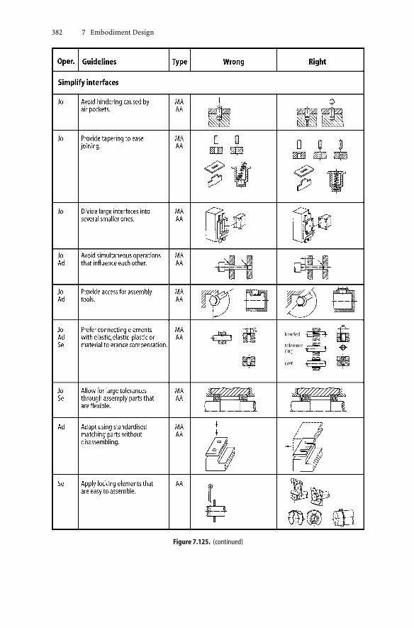
382 7 Embodiment Design
Figure 7.125. (continued)
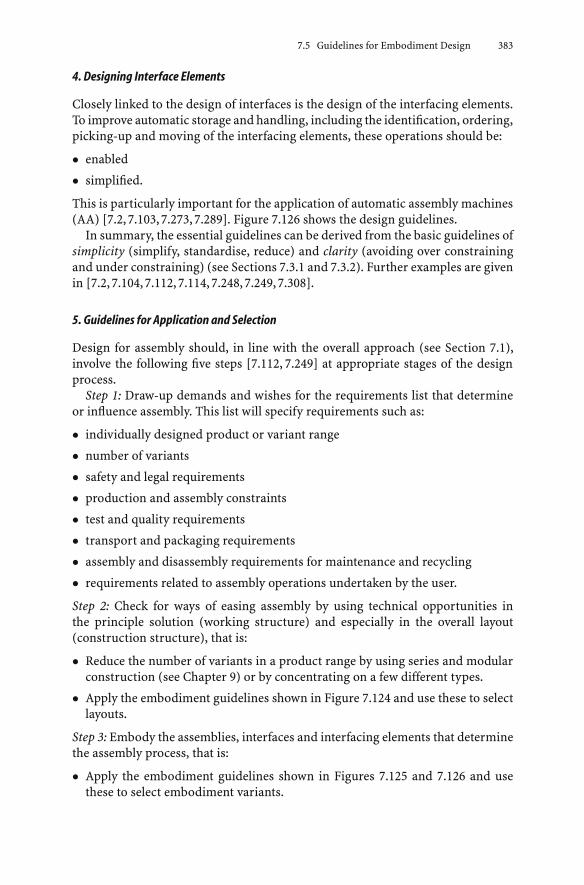
7.5 Guidelines for Embodiment Design 383
4. Designing Interface Elements
Closely linked to the design of interfaces is the design of the interfacing elements.To improve automatic storage and handling, including the identification, ordering,picking-up and moving of the interfacing elements, these operations should be:
• enabled
• simplified.
This is particularly important for the application of automatic assembly machines(AA) [7.2, 7.103, 7.273, 7.289]. Figure 7.126 shows the design guidelines.
In summary, the essential guidelines can be derived from the basic guidelines ofsimplicity (simplify, standardise, reduce) and clarity (avoiding over constrainingand under constraining) (see Sections 7.3.1 and 7.3.2). Further examples are givenin [7.2, 7.104, 7.112, 7.114, 7.248, 7.249, 7.308].
5. Guidelines for Application and Selection
Design for assembly should, in line with the overall approach (see Section 7.1),involve the following five steps [7.112, 7.249] at appropriate stages of the designprocess.
Step 1: Draw-up demands and wishes for the requirements list that determineor influence assembly. This list will specify requirements such as:
• individually designed product or variant range
• number of variants
• safety and legal requirements
• production and assembly constraints
• test and quality requirements
• transport and packaging requirements
• assembly and disassembly requirements for maintenance and recycling
• requirements related to assembly operations undertaken by the user.
Step 2: Check for ways of easing assembly by using technical opportunities inthe principle solution (working structure) and especially in the overall layout(construction structure), that is:
• Reduce the number of variants in a product range by using series and modularconstruction (see Chapter 9) or by concentrating on a few different types.
• Apply the embodiment guidelines shown in Figure 7.124 and use these to selectlayouts.
Step 3: Embody the assemblies, interfaces and interfacing elements that determinethe assembly process, that is:
• Apply the embodiment guidelines shown in Figures 7.125 and 7.126 and usethese to select embodiment variants.

384 7 Embodiment Design
Figure 7.126. Embodiment guidelines for designing interface elements for assembly

7.5 Guidelines for Embodiment Design 385
• Take into account special production and assembly restrictions (batch size;available machine tools; manual, semi-automatic or automatic assembly).
• Select connecting elements and processes not only based on functional require-ments (strength, sealing, and corrosion resistance) but also based on require-mentsof assembly anddisassembly (easeof looseningduringdisassembly, reuse,potential for automation).
• Consider production and assembly costs together.
Step 4: Evaluate embodiment variants technically and economically, paying par-ticular attention to the required interfacing procedures, that is:
• Evaluate the ease of assembly of a design, preferably as soon as the princi-ple solution is established. Designers should work together with the productionplanning department, because the assembly plan (assembly sequence and struc-ture [7.112]) and the assembly processes and tools, including quality control,cannot be determined by designers alone. One way to aid the development of anassembly plan is to mentally divide the overall layout drawing into its individualelements; that is, to start by drawing up a disassembly plan. The inverse of thiscan then provide the basis for the assembly plan of the product. It can also beuseful to simulate the assembly process using computer-supported productionand assembly planning (CAP) and the production of prototypes.
• Assess the assembly process in terms of the supply of subcontract, bought-outand standard parts.
• Derive evaluation criteria from the goals and embodiment guidelines listed inFigures7.124 to7.126, adapting themwherenecessary to theparticular situation.
Step 5: Prepare detailed assembly instructions together with the production doc-uments. This includes overall layout drawings for subassemblies and the product(preassembly and final assembly), the assembly parts list and other assembly in-formation.
7.5.10 Design for Maintenance
1. Goals and Terminology
Technical systems and products are subject to wear and tear, reduction of usefullife, corrosion, contamination and changes in time-dependent material properties,such as embrittlement. After a certain period of time, whether in use or not, the ac-tual condition of a system will no longer be the intended one. Deviations from theintended condition cannot always be recognised directly and can cause changes inperformance, failures and dangerous situations. This can substantially reduce thefunctionality, economy and safety of a technical system. Sudden breakdowns dis-rupt normal operation, and because they are unexpected they require considerablecost to rectify. Not checking the condition of a system until damage has occurred,possibly involving injury, is unacceptable from both human and economic pointsof view.

386 7 Embodiment Design
Because systems and products have become more complex, the application ofmaintenance as a preventative measure has become increasingly important. De-signers have a significant influence on maintenance costs and procedures throughtheir selection of the principle solution and embodiment features, which accordingto [7.62, 7.304] strongly determine maintainability. We have already emphasisedthe importance of maintenance in our systematic approach; for example in theguidelines (see Sections 2.1.7 and 5.2.3, Figure 5.3, Section 6.5.2, and Figure 6.22)and their application in connection with the basic rules (see Section 7.3). More re-cent publications [7.139,7.151] emphasise the importance of an early considerationof maintainability and a systematic approach.
Maintenance is related to safety (see Section 7.3.3), ergonomics (see Sec-tion 7.5.6) and assembly (see Section 7.5.9). As the sections in this book addressingthese topics already include suggestions and rules relevant to maintenance, thissection focuses on what is necessary for a general understanding of maintenanceand on design for ease of maintenance.
According to DIN 31051 [7.62], maintenance involves monitoring and assessingthe actual condition of a system and maintaining or recovering the intendedcondition.
Possible measures are:
• Service, to maintain the intended condition
• Inspection, to monitor and assess the actual condition
• Repair, to recover the intended condition.
The type, extent anddurationof service and inspectionmeasuresobviouslydependon the type of system, its intended function, its required availability, its desiredreliability, and on any potential dangers. The selected measures determine whetherinspection and service has to take place after a fixed period of time, after a specificnumber of operating hours, or after a particular intensity of load.
The maintenance strategy is also influenced by the rate of deterioration ofcomponents, for example through wear that reduces operating life. The measuresapplied to recover the intended condition must be taken before components arepredicted to fail. Accordingly, two types of repair are distinguished:
• Failure repair that takes place after a component has failed. This strategy isapplied, and is often the only possibility, when failures cannot be predicted ac-curately. It is important that such failures do not cause danger. The disadvantageof this approach is the effect it has on planning. An example is the shatteringof a car windscreen. This strategy is not suitable for production plant, and insituations where a function must be fulfilled or where danger is involved.
• Preventive repair that takes place before a component has failed. This can be de-termined by either interval or condition. Interval repair takes place after a fixedperiod of time, a specific distance or a set number of operations. An example iswhen the oil in an vehicle engine is changed after 10 000 km. Condition repairis based on actual performance measures, such as the loads or temperaturesexperienced in operation. When an unwanted condition is observed, the service

7.5 Guidelines for Embodiment Design 387
or repair measures must be carried out. An example of this is when the oil ina vehicle engine is changed after a certain number of cold starts, or the integratedaverage temperature of the oil reaches a certain value. Another example is whenbrake linings are replaced after a measured amount of wear. Whether the intervalor condition strategy is applied depends on the operating conditions. A combi-nation of the two strategies is also possible. A power station, for example, willuse the time interval repair strategy to safeguard the base load. For componentsthat can last several intervals, the condition repair strategy will be adopted.
More detailed discussions of maintenance strategies can be found in [7.282,7.304].Predictions of both the probability of failure and component reliability are dis-cussed in [7.232].
2. Design for Maintenance
Maintenance requirements should have been included in the requirements list,see Figure 5.3 and VDI 2246, Part 2 [7.304]. When solutions have to be selected,easily maintained variants should be preferred. Examples are variants that requireminimal servicing, include components that can be exchanged easily, and usecomponents with similar life expectancies. During the embodiment phase, it isimportant to consider accessibility and ease of assembly and disassembly. However,design for maintenance should never compromise safety.
According to [7.282], a technical solution should, in principle, require as fewpreventative measures as possible. The aim is complete freedom from the need forservice by using components with identical lives, reliability and safety. The chosensolution should thus incorporate features that make maintenance unnecessary orreduce it substantially.
Only when such features cannot be realised or are too costly should service andinspection measures be introduced. In principle, the following aims are important:
• Prevent damage and increase reliability.
• Avoid the possibility of errors during disassembly, reassembly and start-up.
• Simplify service procedures.
• Make the results of servicing checkable.
• Simplify inspection procedures.
Service measures usually concentrate on refilling, lubricating, conserving andcleaning. These activities should be supported by embodiment features and appro-priate labelling based on ergonomic, physiological and psychological principles.Examples are easy access, nontiring procedures and clear instructions.
Inspection measures can be reduced to a minimum when the technical solu-tion itself embodies direct safety techniques, see Section 7.3.3, and thus promiseshigh reliability. Overloading, for example, can be avoided by using appropriateprinciples such as self-help that provide protection against failures and disturbinginfluences, see Section 7.4.3. When service and inspection measures cannot beavoided, embodiment guidelines, discussed earlier, should be applied [7.282]. Inwhat follows, we limit ourselves to lists and short explanations.

388 7 Embodiment Design
Technical measures that can reduce the service and inspection effort, and shouldhave been considered already in the conceptual phase, include:
• Prefer self-balancing and self-adjusting solutions.
• Aim at simplicity and few parts.
• Use standard components.
• Allow easy access.
• Provide for easy disassembly.
• Apply modular principles.
• Use few and similar service and inspection tools.
Service, inspection and repair instruction documents have to be prepared, andservice and inspection points have to be labelled clearly. Guidance on develop-ing maintenance manuals can be found in DIN 31052 [7.63], and guidance ondetermining maintenance intervals in DIN 31054 [7.64].
To facilitate the execution of service, inspection and repair measures, the fol-lowing ergonomic rules, supported by appropriate technical embodiments, shouldbe applied:
• Service, inspection and repair locations should be easily accessible.
• The working environment should follow safety and ergonomic requirements.
• Visibility should be ensured.
• Functional processes and supporting measures should be clear.
• Damage localisation should be possible.
• Exchange of components should be easy.
Instructive examples for each of these requirements can be found in [7.282].Finally, maintenance should be part of the total concept. Maintenance pro-
cedures must be compatible with functional and operational constraints of thetechnical system, and must be included in the overall cost along with the purchaseand operating costs.
7.5.11 Design for Recycling
1. Aims and Terminology
To save and reuse raw materials in order to move towards more sustainable de-velopment, the following possibilities can be considered [7.141,7.142,7.169,7.186,7.197, 7.218, 7.302, 7.305, 7.321]:
• reducing material use through better utilisation (see Section 7.4.1) and by re-ducing waste during production (see Section 7.5.8)
• substituting materials for those becoming rare and expensive [7.9]
• recycling materials by reusing or reprocessing production waste, products andparts of products.

7.5 Guidelines for Embodiment Design 389
In what follows, possible types of recycling and recycling processes are explainedbased on VDI Guideline 2243 [7.302]. They help us to understand the embodimentguidelines that support recycling (see Figure 7.127).
Production waste recycling involves reusing production waste in a new produc-tion process, for example offcuts (after they have been preprocessed).
Product recycling involves reusing a product or part of it, for example reusinga vehicle’s engine (after it has been reconditioned).
Used material recycling is the reuse of old products and materials in a newproduction process, for example the reprocessing of materials from scrappedvehicles (after they have been preprocessed). These secondary materials or partsdo not necessarily have a lower quality than new materials or parts, in which casethey can be reused. When the quality is significantly reduced, they can only beused for other purposes.
Preprocessing and reconditioning make significant contributions to effectiverecycling.
The materials left over from the recycling system end up in waste dumps or inthe environment. It is possible that in the future these materials will also be usedas resources.
Various methods of recycling are possible within the recycling loops shown inFigure 7.127. Basically one can distinguish between reusing products and repro-cessing products.
Reuse involves retaining the product shape whenever possible. This type ofrecycling represents a high level of utilisation and should therefore be aimed for.Two types of reuse can be distinguished. In the first, the product fulfils the samefunction, e.g. refillable gas cylinders, and in the second a different function, e.g.reusing car tyres as boat fenders.
Reprocessing destroys the product shape, and so this process leads to a lowerutilisation value. Two types of reprocessing can be distinguished. In the first, re-processing takes place for application in the same product production process,e.g. reprocessing the materials from scrapped vehicles; in the second, reprocess-ing takes place for a different application, e.g. converting old plastic into oil bypyrolysis.
2. Recycling Processes
Preprocessing
The reprocessing of production waste and scrap materials is influenced stronglyby the necessary preprocessing methods [7.186, 7.197, 7.277, 7.302].
Compacting of loose scrap by pressing eases the process of charging in metalmaking, butdoesnot allow the separationofmaterials inmixed scrap. It is thereforeonly suitable for the recycling of unmixed production waste and scrap metals, e.g.food cans.
Cutting heavy or large products can be done with shears or flame cutting. Thesemethods are particularly suitable when the materials have to be separated after-wards.

390 7 Embodiment Design
Figu
re7.
127.
Poss
ibili
tiesf
orre
cyclin
g,af
ter[
7.18
6,7.
302]

7.5 Guidelines for Embodiment Design 391
Separating can take place in a shredding plant based on the principle of a ham-mer pulveriser, in which a rotating hammer tears the product apart. In serieswith this pulveriser are other processes, such as dust removal, magnetic separa-tion, size separation, and manual sorting of materials. Shredded scrap has highquality because of its high density, purity and uniform piece size. These tech-nically complex and labour-intensive preprocessing methods are used for about80% of scrapped vehicles and about 20% of scrapped domestic products, e.g.refrigerators. Grinders provide the same waste quality. They are just as techni-cally complex, differing only in the method of pulverising used prior to materialseparation.
Figure 7.128. Operating principles and material flow in a shredding pant: a shredder, 1 dust removal, 2 sorting conveyors;b magnetic separation; c float/sink testing; d rotary kiln
392 7 Embodiment Design
Float/sink testing can be linked to shredders and grinders for improved separa-tion of nonferrous and nonmetallic parts. Dropping weights can be used to reducelarge grey iron castings with large wall thicknesses. Chemical preprocessing can beused to separate harmful materials and alloys before they are used again in metalmaking.
Figure 7.128 illustrates the material flow in a modern shredding plant [7.302].Because plastics now make up a large proportion of scrap, it is becoming in-
creasingly important to recycle these materials [7.18, 7.109]. The preprocessing ofthermoplastics can be achieved through shredding, washing, drying and granulat-ing, provided this waste has been presorted. This is difficult for household waste.The preprocessing of mixed plastic waste can be performed by mechanical separa-tion, such as sorting, sizing and sieving, after it has been broken down into smallerparts. Other methods of separating include the use of electrostatics and floatationfor density testing. Such preprocessing methods are still under development, sothe sorting of plastics prior to collection would provide an economically viablealternative. Chemical preprocessing can be used for thermosetting plastics andelastomers [7.184].
The best waste and scrap quality—that is, the highest material reutilisationrate—is achieved by disassembling the product prior to preprocessing. Such dis-assembly into appropriate material groups can be undertaken by either specialistcompanies or by the product manufacturers themselves on dedicated disassemblylines.
The prerequisites for economic disassembly should be established by de-signers through the selected embodiment features and assembly methods (seeSection 7.5.9). Economic preprocessing of scrap products and materials in-volves an appropriate combination of disassembly and preprocessing meth-ods [7.186, 7.302].
Reconditioning
In order to be able to reuse products after they have been used for the first time,a reconditioning process that comprises the following steps is required [7.197,7.266, 7.267, 7.302, 7.319]:
• complete disassembly
• cleaning
• testing
• reuse of worthwhile parts, repair of worn areas, reworking of parts to be adapted,replacement of unusable parts with new ones
• reassembly
• testing.
Two methods are used to recondition products, whether this is undertaken inspecial companies or by the product manufacturers [7.10]. The first method retainsthe identity of the original product; that is, while changing and reworking parts theconfiguration of the parts is retained and the tolerances are matched to each other.

7.5 Guidelines for Embodiment Design 393
For example, an engine reconditioned using this method will retain its originalengine number. The second method breaks up the original product in such a waythat all parts are treated as new ones along with their individual tolerances. Theresult is that the reconditioned original parts and the new parts are combined atthe reassembly stage as if they were all new. This method has a promising futurebecause the same production and assembly facilities can be used for both thereconditioned and original products.
3. Design for Recycling
To support preprocessing and reconditioning procedures, designers can intro-duce specific measures during product development [7.12–7.14, 7.22, 7.141, 7.142,7.186, 7.187, 7.196, 7.302, 7.320, 7.321, 7.323]. These measures, however, must notconflict with the other goals and requirements of the task (see Figure 2.15). Inparticular, the cost effectiveness of production and operation must be guaran-teed.
Recycling Considerations During the Design Process
Recycling possibilities should be considered during all stages of the design process(see Figures 1.9, 6.1, 7.1, 8.1). Figure 7.129 shows which recycling related designtasks should be undertaken in each of the design phases set out in VDI Guideline2221 [7.270, 7.323].
Embodiment Guidelines for Preprocessing
The following guidelines relate to the overall product and the individual assem-blies. They can be applied singly or in combination, with the aim of improvingpreprocessing or direct reprocessing.
Material compatibility. It is very difficult to design products made from a singlematerial that can be reprocessed easily. For indivisible units, therefore, the aimshould be to use materials that are compatible with regard to reprocessing. Thisresults in an output from the process that is more economical and has higherquality.
To fulfil this aim, the production requirements for reprocessing need to beknown. Here it is useful to define so-called scrap material groups or base ma-terials to which compatible materials are assigned. Until such generally appli-cable groups are identified by materials scientists and the materials process-ing industry, designers should check the material compatibility in each casewith experts. This is particularly important for large batch production withhigh recycling potential. Figure 7.130 shows a sample compatibility table forplastics.
Material separation. When material compatibility cannot be realised for insep-arable parts or assemblies, additional interfaces should be introduced to breakproducts down in such a way that the incompatible materials can be separatedduring preprocessing, for example through disassembly.
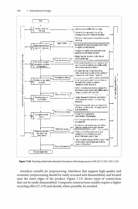
394 7 Embodiment Design
Figure 7.129. Recycling-related tasks allocated to the phases of the design process in VDI 2221 [7.270, 7.293, 7.323]
Interfaces suitable for preprocessing. Interfaces that support high-quality andeconomic preprocessing should be easily accessed and disassembled, and locatednear the outer edges of the product. Figure 7.131 shows types of connectionsthat can be easily disassembled. Composite constructions usually require a higherrecycling effort [7.119] and should, where possible, be avoided.
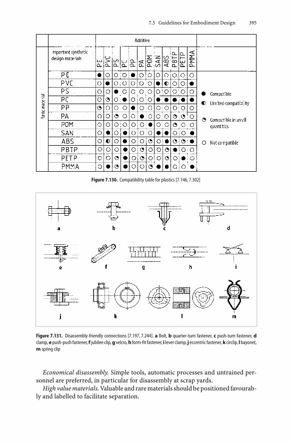
7.5 Guidelines for Embodiment Design 395
Figure 7.130. Compatibility table for plastics [7.146, 7.302]
Figure 7.131. Disassembly-friendly connections [7.197, 7.244]. a Bolt, b quarter-turn fastener, c push-turn fastener, dclamp,epush-push fastener, f jubilee clip,g velcro,h form-fit fastener, i lever clamp, j eccentric fastener,k circlip, lbayonet,m spring clip
Economical disassembly. Simple tools, automatic processes and untrained per-sonnel are preferred, in particular for disassembly at scrap yards.
Highvaluematerials. Valuable and rarematerials shouldbepositioned favourab-ly and labelled to facilitate separation.

396 7 Embodiment Design
Dangerous materials. Materials, liquids and gases that can be dangerous tohumans and the environment during preprocessing or direct reprocessing shouldalways be easy to separate or remove.
Embodiment Guidelines for Reconditioning
The following guidelines should be applied:
• Ensure easy and damage-free disassembly (see [7.134,7.160,7.194,7.270] for fur-ther disassembly guidelines and Figure 7.132 for concepts that ease disassemb-ly—also compare with Section 7.5.9).
• Ensure that all reusable parts can be cleaned easily and without damage.
• Facilitate testing and sorting through appropriate embodiment.
• Ease the reworking of parts or the deposition of material by providing additionalmaterial and facilities for locating, clamping and measuring.
• Ease reassemblybyusingexisting tools fromone-off andsmall batchproduction.
To reduce the number of new parts that are needed, the following measures areuseful:
• Limit wear to special-purpose, easily adjustable or exchangeable parts (see Sec-tions 7.4.2 and 7.5.5).
• Make it easy to identify the state of wear of a part and to decide whether it canbe reused.
• Ease material deposition on areas of wear by selecting appropriate base materi-als.
• Minimise corrosion through embodiment and protective measures to increasethe reusability of parts (see Section 7.5.4).
• Select connections that function throughout the product life yet can be easilyundone, do not slacken after repeated disconnecting, and are not subject tocorrosion bonding [7.245, 7.286].
Labelling of Recycling Possibilities
The recycling possibilities and the required recycling procedures for assembliesand modules should be labelled in line with the proposed recycling strategy and theembodiment developed to fulfil that strategy. This allows easy and safe adoption ofthe required recycling processes and measures. Figure 7.133 provides an exampleof the labelling of plastic parts.
4. Examples of Design for Recycling
Recycling of Plain Pedestal Bearings (Used Material Recycling)
Plain pedestal bearings (see Figure 9.25) are so common in machines that it iseconomic to consider recycling. The first possibility is to recycle by reconditioning

7.5 Guidelines for Embodiment Design 397
Figure 7.132. Embodiment guidelines for ease of disassembly [7.197, 7.244]
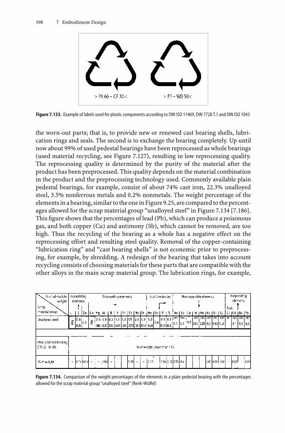
398 7 Embodiment Design
Figure 7.133. Example of labels used for plastic components according to DIN ISO 11469, DIN 7728 T.1 and DIN ISO 1043
the worn-out parts; that is, to provide new or renewed cast bearing shells, lubri-cation rings and seals. The second is to exchange the bearing completely. Up untilnow about 99% of used pedestal bearings have been reprocessed as whole bearings(used material recycling, see Figure 7.127), resulting in low reprocessing quality.The reprocessing quality is determined by the purity of the material after theproduct has been preprocessed. This quality depends on the material combinationin the product and the preprocessing technology used. Commonly available plainpedestal bearings, for example, consist of about 74% cast iron, 22.3% unalloyedsteel, 3.5% nonferrous metals and 0.2% nonmetals. The weight percentage of theelements inabearing, similar to theone inFigure9.25, are compared to thepercent-ages allowed for the scrap material group “unalloyed steel” in Figure 7.134 [7.186].This figure shows that the percentages of lead (Pb), which can produce a poisonousgas, and both copper (Cu) and antimony (Sb), which cannot be removed, are toohigh. Thus the recycling of the bearing as a whole has a negative effect on thereprocessing effort and resulting steel quality. Removal of the copper-containing“lubrication ring” and “cast bearing shells” is not economic prior to preprocess-ing, for example, by shredding. A redesign of the bearing that takes into accountrecycling consists of choosing materials for these parts that are compatible with theother alloys in the main scrap material group. The lubrication rings, for example,
Figure 7.134. Comparison of the weight percentages of the elements in a plain pedestal bearing with the percentagesallowed for the scrap material group “unalloyed steel” (Renk-Wülfel)

7.5 Guidelines for Embodiment Design 399
could be made out of an aluminium alloy with a low copper content (for exampleAlMg3), and the bearing shell from grey cast iron, with or without a plastic coating.
Recycling of White Goods (Used Material and Product Recycling)
White goods such as washing machines, dishwashers, refrigerators, etc., are valu-able for recycling because they are produced in large numbers and contain valu-able materials. Figure 7.135 shows the weight percentages of the main materials ina dishwasher. There are numerous nonferrous metals and nonmetals, and a par-ticularly high percentage of high alloy steels. Preprocessing the product as a wholeby, for example, shredding is not economic because the high alloy steels cannot bereprocessed separately. In addition, the nonferrous metals complicate the repro-cessing process, or at least increase the reprocessing effort. A product structuremore suitable for reprocessing would comprise main assemblies that are easy to
Figure 7.135. Material weight percentages of an AEG dishwasher from 1979/80, after [7.186]

400 7 Embodiment Design
separateordisassemble so that they canbepreprocessed separatelyby, for example,shredding, cutting or compacting. This might also enable the reuse of individualcomponents or even the whole product (product recycling).
Figure 7.136 shows an embodiment variant for the dishwasher. In this embod-iment, the base 1 contains all of the accessories including a circulating pump 2,a water distribution pump 3, a washing detergent pump 4, and the electronics 5.This base assembly has been designed so that no connecting elements are requiredfor the components. They are simply kept in place by the lower part of the casing 6.The casing and the base can be opened and closed by means of the hinge 7. Themaximum angle achieved after tilting the casing is large enough to assemble all thecomponents and to remove them for recycling (preprocessing or reconditioning).
Another example of white goods is shown in Figure 7.137. Different variantsof a washing machine were produced by varying the construction structure ofthe housing and the location of the functional components. A Use-Value Analysisshowed that variant B is the best because it has a lower number of parts and a lowernumber of reassembly interfaces, which is not only beneficial for recycling but alsofor maintenance.
Figure 7.136. Dishwasher designed for recycling (Bosch-Siemens)

7.5 Guidelines for Embodiment Design 401
Figure 7.137. Construction structure variants of a washing machine (after Löser, TU Berlin). 1 Dispenser; 2 programmecontrol; 3 display; 4 door; 5 socket and fuses; 6 power electronics; 7 detergent pump; 8 heater; 9 1/4-turn fastener; 10 centralelectrical unit
Disassembly-Friendly Drive Assembly
Figure 7.138 shows the drive assembly of a hammer drill in which the locatingbearing of the motor shaft is not retained axially by the usual circlip, which inprinciple is easy to disassemble, but by a U-shaped clip that can be pulled out toseparate the drive assembly from the motor. The reason for this solution is thata circlip would not be accessible in this assembly.
When developing products that are easier to recycle, particular care must betaken to ensure that they are not more expensive than traditional solutions as faras production and assembly are concerned.

402 7 Embodiment Design
Figure 7.138. Disassembly-friendly gearbox of a hammer drill (Bosch) [7.118]
5. Evaluating Recycling Potential
When developing new products, it is necessary to evaluate solution variants againsttheir potential for recycling [7.160,7.222]. Recycling criteria can simply be includedin the evaluation procedure discussed in Section 3.3.2.
Figure 7.139 lists evaluation criteria, which are divided into those related toproduct recycling and those related to material recycling. To determine the overallrating, the recycling rating can be combined with the technical/economic ratingof a product. S-diagrams and value profiles can be used, in particular those thatshow the distance of a solution variant from an imaginary ideal solution (seeSection 3.2.2) [7.11,7.118], to illustrate the individual rating and the overall rating.
Such evaluation procedures can be extended into a product impact assess-ment [7.118, 7.263, 7.264, 7.324].
7.5.12 Design for Minimum Risk
Despite provisions against faults and disturbing factors (see Chapter 10), design-ers will still be left with gaps in their store of information and with evaluationuncertainties: for technical and economic reasons, it is not always possible to covereverything with theoretical or experimental analyses. Sometimes all designerscan hope to do is to set limits. Thus, despite the most careful approach, somedoubt may remain as to whether the chosen solution invariably fulfils the func-tions laid down in the requirements list or whether the economic assumptionsare still justified in a rapidly changing market situation. In short, a certain riskremains.
Onemightbe tempted to alwaysdesign in suchaway that thepermitted limits arenot exceeded, and to obviate any impairment of the function or early damage by de-signing a technical system to operate below its potential capacity. Experienced de-signers know that with this approach they rapidly encounter another risk: the cho-

7.5 Guidelines for Embodiment Design 403
Figure 7.139. Evaluation criteria for product and material recycling, after [7.118, 7.197]
sen solution becomes too large, too heavy or too expensive and can no longer com-pete in the market. The lower technical risk is offset by the greater economic risk.
1. Coping with Risks
Faced with this situation, designers must ask themselves what countermeasuresthey can take; provided, of course, that the solution was carefully chosen in the firstplace and that the appropriate guidelines were scrupulously followed. The essentialapproach is that designers must, on the basis of the analysis of faults, disturbingfactors and weak spots, provide a substitute solution to counter the possibility thatthe original solution might not cover all uncertainties.
In the systematic search for solutions, several solution variants should havebeen elaborated and analysed. In that case, the advantages and disadvantages ofindividual solutions will have been discussed and compared, which may have ledto a new and improved solution. As a result, designers will be familiar with therange of possible solutions; they will have been able to rank them and also to takestock of the economic constraints.
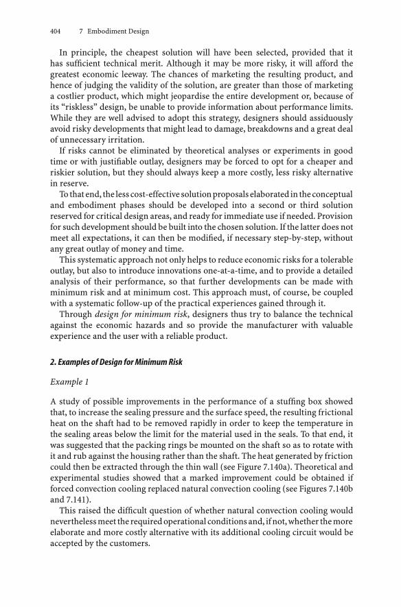
404 7 Embodiment Design
In principle, the cheapest solution will have been selected, provided that ithas sufficient technical merit. Although it may be more risky, it will afford thegreatest economic leeway. The chances of marketing the resulting product, andhence of judging the validity of the solution, are greater than those of marketinga costlier product, which might jeopardise the entire development or, because ofits “riskless” design, be unable to provide information about performance limits.While they are well advised to adopt this strategy, designers should assiduouslyavoid risky developments that might lead to damage, breakdowns and a great dealof unnecessary irritation.
If risks cannot be eliminated by theoretical analyses or experiments in goodtime or with justifiable outlay, designers may be forced to opt for a cheaper andriskier solution, but they should always keep a more costly, less risky alternativein reserve.
To thatend, the lesscost-effective solutionproposals elaborated in theconceptualand embodiment phases should be developed into a second or third solutionreserved for critical design areas, and ready for immediate use if needed. Provisionfor such development should be built into the chosen solution. If the latter does notmeet all expectations, it can then be modified, if necessary step-by-step, withoutany great outlay of money and time.
This systematic approach not only helps to reduce economic risks for a tolerableoutlay, but also to introduce innovations one-at-a-time, and to provide a detailedanalysis of their performance, so that further developments can be made withminimum risk and at minimum cost. This approach must, of course, be coupledwith a systematic follow-up of the practical experiences gained through it.
Through design for minimum risk, designers thus try to balance the technicalagainst the economic hazards and so provide the manufacturer with valuableexperience and the user with a reliable product.
2. Examples of Design for Minimum Risk
Example 1
A study of possible improvements in the performance of a stuffing box showedthat, to increase the sealing pressure and the surface speed, the resulting frictionalheat on the shaft had to be removed rapidly in order to keep the temperature inthe sealing areas below the limit for the material used in the seals. To that end, itwas suggested that the packing rings be mounted on the shaft so as to rotate withit and rub against the housing rather than the shaft. The heat generated by frictioncould then be extracted through the thin wall (see Figure 7.140a). Theoretical andexperimental studies showed that a marked improvement could be obtained ifforced convection cooling replaced natural convection cooling (see Figures 7.140band 7.141).
This raised the difficult question of whether natural convection cooling wouldneverthelessmeet the requiredoperational conditionsand, ifnot,whether themoreelaborate and more costly alternative with its additional cooling circuit would beaccepted by the customers.

7.5 Guidelines for Embodiment Design 405
Figure 7.140. Cooled stuffing box in which the packing revolves with the shaft. Appropriate design of the shaft andpress ring ensures the internal connection of the packing rings; a very short heat path facilitates good heat extraction.a Heat extraction by natural convection currents in the surrounding medium, dependent on the prevailing air flow;b heat extraction by forced convection due to separate cooling air flow, ensuring higher flow velocities and increased heatextraction
The minimum risk decision—that is, to construct the housing in such a way thateither cooling system could easily be used—helped the designers gain experiencefor only a small increase in cost.
Example 2
In the development of a series of high-pressure steam valves operating at tem-peratures of more than 500◦C, the question arose as to whether the customarymethod of nitriding the valve spindles and bushes should be retained despite thefact that the nitrided surface expands with temperature (thereby reducing the ra-dial clearance), or whether very much more expensive stellite hard facing wouldhave to be substituted. When the problem first arose, there was a lack of adequateinformation about the long-term behaviour of such layers at high temperatures.The minimum risk solution adopted was to select wall thicknesses and dimensionsof valve spindles and bushes such that, if necessary and without changing theother components, stellite-treated parts could be substituted for the others. As itturned out, the operating temperature range was considerably lower than had beenanticipated, so that nitriding provided a satisfactory solution and also helped to

406 7 Embodiment Design
Figure 7.141. Theoretical and experimental temperatures at the seal, plotted against the peripheral speed on the shaft: alayout as in Figure 7.140a; b layout as in Figure 7.140b; c conventional stuffing box with packing attached to the housing
identify the operational limits. Once these limits were known, the more expensivesolution could be reserved for more demanding conditions.
Example 3
Reliable design calculations for large machine parts, particularly in one-off pro-duction, depend on the analytical methods and the postulated constraints. It is notalways possible to predict all characteristics with the necessary degree of accuracy.This applies, for instance, to the determination of the critical whirling speeds ofshafts. Often it is impossible to predict the precise flexibility of the bearings andfoundations. However, the difference between higher critical whirling speeds inhigh-speed installations is small within the range of flexibilities normally encoun-tered. In the situation depicted in Figure 7.142, minimum risk design can once

7.5 Guidelines for Embodiment Design 407
again be applied advantageously because the spacing of the bearings, which hasa major influence on the critical speed, can be adjusted (see Figure 7.143). In-terposed spring laminations (see Figure 7.144), moreover, allow alteration of theeffective flexibilities. Both measures, taken together or separately, will produce the
Figure 7.142. Critical whirling speeds (qualitative) for a shaft plotted against the flexibility of bearings and foundations
Figure 7.143. Support that allows the distances between the bearings to be varied through the selection of differentspacers

408 7 Embodiment Design
Figure 7.144. Plain bearings with laminated springs 1 that allow the flexibility to be adjusted (laminated springs also havegood clamping properties, thus narrowing the critical range)
required effect so that the second or third critical whirling speeds can be eliminatedfrom the operating speed range of the machine.
Example 4
Among the many suggestions put forward for a device to wind a strip into a double-layered ring, two seemed particularly promising (see Figures 7.145a and b).
The solution shown in Figure 7.145a is the simpler and cheaper but also theriskier of the two, because it is not certain whether the inner rotating mandrel 1alone is invariably able—despite the increased friction produced by the knurlingand the pressure of the springs 2—to move the strip 3 forward.
The solution shown in Figure 7.145b is less risky, because the pressure rollersattached to the ends of the springs and the feed roller 5, which moreover can bepower-driven, make the advance of the strip more certain. This solution, however,is the more costly of the two, and also more susceptible to wear because of thegreater number of small moving parts.
The minimum risk solution is to adopt the one shown in Figure 7.145a, but witha feed-in roller as in Figure 7.145b, and arranged in such a way that, if necessary,it can be driven without alteration of the other parts, see Figure 7.145c. Thisadditional feed-in roller proved essential when the machine was tested, and wasreadily available.

7.5 Guidelines for Embodiment Design 409
Figure 7.145. a Proposed winding device: 1 rotating mandrel, 2 pressure springs, 3 strip to be wound, 4 parts of theejection mechanism; b proposed winding device: 1 rotating mandrel, 2 springs with pressure rollers, 3 strip to be wound,4 parts of the ejection mechanism, 5 feed-in roller loaded by spring and possibly driven; c Chosen solution: 1 rotatingmandrel, 2 pressure springs, 3 strip to be wound, 5 feed-in roller tensioned by spring 6 and driven by belt 7
Example 5
In complex ventilation systems it is often very difficult to precalculate the airflowand pressure losses precisely. An embodiment with minimum risk for ventilatorsmight have blades that can be adjusted before they are welded to the disc. Whenenough experience has been gained, it is possible to substitute a nonadjustableand cheaper cast construction.
All of these examples are intended to show that designers should meet risks not bysimply considering the first potential problem but by also considering the secondand third, which can often be done at relatively minor cost. Experience has shownthat the application of emergency measures to correct unforeseen faults is manytimes more costly and time consuming.

410 7 Embodiment Design
7.5.13 Design to Standards
1. Objectives of Standardisation
If we examine the systematic approach outlined in this book in the light of theminimisation of effort, we are bound to ask to what extent can generally ap-plicable function carriers be determined and documented so that designers canhave ready access to tested solutions; that is, to known elements and assemblies.This has also been raised in connection with standardisation which, according toKienzle [7.149], can be defined as follows: “Standardisation lays down the defini-tive solution of a repetitive technical or organisational problem with the besttechnical means available at the time. It is therefore a form of technical and eco-nomic optimisation limited by the time factor.” Further definitions can be foundin [7.34, 7.85].
Standardisation considered as the unification and determination of solutions,for instance in the form of national and international standards (BSI, DIN, ISO), ofcompany standards, or of generally applicable design catalogues, and also of datasheets, is becoming of increasing importance in systematic design. Here, the factthat the objectives of standardisation are to limit the range of possible solutions inno way conflicts with the systematic search for a multiplicity of solutions, becausestandardisation is largely confined to the determination of individual elements,subsolutions, materials, computation and testing procedures, etc., while the searchfor a multiplicity of solutions and their optimisation is based on the combinationor synthesis of known elements and data. Standardisation is therefore not simplyan important complement to but a prerequisite of the systematic approach, inwhich various elements are combined as so many building blocks.
Traditionally, the speed of research and development allowed standards tobe formulated only after the relevant knowledge had been verified and provenin practice. Today, the pace of change, for example in information technology,means that regulations and standards regarding new technologies increasinglyhave to depend on less well-tested knowledge. This situation is has arisen dueto the need to remain competitive in a global market and to influence the di-rection of further developments. Development and standardisation therefore gohand-in-hand [7.98, 7.128, 7.226], resulting in the increasing publication of pre-standards.
In what follows, we shall be examining the possibilities of, the need for, and thelimits of standards in the design process. In addition, the reader is referred to theliterature [7.34, 7.85, 7.89–7.93, 7.129, 7.150, 7.216, 7.220, 7.227].
2. Types of Standard
The following discussion of types of standard is meant to:
• encourage designers to make wide use of standards
• invite them to suggest new standards or, at the very least, to influence thedevelopment of standardisation

7.5 Guidelines for Embodiment Design 411
• remind them of the crux of standardisation, namely, the systematic arrangementof facts with a view to their unification and optimisation in the light of functionalconsiderations.
In terms of their origin, we distinguish between:
• national standards of the BSI (British Standards Institution) or the DIN (Deut-sche Institut für Normung: the German Standards Institution)
• European (EN) standards of the CEN (Comité Européen de Normalisation) andCENELEC (Comité Européen de Normalisation Electrotechnique)
• recommendations and standards of the IEC (International ElectrotechnicalCommission)
• recommendations and standards of the ISO (International Organisation forStandardisation).
In terms of their content, we distinguish, for instance, between communicationstandards, classification standards, type standards, planning standards, dimen-sional standards, material standards, quality standards, procedural standards,operational standards, service standards, test standards, delivery standards andsafety standards.
In terms of their scope, we distinguish between basic standards (general andinterdisciplinary standards) and special standards (standards used in specialistfields).
Besides the national and international standards we have mentioned, designerscan also refer to the rules and regulations published by professional engineeringinstitutions, e.g. VDI, ASME, IMechE. These are important as they pave the wayfor further standardisation after initial trials.
Designers can also refer to a variety of internal company standards and regula-tions [7.86–7.88]. These can be classified as follows:
• compilations of representative standards; that is, a selection of general standardsthat are applicable to the special requirements of a particular company, such asstock lists and comparisons of old with new standards (synoptic standards)
• catalogues, lists and data sheets on bought-out parts, including their storage andalso data on the acquisition (ordering/supplying) of raw materials, semi-finishedmaterials, fuels, etc.
• catalogues or lists of in-house parts, for instance machine elements, repeat parts,standard solutions, assemblies, etc.
• information sheets used for technical and economic optimisation, for instancethose on production capacity, production methods, cost comparisons (see Sec-tion 11.3.2).
• rules and regulations for the calculation and embodiment design of machineelements, assemblies, machines and plant, if necessary with a selection of sizesand/or types

412 7 Embodiment Design
Figure 7.146. Relation between company, national, European and international standards based on DIN
• information sheets on storage and transport resources
• regulations concerning quality control, for example inspection and testing pro-cedures
• rules and guidelines for the preparation and processing of information, for in-stanceofdrawings,parts lists,numberingsystemsandelectronicdataprocessing
• rules laying down organisational and working procedures, for instance the up-dating of parts lists and drawings.
The relation between company, national, European and international standardsis shown in Figure 7.146. Company standards are developed or selected for spe-cific products or processes and adapted to the actual situation. This implies thattheir depth and actuality is high. National and international standards requirea longer period of development, but are more generally applicable. The vari-ety and depth of these standards is generally lower. It is more difficult to adaptthem to changes and therefore their dissemination and effects are more impor-tant.
3. Preparing Standards
Searching for and using standards, regulations and other information duringthe design process requires considerable effort. There are various ways in whichinformation is made available: folders with standards, BSI or DIN handbooksand guides, microfiche and increasingly computer databases. These databases arenow being integrated into CAD systems, providing designers not only with thetextual information contained in standards, but also with the geometry of thecomponents [7.6, 7.124, 7.238, 7.239].

7.5 Guidelines for Embodiment Design 413
4. Using Standards
Although there are no absolutely binding standards in the legal sense at the timeof writing, national and international standards are widely treated as regulations,adherence to which is of great advantage in the case of legal disputes. This isparticularly true of safety standards [7.23, 7.57, 7.115, 7.254, 7.303].
In addition, all company standards should be considered binding within theirsphere of application, not least for economic reasons.
The sphere of application of a given standard is largely set by Kienzle’s definition(see above). A standard can only be valid and binding if it does not conflictwith technical, economic, safety or even aesthetic demands. Even in the case ofsuch conflicts, however, designers should guard against rejecting or replacingthe relevant standards out of hand, without assessing the possible consequences.Moreover, they should never make such assessments by themselves, but shouldalways consult the standards organisation and the head of department.
In what follows, a number of recommendations and hints for the correct use ofstandards are listed.
First of all, we recommend adherence to national basic standards since otherstandards are based on these and the preferred sizes laid down in them help todetermine the dimensions of all components. If these basic standards are ignored,then unpredictable long-term consequences (for instance, in the provision of spareparts) and grave technical and economic risks may ensue.
The use of standards should be examined against the checklist provided inSection 7.2, as illustrated by the following examples.
Layout
The basic and special standards—especially constructional, dimensional, materialand safety—must be fully taken into account. Testing and inspection proceduresalso influence the embodiment.
Safety
Established component, work and environmental safety standards and regulationsmust be rigorously observed. Safety standards must always be given precedenceover rationalisation procedures and economics.
Production
Here, the observance of production standards is particularly important and thatof factory regulations is binding. This necessitates the continual updating of therelevant standards. Designers should only deviate from production standards aftera broad assessment of all the industrial and relevant market (purchase and sales)aspects.
Quality Control
Test standards and inspection rules are essential features of quality control.

414 7 Embodiment Design
Maintenance
Standard symbols (for instance, circuit diagrams) should be used and servicestandards should be provided.
Recycling
For reuse and reprocessing, test, material, quality, dimensional, production andcommunication standards are particularly important.
The above recommendations on the use of standards are by no means exhaust-ive—the work of designers is much too varied and complex for that, and therange of general and company standards much wider than we have been ableto cover in our summary. By working their way down the checklist, designerscan tell how much a particular standard fits the various headings quickly andaccurately.
5. Developing Standards
Since designers bear much of the responsibility for the development, productionandutilisationofproducts, they shouldplay a leading role in the revisionof existingstandards, and the development of new ones.
To make a useful contribution to the development of standards, they must firstdetermine whether the revision of an existing standard or the development of a newstandard is technically andeconomically justified.There is rarely a clear-cut answerto this question. In particular, completely reliable assessments of the economicconsequences are seldom possible because of the complex effects of in-housecosts and market influences, and, in any case, they would involve considerableresearch.
The following principles of developing general standards, and particularly com-pany standards, can be set down [7.7,7.30,7.33,7.271]. Whether something shouldbe standardised depends on several prerequisites, that is, the envisaged standardmust:
• document the state of the art of the technology
• be accepted by the majority of experts in the field
• ensure the complete interchangeability of parts, for example if a standardisedproduct is modified in such a way that it can no longer be freely interchangedeven with respect to a single feature, its designation (identification number)must be altered
• only be used if it is economical and useful, that is, there must be a need
• only be altered for technical, not purely formal, reasons
• always support a simple, clear and safe solution
• not contain any provisions that conflict with the law, e.g. with monopoly restric-tions or safety regulations

7.5 Guidelines for Embodiment Design 415
• not include solutions that are protected, e.g. by patents or copyright
• not formulate design and production details
• not concern topics that are developing rapidly
• not hinder technical progress
• not allow subjectiveness or interpretation
• not standardise fashion and taste
• not endanger the safety of humans and the environment
• not serve a single individual; that is, thepeople affectedmust be consultedduringthe development and no standardisation should take place when importantgroups are opposed.
Moreover, the following aspects should be considered:
• Standards must be unambiguous, framed in clear terms and easily under-stood [7.35].
• Standard dimensions must, as far as possible, agree with preferred numberseries.
• All standards must be based on SI units [7.93].
• The layout of a standard should support its use and application. In particular, theuse of computer-based information systems should be facilitated [7.124, 7.238,7.239].
The development of a standard should generally include the following steps:
• A standard is proposed.
• The proposal is discussed in a working committee which develops a draft stan-dard.
• This draft is circulated to all interested and affected parties and modified.
• After the draft has been accepted, a pre-standard can be issued for evaluationpurposes.
• The final standard is issued.
Because a standard can be regarded as an artificial system, its preparation shouldalso follow the steps of systematic design (see Chapters 4, 6 and 7). This ensuresthe optimisation of a standard’s content and layout, and facilitates its carefuldevelopment, which can be subsequently verified.
The evaluation criteria set out in Figure 7.147, once again arranged in accor-dance with the checklist, can be of great help in the assessment of existing or newlyproposed standards if they are used in conjunction with the usual evaluation pro-cedure. Not all the evaluation criteria we have mentioned apply to the assessmentof individual standards. Thus, the evaluation of a drawing standard is influencedby its clarity; by the improvement in communication; by the simplification of thedesign activity and the overall execution of the order it provides; by the degree towhich it is generally accepted; and also by the costs its development entails. Before

416 7 Embodiment Design
Figure 7.147. Evaluation criteria for the assessment of standards
they make an evaluation, standards engineers or designers should therefore gradethe importance of the various evaluation criteria and discard those that may notapply. In much the same way as with the recommendations in Section 3.3.2, theremust be an adequate value rating to justify the development of a standard.
7.6 Evaluating Embodiment Designs
In Section 3.3.2 we discussed the subject of design evaluation. The basic proceduresoutlined there apply equally well to the conceptual and to the subsequent phases.As embodiment progresses, the evaluation will, of course, rest on more and moreconcrete objectives and properties.
In the embodiment phase, the technical properties must be evaluated in termsof the technical rating Rt and the economic properties separately with the help ofthe calculated production costs in terms of the economic rating Re. The two ratingscan then be compared in a diagram (see Figure 3.35).
The prerequisites for this approach are the following:
• All the embodiment designs have the same degree of concreteness; that is, thesame information content (for instance, rough designs must only be compared

7.7 Example of Embodiment Design 417
with rough designs). In many cases it suffices, while keeping the overall per-spective in mind, to evaluate only those aspects that show marked differencesfrom one another. Once that has been done, their relationship to the whole, ofcourse, must be examined; for example the relationship between part costs andtotal costs.
• The manufacturing costs (materials, labour and overheads) can be determined(see Chapter 11). If a particular solution introduces subsidiary costs, such as op-erating costs, and demands special investment, then—depending on the pointof view (the producer’s or the user’s)—these factors must be allowed for, ifnecessary by amortisation. In addition, optimisation can help to achieve a min-imisation of production and operating costs.
If the calculation of manufacturing costs is omitted, then the economic rating canonlybeevaluatedqualitatively, as itwas in theconceptualphase. In theembodimentphase, however, costs should, in principle, be determined more concretely (seeChapter 11).
As we mentioned in Section 3.3.2, the first step is to establish the evaluationcriteria. They are derived from:
• the requirements list:
– desirable improvement on minimum demands (how far exceeded)
– wishes (fulfilled, not fulfilled, how well fulfilled)
• the technical properties (to what extent present and fulfilled).
The comprehensiveness of the evaluation criteria can be tested against the head-ings of the checklist (see Figure 7.148), which is specially adapted to the level ofembodiment attained.
At least one significant evaluation criterion must be considered for each heading,although sometimes more will be needed. A heading may only be ignored if thecorresponding properties are absent from, or identical in, all the variants. Thisapproach avoids subjective over-valuation of individual properties. It must befollowed by the procedural steps outlined in Section 3.3.2. The economic feasibilityshould be established by this stage at the latest.
In the embodiment phase, the search for weak spots, errors and disturbinginfluences, along with their elimination, is essential, in particular when evaluatingthe final layout.
7.7 Example of Embodiment Design
The conceptual design phase involves a process that focuses mainly on functionsand working structures and results in principle solutions (concepts).
In the embodiment design phase, the emphasis is on determining the construc-tion structures of the individual assemblies and components. In VDI 2223 andin Chapter 4 (Figure 4.3) and Chapter 7 (Figure 7.1) of this book, a systematicapproach is proposed that has been tested in practice. The variations in approach

418 7 Embodiment Design
Figure 7.148. Checklist for evaluating embodiment designs
and methods needed to deal with different tasks and problems are greater in em-bodiment design than in conceptual design. Embodiment design, characterisedby a further elaboration of the selected principle solution, requires a more flex-ible approach, extensive knowledge of the relevant domain and greater experi-ence.
Explaining embodiment design using examples for different tasks would requiretoo much space. It would also be misleading because such examples might suggestthat the specific approach described is the only correct one. The example used inthe rest of this chapter is based on the principle solution discussed in Chapter 6. Itsonly purpose is to show how the main embodiment steps of Figure 7.1 are executedand linked together.
The embodiment task is the concretisation of the principle solution for theimpulse-loading test rig for shaft–hub connections (see Section 6.6.2). That sec-tion described the clarification of the task and the setting up of the requirementslist (see Figure 6.43); the identification of the essential problems through abstrac-tion (see Table 6.2); the establishment of function structures (see Figures 6.44and 6.45); the search for working principles (see Figure 6.46); the combinationof working principles into working structures (see Figure 6.47); the selection ofsuitable working structures (see Figure 6.48); their concretisation into principlesolution variants (see Figures 6.49 to 6.52); and the evaluation of these solutionvariants (see Figures 6.55 and 6.56). We now continue with the embodiment designof this example following the steps shown in Figure 7.1.

7.7 Example of Embodiment Design 419
Steps 1 and 2: Identifying Embodiment-Determining Requirementsand Clarifying Spatial Constraints
The following items from the requirements list were identified as determining theembodiment features:
• Determining layout:
test connection held in position
loading applied to stationary shaft in one direction only
hubside load take-off variable
torque input variable
no special foundation.
• Determining dimensions:diameter of shaft to be tested ≤100 mm
adjustable torque T ≤ 15 000 Nm (maintained for at least 3 s)
adjustable torque increase dT/dt = 1.25 × 10³ Nm/s
power consumption ≤ 5 kW.
• Determining material:shaft and hub: 45C.
• Other requirements:production of the test rig in own workshops
bought-out and standard parts wherever possible
easy to disassemble.
The requirements list did not contain specific spatial constraints.
Step 3: Identifying Embodiment-Determining Main Function Carriers
The basis for this step was function structure variant No 4 (see Figure 6.45) andthe principle solution variant V2 (see Figure 6.47). Table 7.6 lists the main functioncarriers used in the selected solution variant to fulfil the various subfunctions,along with their main characteristics. The function carriers that determined theembodiment are:
• the test specimen
• the lever between the cylindrical cam and the shaft of the test specimen
• the cylindrical cam.
The other main function carriers are:
• the electric motor
• the flywheel

420 7 Embodiment Design
Table 7.6. Main function carriers
Functions Function carriers Characteristics
Transform energy; increase Electric motor Power PM
energy component Speed nM
Run-up time tM
Store energy Flywheel Moment of inertia JFSpeed nF
Torque transmitted TCL
Release energy Clutch Torque transmitted TCL
Maximum speed nCL
Response time tCL
Increase energy component Gearbox Power PG
Maximum output torque TG
at output speed nG
Gear ratio RG
Control magnitude and time Cylindrical cam Power PCAM
Torque TCAM
Speed nCAM
Diameter DCAM
Cam angle αCAM
Rise hCAM
Transform energy into torque Lever Length lLStiffness sL
Load test specimen Test specimen Torque TRate of torque increase dT/ dt
Take up forces and torque Frame
• the clutch
• the gearbox
• the frame.
Step 4: Developing Preliminary Layouts and Form Designsfor the Main Function Carriers
Figure 7.149 shows a preliminary layout drawing for the three embodiment-determining function carriers.
The embodiment of the test specimen in line with DIN 6885 and of the trans-mission lever, modelled and analysed as a cantilever, were relatively straightfor-ward. The development and embodiment of the cylindrical cam, however, requireda more detailed kinematic and dynamic analysis based on specific items in the re-quirements list.
A more precise analysis showed that the initial estimates undertaken in theconceptual phase of the cylindrical cam’s performance were insufficient to proceeddirectly to embodiment. The following analysis therefore had to be carried outbefore determining the main dimensions.

7.7 Example of Embodiment Design 421
Figure 7.150 shows that:
Torque on the shaft: T = sL · hCAM · lLTorque increase: dT/ dt = π · DCAM · nCAM · tan αCAM · sL · lL
Hold time: tL =UCAM
2π · DCAM · nCAM=
12 · nCAM
The equation for the torque increase is only valid if the lever movement is parallelto the cam track. In order to minimise friction, a roller follower was required(see Figure 7.151), so the actual torque increase was lower than calculated and alsovaries.We thereforeused theaverage increase inour calculations (seeFigure 7.152).
If, in line with the requirements list, the average torque increase dT/ dt is used,then the calculation of dT/ dt should not involve the full circumferential speed vX,but instead the effective circumferential speed v∗
X, thus:
v∗X = K · vX
The correction K depends on:
• the cam angle αCAM
• the diameter of the roller follower d
• the rise of the cylindrical cam hCAM.
Figure 7.149. Main function carriers that determine the layout: 1 test connection; 2 transmission lever; 3 cylindrical cam
Figure 7.150. Geometric constraints for the cylindrical cam and lever. sL is the stiffness of the lever

422 7 Embodiment Design
The correction K was derived from Figure 7.153:
x =hCAM
tan αCAM
x = d/2 ·(
sin αCAM −1 − cos αCAM
tan αCAM
)
K =v∗
X
vX=
xx + ∆x
The formula is only valid when d/2 · (1 − cos αCAM) ≤ hCAM, for example:
K =hCAM
tan αCAM
hCAMtan αCAM
+ d/2 ·(sin αCAM − 1−cos αCAM
tan αCAM
)To obtain a value for K, the following estimates were made:
• cam angle αCAM = 10 … 45◦
Figure 7.151. Cam path and lever movement
Figure 7.152. Torque increase

7.7 Example of Embodiment Design 423
Figure 7.153. Derivation of correction K
• the diameter of the roller follower d = 60 mm
• the rise of the cylindrical cam hCAM = 7.5 mm and 30 mm, respectively.
Table 7.7 contains the values of K obtained from the above formula.After converting the cylindrical cam speed nCAM and using the calculated cor-
rection value K, the formula including torque increase dT/ dt became:
nCAM =
dTdt
K · π · DCAM · tan αCAM · sL · lL
The speed controller range C
C =nCAMmax
nCAMmin
was determined as follows.If the diameter of the cylindrical cam DCAM, the stiffness sL and the length lL
of the lever are considered constant for this solution concept, the above formulacan be used to calculate the extremes of the speed nCAM in relation to the otherparameters dT/ dt, K and αCAM (see Table 7.8).
B is a constant that includes units and the other constants (π, DCAM, sL, lL).
Table 7.7. Reference values for K corrections
hCAM mm αCAM 45◦ 40◦ 30◦ 20◦ 10◦
7.5 K 0.41 0.45 0.62 0.79 0.9430.0 K 0.71 0.76 0.87 0.94 0.98
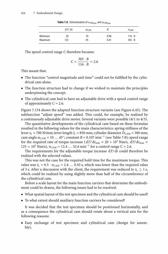
424 7 Embodiment Design
Table 7.8. Determination of nCAMmin and nCAMmax
dT/ dt αCAM K nCAM
Minimum 20 10 0.98 116 · BMaximum 125 45 0.41 305 · B
The speed control range C therefore became:
C =305 · B116 · B
= 2.6
This meant that:
• The function “control magnitude and time” could not be fulfilled by the cylin-drical cam alone.
• The function structure had to change if we wished to maintain the principlesunderpinning the concept.
• The cylindrical cam had to have an adjustable drive with a speed control rangeof approximately C = 2.6.
Figure 7.154 shows the adapted function structure variants (see Figure 6.45). Thesubfunction “adjust speed” was added. This could, for example, be realised bya continuously adjustable drive motor. Several variants were possible (4/1 to 4/3).
The quantitative developments of the cylindrical cam based on these formulaeresulted in the following values for the main characteristics: spring stiffness of thelever sL = 700 N/mm; lever length lL = 850 mm; cylinder diameter DCAM = 300 mm;cam angle αCAM = 10 … 45◦; constant B = 0.107 min−1 (see Table 7.8); speed rangefor the required rate of torque increase (dT/ dtmin = 20 × 103 Nm/s, dT/dtmax =125 × 103 Nm/s), nCAM = 12.4 … 32.6 min−1 for a control range C = 2.6.
The requirements for the adjustable torque increase dT/ dt could therefore berealised with the selected values.
This was not the case for the required hold time for the maximum torque. Thisvalue was tL = 0.5 · nCAM = 2.4 … 0.92 s, which was lower than the required valueof 3 s. After a discussion with the client, the requirement was reduced to tL ≥ 1 s,which could be realised by using slightly more than half of the circumference ofthe cylindrical cam.
Before a scale layout for the main function carriers that determine the embodi-ment could be drawn, the following issues had to be resolved:
• What spatial layout of the test specimen and the cylindrical cam should be used?
• To what extent should auxiliary function carriers be considered?
It was decided that the test specimen should be positioned horizontally, andas a consequence the cylindrical cam should rotate about a vertical axis for thefollowing reasons:
• Easy exchange of test specimen and cylindrical cam (design for assem-bly).

7.7 Example of Embodiment Design 425
Figu
re7.
154.
Func
tion
stru
ctur
eva
riant
sfor
func
tion
stru
ctur
e4,
afte
rFig
ure
6.45

426 7 Embodiment Design
• Easy access to the test specimen for measurements (design for ergonomics).
• Smooth transmission of the clamping forces of the test specimen into the foun-dation (short and direct force transmission paths).
• Easy resetting of the test rig for different types of specimen, in particular largerspecimens (design for minimum risk).
The need for auxiliary function carriers was then assessed and the space require-ments determined on the basis of experience. It was found that:
• A separate bearing was needed for the cylindrical cam because of the axial forceFA and the tangential force FT:
FA = FT =Tmax
lL= 17.6 kN
• The outer diameter of the bolted joint between test specimen and lever had tobe about 400 mm to provide a torsionally stiff connection.
The analysis showed that the auxiliary function carriers had only a marginalinfluence on the dimensions of the embodiment.
Figure 7.155a shows a preliminary layout based on function structure variant4/1, where the speed control is achieved by means of an adjustable mechanismthat is located behind the clutch in terms of the energy flow. Figure 7.155b shows
Figure 7.155. Layout of main function carriers: a for function structure variant 4/1; b for function structure variant 4/2;c for function structure variant 4/3; 1 motor, 2 flywheel, 3 adjustable gear, 4 clutch, 5 worm gear (angular), 6 cylindricalcam, 7 transmission lever, 8 test connection, 9 adjustable geared motor

7.7 Example of Embodiment Design 427
a preliminary layout based on function structure variant 4/2, where the adjustablemechanism is located before the clutch. Variant 4/3 (see Figure 7.155c) employs anadjustable geared motor.
Step 5: Selecting Suitable Preliminary Layouts
Variant 4/3 was selected for further detailing because it took up less space due tothe adjustable geared motor (function integration).
Step 6: Developing Preliminary Layouts and Form Designsfor the Remaining Main Function Carriers
The preliminary layouts and form designs for the remaining main function carrierswere based on the following requirements identified in step 4:
• motor drive speed for cylindrical cam
nCAM = 12.4…32.6 min−1
• speed control range
C = 2.6
• driving torque of cylindrical cam
TCAM = FT · DCAM/2 and FT = FA = T/lL gives TCAM = 2650 Nm
• driving power of cylindrical cam
PCAM = TCAM · ωCAM, thus PCAM = 9 kW
For reasons of safety, the maximum flywheel speed nF (and therefore also that ofthe motor nM) was chosen to be:
nF = 1000 min−1
This required a transmission ratio of:
i = 80.7…30.7
For the other main function carriers, the characteristics were estimated as follows:
• Transferred torque of the coupling based on the driving torque of the cylindricalcamTCAM = 2 650 Nmand theactual transmission ratio ibetween thecylindricalcam and clutch
TCL = TCAM/i

428 7 Embodiment Design
• Moment of inertia of the flywheel from the actual torque TF taken up by theflywheel, the impact time ∆t, the flywheel speed nF and the allowable drop inspeed ∆n = 5%
JF =TF · ∆t
2 · π · nCAM · ∆n
• The power of the electric motor PM after calculating the required accelerationtorque TA from the moment of inertia JF of the flywheel, the motor speed nM,the run-up time tM = 10 s and the maximum acceleration torque of the motorTAmax (from manufacturer’s data)
TA =JF · 2 · π · nM
tM< TAmax
Table 7.9 lists the calculated values for the main characteristics. Apart from theflywheel, the main function carriers could all be selected from catalogues andbought directly from suppliers.
The following characteristics were chosen for the flywheel:
• speed nF = 1010 min−1
• moment of inertia JF = 1.9 kg m2.
Because losses such as those from friction had not been taken into account, thefinal value of JF was chosen to be substantially larger than this.
To save weight, the flywheel was made from a hollow cylinder:
• Outer diameter Do = 480 mm
• Inner diameter Di = 410 mm
• Width W = 100 mm
• Mass m = 38 kg.
The final preliminary layout drawing was then produced on the basis of the mainfunction carriers shown in Figure 7.155c and by adding the frame.
Table 7.9. Calculated values for the characteristics of the main function carriers of variant 4/3
Functions Function carriers Calculated values
Change energy Electric motor with Power PM = 1.1 kWIncrease E-component mechanical adjustment- Speed nM = 380…1000 min−1
Adjust speed variant 4/3 Speed control range C = 2.6
Store energy Flywheel Moment of inertia JF = 1.4 kgm2
Speed nF = 380…1000 min−1
Release energy Electromagnetic clutch Transferred torque TCL = 86 Nm
Increase E-component Gear Power PG = 9 kWNominal torque TG = 2650 Nmat speed nG = 32 min−1
Transmission ratio iG = 40.7

7.7 Example of Embodiment Design 429
Figure 7.156. Final spatial constraints: 1, base plate for fixing the test machine; 2, foundation
Figure 7.157. Preliminary layout drawing for the main function carriers
Because the combined height of the lever bearing and the test specimen wasmuch smaller than the combined height of the cylindrical cam and the entire drivesystem, the spatial constraints for the test rig shown in Figure 7.156 were selectedafter a discussion with the client.
Steel channel sections were used for the frame for the following reasons:
• large second moment of area for a small cross-sectional area
• no round corners
• three flat reference surfaces available
• cheap.
Figure7.157 shows thecompletedpreliminary layoutdrawing for themain functioncarriers.
Step 7: Searching for Solutions for Auxiliary Functions
The production of a detailed layout drawing involved the following steps:
• Searching for and selecting auxiliary function carriers.

430 7 Embodiment Design
• Detailing the embodiment of the main function carriers based on the auxiliaryfunction carriers.
• Detailing the embodiment of the auxiliary function carriers.
These steps were much more interrelated than those for the preliminary layoutdrawing. They influenced each other because they dealt with more concrete as-pects which often required a repetition of previous steps on a higher informationlevel.
The auxiliary function carriers were divided into three groups:
• Carriers that connect the main function carriers together.
• Carriers that support those main function carriers that move relative to theframe.
• Carriers that permanently connect main function carriers to the frame.
The auxiliary function carriers that connected the main function carriers togetherwere:
• A bolted joint between the lever and test specimens; a form-fit membrane toavoid additional bending moments and to ensure easy assembly.
• A torsionally stiff connection between the worm gear pair and the cylindricalcam. This connection can be of two types (see Figure 7.158):– a worm gear pair with hollow shaft—cylindrical cam.
– a worm gear pair—torsionally stiff connection—cylindrical cam.The following arguments favour the torsionally stiff connection:– separate assembly of worm gear pair and cylindrical cam possible (design for
assembly).
– no interruption of the frame caused by a high shaft position (simple embod-iment).
– easy centering of worm gear pair and cylindrical cam (design for production).
• Torsionally flexible connection between the flywheel and the electric motor.
The auxiliary function carriers used to support those main function carriers thatmove relative to the frame were:
Figure 7.158. Connections between the worm gear pair and the cylindrical cam: 1, coupling
7.7 Example of Embodiment Design 431
• Flywheel support. The requirements were: simple production (i.e. no accuratebalancing needed); direct safety techniques to withstand the dynamic forces(safe-life principle); and suspend from the frame. The use of bought-out parts(bearing housing with roller bearings) was not possible because these bearinghousings are usually cast and are more suitable for standing rather than sus-pended applications. Because the flywheel was to be produced in-house, themagnitudes of the dynamic forces were relatively uncertain and so its supportneeded to be specially designed.
• Support for the cylindrical cam and lever. Commercially available rolling elementbearings were selected.
The auxiliary function carriers used to permanently connect main functioncarriers to the frame were:
• Simple half-finished products (welded sheet steel), to which the main functioncarriers were bolted.
• A special solution for connecting the test specimen to the lever (i.e. the frame).The requirements were: easy to assemble but separable connection; movable inthe axial direction; free of play; and no tight tolerances. A Ringfeder connectionwas chosen.
Step 8: Detailing the Main Function CarriersTaking into Account the Auxiliary Function Carriers
The main function carriers had to be adapted so as to match the solutions selectedfor the auxiliary function carriers. This resulted in the following:
• electric motor: bought-out part
• flywheel: see Figure 7.159
• clutch: bought-out part
• gearbox: bought-out part
• cylindrical cam: see Figure 7.160
• lever: see preliminary layout drawing in Figure 7.161
• test specimen: see preliminary layout drawing in Figure 7.161
• frame: modified to suit the geometry of the selected motor.
Step 9: Detailing the Auxiliary Function Carriersand Completing the Preliminary Layout
The flywheel support bearing is taken as an example, using the guidelines forembodiment design shown in Figure 7.3.

432 7 Embodiment Design
Figure 7.159. Detailed layout of the flywheel and the flywheel shaft bearing
Figure 7.160. Detailed layout of the bearing arrangement for the cylindrical cam

7.7 Example of Embodiment Design 433
Layout
The bearing forces were estimated as follows:
FB = Fdyn + Fstat
with the weight being:
Fstat = m · g = 400 N
and the dynamic force being:
Fdyn = m · e · 4 · π2 · n2F
With a mass m = 40 kg; speed nF = 1 750 min−1 (= max motor speed); eccentricityof flywheel e = 0.6 mm (based on: dimensional and shape accuracy of flywheel= 0.3 mm; play in flywheel shaft and bearings = 0.2 mm; and unbalanced massdistribution = 0.1 mm), the bearing force is:
FB = 1130 N
This implies that even when additional gyroscopic forces occur, the bearing (dy-namic capacity 65 000 N) and all the other parts that are in the force transmissionpath have adequate dimensions.
Resonance
The embodiment of the bearing and frame was made very rigid so that resonanceexcited by the flywheel (maximum 30 Hz) was unlikely.
Production
The embodiment allowed easy production because the flywheel support bearingdid not require tight tolerances for the frame.
Assembly
The support for the flywheel could be assembled easily due to:
• the application of a simple bottom-up approach
• the easy accessibility to the connecting screws
• the simple adjustment of the clutch using a spacer after accurate location of theflywheel bearing support using dowel pins (possible without the flywheel).
Maintenance
Maintenance-free bearings were used.
Figure 7.161 shows the preliminary layout drawing of the test rig resulting fromthe embodiment steps discussed above.

434 7 Embodiment Design
Figure 7.161. Preliminary layout drawing
Step 10: Evaluating Using Technical and Economic Criteria
Because only one final embodiment was developed, no selection was involved,only an assessment of the final embodiment based on criteria derived from therequirements list. The objective was to identify and eliminate weak spots.
The procedure involved the following steps in accordance with Section 3.3.2:
• identifying evaluation criteria
• assessing whether the parameters meet the evaluation criteria
• determining the overall rating
• searching for weak spots
• eliminating weak spots, if required.
For the evaluation we used 11 of the 13 criteria that were used to evaluate the con-cepts, see Figure 7.162. The use of weightings was not considered to be necessary.
The expected and calculated parameters of the test rig were evaluated againstan ideal solution using a value range of 0–4, in line with VDI 2225. A more detailedevaluation did not seem worthwhile. The result is shown in Figure 7.162.
Only the technical rating was used in the calculation of the overall rating becausethere were no data for a formal assessment of the economic rating:
R = 29/44 = 0.66
This rating is rather low, so a search for weak spots seemed necessary. First, thoseparameters that had the lowest values were identified. A proposal was then madeto improve those parameters that received only one or two marks:

7.7 Example of Embodiment Design 435
Figure 7.162. Evaluation chart for embodiment based on Figures 7.161, 6.54 and 6.55
• Few possible operator errors.Weak spot: motor speed: (1) the speed could be set at a value higher thannecessary for the maximum rate of torque increase; and (2) the run-up of themotor should only take place slowly because of the heat generated.Remedy: the allowed range for run-up and operation can be marked on the speedindicator of the motor. The machine can be shut down automatically if the speedbecomes too high.
• Easy to change the load profile.Weak spot: exchange of the cylindrical cam was not possible because of theclamping pressure of the lever on the cam.Remedy: provide a means to lift the lever.
• High level of safety.Weak spot: rotating cylindrical cam was not protected.Remedy: provide protective cover.
• Quick exchange of test specimens (test connections).

436 7 Embodiment Design
Figure 7.163. Final impulse-loading test rig, after [7.188]
Weak spot: slow because of the number of screws in the Ringfeder connection.Remedy: no economic alternative possible.
The improved variant has been added to the evaluation chart (see Figure 7.162).The remaining working steps used to define the overall layout proposed in
Figure 7.1 are not discussed here. They were not very complex in the case ofthis test rig because it was a one-off product for a research institute and did notneed a high degree of optimisation. The detail design of the test rig (following theworking steps in Section 7.8) is also not discussed. It only involved conventionaldrawing and detail design steps.
Figure 7.163 shows the final impulse loading test rig. It fulfilled the main expec-tations and confirmed the effectiveness of a systematic approach [7.122].
7.8 Detail Design
Detail design is that part of the design process which completes the embodimentof technical products with final instructions about the shapes, forms, dimensionsand surface properties of all individual components, the definitive selection ofmaterials, and a final scrutiny of the production methods, operating proceduresand costs.
Another—and perhaps the most important—aspect of the detail design phase isthe elaboration of production documents, including detailed component drawings,assembly drawings, and appropriate parts lists. These activities are increasinglyundertaken using CAD software. This allows the direct use of product data forproduction planning and the control of CNC machine tools.
Depending on the type of product and production schedule (one-off, smallbatch, mass production), the design department must also provide the productiondepartment with assembly instructions, transport documentation and quality

7.8 Detail Design 437
Figure 7.164. Steps of detail design
control measures (see Chapter 10), and the user with operating, maintenance andrepair manuals. The documents drawn up at this stage are the basis for executingorders and for production scheduling, that is, for operations planning and control.In practice, the respective contributions of the design and production departmentsin this area may not be distinct.
The detail design phase involves the following steps (see Figure 7.164).Finalise the definitive layout, comprising the detailed drawing of components,
and the detailed optimisation of shapes, materials, surfaces, tolerances and fits. Tothat end, designers should refer to the guidelines given in Section 7.5. Optimisationaims at maximum utilisation of the most suitable materials (uniform strength),at cost-effectiveness and at ease of production, with due attention being paid tostandards (including the use of standard parts and company repeat parts).
Integrate individual components into assemblies and into the overall product(fully documented with the help of drawings, parts lists and numbering systems).This is strongly influenced by production scheduling, delivery dates, and assemblyand transport considerations.

438 7 Embodiment Design
Complete production documents with production, assembly, transport and op-erating instructions.
Check all documents, especially detail drawings and parts lists, for:
• observance of general and in-house standards
• accuracy of dimensions and tolerances
• other essential production data
• ease of acquisition, for instance, the availability of standard parts.
Whether such checks are made by the design department itself or by a separatestandards department will depend largely on the organisational structure of thecompany concerned, and it plays a subordinate role in the actual execution of thetask. The steps of the embodiment and detail design phases overlap in the sameway as the steps of the conceptual and embodiment phases often do. Long lead-time parts, such as those involving forging and casting, should be dealt with firstand their detail designs and production instructions are often completed beforethe definitive layout has been finalised. This overlapping of two design phases isparticularly common in one-off production and in heavy engineering.
Detail design is very domain- and product-dependent and designers shouldrefer to the many technical handbooks, suppliers catalogues and standards thatdeal with the detail design and selection of machine elements.
Corners must never be cut during the detail design phase, which has a criticaleffect on the technical functions, on the production processes and on the elimina-tion of production errors. Detail design has a major influence on production costsand product quality, and hence the success of a product in the market.