eiscat 3d (test sub-array) system and subsystem …...2016/09/08 · this system and subsystem...
TRANSCRIPT

Date Page
2016-09-08 1(45)
EISCAT Scientific Association
System and Subsystem Design Description
EISCAT3D_PfP

EISCAT Scientific Association System and
Subsystem Design Description EISCAT3D_PfP
2016-09-08
Page 2 (45)
Table of Contents 1 SCOPE .................................................................................................................................... 3
1.1 IDENTIFICATION .............................................................................................................................. 3 1.2 SYSTEM OVERVIEW .......................................................................................................................... 3 1.3 PURPOSE ....................................................................................................................................... 4 1.4 REVISION HISTORY .......................................................................................................................... 5 1.5 APPLICATION .................................................................................................................................. 5 1.6 DEFINITIONS AND ABBREVIATIONS ...................................................................................................... 6
2 REFERENCES ........................................................................................................................... 7
3 SYSTEM-WIDE DESIGN DECISIONS .......................................................................................... 8
3.1 INTERACTIONS WITH SURROUNDING SYSTEMS ....................................................................................... 8 3.2 PHYSICAL ENVIRONMENT .................................................................................................................. 9 3.3 BEHAVIOURAL DESIGN .................................................................................................................... 10
3.3.1 Test Sub-array boot-up ................................................................................................... 12 3.3.2 Start an Experiment ........................................................................................................ 13 3.3.3 Transmit .......................................................................................................................... 14 3.3.4 Receive ............................................................................................................................ 15 3.3.5 Exit an Experiment .......................................................................................................... 16 3.3.6 Test Sub-array shutdown ................................................................................................ 17 3.3.7 Calibrate transmit chain ................................................................................................. 18 3.3.8 Calibrate receive chain .................................................................................................... 19 3.3.9 Warm Start Boot and re-boot ......................................................................................... 20 3.3.10 Cold Start Boot & re-boot ........................................................................................... 21
3.4 OVERALL DESIGN DECISIONS ............................................................................................................ 22
4 SYSTEM ARCHITECTURAL DESIGN ......................................................................................... 23
4.1 SYSTEM COMPONENTS ................................................................................................................... 23 4.1.1 General components ....................................................................................................... 24 4.1.2 Pulse and Steering Control Unit ...................................................................................... 25 4.1.3 Network Components ..................................................................................................... 27 4.1.4 Antenna Unit ................................................................................................................... 28 4.1.5 Time and Frequency Unit ................................................................................................ 30 4.1.6 Cables and Connectors .................................................................................................... 32 4.1.7 Transmit unit container .................................................................................................. 32 4.1.8 Climate monitoring equipment ....................................................................................... 33 4.1.9 TU Power Supply Container ............................................................................................ 33 4.1.10 Subsystem Manager Container .................................................................................. 33 4.1.11 Transmit Unit ............................................................................................................. 33 4.1.12 Instrument Container ................................................................................................. 36 4.1.13 First Stage Receiver Unit ............................................................................................ 37
4.2 CONCEPT OF EXECUTION ................................................................................................................. 40 4.3 INTERFACE DESIGN ......................................................................................................................... 40
4.3.1 Data model ..................................................................................................................... 40 4.3.2 EROS/Subsystem Manager Message Protocol ................................................................ 41
5 REQUIREMENTS ALLOCATION ............................................................................................... 43
6 NOTES .................................................................................................................................. 44
6.1 DESCRIPTION OF DIAGRAMS ............................................................................................................ 44

EISCAT Scientific Association System and
Subsystem Design Description EISCAT3D_PfP
2016-09-08
Page 3 (45)
1 Scope
1.1 Identification
This System and Subsystem Design Description (SSDD) applies to the EISCAT_3D
Test Sub-array, also called “Test Sub-array” throughout this document.
1.2 System overview
The Test Sub-array is a phased-array antenna radar system containing 91 crossed
dipole antenna elements, a beamformer, a receiver, a transmitter and other subsystems
for control, time-keeping et cetera. The purpose of the Test Sub-array is to serve as a
proof of concept for the planned EISCAT_3D incoherent scatter radar system.
Diagram 1: The whole system
This diagram displays the different subsystems of the Test Sub-array and displays,
where applicable, where the subsystems are located physically.
The instrument container houses:
Time and Frequency Unit
First Stage Receiver Unit
Climate monitoring Equipment
EISCAT_3D Test Sub-array
nc: Network Components cc: Cables and Connectors
au / a: Antenna Unit
ic: Instrument Container tuc: Transmit unit container
fsru: First Stage
Receiv er Unit
pscu: Pulse and
Steering Control
Unit
tfu: Time and
Frequency Unit
sm: Subsystem Manager
Container
: TU Power Supply Container
tu: Transmit Unit
cme: Climate monitoring
equipment : Power supply TU

EISCAT Scientific Association System and
Subsystem Design Description EISCAT3D_PfP
2016-09-08
Page 4 (45)
Pulse and Steering Control Unit
Subsystem Manager (specific for the Instrument Container)
The Transmit Unit Container contains the Transmit Unit.
The TU Power Supply Container contains the Power Supply for the Transmit Unit.
Also included in the Test Sub-array are Network Components plus Cables and
Connectors to connect the different subsystems and components.
Note that the diagram only displays the Test Sub-array subsystems. External systems
(e.g. Computing System which is located inside of the Instrument Container) are not
displayed.
The Test Sub-array is hexagonally shaped and the previously described containers are
placed underneath a steel structure ("Array Structure") which the Antenna Elements
are also mounted on.
Diagram 2: EISCAT_3D Sub-array Layout
The image shows a sketch, from above, of how the containers physically can be
placed in the Test Sub-array. It also shows how the Test Sub-array, in the future, can
scale to the full EISCAT_3D array. The sketch is not in scale and the measurements
of the containers are approximations.
1.3 Purpose
The purpose of this SSDD is to provide an overall description of the Test Sub-array
system, including its logical design as well as its physical architecture down to
subsystem level.
4m
3m
2.5m
1m
2.5m 2.5m

EISCAT Scientific Association System and
Subsystem Design Description EISCAT3D_PfP
2016-09-08
Page 5 (45)
1.4 Revision History
2016-06-28, issue 0.2
2016-06-29, issue 0.3 minor estetic updates
2016-08-12, issue 0.4 updates with new information for Antenna Unit
2016-09-06, issue 0.5 updates to include final Antenna Unit (AU) and revised Pulse
and Steering Control Unit (PSCU) details.
2016-09-08, issue 0.6 updates to include final Pulse and Steering Control Unit
(PSCU) details.
1.5 Application
This document may be used as information to the developers and suppliers during the
development, production, integration and verification processes for the Test Sub-array
subsystems and components. The SSDD may also be used for educational purposes.
To interpret the different types of diagrams displayed in this document, please see
section 6.1 Description of Diagrams, below, for further information.
Note that the SSDD is still under construction and its contents may change.
EISCAT Scientific Association System and
Subsystem Design Description EISCAT3D_PfP
2016-09-08
Page 6 (45)
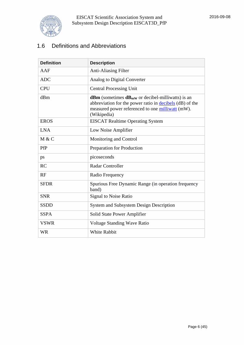
1.6 Definitions and Abbreviations
Definition Description
AAF Anti-Aliasing Filter
ADC Analog to Digital Converter
CPU Central Processing Unit
dBm dBm (sometimes dBmW or decibel-milliwatts) is an
abbreviation for the power ratio in decibels (dB) of the
measured power referenced to one milliwatt (mW).
(Wikipedia)
EROS EISCAT Realtime Operating System
LNA Low Noise Amplifier
M & C Monitoring and Control
PfP Preparation for Production
ps picoseconds
RC Radar Controller
RF Radio Frequency
SFDR Spurious Free Dynamic Range (in operation frequency
band)
SNR Signal to Noise Ratio
SSDD System and Subsystem Design Description
SSPA Solid State Power Amplifier
VSWR Voltage Standing Wave Ratio
WR White Rabbit

EISCAT Scientific Association System and
Subsystem Design Description EISCAT3D_PfP
2016-09-08
Page 7 (45)
2 References
The systems engineering work is based on the following documents:
Reference Title
[RCM] EISCAT_3D Radar Control and Monitoring
Subsystem Report
[NGTD] EISCAT_3D: The next generation
international atmosphere and geospace
research radar Technical Description
[Impl] Implementation of EISCAT_3D Test Sub-
Array Final Version June 2016
[MD] Milestone Document MC-1
Test sub-array sub-systems and interfaces.
[SysML] SysML Distilled
[WRS] White Rabbit Specification: version 2.0
[WRSw] White Rabbit Switch: User’s Manual wr-
switch-sw-v4.2

EISCAT Scientific Association System and
Subsystem Design Description EISCAT3D_PfP
2016-09-08
Page 8 (45)
3 System-wide design decisions
This chapter describes the requested behaviour of the Test Sub-array and the context
it will operate in, including both the actual physical environment as well as the
surrounding systems that the Test Sub-array needs to interact with in order to provide
its assigned technical functions.
3.1 Interactions with surrounding systems
The Test Sub-array will interact with a number of systems external to the Test Sub-
array. These interactions are displayed on the activity diagrams presented in chapter
Behavioural design.
The following diagram displays the surrounding systems the Test Sub-array will have
interfaces to.
Diagram 3: Operational domain
The diagram above shows the operational domain, i.e. the EISCAT_3D Test Sub-
array and its surrounding systems.
Antenna Calibration Tower
The Antenna Calibration Tower will be used during end-to-end calibration runs, and
will either transmit or receive the RF signals that are sent through the receive
chain/transmit chain of the Test Sub-array. Any offsets (unexpected time delays) that
ibd [block] Operational domain [Operational domain]
Tromsö sitep74
p75
p73
p82:
TBD
: EISCAT_3D
Test Sub-arrayp74
p75
p73
p82:
TBD
: Antenna
Calibration
Tower
cs: Computing
System
: EROS
: EROS Power
switch
: Mains Power
1
Gb/s

EISCAT Scientific Association System and
Subsystem Design Description EISCAT3D_PfP
2016-09-08
Page 9 (45)
are discovered through the calibration test will be used as input to the beamformer for
example. The behavioural context of the Test Sub-array’s interactions with the
Antenna Calibration Tower is displayed on the calibrate diagrams in section
"Subsystem interaction".
Computing System
The computing system will, during the PfP phase, consist of a computer used to store
and process the measurement data from the First Stage Beamformer.
EROS
EROS (EISCAT real-time operating system) is an M&C software system that also
serves as the user interface of the Test Sub-array. EROS monitors and controls the
different subsystems through its communication with the Subsystem Managers that
are included in the subsystems. The communication consists of the exchange of
simple text messages.
EROS sends status commands inquiring about the health of the subsystems and also
sends non-time-critical control commands, for example commands related to system
startup and shutdown. These commands then initiate some kind of predefined
behaviour, e.g. activities being carried out and/or information being returned. EROS
can also receive unprompted notifications from the Subsystem Manager if it detects
any anomalies.
EROS will be located inside the main building at the Tromsö site and will be accessed
through a wide area network (currently 100 Mb/s communication link using fibre
Ethernet) connecting the Test Sub-array site to the Tromsö University network. The
Slow Ethernet will use a small part of this faster network.
EROS Power switch
The EROS Power switch is a remotely controlled independent networked power
switch that allows EROS to reboot SubMan, the software running on the Subsystem
Manager computer, see section Subsystem Manager for more information.
Mains Power
The power supply to the Test Sub-array site.
3.2 Physical environment
The site for the Test Sub-array is located in Ramfjordmoen outside of Tromsö,
Norway. Its climate has to be taken into consideration (risk of snow accumulation, et
cetera) when designing the different subsystems, and the parts of the system that have
direct interfaces with the environment also need to be resilient to the kind of wildlife
that can be expected at the site.
EISCAT Scientific Association System and
Subsystem Design Description EISCAT3D_PfP
2016-09-08
Page 10 (45)
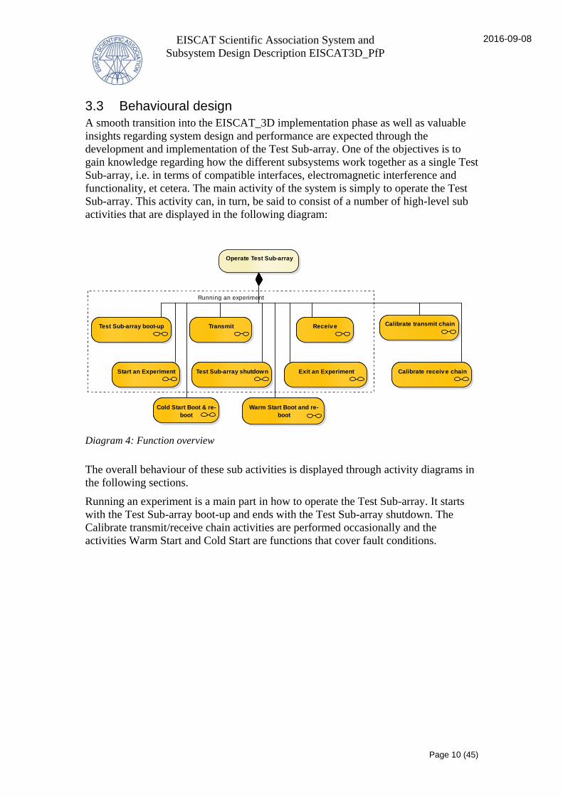
3.3 Behavioural design
A smooth transition into the EISCAT_3D implementation phase as well as valuable
insights regarding system design and performance are expected through the
development and implementation of the Test Sub-array. One of the objectives is to
gain knowledge regarding how the different subsystems work together as a single Test
Sub-array, i.e. in terms of compatible interfaces, electromagnetic interference and
functionality, et cetera. The main activity of the system is simply to operate the Test
Sub-array. This activity can, in turn, be said to consist of a number of high-level sub
activities that are displayed in the following diagram:
Diagram 4: Function overview
The overall behaviour of these sub activities is displayed through activity diagrams in
the following sections.
Running an experiment is a main part in how to operate the Test Sub-array. It starts
with the Test Sub-array boot-up and ends with the Test Sub-array shutdown. The
Calibrate transmit/receive chain activities are performed occasionally and the
activities Warm Start and Cold Start are functions that cover fault conditions.
Running an experiment
Operate Test Sub-array
Calibrate receiv e chainCalibrate receiv e chain
Receiv eReceiv e
Start an ExperimentStart an Experiment
Calibrate transmit chainCalibrate transmit chain
Cold Start Boot & re-
boot
Cold Start Boot & re-
boot
Test Sub-array shutdownTest Sub-array shutdown
TransmitTransmitTest Sub-array boot-upTest Sub-array boot-up
Exit an ExperimentExit an Experiment
Warm Start Boot and re-
boot
Warm Start Boot and re-
boot
EISCAT Scientific Association System and
Subsystem Design Description EISCAT3D_PfP
2016-09-08
Page 11 (45)
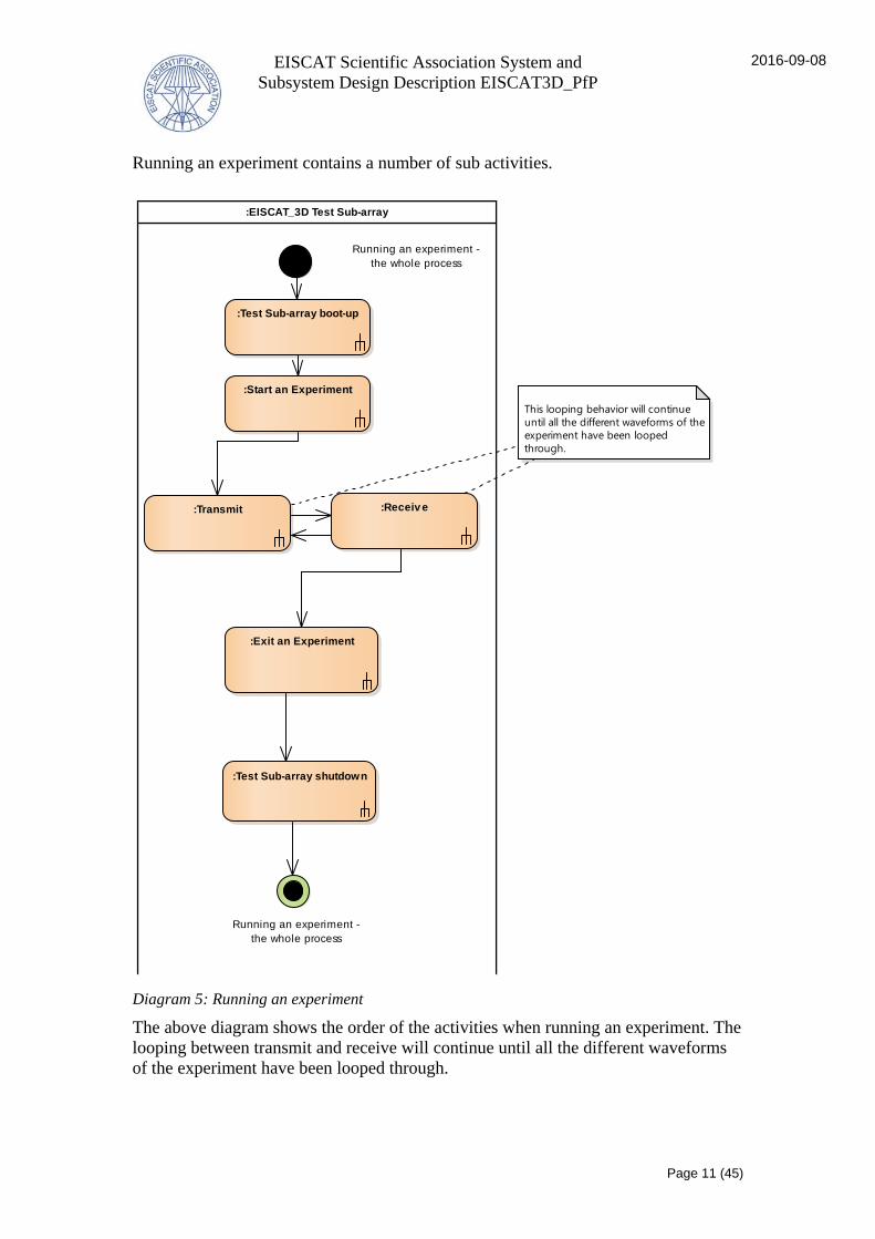
Running an experiment contains a number of sub activities.
Diagram 5: Running an experiment
The above diagram shows the order of the activities when running an experiment. The
looping between transmit and receive will continue until all the different waveforms
of the experiment have been looped through.
:EISCAT_3D Test Sub-array
:Transmit :Receiv e
:Start an Experiment
Running an experiment -
the whole process
Running an experiment -
the whole process
:Test Sub-array boot-up
:Test Sub-array shutdown
This looping behavior will continue
until all the different waveforms of the
experiment have been looped
through.
:Exit an Experiment

EISCAT Scientific Association System and
Subsystem Design Description EISCAT3D_PfP
2016-09-08
Page 12 (45)
3.3.1 Test Sub-array boot-up
The activity describes what, and which subsystems, is involved in the process of
booting up the Test Sub-array.
Diagram 6: Test Sub-array boot-up
The Test Sub-array is booted-up through the EROS M&C system, which sends boot-
up commands to the Test Sub-array subsystems. The subsystems (through the control
of the Subsystem Managers) will then perform the necessary boot-up tasks, and
finally send back a message to EROS stating that the subsystem is booted-up.
act [Function] Test Sub-array boot-up [Test Sub-array boot-up]
:First Stage Receiv er Unit:Transmit Unit:Time and Frequency Unit:Pulse and Steering Control
Unit
:EROS
:Test Sub-array
boot-up process
initiated
:Send subsystem
boot-up
commands
:Boot up :Boot up :Boot up :Boot up
:Subsystem
booted-up signal
:Subsystem
booted-up signal
:Subsystem
booted-up signal
:Subsystem
booted-up signal
:Starting the
experiment

EISCAT Scientific Association System and
Subsystem Design Description EISCAT3D_PfP
2016-09-08
Page 13 (45)
3.3.2 Start an Experiment
The activity describes what, and which subsystems, is involved in the process of
starting a Test Sub-array experiment.
Diagram 7: Start an Experiment
An experiment is initiated by EROS. EROS primes the radar function subsystems,
which then performs (through the Subsystem Managers) the system start-up tasks.
The Start an Experiment activity ends after the radar subsystems have sent
"subsystem prepared" signals to EROS. The Time and Frequency Unit is also
continuously distributing the time & synchronization to the PSCU and the FSRU.
:Transmit Unit:First Stage Receiv er Unit:Pulse and Steering Control Unit:Time and Frequency Unit:EROS
:Create and Send
Test Sub-array
start-up signal
:Initialize streaming of
priming commands
:Perform system
start-up tasks
:Receiv e priming
commands
:Receiv e time
:Generate and
distribute time &
synch
Note that this reflects the simplified flow
and hence some tasks and/or flows have
been omitted from this diagram
:Receiv e priming
commands
:Receiv e time
:Receiv e priming
commands
Continuous flow :Send subsystem
prepared signal:Send subsystem
prepared signal:Send subsystem
prepared signal
Activity final
ActivityInitial
:Perform system
start-up tasks
:Perform system
start-up tasks

EISCAT Scientific Association System and
Subsystem Design Description EISCAT3D_PfP
2016-09-08
Page 14 (45)
3.3.3 Transmit
The activity describes what, and which subsystems, is involved in the Test Sub-array
transmit process.
Diagram 8: Transmit
A Transmit session starts by executing the next line of the event lists provided by the
Subunit Controller. The PSCU calculates new waveforms based on delays and
amplitudes for each channel, generates the proper RF signals that are then up-
converted and analogized before being sent off to the Transmit Unit for amplification
and then to the Antenna Unit which emits the radio frequency waves.
act [Function] Transmit [Transmit]
:Antenna Unit:Pulse and Steering Control Unit :Transmit Unit
:Carry out next line of ev ent list
:Send RF signals
:Calculate new wav eforms,
generate RF signals,
upconv ert & analogize
:Switch to
transmit mode
:Receiv e
generated RF
signals
:Amplify and send
RF signals:Transmit RF
signals
Subsystems have
been primed by
EROSNote that looping occurs until all the scheduled
transmission waveforms have been looped
through. The behavior displayed on this diagram
is simplified and does not explicitly describe for
example transitions to the receive state and
reception of transmission sample.
:Generate & send
T/R control
signals
EISCAT Scientific Association System and
Subsystem Design Description EISCAT3D_PfP
2016-09-08
Page 15 (45)
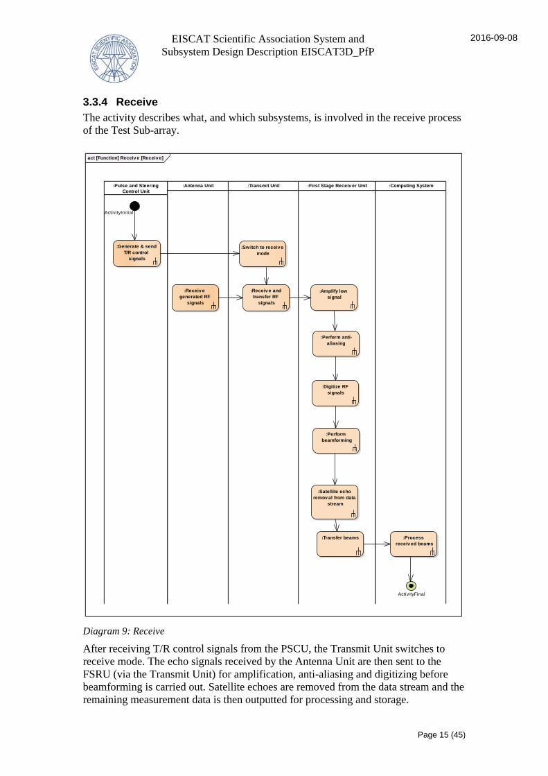
3.3.4 Receive
The activity describes what, and which subsystems, is involved in the receive process
of the Test Sub-array.
Diagram 9: Receive
After receiving T/R control signals from the PSCU, the Transmit Unit switches to
receive mode. The echo signals received by the Antenna Unit are then sent to the
FSRU (via the Transmit Unit) for amplification, anti-aliasing and digitizing before
beamforming is carried out. Satellite echoes are removed from the data stream and the
remaining measurement data is then outputted for processing and storage.
act [Function] Receiv e [Receiv e]
:Pulse and Steering
Control Unit
:First Stage Receiv er Unit:Transmit Unit:Antenna Unit
:Receiv e and
transfer RF
signals
:Receiv e
generated RF
signals
:Amplify low
signal
:Switch to receiv e
mode
:Perform anti-
aliasing
:Perform
beamforming
:Transfer beams
:Digitize RF
signals
:Process
receiv ed beams
:Satellite echo
remov al from data
stream
ActivityInitial
:Computing System
ActivityFinal
:Generate & send
T/R control
signals

EISCAT Scientific Association System and
Subsystem Design Description EISCAT3D_PfP
2016-09-08
Page 16 (45)
3.3.5 Exit an Experiment
The activity describes what, and which subsystems, is involved in exiting an
experiment.
Diagram 10: Exit an Experiment
After receiving an exit signal from EROS, the subsystems perform (through the
Subsystem Managers) the different tasks needed to exit the active experiment mode.
Finally, the Subsystem Managers of the subsystems send messages to EROS stating
the experiment exit process has been completed.
:Transmit Unit:First Stage Receiv er
Unit
:Pulse and Steering
Control Unit
:EROS
:Create and Send
Test Sub-array
exit signal
:Send subsystem
exited signal
:Send subsystem
exited signal:Send subsystem
exited signal
:Perform system
exit tasks
:Perform system
exit tasks
:Perform system
exit tasks
ActivityFinal

EISCAT Scientific Association System and
Subsystem Design Description EISCAT3D_PfP
2016-09-08
Page 17 (45)
3.3.6 Test Sub-array shutdown
The activity describes what, and which subsystems, is involved in shutting down the
Test Sub-array.
Diagram 12: Test Sub-array shutdown
The shutdown process is initialized by EROS which then commands the Subsystem
Managers (except for the Time and Frequency Unit where this communication is
made directly to the system) of the subsystems to perform the procedures necessary to
shut down the subsystem.
:First Stage Receiv er Unit:Transmit Unit:Time and Frequency Unit:Pulse and Steering Control
Unit
:EROS
:Test Sub-array
shut-down
process initiated
:Subsystem
Shutdown
:Subsystem
Shutdown
:Subsystem
Shutdown
:Subsystem
Shutdown
:Send subsystem
shut-down
commands

EISCAT Scientific Association System and
Subsystem Design Description EISCAT3D_PfP
2016-09-08
Page 18 (45)
3.3.7 Calibrate transmit chain
The activity describes what, and which subsystems, is involved in the process of
calibrating the transmit chain of the Test Sub-array.
Diagram 11: Calibrate transmit chain
The process of calibrating the transmit chain runs through the system as it would
during normal transmit mode except the Transmit Unit sends the non-amplified
calibration signals to the Antenna Calibration Tower.
UserComputing system?:Antenna Calibration Tower:Pulse and Steering Control Unit :Transmit Unit
:Carry out next line of
ev ent list
:Send RF signals
:Receiv e
calibration signal
:Receiv e
generated RF
signals
:Insert new
settings
:Sav e and
process
calibration data
:Switch to
transmit mode
:Apply new settings
The settings are applied
to the exciter, but how
this is done is TBD.
ActivityInitial
:Generate & send
T/R control
signals
:Calculate new wav eforms,
generate RF signals,
upconv ert & analogize

EISCAT Scientific Association System and
Subsystem Design Description EISCAT3D_PfP
2016-09-08
Page 19 (45)
3.3.8 Calibrate receive chain
The activity describes what, and which subsystems, is involved in the process of
calibrating the receive chain of the Test Sub-array.
Diagram 13: Calibrate receive chain
The process of calibrating the receive chain runs through the system as it would
during normal receive mode. except the Antenna Calibration Tower starts the process
through sending out calibration Tx signals. After going through the different
processes of the receiver (no beamforming is performed), the calibration signals are
processed and offsets are calculated. The new settings are then manually inserted into
the First Stage Beamformer.
act [Function] Calibrate receiv e chain [Calibrate receiv e chain]
:User:Computing System:First Stage Receiv er
Unit
:Antenna Calibration Tower
:Prepare
calibration tx
:Amplify low
signal
:Perform anti-
aliasing
:Digitize RF
signals
:Calculate offsets
etc
:Process
calibration
signals
Note that this reflects the
simplified flow and hence some
tasks and/or flows have been
omitted from this diagram
:Insert new
settings into the
Beamformer
:Receiv e
calibration
signals
:Implement new
settings
ActivityInitial
ActivityFinal

EISCAT Scientific Association System and
Subsystem Design Description EISCAT3D_PfP
2016-09-08
Page 20 (45)
3.3.9 Warm Start Boot and re-boot
The activity describes what, and which subsystems, is involved in the process of
booting and re-booting the Test Sub-array during a “warm start” where SubMan is
still running and can respect an exit command from EROS.
Diagram 14: Warm Start Boot and re-boot
EROS sends an exit command to the SubMan of the Subsystem Manager. If SubMan
is responding it exits, following which the Subsystem Manager computer restarts
SubMan. In the case SubMan is not responding to the EROS exit command, EROS
terminates the process through a kill commands which shuts down SubMan, which in
turns leads to SubMan restarting.
act [Function] Warm Start Boot and re-boot [Warm Start Boot and re-boot]
Computer SubMan:EROS
Send exit
command
SubMan exitsComputer
restarts SubMan
is SubMan responding to exit command?
Terminate
process through
kill command
Shut down
SubManSubMan restarts
no
yes
EISCAT Scientific Association System and
Subsystem Design Description EISCAT3D_PfP
2016-09-08
Page 21 (45)
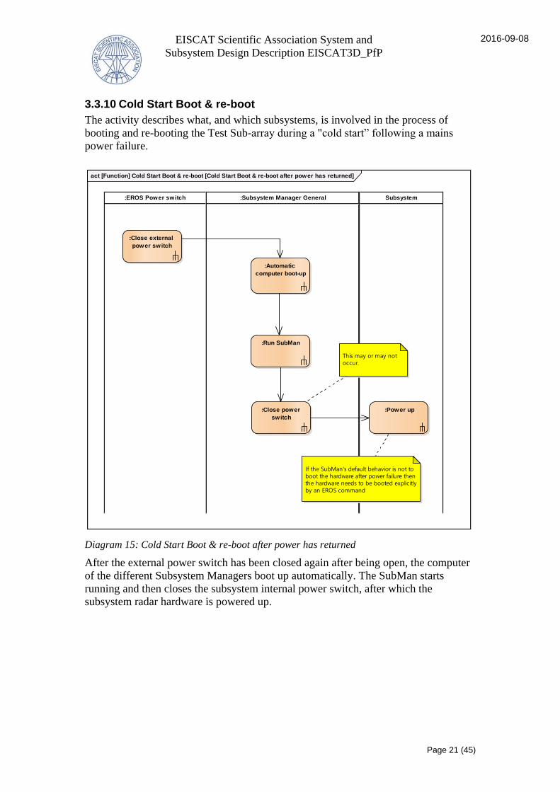
3.3.10 Cold Start Boot & re-boot
The activity describes what, and which subsystems, is involved in the process of
booting and re-booting the Test Sub-array during a "cold start” following a mains
power failure.
Diagram 15: Cold Start Boot & re-boot after power has returned
After the external power switch has been closed again after being open, the computer
of the different Subsystem Managers boot up automatically. The SubMan starts
running and then closes the subsystem internal power switch, after which the
subsystem radar hardware is powered up.
act [Function] Cold Start Boot & re-boot [Cold Start Boot & re-boot after power has returned]
:EROS Power switch Subsystem:Subsystem Manager General
:Close external
power switch
:Automatic
computer boot-up
:Run SubMan
:Power up
This may or may not
occur.
:Close power
switch
If the SubMan's default behavior is not to
boot the hardware after power failure then
the hardware needs to be booted explicitly
by an EROS command

EISCAT Scientific Association System and
Subsystem Design Description EISCAT3D_PfP
2016-09-08
Page 22 (45)
3.4 Overall design decisions
Due to its nature, some of the subsystems of the Test Sub-array will have to be RF
shielded in order to protect them from the radiated fields in the array, as well as the
internally generated RF noise (e.g. clock signals). The following overall design
decisions have been taken to address this:
The Test Sub-array will contain two RF shielded instrument containers – one for
the Transmit System and one housing the First Stage Receiver Unit, the Pulse and
Steering Control Unit, and the Time and Frequency Unit. This solution will shield
the sensitive subsystems by preventing direct electromagnetic interference to these
from the Transmit Unit.
The design of the internal electronics will also include protection from internally
generated electromagnetic noise within the Test Sub-array

EISCAT Scientific Association System and
Subsystem Design Description EISCAT3D_PfP
2016-09-08
Page 23 (45)
4 System architectural design
This chapter describes the technical system that enables the behaviour described in
section Behavioural design. The Test Sub-array consists of a number of subsystems
and these components are defined and described in this chapter.
This chapter displays a number of structural diagrams of the Test Sub-array and its
subsystems. See section 6.1 Description of Diagrams for more information.
4.1 System components
The following diagram displays an overview of the technical subsystems of the Test
Sub-array. The arrowed lines represent the categories of interactions that have been
identified between the subsystems. A category (e.g. status, notifications and RF) can
comprise a number of different signals or information flows. The external systems
that the Test Sub-array are interacting with are represented by the ports on the edge of
the diagram. For a more comprehensive view this diagram can be read together with
the "Operational Domain" diagram. Note that the diagram provides a simplified view,
thus all parts and components of the subsystems may not be visualized.
The Test Sub-array is a phased-array antenna radar system containing 91 crossed
dipole antenna elements, a beamformer, a receiver, a transmitter and other subsystems
for control, time-keeping et cetera.
Diagram 16: Test Sub-array Technical systems High level Overview
The diagram above displays a high level overview of the technical subsystems of the
Test Sub-array. It conveys not only which components interact with each other, but
also the kind of information that is exchanged between the components.
ibd [block] EISCAT_3D Test Sub-array [Test Sub-array Technical systems High lev el Ov erv iew]
pscu / d: Pulse and Steering Control Unit
tu / c: Transmit Unit
fsru / e: First Stage Receiv er Unit
tfu / b: Time and Frequency Unitau / a: Antenna Unit
Tx
Rx
Rx, Tx
signals EROS control, Status inquiry Notification, Status
EROS control,
Status inquiry
Notification,
Status
Tx
EROS control,
Status inquiry
Notification,
Status
T/R Control
Measurement data
Status inquiry,
EROS control
Notification,
Status
Time,
Synchronization

EISCAT Scientific Association System and
Subsystem Design Description EISCAT3D_PfP
2016-09-08
Page 24 (45)
4.1.1 General components
The section describes general components found in the EISCAT_3D Test Sub-array.
4.1.1.1 Subsystem Manager
EISCAT_3D Test Sub-array contains several different subsystem managers which are
named "Subsystem Manager Xyz". Each different subsystem manager has a specific
set of behaviors and functionality that is described in its corresponding section. The
description, behavior and functionality below is general for all subsystem managers
and is defined by the Subsystem Manager. Note that the Subsystem Manager is not a
real physical component itself but just a placeholder for a general description. A
Subsystem Manager communicates through “SubMan”.
The Subsystem Manager provides a network-accessible interface between its
associated subsystem (a block of hardware with basic software and firmware that
implements a set of specific radar functionality) and EROS. The Subsystem Manager
implements SubMan that EROS communicates with in order to control and monitor
the subsystem. This is enabled by the Subsystem Manager providing a TCP socket
listener at a fixed (but configurable) network address.
SubMan receives EROS control commands that specify what the subsystem is
expected to do and SubMan also receives Status inquiry commands that specify
specific information that EROS needs SubMan to return in the form of a Status
message. SubMan also issues Notifications to EROS, without being explicitly
prompted by EROS, if it detects an anomaly of some kind, e.g. if some predefined
conditions are met (e.g. temperature exceeding a set maximum value).
4.1.1.2 Subunit Controller
The Subunit Controller supplements the overall architecture with binary packets
containing waveforms and event lists needed for the PSCU. Event lists include time
stamps, waveform start time, and state changes for T&R switch and extra outputs.

EISCAT Scientific Association System and
Subsystem Design Description EISCAT3D_PfP
2016-09-08
Page 25 (45)
4.1.2 Pulse and Steering Control Unit
The Test Sub-array subsystems are able to operate together as intended through
different control pulses or triggers that determine when the different subsystems begin
their different tasks. The Pulse and Steering Control Unit, together with external
system Subunit Controller (see section Subunit Controller for more information),
provides this control capability in addition to generating and distributing the actual RF
signals.
Diagram 17: Pulse and Steering Control Unit
The diagram above displays the logical implementation of the PSCU components.
Actual implementation is up to the vendor. The main functions of the PSCU is to
produce and send control commands to the Transmit Unit T/R Switch, calculate and
send waveforms for each channel that take given delays and amplitudes into
consideration as well.
Also displayed on the diagram is the Subunit Controller, which is not part of the
procurement object PSCU (hence dashed border) but is closely connected to it and
displayed for comprehension purposes.
p10: Mechanical and
Electrical Interface
p11:
GPIO
p08: RF
[192]
p09: Slow
Ethernet
ibd [block] Pulse and Steering Control Unit [Pulse and Steering Control Unit]
p10: Mechanical and
Electrical Interface
p11:
GPIO
p08: RF
[192]
p09: Slow
Ethernet
Port1: TCP
Port2: UDP
sm: Subsystem Manager PSCU[1]
Port1: TCP
Port2: UDP
e: Exciter[1..*]
ps: Power Supply PSCU
[1..*]
wrs: WR Slav e PSCU
[1]
suc: Subunit
Controller
there will be 182 (91x2) RF signals and 10 extra
channels for calibration purposes. The number
of physical exciter units is up to the vendor.
1 output for T/R control and 7 extra
outputs for oscillators et cetera.
fc: 233.3 MHzTime,
Synchronization
T/R Control,
General SignalsStatus, Notification External Control,
Status inquiry
Event l ists,
Waveforms
230 V
Time,
Synchronization

EISCAT Scientific Association System and
Subsystem Design Description EISCAT3D_PfP
2016-09-08
Page 26 (45)
4.1.2.1 Subsystem
Exciter
The Exciter generates RF signals that will be up converted and analogized before
distributed to the Transmit Unit for amplification. The signals include all information
about the frequency, phase and polarization. The Exciter also includes a T/R control
function which generates and sends control signals to the Transmit Unit T/R Switch.
The Exciter is time synchronized through the WR system.
Power Supply PSCU
The Power Supply PSCU is supplied 230 V (AC) from the site mains power.
Subsystem Manager PSCU
The Subsystem Manager PSCU is specific for the Pulse and Steering Control Unit.
The Subsystem Manager provides slow control input, mainly during system start-up,
and system status monitoring. The specific functionality of the Subsystem Manager
PSCU includes the calculation of new waveforms based on given delay and amplitude
values for each channel and implementing a buffer for event lists provided by the
Subunit Controller.
WR Slave PSCU
The WR Slave extracts the time and synchronization from the 1 Gb Ethernet network
and provides it to the subsystem. The WR Slave consists of specialized WR node
cards.
4.1.2.2 Informationflows
Name Information Producer Interface Consumer Interface
c070 Waveforms,
Event lists
suc N/A sm Port2:UDP
c071 Notification,
Status
sm Port1:TCP suc N/A
c071 External
Control, Status
inquiry
suc N/A sm Port1:TCP
c13 fc: 233.3 MHz
e N/A Pulse and
Steering
Control Unit
p08:RF
c16 230 V
Pulse and
Steering
Control Unit
p10:Mechani
cal and
Electrical
Interface
ps N/A

EISCAT Scientific Association System and
Subsystem Design Description EISCAT3D_PfP
2016-09-08
Page 27 (45)
Name Information Producer Interface Consumer Interface
c704 T/R Control,
General Signals
e N/A Pulse and
Steering
Control Unit
p11:GPIO
c705 Time,
Synchronizatio
n
Pulse and
Steering
Control Unit
p09:Slow
Ethernet
wrs N/A
4.1.2.3 Interfaces
Name Type Information
p08 RF The radio frequency signals from the Exciter to the
Transmit Unit are sent over this interface.
p09 Slow Ethernet The communication with EROS is sent over this
interface.
p10 Mechanical and
Electrical
Interface
This interface provides the Pulse and Steering Control
Unit with the required current and voltage. It also
includes the physical interface.
p11 GPIO The T/R control signals and General Signals to the
Transmit Unit are sent over this interface.
4.1.3 Network Components
Network Components are TBD.

EISCAT Scientific Association System and
Subsystem Design Description EISCAT3D_PfP
2016-09-08
Page 28 (45)
4.1.4 Antenna Unit
The Antenna Unit includes the subsystems Antenna Array, Array Structure and
Ground Plane. Note that the unit also includes mechanical attachment interfaces as
well as cables, connectors and cable trays (or similar).
Diagram 18: Antenna Unit
The diagram displays the Antenna Unit and all of its parts. As shown on the diagram,
the Antenna Unit also includes an Array Structure which the Antenna Elements are
mounted on, and a meshed ground plane which is attached to the Array Structure.
Further, the Antenna Unit also includes the cables and connectors that connects the
Antenna Unit to the Transmit Unit. The antenna cables are routed to a point near the
center of the Test Sub-array just below the Array Structure.
4.1.4.1 Subsystem
Antenna Array
The Antenna Array consists of the Antenna Elements.
The purpose of the Antenna Array of the Test Sub-array is to transduce the RF signals
to electromagnetic waves (or vice versa if in receive mode). The hexagonally shaped
array will consist of 91 crossed-dipole Antenna Elements, hence adding up to a total
number of 182 dipoles to be sampled. The dipoles are tilted back towards the ground
plane (inverted v-shape) to enable good steering without excessive changes in
polarization ratio or antenna terminal impedance.
The antenna elements of the Antenna Array are mounted on a support structure
described in section Array Structure.
p98:
Mechanical
Attachment
Interface
p97:
RF
ibd [block] Antenna Unit [Antenna Unit]
p98:
Mechanical
Attachment
Interface
p97:
RF
p94:
Mechanical
Attachment
Interface
: Array Structure
p94:
Mechanical
Attachment
Interface
: Ground Plane
p01: RF
: Antenna Array
p01: RF
ae: Antenna Element
[91]

EISCAT Scientific Association System and
Subsystem Design Description EISCAT3D_PfP
2016-09-08
Page 29 (45)
Antenna Unit Cables and Connectors
The Antenna Unit Cables and Connectors are all the cables and connectors used to
connect the antennas to the Transmit Unit.
Array Structure
The Array Structure is a metallic support structure holding all the Antenna Elements.
The Array Structure is approximately 3 meters high.
Ground Plane
The Ground Plane is a flat, or nearly flat, horizontal conducting surface that serves as
part of an antenna, to reflect the radio waves from the other antenna elements.
4.1.4.2 Interfaces
Name Type Information
p97 RF Interface for radio frequency signals between the
Antenna Unit and the Transmit Unit.
p98 Mechanical
Attachment
Interface
Interface between Array Structure and foundation.
EISCAT Scientific Association System and
Subsystem Design Description EISCAT3D_PfP
2016-09-08
Page 30 (45)
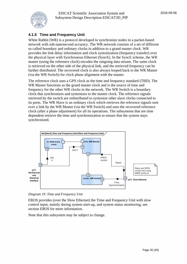
4.1.5 Time and Frequency Unit
White Rabbit (WR) is a protocol developed to synchronize nodes in a packet-based
network with sub-nanosecond accuracy. The WR network consists of a set of different
so called boundary and ordinary clocks in addition to a grand master clock. WR
provides the link delay information and clock syntonization (frequency transfer) over
the physical layer with Synchronous Ethernet (SyncE). In the SyncE scheme, the WR
master (using the reference clock) encodes the outgoing data stream. The same clock
is retrieved on the other side of the physical link, and the retrieved frequency can be
further distributed. The recovered clock is also always looped back to the WR Master
(via the WR Switch) for clock phase alignment with the master.
The reference clock uses a GPS clock as the time and frequency standard (TBD). The
WR Master functions as the grand master clock and is the source of time and
frequency for the other WR clocks in the network. The WR Switch is a boundary
clock that synchronizes and syntonizes to the master clock. The reference signals
retrieved by the switch are redistributed to syntonize other slave clocks connected to
its ports. The WR Slave is an ordinary clock which retrieves the reference signals sent
over a link by the WR Master (via the WR Switch) and uses the recovered reference
clock (after a phase adjustment) for all its operations. The subsystems that are time
dependent retrieve the time and synchronization to ensure that the system stays
synchronized.
Diagram 19: Time and Frequency Unit
EROS provides (over the Slow Ethernet) the Time and Frequency Unit with slow
control input, mainly during system start-up, and system status monitoring, see
section EROS for more information.
Note that this subsystem may be subject to change.
p17:
Mechanical
and
Electrical
Interfacep47: Slow Ethernet
ibd [block] Time and Frequency Unit [Time and Frequency Unit]
p17:
Mechanical
and
Electrical
Interfacep47: Slow Ethernet
wrm: WR Masterrc: Reference
clock
wrsw: WR Switch
Status and EROS
control sent using
SNMP protocol
230 V
230
V
EROS
control
Status
Time,
Synchronization
EISCAT Scientific Association System and
Subsystem Design Description EISCAT3D_PfP
2016-09-08
Page 31 (45)
4.1.5.1 Subsystem
Reference clock
The reference clock uses a GPS clock as the time and frequency standard, and
provides a reference phase for the transmitted and received signals.
WR Master
The WR Master uses a traceable clock to encode data over SyncE.
WR Switch
The WR Switch then distributes the clock signal over a 1 Gbit/s Ethernet network (the
same network will also be used for inputs and outputs of the EROS).
4.1.5.2 Informationflows
Name Information Producer Interface Consumer Interface
c1847 Status
wrm p18:Slow
Ethernet
Time and
Frequency
Unit
p47:Slow
Ethernet
c1847 EROS control
Time and
Frequency
Unit
p47:Slow
Ethernet
wrm p18:Slow
Ethernet
c28 230 V
Time and
Frequency
Unit
p17:Mechani
cal and
Electrical
Interface
rc p45:Mechani
cal and
Electrical
Interface
c32 230 V
Time and
Frequency
Unit
p17:Mechani
cal and
Electrical
Interface
wrm p26:Mechani
cal and
Electrical
Interface
c44 Time,
Synchronizatio
n
wrsw p21:Slow
Ethernet
Time and
Frequency
Unit
p47:Slow
Ethernet
4.1.5.3 Interfaces
Name Type Information
p17 Mechanical and
Electrical
Interface
Interface providing the Time and Frequency Unit with
power. Ihe interface connects to the power supply.
p47 Slow Ethernet WR time

EISCAT Scientific Association System and
Subsystem Design Description EISCAT3D_PfP
2016-09-08
Page 32 (45)
4.1.6 Cables and Connectors
The Test Sub-array also includes the Cables and Connectors necessary to connect the
different subsystems. The system component includes:
the technical solution to send the Radar control signals throughout the system
the technical solution to send the Interlock control signals throughout the system
Note that the cables and connectors for the Antenna Elements are included in the
Antenna Unit as described in section Antenna Unit.
4.1.7 Transmit unit container
The Transmit Unit Container is container containing equipment for the transmit unit.
Diagram 20: Transmit unit container
The diagram shows the Transmit Unit Container and its external interfaces. The
container contains the Transmit Unit.
4.1.7.1 Interfaces
Name Type Information
1 Gb Slow Ethernet 1 Gb Ethernet interface.
3-phase Mechanical and
Electrical
Interface
400 volts interface.
RF from
exciter(s)
RF From Pulse and Steering Control.
Rx and
Tx signals
RF Interface for Tx and Tx signals to the First Stage
Receive Unit.
RF from exciter
(s): RF
T/R Control:
GPIO
1 Gb: Slow
Ethernet
Rx and Tx
signals: RF
3-phase:
Mechanical and
Electrical Interface
Tx and Rx: RF
ibd [block] Transmit unit container [Transmit unit container]
RF from exciter
(s): RF
T/R Control:
GPIO
1 Gb: Slow
Ethernet
Rx and Tx
signals: RF
3-phase:
Mechanical and
Electrical Interface
Tx and Rx: RFtu: Transmit Unit

EISCAT Scientific Association System and
Subsystem Design Description EISCAT3D_PfP
2016-09-08
Page 33 (45)
Name Type Information
T/R
Control
GPIO Interface for control signals from the Pulse and
Steering Control Unit.
Tx and
Rx
RF From Antenna Unit
4.1.8 Climate monitoring equipment
This unit will monitor the temperature and humidity inside the Instrument Container
described in section Instrument Containers, and will send this information to the
container Subsystem Manager.
4.1.8.1 Interfaces
Name Type Information
p49 TBD
p50 TBD
4.1.9 TU Power Supply Container
The TU Power Supply Container contains the power supply for the Transmit unit.
4.1.10 Subsystem Manager Container
The Subsystem Manager Container is specific for the Instrument Container. The
specific functionality is to be defined.
4.1.10.1 Interfaces
Name Type Information
p104 Mechanical and
Electrical
Interface
p65 TCP First Stage Receiver Unit
p68 TBD First Stage Receiver Unit
p88 Listening TCP
socket
4.1.11 Transmit Unit
The main purpose of the Transmit Unit is to produce high-power RF pulses that are
radiated into space by the Antenna Elements. The subsystem consists of power
amplifiers, T/R switches, power supply units and a Subsystem Manager (see EROS in
section Interactions with surrounding systems and section Subsystem Manager for
more information).
The power amplifiers are used to amplify the RF waveform for transmission and the
SSPA is a power amplifier that supports long pulses and high duty cycle waveforms.
The T/R Switch shifts the radar system from transmit mode (when the Transmit Unit
needs to be connected to the Antenna Unit and disconnected from the receiver) to

EISCAT Scientific Association System and
Subsystem Design Description EISCAT3D_PfP
2016-09-08
Page 34 (45)
receive mode (when the T/R Switch will connect the incoming RF signals to the
receiver) or vice versa.
The following diagram displays the Transmit Unit, its parts, and its external
interfaces.
Diagram 21: Transmit Unit
The diagram displays all external interfaces. When the subsystem is in transmitting
mode, the RF signal from the Pulse and Steering Control Unit is received by the
SSPA unit. After amplification the RF signal is sent to the Antenna Elements via the
T/R Switch and a, much attenuated, copy of the RF signal is also sent to the Front End
of the First Stage Receiver Unit. During receive mode the incoming RF signal is
received by the First Stage Receiver Unit via the T/R Switch.
4.1.11.1 Subsystem
SSPA Unit
The SSPA Unit contains the T/R Switch, and is installed and operated inside the
container below the support structure for the antenna sub-array. The SSPA also
contains supervisor functions for output power, excess reflected power, excess
temperature, and other critical parameters.
p32:
RF
p28: Slow Ethernetp29: Mechanical and Electrical
Interface
p31:
RF
p30:
GPIO
p27:
RF
p107
ibd [block] Transmit Unit [Transmit Unit]
p32:
RF
p28: Slow Ethernetp29: Mechanical and Electrical
Interface
p31:
RF
p30:
GPIO
p27:
RF
p107
p40
p41
p42sm tu: Subsystem
Manager TU
p40
p41
p42
p38
p43p44
ps: Power supply TU
p38
p43p44
p33
p36
p37
p99
su: SSPA Unit
p33
p36
p37
p99
s1: SSPA[182] trs: T/R Switch[182]
fc: 233.3 MHz
T/R
Control
400 VStatus,
Notification
Status inquiry,
EROS control
fc: 233.3 MHz
fc: 233.3 MHz
Interlock control
Status
SubMan control
182 182
182 182
182
182

EISCAT Scientific Association System and
Subsystem Design Description EISCAT3D_PfP
2016-09-08
Page 35 (45)
4.1.11.2 Informationflows
Name Information Producer Interface Consumer Interface
c10799 Interlock
control
Transmit
Unit
p107 su p99:Interlock
control
c35 fc: 233.3 MHz
Transmit
Unit
p27:RF su p36:TBD
c37 Notification,
Status
sm tu p41:Slow
Ethernet
Transmit
Unit
p28:Slow
Ethernet
c37 Status inquiry,
EROS control
Transmit
Unit
p28:Slow
Ethernet
sm tu p41:Slow
Ethernet
c38 400 V
Transmit
Unit
p29:Mechani
cal and
Electrical
Interface
ps p43:Mechani
cal and
Electrical
Interface
c42 fc: 233.3 MHz
su p35:TBD Transmit
Unit
p31:RF
c43 fc: 233.3 MHz
Transmit
Unit
p32:RF su p34:TBD
c43 fc: 233.3 MHz
su p34:TBD Transmit
Unit
p32:RF
4.1.11.3 Interfaces
Name Type Information
p107 TBD Interface for Interlock Control Signals. TBD.
p27 RF Interface for incoming radio frequency signals from
the Exciter of the Pulse and Steering Control Unit.
p28 Slow Ethernet Interface for information exchange with M&C system
external to the Test Sub-array.
p29 Mechanical and
Electrical Interface
400 V, 3 phase
p30 GPIO The interface block handles T/R Control and is TBD.
p31 RF Interface for radio frequency signals between the
Transmit Unit and the First Stage Receiver Unit.
p32 RF Interface for radio frequency signals between the
Antenna Unit and the Transmit Unit.

EISCAT Scientific Association System and
Subsystem Design Description EISCAT3D_PfP
2016-09-08
Page 36 (45)
4.1.12 Instrument Container
Some of the sensitive systems and equipment are placed in an instrument container to
aid with temperature and humidity control and RF shielding (to protect the internal
electronics). Environmental and power monitoring equipment will also be placed in
the container to enable remote monitoring and control. The electrical systems located
inside the container will also include remote control capabilities to for example allow
powering down failed or interfering units. Maintenance and cost are two major factors
that will affect the design of the internal layout of the container. The Transmit Unit is
placed in its own container in order to meet the requirements described in section 3.4
Overall design decisions. To monitor the state of the Instrument Container, it will
house its own Subsystem Manager.
The following diagram displays the Instrument Container and the subsystems located
inside of it. The rectangles representing the technical subsystems are dashed to reflect
that they are not parts of the Instrument Container.
Diagram 22: The Instrument Container including the systems and components it is housing
The above diagram displays the instrument container and the subsystems located
inside of it. The rectangles representing the technical subsystems are dashed to reflect
that they are not parts of the instrument container.
4.1.12.1 Interfaces
Name Type Information
p101 RF The RF signals to, and from, the Transmit Unit and
sent over this interface.
p102 GPIO The control signals to the Transmit Unit are sent over
this interface.
p103 Slow Ethernet The time and synchronization from the Time and
Frequency Unit as well as the EROS communication
is sent over this interface.
p105: Fast
Ethernet
p103: Slow Ethernet
p106: TBD
p102: GPIO
p51: Mechanical
Attachment Interface
p53: Mechanical and
Electrical Interface
p101: RF
ibd [block] Instrument Container [The Instrument Container including the systems and components it is housing]
p105: Fast
Ethernet
p103: Slow Ethernet
p106: TBD
p102: GPIO
p51: Mechanical
Attachment Interface
p53: Mechanical and
Electrical Interface
p101: RF
p07p03
p04p05
fsru: First Stage Receiv er Unit
p07p03
p04p05
p08[192]
p11
p09p10
pscu: Pulse and Steering Control Unit
p08[192]
p11
p09p10
p47
p17
tfu: Time and Frequency Unit
p47
p17
p68
p65 p88 p104
sm: Subsystem Manager Container
p68
p65 p88 p104
: Computing System
EISCAT Scientific Association System and
Subsystem Design Description EISCAT3D_PfP
2016-09-08
Page 37 (45)
Name Type Information
p105 Fast Ethernet The measurement data from the computing system is
sent over this interface.
p106 TBD This interface is for the RF (Tx and Rx) signals from
the Transmit Unit.
p51 Mechanical
Attachment
Interface
This interface attaches the different subsystems within
the Instrument Container.
p53 Mechanical and
Electrical
Interface
The mechanical and electrical interface provides the
component with the required voltage and current.
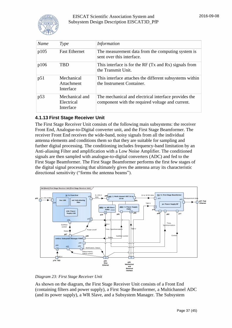
4.1.13 First Stage Receiver Unit
The First Stage Receiver Unit consists of the following main subsystems: the receiver
Front End, Analogue-to-Digital converter unit, and the First Stage Beamformer. The
receiver Front End receives the wide-band, noisy signals from all the individual
antenna elements and conditions them so that they are suitable for sampling and
further digital processing. The conditioning includes frequency-band limitation by an
Anti-aliasing Filter and amplification with a Low Noise Amplifier. The conditioned
signals are then sampled with analogue-to-digital converters (ADC) and fed to the
First Stage Beamformer. The First Stage Beamformer performs the first few stages of
the digital signal processing that ultimately gives the antenna array its characteristic
directional sensitivity (“forms the antenna beams”).
Diagram 23: First Stage Receiver Unit
As shown on the diagram, the First Stage Receiver Unit consists of a Front End
(containing filters and power supply), a First Stage Beamformer, a Multichannel ADC
(and its power supply), a WR Slave, and a Subsystem Manager. The Subsystem
p79: TBD
p07: Fast
Ethernet
p05:
Mechanical
and
Electrical
Interface
p04:
Slow
Ethernet
p03
ibd [block] First Stage Receiv er Unit [First Stage Receiv er Unit ]
p79: TBD
p07: Fast
Ethernet
p05:
Mechanical
and
Electrical
Interface
p04:
Slow
Ethernet
p03p61
p63
p64p62
p70
p77
fsb / k: First Stage Beamformer
p61p63
p64p62
p70
p77
p57
p59
p58
p69
fe / h: Front End
p57
p59
p58
p69
aaf: Anti-aliasing
filter
lna: LNA
ps: Power Supply BF
LNA: Power
Supply LNA
p80
p81
adc / j : Multi channel ADC 14 or
16 bit
p80
p81
p85p91
ADC / n: Power Supply
FSRU
p85p91p19
WRS / m: WR Slav e
FSRU
p19
p65p66
p67p90
p88
p68
smfsru: Subsystem Manager FSRU
p65p66
p67p90
p88
p68
TBD V
TBD V
TBD V
Control
Notification, Status
Time, Synchronization
fc: 233.3 MHz
TBD V
fc: 233.3
MHzMeasurement data
14 or 16 bit data
Time,
Synchronization
StatusSubMan control
SubMan
control
StatusPower on/off
Status inquiry,
EROS control

EISCAT Scientific Association System and
Subsystem Design Description EISCAT3D_PfP
2016-09-08
Page 38 (45)
Manager implements SubMan that EROS communicates with in order to control and
monitor the subsystem. Note the ADC has been placed between the Front End and the
First Stage Beamformer in the diagram but it is up to the designer of the First Stage
Receiver Unit if placed inside the Front End or inside of the First Stage Beamformer.
4.1.13.1 Subsystem
First Stage Beamformer
The First Stage Beamformer is used for signal processing and provides discrete spatial
filtering across the aperture of the radar array. The system is responsible for sampling
the signals from the Antenna Elements and filtering and forming multiple receive
beams. Beamforming can, as previously mentioned, reduce the interference signals
(external electromagnetic interference) but only if the receiver chain associated with
each antenna element remains fairly linear.
The First Stage Beamformer introduces carefully calculated, antenna element specific
time delays to each of the digitized signals coming from the elements; sums the
signals coherently, that is, adds them in the voltage domain rather than in the power
domain; and performs the so called IQ-detection which converts a real-valued signal
into a complex-valued signal that represent only one side of the original two-sided
spectrum. In IQ-detection, the data flow rate, typically expressed in units of a million
samples per second (MS/s), is converted from type “NN MS/s real” to “NN/2 MS/s
complex”. Depending on the used IQ-detection method, the First Stage Beamformer
may also shift the signal to near the zero frequency. In addition, the First Stage
Beamformer may further reduce the bandwidth of the signal and the data flow rate in
a process called decimation.
The IQ-detection processing is required to produce a complex-valued sample stream
that represents information coming from a particular direction in the sky, that is, the
stream corresponds to a particular beam. It is required that up to 10 beams, in
different pointing directions, are produced simultaneously. The Beamformer
accomplishes this by using the same data samples from the Front End as above, but by
using up-to nine other sets of the element-specific time delays and repeating the
calculations. Taking into account the available two antenna polarization, a data stream
corresponding to up to 20 full bandwidth beams (in 10 directions) will be produced
out of the First Stage Beamformer.
Front End
The band-pass filtering done in the Front End has two main functions. First, it
ensures that the signal bandwidth in front of the ADC is compatible with the sampling
frequency in terms of the Nyquist criterion for bandpass sampling. The criterion states
that the periodic spectral replicas of the analog band, by the sampling frequency, must
not overlap. The other task is to prevent unwanted, often very strong, neighboring
electromagnetic signals, the out-of-band interference, of entering the digital
processing chain. This protection task of the filter can only succeed if the low noise
amplifier in front of the filter can tolerate all the extra load caused by the out-of-band
interference without losing its linearity, so that no spurious signals are generated
directly into the measurement band.

EISCAT Scientific Association System and
Subsystem Design Description EISCAT3D_PfP
2016-09-08
Page 39 (45)
Multi channel ADC 14 or 16 bit
The ADC digitizes the signals from the Front End and outputs them to the First Stage
Beamformer.
Power Supply FSRU
The power supply TBD.
Subsystem Manager FSRU
The Subsystem Manager FSRU is specific for the First Stage Receiver Unit. The
specific functionality is to be defined.
WR Slave FSRU
The WR Slave extracts the time and synchronization from the 1 Gb Ethernet network
and provides it to the subsystem. The WR Slave consists of specialized WR node
cards.
4.1.13.2 Informationflows
Name Information Producer Interface Consumer Interface
c04c65 Status inquiry,
EROS control
First Stage
Receiver
Unit
p04:Slow
Ethernet
smfsru p65:TCP
c04c88 Notification,
Status
smfsru p88:Listening
TCP socket
First Stage
Receiver
Unit
p04:Slow
Ethernet
c10 TBD V
First Stage
Receiver
Unit
p05:Mechani
cal and
Electrical
Interface
fsb p70:Mechani
cal and
Electrical
Interface
c2 fc: 233.3 MHz
First Stage
Receiver
Unit
p03:TBD fe p58:TBD
c51 Control
First Stage
Receiver
Unit
p04:Slow
Ethernet
fsb p77:TBD
c69p66 TBD V
First Stage
Receiver
Unit
p79:TBD smfsru p66:Mechani
cal and
Electrical
Interface

EISCAT Scientific Association System and
Subsystem Design Description EISCAT3D_PfP
2016-09-08
Page 40 (45)
4.1.13.3 Interfaces
Name Type Information
p03 TBD Interface for receiving RF signals from the Transmit
Unit.
p04 Slow Ethernet Interface for exchanging information with EROS and
receiving WR Time and Synchronization.
p05 Mechanical and
Electrical
Interface
Interface with the Mains Power.
p07 Fast Ethernet Specification TBD.
p79 TBD External Interface to Remotely Controlled Power
Switch. Power to the Subsystem Manager.
4.2 Concept of execution
TBD. This section will display any necessary state machines and/or sequence diagram
when the information needed has been gained.
4.3 Interface design
This section will list the different information items that have been identified (see
section System components) or proposed for each Information item category.
4.3.1 Data model
The table below describes the information exchanged between the interfaces in the
system. In the table symbols △and ◆ are used to define generalisation respectively
aggregation. Generalisation can be interpreted as "a sort of" and aggregation as "part
of".
Element IK Description
EROS control
External control commands are sent from a control
system external to the Test Sub-array (e.g. EROS) to the
Subsystem Manager in order to enable remote controlling
of for example system start-up and shut-down. After
receiving an external control command, the subsystem is
expected to behave in some predefined manner.
Measurement data
~67 Gb/s stream of measurement data containing the
resulting beams (2x10 beams) from the signal processing
of the First Stage Beamformer.
Notification
Notification signals are sent from the Subsystem Manager
to a control system external to the Test Sub-array. They
enable a more thorough monitoring of the health and
status of the Test Sub-array. In the event of an anomaly

EISCAT Scientific Association System and
Subsystem Design Description EISCAT3D_PfP
2016-09-08
Page 41 (45)
being detected, the Subsystem Manager will issue a
notification describing what has happened to the control
system.
RF Radio Frequency signal
Rx
△RF
Received signal.
Status
The Subsystem Manager shall respond to a Status Inquiry
with a Status message containing the information
requested in the Status Inquiry.
Status inquiry
Status inquiries are sent from the external control system
to the Subsystem Managers and enable the overall
monitoring of the health and status of the Test Sub-array
subsystems. The Subsystem Manager receives the status
inquiry command, retrieves the requested information and
then returns it back to EROS through status signals.
Time,
Synchronization
Time signal containing frequency and synchronization
(e.g. pulse-per-second) references used for timekeeping
and time measurement.
Tx
△RF
Transmitted signal.
Tx signals
△RF
Samples of transmitted signal.
4.3.2 EROS/Subsystem Manager Message Protocol
EROS communicates with SubMan via a single, configurable network address (IP
address and port number) by using the Tcl wire protocol, see
https://core.tcl.tk/tcllib/doc/trunk/embedded/www/tcllib/files/modules/comm/comm_
wire.html
The general structure of a command from EROS to SubMan is a Unicode UFT-8
encoded string of space-separated words – consisting of command name followed by
flags, options, and command arguments:
command = name parameter parameter …
The command structure is compatible with the standard C library routine getopt. The
Tcl wire protocol embeds the command string into a communication frame,
terminating in the line feed character (UNIX: “\n”). The entire message string
normally has the following structure:
message = { instruction transaction_id { command } } LF

EISCAT Scientific Association System and
Subsystem Design Description EISCAT3D_PfP
2016-09-08
Page 42 (45)
The Tcl wire protocol supports three different instruction words, and SubMan
supports at least two of them: send and async.
instruction = send | async
Send means that SubMan performs the required task and then sends an explicit reply
to the involved EROS client (which is blocked during the execution of the task). Note
that everything described in this section must be carried out according to the Tcl wire
protocol.
Async means that SubMan performs the required task but it will not send a reply of
any kind and the involved EROS client will not be blocked and is proceeding
immediately after sending its command to SubMan. The async command may for
example be used to launch a long-living action in the subsystem.

EISCAT Scientific Association System and
Subsystem Design Description EISCAT3D_PfP
2016-09-08
Page 43 (45)
5 Requirements Allocation
Requirements and requirement allocation are found in the Technical Specification for
each subsystem.
EISCAT Scientific Association System and
Subsystem Design Description EISCAT3D_PfP
2016-09-08
Page 44 (45)
6 Notes
The diagrams in this document are created using SysML modelling language. The
diagram presents a view of the system or subsystem and may not display all of the
information that is available in the underlying system or subsystem model.
6.1 Description of Diagrams
In this document both structural and behavioural diagrams are included.
In structural diagrams, the different subsystems and components are represented by
rectangles that each displays the type of system, the name of that instance, as well as
any subsystems (parts) that are of contextual importance. A diagram can also display
the interactions between the systems and these interactions are represented by lines.
The lines can be arrowed which displays the direction of the flow (that composes the
interaction, e.g. flows of information, matter, etc.) and the type of flow (for example
“control” if control signals are sent between some systems) may also be displayed.
The diagram below exemplifies a number of different items that can appear on a
structural diagram, as described in the previous paragraph. External interfaces, if
displayed, are represented by small squares on the diagram edges of the subsystems.
Activity diagrams are used to specify behaviours, with a focus on the flow of control
and the transformation of inputs into outputs through a sequence of actions. Activity
partitions (visualized as the vertical ”swimlanes” on the diagrams) enable you to
allocate system behaviours to system structures (for example subsystems and users),
i.e. displaying who will do what in which order.
The arrows represent the flow between the different actions (“subactivities” or tasks)
of the activity. On the activity diagrams in this SSDD, the flows simply indicate
which action is currently enabled during the execution of the activity. Activity
diagrams express the order in which actions are performed as well as which structure
performs each action, but they do not offer any mechanism to express which structure
invokes each action.
In summary, the activity diagram can be said to provide a dynamic view of the system
that displays sequences of system tasks or activities that will be carried out, as well as
the general flow between these activities over time. [SysML]
EISCAT Scientific Association System and
Subsystem Design Description EISCAT3D_PfP
2016-09-08
Page 45 (45)
Diagram 24: Interpretation of structural diagrams