efficient and comprehensive haptic information for grasp ... · efficient and comprehensive haptic...
TRANSCRIPT

Efficient and Comprehensive Haptic Information
for Grasp Control in Upper-Limb Prosthetics
Dissertationsubmitted to
Faculty of Economics, Business Administrationand Information Technologyof the University of Zurich
for the degree ofDoctor in Informatics
(Dr. Inf.)by
Dana Damianfrom RomaniaExamined by
Professor Dr. Rolf PfeiferProfessor Dr. Roger Gassert
Zurich, 2012
20xx.xx.xx

Abstract
Defining the Self is a long-standing quest, which has been addressed by psychol-ogists, mathematicians and philosophers. Prosthetics has become an excitingbranch of robotics that carries the potential of answering this question, usinga synthetic or robotic framework, due to the controllability of the relation be-tween the prosthetic device and the human wearer in the interaction with theenvironment. The incorporation of the robotic prosthesis as part of the wearer’sbody has been found to be a sensorimotor artificial transformation subjected tocomplex technological challenges due to the unstructured environments in whichhumans operate. This thesis addresses the technological and information-relatedchallenges of haptic interfaces -both haptic sensing and displays- for upper-limbprostheses. It introduces the notion of efficient feedback in prosthetics, a con-cept through which, technologically, morphology in the design of tactile sensorsand haptic displays enhances the relayed information using minimal resources(e.g., electronical, computational and physical). Within the same concept, ex-tended to the information dimension of sensing, this thesis proposes the natureof haptic information which needs to be provided to the prosthesis wearer for acomprehensive environmental representation and an efficient grasp.
We show that a quantitative feedback description of proprioceptive sensing,e.g., grip force strength, and exteroceptive sensing, e.g., object slip speed, forprosthetic hands, endows prosthesis users with a robust guidance towards stablegrasp, i.e., grip force within safe margins against slip. Additionally, we showthe distinct role of grip force and slip speed feedback in regulating the artificialgrasp. Following up on these ideas, we developed a haptic device that displaysboth force and slip in a quantitative way and reveals efficient design principlesfor prosthetics.
We also look at efficient design principles of tactile sensing systems for ex-tracting enhanced haptic information. Ridged patterns on an artificial skin areinspected for their potential to encode haptic stimuli in their morphology duringstatic and dynamic events. We developed a ridged artificial skin that detectsstimulus force, slip occurrence, speed and location, by using a single force sensor.Based on evolutionary algorithms, we provide insights into the trade-off betweentactile sensing resolution and sensitivity, as an expression of the number andspatial distribution of ridges, respectively.
The thesis deepens the understanding of artificial sensorimotor transforma-tions in prosthetic systems and shows the potential of exploiting morphologyfor efficient sensory feedback schemes in prosthetics.
i

ii

Zusammenfassung
iii

iv
Acknowledgments
I am deeply grateful to my supervisor, Rolf Pfeifer, for providing me a trulyunique environment, the Artificial Intelligence Laboratory, to enjoy research inmany possible ways. It has been a great pleasure to be part of this lab that he hasbuilt. I wish to thank Alejandro Hernandez Arieta for being present during allmy years of research, especially for his advice and support in the first years of myPhD. Special thanks go to Allison Okamura, for the interesting discussions andgreat supervision I benefited from during my stay at Johns Hopkins Universityand Stanford University. I would also like to thank and express my appreciationto Roger Gassert, for his kind willingness to offer me advice and comments onthis thesis. The members of AILab are great colleagues and friends, alwaysoffering help, support and motivation. It was a privilege to be among them andI thank them truly. I also thank my colleagues and friends I met in the USA; Ilearned many things from them and I will always be endowed to them. I thankShuhei Miyashita, for always keeping up and high my research thinking andmotivation. Our research discussions were a source of energy during all theseyears. Finally, I thank my family in Romania, for providing me with the bestenvironment to develop my dreams, and for their sustained strength and love.
• Chapter 2 is based on [42]. I thank all the co-authors, Alejandro Her-nandez Arieta, Harold Martinez and Rolf Pfeifer for their contributions.I would like to thank Dr. Max Lungarella, PD Dr. Daniel Kiper and Dr.rer. nat. Bertolt Meyer for their input to this contribution. This work issupported by the Swiss National Science Foundation within the project #CR23I2 132702/1.
• Chapter 3 is based on [44], and I thank Marco Fisher, Costas Dermitza-kis and Rolf Pfeifer. Also special thanks to Alejandro Hernandez Arietafor his assistance. We thank Marvin Ludersdorfer for helping with themechanical construction. This work is supported by the SNF fellowshipgrant PBZHP2-135917.
• Chapter 4 is based on [46], and I thank Harold Martinez, KonstantinosDermitzakis, Alejandro Hernandez-Arieta and Rolf Pfeifer for their valu-able contributions. This work is supported by the Swiss National ScienceFoundation within the project # CR23I2 132702/1.
• Chapter 5 is based on [47], and I thank Taylor Newton, Rolf Pfeifer andAllison M. Okamura for the contributions. This work is supported bythe Swiss National Science Foundation Fellowship PBZHP2-135917 andStanford University.
v
• Chapter 6 is based on [93] and I thank Marvin Ludersdorfer, AlejandroHernandez Arieta, Rolf Pfeifer and Allison M. Okamura for their contri-butions. This work is supported by the SNF fellowship grant PBZHP2-135917.
• Chapter 7 is based on [43] made possible with the contributions of Alejan-dro Hernandez Arieta and Allison M. Okamura. This work is supported bythe SNF fellowship grant PBZHP2-135917 and the Johns Hopkins BrainScience Institute.
• Chapter 8 is based on [45]; I am grateful to Marvin Ludersdorfer, YeongmiKim, Alejandro Hernandez Arieta, Rolf Pfeifer and Allison M. Okamurafor their contributions. The authors would like to thank KonstantinosDermitzakis for technical assistance. The work is supported by the SwissNational Science Foundation Fellowship PBZHP2-135917 and the JohnsHopkins Brain Science Institute.
This research has been supported by the Swiss National Science Founda-tion projects CR23I2 132702/1 and PBZHP2-135917, the Johns Hopkins BrainInstitute and Stanford University. I am extremely thankful for this support.
vi

Contents
Abstract i
Zusammenfassung iii
1 Introduction 1
1.1 Subject-object division for prosthetics . . . . . . . . . . . . . . . 11.1.1 Grasp stability . . . . . . . . . . . . . . . . . . . . . . . . 21.1.2 “Human-in-the-loop” grasp . . . . . . . . . . . . . . . . . 3
1.2 Requirements in prosthetics . . . . . . . . . . . . . . . . . . . . . 61.3 Tactile sensors . . . . . . . . . . . . . . . . . . . . . . . . . . . . 71.4 Haptic displays . . . . . . . . . . . . . . . . . . . . . . . . . . . . 101.5 The economical view on the feedback loop . . . . . . . . . . . . . 131.6 Overview of the thesis . . . . . . . . . . . . . . . . . . . . . . . . 16
2 Slip Speed Feedback for Prosthetic Applications 19
2.1 Introduction . . . . . . . . . . . . . . . . . . . . . . . . . . . . . . 202.2 Related work . . . . . . . . . . . . . . . . . . . . . . . . . . . . . 202.3 Materials and methods . . . . . . . . . . . . . . . . . . . . . . . . 22
2.3.1 Experimental setup . . . . . . . . . . . . . . . . . . . . . . 232.3.2 Experimental procedure . . . . . . . . . . . . . . . . . . . 232.3.3 Control system . . . . . . . . . . . . . . . . . . . . . . . . 262.3.4 Data analysis . . . . . . . . . . . . . . . . . . . . . . . . . 27
2.4 Results and Discussion . . . . . . . . . . . . . . . . . . . . . . . . 292.4.1 Promptness to stop slip . . . . . . . . . . . . . . . . . . . 292.4.2 Success-to-EMG-intensity ratio . . . . . . . . . . . . . . . 302.4.3 Contraction level deviation . . . . . . . . . . . . . . . . . 322.4.4 “Human-in-the-loop” slip response time . . . . . . . . . . 33
2.5 General Remarks . . . . . . . . . . . . . . . . . . . . . . . . . . . 362.6 Conclusions and Future Research . . . . . . . . . . . . . . . . . . 37
3 The Role of Quantitative Feedback Guidance in Grip Force and
Slip Speed 39
3.1 Related Work . . . . . . . . . . . . . . . . . . . . . . . . . . . . . 403.2 Materials and methods . . . . . . . . . . . . . . . . . . . . . . . . 42
3.2.1 Experimental setup . . . . . . . . . . . . . . . . . . . . . . 423.2.2 Experimental procedure . . . . . . . . . . . . . . . . . . . 43
3.3 Results . . . . . . . . . . . . . . . . . . . . . . . . . . . . . . . . . 443.3.1 Grip force response . . . . . . . . . . . . . . . . . . . . . . 44
vii
CONTENTS
3.3.2 Response time to slip . . . . . . . . . . . . . . . . . . . . 46
3.3.3 Effect of slip speed detection variance . . . . . . . . . . . 48
3.3.4 Grasp success . . . . . . . . . . . . . . . . . . . . . . . . . 48
3.4 Discussion . . . . . . . . . . . . . . . . . . . . . . . . . . . . . . . 48
3.5 Conclusions and Future Research . . . . . . . . . . . . . . . . . . 49
4 Artificial Ridged Skin for Slippage Speed Detection in Pros-
thetic Hand Applications 51
4.1 Related Work . . . . . . . . . . . . . . . . . . . . . . . . . . . . . 52
4.2 Artificial skin construction . . . . . . . . . . . . . . . . . . . . . . 53
4.3 Artificial skin model . . . . . . . . . . . . . . . . . . . . . . . . . 53
4.4 Structural properties of the ridged artificial skin . . . . . . . . . 55
4.5 Informational properties of the ridged artificial skin . . . . . . . . 59
4.5.1 Slippage detection in a robotic hand . . . . . . . . . . . . 59
4.5.2 Feedback encoding of the slippage signal . . . . . . . . . . 60
4.6 Discussion . . . . . . . . . . . . . . . . . . . . . . . . . . . . . . . 61
4.7 Conclusions . . . . . . . . . . . . . . . . . . . . . . . . . . . . . . 62
5 Artificial Tactile Sensing of Slip Speed and Position with Min-
imal Resources 65
5.1 Related Work . . . . . . . . . . . . . . . . . . . . . . . . . . . . . 66
5.2 Concept for object slip speed and position detection . . . . . . . 68
5.3 Skin design . . . . . . . . . . . . . . . . . . . . . . . . . . . . . . 69
5.3.1 Force data simulation . . . . . . . . . . . . . . . . . . . . 69
5.3.2 Detection of position and speed . . . . . . . . . . . . . . . 70
5.3.3 Skin scoring . . . . . . . . . . . . . . . . . . . . . . . . . . 71
5.3.4 Skin selection . . . . . . . . . . . . . . . . . . . . . . . . . 72
5.4 Experimental evaluation of artificial skins . . . . . . . . . . . . . 75
5.4.1 Artificial ridged skins . . . . . . . . . . . . . . . . . . . . 75
5.4.2 Experimental platform and procedure . . . . . . . . . . . 76
5.4.3 MMSE algorithm for detection of position and speed . . . 77
5.5 Results . . . . . . . . . . . . . . . . . . . . . . . . . . . . . . . . . 79
5.5.1 Real speed fluctuation . . . . . . . . . . . . . . . . . . . . 79
5.5.2 Influence of the ridge position on skin accuracy . . . . . . 80
5.5.3 Influence of the speed on skin accuracy . . . . . . . . . . 83
5.5.4 Influence of slip distance on skin accuracy . . . . . . . . . 83
5.5.5 Artificial skins overall comparison . . . . . . . . . . . . . 84
5.6 Discussion . . . . . . . . . . . . . . . . . . . . . . . . . . . . . . . 84
5.7 Conclusion and Future Work . . . . . . . . . . . . . . . . . . . . 87
6 Design and Evaluation of a Multi-Modal Haptic Skin Stimula-
tion Apparatus 91
6.1 Related Work . . . . . . . . . . . . . . . . . . . . . . . . . . . . . 92
6.2 Experimental apparatus and procedure . . . . . . . . . . . . . . . 93
6.2.1 Experimental apparatus . . . . . . . . . . . . . . . . . . . 93
6.2.2 Experimental procedure . . . . . . . . . . . . . . . . . . . 94
6.3 Results . . . . . . . . . . . . . . . . . . . . . . . . . . . . . . . . . 95
6.4 Discussion and conclusions . . . . . . . . . . . . . . . . . . . . . . 98
viii
CONTENTS
7 Force Feedback via Shaped Contacts 101
7.1 Related Work . . . . . . . . . . . . . . . . . . . . . . . . . . . . . 1027.2 Prototype haptic device . . . . . . . . . . . . . . . . . . . . . . . 1037.3 Experiments and results . . . . . . . . . . . . . . . . . . . . . . . 1037.4 Discussions and conclusion . . . . . . . . . . . . . . . . . . . . . . 106
8 Wearable Haptic Device for Cutaneous Force and Slip Speed
Display 107
8.1 Related Work . . . . . . . . . . . . . . . . . . . . . . . . . . . . . 1088.2 The proposed wearable haptic device . . . . . . . . . . . . . . . . 109
8.2.1 General design specifications . . . . . . . . . . . . . . . . 1098.2.2 Normal force transmission belt . . . . . . . . . . . . . . . 1108.2.3 Slip speed transmission belt . . . . . . . . . . . . . . . . . 111
8.3 User study experiments . . . . . . . . . . . . . . . . . . . . . . . 1128.3.1 Experimental setup . . . . . . . . . . . . . . . . . . . . . . 1128.3.2 Experimental procedure . . . . . . . . . . . . . . . . . . . 1128.3.3 Stimuli control . . . . . . . . . . . . . . . . . . . . . . . . 114
8.4 Results . . . . . . . . . . . . . . . . . . . . . . . . . . . . . . . . . 1158.4.1 Quantitative evaluation . . . . . . . . . . . . . . . . . . . 1158.4.2 Qualitative evaluation . . . . . . . . . . . . . . . . . . . . 115
8.5 Discussion . . . . . . . . . . . . . . . . . . . . . . . . . . . . . . . 1188.6 Conclusions and future work . . . . . . . . . . . . . . . . . . . . 118
9 Discussion 121
9.1 Summary of contributions . . . . . . . . . . . . . . . . . . . . . . 1219.2 Human programmability framework . . . . . . . . . . . . . . . . 1229.3 Design principles for human programmability . . . . . . . . . . . 1249.4 Monolithic sensing . . . . . . . . . . . . . . . . . . . . . . . . . . 1289.5 Human skin as a programming medium . . . . . . . . . . . . . . 1309.6 Economical tactile displays . . . . . . . . . . . . . . . . . . . . . 1329.7 Conclusion . . . . . . . . . . . . . . . . . . . . . . . . . . . . . . 134
ix

CONTENTS
x
List of Figures
1.1 Grasp stability chart. A. Load and grip forces in grasping. B.Regions of stability and instability. . . . . . . . . . . . . . . . . . 3
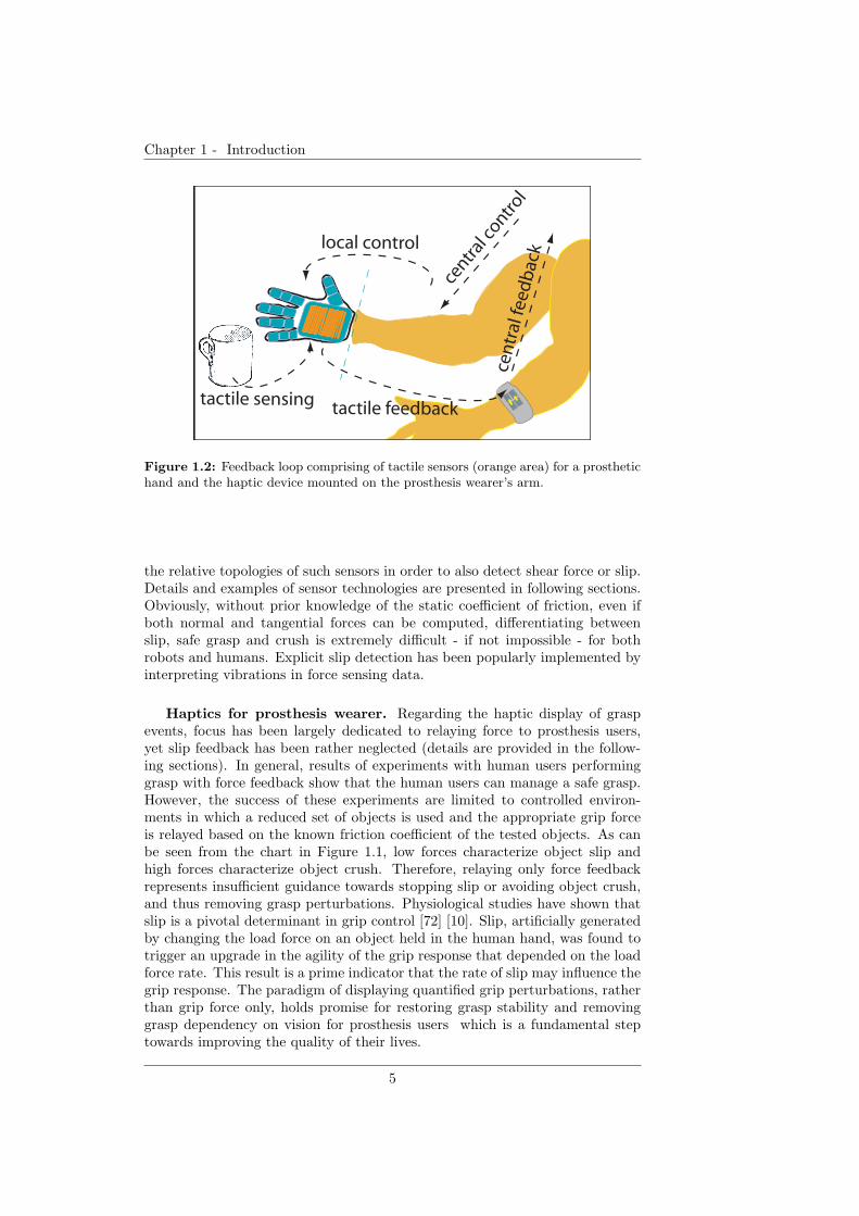
1.2 Feedback loop comprising of tactile sensors (orange area) for aprosthetic hand and the haptic device mounted on the prosthesiswearer’s arm. . . . . . . . . . . . . . . . . . . . . . . . . . . . . . 5
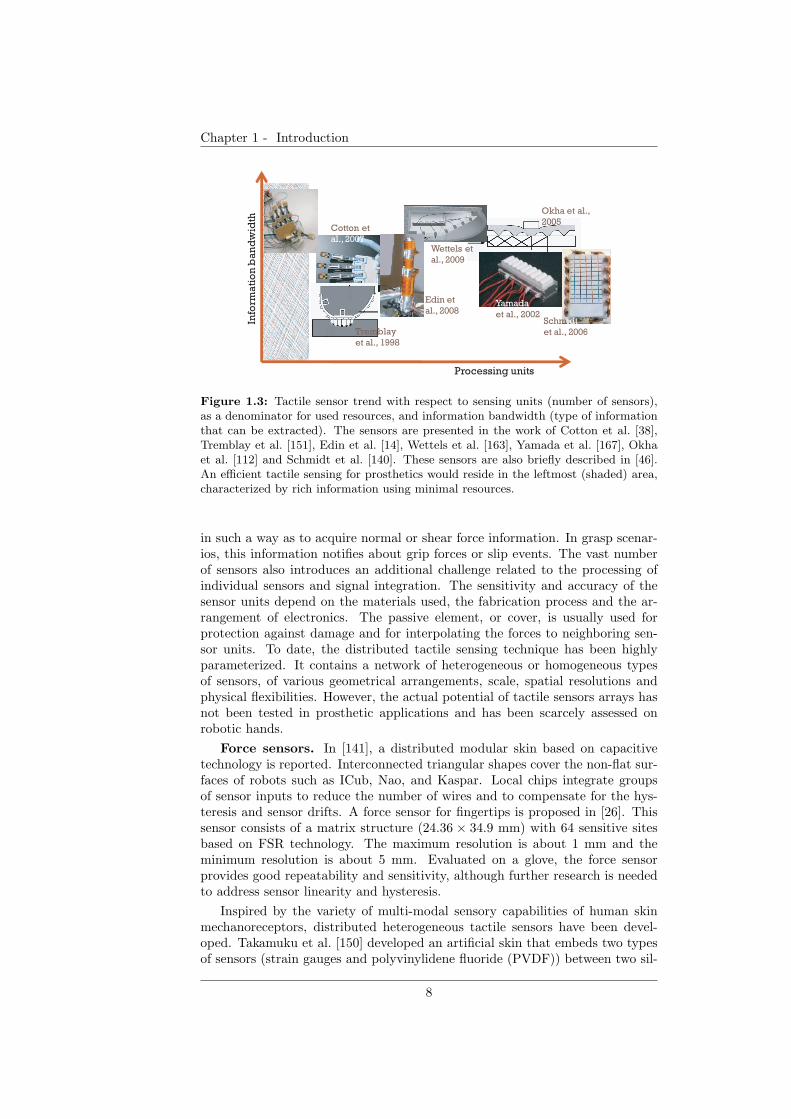
1.3 Tactile sensor trend with respect to sensing units (number ofsensors), as a denominator for used resources, and informationbandwidth (type of information that can be extracted). Thesensors are presented in the work of Cotton et al. [38], Tremblay etal. [151], Edin et al. [14], Wettels et al. [163], Yamada et al. [167],Okha et al. [112] and Schmidt et al. [140]. These sensors are alsobriefly described in [46]. An efficient tactile sensing for prostheticswould reside in the leftmost (shaded) area, characterized by richinformation using minimal resources. . . . . . . . . . . . . . . . . 8
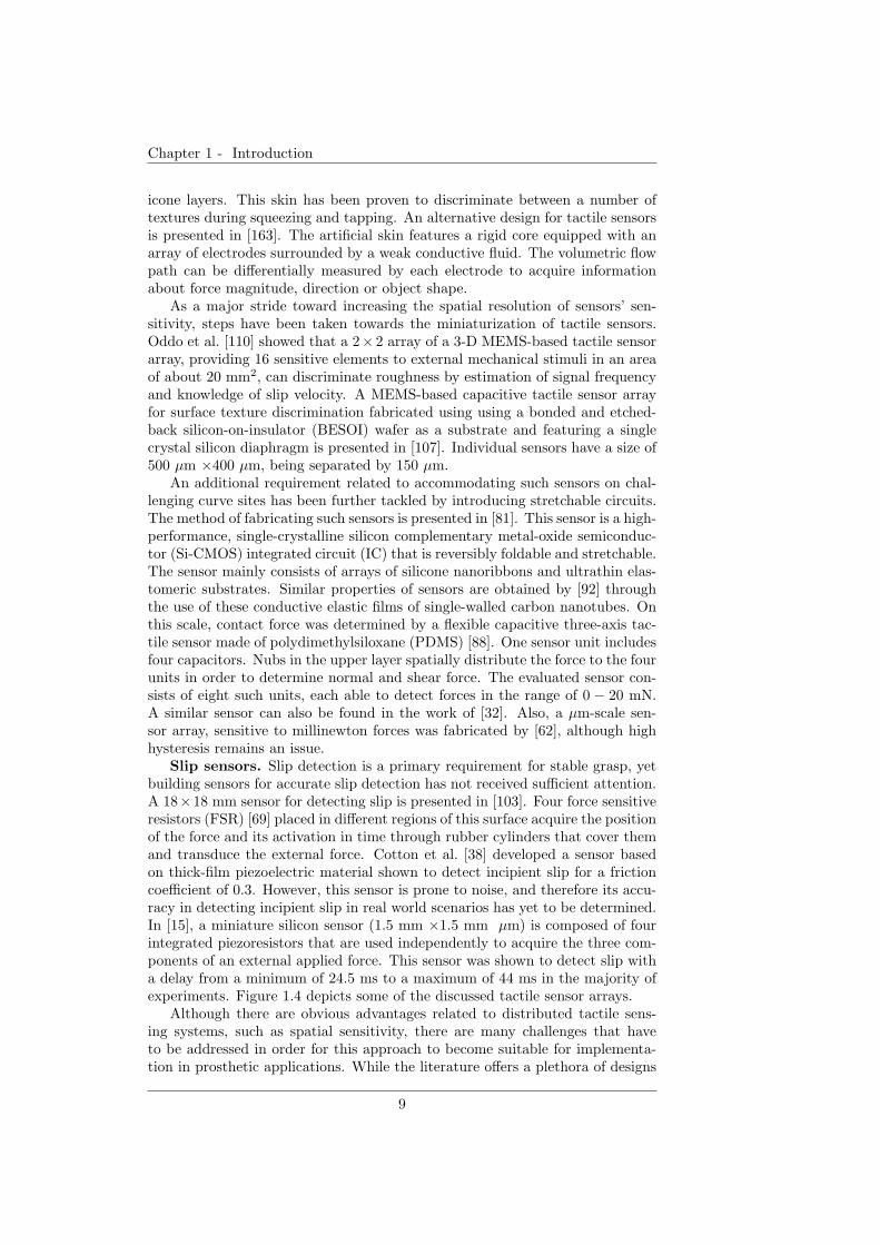
1.4 Tactile sensor arrays: Tactile sensing system based on capaci-tive technology for robotic grasp control [141](left), tactile sensorbased on 3D MEMS for texture discrimination [110] (middle),highly stretchable tactile sensor based on nanotechnology (right). 10
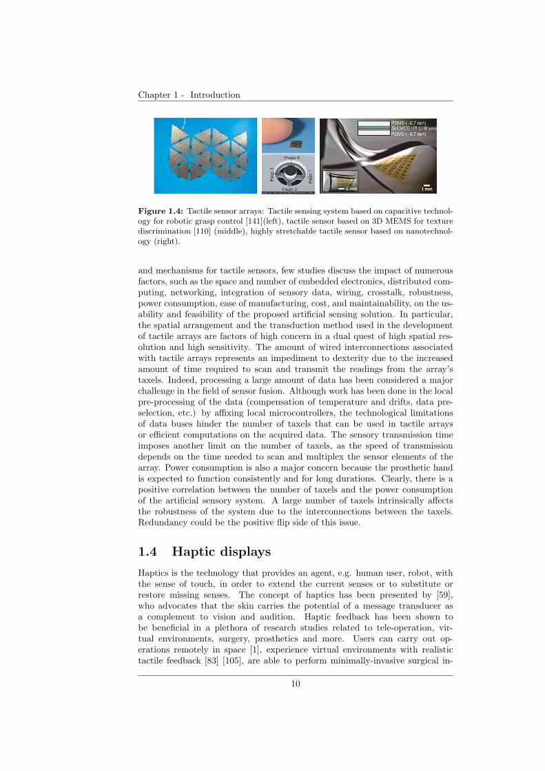
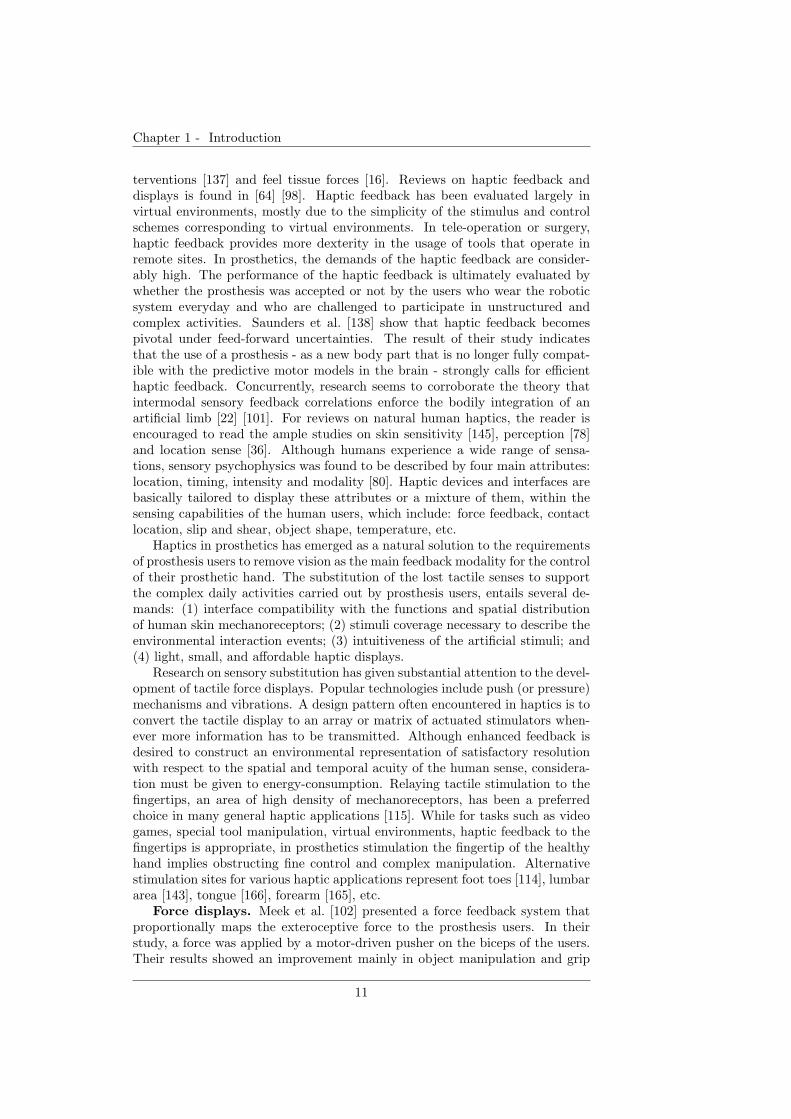
1.5 Tactile stimulation arrays. A. Multi-function haptic device fordisplaying touch, pressure, vibration, shear force and tempera-ture for patients that undergone reinnervation(TR) surgery [82].B. A 49 electrode array for tongue stimulation and pattern dis-play [166]. C. An array of motors to display forces for each handfinger by a push mechanism [4]. . . . . . . . . . . . . . . . . . . . 12
1.6 Difference between biology (left) and technology (right) with re-spect to scale and various resources used for solutions to prob-lems [157]. . . . . . . . . . . . . . . . . . . . . . . . . . . . . . . . 14
1.7 The structure of the core of the thesis. The first two chaptersinvestigate requirements for efficient grasp in upper-limb pros-theses. Chapters 4 and 5 focus on efficient tactile sensing. Thepotential of a ridged artificial skin is investigated for force, slipoccurrence, slip speed and location detection. Chapters 6, 7 and8 investigate an efficient tactile display to relay force and slip.Chapter 9 discusses the overall results of the thesis and futureresearch avenues. . . . . . . . . . . . . . . . . . . . . . . . . . . . 17
xi
LIST OF FIGURES
2.1 Experimental setup. A) The participant used electromyographic (EMG)signals to control the speed of a slipping object, while receivingvisual or electrotactile vibration feedback. Auditory feedbackremoved the noise and controlled the time progress of the ex-periment. B) Details of the platform on which the motor-drivenobject slipped. . . . . . . . . . . . . . . . . . . . . . . . . . . . . 22
2.2 Experimental procedure and control. A) Diagram of the experi-mental procedure within a session. One session consists of threephases in which the participant attempts to stop the slip. Speedvi is associated with and expects a contraction level ei, whereasej is the actual contraction level input by the user. Stopping anobject that slips at speed vi requires a muscle contraction levelof ej = ei (success). B) Schematics of the control flow for thetask of stopping the slipping object. I) Given that the objectslips at initial velocity vt, the participant receives notification byvision or slip occurrence feedback (bt) or by slip speed feedback(dt). II) The participant attempts to control slip by inputtinga muscle contraction. The acquired EMG signal, rt, is rectifiedand integrated into et. III) Function f maps a muscle contrac-tion level to the speed change that it can cause to the object.Depending on et and on velocity vt, the velocity of the objectchanges to vt+1. . . . . . . . . . . . . . . . . . . . . . . . . . . . 25
2.3 Promptness to stop slip relative to the slip speed and the feedbackmodality. The percentage of successes in the first phase (column1), second phase (column 2), and third phase (column 3). Thepercentage of failures to stop slip within the first three phases(column 4). The slip speeds are: 1.8 mm/s (A), 3.2 mm/s (B),4.6 mm/s (C), and 6.0 mm/s (D). Each column compares thethree types of feedback modalities: vision (brown), slip occur-rence stimulation, SOS (orange), and slip speed stimulation, SSS(green). The confidence interval of the results is 95%. The resultsshow that at high slip speeds the slip speed feedback and vision,in contrast to the slip occurrence feedback, manage to stop slip inthe early stages of its occurrence. Thick-border columns denotethe conditions in which significant difference was found. . . . . . 31
2.4 Success-to-EMG-intensity ratio relative to the slip speed and thefeedback modality. The four velocities are: 1.8 mm/s (column1), 3.2 mm/s (column 2), 4.6 mm/s (column 3), and 6.0 mm/s(column 4). Each column compares the three types of feedbackmodalities: vision (brown), slip occurrence stimulation, BF (or-ange), and slip speed stimulation, DF (green). The confidenceinterval of the results is 95%. The results indicate that the slipspeed stimulation maintains a relative increase of the success-to-EMG-intensity ratio as the slip speed becomes larger. . . . . . . 32
xii
LIST OF FIGURES
2.5 Level drifts of contraction intensity. A) Mask matrix for comput-ing level drifts of contraction intensity based on the presented slipspeed, v, and the actual contraction intensity level, e. Level L5indicates the equality between the expected and the actual levelof contraction intensity. The number of contractions (as a per-centage) corresponding to each level drift for visual feedback (B),slip occurrence feedback (C), and slip speed feedback (D). Theconfidence interval of the results is 95%. The plots show that theslip speed feedback and vision, compared to the slip occurrencefeedback, reduce the variation of muscle contraction input. . . . . 34
2.6 Reaction time to slip. A. Reaction time relative to the feedbackmodality (vision, slip occurrence feedback (BF) and slip speedfeedback (DF)). B. Reaction time relative to the slip speed. Onaverage, the reaction time to slip was in the range of 1.51 −1.75 s for all three feedback modalities and four slip speeds. Theconfidence interval of the results is 95%. . . . . . . . . . . . . . . 35
3.1 Schematics of the experimental setup. A. The artificial ridgedskin on which an object of weight W slips with speed v. B. Thescreen displaying to the participant graphical information aboutgrip force or slip speed feedback. C. Participant controls the slipvia a joystick. D. The robot hand controlled by the user. . . . . . 41
3.2 Elements of the experimental setup. A. Artificial ridged skin.B. Schematics of the artificial ridged skin illustrating the maincomponents. The triangular side L = 6 mm and the inter-ridgedistance D = 10 mm. C. Artificial ridged skin mounted on therobot hand and the slipping object. D. Screen showing feedbackguidance and performance feedback. . . . . . . . . . . . . . . . . 42
3.3 Grasp force with respect to object weight with force feedbackguidance alone (A), slip speed feedback guidance alone(B), forceand slip speed feedback guidance combined (C). Slip margin des-ignates the grip force level under which the object starts to slip.This level was determined empirically with the robot hand plat-form. . . . . . . . . . . . . . . . . . . . . . . . . . . . . . . . . . . 45
3.4 Reaction time with respect to computed slip speed with forcefeedback guidance alone. . . . . . . . . . . . . . . . . . . . . . . . 47
3.5 Reaction time with respect to actual slip speed with slip speedfeedback guidance alone (blue) and force and slip speed feedback(green). . . . . . . . . . . . . . . . . . . . . . . . . . . . . . . . . 47
3.6 Success to stop slip in time and reach an optimal grasp force, rel-ative to force feedback guidance (F), slip speed feedback guidance(SS) and the combined feedback guidance (F&SS). . . . . . . . . 49
4.1 Robotic hand equipped with artificial ridged skin. . . . . . . . . 52
4.2 The fabrication process of the ridged skin. a) Sample of ridgedskin. b) Force Sensing Resistor. c) Artificial skin layers. . . . . . 54
4.3 Force analysis at slippage. a) Object presses on the ridges. b)Object deforms laterally the first ridge encountered in the movingdirection. c) Detail on the forces in case b). . . . . . . . . . . . 55
xiii
LIST OF FIGURES
4.4 FSR model. a) Experimental setup for creating the model. b)Time series of raw FSR (red), pulling force (green) and resultingFSR model (magenta). c) Frequency spectrum of raw FSR andmodel FSR showing identical peak frequencies of 0.315Hz. . . . . 56
4.5 Distribution in voltage magnitude as a response to different ob-ject weights and inter-ridge distances Drr. . . . . . . . . . . . . 57
4.6 Time profiles for slippage signals generated by an object slidingat same speed over skins of different inter-ridge distances Drr. . . 58
4.7 Peak frequencies of slippage signal at three velocities as elicitedby skins with different inter-ridge distances Drr. . . . . . . . . . 59
4.8 Schematics of tactile sensing system. Artificial skin encodes slip-page whose speed is further encoded into vibration pulse fre-quency for stimulating user’s skin in prosthetic applications. . . . 60
4.9 Performance in robotic hand grip stabilization, as a response toobject slippage at six speeds. . . . . . . . . . . . . . . . . . . . . 61
4.10 Feedback stimulation patterns. a) Two slippage signals with fre-quencies of 2Hz (top) and 4Hz (bottom). b) Expected stimula-tion pulses corresponding to signals in a). . . . . . . . . . . . . . 62
5.1 Arrangement of ridges on the artificial skin equipped with a forcesensor. A. Uniform distribution of ridges. B. Non-uniform dis-tribution of ridges. Ds represent the inter-ridge spacing. For theskin in case A, the inter-ridge distances are identical (D). . . . . 68
5.2 Algorithm for testing the design parameters of the skin. Basedon a simulated force signal, s(t), the algorithm reconstructs theposition, X, and speed, V , of a slipping object. The distancebetween consecutive detected peaks, PK, are subjected to a ratiocomputation described in step 1, and compared to ratio of inter-ridge distances, D, which are known a priori. The performancein detecting the position and speed is used as a criterion for theridge distribution selection (step 2). . . . . . . . . . . . . . . . . 70
5.3 Search space of the evolutionary algorithm with respect to the twoobjective functions, accuracy in speed/position detection (Accu-racy, A) and ridge distribution (Resolution, R). The search spaceis shown for skins with α = 0.1 (A), α = 0.5 (B) and α = 0.9(C). The blue circles represent local minimums, while the red cir-cle represents the local minimum determined by the evolutionaryalgorithm. The lines represent the linear fitness function as afunction of α. . . . . . . . . . . . . . . . . . . . . . . . . . . . . . 73
5.4 Score of six skin spacings configurations. The two groups repre-sent the two criteria for the selection of the spacings: accuracyand resolution of detection of speed and position. . . . . . . . . . 74
5.5 Real ridged skins. A-C. Skin components and fabrication. A.Example of silicone molded with triangular ridges. B. Transverseview of the layers of the skin. L = 2.5 mm. D1 and D7 aregeneric spacing values. C. Long force sensitive resistor. D-G.Example of the arrangement of ridges on the artificial skin. D.Skin with α = 0.5. E. Skin with α = 0.3. F. Skin with α = 0.1.G. Fibonacci skin. . . . . . . . . . . . . . . . . . . . . . . . . . . 75
xiv
LIST OF FIGURES
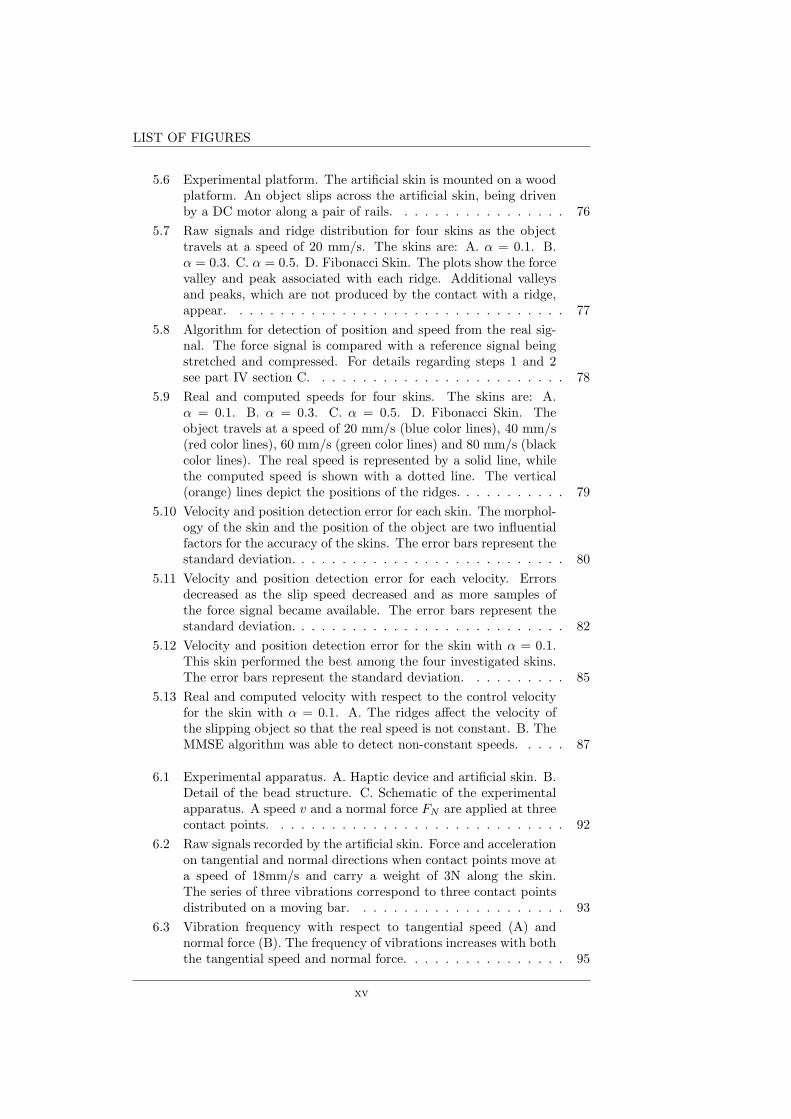
5.6 Experimental platform. The artificial skin is mounted on a woodplatform. An object slips across the artificial skin, being drivenby a DC motor along a pair of rails. . . . . . . . . . . . . . . . . 76
5.7 Raw signals and ridge distribution for four skins as the objecttravels at a speed of 20 mm/s. The skins are: A. α = 0.1. B.α = 0.3. C. α = 0.5. D. Fibonacci Skin. The plots show the forcevalley and peak associated with each ridge. Additional valleysand peaks, which are not produced by the contact with a ridge,appear. . . . . . . . . . . . . . . . . . . . . . . . . . . . . . . . . 77
5.8 Algorithm for detection of position and speed from the real sig-nal. The force signal is compared with a reference signal beingstretched and compressed. For details regarding steps 1 and 2see part IV section C. . . . . . . . . . . . . . . . . . . . . . . . . 78
5.9 Real and computed speeds for four skins. The skins are: A.α = 0.1. B. α = 0.3. C. α = 0.5. D. Fibonacci Skin. Theobject travels at a speed of 20 mm/s (blue color lines), 40 mm/s(red color lines), 60 mm/s (green color lines) and 80 mm/s (blackcolor lines). The real speed is represented by a solid line, whilethe computed speed is shown with a dotted line. The vertical(orange) lines depict the positions of the ridges. . . . . . . . . . . 79
5.10 Velocity and position detection error for each skin. The morphol-ogy of the skin and the position of the object are two influentialfactors for the accuracy of the skins. The error bars represent thestandard deviation. . . . . . . . . . . . . . . . . . . . . . . . . . . 80
5.11 Velocity and position detection error for each velocity. Errorsdecreased as the slip speed decreased and as more samples ofthe force signal became available. The error bars represent thestandard deviation. . . . . . . . . . . . . . . . . . . . . . . . . . . 82
5.12 Velocity and position detection error for the skin with α = 0.1.This skin performed the best among the four investigated skins.The error bars represent the standard deviation. . . . . . . . . . 85
5.13 Real and computed velocity with respect to the control velocityfor the skin with α = 0.1. A. The ridges affect the velocity ofthe slipping object so that the real speed is not constant. B. TheMMSE algorithm was able to detect non-constant speeds. . . . . 87
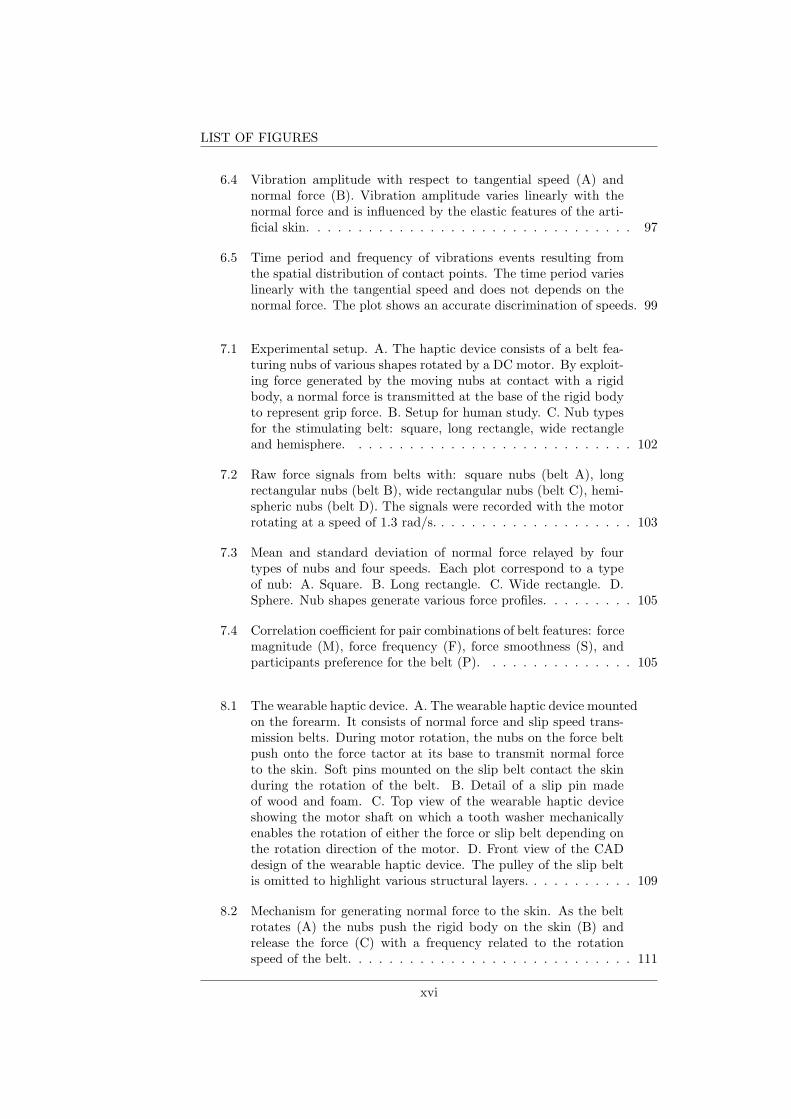
6.1 Experimental apparatus. A. Haptic device and artificial skin. B.Detail of the bead structure. C. Schematic of the experimentalapparatus. A speed v and a normal force FN are applied at threecontact points. . . . . . . . . . . . . . . . . . . . . . . . . . . . . 92
6.2 Raw signals recorded by the artificial skin. Force and accelerationon tangential and normal directions when contact points move ata speed of 18mm/s and carry a weight of 3N along the skin.The series of three vibrations correspond to three contact pointsdistributed on a moving bar. . . . . . . . . . . . . . . . . . . . . 93
6.3 Vibration frequency with respect to tangential speed (A) andnormal force (B). The frequency of vibrations increases with boththe tangential speed and normal force. . . . . . . . . . . . . . . . 95
xv
LIST OF FIGURES
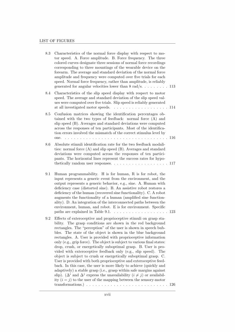
6.4 Vibration amplitude with respect to tangential speed (A) andnormal force (B). Vibration amplitude varies linearly with thenormal force and is influenced by the elastic features of the arti-ficial skin. . . . . . . . . . . . . . . . . . . . . . . . . . . . . . . . 97
6.5 Time period and frequency of vibrations events resulting fromthe spatial distribution of contact points. The time period varieslinearly with the tangential speed and does not depends on thenormal force. The plot shows an accurate discrimination of speeds. 99
7.1 Experimental setup. A. The haptic device consists of a belt fea-turing nubs of various shapes rotated by a DC motor. By exploit-ing force generated by the moving nubs at contact with a rigidbody, a normal force is transmitted at the base of the rigid bodyto represent grip force. B. Setup for human study. C. Nub typesfor the stimulating belt: square, long rectangle, wide rectangleand hemisphere. . . . . . . . . . . . . . . . . . . . . . . . . . . . 102
7.2 Raw force signals from belts with: square nubs (belt A), longrectangular nubs (belt B), wide rectangular nubs (belt C), hemi-spheric nubs (belt D). The signals were recorded with the motorrotating at a speed of 1.3 rad/s. . . . . . . . . . . . . . . . . . . . 103
7.3 Mean and standard deviation of normal force relayed by fourtypes of nubs and four speeds. Each plot correspond to a typeof nub: A. Square. B. Long rectangle. C. Wide rectangle. D.Sphere. Nub shapes generate various force profiles. . . . . . . . . 105
7.4 Correlation coefficient for pair combinations of belt features: forcemagnitude (M), force frequency (F), force smoothness (S), andparticipants preference for the belt (P). . . . . . . . . . . . . . . 105
8.1 The wearable haptic device. A. The wearable haptic device mountedon the forearm. It consists of normal force and slip speed trans-mission belts. During motor rotation, the nubs on the force beltpush onto the force tactor at its base to transmit normal forceto the skin. Soft pins mounted on the slip belt contact the skinduring the rotation of the belt. B. Detail of a slip pin madeof wood and foam. C. Top view of the wearable haptic deviceshowing the motor shaft on which a tooth washer mechanicallyenables the rotation of either the force or slip belt depending onthe rotation direction of the motor. D. Front view of the CADdesign of the wearable haptic device. The pulley of the slip beltis omitted to highlight various structural layers. . . . . . . . . . . 109
8.2 Mechanism for generating normal force to the skin. As the beltrotates (A) the nubs push the rigid body on the skin (B) andrelease the force (C) with a frequency related to the rotationspeed of the belt. . . . . . . . . . . . . . . . . . . . . . . . . . . . 111
xvi
LIST OF FIGURES
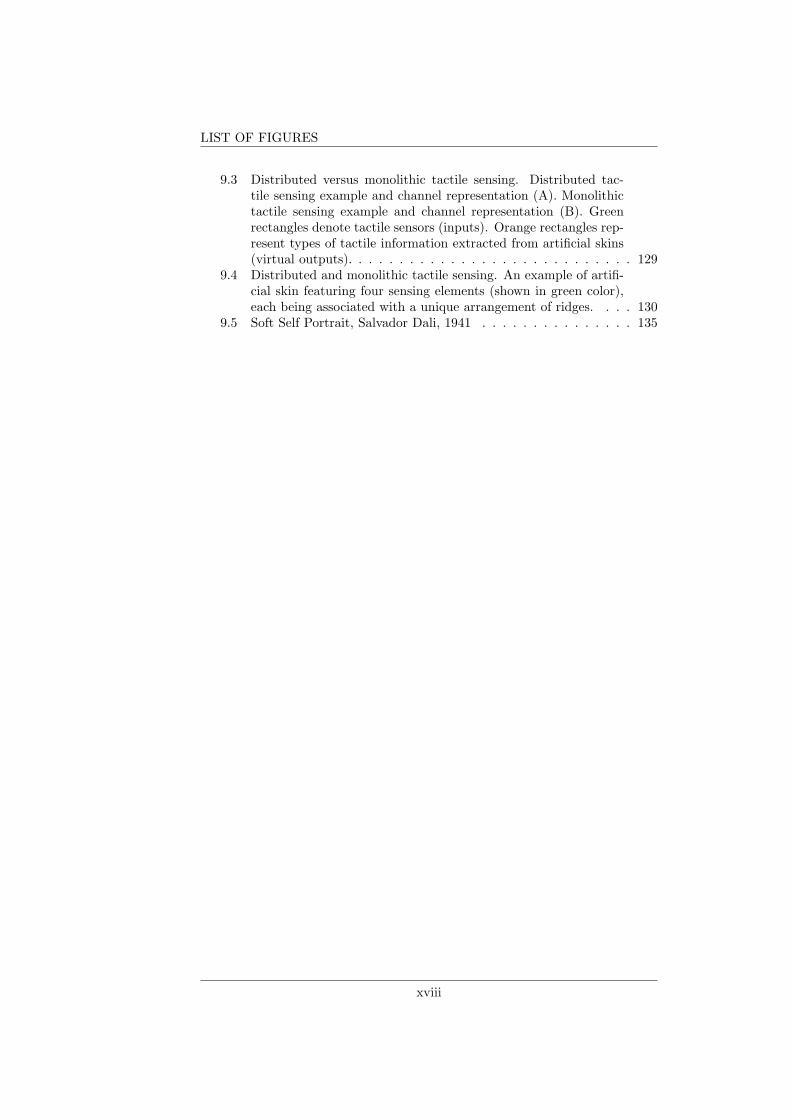
8.3 Characteristics of the normal force display with respect to mo-tor speed. A. Force amplitude. B. Force frequency. The threecolored curves designate three sessions of normal force recordingscorresponding to three mountings of the wearable device on theforearm. The average and standard deviation of the normal forceamplitude and frequency were computed over five trials for eachspeed. Normal force frequency, rather than amplitude, is reliablygenerated for angular velocities lower than 8 rad/s. . . . . . . . . 113
8.4 Characteristics of the slip speed display with respect to motorspeed. The average and standard deviation of the slip speed val-ues were computed over five trials. Slip speed is reliably generatedat all investigated motor speeds. . . . . . . . . . . . . . . . . . . 114
8.5 Confusion matrices showing the identification percentages ob-tained with the two types of feedback: normal force (A) andslip speed (B). Averages and standard deviations were computedacross the responses of ten participants. Most of the identifica-tion errors involved the mismatch of the correct stimulus level byone. . . . . . . . . . . . . . . . . . . . . . . . . . . . . . . . . . . 116
8.6 Absolute stimuli identification rate for the two feedback modali-ties: normal force (A) and slip speed (B). Averages and standarddeviations were computed across the responses of ten partici-pants. The horizontal lines represent the success rates for hypo-thetically random user responses. . . . . . . . . . . . . . . . . . . 117
9.1 Human programmability. H is for human, R is for robot, theinput represents a generic event from the environment, and theoutput represents a generic behavior, e.g., sine. A. Human withdeficiency case (distorted sine). B. An assistive robot restores adeficiency of the human (recovered sine functionality). C. A robotaugments the functionality of a human (amplified sine function-ality). D. An integration of the interconnected paths between theenvironment, human, and robot. E is for environment. Specificpaths are explained in Table 9.1. . . . . . . . . . . . . . . . . . . 123
9.2 Effects of exteroceptive and proprioceptive stimuli on grasp sta-bility. The grasp conditions are shown in the red backgroundrectangles. The “perception” of the user is shown in speech bub-bles. The state of the object is shown in the blue backgroundrectangles. A. User is provided with proprioceptive informationonly (e.g., grip force). The object is subject to various final states:drop, crush, or energetically suboptimal grasp. B. User is pro-vided with exteroceptive feedback only (e.g., slip speed). Theobject is subject to crush or energetically suboptimal grasp. C.User is provided with both proprioceptive and exteroceptive feed-back. In this case, the user is more likely to achieve (quickly andadaptively) a stable grasp (i.e., grasp within safe margins againstslip). (∆i and ∆j express the unavailability (i 6= j) or availabil-ity (i = j) to the user of the mapping between the sensory-motortransformations.) . . . . . . . . . . . . . . . . . . . . . . . . . . . 126
xvii
LIST OF FIGURES
9.3 Distributed versus monolithic tactile sensing. Distributed tac-tile sensing example and channel representation (A). Monolithictactile sensing example and channel representation (B). Greenrectangles denote tactile sensors (inputs). Orange rectangles rep-resent types of tactile information extracted from artificial skins(virtual outputs). . . . . . . . . . . . . . . . . . . . . . . . . . . . 129
9.4 Distributed and monolithic tactile sensing. An example of artifi-cial skin featuring four sensing elements (shown in green color),each being associated with a unique arrangement of ridges. . . . 130
9.5 Soft Self Portrait, Salvador Dali, 1941 . . . . . . . . . . . . . . . 135
xviii
List of Tables
1.1 Economical tactile sensing and distributed tactile sensing. . . . . 151.2 Economical haptic display and distributed haptic display. . . . . 15
5.1 Results of GA. . . . . . . . . . . . . . . . . . . . . . . . . . . . . 895.2 Normalized root-mean-square deviation (NRMSD) of speed (V)
and position(P). . . . . . . . . . . . . . . . . . . . . . . . . . . . 90
6.1 P-values from ANOVA for the vibration frequency as a functionof tangential speed (A) and normal force (B). . . . . . . . . . . . 96
6.2 P-values from ANOVA for the vibration amplitude as a functionof tangential speed (A) and normal force (B). . . . . . . . . . . . 98
9.1 Human-robot-environment (HRE). The numbers represent a se-quence of connections defined in Fig. 9.1D. . . . . . . . . . . . . 123
9.2 Distributed (DTS) versus monolithic (MTS) tactile sensing metrics129
xix

LIST OF TABLES
xx

xxi
Chapter 1
Introduction
Who am I? - This is an eternal question that has fascinated many philosophers,from Aristotle to Descartes and to minds of the present. It has taken on variousanswers under the concepts of “substance”, “soul”, “thoughts”, etc. Science, ingeneral, and robotics, in particular, have been an outstanding source of enlight-enment for many questions of humanity, grounding our existence in sensible andconcise theories. A bottom-up approach to living systems by means of roboticshas been proving its potential in explaining and synthesizing complex notionsand behaviors that emerge as a consequence of an embodied interaction amongbodies and environments through various scales [122]. Robotic self-assembly hasrevealed interesting properties through the embodied dynamical interactions ofsmall-scale robots, possibly related to the emergence of life [104]. Sophisticatedlocomotion has been shown to rely on passive mechanisms [37] or soft mate-rial designs [144] in interaction with the environment. Soft manipulators [24] [8]have demystified the intriguing phenomenon of grasping, once viewed as a highlydemanding computational process and now seen as a compliant physical inter-action between the hand’s micro- and macro-structures and the manipulatedobjects. Prosthetics, as a robotic field within the human-robot-environmentinteraction discipline, has brought significant contributions to restoring the in-tegrity of physically challenged people. At the same time, it sheds more lighton the meaning of the Self by using robotic devices as parts of humans.
This thesis explores the requirements and design principles that may con-tribute to the incorporation of robotic devices into the human body, with re-spect to haptic interfaces (haptic sensors and displays). The context in whichthis thesis is situated is upper-limb prosthetics. By building robotic devices andsynthesizing artificial interfaces between the human and the prosthetic hand,we introduce a means to restore complete embodied interactions between theprosthesis wearer and the environment, and shed light on principles that maycontribute to the bodily incorporation of robotic devices.
1.1 Subject-object division for prosthetics
Prosthetics is an instance of the expression of the subject-object division, inwhich the subject is the amputee and the object is his prosthesis. The grandchallenge in prosthetics has been the realization of a transparent amputee-
1
Chapter 1 - Introduction
prosthesis interface insofar as the prosthesis is no longer an object or tool, buta part of the subject. Although the notion of Self has remained abstract [48],it is a useful reference concept in characterizing prosthetics or rehabilitationprocesses that have arisen the field of robotics and neuroscience.
Philipona et al. [124] define the self of a linked body, in opposition to theenvironment, as a correlated flow of sensory stimulation, under displacement (ormovement) conditions performed by the linked body. This congruency betweenthe sensory and motor flow is a powerful theoretical indicator that sensoryfeedback is critical for resolving the subject-object division present in pros-thetic applications. Partly, this hypothesis has been supported by experimentalwork [25] [111] [155].
1.1.1 Grasp stability
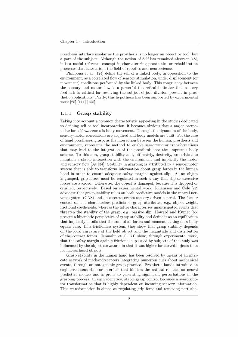
Taking into account a common characteristic appearing in the studies dedicatedto defining self or tool incorporation, it becomes obvious that a major prereq-uisite for self awareness is body movement. Through the dynamics of the body,sensory-motor correlations are acquired and body models are built. For the caseof hand prostheses, grasp, as the interaction between the human, prosthesis andenvironment, represents the method to enable sensorymotor transformationsthat may lead to the integration of the prosthesis into the amputee’s bodyscheme. To this aim, grasp stability and, ultimately, dexterity, are critical tomaintain a stable interaction with the environment and implicitly the motorand sensory flow [39] [34]. Stability in grasping is attributed to a sensorimotorsystem that is able to transform information about grasp forces in the humanhand in order to ensure adequate safety margins against slip. As an objectis grasped, grip forces must be regulated in such a way that slip or excessiveforces are avoided. Otherwise, the object is damaged, because it is dropped orcrushed, respectively. Based on experimental work, Johansson and Cole [72]advocate that grasp stability relies on both predictive models in the central ner-vous system (CNS) and on discrete events sensory-driven control. The formercontrol scheme characterizes predictable grasp attributes, e.g., object weight,frictional coefficients, whereas the latter characterizes unanticipated events thatthreaten the stability of the grasp, e.g. passive slip. Howard and Kumar [66]present a kinematic perspective of grasp stability and define it as an equilibriumthat implicitly entails that the sum of all forces and moments acting on a bodyequals zero. In a frictionless system, they show that grasp stability dependson the local curvature of the held object and the magnitude and distributionof the contact forces. Jenmalm et al. [71] show, through experimental work,that the safety margin against frictional slips used by subjects of the study wasinfluenced by the object curvature, in that it was higher for curved objects thanfor flat-surfaced objects.
Grasp stability in the human hand has been resolved by means of an intri-cate network of mechanoreceptors integrating numerous cues about mechanicalevents, through an ontogenetic grasp practice. Prosthetic hands introduce anengineered sensorimotor interface that hinders the natural reliance on neuralpredictive models and is prone to generating significant perturbations in thegrasping process. In such scenarios, stable grasp control becomes a sensorimo-tor transformation that is highly dependent on incoming sensory information.This transformation is aimed at regulating grip force and removing perturba-
2

Chapter 1 - Introduction
Excessive grip forceInsufficient grip force
Object
drop
Object
slip
Optimally
gripped
object
Object
overpress
Object
crush
Slip region Force regionGrip stability
Grip force
Grip force
Load force
No grip force
Slip magnitudeForce magnitude
Efficient grip force
Figure 1.1: Grasp stability chart. A. Load and grip forces in grasping. B. Regionsof stability and instability.
tions such as slip and excessive force, which can damage the held object or causeunnecessary energy use. This thesis strongly relies on this hypothesis. Based onthis kind of characterization of the grasp using prostheses, this thesis providesa novel approach to grasp, by largely taking into account perturbations andexploiting them in order to achieve a stable and sustainable grasp.
1.1.2 “Human-in-the-loop” grasp
There exist two main approaches to grasp stability in upper-limb prosthesesthat differ in the type of grasp control. Automatic grasp control is an approachin which the grip is performed by internal mechanism of the robotic hand trig-gered by grasp events detected by tactile sensors, with no human intervention.It relies on various transduction methods for slip and force detection to au-tomatically adjust the grip force of a robot hand, e.g., [135] [85] [162]. Thistype of technology has also been implemented into commercially available pros-thetic hands, e.g., those manufactured by Otto Bock [65] and RSL Steeper [149].Automatic grasping relies heavily on elaborating the complex deterministic al-gorithms necessary for grasp planning with robot hands, based on actuator’sencoders or touch/tactile sensors. In many cases, such algorithms assume thata number of geometric and material properties related to the held object or handare a priori available. While this analytic approach provides a fundamental un-derstanding of grasp, it also requires prior knowledge that is generally lackingin unstructured environments. The analytical formulation considers grasp asa set of contacts between the object and the robot hand, and further takesinto account the normal force, the tangential force, and the torsional momentaround the normal at each point of contact. Using this terminology, the staticequilibrium of the object can be defined, and the interaction forces of the graspcan be determined through various optimization methods. Nonetheless, thissolution does not guarantee stability unless grasp is considered as a dynamicalsystem. The complexity of the algorithms increases with the complexity of theobject model and the kinematics of the fingers. A detailed review on this topiccan be found in [17]. Recent work in hand neurophysiology [136] suggests thatpostural hand synergies are involved in tool grasping, of which two accountfor more than 80% of grasp variance. These findings have inspired automaticgrasp strategies that reduce the dimensionality of the parameters, e.g., degreesof freedom (DOFs), used for planning robotic grasps [34]. Gabiccini et al. [58]show through theoretical work that optimal contact forces strongly depend onthe selection of postural synergies and that the first two synergies, generated by
3
Chapter 1 - Introduction
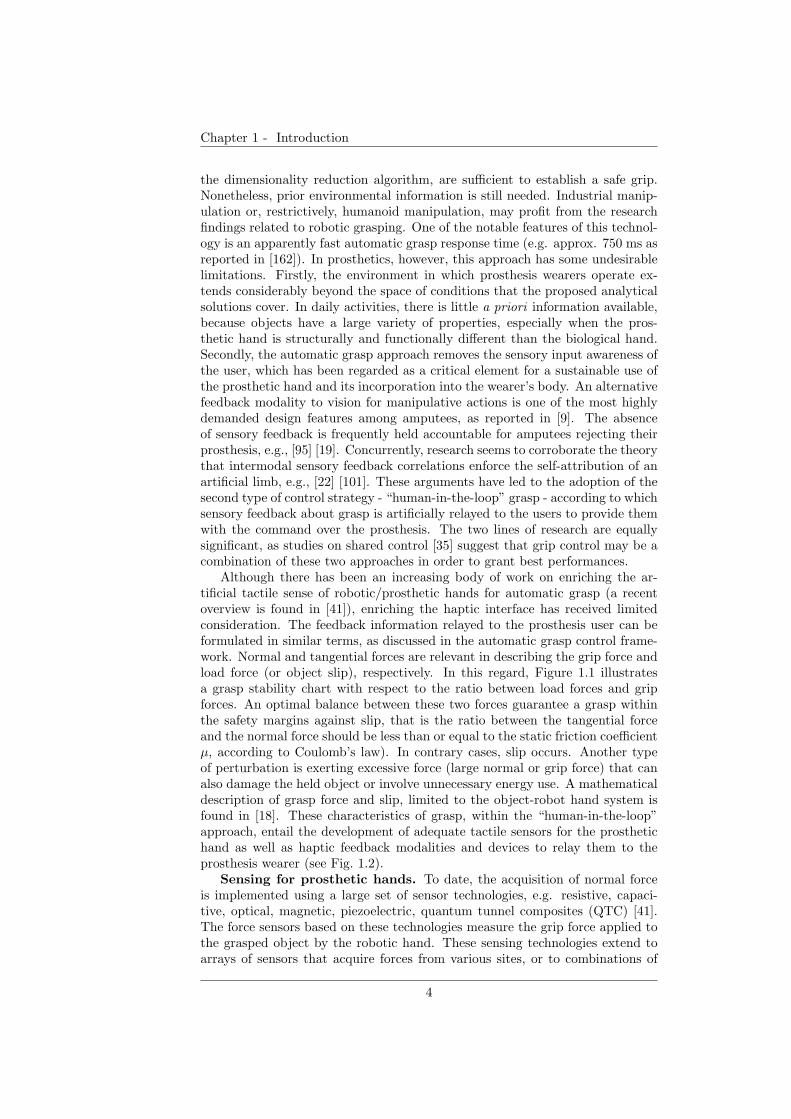
the dimensionality reduction algorithm, are sufficient to establish a safe grip.Nonetheless, prior environmental information is still needed. Industrial manip-ulation or, restrictively, humanoid manipulation, may profit from the researchfindings related to robotic grasping. One of the notable features of this technol-ogy is an apparently fast automatic grasp response time (e.g. approx. 750 ms asreported in [162]). In prosthetics, however, this approach has some undesirablelimitations. Firstly, the environment in which prosthesis wearers operate ex-tends considerably beyond the space of conditions that the proposed analyticalsolutions cover. In daily activities, there is little a priori information available,because objects have a large variety of properties, especially when the pros-thetic hand is structurally and functionally different than the biological hand.Secondly, the automatic grasp approach removes the sensory input awareness ofthe user, which has been regarded as a critical element for a sustainable use ofthe prosthetic hand and its incorporation into the wearer’s body. An alternativefeedback modality to vision for manipulative actions is one of the most highlydemanded design features among amputees, as reported in [9]. The absenceof sensory feedback is frequently held accountable for amputees rejecting theirprosthesis, e.g., [95] [19]. Concurrently, research seems to corroborate the theorythat intermodal sensory feedback correlations enforce the self-attribution of anartificial limb, e.g., [22] [101]. These arguments have led to the adoption of thesecond type of control strategy - “human-in-the-loop” grasp - according to whichsensory feedback about grasp is artificially relayed to the users to provide themwith the command over the prosthesis. The two lines of research are equallysignificant, as studies on shared control [35] suggest that grip control may be acombination of these two approaches in order to grant best performances.
Although there has been an increasing body of work on enriching the ar-tificial tactile sense of robotic/prosthetic hands for automatic grasp (a recentoverview is found in [41]), enriching the haptic interface has received limitedconsideration. The feedback information relayed to the prosthesis user can beformulated in similar terms, as discussed in the automatic grasp control frame-work. Normal and tangential forces are relevant in describing the grip force andload force (or object slip), respectively. In this regard, Figure 1.1 illustratesa grasp stability chart with respect to the ratio between load forces and gripforces. An optimal balance between these two forces guarantee a grasp withinthe safety margins against slip, that is the ratio between the tangential forceand the normal force should be less than or equal to the static friction coefficientµ, according to Coulomb’s law). In contrary cases, slip occurs. Another typeof perturbation is exerting excessive force (large normal or grip force) that canalso damage the held object or involve unnecessary energy use. A mathematicaldescription of grasp force and slip, limited to the object-robot hand system isfound in [18]. These characteristics of grasp, within the “human-in-the-loop”approach, entail the development of adequate tactile sensors for the prosthetichand as well as haptic feedback modalities and devices to relay them to theprosthesis wearer (see Fig. 1.2).
Sensing for prosthetic hands. To date, the acquisition of normal forceis implemented using a large set of sensor technologies, e.g. resistive, capaci-tive, optical, magnetic, piezoelectric, quantum tunnel composites (QTC) [41].The force sensors based on these technologies measure the grip force applied tothe grasped object by the robotic hand. These sensing technologies extend toarrays of sensors that acquire forces from various sites, or to combinations of
4
Chapter 1 - Introduction
centr
al c
ontrol
cen
tral
fe
ed
bac
klocal control
tactile feedbacktactile sensing
Figure 1.2: Feedback loop comprising of tactile sensors (orange area) for a prosthetichand and the haptic device mounted on the prosthesis wearer’s arm.
the relative topologies of such sensors in order to also detect shear force or slip.Details and examples of sensor technologies are presented in following sections.Obviously, without prior knowledge of the static coefficient of friction, even ifboth normal and tangential forces can be computed, differentiating betweenslip, safe grasp and crush is extremely difficult - if not impossible - for bothrobots and humans. Explicit slip detection has been popularly implemented byinterpreting vibrations in force sensing data.
Haptics for prosthesis wearer. Regarding the haptic display of graspevents, focus has been largely dedicated to relaying force to prosthesis users,yet slip feedback has been rather neglected (details are provided in the follow-ing sections). In general, results of experiments with human users performinggrasp with force feedback show that the human users can manage a safe grasp.However, the success of these experiments are limited to controlled environ-ments in which a reduced set of objects is used and the appropriate grip forceis relayed based on the known friction coefficient of the tested objects. As canbe seen from the chart in Figure 1.1, low forces characterize object slip andhigh forces characterize object crush. Therefore, relaying only force feedbackrepresents insufficient guidance towards stopping slip or avoiding object crush,and thus removing grasp perturbations. Physiological studies have shown thatslip is a pivotal determinant in grip control [72] [10]. Slip, artificially generatedby changing the load force on an object held in the human hand, was found totrigger an upgrade in the agility of the grip response that depended on the loadforce rate. This result is a prime indicator that the rate of slip may influence thegrip response. The paradigm of displaying quantified grip perturbations, ratherthan grip force only, holds promise for restoring grasp stability and removinggrasp dependency on vision for prosthesis users which is a fundamental steptowards improving the quality of their lives.
5
Chapter 1 - Introduction
1.2 Requirements in prosthetics
Engineering the tactile sensing in prostheses as well as the fusion between theprosthetic hand and its user imposes high demands on the design of the sensoryinterface. The challenge can be categorized from two perspectives. Scientifi-cally, making the boundary between the subject (the amputee) and the object(the robot hand) less perceivable carries deep questions about the type andamount of sensory information necessary to incorporate the object in the sub-ject. Technologically, it is highly non-trivial to find an engineering solution thatis competitive in richness and sensitivity to the lost sensory interface. The roadto tapping into the Self, and in particular, to achieving the incorporation of therobot hand into the wearer’s body, require high demands in order for the pros-thetic hand to be more than a mere robotic tool. On the other hand, scientificlimitations and technological constraints are erecting barriers to reaching theserequirements. We will discuss both the demands and limitations in prostheticsin the following sections. The glabrous skin of the human hand is endowed withabout 17000 mechanoreceptors [74] and an immense computational capabilityto acquire and process them. It is, thus, a truly ambitious engineering task toreplicate a model of the human hand with prosthetics. Endeavors in developingprosthetic hands still face considerable difficulties in being accepted by the endusers.
As a result of various surveys, a list of requirements for the design of pros-thetic hands is compiled in what follows.
Sensory feedback. A priority demand among prosthesis wearers is the sen-sory feedback in manipulative tasks [9] [27] [118]. The survey findings has beenalso confirmed by neuroscience studies with amputees according to which visual,tactile and sensorimotor systems all contribute to phantom limb awareness [67].The absence of sensory feedback hinders the natural response of the prosthesisin accordance with the environmental stimuli [70]. Experiments conducted inthe study of [109] suggest that grip force control requires at least intermittentsensory feedback in order to update internal models of grasping. Previous stud-ies have shown that haptic displays enhanced manipulative task performancein terms of the interaction with virtual objects by about 50% and reduced thelearning time by 50% [127]. A comparison of grip force regulation using tactiledisplay and sensory substitution (both auditory and visual) indicates that tactiledisplay is more successful than sensory substitution. This is most likely becausethe tactile display mimicks the natural tactile sensation and is thus more intu-itive. Additionally, the redundancy offered by combining feedback modalitiesincreases performance in grip force regulation and dexterous manipulation [128].Although vision alone is able to provide sufficient information for maintainingobjects in the grip, evidence indicates that it entails higher grip forces than nec-essary [70]. Additionally, monitoring the prosthesis using vision alone limits thetasks that can be performed simultaneously and increases the cognitive effortrequired of prosthesis wearers [9] [128]. Restoring able-bodied quality proprio-ception and somatosensation is one of the pivotal factors in the sustainable useof prosthetic devices and their seamless integration into the body [60].
Energy-efficiency. Unsatisfactory power schemes for prostheses have beencited as a perennial issue [9]. One of the most frequent repairs or maintenanceprocedures that prosthesis wearers undergo is the replacement of the prostheticbattery [86]. A more efficient power/energy scheme would provide a longer life
6
Chapter 1 - Introduction
for the prosthesis and would endow amputees with the ability to increase theusage of their prosthesis. One argument is that the high-energy batteries avail-able for portable computers are not sufficient for prosthetic devices [33]. Whilethis argument remains sensible, the issue of energy consumption by prostheticdevices may find a solution through a change in the approach to prosthesis de-sign. Rather than building prosthetic devices by combining energy-consumingcomponents and increasing computational load, a careful consideration of themechanical design that outsources the functional and computational load to themorphology of the prosthesis may be the key to overcoming the energy issue.
Control abilities. As a result of surveys among prosthesis wearers, achiev-ing able-bodied levels of performance across tasks and across environments hasbeen classified as a priority [9] [27] [60] [118]. One statistical study suggeststhat about 30 − 50% of amputees wearing myoelectrically-controlled prosthe-ses do not use them regularly or do not use them at all due to low functionalcapabilities [146]. Prosthetic systems that enable stable and dexterous grasphave been a major research focus, yet this issue was mainly tackled from a purerobot control approach. Many prosthetic hands feature a high-number of ac-tuated joints, yet for amputees it is extremely difficult and counterintuitive tocontrol the many degrees of freedom of these dexterous prosthetic hands. Asa consequence, Otto Bock prosthetic hands provide one or two degrees of free-dom. This issue can be approached by outsourcing the computation pertainingto robotic control to the morphology of the hand. Evidence for the potential ofthis approach exists in the work of Dollar et al. [50] and Dermitzakis et al. [49].Gilja et al. [60] emphasize that an additional focus for future advancements mustbe robustness, implying that the prosthetic devices of the future should oper-ate over long periods of time and maintain their functionality across multipledecades.
Appearance. The appearance of the prosthetic hand seems to be among thehighest-ranked concerns of amputees [153] [86]. The prosthesis must preserve,at least to some extent, the mechanical properties of the biologic hand, suchas mass, center of mass, such that it does not generate unbalance or excessiveenergy in its use.
1.3 Tactile sensors
Technological advancements in multi-DOF robotic hands must be complementedby sensory capabilities in order to attain dexterous control. Providing that thehuman hand is one of the most sensitive areas of the body, the ability to senseforce, slip, vibration, contact, temperature, etc., represents a considerable chal-lenge for the engineering of tactile sensors for robotics or prosthetics. Figure 1.3provides a selection of the tactile sensors developed to date with respect to twodimensions: (1) the number of sensing elements and (2) the type of informationextracted from the tactile sensor, e.g., force, slip, temperature, etc. From thepoint of view of composition, tactile sensors usually contain an active element,i.e., energy consuming element, e.g., force sensor, slip sensor, etc., and a passiveelement, e.g., a polymer to cover the active elements.
Presently, there is an apparent tendency towards developing distributed tac-tile sensor arrays, which are matrices of active elements that acquire local in-formation from a large number of channels. Typically, these sensors are built
7
Chapter 1 - Introduction
Cotton et
al., 2007
Info
rma
tio
n b
an
dw
idth
Processing units
Edin et
al., 2008
Okha et al.,
2005
Wettels et
al., 2009
Tremblay
et al., 1998
Yamada
et al., 2002 Schmidt
et al., 2006
Figure 1.3: Tactile sensor trend with respect to sensing units (number of sensors),as a denominator for used resources, and information bandwidth (type of informationthat can be extracted). The sensors are presented in the work of Cotton et al. [38],Tremblay et al. [151], Edin et al. [14], Wettels et al. [163], Yamada et al. [167], Okhaet al. [112] and Schmidt et al. [140]. These sensors are also briefly described in [46].An efficient tactile sensing for prosthetics would reside in the leftmost (shaded) area,characterized by rich information using minimal resources.
in such a way as to acquire normal or shear force information. In grasp scenar-ios, this information notifies about grip forces or slip events. The vast numberof sensors also introduces an additional challenge related to the processing ofindividual sensors and signal integration. The sensitivity and accuracy of thesensor units depend on the materials used, the fabrication process and the ar-rangement of electronics. The passive element, or cover, is usually used forprotection against damage and for interpolating the forces to neighboring sen-sor units. To date, the distributed tactile sensing technique has been highlyparameterized. It contains a network of heterogeneous or homogeneous typesof sensors, of various geometrical arrangements, scale, spatial resolutions andphysical flexibilities. However, the actual potential of tactile sensors arrays hasnot been tested in prosthetic applications and has been scarcely assessed onrobotic hands.
Force sensors. In [141], a distributed modular skin based on capacitivetechnology is reported. Interconnected triangular shapes cover the non-flat sur-faces of robots such as ICub, Nao, and Kaspar. Local chips integrate groupsof sensor inputs to reduce the number of wires and to compensate for the hys-teresis and sensor drifts. A force sensor for fingertips is proposed in [26]. Thissensor consists of a matrix structure (24.36 × 34.9 mm) with 64 sensitive sitesbased on FSR technology. The maximum resolution is about 1 mm and theminimum resolution is about 5 mm. Evaluated on a glove, the force sensorprovides good repeatability and sensitivity, although further research is neededto address sensor linearity and hysteresis.
Inspired by the variety of multi-modal sensory capabilities of human skinmechanoreceptors, distributed heterogeneous tactile sensors have been devel-oped. Takamuku et al. [150] developed an artificial skin that embeds two typesof sensors (strain gauges and polyvinylidene fluoride (PVDF)) between two sil-
8
Chapter 1 - Introduction
icone layers. This skin has been proven to discriminate between a number oftextures during squeezing and tapping. An alternative design for tactile sensorsis presented in [163]. The artificial skin features a rigid core equipped with anarray of electrodes surrounded by a weak conductive fluid. The volumetric flowpath can be differentially measured by each electrode to acquire informationabout force magnitude, direction or object shape.
As a major stride toward increasing the spatial resolution of sensors’ sen-sitivity, steps have been taken towards the miniaturization of tactile sensors.Oddo et al. [110] showed that a 2× 2 array of a 3-D MEMS-based tactile sensorarray, providing 16 sensitive elements to external mechanical stimuli in an areaof about 20 mm2, can discriminate roughness by estimation of signal frequencyand knowledge of slip velocity. A MEMS-based capacitive tactile sensor arrayfor surface texture discrimination fabricated using using a bonded and etched-back silicon-on-insulator (BESOI) wafer as a substrate and featuring a singlecrystal silicon diaphragm is presented in [107]. Individual sensors have a size of500 µm ×400 µm, being separated by 150 µm.
An additional requirement related to accommodating such sensors on chal-lenging curve sites has been further tackled by introducing stretchable circuits.The method of fabricating such sensors is presented in [81]. This sensor is a high-performance, single-crystalline silicon complementary metal-oxide semiconduc-tor (Si-CMOS) integrated circuit (IC) that is reversibly foldable and stretchable.The sensor mainly consists of arrays of silicone nanoribbons and ultrathin elas-tomeric substrates. Similar properties of sensors are obtained by [92] throughthe use of these conductive elastic films of single-walled carbon nanotubes. Onthis scale, contact force was determined by a flexible capacitive three-axis tac-tile sensor made of polydimethylsiloxane (PDMS) [88]. One sensor unit includesfour capacitors. Nubs in the upper layer spatially distribute the force to the fourunits in order to determine normal and shear force. The evaluated sensor con-sists of eight such units, each able to detect forces in the range of 0 − 20 mN.A similar sensor can also be found in the work of [32]. Also, a µm-scale sen-sor array, sensitive to millinewton forces was fabricated by [62], although highhysteresis remains an issue.
Slip sensors. Slip detection is a primary requirement for stable grasp, yetbuilding sensors for accurate slip detection has not received sufficient attention.A 18×18 mm sensor for detecting slip is presented in [103]. Four force sensitiveresistors (FSR) [69] placed in different regions of this surface acquire the positionof the force and its activation in time through rubber cylinders that cover themand transduce the external force. Cotton et al. [38] developed a sensor basedon thick-film piezoelectric material shown to detect incipient slip for a frictioncoefficient of 0.3. However, this sensor is prone to noise, and therefore its accu-racy in detecting incipient slip in real world scenarios has yet to be determined.In [15], a miniature silicon sensor (1.5 mm ×1.5 mm µm) is composed of fourintegrated piezoresistors that are used independently to acquire the three com-ponents of an external applied force. This sensor was shown to detect slip witha delay from a minimum of 24.5 ms to a maximum of 44 ms in the majority ofexperiments. Figure 1.4 depicts some of the discussed tactile sensor arrays.
Although there are obvious advantages related to distributed tactile sens-ing systems, such as spatial sensitivity, there are many challenges that haveto be addressed in order for this approach to become suitable for implementa-tion in prosthetic applications. While the literature offers a plethora of designs
9
Chapter 1 - Introduction
Figure 1.4: Tactile sensor arrays: Tactile sensing system based on capacitive technol-ogy for robotic grasp control [141](left), tactile sensor based on 3D MEMS for texturediscrimination [110] (middle), highly stretchable tactile sensor based on nanotechnol-ogy (right).
and mechanisms for tactile sensors, few studies discuss the impact of numerousfactors, such as the space and number of embedded electronics, distributed com-puting, networking, integration of sensory data, wiring, crosstalk, robustness,power consumption, ease of manufacturing, cost, and maintainability, on the us-ability and feasibility of the proposed artificial sensing solution. In particular,the spatial arrangement and the transduction method used in the developmentof tactile arrays are factors of high concern in a dual quest of high spatial res-olution and high sensitivity. The amount of wired interconnections associatedwith tactile arrays represents an impediment to dexterity due to the increasedamount of time required to scan and transmit the readings from the array’staxels. Indeed, processing a large amount of data has been considered a majorchallenge in the field of sensor fusion. Although work has been done in the localpre-processing of the data (compensation of temperature and drifts, data pre-selection, etc.) by affixing local microcontrollers, the technological limitationsof data buses hinder the number of taxels that can be used in tactile arraysor efficient computations on the acquired data. The sensory transmission timeimposes another limit on the number of taxels, as the speed of transmissiondepends on the time needed to scan and multiplex the sensor elements of thearray. Power consumption is also a major concern because the prosthetic handis expected to function consistently and for long durations. Clearly, there is apositive correlation between the number of taxels and the power consumptionof the artificial sensory system. A large number of taxels intrinsically affectsthe robustness of the system due to the interconnections between the taxels.Redundancy could be the positive flip side of this issue.
1.4 Haptic displays
Haptics is the technology that provides an agent, e.g. human user, robot, withthe sense of touch, in order to extend the current senses or to substitute orrestore missing senses. The concept of haptics has been presented by [59],who advocates that the skin carries the potential of a message transducer asa complement to vision and audition. Haptic feedback has been shown tobe beneficial in a plethora of research studies related to tele-operation, vir-tual environments, surgery, prosthetics and more. Users can carry out op-erations remotely in space [1], experience virtual environments with realistictactile feedback [83] [105], are able to perform minimally-invasive surgical in-
10
Chapter 1 - Introduction
terventions [137] and feel tissue forces [16]. Reviews on haptic feedback anddisplays is found in [64] [98]. Haptic feedback has been evaluated largely invirtual environments, mostly due to the simplicity of the stimulus and controlschemes corresponding to virtual environments. In tele-operation or surgery,haptic feedback provides more dexterity in the usage of tools that operate inremote sites. In prosthetics, the demands of the haptic feedback are consider-ably high. The performance of the haptic feedback is ultimately evaluated bywhether the prosthesis was accepted or not by the users who wear the roboticsystem everyday and who are challenged to participate in unstructured andcomplex activities. Saunders et al. [138] show that haptic feedback becomespivotal under feed-forward uncertainties. The result of their study indicatesthat the use of a prosthesis - as a new body part that is no longer fully compat-ible with the predictive motor models in the brain - strongly calls for efficienthaptic feedback. Concurrently, research seems to corroborate the theory thatintermodal sensory feedback correlations enforce the bodily integration of anartificial limb [22] [101]. For reviews on natural human haptics, the reader isencouraged to read the ample studies on skin sensitivity [145], perception [78]and location sense [36]. Although humans experience a wide range of sensa-tions, sensory psychophysics was found to be described by four main attributes:location, timing, intensity and modality [80]. Haptic devices and interfaces arebasically tailored to display these attributes or a mixture of them, within thesensing capabilities of the human users, which include: force feedback, contactlocation, slip and shear, object shape, temperature, etc.
Haptics in prosthetics has emerged as a natural solution to the requirementsof prosthesis users to remove vision as the main feedback modality for the controlof their prosthetic hand. The substitution of the lost tactile senses to supportthe complex daily activities carried out by prosthesis users, entails several de-mands: (1) interface compatibility with the functions and spatial distributionof human skin mechanoreceptors; (2) stimuli coverage necessary to describe theenvironmental interaction events; (3) intuitiveness of the artificial stimuli; and(4) light, small, and affordable haptic displays.
Research on sensory substitution has given substantial attention to the devel-opment of tactile force displays. Popular technologies include push (or pressure)mechanisms and vibrations. A design pattern often encountered in haptics is toconvert the tactile display to an array or matrix of actuated stimulators when-ever more information has to be transmitted. Although enhanced feedback isdesired to construct an environmental representation of satisfactory resolutionwith respect to the spatial and temporal acuity of the human sense, considera-tion must be given to energy-consumption. Relaying tactile stimulation to thefingertips, an area of high density of mechanoreceptors, has been a preferredchoice in many general haptic applications [115]. While for tasks such as videogames, special tool manipulation, virtual environments, haptic feedback to thefingertips is appropriate, in prosthetics stimulation the fingertip of the healthyhand implies obstructing fine control and complex manipulation. Alternativestimulation sites for various haptic applications represent foot toes [114], lumbararea [143], tongue [166], forearm [165], etc.
Force displays. Meek et al. [102] presented a force feedback system thatproportionally maps the exteroceptive force to the prosthesis users. In theirstudy, a force was applied by a motor-driven pusher on the biceps of the users.Their results showed an improvement mainly in object manipulation and grip
11
Chapter 1 - Introduction
A B
C
Figure 1.5: Tactile stimulation arrays. A. Multi-function haptic device for displayingtouch, pressure, vibration, shear force and temperature for patients that undergonereinnervation(TR) surgery [82]. B. A 49 electrode array for tongue stimulation andpattern display [166]. C. An array of motors to display forces for each hand finger bya push mechanism [4].
control for users provided with direct force as feedback, as opposed to a lowsuccess rate for users engaged in open-loop manipulation tasks. Similarly, Pat-terson et al. [116] translated grip pressure from an object to hydraulic pressurein a cuff around the upper arm of the user. The authors compared variousfeedback modalities such as vibration, pressure, vision, vibration and vision,and pressure and vision. Combined pressure and vision feedback resulted inthe smallest error in gripping a block, while pressure feedback alone performedbetter than vibration feedback alone in relaying grip pressure. Although bothstudies successfully argue that high performance in manipulation is sustainedby one-to-one physiologically compatible stimulation, the feedback signals areless likely to stabilize the grip without the assistance of vision. In more recentwork by Li et al. [89], force was mapped into vibration for multiple sclerosispatients in an effort to help them manipulate objects more efficiently. Depend-ing on the level of patient impairment, the methodology consisted of relayingamplitude-based feedback proportional to the grip force, or event-cue vibrationfeedback, which alerted users when their grip force strayed from a safe-graspforce range. Under these conditions, patients could grasp and lift objects moresuccessfully than they could without any feedback. The approach is viable forrehabilitation training in which the manipulation of a limited set of objects withknown coefficients of friction is sufficient. Panarese et al. [114] provided gripforce feedback to the toes and showed that participants in the study grasped atest object by appropriately regulating the grip force applied by a robot hand.Force feedback is relevant for characterizing the applied grip force of prosthesiswearers.
12

Chapter 1 - Introduction
Eliciting physiological tactile sensations through cutaneous electromechani-cal vibration and electrical stimulation pioneered with [12] and were thoroughlyinvestigated by [79]. Bach-y-Rita et al. evaluated a 16×16 matrix of electrodesplaced on the tongue to provide body position information to visually impairedpeople who have vestibular problems [166]. The technique was further imple-mented in surgery [131]. Electrical and vibtotactile stimulation showed potentialfor prosthetic application for representing skin contact with held objects [142]or for grip force adjustments [31], respectively. Vibrotactile stimulation in con-junction with vision was also implemented in [35] for the display of grip force inupper-limb prostheses. Figure 1.5 shows a selection of tactile stimulation arraysthat were mentioned above.
Slip displays Slip or motion cues feedback in prosthetic applications hasnot received much attention, although it’s role in grasp stability is pivotal.Tsagarakis et al. [152] developed a device that embeds two miniature motorsin a “V” configuration to generate sensations of relative lateral motion at thefingertip. Kim et al. [82] developed a number of multifunctional tactile feedbackdevices that can be used to provide feedback on contact, pressure, shear force,vibration, and temperature for users that have undergone targeted reinnervationsurgery. For tele-manipulation, Edin et al. [14] devised a mechanism in whicha user holding an instrumented object receives frictional information throughsolenoids mounted on the object to elicit physiological responses that resemblethe responses observed during slips. These studies, however, do not examinethe possible benefits of slip feedback for prosthesis or tele-manipulation users.Webster et al. [160] developed a tactile slip display for virtual reality applica-tions. The device reproduces the sensations of sliding contact and incipient slipthrough the rotation of a ball positioned under the user’s fingertip. Accordingto the authors’ findings, slip and force feedback represent a better solution thanforce feedback alone for assisting participants in the manipulation of a virtualobject with lower forces.
Considering the requirements attributed to haptic technology, this thesissubscribes to taking an economical approach to the feedback interface. Ac-cording to this approach, haptic mechanisms should be designed with minimalresources and relay a maximum amount of information.
1.5 The economical view on the feedback loop
Nature is not wasteful with respect to the resources it uses. A plethora of ex-amples confirm this statement. To name a few, the black ghost knife fish ofthe Amazon, only needs about 4 milliwatts of power to swim (a thousand timesless than an iPhone uses). With this tiny amount of power it sustains not onlyits body and brain, but also its “electric headlamp”, an organ that continuallyemits a weak electric field so it can sense things in the dark when it hunts [97].Some spiders prefer to move in an upside-down position, using gravity to al-low less muscle power usage to propel themselves forward [108]. The flight ofthe albatross, during its dynamic soaring, is aided by a shoulder lock tendonwhich locks its wing into the fully extended position, enabling it to maintainthis posture while using little muscle expenditure [130] [2]. One example rele-vant for human sensing resides in the skin morphology at the fingertips. Theridges on the human fingertips may act as high frequency filters, thus facilitating
13
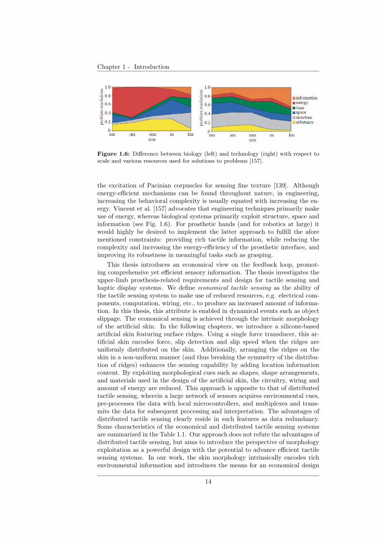
Chapter 1 - Introduction
Figure 1.6: Difference between biology (left) and technology (right) with respect toscale and various resources used for solutions to problems [157].
the excitation of Pacinian corpuscles for sensing fine texture [139]. Althoughenergy-efficient mechanisms can be found throughout nature, in engineering,increasing the behavioral complexity is usually equated with increasing the en-ergy. Vincent et al. [157] advocates that engineering techniques primarily makeuse of energy, whereas biological systems primarily exploit structure, space andinformation (see Fig. 1.6). For prosthetic hands (and for robotics at large) itwould highly be desired to implement the latter approach to fulfill the aforementioned constraints: providing rich tactile information, while reducing thecomplexity and increasing the energy-efficiency of the prosthetic interface, andimproving its robustness in meaningful tasks such as grasping.
This thesis introduces an economical view on the feedback loop, promot-ing comprehensive yet efficient sensory information. The thesis investigates theupper-limb prosthesis-related requirements and design for tactile sensing andhaptic display systems. We define economical tactile sensing as the ability ofthe tactile sensing system to make use of reduced resources, e.g. electrical com-ponents, computation, wiring, etc., to produce an increased amount of informa-tion. In this thesis, this attribute is enabled in dynamical events such as objectslippage. The economical sensing is achieved through the intrinsic morphologyof the artificial skin. In the following chapters, we introduce a silicone-basedartificial skin featuring surface ridges. Using a single force transducer, this ar-tificial skin encodes force, slip detection and slip speed when the ridges areuniformly distributed on the skin. Additionally, arranging the ridges on theskin in a non-uniform manner (and thus breaking the symmetry of the distribu-tion of ridges) enhances the sensing capability by adding location informationcontent. By exploiting morphological cues such as shapes, shape arrangements,and materials used in the design of the artificial skin, the circuitry, wiring andamount of energy are reduced. This approach is opposite to that of distributedtactile sensing, wherein a large network of sensors acquires environmental cues,pre-processes the data with local microcontrollers, and multiplexes and trans-mits the data for subsequent processing and interpretation. The advantages ofdistributed tactile sensing clearly reside in such features as data redundancy.Some characteristics of the economical and distributed tactile sensing systemsare summarized in the Table 1.1. Our approach does not refute the advantages ofdistributed tactile sensing, but aims to introduce the perspective of morphologyexploitation as a powerful design with the potential to advance efficient tactilesensing systems. In our work, the skin morphology intrinsically encodes richenvironmental information and introduces the means for an economical design
14
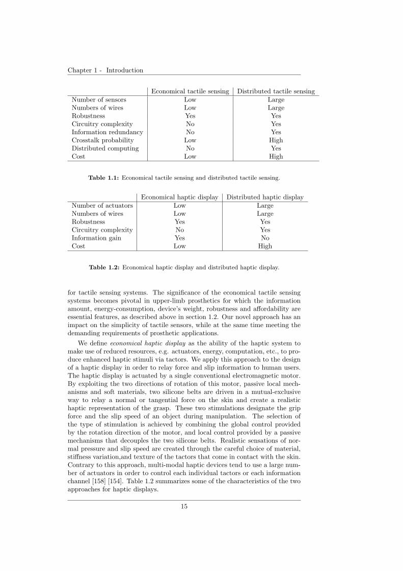
Chapter 1 - Introduction
Economical tactile sensing Distributed tactile sensingNumber of sensors Low LargeNumbers of wires Low LargeRobustness Yes YesCircuitry complexity No YesInformation redundancy No YesCrosstalk probability Low HighDistributed computing No YesCost Low High
Table 1.1: Economical tactile sensing and distributed tactile sensing.
Economical haptic display Distributed haptic displayNumber of actuators Low LargeNumbers of wires Low LargeRobustness Yes YesCircuitry complexity No YesInformation gain Yes NoCost Low High
Table 1.2: Economical haptic display and distributed haptic display.
for tactile sensing systems. The significance of the economical tactile sensingsystems becomes pivotal in upper-limb prosthetics for which the informationamount, energy-consumption, device’s weight, robustness and affordability areessential features, as described above in section 1.2. Our novel approach has animpact on the simplicity of tactile sensors, while at the same time meeting thedemanding requirements of prosthetic applications.
We define economical haptic display as the ability of the haptic system tomake use of reduced resources, e.g. actuators, energy, computation, etc., to pro-duce enhanced haptic stimuli via tactors. We apply this approach to the designof a haptic display in order to relay force and slip information to human users.The haptic display is actuated by a single conventional electromagnetic motor.By exploiting the two directions of rotation of this motor, passive local mech-anisms and soft materials, two silicone belts are driven in a mutual-exclusiveway to relay a normal or tangential force on the skin and create a realistichaptic representation of the grasp. These two stimulations designate the gripforce and the slip speed of an object during manipulation. The selection ofthe type of stimulation is achieved by combining the global control providedby the rotation direction of the motor, and local control provided by a passivemechanisms that decouples the two silicone belts. Realistic sensations of nor-mal pressure and slip speed are created through the careful choice of material,stiffness variation,and texture of the tactors that come in contact with the skin.Contrary to this approach, multi-modal haptic devices tend to use a large num-ber of actuators in order to control each individual tactors or each informationchannel [158] [154]. Table 1.2 summarizes some of the characteristics of the twoapproaches for haptic displays.
15

Chapter 1 - Introduction
1.6 Overview of the thesis
The remaining content of this thesis is organized in seven chapters, as describedin Fig. 1.7. Chapters 2 and 3 investigate the requirements pertaining a compre-hensive representation of grasp for efficient grasp stability in upper-limb prosthe-ses. Chapter 2 focuses on the role of the slip speed feedback in grasp stability.We explore the advantages of quantitative slip feedback, as a complement toexisting approaches on force feedback for haptic interfaces.
Chapter 3 studies the individual and combined benefit of force and slip speedfeedback for grasp stability. In this study, we integrate an artificial skin for forceand slip sensing with a graphical display of grip force and slip speed.
Chapters 4 and 5 introduce a ridged artificial skin, whose morphology en-ables an efficient haptic sensing in prostheses. Chapter 4 presents the artificialskin featuring linearly-distributed ridges for the detection of grip force, slipoccurrence and speed of a held object. In Chapter 5, the capabilities of theartificial skin are extended to location detection, by distributing the ridges onthe skin in a non-uniform manner.
Chapters 6, 7 and 8 investigate efficient techniques for relaying rich haptic in-formation to the prosthesis wearer through the design of haptic devices. Chapter6 presents a haptic apparatus used to study potential information transmittedby moving or by making/breaking contacts to an (artificial) skin. Chapter 7focuses on the influence of the shapes of soft tactors to generate grip force byperiodically making/breaking the contact with a surface. Chapter 8 presentsthe development and the evaluation of an efficient wearable haptic device thatis able to relay grip force and slip speed information.
Finally, this thesis is wrapped up with discussions and a conclusion in Chap-ter 9.
16
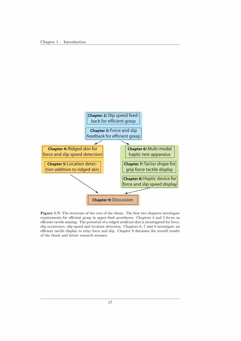
Chapter 1 - Introduction
Chapter 2: Slip speed feed-
back for efficient grasp
Chapter 3: Force and slip
feedback for efficient grasp
Chapter 4: Ridged skin for
force and slip speed detection
Chapter 5: Location detec-
tion addition to ridged skin
Chapter 6: Multi-modal
haptic test-apparatus
Chapter 7: Tactor shape for
grip force tactile display
Chapter 8: Haptic device for
force and slip speed display
Chapter 9: Discussion
Figure 1.7: The structure of the core of the thesis. The first two chapters investigaterequirements for efficient grasp in upper-limb prostheses. Chapters 4 and 5 focus onefficient tactile sensing. The potential of a ridged artificial skin is investigated for force,slip occurrence, slip speed and location detection. Chapters 6, 7 and 8 investigate anefficient tactile display to relay force and slip. Chapter 9 discusses the overall resultsof the thesis and future research avenues.
17

Chapter 1 - Introduction
18
Chapter 2
Slip Speed Feedback for
Prosthetic ApplicationsRole of slip speed feedback forgrasp stability
Chapter 2 describes a set of experiments whose results motivated further inves-tigation of slip speed feedback for efficient grasp stability.Grasp stability in the human hand has been resolved by means of an intri-cate network of mechanoreceptors integrating numerous cues about mechani-cal events, through an ontogenetic grasp practice. An engineered prostheticinterface introduces considerable perturbation risks in grasping, e.g. objectinstability, calling for feedback modalities that address the underlying slip phe-nomenon. In the present study, we propose an enhanced slip feedback modality,with potential for myoelectric-based prosthetic applications, that relays infor-mation regarding slip events, particularly slip occurrence and slip speed. Theproposed feedback modality, implemented using electrotactile stimulation, wasevaluated in psychophysical studies of slip control in a simplified setup. Theobtained results were compared with vision and a binary slip feedback thattransmits on-off information about slip detection. The slip control efficiency ofthe slip speed display is comparable to that obtained with vision feedback, andit clearly outperforms the efficiency of the on-off slip modality in such tasks.These results suggest that the proposed tactile feedback is a promising sensorymethod for the restoration of stable grasp in prosthetic applications.
1Parts of the material in this chapter previously appeared in: Dana D. Damian, AlejandroHernandez Arieta, Harold Roberto Martinez Salazar and Rolf Pfeifer (2012) “Slip SpeedFeedback for Prosthetic Applications”, IEEE Transactions on Biomedical Engineering, (inpress).
19
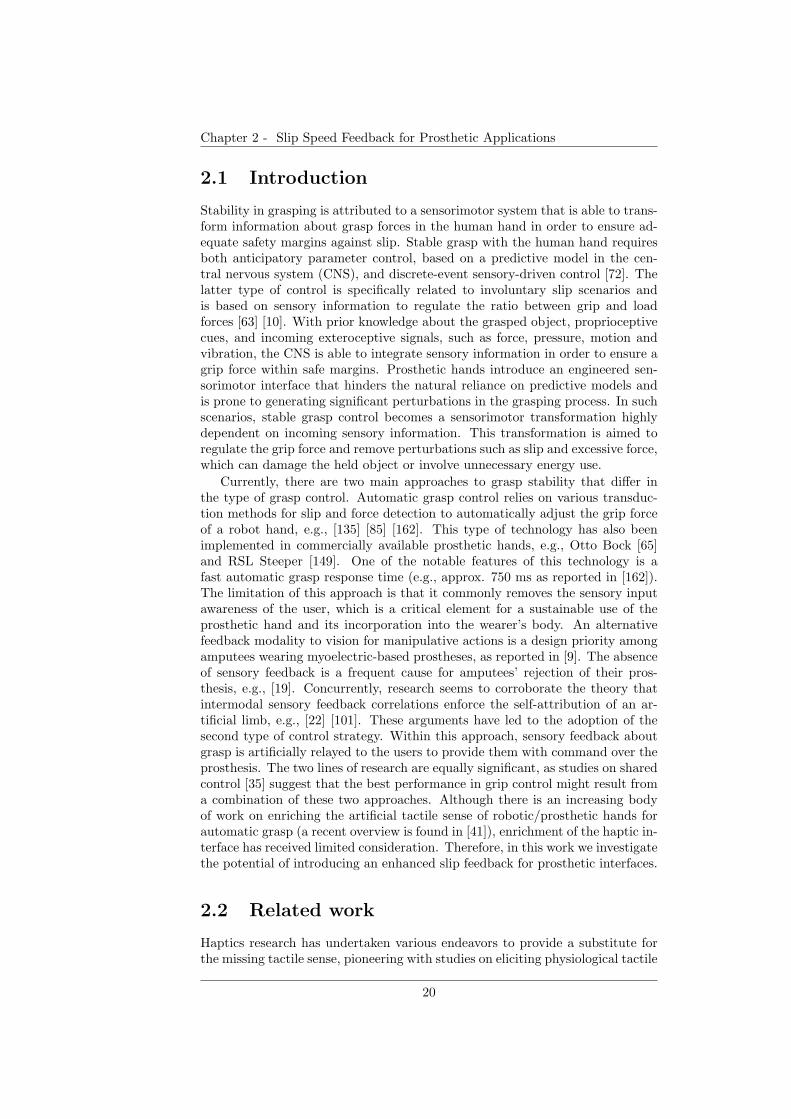
Chapter 2 - Slip Speed Feedback for Prosthetic Applications
2.1 Introduction
Stability in grasping is attributed to a sensorimotor system that is able to trans-form information about grasp forces in the human hand in order to ensure ad-equate safety margins against slip. Stable grasp with the human hand requiresboth anticipatory parameter control, based on a predictive model in the cen-tral nervous system (CNS), and discrete-event sensory-driven control [72]. Thelatter type of control is specifically related to involuntary slip scenarios andis based on sensory information to regulate the ratio between grip and loadforces [63] [10]. With prior knowledge about the grasped object, proprioceptivecues, and incoming exteroceptive signals, such as force, pressure, motion andvibration, the CNS is able to integrate sensory information in order to ensure agrip force within safe margins. Prosthetic hands introduce an engineered sen-sorimotor interface that hinders the natural reliance on predictive models andis prone to generating significant perturbations in the grasping process. In suchscenarios, stable grasp control becomes a sensorimotor transformation highlydependent on incoming sensory information. This transformation is aimed toregulate the grip force and remove perturbations such as slip and excessive force,which can damage the held object or involve unnecessary energy use.
Currently, there are two main approaches to grasp stability that differ inthe type of grasp control. Automatic grasp control relies on various transduc-tion methods for slip and force detection to automatically adjust the grip forceof a robot hand, e.g., [135] [85] [162]. This type of technology has also beenimplemented in commercially available prosthetic hands, e.g., Otto Bock [65]and RSL Steeper [149]. One of the notable features of this technology is afast automatic grasp response time (e.g., approx. 750 ms as reported in [162]).The limitation of this approach is that it commonly removes the sensory inputawareness of the user, which is a critical element for a sustainable use of theprosthetic hand and its incorporation into the wearer’s body. An alternativefeedback modality to vision for manipulative actions is a design priority amongamputees wearing myoelectric-based prostheses, as reported in [9]. The absenceof sensory feedback is a frequent cause for amputees’ rejection of their pros-thesis, e.g., [19]. Concurrently, research seems to corroborate the theory thatintermodal sensory feedback correlations enforce the self-attribution of an ar-tificial limb, e.g., [22] [101]. These arguments have led to the adoption of thesecond type of control strategy. Within this approach, sensory feedback aboutgrasp is artificially relayed to the users to provide them with command over theprosthesis. The two lines of research are equally significant, as studies on sharedcontrol [35] suggest that the best performance in grip control might result froma combination of these two approaches. Although there is an increasing bodyof work on enriching the artificial tactile sense of robotic/prosthetic hands forautomatic grasp (a recent overview is found in [41]), enrichment of the haptic in-terface has received limited consideration. Therefore, in this work we investigatethe potential of introducing an enhanced slip feedback for prosthetic interfaces.
2.2 Related work
Haptics research has undertaken various endeavors to provide a substitute forthe missing tactile sense, pioneering with studies on eliciting physiological tactile
20
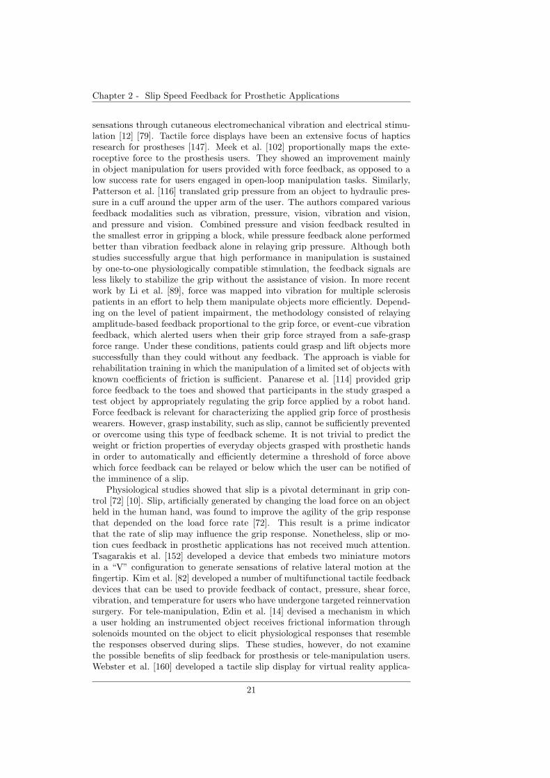
Chapter 2 - Slip Speed Feedback for Prosthetic Applications
sensations through cutaneous electromechanical vibration and electrical stimu-lation [12] [79]. Tactile force displays have been an extensive focus of hapticsresearch for prostheses [147]. Meek et al. [102] proportionally maps the exte-roceptive force to the prosthesis users. They showed an improvement mainlyin object manipulation for users provided with force feedback, as opposed to alow success rate for users engaged in open-loop manipulation tasks. Similarly,Patterson et al. [116] translated grip pressure from an object to hydraulic pres-sure in a cuff around the upper arm of the user. The authors compared variousfeedback modalities such as vibration, pressure, vision, vibration and vision,and pressure and vision. Combined pressure and vision feedback resulted inthe smallest error in gripping a block, while pressure feedback alone performedbetter than vibration feedback alone in relaying grip pressure. Although bothstudies successfully argue that high performance in manipulation is sustainedby one-to-one physiologically compatible stimulation, the feedback signals areless likely to stabilize the grip without the assistance of vision. In more recentwork by Li et al. [89], force was mapped into vibration for multiple sclerosispatients in an effort to help them manipulate objects more efficiently. Depend-ing on the level of patient impairment, the methodology consisted of relayingamplitude-based feedback proportional to the grip force, or event-cue vibrationfeedback, which alerted users when their grip force strayed from a safe-graspforce range. Under these conditions, patients could grasp and lift objects moresuccessfully than they could without any feedback. The approach is viable forrehabilitation training in which the manipulation of a limited set of objects withknown coefficients of friction is sufficient. Panarese et al. [114] provided gripforce feedback to the toes and showed that participants in the study grasped atest object by appropriately regulating the grip force applied by a robot hand.Force feedback is relevant for characterizing the applied grip force of prosthesiswearers. However, grasp instability, such as slip, cannot be sufficiently preventedor overcome using this type of feedback scheme. It is not trivial to predict theweight or friction properties of everyday objects grasped with prosthetic handsin order to automatically and efficiently determine a threshold of force abovewhich force feedback can be relayed or below which the user can be notified ofthe imminence of a slip.
Physiological studies showed that slip is a pivotal determinant in grip con-trol [72] [10]. Slip, artificially generated by changing the load force on an objectheld in the human hand, was found to improve the agility of the grip responsethat depended on the load force rate [72]. This result is a prime indicatorthat the rate of slip may influence the grip response. Nonetheless, slip or mo-tion cues feedback in prosthetic applications has not received much attention.Tsagarakis et al. [152] developed a device that embeds two miniature motorsin a “V” configuration to generate sensations of relative lateral motion at thefingertip. Kim et al. [82] developed a number of multifunctional tactile feedbackdevices that can be used to provide feedback of contact, pressure, shear force,vibration, and temperature for users who have undergone targeted reinnervationsurgery. For tele-manipulation, Edin et al. [14] devised a mechanism in whicha user holding an instrumented object receives frictional information throughsolenoids mounted on the object to elicit physiological responses that resemblethe responses observed during slips. These studies, however, do not examinethe possible benefits of slip feedback for prosthesis or tele-manipulation users.Webster et al. [160] developed a tactile slip display for virtual reality applica-
21
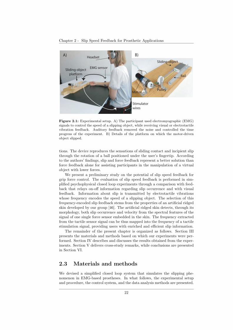
Chapter 2 - Slip Speed Feedback for Prosthetic Applications
Rail
Sliding object
PulleyMotor
B)A)
EMG sensor
Stimulator
wires
Sliding object
platform
HeadsetA)
Figure 2.1: Experimental setup. A) The participant used electromyographic (EMG)signals to control the speed of a slipping object, while receiving visual or electrotactilevibration feedback. Auditory feedback removed the noise and controlled the timeprogress of the experiment. B) Details of the platform on which the motor-drivenobject slipped.
tions. The device reproduces the sensations of sliding contact and incipient slipthrough the rotation of a ball positioned under the user’s fingertip. Accordingto the authors’ findings, slip and force feedback represent a better solution thanforce feedback alone for assisting participants in the manipulation of a virtualobject with lower forces.
We present a preliminary study on the potential of slip speed feedback forgrip force control. The evaluation of slip speed feedback is performed in sim-plified psychophysical closed loop experiments through a comparison with feed-back that relays on-off information regarding slip occurrence and with visualfeedback. Information about slip is transmitted by electrotactile vibrationswhose frequency encodes the speed of a slipping object. The selection of thisfrequency-encoded slip feedback stems from the properties of an artificial ridgedskin developed by our group [46]. The artificial ridged skin detects, through itsmorphology, both slip occurrence and velocity from the spectral features of thesignal of one single force sensor embedded in the skin. The frequency extractedfrom the tactile sensor signal can be thus mapped into the frequency of a tactilestimulation signal, providing users with enriched and efficient slip information.
The remainder of the present chapter is organized as follows. Section IIIpresents the materials and methods based on which our experiments were per-formed. Section IV describes and discusses the results obtained from the exper-iments. Section V delivers cross-study remarks, while conclusions are presentedin Section VI.
2.3 Materials and methods
We devised a simplified closed loop system that simulates the slipping phe-nomenon in EMG-based prostheses. In what follows, the experimental setupand procedure, the control system, and the data analysis methods are presented.
22
Chapter 2 - Slip Speed Feedback for Prosthetic Applications
2.3.1 Experimental setup
We opted to implement a physical experimental setup of the slip phenomenon,instead of a graphical one, in order to create a more realistic and intuitive envi-ronment for the participants of the study. Figure 2.1A depicts the experimentalsetup. A participant was seated in a relaxed position with his arm on a tablewith his palm facing upward at an angle of approximately 45 ◦. Muscle contrac-tions were acquired from the participant’s Flexor Carpi Ulnaris muscle throughone wireless electromyographic (EMG) sensor (Noraxon Inc.). The sensor sam-pled the contraction signal at 1, 500 Hz. On the table in front of the participant,an object weighing 250 g was made to slip on a horizontal surface. A pair ofrails kept the object moving in the same direction. The object was connectedto a pulley of the DC motor of 16 mm in diameter through a non-deformablewire (Fig. 2.1B). The DC motor (Faulhaber DC-Micromotor 2642), driven bya speed controller (Atmel ATmega328P AVR microcontroller), dragged the ob-ject along the platform surface at a constant velocity. The participant receivedfeedback about the slip of the object by vision or cutaneous electrotactile stim-ulation. We chose the latter type of stimulation due to its high controllabilityand long-studied characteristics [79]. An electrical stimulator, generating bipha-sic signals of tunable frequencies [143], transmitted the cutaneous stimulationthrough one pair of self-adhesive multilayer hydrogel electrodes of 5x5 cm size(PALS Neurostimulation electrodes, Axelgaard Manufacturing Co., Ltd.), thusmapping 1D information about slip. The electrodes were placed on the lumbararea of the back, symmetrically with respect to the spine. We chose this areabecause it has a low sensory load [129], and there is no crosstalk between thesignal of the electrical stimulator and the EMG signal. Detailed properties ofthese electrodes for prosthetic applications were studied in [143]. White noisewas sent constantly to the headset in order to remove potential sound patternsthat may influence the experimental process. Potential vibrations from the DCmotor were eliminated by a soft pad placed beneath the forearm of the par-ticipant. A PC collected the EMG sensor signal and, accordingly, sent controlcommands to the DC motor controller regarding the speed at which to drag theobject.
2.3.2 Experimental procedure
Nine unimpaired volunteers ranging in age from 26 to 34 years participated inthree experiments, after having read the instructions and having given theirconsent. The number of participants was computed using the G*power analysisprogram [55]. Prior to commencing the study, ethical clearance was providedby the Swiss Association of Ethics Committees (KEK).
The participants were tasked with stopping an object from slipping by con-tracting their muscle based on the sensory information received from a feedbackmodality. This closed loop simulated the control of an EMG-driven prosthetichand, the grip closure of which is regulated proportionally with respect to theuser-dependent intensity of the EMG input signal over a fixed time period [53].Consequently, the grip closure affects the slip or slip velocity of a held object.Hence, a weak grip closure allows an object to slip, and a strong grip maycrush the object. However, an optimum hand closure can stop the object fromslipping. The participants were instructed to contract their muscles without
23
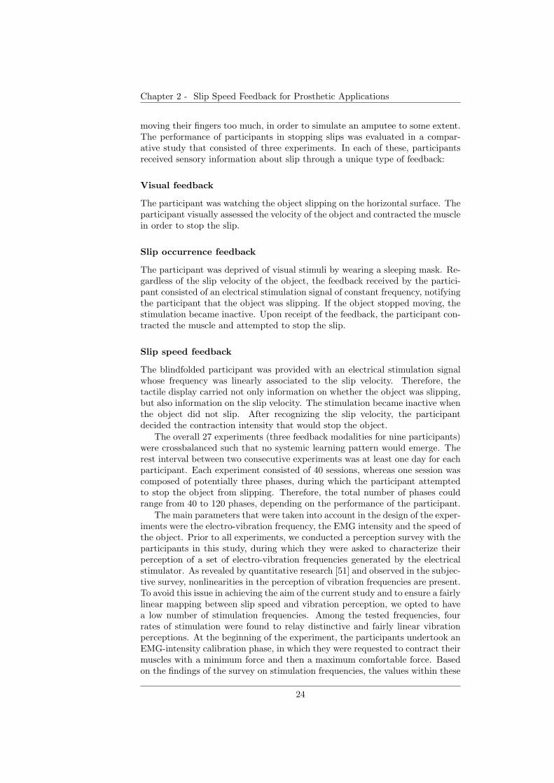
Chapter 2 - Slip Speed Feedback for Prosthetic Applications
moving their fingers too much, in order to simulate an amputee to some extent.The performance of participants in stopping slips was evaluated in a compar-ative study that consisted of three experiments. In each of these, participantsreceived sensory information about slip through a unique type of feedback:
Visual feedback
The participant was watching the object slipping on the horizontal surface. Theparticipant visually assessed the velocity of the object and contracted the musclein order to stop the slip.
Slip occurrence feedback
The participant was deprived of visual stimuli by wearing a sleeping mask. Re-gardless of the slip velocity of the object, the feedback received by the partici-pant consisted of an electrical stimulation signal of constant frequency, notifyingthe participant that the object was slipping. If the object stopped moving, thestimulation became inactive. Upon receipt of the feedback, the participant con-tracted the muscle and attempted to stop the slip.
Slip speed feedback
The blindfolded participant was provided with an electrical stimulation signalwhose frequency was linearly associated to the slip velocity. Therefore, thetactile display carried not only information on whether the object was slipping,but also information on the slip velocity. The stimulation became inactive whenthe object did not slip. After recognizing the slip velocity, the participantdecided the contraction intensity that would stop the object.
The overall 27 experiments (three feedback modalities for nine participants)were crossbalanced such that no systemic learning pattern would emerge. Therest interval between two consecutive experiments was at least one day for eachparticipant. Each experiment consisted of 40 sessions, whereas one session wascomposed of potentially three phases, during which the participant attemptedto stop the object from slipping. Therefore, the total number of phases couldrange from 40 to 120 phases, depending on the performance of the participant.
The main parameters that were taken into account in the design of the exper-iments were the electro-vibration frequency, the EMG intensity and the speed ofthe object. Prior to all experiments, we conducted a perception survey with theparticipants in this study, during which they were asked to characterize theirperception of a set of electro-vibration frequencies generated by the electricalstimulator. As revealed by quantitative research [51] and observed in the subjec-tive survey, nonlinearities in the perception of vibration frequencies are present.To avoid this issue in achieving the aim of the current study and to ensure a fairlylinear mapping between slip speed and vibration perception, we opted to havea low number of stimulation frequencies. Among the tested frequencies, fourrates of stimulation were found to relay distinctive and fairly linear vibrationperceptions. At the beginning of the experiment, the participants undertook anEMG-intensity calibration phase, in which they were requested to contract theirmuscles with a minimum force and then a maximum comfortable force. Basedon the findings of the survey on stimulation frequencies, the values within these
24
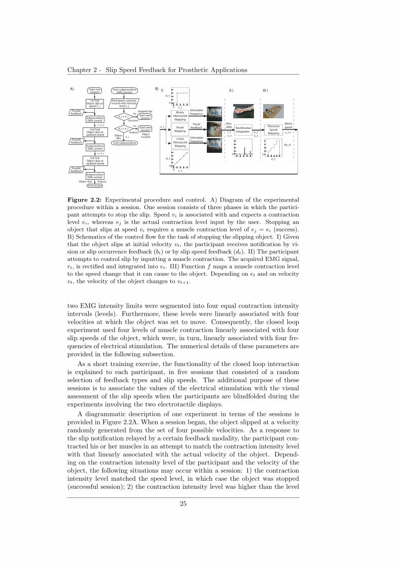
Chapter 2 - Slip Speed Feedback for Prosthetic Applications
Start new session
1st TrialObject slips at
speed v_i
SubprocedureEMG control
2nd TrialObject slips at
updated speed
Provide feedback
SubprocedureEMG control
3rd TrialObject slips at
updated speed
Provide feedback
SubprocedureEMG control
Provide feedback
End session
(Failure)
Participant contracts muscle with intensity
level e_j
Start subprocedureEMG control
e_j = e_i
e_j > e_i
Start new session
Start new session
End subprocedure
(Success)
(Failure)
e_j
v_i, e_j
v_i, e_j
Yes
Yes
Binary
Vibrotactile
Mapping
Stimulator
frequency
Linear
Vibrotactile
Mapping
Stimulator
frequency
Visual
Mapping
Visual
feedback
0
0
I)
d_t
Raw
EMG Rectification
Integration
Piecewise
Speed
Mapping
Motor
speed
0 0
r_t
v_t e_t
v_t
f(e_t)
v_t+1
v_t
e_t
0
0
b_t
v_t
v_t
II ) III )A) B)
Stopped slip
Object crushed
Objectslips
Object slips
Figure 2.2: Experimental procedure and control. A) Diagram of the experimentalprocedure within a session. One session consists of three phases in which the partici-pant attempts to stop the slip. Speed vi is associated with and expects a contractionlevel ei, whereas ej is the actual contraction level input by the user. Stopping anobject that slips at speed vi requires a muscle contraction level of ej = ei (success).B) Schematics of the control flow for the task of stopping the slipping object. I) Giventhat the object slips at initial velocity vt, the participant receives notification by vi-sion or slip occurrence feedback (bt) or by slip speed feedback (dt). II) The participantattempts to control slip by inputting a muscle contraction. The acquired EMG signal,rt, is rectified and integrated into et. III) Function f maps a muscle contraction levelto the speed change that it can cause to the object. Depending on et and on velocityvt, the velocity of the object changes to vt+1.
two EMG intensity limits were segmented into four equal contraction intensityintervals (levels). Furthermore, these levels were linearly associated with fourvelocities at which the object was set to move. Consequently, the closed loopexperiment used four levels of muscle contraction linearly associated with fourslip speeds of the object, which were, in turn, linearly associated with four fre-quencies of electrical stimulation. The numerical details of these parameters areprovided in the following subsection.
As a short training exercise, the functionality of the closed loop interactionis explained to each participant, in five sessions that consisted of a randomselection of feedback types and slip speeds. The additional purpose of thesesessions is to associate the values of the electrical stimulation with the visualassessment of the slip speeds when the participants are blindfolded during theexperiments involving the two electrotactile displays.
A diagrammatic description of one experiment in terms of the sessions isprovided in Figure 2.2A. When a session began, the object slipped at a velocityrandomly generated from the set of four possible velocities. As a response tothe slip notification relayed by a certain feedback modality, the participant con-tracted his or her muscles in an attempt to match the contraction intensity levelwith that linearly associated with the actual velocity of the object. Depend-ing on the contraction intensity level of the participant and the velocity of theobject, the following situations may occur within a session: 1) the contractionintensity level matched the speed level, in which case the object was stopped(successful session); 2) the contraction intensity level was higher than the level
25
Chapter 2 - Slip Speed Feedback for Prosthetic Applications
corresponding to the actual speed, in which case the object was assumed to becrushed (failed session); and 3) the contraction intensity level was lower thanthe level corresponding to the actual speed, in which case the object contin-ued to slip at a reduced speed (the session proceeds to the next phase). Themovement velocity of the object, altered by the input contraction intensity level,was updated at the beginning of each subsequent phase. The following subsec-tion contains further details about the control of the experimental procedure.In addition to the slip feedback, the participants received auditory cues thatcontrol the course of the experiment and also informed participants regardingtheir performance. The auditory cues denoted the beginning of a session/phase,instructing participants of when to contract their muscles, and notified the par-ticipants of successes or failures in stopping the slipping object at the end ofa session. One phase lasted four seconds, while the pause between phases wasone second. Approximately five seconds elapsed between consecutive sessions,which was necessary to manually relocate the object at the starting positionfor the experiment with visual feedback. The four-second interval for responsetime was chosen to ease the participants’ task by providing a relatively largeamount of time to assess slip velocity and react to it. Although in natural-object manipulation, muscle contraction continuously modulates the state ofthe slipping object, participants of this study could relax their muscles duringthe inter-phase pause. The procedure was justified by measures to avoid mus-cle exhaustion along a minimum of 40 contraction phases. The procedure canalso be thought of as describing an artificial interface between muscle activityand the prosthesis controller that offers large freedom in the design of a sharedcontrol scheme for manipulation.
2.3.3 Control system
The control system coordinating the phases of the experiment was implementedon a PC and is depicted in Fig. 2.2B. In an experimental phase, an object wasmade to slip at one of four rates 1.8, 3.2, 4.6, or 6.0 mm/s. These rates are in theset V = {vi}, i ∈ 1 : 4. The relation between the rates is vj = vi − 1.4 · (i− j),where i, j ∈ 1 : 4. The four specific values were chosen to comply with the spaceconstraints of the experimental platform and with the session time requirementsof the experimental procedure. Slip information was relayed to the participantseither by visual feedback or by electrotactile feedback (Fig. 2.2B.I). For experi-ments with electrotactile feedback, the cutaneous vibration frequencies selectedin the preliminary survey are in the set H = {4, 36, 68, 100} Hz. In particular,slip occurrence feedback at time t was defined as a piecewise function:
bt =
{
fb : vt 6= 00 : vt = 0
with fb = 68 Hz ⊂ H for all participants. This stimulation frequency wasextracted from the empirical frequency set as a value close to the median of theset. Essentially, this modality is confined to only conveying feedback messageson whether slip occurred. In case the object was slipping (speed vt 6= 0),the stimulator transmits one frequency signal, fb, otherwise the stimulation isinactive. The slip speed feedback at time t was designated by a discrete linearmapping, dt = ld(vt) ⊂ H, and contains frequency-encoded information aboutabsolute values of the slip velocities. Based on the values of the experimental
26
Chapter 2 - Slip Speed Feedback for Prosthetic Applications
velocities and vibration frequencies, the linear function ld = 22.85 · vt − 37.14was derived. Thus, low vibration frequencies correspond to low slip velocities,and high vibration frequencies correspond to high slip velocities. The interceptfactor, −37.14, is a consequence of the empirical linear design of the slip speedfeedback function.
As mentioned previously, at the beginning of an experiment, the minimum,emin, and the maximum comfortable contraction, emax, were stored. The valueswithin these two limits were segmented into four equal contraction intensityintervals (levels) corresponding to the four possible velocities of a slipping object.We denoted the set of EMG intensity levels as E = {ej}, j ∈ 0 : 5, where weincluded level e0 for the case of an input intensity below emin and level e5 in orderto represent the input intensity above emax. Within each experimental phase,as a response to the slip information received, the raw EMG signal, r, acquiredfrom the muscle contraction, was rectified, and its integral was computed inorder to obtain the EMG intensity ej (Fig. 2.2B.II).
The participant could alter the slip velocity of the object by contractingthe muscle at a relevant intensity level, ej > emin. The piecewise functionf : E → V ∪ {0,∞} maps the contraction intensity level to the velocity changethat it can cause (Fig. 2.2B.III):
f(ej) =
vi : j ∈ 1 : 4 ∧ i = j0 : j = 0∞ : j = 5
Depending on the current slip velocity vt = vi ∈ V and the contraction intensitylevel et = ej ∈ E, the new speed assigned to the object is given by the relation:
vt+1 =
{
vt − f(et) : f(et) ≤ vt (1)0 : f(et) > vt (2)
where vt+1 : V → V ∪ {0}. If vt+1 = 0, the object is stopped (vt+1 = 0 mm/s),and the session finishes as a success (condition (1) with f(et) = vt) or failure(condition (2)). Otherwise, the object continues to slip at a lower velocity(condition (1) with et > emin) or at the same velocity (condition (1) withet = emin). The new speed, vt+1 is updated in the subsequent phase. If after allthree phases, vt+1 6= 0, then the session finishes as a failure. For example, if thecurrent speed of the object is vt = v4 = 6.0 mm/s and the muscle contractionlevel is e3 (the value is user-dependent), then the speed in the following phase(if the current phase is not the last phase) is vt+1 = v4 − v3 = 6.0 − 3 · 1.4 =1.8 mm/s= v1.
2.3.4 Data analysis
The data obtained in the experiments was stored in files and included the rawEMG signal of the participant, indexes for sessions and phases, the expectedmuscle contraction level corresponding to the slip speed of the object, the ac-tual muscle contraction level of the participant, and the EMG intensity perphase. Comparison of the three different feedback modalities requires severalperformance measurements to be derived and applied to the data:
27
Chapter 2 - Slip Speed Feedback for Prosthetic Applications
Promptness to stop slip
Success refers to a session in which the participants are able to stop the object,i.e., the participants respond with a muscle contraction level that correspondsto the given slip velocity of the object. In contrast, failure refers to a sessionin which: 1) the slip speed was not altered because the contraction level wasbelow the minimum contraction value or 2) the slip speed was only decreased asa result of insufficient muscle contraction or 3) the slip was stopped at the costof “crushing” the object due to excessive muscle contraction. One of the perfor-mance measures in the present study is the promptness to overcome slip, i.e.,how many attempts (phases) participants needed to stop the object. The defi-nition may be pertinent to prosthetic interfaces that are predominantly coarsecompared to the dexterity of the human hand. The most prompt response char-acterizes a session in which slip was overcome from the first phase, whereas theleast prompt response stands for a session in which the moving object was notstopped in any of the three given phases. For each of the three feedback modal-ities, the following variables were quantified: the percentages of successes in thefirst phase, the second phase, and the third phase, as well as the percentage offailures to stop the object within the three phases.
Success-to-EMG-intensity ratio
The success-to-EMG-intensity ratio provides a measure of profit from the feed-back modality, taking into consideration both success and the expense in effort(EMG input). Success refers to the percentage of success in stopping the slip ofthe object within an experiment (across all sessions). The EMG signal intensityaccounted for the effort of the participant to overcome the slip of the object dur-ing a session. The EMG intensity within a phase, denoted as e, was computedwith respect to the emin and emax contraction intensities, after having rectifiedand integrated the EMG input signal. Subsequently, the average EMG intensityinvested per session by a participant is designated by the following value
IEMG =1
N·
T∑
i=1
e(i)− emin
emax − emin
where N represents the total number of sessions, and T represents the totalnumber of phases ranging from 40 to 120.
Hence, the success-to-EMG-intensity ratio of a participant becomes:
P =
∑N
i=1 success(i)%
IEMG
(2.1)
Contraction level deviation
The contraction level deviation measured the degree of variability in the inputcontraction levels with respect to the expected contraction level. The types ofcontraction variation are described by the matrix S in Fig. 2.5A. We computedthe joint probability distribution matrix, p(ej , vi), with ej ∈ E, vi ∈ V , for aparticipant, to which we further applied the mask matrix S : E×V → {L1..L9}.The contraction level deviation, D(k) ∈ R with k ∈ {L1..L9}, was thus derived
28
Chapter 2 - Slip Speed Feedback for Prosthetic Applications
as:
D(k) =
∑
i,j;S(ej ,vi)=k p(ej , vi)∑
i,j;S(ej ,vi)=k 1, (2.2)
where the numerator represents the total number of instances of Lk-type con-tractions exerted by the participant, while the denominator is a normalizationfactor representing the total number of Lk-type contractions appearing in themask matrix.
Reaction time within a phase
We examined participants’ reaction time to slip, within a phase, in order topresent considerations for the design of “human-in-the-loop” control interfaces.It is worth noting that the reaction time to slip within a phase was not a controlparameter in the design of our experiments, thus participants did not regulate itfor best performance. Therefore, the response time provides only an indicationof an unconstrained time standard for voluntary reaction to a tactile stimulus.We computed the reaction time to slip as the duration between the onset of aphase and the rise of the EMG signal above a threshold of 90% of the EMGsignal amplitude corresponding to the lowest slip speed.
2.4 Results and Discussion
In this section we provide statistical evidence about the efficiency of the threefeedback modalities.
2.4.1 Promptness to stop slip
In the present study, we investigate how quickly, in terms of phases, the userscan stop an object from slipping, depending on the feedback modality and theslip velocity of the object. Figure 2.3A shows the results for the nine partic-ipants for the case in which the speed of the slipping object was 1.8 mm/s.Single factor analysis of variance (ANOVA) for three levels corresponding tothe three feedback modalities showed a similarity in performance in the firstand the third phases, regardless of the feedback type. Discriminatory effectsdepending on the feedback appeared only in the second phase, as confirmedby F (2, 24) = 3.77 and p < 0.05. The result shows that the visual feedbackand the slip speed feedback led to a higher rate of success relative to the slipoccurrence feedback in the second phase. At a slip velocity of 3.2 mm/s, thefeedback modality did not generally play a significant role in the first phases,as illustrated in Fig. 2.3B. However, in the third phase of a session, the par-ticipants receiving vision and slip speed feedback achieve better performancein stopping the slip of the object before the session finishes. The single factorANOVA with three levels yielded F (2, 24) = 8.80 and p < 0.01. As the slip ve-locity increased, the feedback modality imposed a gradually higher discrepancyon the performance of the participants. Identical analysis (ANOVA) for perfor-mances recorded at a slip velocity of 4.6 mm/s, indicated, by F (2, 24) = 4.45and p < 0.05, that in the second phase feedback has a discriminative effecton the performance (Fig. 2.3C). In particular, the slip speed feedback and vi-sion yielded improved results for the users. The significance of the feedback
29
Chapter 2 - Slip Speed Feedback for Prosthetic Applications
modality became even higher for a high slip velocity (Fig. 2.3D). In the firstphase of the session, at a slip velocity of 6.0 mm/s, it was far more likely thatparticipants receiving slip speed feedback were able to stop the object. Thesame analysis of variance yielded F (2, 24) = 10.37 and p < 0.001. A simpleregression was conducted in order to determine the performance of the partic-ipants in the first phase at a higher speed of slip. For each participant, we fita regression curve (a polynomial of degree less than three) to the percentage ofsuccess versus slip speed (the goodness of the fit was R2 > 0.95). Based on thefitted curve, we computed the performance of each participant at a slip velocityof 7.4 mm/s. The results, F (1, 10) = 5.57 and p < 0.05, provided by ANOVAwith two levels, revealed that the slip occurrence modality, opposite to the slipspeed feedback, would not support a prompt response to slip. Another measurerelevant to promptness is the percentage of failures to stop the slip within thefirst three phases. A feedback modality that endorses promptness should de-crease the number of such failures. At first three slip velocities, differences inthe effect of the feedback modalities were not present. However, at a slip veloc-ity of 6.0 mm/s, failures to stop the object within the first three phases wereconsiderably more frequent with the slip occurrence feedback than with the slipspeed feedback: F (1, 16) = 20.81 and p < 0.001 (ANOVA with two levels). Weperformed a regression analysis to investigate if this discrepancy maintains asthe slip velocity becomes higher. For each participant, we fit a regression curve(a polynomial of degree less than three) to the percentage of failures to stopthe object within the first three phases versus slip speed (the goodness of thefit was R− square > 0.95). Based on the fitted curve, we computed the degreeof failure to stop the object within the first three phases at a slip velocity of7.4 mm/s. At a speed higher than 6.0 mm/s, ANOVA identified the slip occur-rence feedback as the worse modality: F (2, 21) = 7.37 and p < 0.01 in case ofthe ANOVA with three levels, and F (1, 14) = 25.02 and p < 0.001 in case of theANOVA with two levels (slip occurrence and slip speed feedback). These resultssuggest that, as the speed of slip increases, the rate of failure to stop the slipwithin the first three phases drastically increases (and consequently the prompt-ness decreases) with slip occurrence feedback, as opposed to the rate of failurewith vision or the slip speed feedback. We therefore predict that discrepanciesbetween the slip speed and the slip occurrence types of feedback will escalateas the slip velocity becomes larger. The absolute values of the percentages ofsuccess were generally not high. The explanation may reside in the design of theexperimental procedure. The three-phases session limit and six-input optionslead to a 0.5 probability of stopping slip within a session. However, on a relativescale, the slip speed feedback yielded comparable or better results than vision.As indicated by the results of the present study, slip speed feedback favors arelatively more prompt response of the users in their attempt to overcome slipat an early stage.
2.4.2 Success-to-EMG-intensity ratio
For each feedback modality and each slip velocity, we computed the success-to-EMG-intensity ratio, as an indicator of the user’s profit from the feedback incontrolling the slip with an EMG-based prosthesis. The results obtained afterhaving applied Eq. 2.1 to each participant, are shown in Fig. 2.4. The typeof feedback modality provided to the user became critical as the slip velocity
30
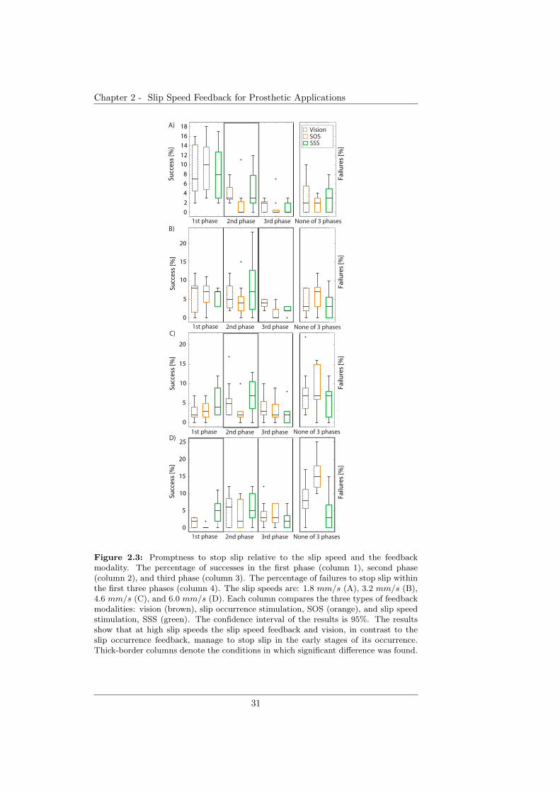
Chapter 2 - Slip Speed Feedback for Prosthetic Applications
None of 3 trials
None of 3 trials
None of 3 trials
None of 3 trials
Failu
res
[%]
Failu
res
[%]
Failu
res
[%]
Failu
res
[%]
0
2
4
6
8
10
12
14
16
18
Succ
ess
[%]
VisionSOSSSS
0
5
10
15
20
Succ
ess
[%]
1st trial 2nd trial 3rd trial
0
5
10
15
20
Succ
ess
[%]
1st trial 2nd trial 3rd trial
0
5
10
15
20
25
Succ
ess
[%]
1st phase 2nd phase 3rd phase
A)
B)
C)
D)
1st phase 2nd phase 3rd phase
1st phase 2nd phase 3rd phase
1st phase 2nd phase 3rd phase
None of 3 phases
None of 3 phases
None of 3 phases
None of 3 phases
Failu
res
[%]
Failu
res
[%]
Failu
res
[%]
Failu
res
[%]
Figure 2.3: Promptness to stop slip relative to the slip speed and the feedbackmodality. The percentage of successes in the first phase (column 1), second phase(column 2), and third phase (column 3). The percentage of failures to stop slip withinthe first three phases (column 4). The slip speeds are: 1.8 mm/s (A), 3.2 mm/s (B),4.6 mm/s (C), and 6.0 mm/s (D). Each column compares the three types of feedbackmodalities: vision (brown), slip occurrence stimulation, SOS (orange), and slip speedstimulation, SSS (green). The confidence interval of the results is 95%. The resultsshow that at high slip speeds the slip speed feedback and vision, in contrast to theslip occurrence feedback, manage to stop slip in the early stages of its occurrence.Thick-border columns denote the conditions in which significant difference was found.
31
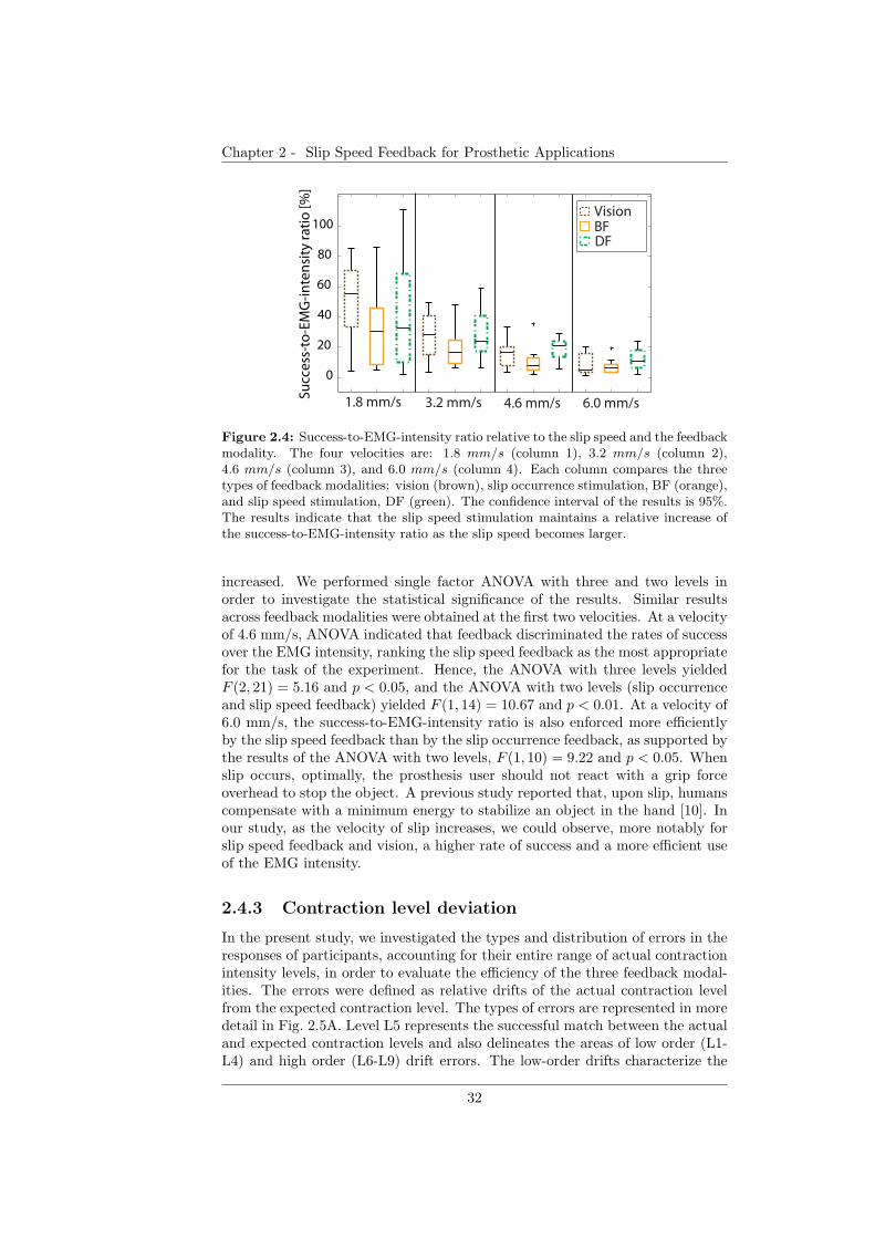
Chapter 2 - Slip Speed Feedback for Prosthetic Applications
0
20
40
60
80
100
Succ
ess
-to
-EM
G-i
nte
nsi
ty r
atio
[%]
1.8 mm/s 3.2 mm/s 4.6 mm/s 6.0 mm/s
VisionBFDF
Figure 2.4: Success-to-EMG-intensity ratio relative to the slip speed and the feedbackmodality. The four velocities are: 1.8 mm/s (column 1), 3.2 mm/s (column 2),4.6 mm/s (column 3), and 6.0 mm/s (column 4). Each column compares the threetypes of feedback modalities: vision (brown), slip occurrence stimulation, BF (orange),and slip speed stimulation, DF (green). The confidence interval of the results is 95%.The results indicate that the slip speed stimulation maintains a relative increase ofthe success-to-EMG-intensity ratio as the slip speed becomes larger.
increased. We performed single factor ANOVA with three and two levels inorder to investigate the statistical significance of the results. Similar resultsacross feedback modalities were obtained at the first two velocities. At a velocityof 4.6 mm/s, ANOVA indicated that feedback discriminated the rates of successover the EMG intensity, ranking the slip speed feedback as the most appropriatefor the task of the experiment. Hence, the ANOVA with three levels yieldedF (2, 21) = 5.16 and p < 0.05, and the ANOVA with two levels (slip occurrenceand slip speed feedback) yielded F (1, 14) = 10.67 and p < 0.01. At a velocity of6.0 mm/s, the success-to-EMG-intensity ratio is also enforced more efficientlyby the slip speed feedback than by the slip occurrence feedback, as supported bythe results of the ANOVA with two levels, F (1, 10) = 9.22 and p < 0.05. Whenslip occurs, optimally, the prosthesis user should not react with a grip forceoverhead to stop the object. A previous study reported that, upon slip, humanscompensate with a minimum energy to stabilize an object in the hand [10]. Inour study, as the velocity of slip increases, we could observe, more notably forslip speed feedback and vision, a higher rate of success and a more efficient useof the EMG intensity.
2.4.3 Contraction level deviation
In the present study, we investigated the types and distribution of errors in theresponses of participants, accounting for their entire range of actual contractionintensity levels, in order to evaluate the efficiency of the three feedback modal-ities. The errors were defined as relative drifts of the actual contraction levelfrom the expected contraction level. The types of errors are represented in moredetail in Fig. 2.5A. Level L5 represents the successful match between the actualand expected contraction levels and also delineates the areas of low order (L1-L4) and high order (L6-L9) drift errors. The low-order drifts characterize the
32
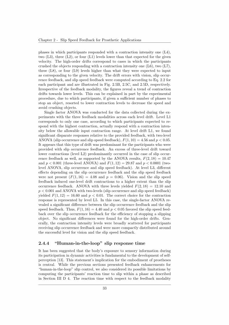
Chapter 2 - Slip Speed Feedback for Prosthetic Applications
phases in which participants responded with a contraction intensity one (L4),two (L3), three (L2), or four (L1) levels lower than that expected for the givenvelocity. The high-order drifts correspond to cases in which the participantscrushed the objects responding with a contraction intensity one (L6), two (L7),three (L8), or four (L9) levels higher than what they were expected to inputas corresponding to the given velocity. The drift errors with vision, slip occur-rence feedback, and slip speed feedback were computed according to Eq. 2.2 foreach participant and are illustrated in Fig. 2.5B, 2.5C, and 2.5D, respectively.Irrespective of the feedback modality, the figures reveal a trend of contractiondrifts towards lower levels. This can be explained in part by the experimentalprocedure, due to which participants, if given a sufficient number of phases tostop an object, resorted to lower contraction levels to decrease the speed andavoid crushing objects.
Single factor ANOVA was conducted for the data collected during the ex-periments with the three feedback modalities across each level drift. Level L1corresponds to only one case, according to which participants expected to re-spond with the highest contraction, actually respond with a contraction inten-sity below the allowable input contraction range. At level drift L1, we foundsignificant disparate responses relative to the provided feedback, with two-levelANOVA (slip occurrence and slip speed feedback), F (1, 10) = 4.56 and p < 0.05.It appears that this type of drift was predominant for the participants who wereprovided with slip occurrence feedback. An excess of three-level drift towardlower contractions (level L2) predominantly occurred in the case of slip occur-rence feedback as well, as supported by the ANOVA results, F (2, 18) = 10.47and p < 0.001 (three-level ANOVA) and F (1, 12) = 29.87 and p < 0.0001 (two-level ANOVA, slip occurrence and slip speed feedback). At level L3, differenteffects depending on the slip occurrence feedback and the slip speed feedbackwere not present (F (1, 16) = 4.08 and p = 0.06). Vision and the slip speedfeedback induced one-level drift contractions to a higher extent than the slipoccurrence feedback. ANOVA with three levels yielded F (2, 18) = 12.10 andp < 0.001 and ANOVA with two-levels (slip occurrence and slip speed feedback)yielded F (1, 12) = 16.60 and p < 0.01. The correct choice for the contractionresponse is represented by level L5. In this case, the single-factor ANOVA re-vealed a significant difference between the slip occurrence feedback and the slipspeed feedback. Thus, F (1, 16) = 4.40 and p < 0.05 favored the slip speed feed-back over the slip occurrence feedback for the efficiency of stopping a slippingobject. No significant differences were found for the high-order drifts. Gen-erally, the contraction intensity levels were broadly scattered for participantsreceiving slip occurrence feedback and were more compactly distributed aroundthe successful level for vision and the slip speed feedback.
2.4.4 “Human-in-the-loop” slip response time
It has been suggested that the body’s exposure to sensory information duringits participation in dynamic activities is fundamental to the development of self-perception [13]. This statement’s implication for the embodiment of prosthesesis central. While the previous sections presented feedback enhancements for“human-in-the-loop” slip control, we also considered its possible limitations bycomputing the participants’ reaction time to slip within a phase as describedin Section III D 4. The reaction time with respect to the feedback modality
33
Chapter 2 - Slip Speed Feedback for Prosthetic Applications
0
5
10
15
0
5
10
15
L1 L2 L3 L4 L5 L6 L7 L8 L90
5
10
15
B)
C)
D)
Nu
mb
er
of
con
trac
tio
ns
[%]
v1v2v3v4
L4 L5 L6 L7 L8 L9 L3 L4 L5 L6 L7 L8 L2 L3 L4 L5 L6 L7 L1 L2 L3 L4 L5 L6 e0 e1 e2 e3 e4 e5
A)
L1 L2 L3 L4 L5 L6 L7 L8 L9
L1 L2 L3 L4 L5 L6 L7 L8 L9
L1
Figure 2.5: Level drifts of contraction intensity. A) Mask matrix for computing leveldrifts of contraction intensity based on the presented slip speed, v, and the actualcontraction intensity level, e. Level L5 indicates the equality between the expected andthe actual level of contraction intensity. The number of contractions (as a percentage)corresponding to each level drift for visual feedback (B), slip occurrence feedback (C),and slip speed feedback (D). The confidence interval of the results is 95%. The plotsshow that the slip speed feedback and vision, compared to the slip occurrence feedback,reduce the variation of muscle contraction input.
regardless of the slip speed is presented in Fig. 2.6A. The means of the reactiontime were 1.71, 1.51, and 1.75 s with vision, slip occurrence feedback and slip
34

Chapter 2 - Slip Speed Feedback for Prosthetic Applications
speed feedback, respectively. We applied a Kruskal-Wallis non-parametric testto the reaction time of all participants across the three feedback modalities.The test yielded H(2) = 68.56 and p < 0.001 by Chi-Square. We assumed thatparticipants reacted faster when they received slip occurrence feedback becauseslip speed recognition was bypassed due to the lack of such information. Thereaction time with respect to slip speed regardless of the feedback modality ispresented in Fig. 2.6B. The means of the reaction time were 1.60, 1.64, 1.71,and 1.75 s for the set of speeds, respectively. The Kruskal-Wallis test yieldedH(3) = 21.90 and p < 0.001 by Chi-Square. In general, the reaction timewas the fastest when the slip speed was the slowest. A possible explanationstemming from our observations is that participants could easily recognize thesmallest stimulus level and control its corresponding contraction level.
1
2
3
4
Re
acti
on
tim
e [s
]
All feedback modalitiesB)
Vision BF DF0
1
2
3
4
Re
acti
on
tim
e [s
]
All speeds
0
A)
1.8 mm/s 3.2 mm/s 4.6 mm/s 6.0 mm/s
Figure 2.6: Reaction time to slip. A. Reaction time relative to the feedback modality(vision, slip occurrence feedback (BF) and slip speed feedback (DF)). B. Reaction timerelative to the slip speed. On average, the reaction time to slip was in the range of1.51 − 1.75 s for all three feedback modalities and four slip speeds. The confidenceinterval of the results is 95%.
If we consider the average reaction time extremes of 1.51 s and 1.75 s, theslip of an object traveling at the maximum experimental speed of 6 mm/s canbe stopped after a minimum distance of approximately 9 mm and 10.5 mm,respectively. Assuming a robot hand skin of length 80 mm (a regular size tocover the palm of a prosthetic hand), the two average reaction time extremes willbe able to stop the slip of an object traveling at speeds of maximum 53 mm/sand 45 mm/s, respectively. These calculations ignored various factors that canaffect slip control, such as the size and initial position of the object, the type of
35

Chapter 2 - Slip Speed Feedback for Prosthetic Applications
grip (power, precision, etc.), the time to actuate a prosthetic hand, etc. Based onthese results, we envision a hybrid control scheme for overcoming slip such thatexcessively high speeds of the slipping object are managed by local controllersof a prosthetic hand, whereas slower speeds are relayed to and managed bythe prosthesis wearer. The benefits of this control scheme are twofold: (1) itenables automatic grasp control when the user’s reaction time is slow or whenthere are technological limitations in the interface communication speed, and(2) it involves the user in the control loop, which is a sensorimotor prerequisitefor a prosthesis embodiment.
2.5 General Remarks
Our study investigated the role of slip speed feedback for grasp stability withpotential for prosthetic applications. General characteristics of the slip speedfeedback include (1) quantitative information about slip events and (2) intu-itiveness, through mapping speed to frequency, as opposed to sensory interfacesthat require users to learn various stimulation patterns. Comparative perfor-mances of slip speed feedback and vision open up the possibility of dedicatingvision to more suitable tasks.
A dexterous embodied prosthetic system may be developed by improvingthe control with slip speed feedback and by implementing a complementaryautonomous controller that manages excessively high slip speeds. The improve-ment of user performance may be achieved with vision and the slip speed feed-back by providing comprehensive training to users. In contrast, training withslip occurrence feedback could lead to limited or no improvement due to thelack of relayed information. In our study, learning did not take place for anyfeedback modality, probably because the training was only introductory andthe experiments were short. We quantified learning by splitting the series of40 consecutive sessions into two halves for each participant and computing thesuccess percentage for each half. We applied a two-way ANOVA with replica-tion, taking as factors the feedback modality and the time-dependent halves,across all participants. ANOVA yielded F (2, 48) = 3.26 and p < 0.05 for thefeedback factor, F (1, 48) = 1.37 and p = 0.24 for the two groups of sessions,and F (2, 48) = 0.21 and p = 0.80 for the interaction effect between the two fac-tors. These results indicate that although feedback modality influences successin stopping slip, there is no significant difference in the success ratio in time,and thus no learning effect occurred.
We may argue that an appropriate scheme to overcome slip of an object is toalways input low contraction intensity levels and gradually decrease the speedof the object until the object stops. In which case, slip occurrence feedbackshould be sufficient. This hypothesis was rejected based on the experimentalresults, according to which, even when confronted with the lowest contractionlevel expectation, the participants receiving slip occurrence feedback recordedthe highest percentage of crushes (8.89%, on average) relative to the other twofeedbacks (in average, 4.98% for slip speed feedback and 2.81% for vision). Asingle-factor ANOVA with three levels comparing the three feedbacks yieldedF (2, 24) = 6.62 and p < 0.01. Besides this result, the number of crushes wasnot significantly different across the slip occurrence and the slip speed feedbackmodalities, regardless of the slip speed.
36
Chapter 2 - Slip Speed Feedback for Prosthetic Applications
Using the tactile display for practical applications entails a subsequent studyof the feasibility range of the proposed feedback. This study is a prospectiveresearch avenue for our group. The setup must include a gripper with adequatesensors and must be evaluated in real-world grasp scenarios. In a setting whereslip is influenced by gravitational forces, the slip speed is regulated by the ma-terial of the gripper, i.e., its coefficient of friction. The challenges that need in-vestigation under these physical and computational properties of the prostheticsystem in order to obtain an efficient user-response time to slip are: the timesettings of the closed loop and consequent slip speed applicability constraintsof the slip feedback, and the required user attention. With regard to time set-tings, the EMG acquisition window (currently set to a four-second phase time)must be reduced in order to allow a finer mapping to grip force. Extensions forincorporating more complex EMG acquisition and continuous mapping to gripforce are widely researched [118]. The feedback display may need to integratecontinuous mapping between slip speed and vibration frequency, and to copewith skin perception nonlinearities. We expect that the reduced EMG signalacquisition time or the extension of the sets of contraction levels, speeds andstimulation frequencies may decrease the absolute success rates in slip controlwith all three feedback modalities. However, we also expect that these changeswould not distort the relative significance of the occurred performance trends.We transmit slip by discrete timed events that produce hight activation of brainareas [148] and less habituation than static stimuli [79]. The implementation ofthe slip speed feedback, currently based on electrical stimulation, can be sub-stituted by alternative technologies found to display the same information ina more efficient way. Although the presented closed-loop interface is simple, itoffers a framework that can be further elaborated toward clinical use.
We consider the slip speed feedback as a reverse force feedback, representing“negative” forces. Therefore, relaying slip speed information is as significantas relaying quantified continuous force information. These antagonistic graspmetrics may provide the prosthesis wearer with a gradient toward finding theoptimal grip force.
2.6 Conclusions and Future Research
We proposed an intuitive slip speed feedback modality, for grip force control forprosthetic applications, that endorses rich dynamical tactile information such asslip occurrence and slip velocity. The proposed slip speed feedback boosts thepromptness in overcoming slip, increases the success in controlling slip with alower consumption of muscle contraction intensity, and ensures lower variabilityof the muscle contraction input. Overall, the slip speed feedback performed com-parably to vision and demonstrated significant improvement over tactile displaysthat relay binary slip information. As a future work, we intend to investigatethe applicability range of the slip speed feedback for grasp control with a pros-thesis. Furthermore, we plan to relay both force and slip information in orderto represent proprioceptive and exteroceptive stimuli, respectively. Providedwith a quantitative measure of both, we expect that the prosthesis wearer willregulate the sensorimotor grasp transformations in an energy-efficient manner.
37

Chapter 2 - Slip Speed Feedback for Prosthetic Applications
38

Chapter 3
The Role of Quantitative
Feedback Guidance in Grip
Force and Slip SpeedDistinct role of force and slipfeedback in stable grasp
Relative to Chapter 2, Chapter 3 provides additional evidence of the distinct roleof slip speed and force feedback for efficient grasp stability in upper-limb prosthe-ses. The work in this chapter integrates haptic sensing from an artificial ridgedskin, details of which are described in Chapter 4, with a graphical interface.We investigate virtually-operated stable grasp under perturbation. By generat-ing slip in a robot hand, we study the effects of guidance in energy-efficient gripand slip speed on users’ grip response to slip. We evaluate physiologically theperformance in grip control under physical grasp perturbation, such as slip, andcomputational noise, such as inaccuracies in the tactile sensor. Results showthat the guidance in an object’s friction-related properties, e.g., weight, leadsto grip force intensities within safe margins against slip, whereas guidance inan object’s slip speed leads to reaction times to slip that are proportional tothe slip speed. Moreover, the combination of both feedback guidances suggeststhat the two types of information may be mutually exclusive and that, in thedesign of haptic interfaces and devices, they may need to be separated in orderto reach an efficient grasp control.
2Parts of the material in this chapter represent a manuscript in process of submission:D.D. Damian, M. Fischer, K. Dermitzakis, and R. Pfeifer (2012) “The Role of QuantitativeFeedback Guidance About Grip Force and Slip Speed” (to be submitted)
39
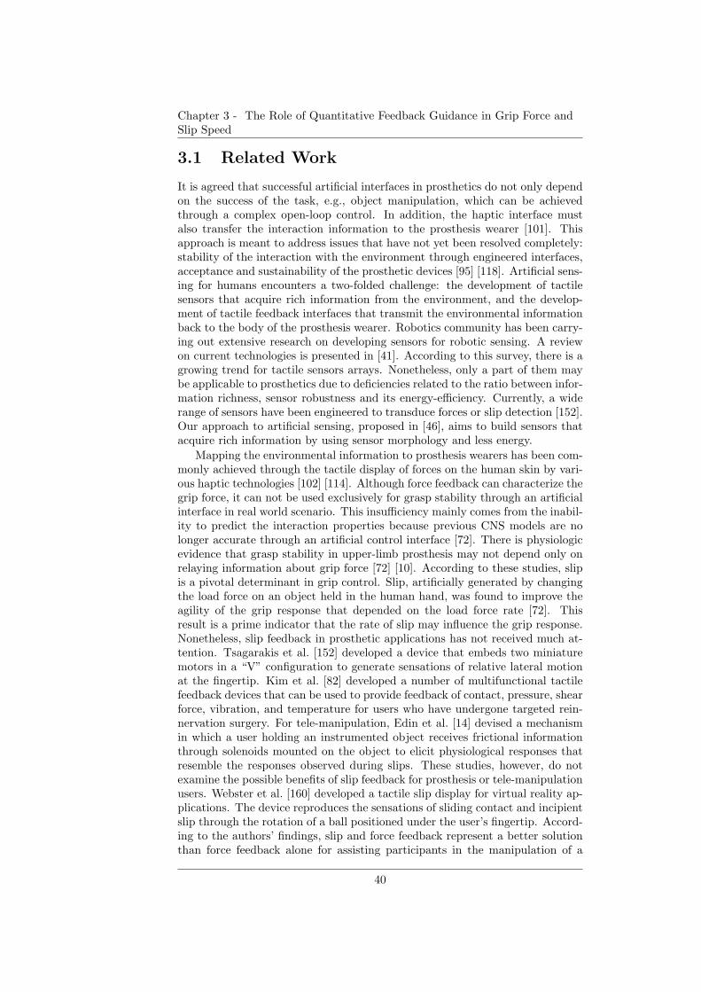
Chapter 3 - The Role of Quantitative Feedback Guidance in Grip Force andSlip Speed
3.1 Related Work
It is agreed that successful artificial interfaces in prosthetics do not only dependon the success of the task, e.g., object manipulation, which can be achievedthrough a complex open-loop control. In addition, the haptic interface mustalso transfer the interaction information to the prosthesis wearer [101]. Thisapproach is meant to address issues that have not yet been resolved completely:stability of the interaction with the environment through engineered interfaces,acceptance and sustainability of the prosthetic devices [95] [118]. Artificial sens-ing for humans encounters a two-folded challenge: the development of tactilesensors that acquire rich information from the environment, and the develop-ment of tactile feedback interfaces that transmit the environmental informationback to the body of the prosthesis wearer. Robotics community has been carry-ing out extensive research on developing sensors for robotic sensing. A reviewon current technologies is presented in [41]. According to this survey, there is agrowing trend for tactile sensors arrays. Nonetheless, only a part of them maybe applicable to prosthetics due to deficiencies related to the ratio between infor-mation richness, sensor robustness and its energy-efficiency. Currently, a widerange of sensors have been engineered to transduce forces or slip detection [152].Our approach to artificial sensing, proposed in [46], aims to build sensors thatacquire rich information by using sensor morphology and less energy.
Mapping the environmental information to prosthesis wearers has been com-monly achieved through the tactile display of forces on the human skin by vari-ous haptic technologies [102] [114]. Although force feedback can characterize thegrip force, it can not be used exclusively for grasp stability through an artificialinterface in real world scenario. This insufficiency mainly comes from the inabil-ity to predict the interaction properties because previous CNS models are nolonger accurate through an artificial control interface [72]. There is physiologicevidence that grasp stability in upper-limb prosthesis may not depend only onrelaying information about grip force [72] [10]. According to these studies, slipis a pivotal determinant in grip control. Slip, artificially generated by changingthe load force on an object held in the human hand, was found to improve theagility of the grip response that depended on the load force rate [72]. Thisresult is a prime indicator that the rate of slip may influence the grip response.Nonetheless, slip feedback in prosthetic applications has not received much at-tention. Tsagarakis et al. [152] developed a device that embeds two miniaturemotors in a “V” configuration to generate sensations of relative lateral motionat the fingertip. Kim et al. [82] developed a number of multifunctional tactilefeedback devices that can be used to provide feedback of contact, pressure, shearforce, vibration, and temperature for users who have undergone targeted rein-nervation surgery. For tele-manipulation, Edin et al. [14] devised a mechanismin which a user holding an instrumented object receives frictional informationthrough solenoids mounted on the object to elicit physiological responses thatresemble the responses observed during slips. These studies, however, do notexamine the possible benefits of slip feedback for prosthesis or tele-manipulationusers. Webster et al. [160] developed a tactile slip display for virtual reality ap-plications. The device reproduces the sensations of sliding contact and incipientslip through the rotation of a ball positioned under the user’s fingertip. Accord-ing to the authors’ findings, slip and force feedback represent a better solutionthan force feedback alone for assisting participants in the manipulation of a
40
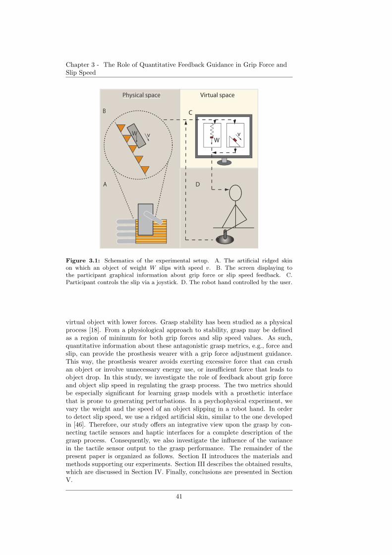
Chapter 3 - The Role of Quantitative Feedback Guidance in Grip Force andSlip Speed
vWW
v
C
D
B
A
Physical space Virtual space
D
vWW
B
A
Physical space
Figure 3.1: Schematics of the experimental setup. A. The artificial ridged skinon which an object of weight W slips with speed v. B. The screen displaying tothe participant graphical information about grip force or slip speed feedback. C.Participant controls the slip via a joystick. D. The robot hand controlled by the user.
virtual object with lower forces. Grasp stability has been studied as a physicalprocess [18]. From a physiological approach to stability, grasp may be definedas a region of minimum for both grip forces and slip speed values. As such,quantitative information about these antagonistic grasp metrics, e.g., force andslip, can provide the prosthesis wearer with a grip force adjustment guidance.This way, the prosthesis wearer avoids exerting excessive force that can crushan object or involve unnecessary energy use, or insufficient force that leads toobject drop. In this study, we investigate the role of feedback about grip forceand object slip speed in regulating the grasp process. The two metrics shouldbe especially significant for learning grasp models with a prosthetic interfacethat is prone to generating perturbations. In a psychophysical experiment, wevary the weight and the speed of an object slipping in a robot hand. In orderto detect slip speed, we use a ridged artificial skin, similar to the one developedin [46]. Therefore, our study offers an integrative view upon the grasp by con-necting tactile sensors and haptic interfaces for a complete description of thegrasp process. Consequently, we also investigate the influence of the variancein the tactile sensor output to the grasp performance. The remainder of thepresent paper is organized as follows. Section II introduces the materials andmethods supporting our experiments. Section III describes the obtained results,which are discussed in Section IV. Finally, conclusions are presented in SectionV.
41
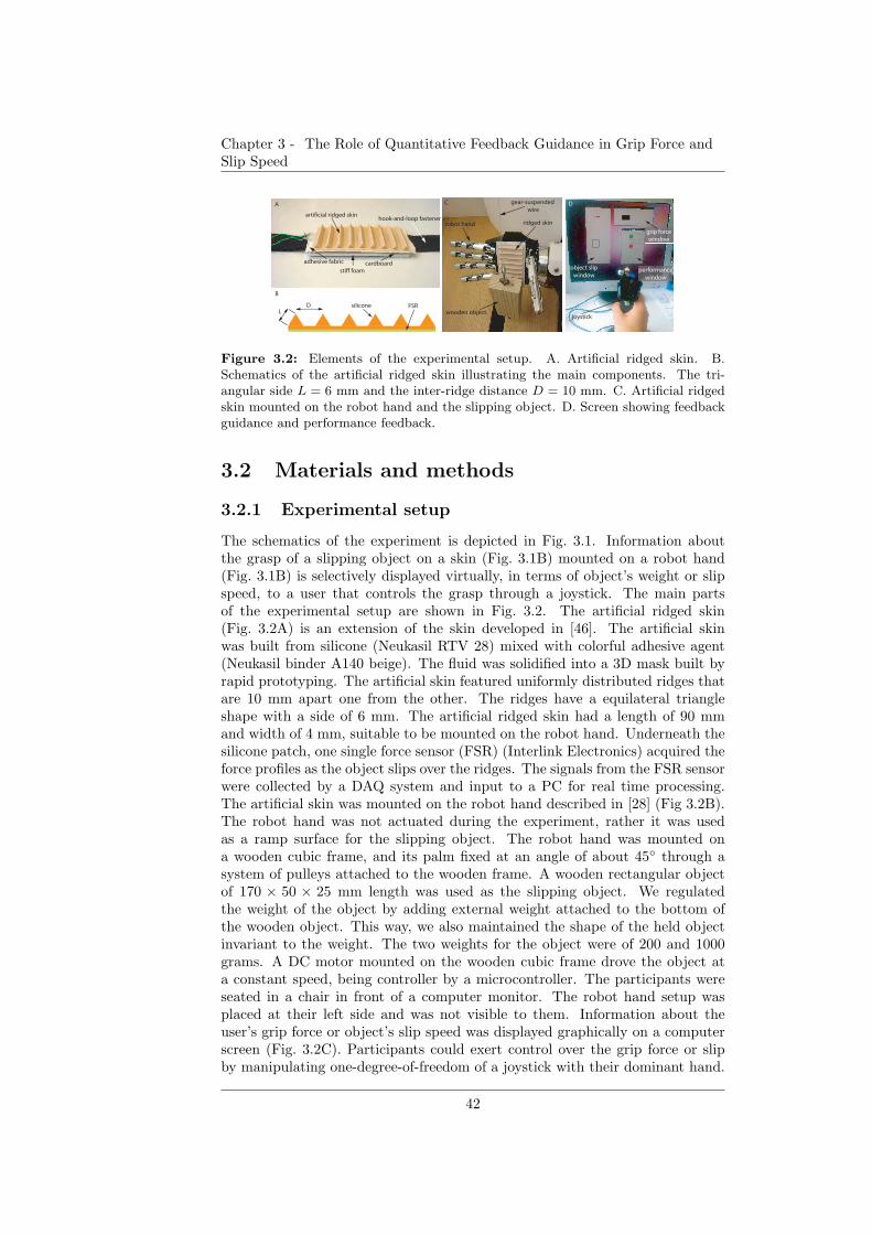
Chapter 3 - The Role of Quantitative Feedback Guidance in Grip Force andSlip Speed
hook-and-loop fastenerartificial ridged skin
stiff foamcardboardadhesive fabric
A C
robot hand ridged skin
wooden object
object slip
window
joystick
performance
window
grip force
window
D
B
DL
silicone FSR
gear-suspended
wire
Figure 3.2: Elements of the experimental setup. A. Artificial ridged skin. B.Schematics of the artificial ridged skin illustrating the main components. The tri-angular side L = 6 mm and the inter-ridge distance D = 10 mm. C. Artificial ridgedskin mounted on the robot hand and the slipping object. D. Screen showing feedbackguidance and performance feedback.
3.2 Materials and methods
3.2.1 Experimental setup
The schematics of the experiment is depicted in Fig. 3.1. Information aboutthe grasp of a slipping object on a skin (Fig. 3.1B) mounted on a robot hand(Fig. 3.1B) is selectively displayed virtually, in terms of object’s weight or slipspeed, to a user that controls the grasp through a joystick. The main partsof the experimental setup are shown in Fig. 3.2. The artificial ridged skin(Fig. 3.2A) is an extension of the skin developed in [46]. The artificial skinwas built from silicone (Neukasil RTV 28) mixed with colorful adhesive agent(Neukasil binder A140 beige). The fluid was solidified into a 3D mask built byrapid prototyping. The artificial skin featured uniformly distributed ridges thatare 10 mm apart one from the other. The ridges have a equilateral triangleshape with a side of 6 mm. The artificial ridged skin had a length of 90 mmand width of 4 mm, suitable to be mounted on the robot hand. Underneath thesilicone patch, one single force sensor (FSR) (Interlink Electronics) acquired theforce profiles as the object slips over the ridges. The signals from the FSR sensorwere collected by a DAQ system and input to a PC for real time processing.The artificial skin was mounted on the robot hand described in [28] (Fig 3.2B).The robot hand was not actuated during the experiment, rather it was usedas a ramp surface for the slipping object. The robot hand was mounted ona wooden cubic frame, and its palm fixed at an angle of about 45◦ through asystem of pulleys attached to the wooden frame. A wooden rectangular objectof 170 × 50 × 25 mm length was used as the slipping object. We regulatedthe weight of the object by adding external weight attached to the bottom ofthe wooden object. This way, we also maintained the shape of the held objectinvariant to the weight. The two weights for the object were of 200 and 1000grams. A DC motor mounted on the wooden cubic frame drove the object ata constant speed, being controller by a microcontroller. The participants wereseated in a chair in front of a computer monitor. The robot hand setup wasplaced at their left side and was not visible to them. Information about theuser’s grip force or object’s slip speed was displayed graphically on a computerscreen (Fig. 3.2C). Participants could exert control over the grip force or slipby manipulating one-degree-of-freedom of a joystick with their dominant hand.
42
Chapter 3 - The Role of Quantitative Feedback Guidance in Grip Force andSlip Speed
They were also deprived of environmental noise by wearing headphones duringthe experiment.
3.2.2 Experimental procedure
Seven unimpaired volunteers ranging in age from 23 to 35 years participatedin three experiments, after having read the instructions and having given theirconsent. Prior to commencing the study, ethical clearance was provided by theSwiss Association of Ethics Committees (KEK). The task of the participant isto stop a slipping object with an optimal grip force. Within an experimentalsession, an object slipped over the artificial ridged skin at a constant speed. Weused three values for the real speed of the object: 10, 30 and 50 mm/s. The slipspeed of the object was generated randomly at the beginning of each session.The participants are relayed with feedback information about the interaction be-tween the robot hand and the object (virtual grip force or physical slip speed orboth). Participants could control slip by pulling the handle of the joystick fromthe neutral position toward the user in order to increase the grip force virtually.By pressing a button on the joystick, they confirmed the value of the grip forcethat they decided to be suitable to efficiently stop slip. This mapping would inreality control a robotic hand closure that tightens the grip. Twenty-four suchsessions represent one experiment. We conducted a total of three experiments inwhich in which participants were relayed with three distinct feedbacks. Prior toall experiments, we defined the efficient grip force for each weight of the slippingobject relative to the physical setup. We determined the value of the joystickdisplacement that corresponds to the slip margin, Tg. The object started to slipfor joystick displacements below this threshold. The efficient grip force was thusset as the interval between the experimental threshold, Tg, and an addition of50 joystick displacements units, Tg + 50.
The graphical interface included selected feedback information about user’sgrip force or object’s slip speed during a session and information about user’sperformance at the end of each session (Fig. 3.2C):
Grip force feedback
The grip force was graphically displayed by the horizontal expansion or con-traction of a filled rectangle. The displacement of the joystick was propor-tionally mapped to the length of the graphical rectangle, normalized based ona priori information about the range of joystick displacement and the rangeof robot fingers flexion around the experimental object. The relation, Fg =(Jx ∗ 800)/32767 [JU ] expresses the grip force in terms of joystick displacementunits, JU.
Slip speed feedback
The slip speed information, extracted from the frequency in the force signalof the artificial ridged skin, was linearly mapped to the speed of a rectanglemoving vertically on the screen. We automatically collect the force signal fromthe artificial skin as the object slips over the first five ridges of the skin, that is,along 50 mm of skin. We applied the FFT to this force signals. The extractedpeak frequency of the signal was used to compute the slip speed of the object
43
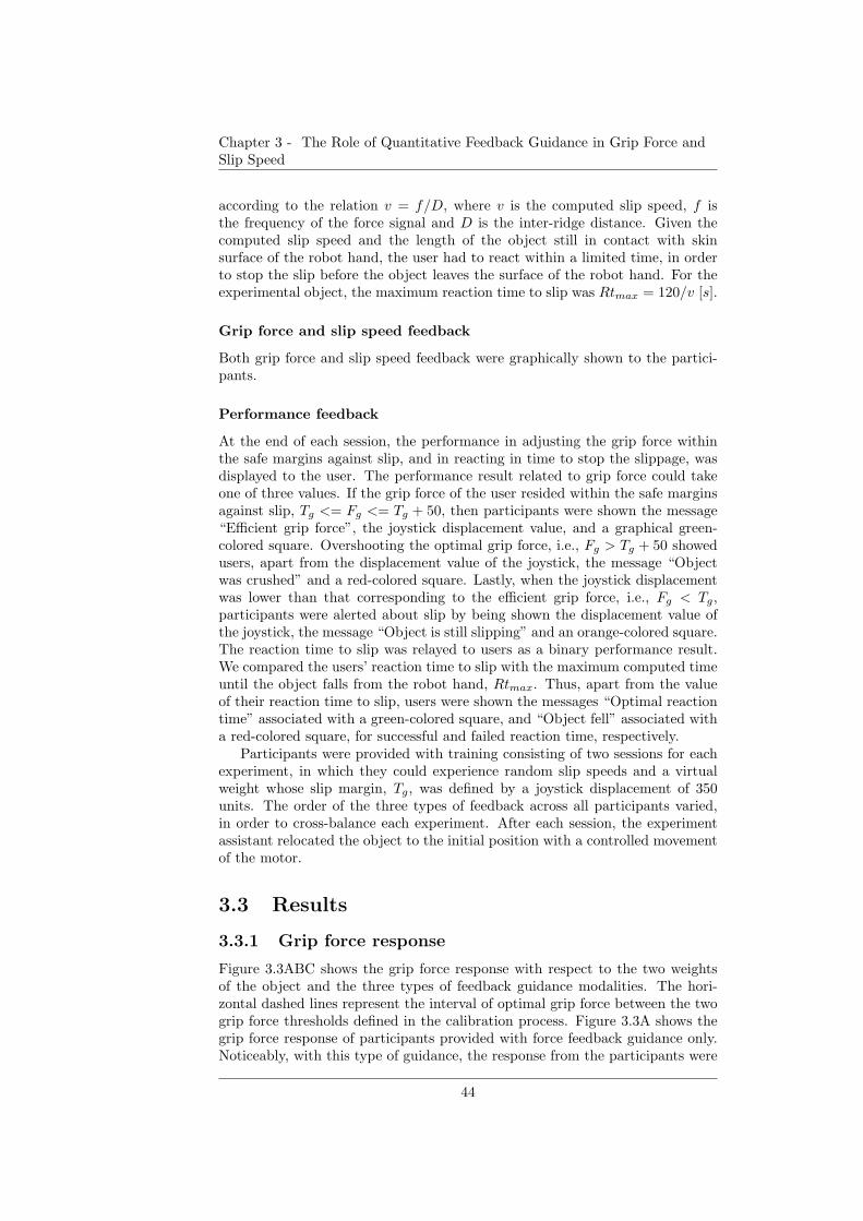
Chapter 3 - The Role of Quantitative Feedback Guidance in Grip Force andSlip Speed
according to the relation v = f/D, where v is the computed slip speed, f isthe frequency of the force signal and D is the inter-ridge distance. Given thecomputed slip speed and the length of the object still in contact with skinsurface of the robot hand, the user had to react within a limited time, in orderto stop the slip before the object leaves the surface of the robot hand. For theexperimental object, the maximum reaction time to slip was Rtmax = 120/v [s].
Grip force and slip speed feedback
Both grip force and slip speed feedback were graphically shown to the partici-pants.
Performance feedback
At the end of each session, the performance in adjusting the grip force withinthe safe margins against slip, and in reacting in time to stop the slippage, wasdisplayed to the user. The performance result related to grip force could takeone of three values. If the grip force of the user resided within the safe marginsagainst slip, Tg <= Fg <= Tg + 50, then participants were shown the message“Efficient grip force”, the joystick displacement value, and a graphical green-colored square. Overshooting the optimal grip force, i.e., Fg > Tg + 50 showedusers, apart from the displacement value of the joystick, the message “Objectwas crushed” and a red-colored square. Lastly, when the joystick displacementwas lower than that corresponding to the efficient grip force, i.e., Fg < Tg,participants were alerted about slip by being shown the displacement value ofthe joystick, the message “Object is still slipping” and an orange-colored square.The reaction time to slip was relayed to users as a binary performance result.We compared the users’ reaction time to slip with the maximum computed timeuntil the object falls from the robot hand, Rtmax. Thus, apart from the valueof their reaction time to slip, users were shown the messages “Optimal reactiontime” associated with a green-colored square, and “Object fell” associated witha red-colored square, for successful and failed reaction time, respectively.
Participants were provided with training consisting of two sessions for eachexperiment, in which they could experience random slip speeds and a virtualweight whose slip margin, Tg, was defined by a joystick displacement of 350units. The order of the three types of feedback across all participants varied,in order to cross-balance each experiment. After each session, the experimentassistant relocated the object to the initial position with a controlled movementof the motor.
3.3 Results
3.3.1 Grip force response
Figure 3.3ABC shows the grip force response with respect to the two weightsof the object and the three types of feedback guidance modalities. The hori-zontal dashed lines represent the interval of optimal grip force between the twogrip force thresholds defined in the calibration process. Figure 3.3A shows thegrip force response of participants provided with force feedback guidance only.Noticeably, with this type of guidance, the response from the participants were
44

Chapter 3 - The Role of Quantitative Feedback Guidance in Grip Force andSlip Speed
A
B
C
570 640
0
100
200
300
400
500
600
700
800
Gri
p f
orc
e
[Jo
ysti
ck d
isp
lace
me
nt]
Weight [Joystick displacement]
570 640
0
200
400
600
800
570 640
570 640
0
100
200
300
400
500
600
700
800
Gri
p f
orc
e [J
oys
tick
dis
pla
cem
en
t]
Weight [ Joystick displacement]
Gri
p f
orc
e [J
oys
tick
dis
pla
cem
en
t]
Weight [ Joystick displacement]
A
B
C
Slip margin
Slip margin
Slip margin
Figure 3.3: Grasp force with respect to object weight with force feedback guidancealone (A), slip speed feedback guidance alone(B), force and slip speed feedback guid-ance combined (C). Slip margin designates the grip force level under which the objectstarts to slip. This level was determined empirically with the robot hand platform.
45
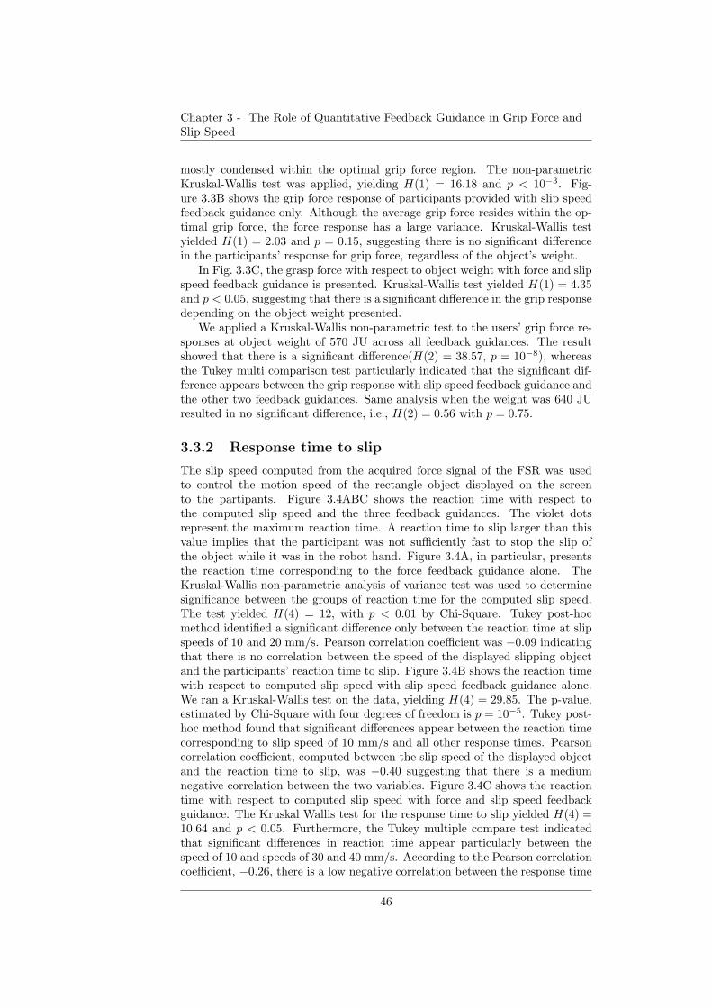
Chapter 3 - The Role of Quantitative Feedback Guidance in Grip Force andSlip Speed
mostly condensed within the optimal grip force region. The non-parametricKruskal-Wallis test was applied, yielding H(1) = 16.18 and p < 10−3. Fig-ure 3.3B shows the grip force response of participants provided with slip speedfeedback guidance only. Although the average grip force resides within the op-timal grip force, the force response has a large variance. Kruskal-Wallis testyielded H(1) = 2.03 and p = 0.15, suggesting there is no significant differencein the participants’ response for grip force, regardless of the object’s weight.
In Fig. 3.3C, the grasp force with respect to object weight with force and slipspeed feedback guidance is presented. Kruskal-Wallis test yielded H(1) = 4.35and p < 0.05, suggesting that there is a significant difference in the grip responsedepending on the object weight presented.
We applied a Kruskal-Wallis non-parametric test to the users’ grip force re-sponses at object weight of 570 JU across all feedback guidances. The resultshowed that there is a significant difference(H(2) = 38.57, p = 10−8), whereasthe Tukey multi comparison test particularly indicated that the significant dif-ference appears between the grip response with slip speed feedback guidance andthe other two feedback guidances. Same analysis when the weight was 640 JUresulted in no significant difference, i.e., H(2) = 0.56 with p = 0.75.
3.3.2 Response time to slip
The slip speed computed from the acquired force signal of the FSR was usedto control the motion speed of the rectangle object displayed on the screento the partipants. Figure 3.4ABC shows the reaction time with respect tothe computed slip speed and the three feedback guidances. The violet dotsrepresent the maximum reaction time. A reaction time to slip larger than thisvalue implies that the participant was not sufficiently fast to stop the slip ofthe object while it was in the robot hand. Figure 3.4A, in particular, presentsthe reaction time corresponding to the force feedback guidance alone. TheKruskal-Wallis non-parametric analysis of variance test was used to determinesignificance between the groups of reaction time for the computed slip speed.The test yielded H(4) = 12, with p < 0.01 by Chi-Square. Tukey post-hocmethod identified a significant difference only between the reaction time at slipspeeds of 10 and 20 mm/s. Pearson correlation coefficient was −0.09 indicatingthat there is no correlation between the speed of the displayed slipping objectand the participants’ reaction time to slip. Figure 3.4B shows the reaction timewith respect to computed slip speed with slip speed feedback guidance alone.We ran a Kruskal-Wallis test on the data, yielding H(4) = 29.85. The p-value,estimated by Chi-Square with four degrees of freedom is p = 10−5. Tukey post-hoc method found that significant differences appear between the reaction timecorresponding to slip speed of 10 mm/s and all other response times. Pearsoncorrelation coefficient, computed between the slip speed of the displayed objectand the reaction time to slip, was −0.40 suggesting that there is a mediumnegative correlation between the two variables. Figure 3.4C shows the reactiontime with respect to computed slip speed with force and slip speed feedbackguidance. The Kruskal Wallis test for the response time to slip yielded H(4) =10.64 and p < 0.05. Furthermore, the Tukey multiple compare test indicatedthat significant differences in reaction time appear particularly between thespeed of 10 and speeds of 30 and 40 mm/s. According to the Pearson correlationcoefficient, −0.26, there is a low negative correlation between the response time
46
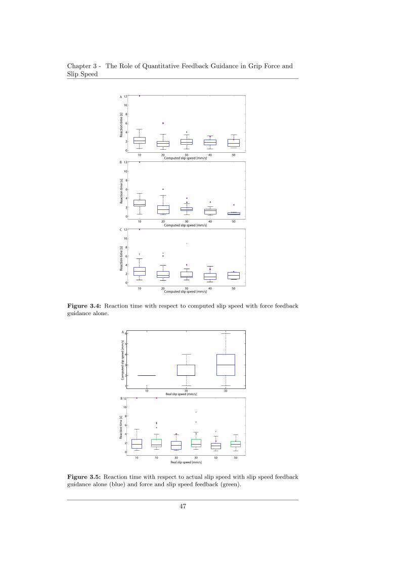
Chapter 3 - The Role of Quantitative Feedback Guidance in Grip Force andSlip Speed
10 20 30 40 50
0
2
4
6
8
10
12
Re
acti
on
tim
e [s
]
B
10 20 30 40 50
0
2
4
6
8
10
12
Re
acti
on
tim
e [s
]
Computed slip speed [mm/s]
A
10 20 30 40 50
0
2
4
6
8
10
12
Re
acti
on
tim
e [s
]
Computed slip speed [mm/s]
C
Computed slip speed [mm/s]
Figure 3.4: Reaction time with respect to computed slip speed with force feedbackguidance alone.
10 30 50
1
2
3
4
5
6
Real slip speed [mm/s]
Co
mp
ute
d s
lip s
pe
ed
[mm
/s]
10 10 30 30 50 50
0
2
4
6
8
10
12
Real slip speed [mm/s]
Re
acti
on
tim
e [s
]
A
B
Figure 3.5: Reaction time with respect to actual slip speed with slip speed feedbackguidance alone (blue) and force and slip speed feedback (green).
47
Chapter 3 - The Role of Quantitative Feedback Guidance in Grip Force andSlip Speed
to slip and the moving speed of the graphical object.
3.3.3 Effect of slip speed detection variance
We evaluated the performance of the artificial ridged skin in detecting the speedof the slipping object. The mismatches between the real and computed speedare presented in Fig. 3.5A. Statistically, there is however a significant differencebetween the values of the computed speeds. The single factor one-way ANOVAyielded F (2, 491) = 51.39 and p < 0.001. We further investigated whether thevariance in the slip speed detection significantly affects grasp stability. Fig-ure 3.5B illustrates the reaction time to slip taking into account the real slipspeed of the object. The errors, computed as a difference between the actualreaction time and the maximum reaction time (in violet bullets) for all condi-tions, showed no significant difference when Kruskal Wallis test was applied andwere all classified as outliers.
3.3.4 Grasp success
We computed the rate of success in achieving a grip force within the optimalgrasp region and a reaction time lower than the maximum response time toslip, depending on the feedback guidance, for all participants. The reactiontime has been considered as a function of the real speed, in order to obtainan estimation of success closer to the potential real grasp scenario. Figure 3.6shows the percentage of success to stop slip in time and reach an optimal graspforce. The highest success ratio for optimal grip force was obtained with forcefeedback guidance, whereas the highest success ratio for an in-time response toslip was achieved via the slip speed feedback guidance.
3.4 Discussion
The artificial ridged skin decreased its efficiency as the slip speed increases.While for slip speeds of 10 and 30 mm/s the performance was fair, slip speed of50 mm/s had the largest variance. The post-processing of the acquired signalsrequire several computations of the frequency to provide a value closer to thereal slip speed. Due to a high slip speed, there are not sufficient frequenciescomputed over the acquired samples in order to yield a more accurate slipspeed.
The analysis conducted for the grip force response clearly showed that thegrip force can be adjusted with information about the normal force applied tothe grasped object. Furthermore, the analysis performed on the grip reactiontime, showed that the most significant and variate adjustments on the reactiontime took place with slip speed guidance alone or with force and slip speedguidance combined. Slip speed feedback has been found to improve the successin finding the optimal grip force in [42], featuring agility, energy efficiency andless response variability. The current result further contributes by indicatingthat feedback about slip speed regulates the reaction time to grasp. The resultfinds physiological support in studies performed with human users holding anobject in their healthy hand [72].
48
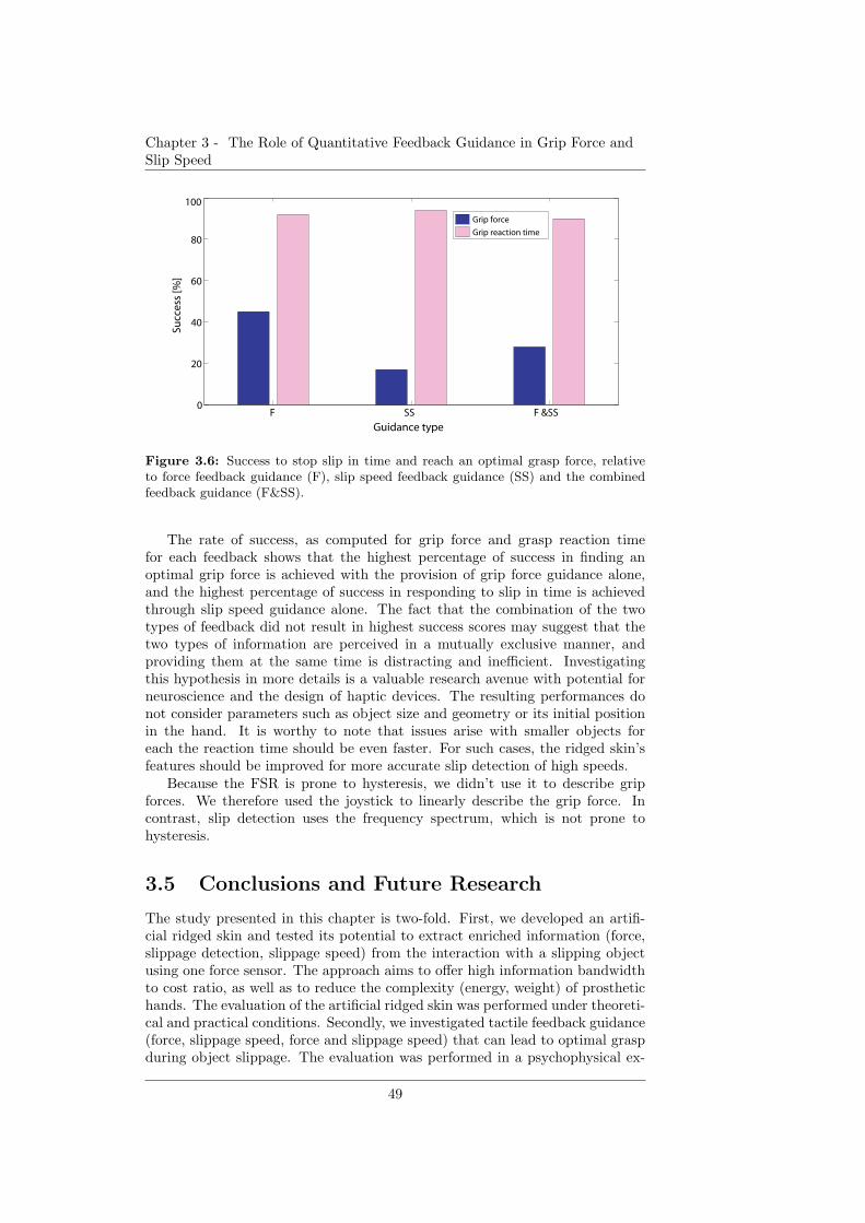
Chapter 3 - The Role of Quantitative Feedback Guidance in Grip Force andSlip Speed
F SS F &SS0
20
40
60
80
100
Guidance type
Succ
ess
[%]
Grip force
Grip reaction time
Figure 3.6: Success to stop slip in time and reach an optimal grasp force, relativeto force feedback guidance (F), slip speed feedback guidance (SS) and the combinedfeedback guidance (F&SS).
The rate of success, as computed for grip force and grasp reaction timefor each feedback shows that the highest percentage of success in finding anoptimal grip force is achieved with the provision of grip force guidance alone,and the highest percentage of success in responding to slip in time is achievedthrough slip speed guidance alone. The fact that the combination of the twotypes of feedback did not result in highest success scores may suggest that thetwo types of information are perceived in a mutually exclusive manner, andproviding them at the same time is distracting and inefficient. Investigatingthis hypothesis in more details is a valuable research avenue with potential forneuroscience and the design of haptic devices. The resulting performances donot consider parameters such as object size and geometry or its initial positionin the hand. It is worthy to note that issues arise with smaller objects foreach the reaction time should be even faster. For such cases, the ridged skin’sfeatures should be improved for more accurate slip detection of high speeds.
Because the FSR is prone to hysteresis, we didn’t use it to describe gripforces. We therefore used the joystick to linearly describe the grip force. Incontrast, slip detection uses the frequency spectrum, which is not prone tohysteresis.
3.5 Conclusions and Future Research
The study presented in this chapter is two-fold. First, we developed an artifi-cial ridged skin and tested its potential to extract enriched information (force,slippage detection, slippage speed) from the interaction with a slipping objectusing one force sensor. The approach aims to offer high information bandwidthto cost ratio, as well as to reduce the complexity (energy, weight) of prosthetichands. The evaluation of the artificial ridged skin was performed under theoreti-cal and practical conditions. Secondly, we investigated tactile feedback guidance(force, slippage speed, force and slippage speed) that can lead to optimal graspduring object slippage. The evaluation was performed in a psychophysical ex-
49
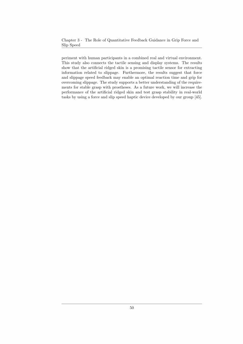
Chapter 3 - The Role of Quantitative Feedback Guidance in Grip Force andSlip Speed
periment with human participants in a combined real and virtual environment.This study also connects the tactile sensing and display systems. The resultsshow that the artificial ridged skin is a promising tactile sensor for extractinginformation related to slippage. Furthermore, the results suggest that forceand slippage speed feedback may enable an optimal reaction time and grip forovercoming slippage. The study supports a better understanding of the require-ments for stable grasp with prostheses. As a future work, we will increase theperformance of the artificial ridged skin and test grasp stability in real-worldtasks by using a force and slip speed haptic device developed by our group [45].
50

Chapter 4
Artificial Ridged Skin for
Slippage Speed Detection in
Prosthetic Hand
ApplicationsArtificial ridged skin for detectionof force, slip occurrence and speed
In this chapter, we present in detail an artificial ridged skin able to detect force,slip occurrence and speed using minimal resources.The human hand is one of the most complex structures in the body, beinginvolved in dexterous manipulation and fine sensing. Traditional engineeringapproaches have mostly attempted to match such complexity in robotics with-out sufficiently stressing on the underlying mechanisms that its morphologyencodes. In this work, we propose an artificial skin able to encode, throughits morphology, the tactile sense of a robotic hand, characteristic to slippageevents. The underlying layout consists of ridges and allows slippage detectionand the quantification of slippage speed. Such encoding of slippage signal be-comes suitable for relaying tactile feedback to users in prosthetic applications.This approach emphasizes the importance of exploiting morphology and me-chanics in structures for the design of prosthetic interfaces.
3Parts of the material in this chapter previously appeared in: D.D. Damian, H. Martinez,K. Dermitzakis, A. Hernandez Arieta and R. Pfeifer (2010) “Artificial Ridged Skin for SlippageSpeed Detection in Prosthetic Hand Applications”, IEEE/RSJ International Conference onIntelligent Robots and Systems (IROS), pp. 904 - 909.
51
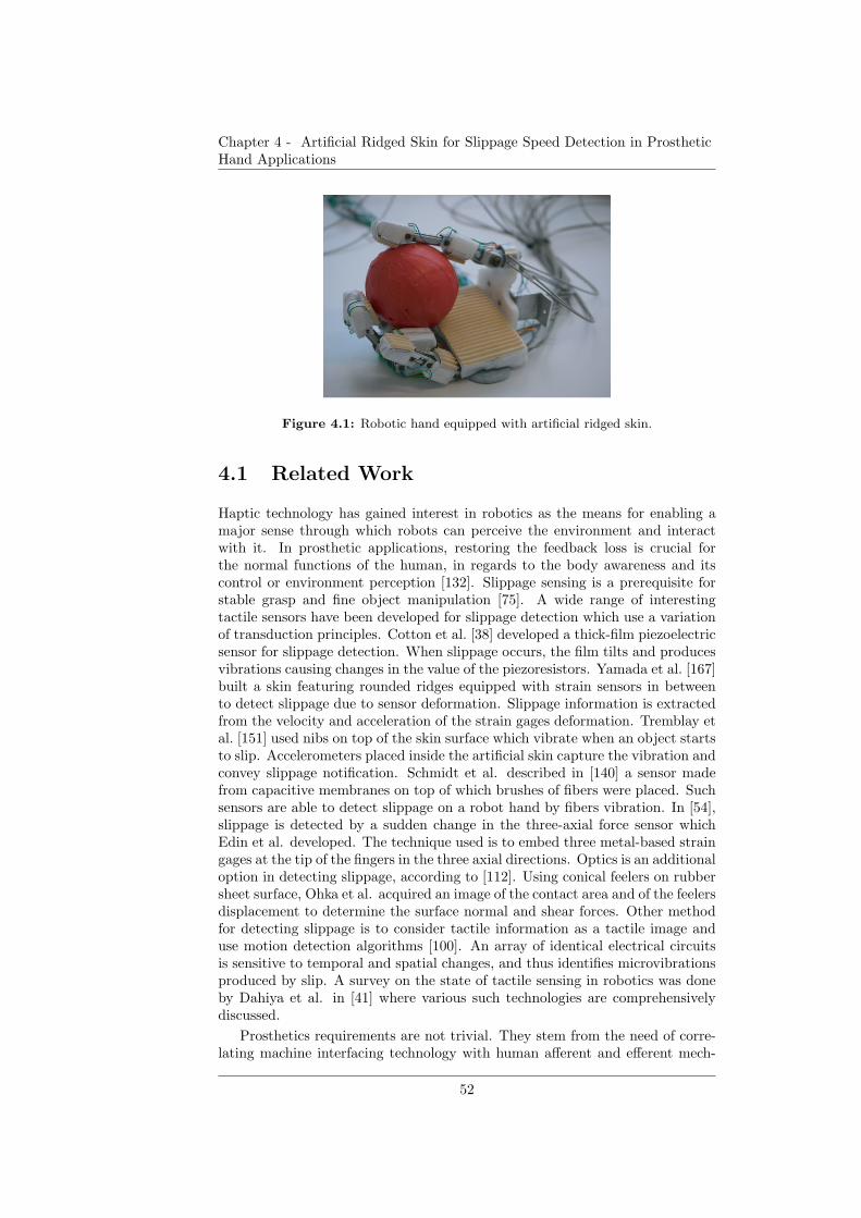
Chapter 4 - Artificial Ridged Skin for Slippage Speed Detection in ProstheticHand Applications
Figure 4.1: Robotic hand equipped with artificial ridged skin.
4.1 Related Work
Haptic technology has gained interest in robotics as the means for enabling amajor sense through which robots can perceive the environment and interactwith it. In prosthetic applications, restoring the feedback loss is crucial forthe normal functions of the human, in regards to the body awareness and itscontrol or environment perception [132]. Slippage sensing is a prerequisite forstable grasp and fine object manipulation [75]. A wide range of interestingtactile sensors have been developed for slippage detection which use a variationof transduction principles. Cotton et al. [38] developed a thick-film piezoelectricsensor for slippage detection. When slippage occurs, the film tilts and producesvibrations causing changes in the value of the piezoresistors. Yamada et al. [167]built a skin featuring rounded ridges equipped with strain sensors in betweento detect slippage due to sensor deformation. Slippage information is extractedfrom the velocity and acceleration of the strain gages deformation. Tremblay etal. [151] used nibs on top of the skin surface which vibrate when an object startsto slip. Accelerometers placed inside the artificial skin capture the vibration andconvey slippage notification. Schmidt et al. described in [140] a sensor madefrom capacitive membranes on top of which brushes of fibers were placed. Suchsensors are able to detect slippage on a robot hand by fibers vibration. In [54],slippage is detected by a sudden change in the three-axial force sensor whichEdin et al. developed. The technique used is to embed three metal-based straingages at the tip of the fingers in the three axial directions. Optics is an additionaloption in detecting slippage, according to [112]. Using conical feelers on rubbersheet surface, Ohka et al. acquired an image of the contact area and of the feelersdisplacement to determine the surface normal and shear forces. Other methodfor detecting slippage is to consider tactile information as a tactile image anduse motion detection algorithms [100]. An array of identical electrical circuitsis sensitive to temporal and spatial changes, and thus identifies microvibrationsproduced by slip. A survey on the state of tactile sensing in robotics was doneby Dahiya et al. in [41] where various such technologies are comprehensivelydiscussed.
Prosthetics requirements are not trivial. They stem from the need of corre-lating machine interfacing technology with human afferent and efferent mech-
52
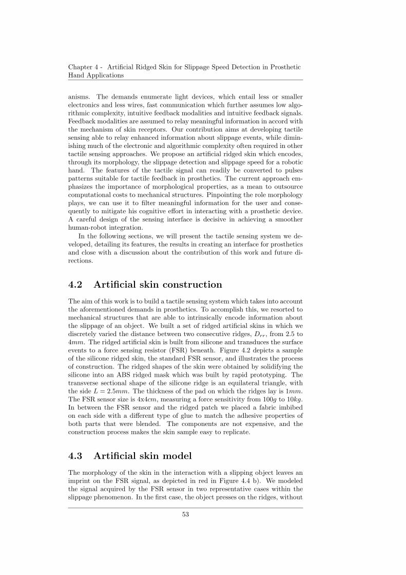
Chapter 4 - Artificial Ridged Skin for Slippage Speed Detection in ProstheticHand Applications
anisms. The demands enumerate light devices, which entail less or smallerelectronics and less wires, fast communication which further assumes low algo-rithmic complexity, intuitive feedback modalities and intuitive feedback signals.Feedback modalities are assumed to relay meaningful information in accord withthe mechanism of skin receptors. Our contribution aims at developing tactilesensing able to relay enhanced information about slippage events, while dimin-ishing much of the electronic and algorithmic complexity often required in othertactile sensing approaches. We propose an artificial ridged skin which encodes,through its morphology, the slippage detection and slippage speed for a robotichand. The features of the tactile signal can readily be converted to pulsespatterns suitable for tactile feedback in prosthetics. The current approach em-phasizes the importance of morphological properties, as a mean to outsourcecomputational costs to mechanical structures. Pinpointing the role morphologyplays, we can use it to filter meaningful information for the user and conse-quently to mitigate his cognitive effort in interacting with a prosthetic device.A careful design of the sensing interface is decisive in achieving a smootherhuman-robot integration.
In the following sections, we will present the tactile sensing system we de-veloped, detailing its features, the results in creating an interface for prostheticsand close with a discussion about the contribution of this work and future di-rections.
4.2 Artificial skin construction
The aim of this work is to build a tactile sensing system which takes into accountthe aforementioned demands in prosthetics. To accomplish this, we resorted tomechanical structures that are able to intrinsically encode information aboutthe slippage of an object. We built a set of ridged artificial skins in which wediscretely varied the distance between two consecutive ridges, Drr, from 2.5 to4mm. The ridged artificial skin is built from silicone and transduces the surfaceevents to a force sensing resistor (FSR) beneath. Figure 4.2 depicts a sampleof the silicone ridged skin, the standard FSR sensor, and illustrates the processof construction. The ridged shapes of the skin were obtained by solidifying thesilicone into an ABS ridged mask which was built by rapid prototyping. Thetransverse sectional shape of the silicone ridge is an equilateral triangle, withthe side L = 2.5mm. The thickness of the pad on which the ridges lay is 1mm.The FSR sensor size is 4x4cm, measuring a force sensitivity from 100g to 10kg.In between the FSR sensor and the ridged patch we placed a fabric imbibedon each side with a different type of glue to match the adhesive properties ofboth parts that were blended. The components are not expensive, and theconstruction process makes the skin sample easy to replicate.
4.3 Artificial skin model
The morphology of the skin in the interaction with a slipping object leaves animprint on the FSR signal, as depicted in red in Figure 4.4 b). We modeledthe signal acquired by the FSR sensor in two representative cases within theslippage phenomenon. In the first case, the object presses on the ridges, without
53
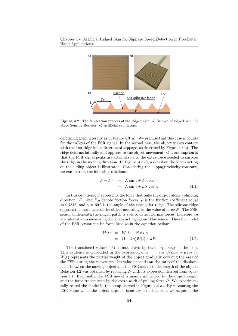
Chapter 4 - Artificial Ridged Skin for Slippage Speed Detection in ProstheticHand Applications
DrrL
Silicone
Self-adhesive fabricFSR
a) b)
c)
Figure 4.2: The fabrication process of the ridged skin. a) Sample of ridged skin. b)Force Sensing Resistor. c) Artificial skin layers.
deforming them laterally as in Figure 4.3 a). We premise that this case accountsfor the valleys of the FSR signal. In the second case, the object makes contactwith the first ridge in its direction of slippage, as described by Figure 4.3 b). Theridge deforms laterally and opposes to the object movement. Our assumption isthat the FSR signal peaks are attributable to the extra-force needed to surpassthe ridge in the moving direction. In Figure 4.3 c), a detail on the forces actingon the sliding object is illustrated. Considering the slippage velocity constant,we can extract the following relations:
P − Fr1 = N sin γ + Fr2 cos γ
= N sin γ + µN cos γ. (4.1)
In this equations, P represents the force that pulls the object along a slippingdirection. Fr1 and Fr2 denote friction forces, µ is the friction coefficient equalto 0.7813, and γ = 60 ◦ is the angle of the triangular ridge. The silicone ridgeopposes the movement of the object according to the value of force N . The FSRsensor underneath the ridged patch is able to detect normal forces, therefore weare interested in measuring the forces acting against this sensor. Thus the modelof the FSR sensor can be formalized as in the equation bellow:
M(t) = W (t) +N cos γ
= (1− kµ)W (t) + kP. (4.2)
The transduced value of M is modulated by the morphology of the skin.This evidence is embedded in the expression of k = cos γ/(sin γ + µ cos γ).W (t) represents the partial weight of the object gradually covering the area ofthe FSR during the movement. Its value depends on the ratio of the displace-ment between the moving object and the FSR sensor to the length of the object.Relation 4.2 was obtained by replacing N with its expression derived from equa-tion 4.1. Eventually, the FSR model is mainly influenced by the object weightand the force transmitted by the extra-work of pulling force P . We experimen-tally tested the model in the setup showed in Figure 4.4 a). By measuring theFSR value when the object slips horizontally on a flat skin, we acquired the
54
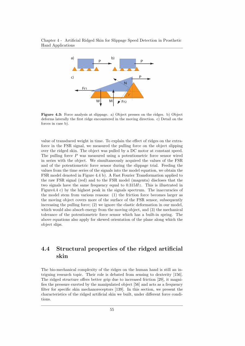
Chapter 4 - Artificial Ridged Skin for Slippage Speed Detection in ProstheticHand Applications
PPa) b)
P
Fr1
Fr2W M
N
c)
Figure 4.3: Force analysis at slippage. a) Object presses on the ridges. b) Objectdeforms laterally the first ridge encountered in the moving direction. c) Detail on theforces in case b).
value of transduced weight in time. To explain the effect of ridges on the extra-force in the FSR signal, we measured the pulling force on the object slippingover the ridged skin. The object was pulled by a DC motor at constant speed.The pulling force P was measured using a potentiometric force sensor wiredin series with the object. We simultaneously acquired the values of the FSRand of the potentiometric force sensor during the slippage trial. Feeding thevalues from the time series of the signals into the model equation, we obtain theFSR model denoted in Figure 4.4 b). A Fast Fourier Transformation applied tothe raw FSR signal (red) and to the FSR model (magenta) discloses that thetwo signals have the same frequency equal to 0.315Hz. This is illustrated inFigure4.4 c) by the highest peak in the signals spectrum. The inaccuracies ofthe model stem from various reasons: (1) the friction force becomes larger asthe moving object covers more of the surface of the FSR sensor, subsequentlyincreasing the pulling force; (2) we ignore the elastic deformation in our model,which would also absorb energy from the moving object, and (3) the mechanicaltolerance of the potentiometric force sensor which has a built-in spring. Theabove equations also apply for skewed orientation of the plane along which theobject slips.
4.4 Structural properties of the ridged artificial
skin
The bio-mechanical complexity of the ridges on the human hand is still an in-triguing research topic. Their role is debated from sensing to dexterity [156].The ridged structure offers better grip due to increased friction [29], it magni-fies the pressure exerted by the manipulated object [56] and acts as a frequencyfilter for specific skin mechanoreceptors [139]. In this section, we present thecharacteristics of the ridged artificial skin we built, under different force condi-tions.
55
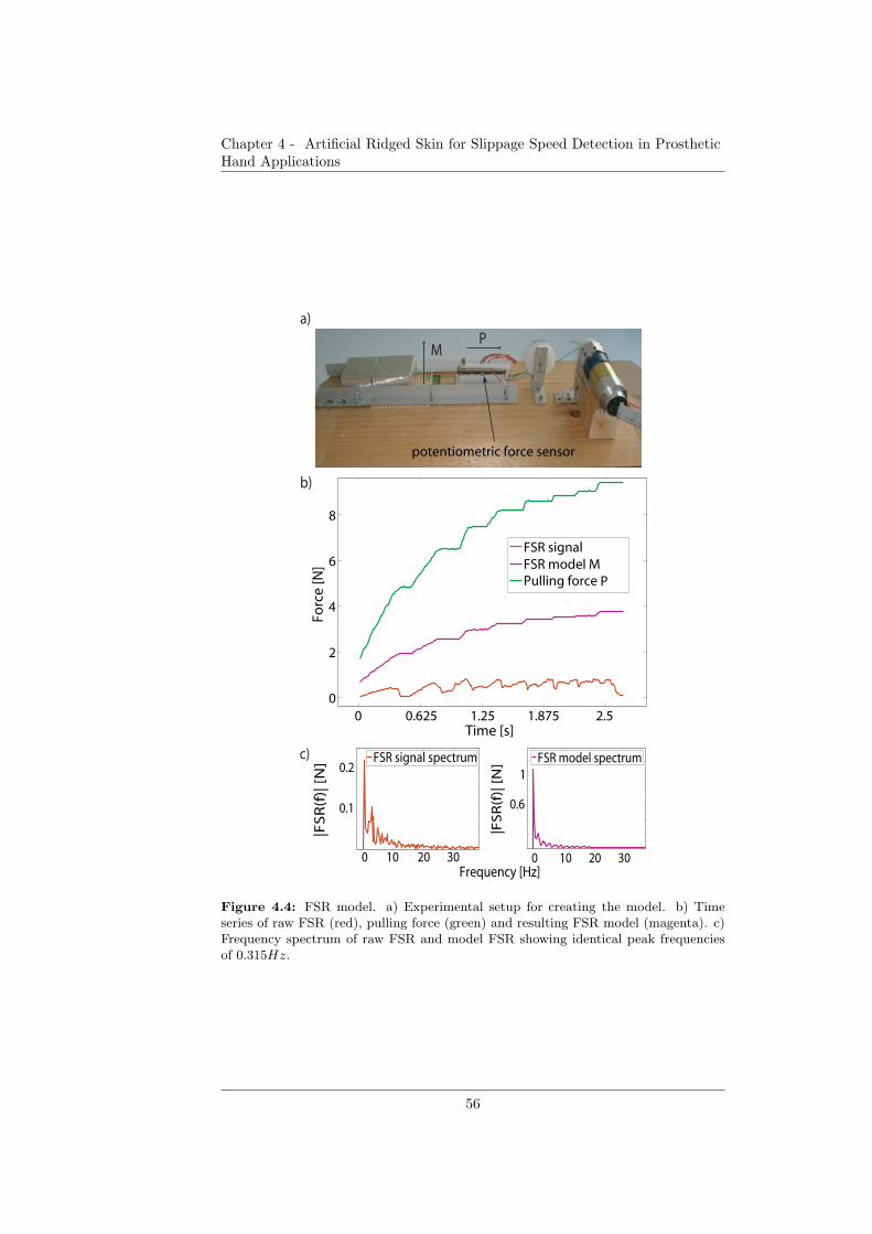
Chapter 4 - Artificial Ridged Skin for Slippage Speed Detection in ProstheticHand Applications
0 0.625 1.25 1.875 2.50
2
4
6
8
Time [s]
Forc
e [N
]
FSR signal FSR model MPulling force P
0 10 20 30
0.1
0.2
|FS
R(f
)| [
N]
0 10 20 30
0.6
1
|FS
R(f
)| [
N]
FSR model spectrumFSR signal spectrum
Frequency [Hz]
b)
c)
a)
potentiometric force sensor
PM
Figure 4.4: FSR model. a) Experimental setup for creating the model. b) Timeseries of raw FSR (red), pulling force (green) and resulting FSR model (magenta). c)Frequency spectrum of raw FSR and model FSR showing identical peak frequenciesof 0.315Hz.
56
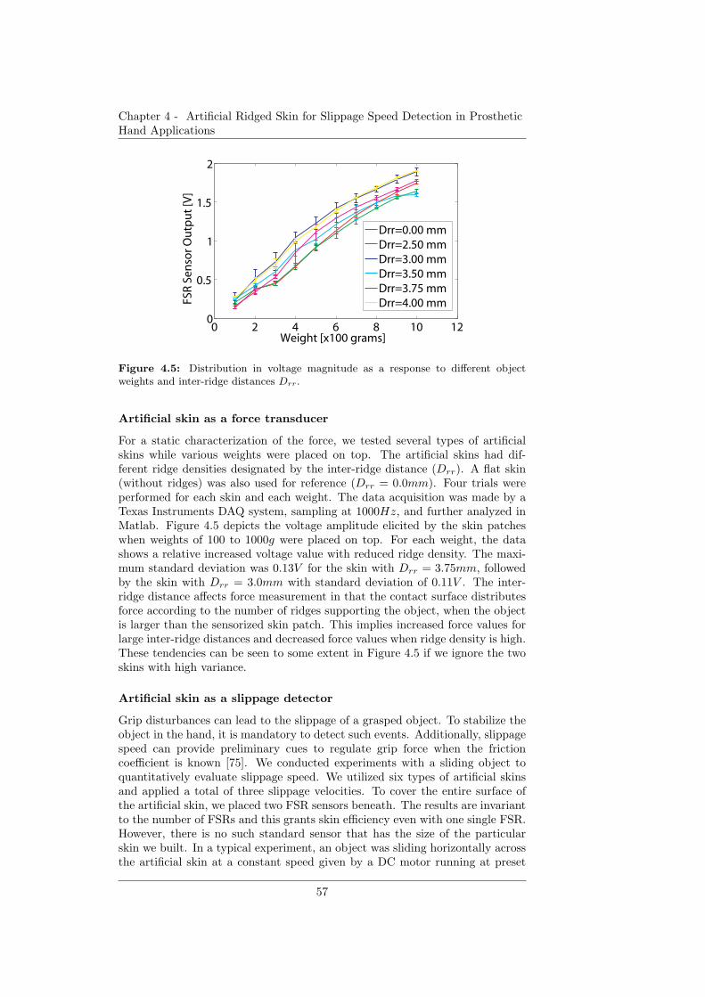
Chapter 4 - Artificial Ridged Skin for Slippage Speed Detection in ProstheticHand Applications
0 2 4 6 8 10 120
0.5
1
1.5
2
Weight [x100 grams]
FSR
Se
nso
r O
utp
ut
[V]
Drr=0.00 mmDrr=2.50 mmDrr=3.00 mmDrr=3.50 mmDrr=3.75 mmDrr=4.00 mm
Figure 4.5: Distribution in voltage magnitude as a response to different objectweights and inter-ridge distances Drr.
Artificial skin as a force transducer
For a static characterization of the force, we tested several types of artificialskins while various weights were placed on top. The artificial skins had dif-ferent ridge densities designated by the inter-ridge distance (Drr). A flat skin(without ridges) was also used for reference (Drr = 0.0mm). Four trials wereperformed for each skin and each weight. The data acquisition was made by aTexas Instruments DAQ system, sampling at 1000Hz, and further analyzed inMatlab. Figure 4.5 depicts the voltage amplitude elicited by the skin patcheswhen weights of 100 to 1000g were placed on top. For each weight, the datashows a relative increased voltage value with reduced ridge density. The maxi-mum standard deviation was 0.13V for the skin with Drr = 3.75mm, followedby the skin with Drr = 3.0mm with standard deviation of 0.11V . The inter-ridge distance affects force measurement in that the contact surface distributesforce according to the number of ridges supporting the object, when the objectis larger than the sensorized skin patch. This implies increased force values forlarge inter-ridge distances and decreased force values when ridge density is high.These tendencies can be seen to some extent in Figure 4.5 if we ignore the twoskins with high variance.
Artificial skin as a slippage detector
Grip disturbances can lead to the slippage of a grasped object. To stabilize theobject in the hand, it is mandatory to detect such events. Additionally, slippagespeed can provide preliminary cues to regulate grip force when the frictioncoefficient is known [75]. We conducted experiments with a sliding object toquantitatively evaluate slippage speed. We utilized six types of artificial skinsand applied a total of three slippage velocities. To cover the entire surface ofthe artificial skin, we placed two FSR sensors beneath. The results are invariantto the number of FSRs and this grants skin efficiency even with one single FSR.However, there is no such standard sensor that has the size of the particularskin we built. In a typical experiment, an object was sliding horizontally acrossthe artificial skin at a constant speed given by a DC motor running at preset
57
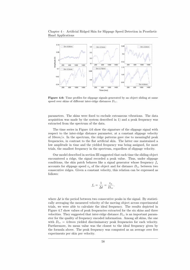
Chapter 4 - Artificial Ridged Skin for Slippage Speed Detection in ProstheticHand Applications
0
0.08
0.16
0.1
0.2
0.3
0.4
Drr=2.5mm
0.54
0.62
0.7
0.8
0.88
200 600 1000 1400
Time [ms]
Am
plit
ud
e [V
]
Drr=3.0mm
Drr=4.0mm
Drr=3.75mmDrr=3.5mm
Drr=0.0mm
0.52
0.6
0.68
0.95
1.05
1.15200 600 1000 1400
200 600 1000 1400
200 600 1000 1400
200 600 1000 1400
200 600 1000 1400
Figure 4.6: Time profiles for slippage signals generated by an object sliding at samespeed over skins of different inter-ridge distances Drr.
parameters. The skins were fixed to exclude extraneous vibrations. The dataacquisition was made by the system described in 1) and a peak frequency wasextracted from the spectrum of the data.
The time series in Figure 4.6 show the signature of the slippage signal withrespect to the inter-ridge distance parameter, at a constant slippage velocityof 10mm/s. In the spectrum, the ridge patterns gave rise to meaningful peakfrequencies, in contrast to the flat artificial skin. The latter one maintained alow amplitude in time and the yielded frequency was being assigned, for mosttrials, the smallest frequency in the spectrum, regardless of slippage velocity.
Our model described in section III suggested that each time the sliding objectencountered a ridge, the signal recorded a peak value. Thus, under slippageconditions, the skin patch behaves like a signal generator whose frequency fsaccounts for slippage speed vo of the object and for distance Drr between twoconsecutive ridges. Given a constant velocity, this relation can be expressed asfollows:
fs =1
∆t=
voDrr
.
where ∆t is the period between two consecutive peaks in the signal. By statisti-cally averaging the measured velocity of the moving object across experimentaltrials, we were able to calculate the ideal frequency. The results depicted inFigure 4.7 show values of peak frequencies extracted for the six skins and threevelocities. They suggested that inter-ridge distance Drr is an important param-eter for the quality of frequency encoded information. Among all skins, the onewith Drr = 4.0mm yielded discriminatory peak frequencies for each velocity.Furthermore, its mean value was the closest to the ideal frequency given bythe formula above. The peak frequency was computed as an average over fiveexperiments per skin per velocity.
58
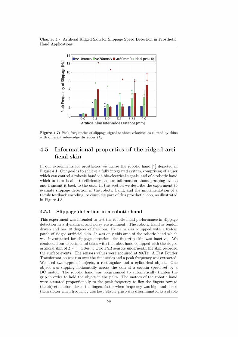
Chapter 4 - Artificial Ridged Skin for Slippage Speed Detection in ProstheticHand Applications
v=10mm/s v=20mm/s v=30mm/s Ideal peak fq.P
eak
Fre
qu
en
cy o
f Sl
ipp
age
[Hz]
0
2
4
6
8
10
12
14
Artificial Skin Inter-ridge Distance [mm]0.0 2.5 3.0 3.5 3.75 4.0
Figure 4.7: Peak frequencies of slippage signal at three velocities as elicited by skinswith different inter-ridge distances Drr.
4.5 Informational properties of the ridged arti-
ficial skin
In our experiments for prosthetics we utilize the robotic hand [7] depicted inFigure 4.1. Our goal is to achieve a fully integrated system, comprising of a userwhich can control a robotic hand via bio-electrical signals, and of a robotic handwhich in turn is able to efficiently acquire information about grasping eventsand transmit it back to the user. In this section we describe the experiment toevaluate slippage detection in the robotic hand, and the implementation of atactile feedback encoding, to complete part of this prosthetic loop, as illustratedin Figure 4.8.
4.5.1 Slippage detection in a robotic hand
This experiment was intended to test the robotic hand performance in slippagedetection in a dynamical and noisy environment. The robotic hand is tendondriven and has 13 degrees of freedom. Its palm was equipped with a 8x4cmpatch of ridged artificial skin. It was only this area of the robotic hand whichwas investigated for slippage detection, the fingertip skin was inactive. Weconducted our experimental trials with the robot hand equipped with the ridgedartificial skin of Drr = 4.0mm. Two FSR sensors underneath the skin recordedthe surface events. The sensors values were acquired at 80Hz. A Fast FourierTransformation was run over the time series and a peak frequency was extracted.We used two types of objects, a rectangular and a cylindrical object. Oneobject was slipping horizontally across the skin at a certain speed set by aDC motor. The robotic hand was programmed to automatically tighten thegrip in order to hold the object in the palm. The motors of the robotic handwere actuated proportionally to the peak frequency to flex the fingers towardthe object: motors flexed the fingers faster when frequency was high and flexedthem slower when frequency was low. Stable grasp was discriminated as a stable
59
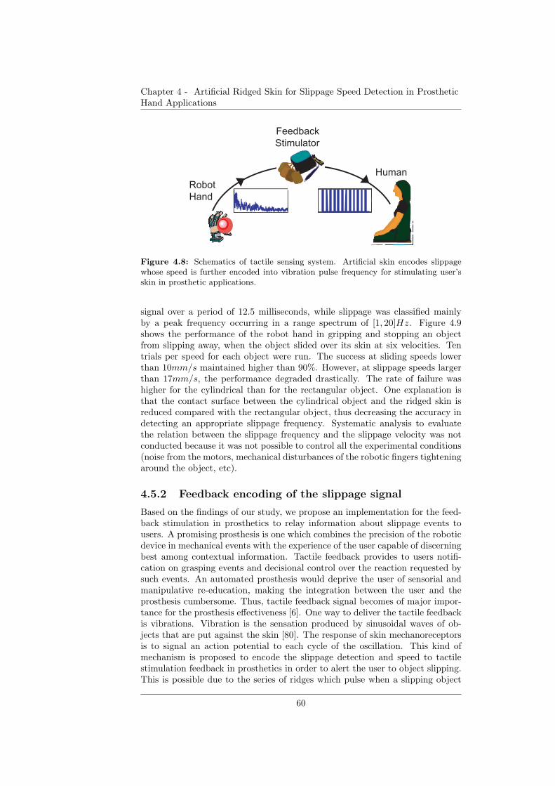
Chapter 4 - Artificial Ridged Skin for Slippage Speed Detection in ProstheticHand Applications
Feedback
Stimulator
Robot
Hand
Human
Figure 4.8: Schematics of tactile sensing system. Artificial skin encodes slippagewhose speed is further encoded into vibration pulse frequency for stimulating user’sskin in prosthetic applications.
signal over a period of 12.5 milliseconds, while slippage was classified mainlyby a peak frequency occurring in a range spectrum of [1, 20]Hz. Figure 4.9shows the performance of the robot hand in gripping and stopping an objectfrom slipping away, when the object slided over its skin at six velocities. Tentrials per speed for each object were run. The success at sliding speeds lowerthan 10mm/s maintained higher than 90%. However, at slippage speeds largerthan 17mm/s, the performance degraded drastically. The rate of failure washigher for the cylindrical than for the rectangular object. One explanation isthat the contact surface between the cylindrical object and the ridged skin isreduced compared with the rectangular object, thus decreasing the accuracy indetecting an appropriate slippage frequency. Systematic analysis to evaluatethe relation between the slippage frequency and the slippage velocity was notconducted because it was not possible to control all the experimental conditions(noise from the motors, mechanical disturbances of the robotic fingers tighteningaround the object, etc).
4.5.2 Feedback encoding of the slippage signal
Based on the findings of our study, we propose an implementation for the feed-back stimulation in prosthetics to relay information about slippage events tousers. A promising prosthesis is one which combines the precision of the roboticdevice in mechanical events with the experience of the user capable of discerningbest among contextual information. Tactile feedback provides to users notifi-cation on grasping events and decisional control over the reaction requested bysuch events. An automated prosthesis would deprive the user of sensorial andmanipulative re-education, making the integration between the user and theprosthesis cumbersome. Thus, tactile feedback signal becomes of major impor-tance for the prosthesis effectiveness [6]. One way to deliver the tactile feedbackis vibrations. Vibration is the sensation produced by sinusoidal waves of ob-jects that are put against the skin [80]. The response of skin mechanoreceptorsis to signal an action potential to each cycle of the oscillation. This kind ofmechanism is proposed to encode the slippage detection and speed to tactilestimulation feedback in prosthetics in order to alert the user to object slipping.This is possible due to the series of ridges which pulse when a slipping object
60
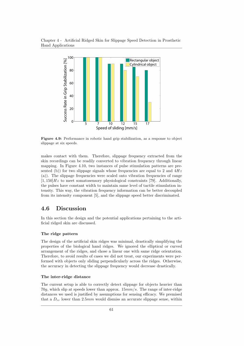
Chapter 4 - Artificial Ridged Skin for Slippage Speed Detection in ProstheticHand Applications
5 7 10 12 15 17 0
20
40
60
80
100
Speed of sliding [mm/s]
Succ
ess
Rat
e in
Gri
p S
tab
iliza
tio
n [%
]
Rectangular objectCylindrical object
Figure 4.9: Performance in robotic hand grip stabilization, as a response to objectslippage at six speeds.
makes contact with them. Therefore, slippage frequency extracted from theskin recordings can be readily converted to vibration frequency through linearmapping. In Figure 4.10, two instances of pulse stimulation patterns are pre-sented (b)) for two slippage signals whose frequencies are equal to 2 and 4Hz(a)). The slippage frequencies were scaled onto vibration frequencies of range[1, 150]Hz to meet somatosensory physiological constraints [79]. Additionally,the pulses have constant width to maintain same level of tactile stimulation in-tensity. This way, the vibration frequency information can be better decoupledfrom its intensity component [5], and the slippage speed better discriminated.
4.6 Discussion
In this section the design and the potential applications pertaining to the arti-ficial ridged skin are discussed.
The ridge pattern
The design of the artificial skin ridges was minimal, drastically simplifying theproperties of the biological hand ridges. We ignored the elliptical or curvedarrangement of the ridges, and chose a linear one with same ridge orientation.Therefore, to avoid results of cases we did not treat, our experiments were per-formed with objects only sliding perpendicularly across the ridges. Otherwise,the accuracy in detecting the slippage frequency would decrease drastically.
The inter-ridge distance
The current setup is able to correctly detect slippage for objects heavier than70g, which slip at speeds lower than approx. 15mm/s. The range of inter-ridgedistances we used is justified by assumptions for sensing efficacy. We premisedthat a Drr lower than 2.5mm would dismiss an accurate slippage sense, within
61

Chapter 4 - Artificial Ridged Skin for Slippage Speed Detection in ProstheticHand Applications
0.61
0.80
0.96
0 20 40 60 800 0.6 1.2 1.8 2.5
0.21
0.66
1.09
0 0.6 1.2 1.8 2.5
1
3
5
1
3
5
a) b)
Time [s] Time [ms]
Fo
rce
[N
]
Am
pli
tud
e [
V]
0 20 40 60 80
Figure 4.10: Feedback stimulation patterns. a) Two slippage signals with frequenciesof 2Hz (top) and 4Hz (bottom). b) Expected stimulation pulses corresponding tosignals in a).
the same trend as the skin with Drr = 2.5mm. However, we hypothesize thatthe skin model can be replicated at smaller scales maintaining the same behaviorif concurrently, the raw sensor it is used with has greater precision. On the otherhand, a skin with Drr greater than 4mm would make the slippage sense morecoarse, taking additional time to compute the FFT and deliver the result infeedback stimulation.
The vibro-tactile feedback
For daily activities in which users are engaged, it is important that they receivenot only on-off event information (on-off contact with objects, on-off slippagedetection) about grasping events, but also continuous information on dynami-cal haptic events (slippage of an object, grasping force changes). We transmitcontinuous slippage by discrete timed events, according to neuroscience find-ings [148] which advocate that the brain responds better to discrete movementsthan to continuous actions. Such discrete stimulation, in contrast to static one,also suffers less from habituation [79]. The quantification of slippage speedwithin the stimulation supports the user perception of a slippage notification oralarm to which he should react with an appropriate grip. Apart from signalingslippage, this specific feedback pattern could also provide the users with mor-phological cues about the robotic device embedded to their body. Ultimately, wehypothesize that exposing the users to such dynamical and relevant informationabout the interaction with the environment would reinforce the incorporationof the robotic device into the body.
4.7 Conclusions
In this study, we showed that a careful consideration of morphology in thedesign of tactile sensing systems can lead to enhanced prosthetic interfaces, withreduced cost on the overall complexity of the prosthetic system. The ridges ofthe artificial skin allowed the encoding of slippage detection and slippage speed
62

Chapter 4 - Artificial Ridged Skin for Slippage Speed Detection in ProstheticHand Applications
quantification into a signal which can be readily postprocessed for feedbackstimulation patterns in prosthetics. As a follow up, an investigation of othermorphologies for the artificial skin, like spiral or concentric circular ridges willtake place. Our preliminary results with circular ridges reveal that we canto an extent extract information about relative position of an object in thehand. Future work will also involve tests with human participants to evaluatethe effectiveness of the proposed stimulation pattern in detecting slippage andadjusting grip.
63

Chapter 4 - Artificial Ridged Skin for Slippage Speed Detection in ProstheticHand Applications
64
Chapter 5
Artificial Tactile Sensing of
Slip Speed and Position
with Minimal ResourcesArtificial ridged skin for detectionof slip occurrence, speed andlocation
In Chapter 5 the capabilities of the artificial ridged skin presented in Chapter 4are extended following the same principles of minimal resource usage.We present an artificial ridged skin based on a single force sensor that detectsthe slip occurrence, speed and position of an object, subject to dynamic events,e.g. slip. The artificial skin features parallel triangular ridges that are arrangedin a non-uniform configuration. An evolutionary algorithm generates an optimaldistribution of ridges in terms of the accuracy and resolution of the slip speedand position detection. Real experiments with skins generated by the evolu-tionary algorithm show a successful detection of slip speed and position for slipspeeds lower than 60 mm/s. Our results introduce the concept of “economicaltactile sensing”, defined as the enhancement of tactile information using mini-mal resources by exploiting the morphology of the artificial skin. The conceptis pertinent in prosthetic applications because it can enable a high ratio of in-formation to resources, and it is promising for robust, light and energy-efficienttactile sensing systems. The presented work points toward design principles forefficient tactile sensing through morphology-based computation.
4Parts of the material in this chapter represent a manuscript in process of submission:D.D. Damian, T. Newton, R. Pfeifer and A.M. Okamura (2012) “Artificial tactile sensing ofslip speed and position with minimal resources” (to be submitted)
65
Chapter 5 - Artificial Tactile Sensing of Slip Speed and Position with MinimalResources
5.1 Related Work
Although humans experience a wide range of sensations, sensory psychophysicswas found to be described by mainly four attributes: location, timing, intensityand modality [80]. Tactile sensing research focuses efforts into developing sen-sors that mimic the functionality of the mechanoreceptors found in the humanbody. Current challenges include both developing sensors that provide the afore-mentioned modes of information and synthesizing these channels of informationinto a coherent and meaningful picture of environmental stimuli. Successfullyimplementing these sensing capabilities into robotic devices, such as robotic orprosthetic hands, would endow robots and prosthetics users with refined graspcontrol and enhanced surfaces exploration.
To date, interesting technologies for artificial sensing have been developed,featuring various transduction methods, arrangement and scale of the sensingelements.
Force sensors have been studied extensively [40] [41] and incorporated intonumerous commercially available products, e.g. force sensing resistors (FSR) [69],QTC-based sensors [21], etc. Furthermore, the research in tactile force sens-ing is currently shifting toward distributed sensors, such as tactile arrays, thatcover a large surface of the robot hand. A few examples include all-body sen-sors [94] [141]. In the latter work, interconnected triangular shapes cover thenon-flat surfaces of robots such as ICub, Nao, and Kaspar. Local chips integrategroups of sensor inputs to reduce the number of wires and to compensate forthe hysteresis and sensor drifts. A force sensor array for fingertips is proposedin [26]. This sensor consists of a matrix structure (24.36×34.9 mm) with 64 sen-sitive sites based on FSR technology. The maximum resolution is about 1 mmand the minimum resolution is about 5 mm. Evaluated on a glove, the forcesensor provides good repeatability and sensitivity, although further research isneeded to address sensor linearity and hysteresis.
Inspired by the variety of multi-modal sensory capabilities of human skinmechanoreceptors, distributed heterogeneous tactile sensors have been devel-oped. Takamuku et al. [150] developed an artificial skin that embeds two typesof sensors (strain gauges and polyvinylidene fluoride (PVDF)) between two sil-icone layers. This skin has been proven to discriminate between a number oftextures during squeezing and tapping. An alternative design for tactile sensorsis presented in [162]. The artificial skin features a rigid core equipped with anarray of electrodes surrounded by a weak conductive fluid. The volumetric flowpath can be differentially measured by each electrode to acquire informationabout force magnitude, direction or object shape.
While force is useful for characterizing grip intensity, in robotic/prosthetichands, slip speed is relevant for characterizing grasp disorders. Johansson andCole [73] offer a prime indication that slip speed may affect our grip response.Slip, artificially generated by changing the weights of an object held in thehuman hand, was found to influence the reaction time and intensity of the gripresponse depending on the weight change ratio. Slip sensing is a prerequisite forstable grasp and fine object manipulation [75] [10]. In a recent haptics study,slip speed has been shown to boost the agility of overcoming slip, increasethe success in controlling slip with a lower consumption of muscle contractionintensity, and ensure lower variability of the muscle contraction input [42].
In robotic grippers, the typical procedure for slip detection is to identify
66
Chapter 5 - Artificial Tactile Sensing of Slip Speed and Position with MinimalResources
extraneous perturbations or patterns of vibrations in the signal. A 18× 18 mmsensor for detecting slip is presented in [103]. Four FSRs placed in differentregions of this surface acquire the position of the force and its activation in timethrough rubber cylinders that cover them and transduce the external force. Cot-ton et al. [38] developed a sensor based on thick-film piezoelectric material shownto detect incipient slip for a friction coefficient of 0.3. In [15], a miniature siliconsensor (1.5 mm ×1.5 mm µm) is composed of four integrated piezoresistors thatare used independently to acquire the three components of an external appliedforce. This sensor was shown to detect slip with a delay from a minimum of24.5 ms to a maximum of 44 ms in the majority of experiments. Optics becomesan additional option in detecting slip. “Tactile” images, defining grasp postures,are processed to determine changes indicating slip. Using conical feelers on thesurface of a rubber sheet, Ohka et al. [112] acquired an image of the contact areaand of the feelers displacement to determine the surface normal and shear forces.Another method for detecting slippage is to consider tactile information as atactile image and use motion detection algorithms [100]. An array of identicalelectrical circuits is sensitive to temporal and spatial changes, and thus can beused to detect microvibrations produced by slip. Currently, sensor technologyprovided qualitative measures of slip, e.g., slip detection, but not quantitative,e.g., slip speed. Tactile arrays contain location information (individual sensoraddressability), and thus slip speed could potentially be detected - nonetheless,this feature has not been given much attention.
Current sensor technologies are primarily concerned with increasing sensingaccuracy and augmenting grasp performance. While this research trend hasvastly improved the design and understanding of sensor arrays in the context ofrobotic grasp, it has done little to address the energy efficiency of these relativelycomplex structures. While the literature offers a plethora of designs and mech-anisms for tactile sensors, few studies discuss the impact of numerous factors,such as the space and number of embedded electronics, distributed computing,networking, integration of sensory data, wiring, crosstalks, robustness, powerconsumption, ease of manufacturing, cost, and maintainability, on the usabil-ity and feasibility of the proposed artificial sensing solution. In particular, thespatial arrangement and the transduction method used in the development oftactile arrays are factors of high concern in a dual quest of high spatial reso-lution and high sensitivity. The amount of wired interconnections associatedwith tactile arrays represents an impediment to dexterity due to the increasedamount of time required to scan and transmit the readings from the array’staxels. Indeed, processing a large amount of data has been considered a majorchallenge in the field of sensor fusion. Although work has been done in the localpre-processing of the data (compensation of temperature and drifts, data pre-selection, etc.) by affixing local microcontrollers, the technological limitationsof data buses hinder the number of taxels that can be used in tactile arraysor efficient computations on the acquired data. The sensory transmission timeimposes another limit on the number of taxels, as the speed of transmissiondepends on the time needed to scan and multiplex the sensor elements of thearray. Power consumption is also a major concern, as for instance in prosthetichands which are expected to function consistently over long periods of time.Clearly, there is a positive correlation between the number of taxels and thepower consumption of the artificial sensory system. A large number of taxelsintrinsically affects the robustness of the system due to the interconnections
67

Chapter 5 - Artificial Tactile Sensing of Slip Speed and Position with MinimalResources
DDDDD D3D1 D4 D5D2
A B
Force sensor
Ridges
Figure 5.1: Arrangement of ridges on the artificial skin equipped with a force sensor.A. Uniform distribution of ridges. B. Non-uniform distribution of ridges. Ds representthe inter-ridge spacing. For the skin in case A, the inter-ridge distances are identical(D).
between the taxels and potential crosstalks. Redundancy could be the positiveflip side of this issue.
Towards the development of efficient tactile systems, our approach to tactilesensing systems is to exploit the structure and the space of the artificial skin’smaterials in order to increase the sensory information at low cost, with respectto design complexity and energy consumption. Our approach was motivated inpart by the work of Vincent et al. [157] and Pfeifer et al. [123] which advocatesthat engineering techniques primarily make use of energy, whereas biologicalsystems primarily exploit structure, space and information. This latter strategycould be incorporated in the development of novel sensors to achieve an optimaltrade off between information density and resource consumption. We presentan artificial skin that detects stimulus slip occurrence and speed, location, andforce (implicitly, due to the use of a force sensor), using a single force sensor.The latter feature, normal force, was investigated in static events in a previouswork [46] and will be ignored in this study. The underlying approach is basedon exploiting a non-uniform arrangement of parallel ridges whose consequence isthe multiplexing of multi-sensory information into one data channel. Enhancinginformation while reducing the underlying resources finds priority especially inprosthetic applications, by reducing the circuitry, and therefore improving thesystem’s robustness, while reducing energy consumption and overall complexity.
5.2 Concept for object slip speed and position
detection
Consider a surface with uniformly distributed ridges (see Fig. 5.1A). A forcetransducer underneath the surface can intercept the force applied by an objectslipping on top of the skin. As the object moves across the surface and hitsa ridge, it gives rise to a peak in the force signal produced by the transducer.Given a constant spacing D and assuming a constant speed, v, we can determinethe slip speed from the relation v = D/T , where T is the time period betweenthe peaks in the force signal [46].
Although the homogeneous pattern of ridges enables the detection of the slipoccurrence and computation of the slip speed, the ridge arrangement does notallow the detection of the dynamic location of the object on the skin surface.As long as the spacings have constant length and the speed is also constant, thetime period between peaks is the same, regardless of where the object is on theskin. One possibility for detecting location is to change the distribution of theridges on the surface of the skin such that the spacing information is a unique
68
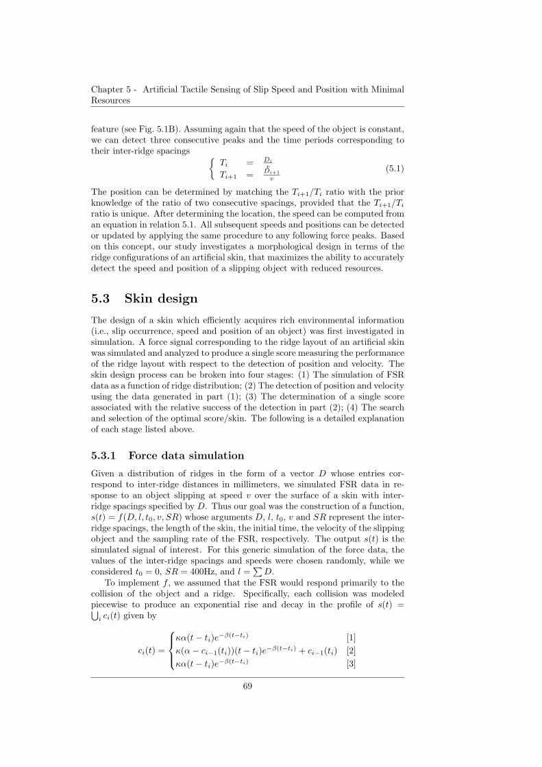
Chapter 5 - Artificial Tactile Sensing of Slip Speed and Position with MinimalResources
feature (see Fig. 5.1B). Assuming again that the speed of the object is constant,we can detect three consecutive peaks and the time periods corresponding totheir inter-ridge spacings
{
Ti = Di
v
Ti+1 = Di+1
v
(5.1)
The position can be determined by matching the Ti+1/Ti ratio with the priorknowledge of the ratio of two consecutive spacings, provided that the Ti+1/Ti
ratio is unique. After determining the location, the speed can be computed froman equation in relation 5.1. All subsequent speeds and positions can be detectedor updated by applying the same procedure to any following force peaks. Basedon this concept, our study investigates a morphological design in terms of theridge configurations of an artificial skin, that maximizes the ability to accuratelydetect the speed and position of a slipping object with reduced resources.
5.3 Skin design
The design of a skin which efficiently acquires rich environmental information(i.e., slip occurrence, speed and position of an object) was first investigated insimulation. A force signal corresponding to the ridge layout of an artificial skinwas simulated and analyzed to produce a single score measuring the performanceof the ridge layout with respect to the detection of position and velocity. Theskin design process can be broken into four stages: (1) The simulation of FSRdata as a function of ridge distribution; (2) The detection of position and velocityusing the data generated in part (1); (3) The determination of a single scoreassociated with the relative success of the detection in part (2); (4) The searchand selection of the optimal score/skin. The following is a detailed explanationof each stage listed above.
5.3.1 Force data simulation
Given a distribution of ridges in the form of a vector D whose entries cor-respond to inter-ridge distances in millimeters, we simulated FSR data in re-sponse to an object slipping at speed v over the surface of a skin with inter-ridge spacings specified by D. Thus our goal was the construction of a function,s(t) = f(D, l, t0, v, SR) whose arguments D, l, t0, v and SR represent the inter-ridge spacings, the length of the skin, the initial time, the velocity of the slippingobject and the sampling rate of the FSR, respectively. The output s(t) is thesimulated signal of interest. For this generic simulation of the force data, thevalues of the inter-ridge spacings and speeds were chosen randomly, while weconsidered t0 = 0, SR = 400Hz, and l =
∑
D.To implement f , we assumed that the FSR would respond primarily to the
collision of the object and a ridge. Specifically, each collision was modeledpiecewise to produce an exponential rise and decay in the profile of s(t) =⋃
i ci(t) given by
ci(t) =
κα(t− ti)e−β(t−ti) [1]
κ(α− ci−1(ti))(t− ti)e−β(t−ti) + ci−1(ti) [2]
κα(t− ti)e−β(t−ti) [3]
69
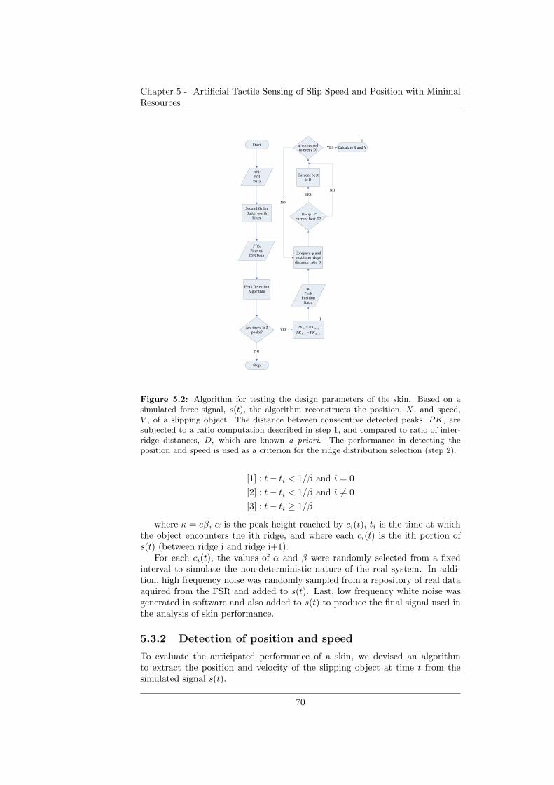
Chapter 5 - Artificial Tactile Sensing of Slip Speed and Position with MinimalResources
�����
�����
��
����
� �������� ��
���� �������
��� �
������
��� � ��
������
� ���� � ������
���������
�� ��� � �� �
! ���"
���!
21
1
−−
−
−−
NN
NN
PKPK
PKPK
#
$�
� ���
���������
����
%��!�� �$�����
� &����� �'���� ��
������� ��������(
)*�
+�
,���- $�,�.�
���� ���/ ����"
)*�
%��� ���/ ���
����
+�
+�
%������� �0�����1
2$����!�� ��
��� 3 �4��")*�
Figure 5.2: Algorithm for testing the design parameters of the skin. Based on asimulated force signal, s(t), the algorithm reconstructs the position, X, and speed,V , of a slipping object. The distance between consecutive detected peaks, PK, aresubjected to a ratio computation described in step 1, and compared to ratio of inter-ridge distances, D, which are known a priori. The performance in detecting theposition and speed is used as a criterion for the ridge distribution selection (step 2).
[1] : t− ti < 1/β and i = 0
[2] : t− ti < 1/β and i 6= 0
[3] : t− ti ≥ 1/β
where κ = eβ, α is the peak height reached by ci(t), ti is the time at whichthe object encounters the ith ridge, and where each ci(t) is the ith portion ofs(t) (between ridge i and ridge i+1).
For each ci(t), the values of α and β were randomly selected from a fixedinterval to simulate the non-deterministic nature of the real system. In addi-tion, high frequency noise was randomly sampled from a repository of real dataaquired from the FSR and added to s(t). Last, low frequency white noise wasgenerated in software and also added to s(t) to produce the final signal used inthe analysis of skin performance.
5.3.2 Detection of position and speed
To evaluate the anticipated performance of a skin, we devised an algorithmto extract the position and velocity of the slipping object at time t from thesimulated signal s(t).
70
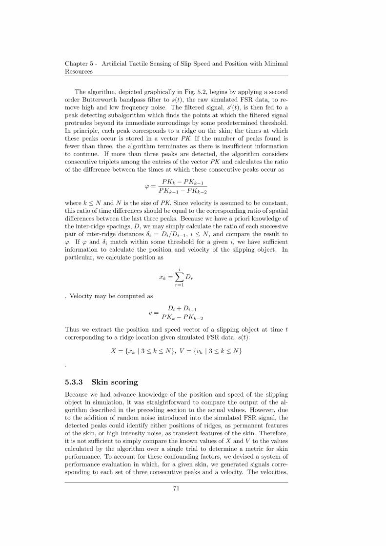
Chapter 5 - Artificial Tactile Sensing of Slip Speed and Position with MinimalResources
The algorithm, depicted graphically in Fig. 5.2, begins by applying a secondorder Butterworth bandpass filter to s(t), the raw simulated FSR data, to re-move high and low frequency noise. The filtered signal, s′(t), is then fed to apeak detecting subalgorithm which finds the points at which the filtered signalprotrudes beyond its immediate surroudings by some predetermined threshold.In principle, each peak corresponds to a ridge on the skin; the times at whichthese peaks occur is stored in a vector PK. If the number of peaks found isfewer than three, the algorithm terminates as there is insufficient informationto continue. If more than three peaks are detected, the algorithm considersconsecutive triplets among the entries of the vector PK and calculates the ratioof the difference between the times at which these consecutive peaks occur as
ϕ =PKk − PKk−1
PKk−1 − PKk−2
where k ≤ N and N is the size of PK. Since velocity is assumed to be constant,this ratio of time differences should be equal to the corresponding ratio of spatialdifferences between the last three peaks. Because we have a priori knowledge ofthe inter-ridge spacings, D, we may simply calculate the ratio of each successivepair of inter-ridge distances δi = Di/Di−1, i ≤ N , and compare the result toϕ. If ϕ and δi match within some threshold for a given i, we have sufficientinformation to calculate the position and velocity of the slipping object. Inparticular, we calculate position as
xk =
i∑
r=1
Dr
. Velocity may be computed as
v =Di +Di−1
PKk − PKk−2
Thus we extract the position and speed vector of a slipping object at time tcorresponding to a ridge location given simulated FSR data, s(t):
X = {xk | 3 ≤ k ≤ N}, V = {vk | 3 ≤ k ≤ N}
.
5.3.3 Skin scoring
Because we had advance knowledge of the position and speed of the slippingobject in simulation, it was straightforward to compare the output of the al-gorithm described in the preceding section to the actual values. However, dueto the addition of random noise introduced into the simulated FSR signal, thedetected peaks could identify either positions of ridges, as permanent featuresof the skin, or high intensity noise, as transient features of the skin. Therefore,it is not sufficient to simply compare the known values of X and V to the valuescalculated by the algorithm over a single trial to determine a metric for skinperformance. To account for these confounding factors, we devised a system ofperformance evaluation in which, for a given skin, we generated signals corre-sponding to each set of three consecutive peaks and a velocity. The velocities,
71
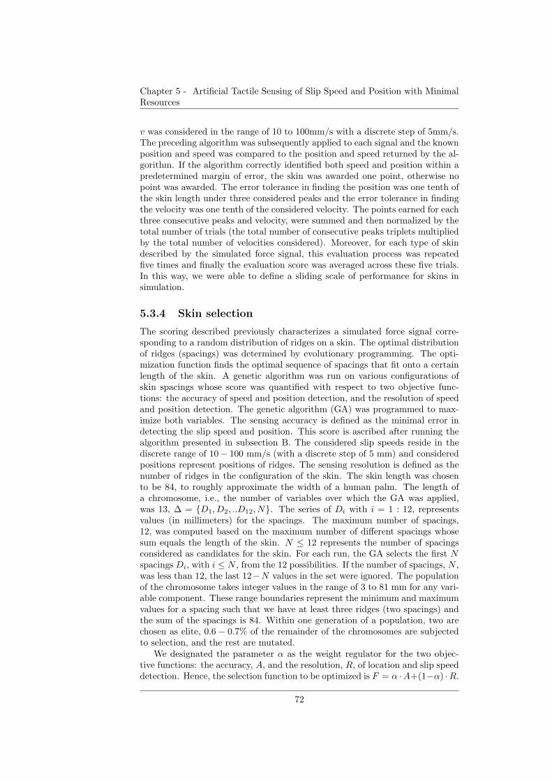
Chapter 5 - Artificial Tactile Sensing of Slip Speed and Position with MinimalResources
v was considered in the range of 10 to 100mm/s with a discrete step of 5mm/s.The preceding algorithm was subsequently applied to each signal and the knownposition and speed was compared to the position and speed returned by the al-gorithm. If the algorithm correctly identified both speed and position within apredetermined margin of error, the skin was awarded one point, otherwise nopoint was awarded. The error tolerance in finding the position was one tenth ofthe skin length under three considered peaks and the error tolerance in findingthe velocity was one tenth of the considered velocity. The points earned for eachthree consecutive peaks and velocity, were summed and then normalized by thetotal number of trials (the total number of consecutive peaks triplets multipliedby the total number of velocities considered). Moreover, for each type of skindescribed by the simulated force signal, this evaluation process was repeatedfive times and finally the evaluation score was averaged across these five trials.In this way, we were able to define a sliding scale of performance for skins insimulation.
5.3.4 Skin selection
The scoring described previously characterizes a simulated force signal corre-sponding to a random distribution of ridges on a skin. The optimal distributionof ridges (spacings) was determined by evolutionary programming. The opti-mization function finds the optimal sequence of spacings that fit onto a certainlength of the skin. A genetic algorithm was run on various configurations ofskin spacings whose score was quantified with respect to two objective func-tions: the accuracy of speed and position detection, and the resolution of speedand position detection. The genetic algorithm (GA) was programmed to max-imize both variables. The sensing accuracy is defined as the minimal error indetecting the slip speed and position. This score is ascribed after running thealgorithm presented in subsection B. The considered slip speeds reside in thediscrete range of 10− 100 mm/s (with a discrete step of 5 mm) and consideredpositions represent positions of ridges. The sensing resolution is defined as thenumber of ridges in the configuration of the skin. The skin length was chosento be 84, to roughly approximate the width of a human palm. The length ofa chromosome, i.e., the number of variables over which the GA was applied,was 13, ∆ = {D1, D2, ..D12, N}. The series of Di with i = 1 : 12, representsvalues (in millimeters) for the spacings. The maximum number of spacings,12, was computed based on the maximum number of different spacings whosesum equals the length of the skin. N ≤ 12 represents the number of spacingsconsidered as candidates for the skin. For each run, the GA selects the first Nspacings Di, with i ≤ N , from the 12 possibilities. If the number of spacings, N ,was less than 12, the last 12−N values in the set were ignored. The populationof the chromosome takes integer values in the range of 3 to 81 mm for any vari-able component. These range boundaries represent the minimum and maximumvalues for a spacing such that we have at least three ridges (two spacings) andthe sum of the spacings is 84. Within one generation of a population, two arechosen as elite, 0.6 − 0.7% of the remainder of the chromosomes are subjectedto selection, and the rest are mutated.
We designated the parameter α as the weight regulator for the two objec-tive functions: the accuracy, A, and the resolution, R, of location and slip speeddetection. Hence, the selection function to be optimized is F = α ·A+(1−α) ·R.
72
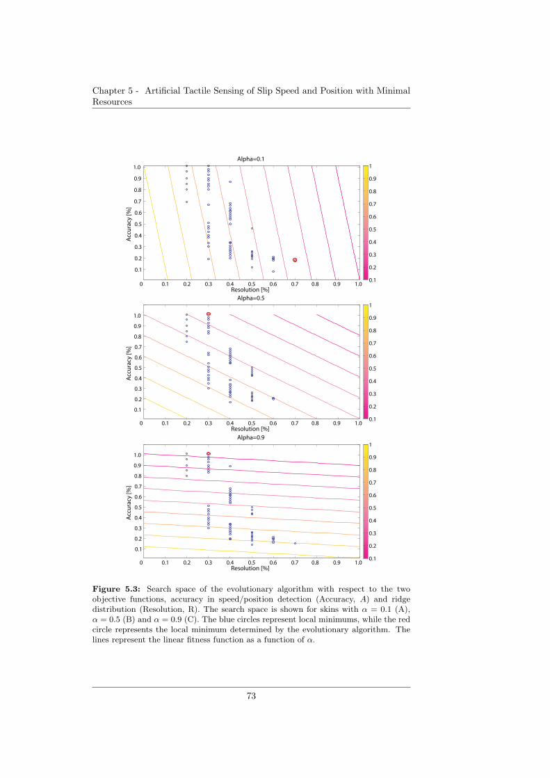
Chapter 5 - Artificial Tactile Sensing of Slip Speed and Position with MinimalResources
Resolution [%]
Acc
ura
cy [%
]
Alpha=0.5
0 0.1 0.2 0.3 0.4 0.5 0.6 0.7 0.8 0.9 1.0
0.1
0.2
0.3
0.4
0.5
0.6
0.7
0.8
0.9
1.0
0.1
0.2
0.3
0.4
0.5
0.6
0.7
0.8
0.9
1
Resolution [%]
Acc
ura
cy [%
]
Alpha=0.9
0 0.1 0.2 0.3 0.4 0.5 0.6 0.7 0.8 0.9 1.0
0.1
0.2
0.3
0.4
0.5
0.6
0.7
0.8
0.9
1.0
0.1
0.2
0.3
0.4
0.5
0.6
0.7
0.8
0.9
1
Resolution [%]
Acc
ura
cy [%
]
Alpha=0.1
0 0.1 0.2 0.3 0.4 0.5 0.6 0.7 0.8 0.9 1.0
0.1
0.2
0.3
0.4
0.5
0.6
0.7
0.8
0.9
1.0
0.1
0.2
0.3
0.4
0.5
0.6
0.7
0.8
0.9
1
Figure 5.3: Search space of the evolutionary algorithm with respect to the twoobjective functions, accuracy in speed/position detection (Accuracy, A) and ridgedistribution (Resolution, R). The search space is shown for skins with α = 0.1 (A),α = 0.5 (B) and α = 0.9 (C). The blue circles represent local minimums, while the redcircle represents the local minimum determined by the evolutionary algorithm. Thelines represent the linear fitness function as a function of α.
73
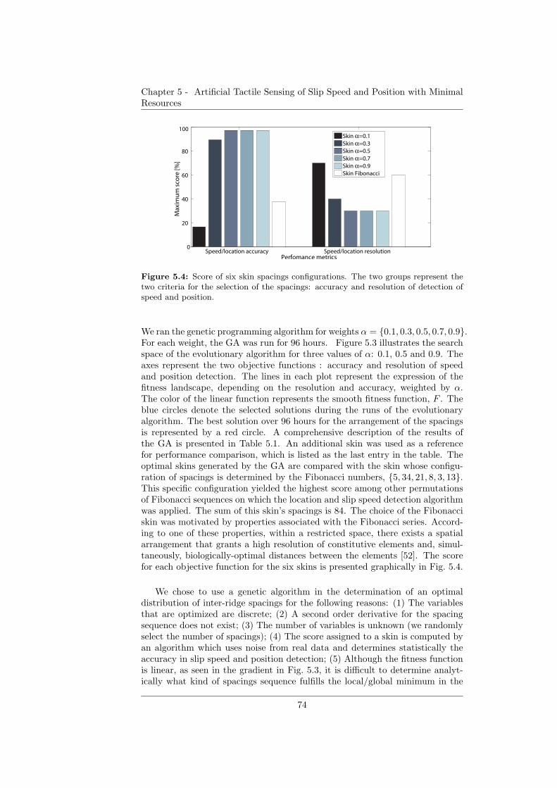
Chapter 5 - Artificial Tactile Sensing of Slip Speed and Position with MinimalResources
Speed/location accuracy Speed/location resolution0
20
40
60
80
100
Perfomance metrics
Max
imu
m s
core
[%]
Skin α=0.1Skin α=0.3Skin α=0.5Skin α=0.7Skin α=0.9Skin Fibonacci
Figure 5.4: Score of six skin spacings configurations. The two groups represent thetwo criteria for the selection of the spacings: accuracy and resolution of detection ofspeed and position.
We ran the genetic programming algorithm for weights α = {0.1, 0.3, 0.5, 0.7, 0.9}.For each weight, the GA was run for 96 hours. Figure 5.3 illustrates the searchspace of the evolutionary algorithm for three values of α: 0.1, 0.5 and 0.9. Theaxes represent the two objective functions : accuracy and resolution of speedand position detection. The lines in each plot represent the expression of thefitness landscape, depending on the resolution and accuracy, weighted by α.The color of the linear function represents the smooth fitness function, F . Theblue circles denote the selected solutions during the runs of the evolutionaryalgorithm. The best solution over 96 hours for the arrangement of the spacingsis represented by a red circle. A comprehensive description of the results ofthe GA is presented in Table 5.1. An additional skin was used as a referencefor performance comparison, which is listed as the last entry in the table. Theoptimal skins generated by the GA are compared with the skin whose configu-ration of spacings is determined by the Fibonacci numbers, {5, 34, 21, 8, 3, 13}.This specific configuration yielded the highest score among other permutationsof Fibonacci sequences on which the location and slip speed detection algorithmwas applied. The sum of this skin’s spacings is 84. The choice of the Fibonacciskin was motivated by properties associated with the Fibonacci series. Accord-ing to one of these properties, within a restricted space, there exists a spatialarrangement that grants a high resolution of constitutive elements and, simul-taneously, biologically-optimal distances between the elements [52]. The scorefor each objective function for the six skins is presented graphically in Fig. 5.4.
We chose to use a genetic algorithm in the determination of an optimaldistribution of inter-ridge spacings for the following reasons: (1) The variablesthat are optimized are discrete; (2) A second order derivative for the spacingsequence does not exist; (3) The number of variables is unknown (we randomlyselect the number of spacings); (4) The score assigned to a skin is computed byan algorithm which uses noise from real data and determines statistically theaccuracy in slip speed and position detection; (5) Although the fitness functionis linear, as seen in the gradient in Fig. 5.3, it is difficult to determine analyt-ically what kind of spacings sequence fulfills the local/global minimum in the
74
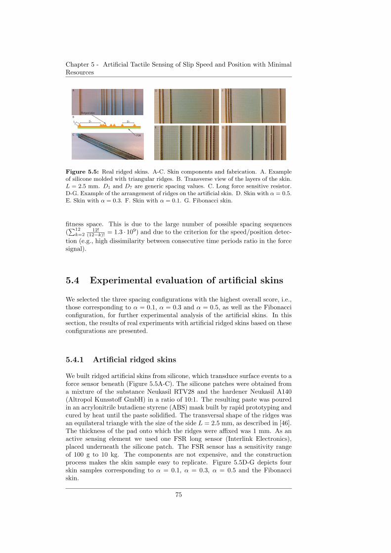
Chapter 5 - Artificial Tactile Sensing of Slip Speed and Position with MinimalResources
D1L D7
FSR
Ridged skin
A
B
C
D F
E G
Figure 5.5: Real ridged skins. A-C. Skin components and fabrication. A. Exampleof silicone molded with triangular ridges. B. Transverse view of the layers of the skin.L = 2.5 mm. D1 and D7 are generic spacing values. C. Long force sensitive resistor.D-G. Example of the arrangement of ridges on the artificial skin. D. Skin with α = 0.5.E. Skin with α = 0.3. F. Skin with α = 0.1. G. Fibonacci skin.
fitness space. This is due to the large number of possible spacing sequences(∑12
k=212!
(12−k)! = 1.3 · 109) and due to the criterion for the speed/position detec-
tion (e.g., high dissimilarity between consecutive time periods ratio in the forcesignal).
5.4 Experimental evaluation of artificial skins
We selected the three spacing configurations with the highest overall score, i.e.,those corresponding to α = 0.1, α = 0.3 and α = 0.5, as well as the Fibonacciconfiguration, for further experimental analysis of the artificial skins. In thissection, the results of real experiments with artificial ridged skins based on theseconfigurations are presented.
5.4.1 Artificial ridged skins
We built ridged artificial skins from silicone, which transduce surface events to aforce sensor beneath (Figure 5.5A-C). The silicone patches were obtained froma mixture of the substance Neukasil RTV28 and the hardener Neukasil A140(Altropol Kunsstoff GmbH) in a ratio of 10:1. The resulting paste was pouredin an acrylonitrile butadiene styrene (ABS) mask built by rapid prototyping andcured by heat until the paste solidified. The transversal shape of the ridges wasan equilateral triangle with the size of the side L = 2.5 mm, as described in [46].The thickness of the pad onto which the ridges were affixed was 1 mm. As anactive sensing element we used one FSR long sensor (Interlink Electronics),placed underneath the silicone patch. The FSR sensor has a sensitivity rangeof 100 g to 10 kg. The components are not expensive, and the constructionprocess makes the skin sample easy to replicate. Figure 5.5D-G depicts fourskin samples corresponding to α = 0.1, α = 0.3, α = 0.5 and the Fibonacciskin.
75
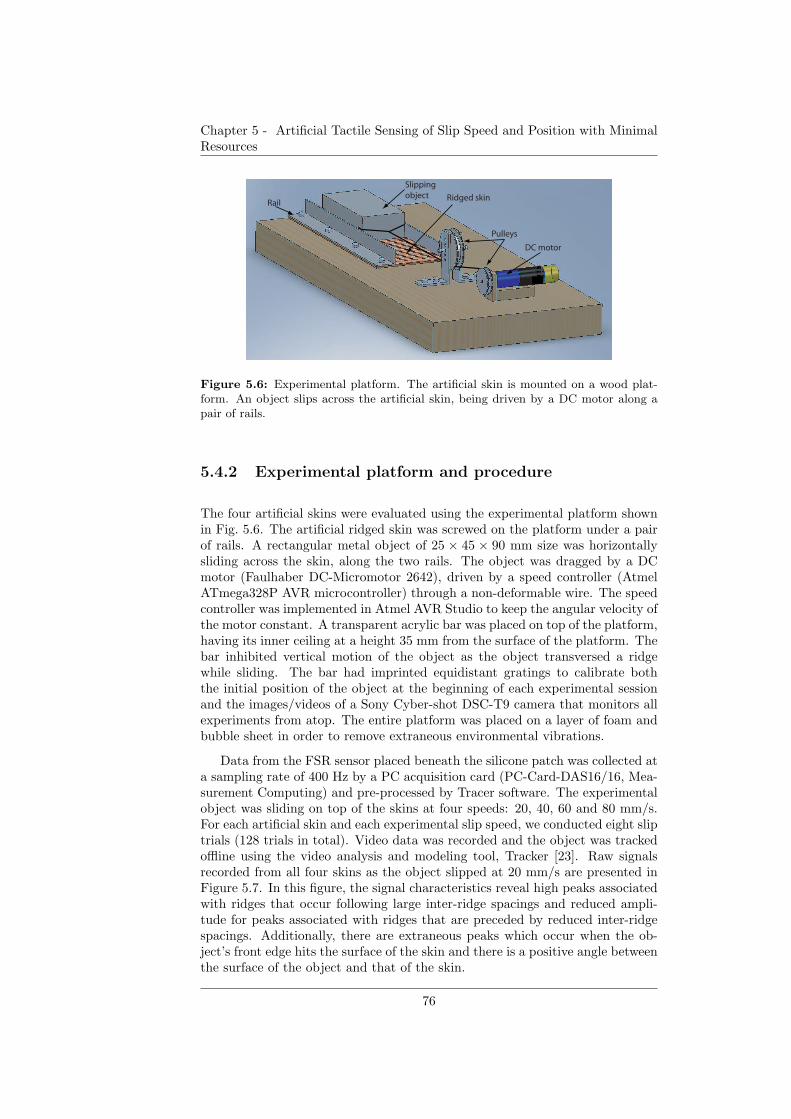
Chapter 5 - Artificial Tactile Sensing of Slip Speed and Position with MinimalResources
Slipping
object Ridged skin
DC motor
Pulleys
Rail
Figure 5.6: Experimental platform. The artificial skin is mounted on a wood plat-form. An object slips across the artificial skin, being driven by a DC motor along apair of rails.
5.4.2 Experimental platform and procedure
The four artificial skins were evaluated using the experimental platform shownin Fig. 5.6. The artificial ridged skin was screwed on the platform under a pairof rails. A rectangular metal object of 25 × 45 × 90 mm size was horizontallysliding across the skin, along the two rails. The object was dragged by a DCmotor (Faulhaber DC-Micromotor 2642), driven by a speed controller (AtmelATmega328P AVR microcontroller) through a non-deformable wire. The speedcontroller was implemented in Atmel AVR Studio to keep the angular velocity ofthe motor constant. A transparent acrylic bar was placed on top of the platform,having its inner ceiling at a height 35 mm from the surface of the platform. Thebar inhibited vertical motion of the object as the object transversed a ridgewhile sliding. The bar had imprinted equidistant gratings to calibrate boththe initial position of the object at the beginning of each experimental sessionand the images/videos of a Sony Cyber-shot DSC-T9 camera that monitors allexperiments from atop. The entire platform was placed on a layer of foam andbubble sheet in order to remove extraneous environmental vibrations.
Data from the FSR sensor placed beneath the silicone patch was collected ata sampling rate of 400 Hz by a PC acquisition card (PC-Card-DAS16/16, Mea-surement Computing) and pre-processed by Tracer software. The experimentalobject was sliding on top of the skins at four speeds: 20, 40, 60 and 80 mm/s.For each artificial skin and each experimental slip speed, we conducted eight sliptrials (128 trials in total). Video data was recorded and the object was trackedoffline using the video analysis and modeling tool, Tracker [23]. Raw signalsrecorded from all four skins as the object slipped at 20 mm/s are presented inFigure 5.7. In this figure, the signal characteristics reveal high peaks associatedwith ridges that occur following large inter-ridge spacings and reduced ampli-tude for peaks associated with ridges that are preceded by reduced inter-ridgespacings. Additionally, there are extraneous peaks which occur when the ob-ject’s front edge hits the surface of the skin and there is a positive angle betweenthe surface of the object and that of the skin.
76
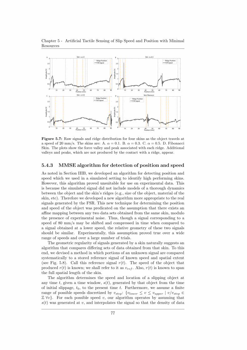
Chapter 5 - Artificial Tactile Sensing of Slip Speed and Position with MinimalResources
10 20 30 40 50 60 70 80 900
0.5
1
1.5
2
2.5
3
Position [mm]
Am
plit
ud
e [V
]
Skin α=0.1
Ridge PositionFSR Signal
10 20 30 40 50 60 70 80 900
0.5
1
1.5
2
2.5
3
Position [mm]
Am
plit
ud
e [V
]
Skin α=0.3
Ridge PositionFSR Signal
10 20 30 40 50 60 70 80 900
0.5
1
1.5
2
2.5
3
Position [mm]
Am
plit
ud
e [V
]
Skin α=0.5
Ridge PositionFSR Signal
10 20 30 40 50 60 70 80 900
0.5
1
1.5
2
2.5
3
Position [mm]
Am
plit
ud
e [V
]
Skin Fibonacci
Ridge PositionFSR Signal
A B
C D
Figure 5.7: Raw signals and ridge distribution for four skins as the object travels ata speed of 20 mm/s. The skins are: A. α = 0.1. B. α = 0.3. C. α = 0.5. D. FibonacciSkin. The plots show the force valley and peak associated with each ridge. Additionalvalleys and peaks, which are not produced by the contact with a ridge, appear.
5.4.3 MMSE algorithm for detection of position and speed
As noted in Section IIIB, we developed an algorithm for detecting position andspeed which we used in a simulated setting to identify high performing skins.However, this algorithm proved unsuitable for use on experimental data. Thisis because the simulated signal did not include models of a thorough dynamicsbetween the object and the skin’s ridges (e.g., size of the object, material of theskin, etc). Therefore we developed a new algorithm more appropriate to the realsignals generated by the FSR. This new technique for determining the positionand speed of the object was predicated on the assumption that there exists anaffine mapping between any two data sets obtained from the same skin, modulothe presence of experimental noise. Thus, though a signal corresponding to aspeed of 80 mm/s may be shifted and compressed in time when compared toa signal obtained at a lower speed, the relative geometry of these two signalsshould be similar. Experimentally, this assumption proved true over a widerange of speeds and over a large number of trials.
The geometric regularity of signals generated by a skin naturally suggests analgorithm that compares differing sets of data obtained from that skin. To thisend, we devised a method in which portions of an unknown signal are comparedsystematically to a stored reference signal of known speed and spatial extent(see Fig. 5.8). Call this reference signal r(t). The speed of the object thatproduced r(t) is known; we shall refer to it as vref . Also, r(t) is known to spanthe full spatial length of the skin.
The algorithm determines the speed and location of a slipping object atany time t, given a time window, s(t), generated by that object from the timeof initial slippage, t0, to the present time t. Furthermore, we assume a finiterange of possible speeds discretized by vstep: {vlower ≤ v ≤ vupper | v/vstep ∈Z ∀v}. For each possible speed v, our algorithm operates by assuming thats(t) was generated at v, and interpolates the signal so that the density of data
77
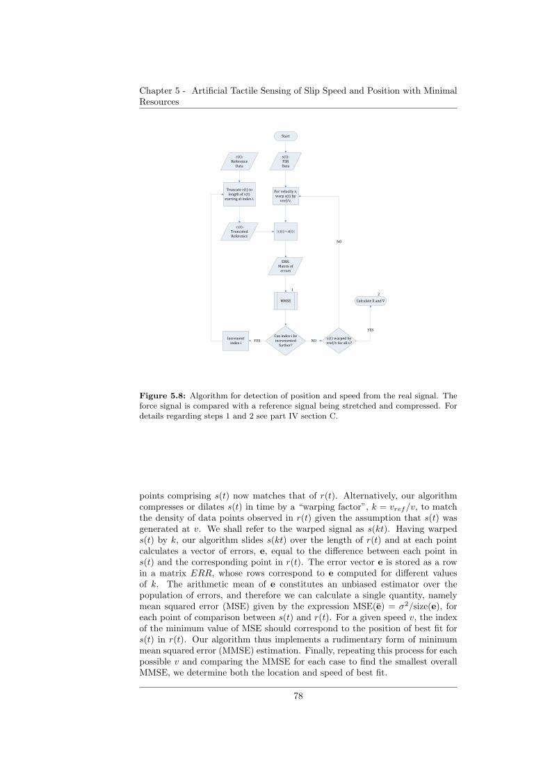
Chapter 5 - Artificial Tactile Sensing of Slip Speed and Position with MinimalResources
�����
���
���
�� ����������
�� �������
� �����
����
���� ����
���
� ������ �����
������������
��� �������� �!��
�
� ������
���� ����
)(tri
|)()(| tstri −
"���
#�� �!��
� � �
##�"
$
%���� �!���
��� �&����
�� ��� '
(�� �&���
�� �!�)"�
��� �
������ �� ��
� ������ ����'*+
*+
%��������,�� -
)"�
.
Figure 5.8: Algorithm for detection of position and speed from the real signal. Theforce signal is compared with a reference signal being stretched and compressed. Fordetails regarding steps 1 and 2 see part IV section C.
points comprising s(t) now matches that of r(t). Alternatively, our algorithmcompresses or dilates s(t) in time by a “warping factor”, k = vref/v, to matchthe density of data points observed in r(t) given the assumption that s(t) wasgenerated at v. We shall refer to the warped signal as s(kt). Having warpeds(t) by k, our algorithm slides s(kt) over the length of r(t) and at each pointcalculates a vector of errors, e, equal to the difference between each point ins(t) and the corresponding point in r(t). The error vector e is stored as a rowin a matrix ERR, whose rows correspond to e computed for different valuesof k. The arithmetic mean of e constitutes an unbiased estimator over thepopulation of errors, and therefore we can calculate a single quantity, namelymean squared error (MSE) given by the expression MSE(e) = σ2/size(e), foreach point of comparison between s(t) and r(t). For a given speed v, the indexof the minimum value of MSE should correspond to the position of best fit fors(t) in r(t). Our algorithm thus implements a rudimentary form of minimummean squared error (MMSE) estimation. Finally, repeating this process for eachpossible v and comparing the MMSE for each case to find the smallest overallMMSE, we determine both the location and speed of best fit.
78
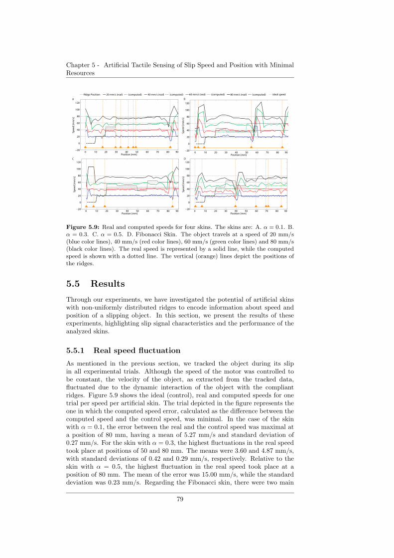
Chapter 5 - Artificial Tactile Sensing of Slip Speed and Position with MinimalResources
0 10 20 30 40 50 60 70 80 90−20
0
20
40
60
80
100
120
Position [mm]
Speed [mm/s]
0 10 20 30 40 50 60 70 80 90−20
0
20
40
60
80
100
120
Position [mm]
Speed [mm/s]
0 10 20 30 40 50 60 70 80 90−20
0
20
40
60
80
100
120
Position [mm]
Speed [mm/s]
Ridge Position 20 mm/s (real) (computed) 40 mm/s (real) (computed) 60 mm/s (real) (computed) 80 mm/s (real) (computed) ideal speed
A B
C D
0 10 20 30 40 50 60 70 80 90−20
0
20
40
60
80
100
120
Position [mm]
Speed [mm/s]
Figure 5.9: Real and computed speeds for four skins. The skins are: A. α = 0.1. B.α = 0.3. C. α = 0.5. D. Fibonacci Skin. The object travels at a speed of 20 mm/s(blue color lines), 40 mm/s (red color lines), 60 mm/s (green color lines) and 80 mm/s(black color lines). The real speed is represented by a solid line, while the computedspeed is shown with a dotted line. The vertical (orange) lines depict the positions ofthe ridges.
5.5 Results
Through our experiments, we have investigated the potential of artificial skinswith non-uniformly distributed ridges to encode information about speed andposition of a slipping object. In this section, we present the results of theseexperiments, highlighting slip signal characteristics and the performance of theanalyzed skins.
5.5.1 Real speed fluctuation
As mentioned in the previous section, we tracked the object during its slipin all experimental trials. Although the speed of the motor was controlled tobe constant, the velocity of the object, as extracted from the tracked data,fluctuated due to the dynamic interaction of the object with the compliantridges. Figure 5.9 shows the ideal (control), real and computed speeds for onetrial per speed per artificial skin. The trial depicted in the figure represents theone in which the computed speed error, calculated as the difference between thecomputed speed and the control speed, was minimal. In the case of the skinwith α = 0.1, the error between the real and the control speed was maximal ata position of 80 mm, having a mean of 5.27 mm/s and standard deviation of0.27 mm/s. For the skin with α = 0.3, the highest fluctuations in the real speedtook place at positions of 50 and 80 mm. The means were 3.60 and 4.87 mm/s,with standard deviations of 0.42 and 0.29 mm/s, respectively. Relative to theskin with α = 0.5, the highest fluctuation in the real speed took place at aposition of 80 mm. The mean of the error was 15.00 mm/s, while the standarddeviation was 0.23 mm/s. Regarding the Fibonacci skin, there were two main
79
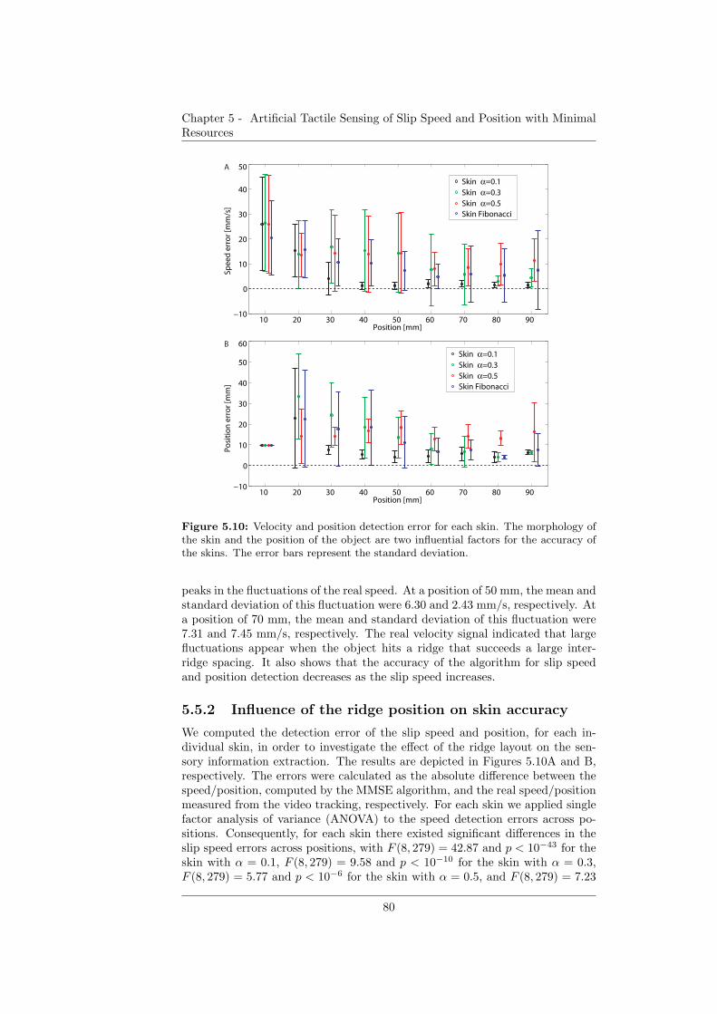
Chapter 5 - Artificial Tactile Sensing of Slip Speed and Position with MinimalResources
10 20 30 40 50 60 70 80 90 −10
0
10
20
30
40
50
Position [mm]
Spe
ed
err
or
[mm
/s]
Skin α=0.1
Skin α=0.3
Skin α=0.5
Skin Fibonacci
10 20 30 40 50 60 70 80 90 −10
0
10
20
30
40
50
60
Position [mm]
Po
siti
on
err
or
[mm
]
Skin α=0.1
Skin α=0.3
Skin α=0.5
Skin Fibonacci
A
B
Figure 5.10: Velocity and position detection error for each skin. The morphology ofthe skin and the position of the object are two influential factors for the accuracy ofthe skins. The error bars represent the standard deviation.
peaks in the fluctuations of the real speed. At a position of 50 mm, the mean andstandard deviation of this fluctuation were 6.30 and 2.43 mm/s, respectively. Ata position of 70 mm, the mean and standard deviation of this fluctuation were7.31 and 7.45 mm/s, respectively. The real velocity signal indicated that largefluctuations appear when the object hits a ridge that succeeds a large inter-ridge spacing. It also shows that the accuracy of the algorithm for slip speedand position detection decreases as the slip speed increases.
5.5.2 Influence of the ridge position on skin accuracy
We computed the detection error of the slip speed and position, for each in-dividual skin, in order to investigate the effect of the ridge layout on the sen-sory information extraction. The results are depicted in Figures 5.10A and B,respectively. The errors were calculated as the absolute difference between thespeed/position, computed by the MMSE algorithm, and the real speed/positionmeasured from the video tracking, respectively. For each skin we applied singlefactor analysis of variance (ANOVA) to the speed detection errors across po-sitions. Consequently, for each skin there existed significant differences in theslip speed errors across positions, with F (8, 279) = 42.87 and p < 10−43 for theskin with α = 0.1, F (8, 279) = 9.58 and p < 10−10 for the skin with α = 0.3,F (8, 279) = 5.77 and p < 10−6 for the skin with α = 0.5, and F (8, 279) = 7.23
80
Chapter 5 - Artificial Tactile Sensing of Slip Speed and Position with MinimalResources
and p < 10−7 for the Fibonacci skin. The Tukey ad hoc test was performedsubsequently. For each type of skin, the speed errors at position 10 mm weresignificantly larger than those at all other positions. In particular, in the caseof the skin with α = 0.1, the speed errors at position 20 mm were significantlylarger than those at all other positions. For the skin with α = 0.3, speed er-rors at position 70 mm were significantly lower than those at position 30 mm.Additionally speed errors at position 80 mm were significantly lower than thoseat positions 20 to 50 mm. Also, these errors recorded at position 90 mm weresignificantly lower than those at positions 30 and 40 mm. For the Fibonacciskin, the speed errors at position 20mm was significantly larger than those atpositions 50 to 80 mm.
Similarly, single factor ANOVA applied to position detection errors con-firmed that significant differences exist between these errors across all posi-tions, with F (8, 279) = 16.18 and p < 10−18 for the skin with α = 0.1,F (8, 279) = 25.17 and p < 10−28 for the skin with α = 0.3, F (8, 279) = 3.03and p < 10−2 for the skin with α = 0.5, and F (8, 279) = 7.71 and p < 10−8 forthe Fibonacci skin. According to the Tukey ad hoc test applied to the skin withα = 0.1, the position errors at position 10 mm were significantly lower thanthese types of errors at position 20 mm, whereas these errors at position 20 mmwere significantly larger than at all other positions. The same test applied tothe skin with α = 0.3 indicated that position errors at position 10 mm weresignificantly lower than those at positions 20 to 40 mm. Moreover, these errorsat position 20 mm were considerably larger than those at positions 30 to 90 mm,errors at position 30 mm were considerably larger than those at positions 50 to90 mm, errors at position 40 mm were considerably larger than those at posi-tions 60 to 90 mm, and lastly, position 50 mm gave raise to considerably largererrors than those at position 80 mm. For the skin with α = 0.5, there werelower position errors at position 10 mm than at positions 40, 50 and 90 mm.In the case of the Fibonacci skin, there were lower position errors at position10 mm than at positions 20 mm. Furthermore, these errors at position 20 mmwere considerably larger than those at positions 50 to 90 mm, errors at each po-sitions of 30 mm and 40 mm were considerably larger than those at positions 60to 90 mm. These results indicate two factors that may influence the accuracy ofdetecting slip speed and position. One is the number of samples that are avail-able for computing speed and position. The errors in detecting either speed orposition were generally smaller as the number of signal samples increases. Thisfactor is analyzed in more detail in a following subsection. A second factor maybe the distribution of the ridges on the artificial skin. As results from the Tukeytests and shown in Figures 5.10AB, large errors in speed and position detectionappeared in the skin with α = 0.1 at position 20 mm, which follows a regionwhere no ridges are present. Similarly, large speed and position errors weremore predominant between positions 20 and 50 mm of the skin with α = 0.3,where no ridge-like feature was present, than between positions 60 and 90 mm.Notably for the skin with α = 0.5, large position detection errors occurred be-tween positions 40 and 50 mm. Given that the largest inter-ridge space liesbetween approximately 20 and 80 mm, the absence of large speed or positionerrors in the region 50 to 80 mm might be attributed to the force fluctuations,which consistently appeared after the object hits the flat surface of the skin withits front edge at an angle. In the case of the Fibonacci skin, large speed andposition errors are found more predominantly between positions 20 and 40 mm
81
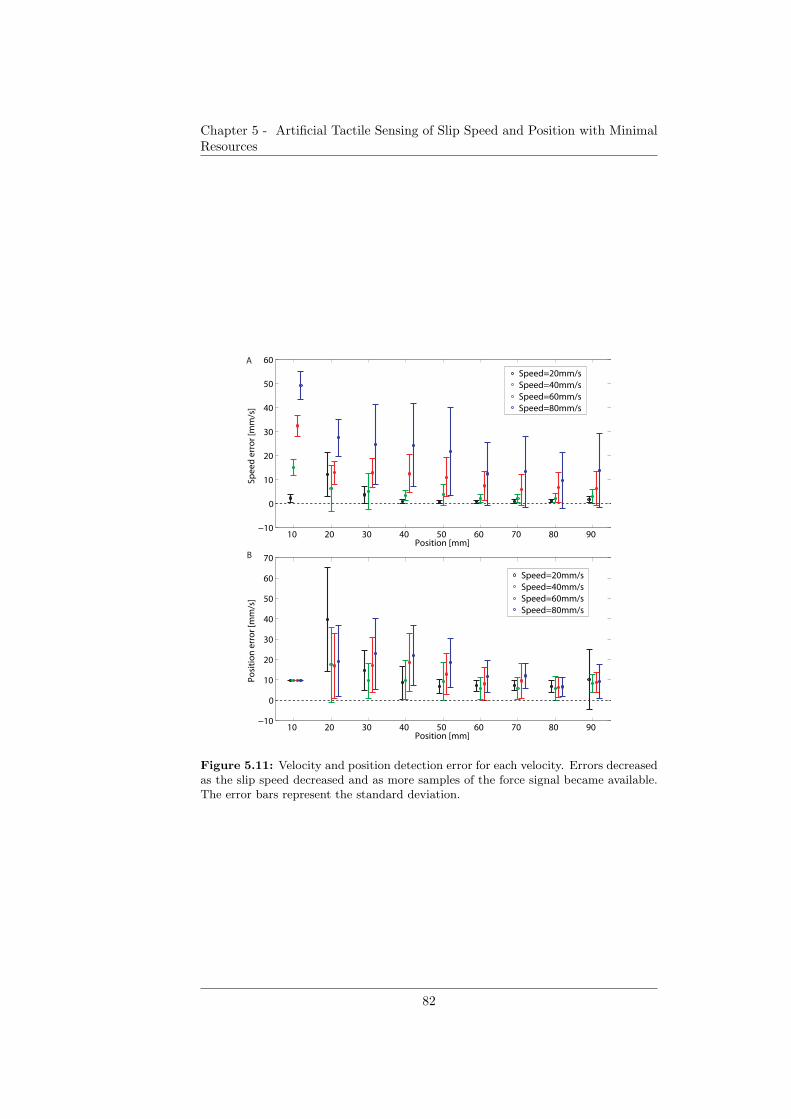
Chapter 5 - Artificial Tactile Sensing of Slip Speed and Position with MinimalResources
10 20 30 40 50 60 70 80 90 −10
0
10
20
30
40
50
60
Position [mm]
Spe
ed
err
or
[mm
/s]
Speed=20mm/sSpeed=40mm/sSpeed=60mm/sSpeed=80mm/s
10 20 30 40 50 60 70 80 90 −10
0
10
20
30
40
50
60
70
Position [mm]
Po
siti
on
err
or
[mm
/s]
Speed=20mm/sSpeed=40mm/sSpeed=60mm/sSpeed=80mm/s
B
A
Figure 5.11: Velocity and position detection error for each velocity. Errors decreasedas the slip speed decreased and as more samples of the force signal became available.The error bars represent the standard deviation.
82
Chapter 5 - Artificial Tactile Sensing of Slip Speed and Position with MinimalResources
than between positions 50 and 90 mm, where the ridges are more dense.
5.5.3 Influence of the speed on skin accuracy
The detection error of slip speed and object position for all skins at each speed isdepicted in Figures 5.11A and B, respectively. The errors are calculated as theabsolute difference between the speed/position, computed by the MMSE algo-rithm, and the real speed/position, measured from the video tracking. Firstly,the influence of the speed values, regardless of the slipping object position, wasanalyzed. Single factor ANOVA applied over the speed error measurementsof all four types of skins across the speeds yielded F (3, 1148) = 179.36 andp < 10−94, indicating that there is a significant difference between the speeddetection performance depending on the slip speed value. The Tukey ad hocmethod showed that significant differences in speed detection performance ap-pear across speeds. In particular, there are significantly larger speed errors atspeed 40 mm/s than those at all other speeds. Similarly, speed errors are con-siderably larger at speed 30 mm/s than those at all other speeds. Similarly,single factor ANOVA applied over the position error measurements of all fourtypes of skins across the speeds yielded F (3, 1148) = 10.44 and p < 10−6. TheTukey ad hoc test showed that position errors at speed 20 mm/s were signifi-cantly lower than those at all other speeds. Also, there were significantly lowerposition errors present at speed 30mm/s than at speed 40mm/s. In summary,the results show that the errors in speed detection increase with the slip speed.
5.5.4 Influence of slip distance on skin accuracy
We investigated the variation of error as the object slip distance increases. Theabsolute speed and position errors were computed over the distances 10−30 mm,40−60 mm and 70−90 mm and both single factor ANOVA and Tukey test wasapplied across these three distances. ANOVA applied to speed errors regardlessof the type of skin and speed yielded F (2, 1149) = 87.65 and p < 10−35, whileANOVA applied to position errors in the same conditions produced F (2, 1149) =50.07 and p < 10−20. Tukey ad hoc test in both cases indicated that the errorsover the first third portion of the skin were significantly larger than the errorsobtained over the rest of the skin, and the errors over the second third of skinwere larger than the errors resulted from the slip over the third portion ofthe skin. This analysis applied for each type of skin showed that there existdifferences in speed errors over the three distances. ANOVA’s results wereF (2, 285) = 71.28 and p < 10−25 for skin with α = 0.1, F (2, 285) = 26.05and p < 10−10 for skin with α = 0.3, F (2, 285) = 9.66 and p < 10−4 forskin with α = 0.5 and F (2, 285) = 19.05 and p < 10−7 for the Fibonacci skin.Regarding the Tukey test, the speed errors were considerably larger over the firstdistance than over the second and third distances, for the skins with α = 0.1,α = 0.5 and Fibonacci skin, whereas for the skin with α = 0.3, speed errors weresignificantly larger on the first distance than all other distances, and errors werelarger on the second distance than on the third distance. The position errorsdiffered significantly over the three distances as well. ANOVA’s results wereF (2, 285) = 27.18 and p < 10−10 for skin with α = 0.1, F (2, 285) = 43.61 andp < 10−16 for skin with α = 0.3, F (2, 285) = 3.77 and p < 0.01 for skin withα = 0.5 and F (2, 285) = 14.37 and p < 10−5 for the Fibonacci skin. For the skin
83
Chapter 5 - Artificial Tactile Sensing of Slip Speed and Position with MinimalResources
with α = 0.1, the position errors on the first distance were significantly largerthan on the other two distances, according to the Tukey test. Furthermore, forthe skin with α = 0.3 and Fibonacci skin, the position errors were larger on thefirst distance than the other two distances, while these types of errors were alsolarger on the second distance than they were on the third distance. Finally, theposition errors on the first distance of the skin with α = 0.5 were significantlylower than those on the second distance. In conclusion, as the distance traveledby the object increases, errors tend to decrease due to the accumulation ofavailable information provided by the FSR signal. In particular for the skinwith α = 0.1, at furthest 30 mm, most of the speed errors were below 4 mm/s,whereas the position errors were below 7 mm, regardless of the traveling speed.In the case of the skin with α = 0.1, most of the speed and the position errorswere lower than 8 mm/s and 8 mm, respectively, at furthest 60 mm. Regardingthe skin with α = 0.5, both speed and position errors exceeded a threshold of10 mm/s and 10 mm for all distances. Lastly, for the Fibonacci skin, the speederrors were below 10 mm/s at furthest 30 mm distance from the slip startingpoint, whereas the position errors were below 10 mm at furthest 60 mm.
5.5.5 Artificial skins overall comparison
For each skin we computed the normalized root-mean-square deviation (NRMSD)of the errors in velocity and position detection. The results are summarized inTable 5.2. The NRMSD indicates that overall, the skin with α = 0.1 performedbetter than the other three skins. Additionally, the average NRMSD values ofspeed and position detection over the four skins, suggest that slip speed detec-tion is slightly more accurate than object location detection. In Fig. 5.12, thespeed and position errors for the skin with α = 0.1 are shown. Single factorANOVA applied to the errors detected at the four velocities for this skin yieldedF (3, 284) = 13.26 and p < 10−7. According to the Tukey ad hoc test, signifi-cant error differences occur between slip at a speed of 20 mm/s and speeds of60 and 80 mm/s, as well as between slip at a speed of 40 mm/s and speeds of60 and 80 mm/s. Position errors are not significantly different, irrespective ofthe speed, with ANOVA results of F (3, 284) = 1.94 and p = 0.12.
5.6 Discussion
The organizing principle of this paper is the concept that sensory informationcan be augmented by intelligent design, such as novel arrangements of mor-phological features. Using one force sensor, it is possible to extend the sensingrange such that, beyond implicit force information, slip occurrence, speed andposition of a slipping object can be detected. We approached the design of thetactile sensor from a practical perspective. First, we simulated a force signalfor ridged skins accounting for the presence of noise, the minimal inter-ridgedistance found to generate a relatively distinctive peak (e.g., 3 mm), and a skinlength constraint on the scale of a robotic/prosthetic hand. The simulated forcesignal was constructed using a simple model of the interaction between the slip-ping object and the ridges; an exponential peak in the signal was generatedwhenever the object’s front end encountered a ridge. The modeling of the forcesignal excluded considerations about the geometrical or material properties of
84
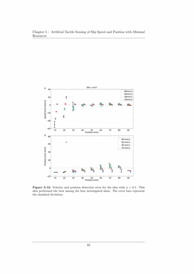
Chapter 5 - Artificial Tactile Sensing of Slip Speed and Position with MinimalResources
10 20 30 40 50 60 70 80 90 −60
−40
−20
0
20
40
Position [mm]
Spe
ed
err
or
[mm
/s]
Skin α=0.1
80mm/s60mm/s40mm/s20mm/s
10 20 30 40 50 60 70 80 90 −20
0
20
40
60
80
Position [mm]
Po
siti
on
err
or
[mm
]
80 mm/s60 mm/s40 mm/s20 mm/s
A
B
Figure 5.12: Velocity and position detection error for the skin with α = 0.1. Thisskin performed the best among the four investigated skins. The error bars representthe standard deviation.
85
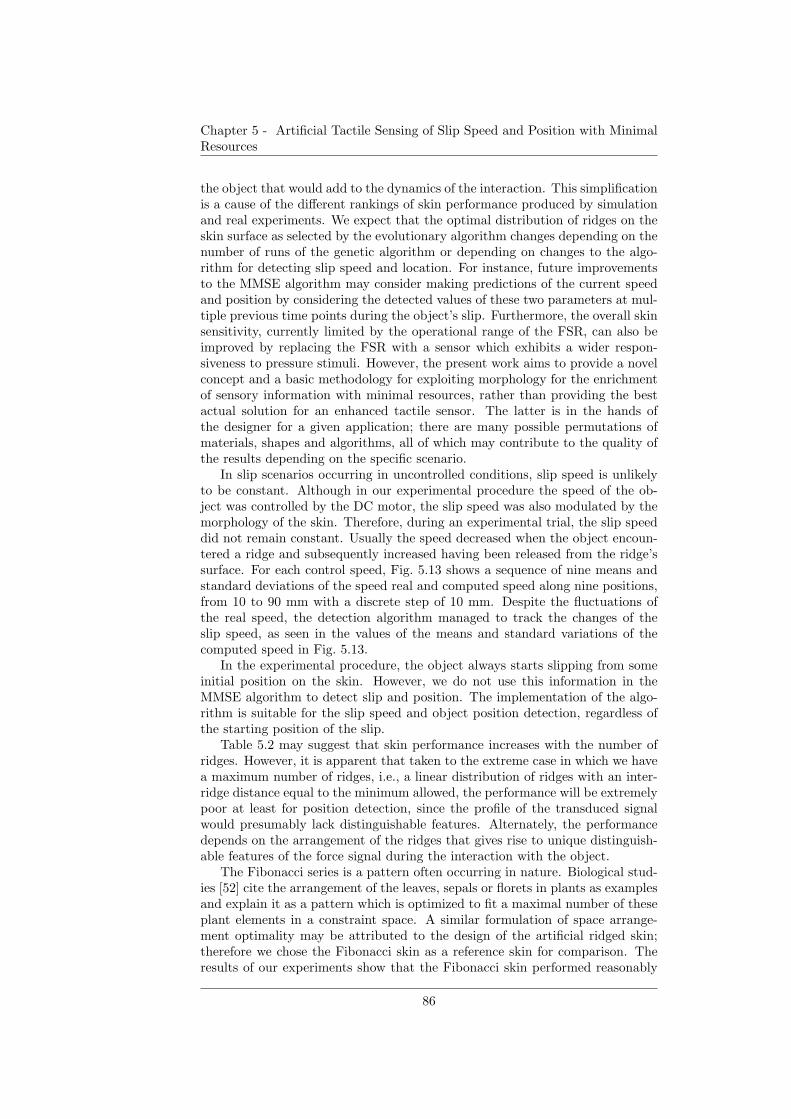
Chapter 5 - Artificial Tactile Sensing of Slip Speed and Position with MinimalResources
the object that would add to the dynamics of the interaction. This simplificationis a cause of the different rankings of skin performance produced by simulationand real experiments. We expect that the optimal distribution of ridges on theskin surface as selected by the evolutionary algorithm changes depending on thenumber of runs of the genetic algorithm or depending on changes to the algo-rithm for detecting slip speed and location. For instance, future improvementsto the MMSE algorithm may consider making predictions of the current speedand position by considering the detected values of these two parameters at mul-tiple previous time points during the object’s slip. Furthermore, the overall skinsensitivity, currently limited by the operational range of the FSR, can also beimproved by replacing the FSR with a sensor which exhibits a wider respon-siveness to pressure stimuli. However, the present work aims to provide a novelconcept and a basic methodology for exploiting morphology for the enrichmentof sensory information with minimal resources, rather than providing the bestactual solution for an enhanced tactile sensor. The latter is in the hands ofthe designer for a given application; there are many possible permutations ofmaterials, shapes and algorithms, all of which may contribute to the quality ofthe results depending on the specific scenario.
In slip scenarios occurring in uncontrolled conditions, slip speed is unlikelyto be constant. Although in our experimental procedure the speed of the ob-ject was controlled by the DC motor, the slip speed was also modulated by themorphology of the skin. Therefore, during an experimental trial, the slip speeddid not remain constant. Usually the speed decreased when the object encoun-tered a ridge and subsequently increased having been released from the ridge’ssurface. For each control speed, Fig. 5.13 shows a sequence of nine means andstandard deviations of the speed real and computed speed along nine positions,from 10 to 90 mm with a discrete step of 10 mm. Despite the fluctuations ofthe real speed, the detection algorithm managed to track the changes of theslip speed, as seen in the values of the means and standard variations of thecomputed speed in Fig. 5.13.
In the experimental procedure, the object always starts slipping from someinitial position on the skin. However, we do not use this information in theMMSE algorithm to detect slip and position. The implementation of the algo-rithm is suitable for the slip speed and object position detection, regardless ofthe starting position of the slip.
Table 5.2 may suggest that skin performance increases with the number ofridges. However, it is apparent that taken to the extreme case in which we havea maximum number of ridges, i.e., a linear distribution of ridges with an inter-ridge distance equal to the minimum allowed, the performance will be extremelypoor at least for position detection, since the profile of the transduced signalwould presumably lack distinguishable features. Alternately, the performancedepends on the arrangement of the ridges that gives rise to unique distinguish-able features of the force signal during the interaction with the object.
The Fibonacci series is a pattern often occurring in nature. Biological stud-ies [52] cite the arrangement of the leaves, sepals or florets in plants as examplesand explain it as a pattern which is optimized to fit a maximal number of theseplant elements in a constraint space. A similar formulation of space arrange-ment optimality may be attributed to the design of the artificial ridged skin;therefore we chose the Fibonacci skin as a reference skin for comparison. Theresults of our experiments show that the Fibonacci skin performed reasonably
86
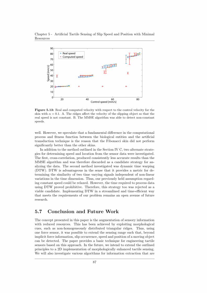
Chapter 5 - Artificial Tactile Sensing of Slip Speed and Position with MinimalResources
20 40 60 800
10
20
30
40
50
60
70
80
90
Control speed [mm/s]
Spe
ed
[mm
/s]
Real speedComputed speed
Figure 5.13: Real and computed velocity with respect to the control velocity for theskin with α = 0.1. A. The ridges affect the velocity of the slipping object so that thereal speed is not constant. B. The MMSE algorithm was able to detect non-constantspeeds.
well. However, we speculate that a fundamental difference in the computationalprocess and fitness function between the biological entities and the artificialtransduction technique is the reason that the Fibonacci skin did not performsignificantly better than the other skins.
In addition to the method outlined in the Section IV C, two alternate strate-gies for determining speed and location from the sensor data were investigated.The first, cross-correlation, produced consistently less accurate results than theMMSE algorithm and was therefore discarded as a candidate strategy for an-alyzing the data. The second method investigated was dynamic time warping(DTW). DTW is advantageous in the sense that it provides a metric for de-termining the similarity of two time varying signals independent of non-linearvariations in the time dimension. Thus, our previously held assumption regard-ing constant speed could be relaxed. However, the time required to process datausing DTW proved prohibitive. Therefore, this strategy too was rejected as aviable candidate. Implementing DTW in a streamlined and time-efficient waythat meets the requirements of our problem remains an open avenue of futureresearch.
5.7 Conclusion and Future Work
The concept presented in this paper is the augmentation of sensory informationwith reduced resources. This has been achieved by exploiting morphologicalcues, such as non-homogeneously distributed triangular ridges. Thus, usingone force sensor, it was possible to extend the sensing range such that, beyondimplicit force information, slip occurrence, speed and position of a moving objectcan be detected. The paper provides a basic technique for engineering tactilesensors based on this approach. In the future, we intend to extend the outlinedprinciples to a 2D implementation of morphologically enhanced tactile sensing.We will also investigate various algorithms for information extraction that are
87

Chapter 5 - Artificial Tactile Sensing of Slip Speed and Position with MinimalResources
biologically inspired in order to gain more insight into designs generated bybiological processes. The combination of morphologically-enhanced skins withdistributed tactile arrays is another promising future strategy for increasing thebandwidth of sensory information.
88
Chap
ter5-Artifi
cialTactile
Sensin
gof
Slip
Speed
andPosition
with
Minim
alResou
rces
α Skin spacings Ridge absolute position Max(A) Max(R) Min(F)
0.1 19, 12, 5, 8, 4, 3, 33 0, 19, 31, 36, 44, 48, 51, 84 0.1667 0.7 0.35390.3 4, 3, 48, 29 0, 4, 7, 55, 84 0.8947 0.4 0.46630.5 5, 12, 67 0, 5, 17, 84 0.9737 0.3 0.36050.7 7, 64, 13 0, 7, 71, 84 0.9737 0.3 0.22110.9 6, 20, 58 0, 6, 26, 84 0.9737 0.3 0.0937
Fibonacci 5, 34, 21, 8, 3, 13 0, 5, 39, 60, 68, 71, 84 0.3789 0.6 −
Table 5.1: Results of GA.
89

Chapter 5 - Artificial Tactile Sensing of Slip Speed and Position with MinimalResources
NRMSDSkin Type V[%] P[%] Avg. [%]α = 0.1 0.21 0.15 0.18
α = 0.3 0.32 0.24 0.28
α = 0.5 0.38 0.20 0.29
Fibonacci 0.26 0.22 0.24
Avg. [%] 0.29 0.20
Table 5.2: Normalized root-mean-square deviation (NRMSD) of speed (V) and po-sition(P).
90
Chapter 6
Design and Evaluation of a
Multi-Modal Haptic Skin
Stimulation ApparatusHaptic information artificiallygenerated by a dynamical 2Dcontact with a skin
Chapter 6 is a preliminary study on the design of a force and slip speed hapticdevice and on the potential information that its stimulation signals could carry.Human grasping and manipulation are facilitated by cutaneous mechanorecep-tors that provide information about contact location, pressure, and events suchas making and breaking contact. A challenge in designing haptic feedback de-vices for the wearer of a prosthetic hand is simultaneous display of multipletypes of haptic information. We present the preliminary design and evaluationof an apparatus for relaying multi-modal haptic information. The apparatusmoves a set of contact points tangentially over the skin at a controlled speed,with controlled normal force. We apply this stimulus to an artificial skin in-strumented with an embedded accelerometer, and characterize the resultingsignals. Vibration frequency increases with applied normal force and tangentialspeed, whereas vibration amplitude increases with normal force and depends onskin properties. The results indicate that different forces and speeds can, un-der some conditions, be discriminated using vibration signals alone. Accurateidentification of speeds is provided by series of vibration events that dependon the spatial distribution of contact points. This study motivates future workto perform human perception studies and create a wearable haptic display forprosthetics based on this concept.
5Parts of the material in this chapter previously appeared in: Dana D. Damian, AlejandroHernandez Arieta and Allison M. Okamura (2011),“ Design and Evaluation of a Multi-ModalHaptic Skin Stimulation Apparatus”, International Conference of the IEEE Engineering inMedicine and Biology Society (EMBC)
91
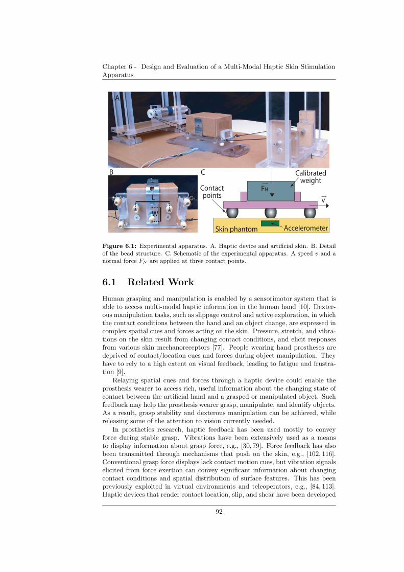
Chapter 6 - Design and Evaluation of a Multi-Modal Haptic Skin StimulationApparatus
A
B
L
W
FN
v
Calibrated weight
Contact points
C
Skin phantom Accelerometer
Figure 6.1: Experimental apparatus. A. Haptic device and artificial skin. B. Detailof the bead structure. C. Schematic of the experimental apparatus. A speed v and anormal force FN are applied at three contact points.
6.1 Related Work
Human grasping and manipulation is enabled by a sensorimotor system that isable to access multi-modal haptic information in the human hand [10]. Dexter-ous manipulation tasks, such as slippage control and active exploration, in whichthe contact conditions between the hand and an object change, are expressed incomplex spatial cues and forces acting on the skin. Pressure, stretch, and vibra-tions on the skin result from changing contact conditions, and elicit responsesfrom various skin mechanoreceptors [77]. People wearing hand prostheses aredeprived of contact/location cues and forces during object manipulation. Theyhave to rely to a high extent on visual feedback, leading to fatigue and frustra-tion [9].
Relaying spatial cues and forces through a haptic device could enable theprosthesis wearer to access rich, useful information about the changing state ofcontact between the artificial hand and a grasped or manipulated object. Suchfeedback may help the prosthesis wearer grasp, manipulate, and identify objects.As a result, grasp stability and dexterous manipulation can be achieved, whilereleasing some of the attention to vision currently needed.
In prosthetics research, haptic feedback has been used mostly to conveyforce during stable grasp. Vibrations have been extensively used as a meansto display information about grasp force, e.g., [30, 79]. Force feedback has alsobeen transmitted through mechanisms that push on the skin, e.g., [102, 116].Conventional grasp force displays lack contact motion cues, but vibration signalselicited from force exertion can convey significant information about changingcontact conditions and spatial distribution of surface features. This has beenpreviously exploited in virtual environments and teleoperators, e.g., [84, 113].Haptic devices that render contact location, slip, and shear have been developed
92
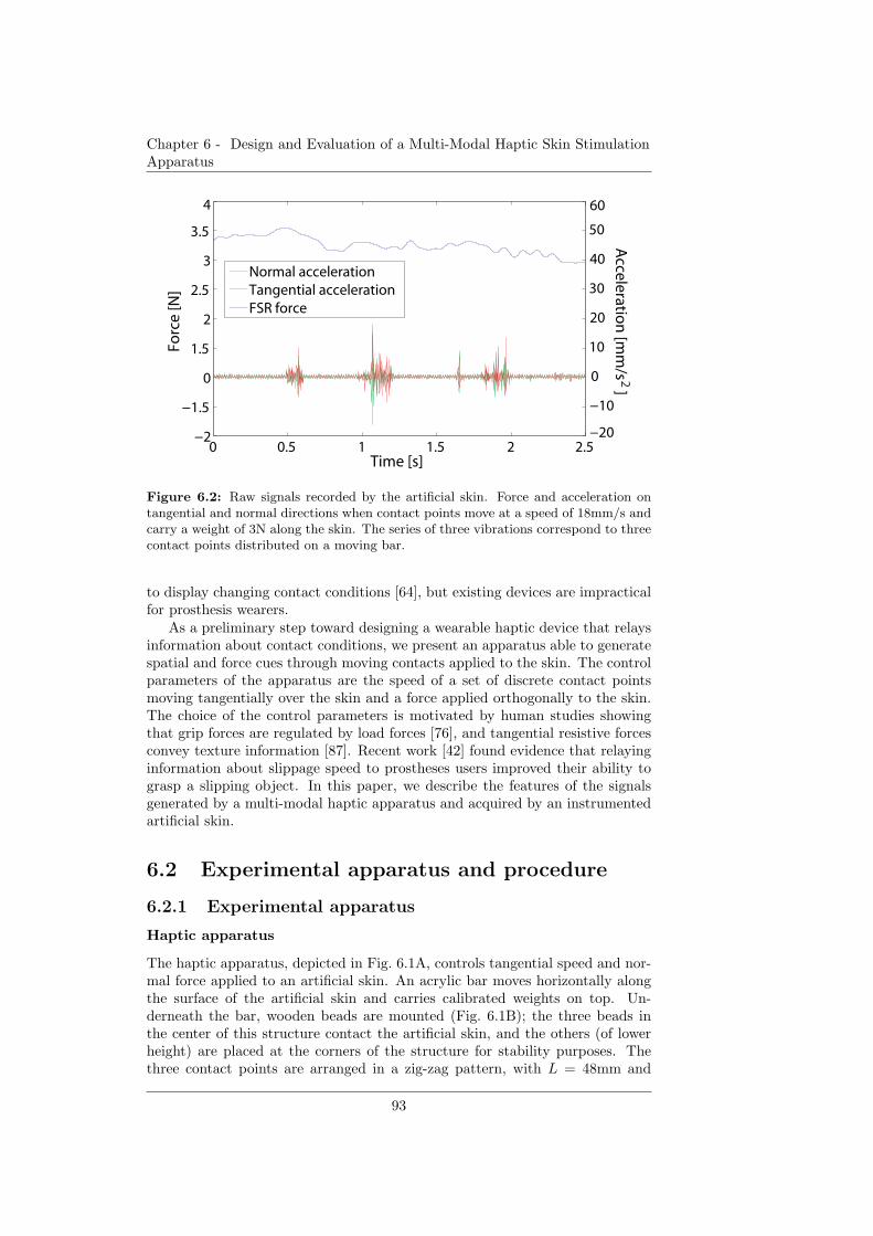
Chapter 6 - Design and Evaluation of a Multi-Modal Haptic Skin StimulationApparatus
0 0.5 1 1.5 2 2.5−2
−1.5
0
1.5
2
2.5
3
3.5
4
Time [s]
Forc
e [N
]
Normal accelerationTangential accelerationFSR force
−20
−10
0
10
20
30
40
50
60
2A
ccele
ration
[mm
/s ]
Figure 6.2: Raw signals recorded by the artificial skin. Force and acceleration ontangential and normal directions when contact points move at a speed of 18mm/s andcarry a weight of 3N along the skin. The series of three vibrations correspond to threecontact points distributed on a moving bar.
to display changing contact conditions [64], but existing devices are impracticalfor prosthesis wearers.
As a preliminary step toward designing a wearable haptic device that relaysinformation about contact conditions, we present an apparatus able to generatespatial and force cues through moving contacts applied to the skin. The controlparameters of the apparatus are the speed of a set of discrete contact pointsmoving tangentially over the skin and a force applied orthogonally to the skin.The choice of the control parameters is motivated by human studies showingthat grip forces are regulated by load forces [76], and tangential resistive forcesconvey texture information [87]. Recent work [42] found evidence that relayinginformation about slippage speed to prostheses users improved their ability tograsp a slipping object. In this paper, we describe the features of the signalsgenerated by a multi-modal haptic apparatus and acquired by an instrumentedartificial skin.
6.2 Experimental apparatus and procedure
6.2.1 Experimental apparatus
Haptic apparatus
The haptic apparatus, depicted in Fig. 6.1A, controls tangential speed and nor-mal force applied to an artificial skin. An acrylic bar moves horizontally alongthe surface of the artificial skin and carries calibrated weights on top. Un-derneath the bar, wooden beads are mounted (Fig. 6.1B); the three beads inthe center of this structure contact the artificial skin, and the others (of lowerheight) are placed at the corners of the structure for stability purposes. Thethree contact points are arranged in a zig-zag pattern, with L = 48mm and
93
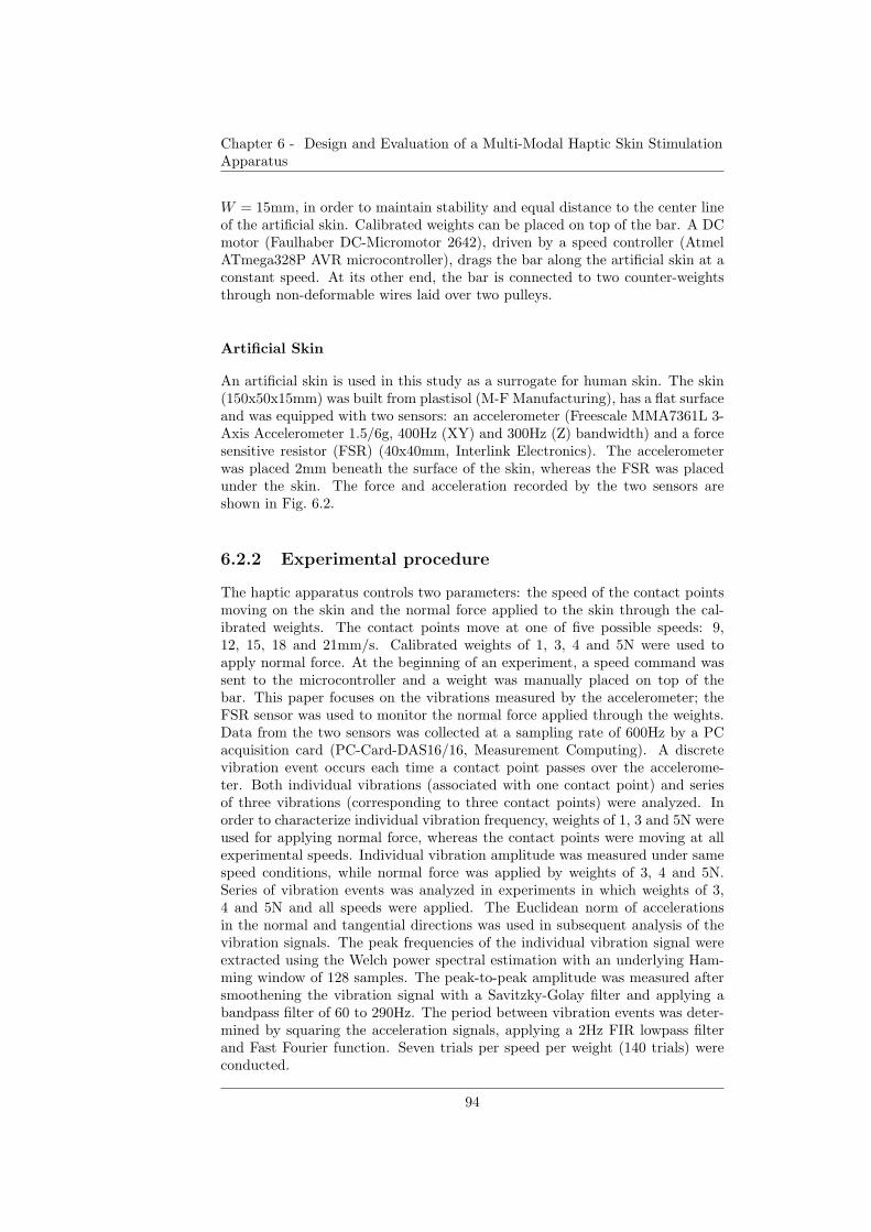
Chapter 6 - Design and Evaluation of a Multi-Modal Haptic Skin StimulationApparatus
W = 15mm, in order to maintain stability and equal distance to the center lineof the artificial skin. Calibrated weights can be placed on top of the bar. A DCmotor (Faulhaber DC-Micromotor 2642), driven by a speed controller (AtmelATmega328P AVR microcontroller), drags the bar along the artificial skin at aconstant speed. At its other end, the bar is connected to two counter-weightsthrough non-deformable wires laid over two pulleys.
Artificial Skin
An artificial skin is used in this study as a surrogate for human skin. The skin(150x50x15mm) was built from plastisol (M-F Manufacturing), has a flat surfaceand was equipped with two sensors: an accelerometer (Freescale MMA7361L 3-Axis Accelerometer 1.5/6g, 400Hz (XY) and 300Hz (Z) bandwidth) and a forcesensitive resistor (FSR) (40x40mm, Interlink Electronics). The accelerometerwas placed 2mm beneath the surface of the skin, whereas the FSR was placedunder the skin. The force and acceleration recorded by the two sensors areshown in Fig. 6.2.
6.2.2 Experimental procedure
The haptic apparatus controls two parameters: the speed of the contact pointsmoving on the skin and the normal force applied to the skin through the cal-ibrated weights. The contact points move at one of five possible speeds: 9,12, 15, 18 and 21mm/s. Calibrated weights of 1, 3, 4 and 5N were used toapply normal force. At the beginning of an experiment, a speed command wassent to the microcontroller and a weight was manually placed on top of thebar. This paper focuses on the vibrations measured by the accelerometer; theFSR sensor was used to monitor the normal force applied through the weights.Data from the two sensors was collected at a sampling rate of 600Hz by a PCacquisition card (PC-Card-DAS16/16, Measurement Computing). A discretevibration event occurs each time a contact point passes over the accelerome-ter. Both individual vibrations (associated with one contact point) and seriesof three vibrations (corresponding to three contact points) were analyzed. Inorder to characterize individual vibration frequency, weights of 1, 3 and 5N wereused for applying normal force, whereas the contact points were moving at allexperimental speeds. Individual vibration amplitude was measured under samespeed conditions, while normal force was applied by weights of 3, 4 and 5N.Series of vibration events was analyzed in experiments in which weights of 3,4 and 5N and all speeds were applied. The Euclidean norm of accelerationsin the normal and tangential directions was used in subsequent analysis of thevibration signals. The peak frequencies of the individual vibration signal wereextracted using the Welch power spectral estimation with an underlying Ham-ming window of 128 samples. The peak-to-peak amplitude was measured aftersmoothening the vibration signal with a Savitzky-Golay filter and applying abandpass filter of 60 to 290Hz. The period between vibration events was deter-mined by squaring the acceleration signals, applying a 2Hz FIR lowpass filterand Fast Fourier function. Seven trials per speed per weight (140 trials) wereconducted.
94
Chapter 6 - Design and Evaluation of a Multi-Modal Haptic Skin StimulationApparatus
9 12 15 18 21100
150
200
250
300
350
400
Speed [mm/s]
Vib
rati
on
fre
qu
en
cy [H
z]
1N3 N5 N
1 3 5100
150
200
250
300
350
400
Normal force [N]
Vib
rati
on
fre
qu
en
cy [H
z]
9 mm/s12 mm/s15 mm/s18 mm/s21 mm/s
A
B
Figure 6.3: Vibration frequency with respect to tangential speed (A) and normalforce (B). The frequency of vibrations increases with both the tangential speed andnormal force.
6.3 Results
Individual vibrations
Vibration frequency was computed for each vibration event in each trial, and isplotted with respect to tangential speed of the contact points (Fig. 6.3A) andnormal force applied to the skin (Fig. 6.3B). The results show that the vibrationfrequency increases monotonically and linearly with the tangential speed andnormal force. For each speed, there was a significant difference in vibrationfrequency for normal forces of 1, 3 and 5N, as shown in Table 6.1A. Singlefactor analysis of variance (ANOVA) with three levels, corresponding to thethree forces, yielded p < 0.01 for each condition shown in Table 6.1A. Tukeypost hoc method indicated that significant differences appear between forces of1 and 5N for each speed. ANOVA revealed a difference in vibration frequencyfor the tangential speeds of 9, 15 and 21mm/s at normal forces of 1, 3 and 5N.Each of the conditions yielded p < 0.01 and are shown in Table 6.1B. Tukeypost hoc method found that significant differences appear between speeds of 9and 21mm/s.
Figure 6.4 shows vibration amplitude with respect to tangential speed andnormal force. The plots reveal trends according to which vibration amplitudelinearly depends on the normal force and has a nonlinear dependence on thetangential speed. A single-factor ANOVA with three levels, corresponding tonormal forces of 3, 4 and 5N, yielded significant differences (p < 0.01) for tan-
95
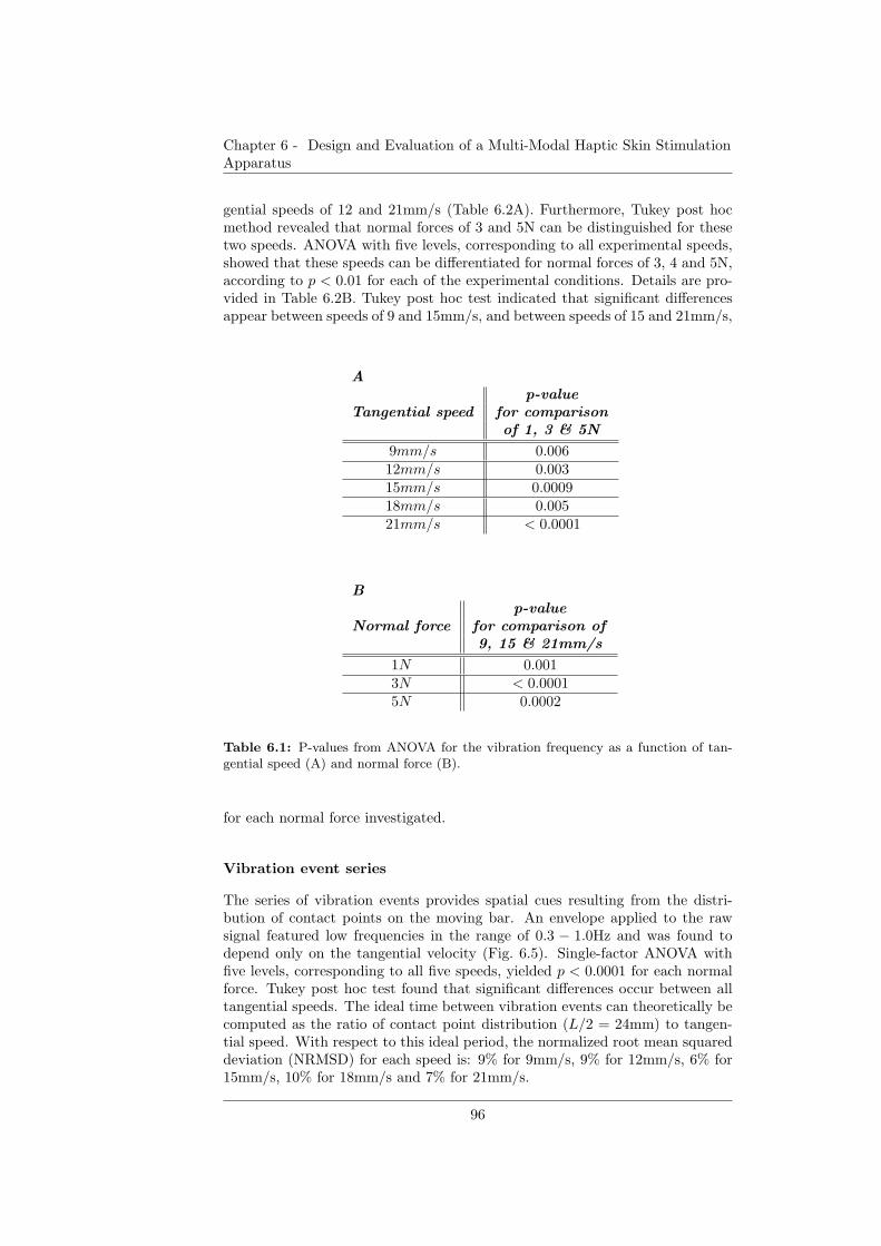
Chapter 6 - Design and Evaluation of a Multi-Modal Haptic Skin StimulationApparatus
gential speeds of 12 and 21mm/s (Table 6.2A). Furthermore, Tukey post hocmethod revealed that normal forces of 3 and 5N can be distinguished for thesetwo speeds. ANOVA with five levels, corresponding to all experimental speeds,showed that these speeds can be differentiated for normal forces of 3, 4 and 5N,according to p < 0.01 for each of the experimental conditions. Details are pro-vided in Table 6.2B. Tukey post hoc test indicated that significant differencesappear between speeds of 9 and 15mm/s, and between speeds of 15 and 21mm/s,
Ap-value
Tangential speed for comparisonof 1, 3 & 5N
9mm/s 0.00612mm/s 0.00315mm/s 0.000918mm/s 0.00521mm/s < 0.0001
Bp-value
Normal force for comparison of9, 15 & 21mm/s
1N 0.0013N < 0.00015N 0.0002
Table 6.1: P-values from ANOVA for the vibration frequency as a function of tan-gential speed (A) and normal force (B).
for each normal force investigated.
Vibration event series
The series of vibration events provides spatial cues resulting from the distri-bution of contact points on the moving bar. An envelope applied to the rawsignal featured low frequencies in the range of 0.3 − 1.0Hz and was found todepend only on the tangential velocity (Fig. 6.5). Single-factor ANOVA withfive levels, corresponding to all five speeds, yielded p < 0.0001 for each normalforce. Tukey post hoc test found that significant differences occur between alltangential speeds. The ideal time between vibration events can theoretically becomputed as the ratio of contact point distribution (L/2 = 24mm) to tangen-tial speed. With respect to this ideal period, the normalized root mean squareddeviation (NRMSD) for each speed is: 9% for 9mm/s, 9% for 12mm/s, 6% for15mm/s, 10% for 18mm/s and 7% for 21mm/s.
96
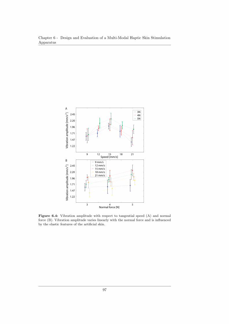
Chapter 6 - Design and Evaluation of a Multi-Modal Haptic Skin StimulationApparatus
3 4 5Normal force [N]
9 mm/s12 mm/s15 mm/s18 mm/s21 mm/s
Vib
rati
on
am
plit
ud
e [m
m/s
]
2
1.22
1.47
1.71
1.96
2.20
2.45
B
9 12 15 18 21
1.22
1.47
1.71
1.96
2.20
2.45
Speed [mm/s]
3N4N5N
Vib
rati
on
am
plit
ud
e [m
m/s
]
2
A
Figure 6.4: Vibration amplitude with respect to tangential speed (A) and normalforce (B). Vibration amplitude varies linearly with the normal force and is influencedby the elastic features of the artificial skin.
97
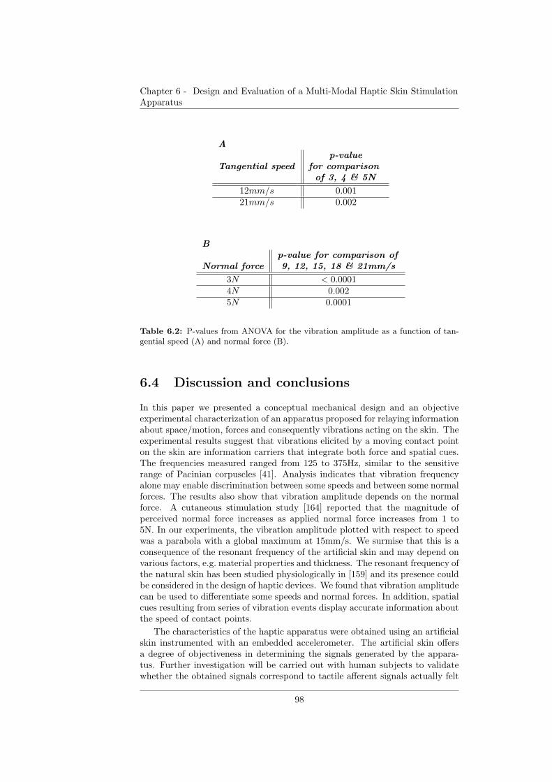
Chapter 6 - Design and Evaluation of a Multi-Modal Haptic Skin StimulationApparatus
Ap-value
Tangential speed for comparisonof 3, 4 & 5N
12mm/s 0.00121mm/s 0.002
Bp-value for comparison of
Normal force 9, 12, 15, 18 & 21mm/s
3N < 0.00014N 0.0025N 0.0001
Table 6.2: P-values from ANOVA for the vibration amplitude as a function of tan-gential speed (A) and normal force (B).
6.4 Discussion and conclusions
In this paper we presented a conceptual mechanical design and an objectiveexperimental characterization of an apparatus proposed for relaying informationabout space/motion, forces and consequently vibrations acting on the skin. Theexperimental results suggest that vibrations elicited by a moving contact pointon the skin are information carriers that integrate both force and spatial cues.The frequencies measured ranged from 125 to 375Hz, similar to the sensitiverange of Pacinian corpuscles [41]. Analysis indicates that vibration frequencyalone may enable discrimination between some speeds and between some normalforces. The results also show that vibration amplitude depends on the normalforce. A cutaneous stimulation study [164] reported that the magnitude ofperceived normal force increases as applied normal force increases from 1 to5N. In our experiments, the vibration amplitude plotted with respect to speedwas a parabola with a global maximum at 15mm/s. We surmise that this is aconsequence of the resonant frequency of the artificial skin and may depend onvarious factors, e.g. material properties and thickness. The resonant frequency ofthe natural skin has been studied physiologically in [159] and its presence couldbe considered in the design of haptic devices. We found that vibration amplitudecan be used to differentiate some speeds and normal forces. In addition, spatialcues resulting from series of vibration events display accurate information aboutthe speed of contact points.
The characteristics of the haptic apparatus were obtained using an artificialskin instrumented with an embedded accelerometer. The artificial skin offersa degree of objectiveness in determining the signals generated by the appara-tus. Further investigation will be carried out with human subjects to validatewhether the obtained signals correspond to tactile afferent signals actually felt
98
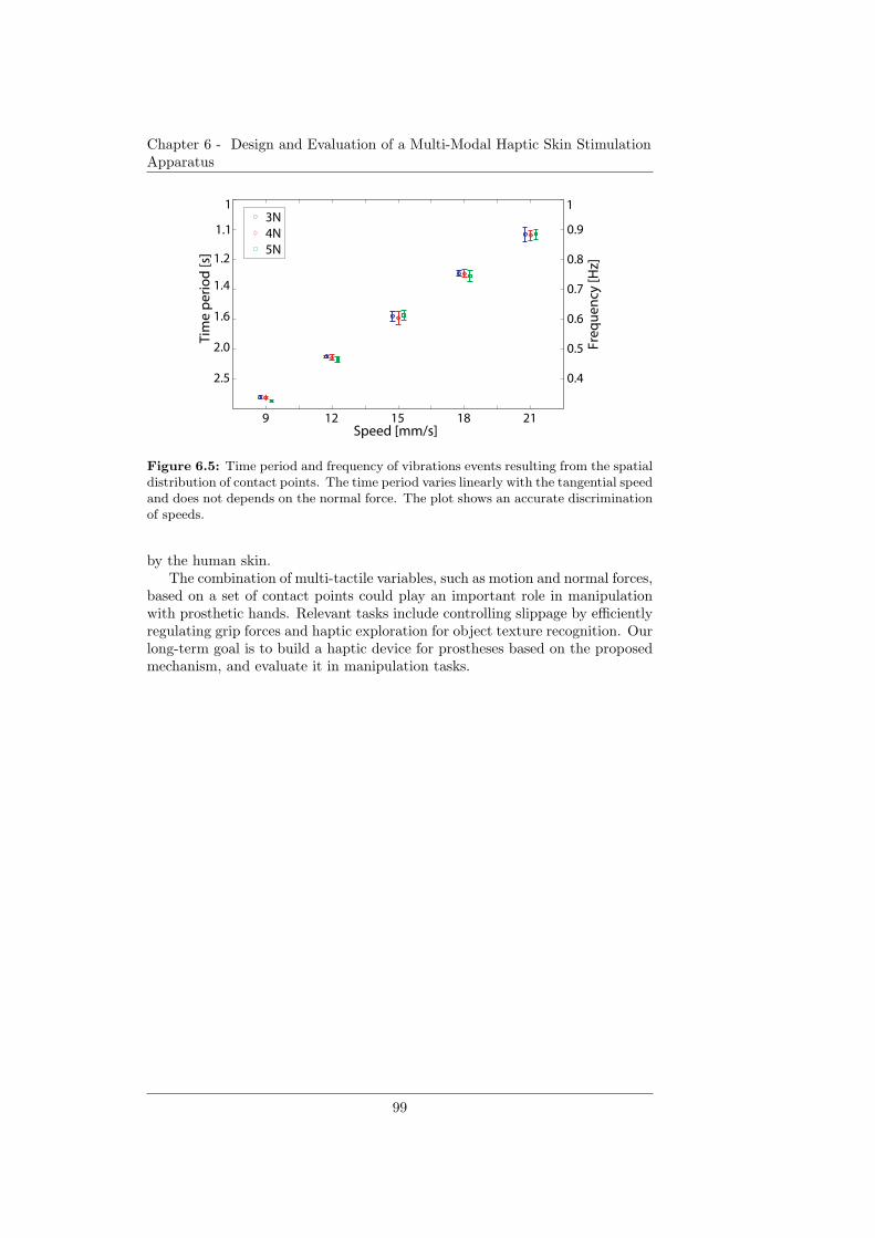
Chapter 6 - Design and Evaluation of a Multi-Modal Haptic Skin StimulationApparatus
9 12 15 18 21Speed [mm/s]
3N4N5N
2.5
2.0
1.6
1.4
1.2
1.1
1Ti
me
pe
rio
d [s
]
0.4
0.5
0.6
0.7
0.8
0.9
1
Fre
qu
en
cy [H
z]
Figure 6.5: Time period and frequency of vibrations events resulting from the spatialdistribution of contact points. The time period varies linearly with the tangential speedand does not depends on the normal force. The plot shows an accurate discriminationof speeds.
by the human skin.The combination of multi-tactile variables, such as motion and normal forces,
based on a set of contact points could play an important role in manipulationwith prosthetic hands. Relevant tasks include controlling slippage by efficientlyregulating grip forces and haptic exploration for object texture recognition. Ourlong-term goal is to build a haptic device for prostheses based on the proposedmechanism, and evaluate it in manipulation tasks.
99

Chapter 6 - Design and Evaluation of a Multi-Modal Haptic Skin StimulationApparatus
100
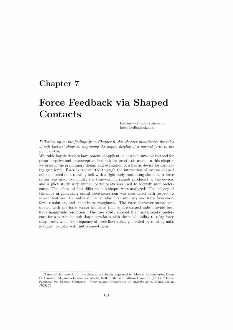
Chapter 7
Force Feedback via Shaped
ContactsInfluence of tactors shape onforce feedback signals
Following up on the findings from Chapter 6, this chapter investigates the rolesof soft tactors’ shape in improving the haptic display of a normal force to thehuman skin.Wearable haptic devices have potential application as a non-invasive method forproprioceptive and exteroceptive feedback for prosthesis users. In this chapterwe present the preliminary design and evaluation of a haptic device for display-ing grip force. Force is transmitted through the interaction of various shapednubs mounted on a rotating belt with a rigid body contacting the skin. A forcesensor was used to quantify the time-varying signals produced by the device,and a pilot study with human participants was used to identify user prefer-ences. The effects of four different nub shapes were analyzed. The efficacy ofthe nubs in generating useful force sensations was considered with respect toseveral features: the nub’s ability to relay force intensity and force frequency,force resolution, and smoothness/roughness. The force characterization con-ducted with the force sensor indicates that square-shaped nubs provide bestforce magnitude resolution. The user study showed that participants’ prefer-ence for a particular nub shape correlates with the nub’s ability to relay forcemagnitude, while the frequency of force fluctuation generated by rotating nubsis tightly coupled with nub’s smoothness.
6Parts of the material in this chapter previously appeared in: Marvin Ludersdorfer, DanaD. Damian, Alejandro Hernandez Arieta, Rolf Pfeifer and Allison Okamura (2011), “ ForceFeedback via Shaped Contacts”, International Conference on Morphological Computation(ICMC)
101
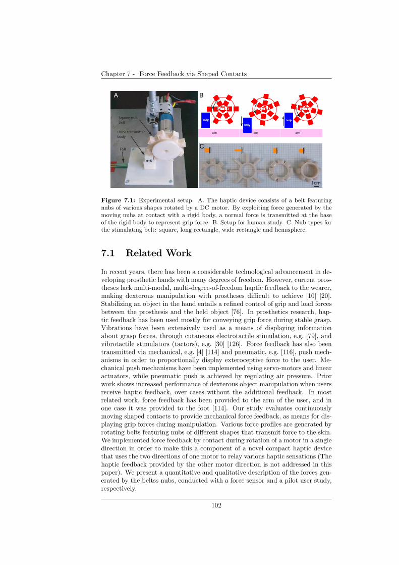
Chapter 7 - Force Feedback via Shaped Contacts
body
force belt
arm
1cm
FSR
Force transmitter
body
Square-nub
beltbody
force belt
arm
body
force belt
arm
A B
C
Figure 7.1: Experimental setup. A. The haptic device consists of a belt featuringnubs of various shapes rotated by a DC motor. By exploiting force generated by themoving nubs at contact with a rigid body, a normal force is transmitted at the baseof the rigid body to represent grip force. B. Setup for human study. C. Nub types forthe stimulating belt: square, long rectangle, wide rectangle and hemisphere.
7.1 Related Work
In recent years, there has been a considerable technological advancement in de-veloping prosthetic hands with many degrees of freedom. However, current pros-theses lack multi-modal, multi-degree-of-freedom haptic feedback to the wearer,making dexterous manipulation with prostheses difficult to achieve [10] [20].Stabilizing an object in the hand entails a refined control of grip and load forcesbetween the prosthesis and the held object [76]. In prosthetics research, hap-tic feedback has been used mostly for conveying grip force during stable grasp.Vibrations have been extensively used as a means of displaying informationabout grasp forces, through cutaneous electrotactile stimulation, e.g. [79], andvibrotactile stimulators (tactors), e.g. [30] [126]. Force feedback has also beentransmitted via mechanical, e.g. [4] [114] and pneumatic, e.g. [116], push mech-anisms in order to proportionally display exteroceptive force to the user. Me-chanical push mechanisms have been implemented using servo-motors and linearactuators, while pneumatic push is achieved by regulating air pressure. Priorwork shows increased performance of dexterous object manipulation when usersreceive haptic feedback, over cases without the additional feedback. In mostrelated work, force feedback has been provided to the arm of the user, and inone case it was provided to the foot [114]. Our study evaluates continuouslymoving shaped contacts to provide mechanical force feedback, as means for dis-playing grip forces during manipulation. Various force profiles are generated byrotating belts featuring nubs of different shapes that transmit force to the skin.We implemented force feedback by contact during rotation of a motor in a singledirection in order to make this a component of a novel compact haptic devicethat uses the two directions of one motor to relay various haptic sensations (Thehaptic feedback provided by the other motor direction is not addressed in thispaper). We present a quantitative and qualitative description of the forces gen-erated by the beltss nubs, conducted with a force sensor and a pilot user study,respectively.
102
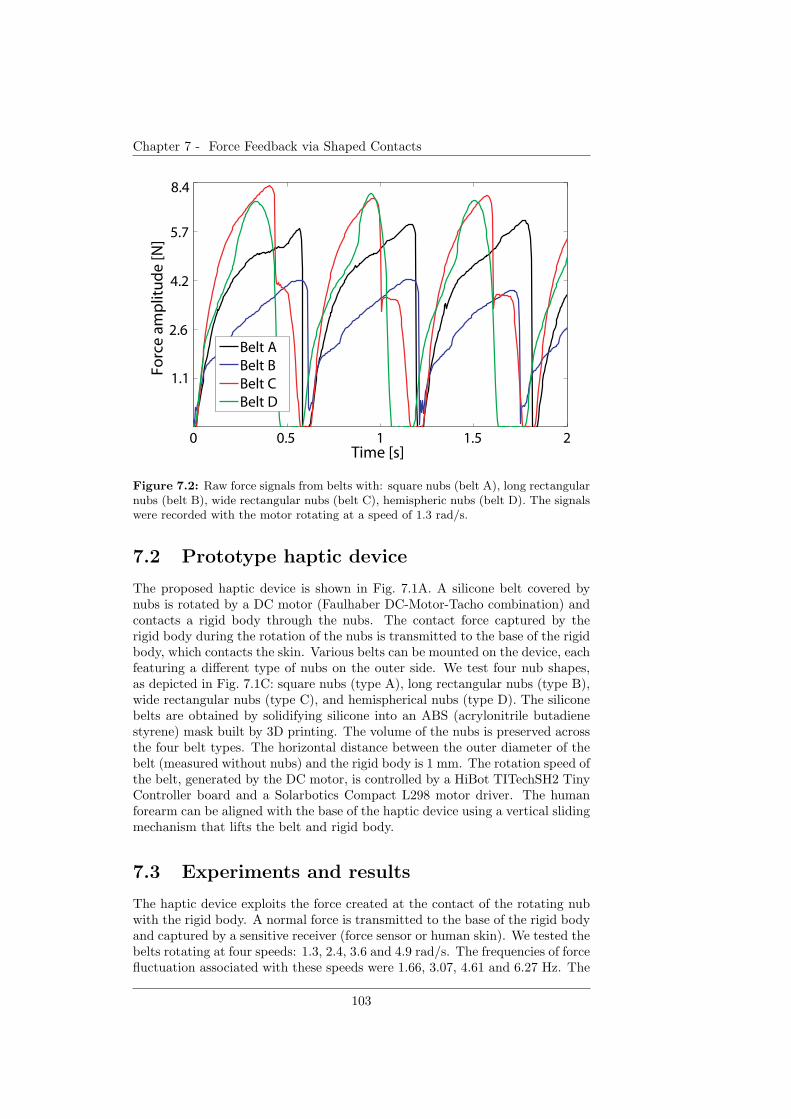
Chapter 7 - Force Feedback via Shaped Contacts
0 0.5 1 1.5 2
1.1
2.6
4.2
5.7
8.4
Time [s]
Forc
e a
mp
litu
de
[N]
Belt ABelt BBelt CBelt D
Figure 7.2: Raw force signals from belts with: square nubs (belt A), long rectangularnubs (belt B), wide rectangular nubs (belt C), hemispheric nubs (belt D). The signalswere recorded with the motor rotating at a speed of 1.3 rad/s.
7.2 Prototype haptic device
The proposed haptic device is shown in Fig. 7.1A. A silicone belt covered bynubs is rotated by a DC motor (Faulhaber DC-Motor-Tacho combination) andcontacts a rigid body through the nubs. The contact force captured by therigid body during the rotation of the nubs is transmitted to the base of the rigidbody, which contacts the skin. Various belts can be mounted on the device, eachfeaturing a different type of nubs on the outer side. We test four nub shapes,as depicted in Fig. 7.1C: square nubs (type A), long rectangular nubs (type B),wide rectangular nubs (type C), and hemispherical nubs (type D). The siliconebelts are obtained by solidifying silicone into an ABS (acrylonitrile butadienestyrene) mask built by 3D printing. The volume of the nubs is preserved acrossthe four belt types. The horizontal distance between the outer diameter of thebelt (measured without nubs) and the rigid body is 1 mm. The rotation speed ofthe belt, generated by the DC motor, is controlled by a HiBot TITechSH2 TinyController board and a Solarbotics Compact L298 motor driver. The humanforearm can be aligned with the base of the haptic device using a vertical slidingmechanism that lifts the belt and rigid body.
7.3 Experiments and results
The haptic device exploits the force created at the contact of the rotating nubwith the rigid body. A normal force is transmitted to the base of the rigid bodyand captured by a sensitive receiver (force sensor or human skin). We tested thebelts rotating at four speeds: 1.3, 2.4, 3.6 and 4.9 rad/s. The frequencies of forcefluctuation associated with these speeds were 1.66, 3.07, 4.61 and 6.27 Hz. The
103
Chapter 7 - Force Feedback via Shaped Contacts
evaluation of the haptic device was conducted with (1) a force sensitive resistor(FSR) and (2) human users whose forearm was in contact with the base of therigid body, as depicted in Fig. 7.1B. Signals from the FSR were acquired by adata acquisition system at a 200 Hz sampling rate. Examples of FSR signalswhen pressed by the four types of belts are illustrated in Fig. 7.2.
Evaluation by force sensor
Forty trials per speed per belt were run, and the average and peak force wascomputed. The results (Fig. 7.3) show that speed of rotation determines forcemagnitude for all four types of belts. Single factor analysis of variance (ANOVA)with four levels corresponding to four speeds showed that normal forces can bedifferentiated by speed. A significant difference in force amplitude was foundbetween all speeds (p < 0.001). However, a linear monotonic relationship be-tween speed of rotation and normal force (average or peak) existed only fortype A and B belts. The peak force showed distinct values for speeds and belttypes as well. Another four-level ANOVA conducted for each belt type yieldedp < 0.001 across all speeds. Force amplitude resolution was computed for beltsof type A, B and D, considering speeds 2.4, 3.6 and 4.9 rad/s. Type A belt has aconsiderable higher force resolution than type B and D belts (p < 0.001), basedon a two-level ANOVA performed over measurements of both average and peakforce.
Evaluation by user study
Three volunteers participated in the evaluation of the haptic device. The stim-ulation area was the ventral side of their forearm, where skin is glabrous. Thedevice was enclosed in a box and the forearm reached it through a hole. Theexperiment had four sessions to test the four belts. During each session, partici-pants were provided with ten occurrences of each experimental speed, presentedin a random order (40 trials in total). The rotation speeds changed after each8 s. The participants wore a noise-cancellation headset while a short soundmarked the beginning of a new trial. The participants were asked to evaluatethe relative force magnitude felt in each trial by a signed numeric value symbol-izing the relative increase or decrease of the force magnitude from the previousto current trial. The users completed a post-experiment questionnaire that pro-vided a qualitative evaluation of the sessions (belts). All users said that theyrather used force frequency than force magnitude to interpret the intensity ofthe relayed force. Moreover, the users were asked to rate each session (belt) withrespect to the following parameters: user ability to discriminate between variousforce magnitudes, force frequencies, and perception of smoothness/roughness ofthe force. The participants also ordered the sessions (belts) according to theirpreference for the overall characteristics of the sensations they received. For allparticipants, type D belt was found to be the least suitable in displaying variousforce magnitudes, whereas type A and B belts were the best (two votes and onevote, respectively). Two of the participants assessed that the set of force fre-quencies across belts were different; one participant evaluated them as identical.Regarding the smoothness/roughness of the relayed force, two participants saidthat the type D belt felt the smoothest. The other participant found a negligibledifference in smoothness/roughness across belts. All three participants disliked
104
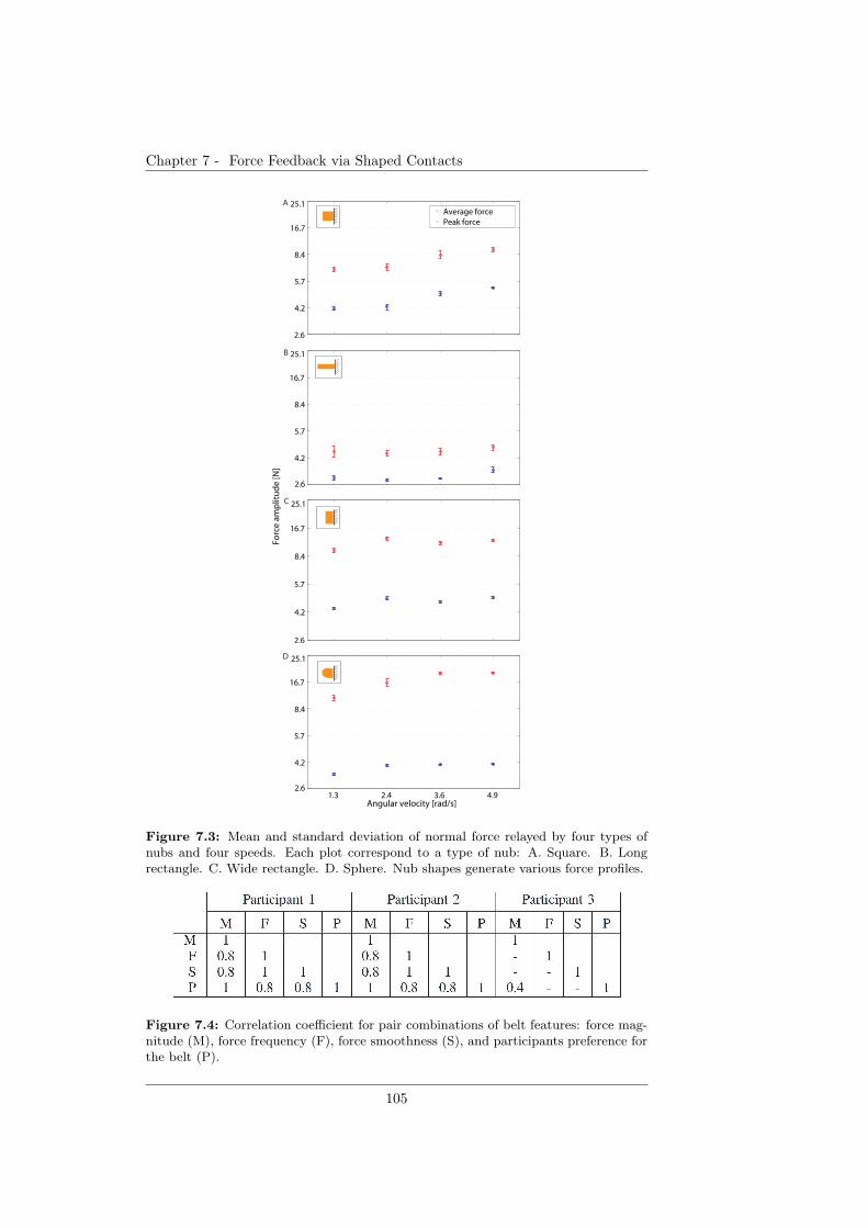
Chapter 7 - Force Feedback via Shaped Contacts
1.3 2.4 3.6 4.92.6
4.2
5.7
8.4
16.7
25.1
Average forcePeak force
1.3 2.4 3.6 4.92.6
4.2
5.7
8.4
16.7
25.1
A
B
1.3 2.4 3.6 4.92.6
4.2
5.7
8.4
16.7
25.1
1.3 2.4 3.6 4.92.6
4.2
5.7
8.4
16.7
25.1
Angular velocity [rad/s]
D
Forc
e a
mp
litu
de
[N]
C
Figure 7.3: Mean and standard deviation of normal force relayed by four types ofnubs and four speeds. Each plot correspond to a type of nub: A. Square. B. Longrectangle. C. Wide rectangle. D. Sphere. Nub shapes generate various force profiles.
Figure 7.4: Correlation coefficient for pair combinations of belt features: force mag-nitude (M), force frequency (F), force smoothness (S), and participants preference forthe belt (P).
105

Chapter 7 - Force Feedback via Shaped Contacts
the sensation the type D belt induced. A correlation coefficient was computedfor the combinations of the belt features investigated in this qualitative study.The results are listed in Table 7.4. There was a correlation between the rat-ing of belts ability to relay various force magnitudes (M) and the order of userpreferences for specific belts (P), as well as between the rating of belts abilityto transmit various force frequencies (F) and the order of belts smoothness (S),which confirms the afore-mentioned observations.
7.4 Discussions and conclusion
The study considers the impact of the shape of a stimulus on force generationand is a preliminary inquiry for an efficient grip force display device. The beltwith square nubs (A) yielded linear monotonic force magnitudes with respectto rotation speed and the highest force magnitude resolution, for both averageand peak force. Compared to this belt, the one with long rectangular nubs (B)reduces both average and peak force. It provides a smoother force transmissiondue to a low average and peak force magnitude and low magnitude resolution.The belts with wide rectangular (C) and hemispherical (D) nubs amplify theforce signal relative to type A belt. Type C belt produces a high duty rate bymaintaining the contact with the rigid body over a relatively longer time. How-ever, force magnitude does not increase significantly as speed increases. Thetype D belt provides more balanced force peaks than the rest of the belts, asseen in Fig. 2. The force increases linearly with the speed, and the increments offorce magnitude are low. The pilot user study shows that force frequency, ratherthan force magnitude, was used as a force evaluation cue. The result indicatesthat frequency had a better tactile display resolution than force magnitude.However, a correlation between the preference for specific belts and their abilityto display various force magnitudes was found. Interestingly, although the setof force frequencies was kept constant for all belts, two participants did not findthem identical. The correlation found between the belt rating with respect tothe users perception of various force frequencies and the belt rating with respectto perception of smoothness potentially indicates a tactile illusion according towhich participants feel different frequencies when a skin contact of constant fre-quency changes its smoothness. In terms of force display by force frequency,there was no general agreement on which belt performs best. The relative highusability of belt A in displaying forces, generally rated by participants, may re-side in the high resolution of force magnitude that this belt exhibits, as resultedfrom the FSR evaluation. We plan to examine belts of type A and B in furtherdevelopment of the haptic device. In particular, we will perform quantitativepsychophysical studies that refine the design of the haptic device and extendthe tactile variables displayed by the haptic device to the manipulated objectsslippage speed.
106
Chapter 8
Wearable Haptic Device for
Cutaneous Force and Slip
Speed DisplayHaptic device for force, slipoccurrence and speed stimulation
Adding up on the studies of Chapter 6 and Chapter 7, this chapter presentsthe design and evaluation of a haptic device that relays quantitative informationabout normal and shear force on the skin with minimal resources.Stable grasp is the result of sensorimotor regulation of forces, ensuring suffi-cient grip force and the integrity of the held object. Grasping with a prosthesisintroduces the challenge of finding the appropriate forces given the engineeredsensorimotor prosthetic interface. Excessive force leads to unnecessary energyuse and possible damage to the object. In contrast, low grip forces lead toslippage. In order for a prosthetic hand to achieve a stable grasp, the hapticinformation provided to the prosthesis wearer needs to display these two an-tagonistic grasp metrics (force and slip) in a quantified way. We present thedesign and evaluation of a wearable single-actuator haptic device that relaysmulti-modal haptic information, such as grip force and slip speed. Two beltsthat are activated in a mutually exclusive manner by the rotation direction ofa single motor exert normal force and tangential motion on the skin surface,respectively. The wearable haptic device is able to display normal forces as atap frequency in the range of approximately 1.5-5.0 Hz and slip speed in therange of 50− 200 mm/s. Within these values, users are able to identify at leastfour stimulation levels for each feedback modality, with short-term training.
7Parts of the material in this chapter previously appeared in: D.D. Damian, M. Ludersdor-fer, Y. Kim, A. Hernandez Arieta, R. Pfeifer and A.M. Okamura (2011), “ Wearable HapticDevice for Cutaneous Force and Slip Feedback”,IEEE International Conference on Roboticsand Automation (ICRA), (in press).
107
Chapter 8 - Wearable Haptic Device for Cutaneous Force and Slip SpeedDisplay
8.1 Related Work
Stability in grasping objects is defined as a load-to-grip-force sensorimotor trans-formation that ensures adequate safety margins against slip. Stable grasp withthe human hand requires both anticipatory parameter control based on a pre-dictive model in the central nervous system (CNS) and discrete-event sensory-driven control [72]. The latter type of control is specifically related to invol-untary slippage scenarios and is based on sensory information to regulate theratio between grip and load forces [10, 63]. With prior knowledge about thegrasped object, proprioceptive cues, and incoming exteroceptive signals, suchas force, pressure, motion and vibration, the CNS is able to integrate sensoryinformation in order to ensure a grip force within safe margins. Prosthetic handsintroduce an engineered sensorimotor interface that hinders the natural relianceon predictive models and is prone to generate significant perturbations in thegrasping process. In such scenarios, stable grasp control becomes a sensorimo-tor transformation highly dependent on incoming sensory information, aimed atregulating the grip force and removing perturbations such as slip and excessiveforce that can damage the held object or involve unnecessary energy use.
At present, haptics research is taking various approaches to feed back sensoryinformation to the user in order to restore grasp stability. The endeavor alsoundertakes the release of the current need of monitoring manipulative actionswith vision, which is a leading factor in user rejection of prostheses (e.g., [9,161])and a serious gap to attaining the integration of a prosthesis as part of thewearer’s body.
Research on sensory substitution has focused on tactile grip force displays.Various works showed that vibrations can be successfully used as a display forgrip force, e.g., [3, 89, 126]. The work of Kaczmarek et al. [79] represents a richreference about the potential of using electrocutaneous or mechanical vibra-tions to excite mechanoreceptors of the human skin and generate various tactilesensations. An alternative approach is a one-to-one physiologically compatiblestimulation, according to which grip force is relayed by means of a push mech-anism onto the skin, e.g, [102,114], or by a cuff around the arm to display grippressure [116].
Although force feedback is relevant for characterizing the applied grip forceof prosthesis wearers, the deprivation of motion cues cannot sufficiently pre-vent or overcome grasp instability. Physiological studies, e.g., [10, 72], showedthat slippage is a pivotal determinant in grip control. Perturbations artificiallygenerated by changing the weight or the slip speed of an object were found toupgrade the agility of the grip response and the ability to overcome slippage,according to early work of Johansson and Cole [72] and recent work of Damianet al. [42], respectively. Nonetheless, slip feedback in prosthetic applicationshas not received much attention. For grasp stability, Tsagarakis et al. [152]developed a device that embeds two miniature motors in a “V” configurationto generate sensations of relative lateral motion at the fingertip. Although thedevice is compact, mountable on the hand finger and supports the display ofvarious motion speeds, its placement would imped the use of the healthy hand ofprostheses users. Slip feedback has been proved successful in tele-manipulationand virtual reality. Edin et al. [14] devised a mechanism in order to transmitfrictional information through solenoids mounted on a held object. The mecha-nism elicited physiological responses that resemble the responses observed with
108

Chapter 8 - Wearable Haptic Device for Cutaneous Force and Slip SpeedDisplay
force tactorcase
force belt
tooth washer
motor shaft
CA slip belt B
1 c
m
D
ratchet
Figure 8.1: The wearable haptic device. A. The wearable haptic device mountedon the forearm. It consists of normal force and slip speed transmission belts. Duringmotor rotation, the nubs on the force belt push onto the force tactor at its base totransmit normal force to the skin. Soft pins mounted on the slip belt contact the skinduring the rotation of the belt. B. Detail of a slip pin made of wood and foam. C.Top view of the wearable haptic device showing the motor shaft on which a toothwasher mechanically enables the rotation of either the force or slip belt depending onthe rotation direction of the motor. D. Front view of the CAD design of the wearablehaptic device. The pulley of the slip belt is omitted to highlight various structurallayers.
occurring slips. Webster et al. [160] developed a two-degree-of-freedom slip dis-play that reproduces the sensations of sliding contact by means of the rotation ofa ball positioned under the user’s fingertip. According to the authors’ findings,slip and force feedback, compared to force feedback alone, offer an improved as-sistance for the manipulation of a virtual object using reduced forces. Recently,the significance of multi-modal sensory substitution in prosthetic applicationshas been credited. Kim et al. [82] developed a multifunctional tactile feedbackdevice that provides feedback on contact, pressure, shear force, vibration, andtemperature. The device was evaluated with users that have undergone targetedreinnervation surgery.
Prompted by physiological findings and practical issues in prosthetics, wepresent a wearable multi-modal haptic device aimed at relaying grip forces andslippage. As such, the device displays normal forces and slip speeds, respectively.We evaluate the properties of the wearable haptic device and user ability toidentify displayed stimuli in quantitative and qualitative studies.
8.2 The proposed wearable haptic device
8.2.1 General design specifications
The wearable haptic device is presented in Fig. 8.1. It consists of two maincomponents: the normal force transmission belt and the slip speed transmissionbelt. The belts are made of silicone by solidifying the elastomer into an ABS(Acrylonitrile Butadiene Styrene) mask built by rapid prototyping. The twobelts are activated in a mutually exclusive manner based on the assumptionthat if an object slips it means there is insufficient grip force, whereas if anobject is tightly grasped, there is no occurring slip. Hence, we opted to usethe rotation direction of a single DC motor (Faulhaber 1727U 012C, regulatedby a HiBot TITechSH2 Tiny Controller board and a Solarbotics Compact L298motor driver) in order to control either the force feedback belt or the slip speedfeedback belt. The selection mechanism of the active feedback belt was achievedby means of a tooth washer mounted on the DC motor’s shaft. On each side
109
Chapter 8 - Wearable Haptic Device for Cutaneous Force and Slip SpeedDisplay
of the tooth washer there is a pulley supporting a feedback belt, loosely placedon the motor shaft and pushed toward the tooth washer by a spring. Theconfiguration of the washer’s teeth constrains one pulley to rotate with themotor, while the other pulley is held fixed by a ratchet mechanism. The wearablehaptic device is designed to be worn on the ventral part of the forearm. Weexploit this flat area of the forearm in order to maintain the belts of the hapticdevice undeformed. The size of the wearable haptic device was determined froma forearm measurement pilot study conducted with 20 humans (4 females and16 males). Based on the study and physical constraints of the components, thesize of the wearable haptic device was set to 56 mm width and 127 mm length.Consequently, the haptic device weighted 209 grams.
8.2.2 Normal force transmission belt
Force belt design
The normal force transmission belt has an inner diameter of 15 mm and outerdiameter of 22 mm. Six square nubs with sides of 7 mm cover the surface ofthe belt. The shape of the nubs was selected based on a previous study [93] inwhich the same force display mechanism was used. During the rotation of thebelt, the nubs periodically push down a rigid body placed in a case at the baseof the force belt. The size of the rigid body is 7 × 9 × 16 mm. The contactforce captured by the rigid body from the belt’s nubs is transmitted to its basewhich in turn makes contact with the skin (see Fig. 8.2). We hereafter refer tothe rigid body as the force tactor. The mechanism enforces the transmissionof a normal force on a skin surface of 63 mm2. Due to the elastic material ofthe nubs, the amplitude of the normal force varies with the speed of the motorrotation by exploiting the principle of momentum. This property was shownin [93] for force tactors pushing on a rigid surface. Similarly, the frequency ofthe normal force can be regulated by the rotation speed of the motor due to theuniform distribution of the nubs on the belt surface.
Force belt performance
Following up on the study in [93], we conducted experiments with the wearablehaptic device in order to characterize the normal force stimulation to the humanskin surface. The wearable device was mounted on the ventral side of the forearmof a single user, while the forearm was resting on a table with the ventralside facing up. A force sensitive resistor (FSR) was placed between the forcetactor and the human skin. Three force recording sessions were conducted at asampling rate of 200 Hz, each of them for 11 motor speeds (33 trials in total).Across the three sessions, the position of the force tactor with respect to theventral side of the forearm was slightly changed. The average and standarddeviation of the normal force amplitude and frequency were computed overfive time segments of a trial. One time segment spanned over three seconds.In Fig. 8.3A the normal force amplitude is plotted with respect to 11 motorspeeds. Although in the previous study [93] the force amplitude showed a lineardependence on the motor speed for a force tactor contacting a rigid surface, themeasurements in the three sessions showed that this linear relation is no longervalid if the stimulation is transmitted to the human skin. From our experimental
110
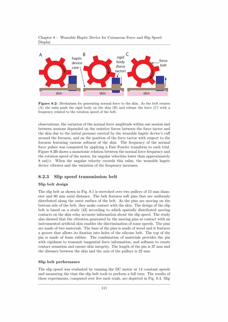
Chapter 8 - Wearable Haptic Device for Cutaneous Force and Slip SpeedDisplay
skinskin
rigid
body
(force
tactor)
force
belt
skin
A B Chaptic
device
case
Figure 8.2: Mechanism for generating normal force to the skin. As the belt rotates(A) the nubs push the rigid body on the skin (B) and release the force (C) with afrequency related to the rotation speed of the belt.
observations, the variation of the normal force amplitude within one session andbetween sessions depended on the resistive forces between the force tactor andthe skin due to the initial pressure exerted by the wearable haptic device’s cuffaround the forearm, and on the position of the force tactor with respect to theforearm featuring various softness of the skin. The frequency of the normalforce pulses was computed by applying a Fast Fourier transform to each trial.Figure 8.3B shows a monotonic relation between the normal force frequency andthe rotation speed of the motor, for angular velocities lower than approximately8 rad/s. When the angular velocity exceeds this value, the wearable hapticdevice vibrates and the variation of the frequency increases.
8.2.3 Slip speed transmission belt
Slip belt design
The slip belt as shown in Fig. 8.1 is stretched over two pulleys of 15 mm diam-eter and 80 mm axial distance. The belt features soft pins that are uniformlydistributed along the outer surface of the belt. As the pins are moving on thebottom side of the belt, they make contact with the skin. The design of the slipbelt is based on a study [43] according to which spatially distributed movingcontacts on the skin relay accurate information about the slip speed. The studyalso showed that the vibration generated by the moving pins at contact with aninstrumented artificial skin enables the discrimination of some speeds. The pinsare made of two materials. The base of the pins is made of wood and it featuresa groove that allows its fixation into holes of the silicone belt. The top of thepin is made of foam rubber. The combination of materials provides the pinwith rigidness to transmit tangential force information, and softness to createcontact sensation and ensure skin integrity. The length of the pin is 37 mm andthe distance between the skin and the axis of the pulleys is 22 mm.
Slip belt performance
The slip speed was evaluated by running the DC motor at 14 constant speedsand measuring the time the slip belt took to perform a full turn. The results ofthese experiments, computed over five such trials, are depicted in Fig. 8.4. Slip
111
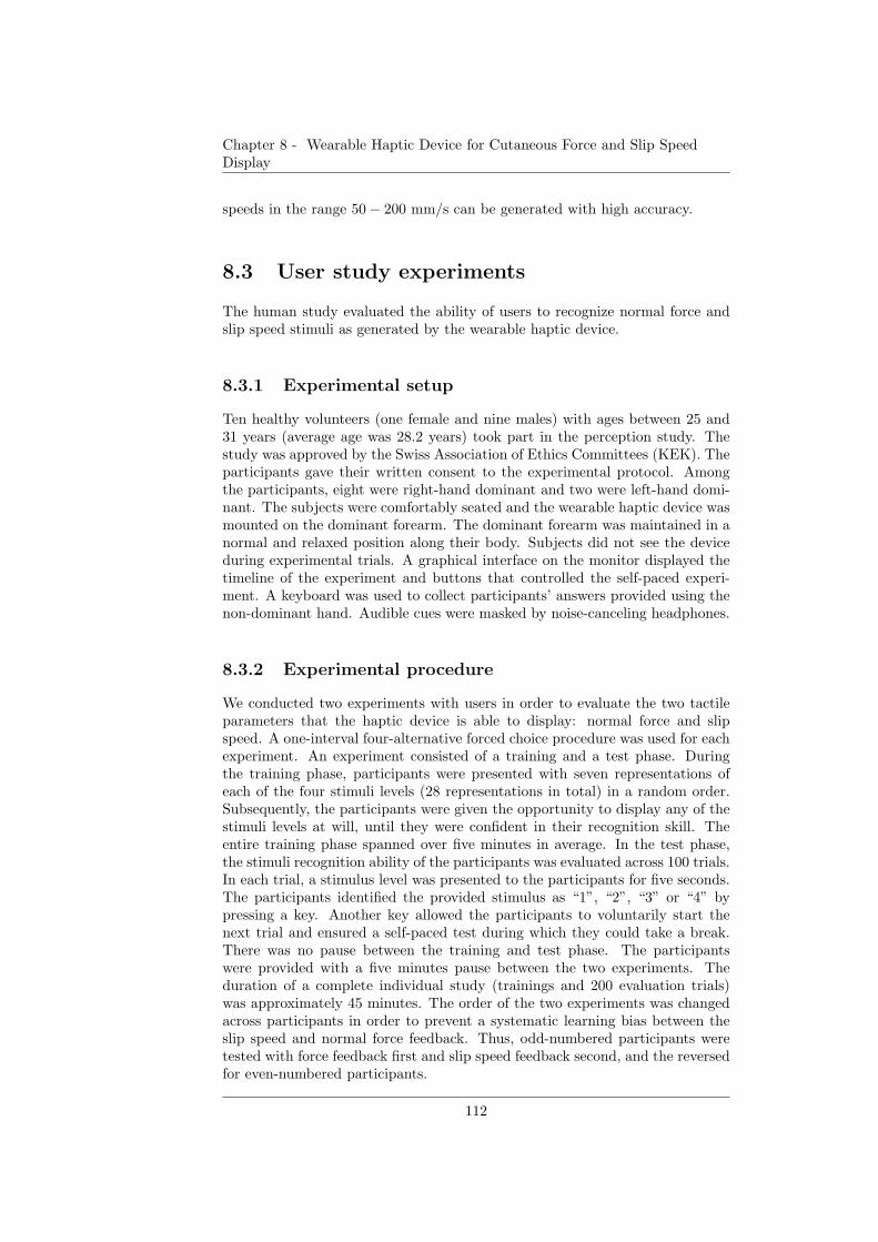
Chapter 8 - Wearable Haptic Device for Cutaneous Force and Slip SpeedDisplay
speeds in the range 50− 200 mm/s can be generated with high accuracy.
8.3 User study experiments
The human study evaluated the ability of users to recognize normal force andslip speed stimuli as generated by the wearable haptic device.
8.3.1 Experimental setup
Ten healthy volunteers (one female and nine males) with ages between 25 and31 years (average age was 28.2 years) took part in the perception study. Thestudy was approved by the Swiss Association of Ethics Committees (KEK). Theparticipants gave their written consent to the experimental protocol. Amongthe participants, eight were right-hand dominant and two were left-hand domi-nant. The subjects were comfortably seated and the wearable haptic device wasmounted on the dominant forearm. The dominant forearm was maintained in anormal and relaxed position along their body. Subjects did not see the deviceduring experimental trials. A graphical interface on the monitor displayed thetimeline of the experiment and buttons that controlled the self-paced experi-ment. A keyboard was used to collect participants’ answers provided using thenon-dominant hand. Audible cues were masked by noise-canceling headphones.
8.3.2 Experimental procedure
We conducted two experiments with users in order to evaluate the two tactileparameters that the haptic device is able to display: normal force and slipspeed. A one-interval four-alternative forced choice procedure was used for eachexperiment. An experiment consisted of a training and a test phase. Duringthe training phase, participants were presented with seven representations ofeach of the four stimuli levels (28 representations in total) in a random order.Subsequently, the participants were given the opportunity to display any of thestimuli levels at will, until they were confident in their recognition skill. Theentire training phase spanned over five minutes in average. In the test phase,the stimuli recognition ability of the participants was evaluated across 100 trials.In each trial, a stimulus level was presented to the participants for five seconds.The participants identified the provided stimulus as “1”, “2”, “3” or “4” bypressing a key. Another key allowed the participants to voluntarily start thenext trial and ensured a self-paced test during which they could take a break.There was no pause between the training and test phase. The participantswere provided with a five minutes pause between the two experiments. Theduration of a complete individual study (trainings and 200 evaluation trials)was approximately 45 minutes. The order of the two experiments was changedacross participants in order to prevent a systematic learning bias between theslip speed and normal force feedback. Thus, odd-numbered participants weretested with force feedback first and slip speed feedback second, and the reversedfor even-numbered participants.
112
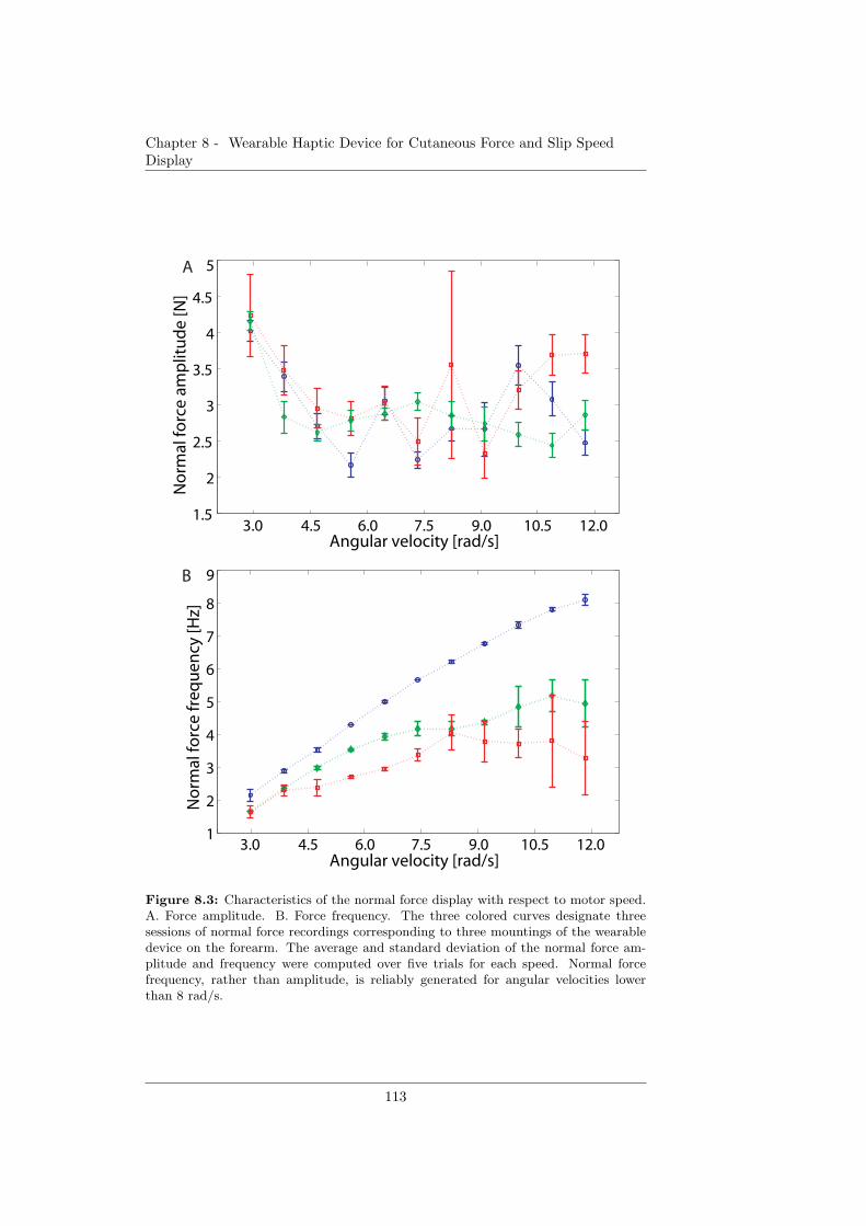
Chapter 8 - Wearable Haptic Device for Cutaneous Force and Slip SpeedDisplay
1
2
3
4
5
6
7
8
9
Angular velocity [rad/s]
No
rmal
fo
rce
fre
qu
en
cy [H
z]
1.5
2
2.5
3
3.5
4
4.5
5
No
rmal
fo
rce
am
plit
ud
e [N
]
Angular velocity [rad/s]
B
A
3.0 4.5 6.0 9.0 10.5 12.07.5
3.0 4.5 6.0 9.0 10.5 12.07.5
Figure 8.3: Characteristics of the normal force display with respect to motor speed.A. Force amplitude. B. Force frequency. The three colored curves designate threesessions of normal force recordings corresponding to three mountings of the wearabledevice on the forearm. The average and standard deviation of the normal force am-plitude and frequency were computed over five trials for each speed. Normal forcefrequency, rather than amplitude, is reliably generated for angular velocities lowerthan 8 rad/s.
113
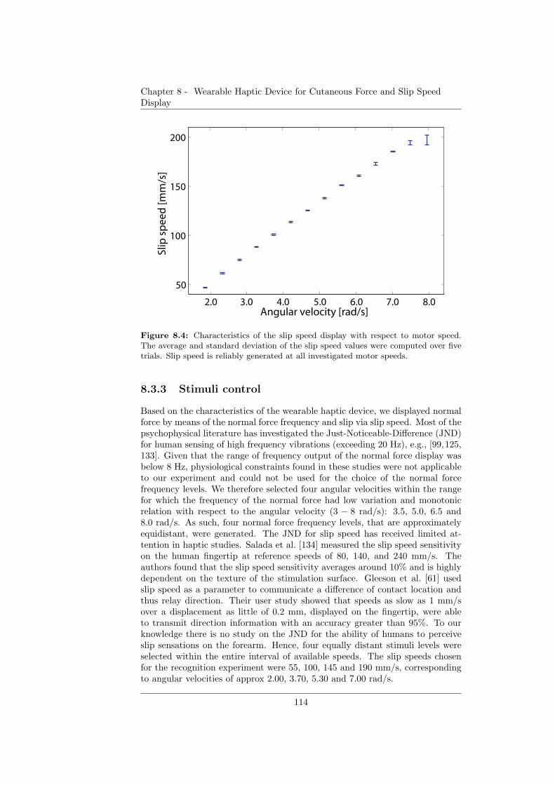
Chapter 8 - Wearable Haptic Device for Cutaneous Force and Slip SpeedDisplay
50
100
150
200
Slip
sp
ee
d [m
m/s
]
4.0 6.0 7.0Angular velocity [rad/s]
2.0 3.0 5.0 8.0
Figure 8.4: Characteristics of the slip speed display with respect to motor speed.The average and standard deviation of the slip speed values were computed over fivetrials. Slip speed is reliably generated at all investigated motor speeds.
8.3.3 Stimuli control
Based on the characteristics of the wearable haptic device, we displayed normalforce by means of the normal force frequency and slip via slip speed. Most of thepsychophysical literature has investigated the Just-Noticeable-Difference (JND)for human sensing of high frequency vibrations (exceeding 20 Hz), e.g., [99,125,133]. Given that the range of frequency output of the normal force display wasbelow 8 Hz, physiological constraints found in these studies were not applicableto our experiment and could not be used for the choice of the normal forcefrequency levels. We therefore selected four angular velocities within the rangefor which the frequency of the normal force had low variation and monotonicrelation with respect to the angular velocity (3 − 8 rad/s): 3.5, 5.0, 6.5 and8.0 rad/s. As such, four normal force frequency levels, that are approximatelyequidistant, were generated. The JND for slip speed has received limited at-tention in haptic studies. Salada et al. [134] measured the slip speed sensitivityon the human fingertip at reference speeds of 80, 140, and 240 mm/s. Theauthors found that the slip speed sensitivity averages around 10% and is highlydependent on the texture of the stimulation surface. Gleeson et al. [61] usedslip speed as a parameter to communicate a difference of contact location andthus relay direction. Their user study showed that speeds as slow as 1 mm/sover a displacement as little of 0.2 mm, displayed on the fingertip, were ableto transmit direction information with an accuracy greater than 95%. To ourknowledge there is no study on the JND for the ability of humans to perceiveslip sensations on the forearm. Hence, four equally distant stimuli levels wereselected within the entire interval of available speeds. The slip speeds chosenfor the recognition experiment were 55, 100, 145 and 190 mm/s, correspondingto angular velocities of approx 2.00, 3.70, 5.30 and 7.00 rad/s.
114
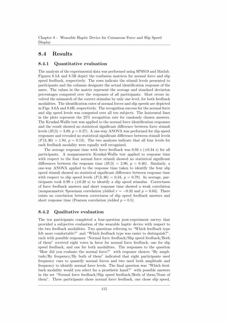
Chapter 8 - Wearable Haptic Device for Cutaneous Force and Slip SpeedDisplay
8.4 Results
8.4.1 Quantitative evaluation
The analysis of the experimental data was performed using SPSS19 and Matlab.Figures 8.5A and 8.5B depict the confusion matrices for normal force and slipspeed feedback, respectively. The rows indicate the stimuli levels presented toparticipants and the columns designate the actual identification response of theusers. The values in the matrix represent the average and standard deviationpercentages computed over the responses of all participants. Most errors in-volved the mismatch of the correct stimulus by only one level, for both feedbackmodalities. The identification rates of normal forces and slip speeds are depictedin Figs. 8.6A and 8.6B, respectively. The recognition success for the normal forceand slip speed levels was computed over all ten subjects. The horizontal linesin the plots represent the 25% recognition rate for randomly chosen answers.The Kruskal-Wallis test was applied to the normal force identification responsesand the result showed no statistical significant difference between force stimulilevels (H(3) = 3.89, p = 0.27). A one-way ANOVA was performed for slip speedresponses and revealed no statistical significant difference between stimuli levels(F (3, 36) = 1.94, p = 0.13). The two analyses indicate that all four levels foreach feedback modality were equally well recognized.
The average response time with force feedback was 0.92 s (±0.34 s) for allparticipants. A nonparametric Kruskal-Wallis test applied to response timewith respect to the four normal force stimuli showed no statistical significantdifferences between the response time (H(3) = 2.90, p = 0.40). Similarly, aone-way ANOVA applied to the response time taken to identify the four slipspeed stimuli showed no statistical significant difference between response timewith respect to slip speed levels (F (3, 36) = 0.34, p = 0.79). In average, par-ticipants took 0.99 s (±0.28 s) to identify a slip speed stimulus. Correctnessof force feedback answers and short response time showed a weak correlation(nonparametric Spearman correlation yielded r = −0.32 and p = 0.04). Thereexists no correlation between correctness of slip speed feedback answers andshort response time (Pearson correlation yielded p = 0.5).
8.4.2 Qualitative evaluation
The ten participants completed a four-question post-experiment survey thatprovided a subjective evaluation of the wearable haptic device with respect tothe two feedback modalities. Two questions referring to “Which feedback typefelt more comfortable?” and “Which feedback type was easier to distinguish?”,each with possible responses “Normal force feedback/Slip speed feedback/Bothof them” received eight votes in favor for normal force feedback, one for slipspeed feedback, and one for both modalities. The responses to the question“How did you evaluate the normal force?” with response choices “By ampli-tude/By frequency/By both of them” indicated that eight participants usedfrequency cues to quantify normal forces and two used both amplitude andfrequency to identify normal force levels. The final question was “Which feed-back modality would you select for a prosthetic hand?” with possible answersin the set “Normal force feedback/Slip speed feedback/Both of them/None ofthem”. Three participants chose normal force feedback, one chose slip speed,
115
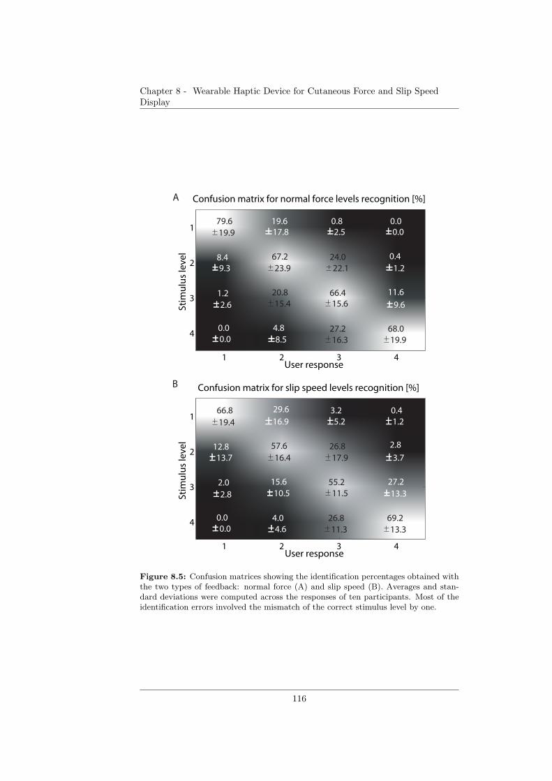
Chapter 8 - Wearable Haptic Device for Cutaneous Force and Slip SpeedDisplay
Confusion matrix for normal force levels recognition [%]
User response
Stim
ulu
s le
vel
1 2 3 4
1
2
3
4
79.6 19.6 0.8 0.0
8.4
1.2
0.0
67.2
20.8
4.8
24.0
66.4
27.2
0.4
11.6
68.0
19.9 17.8 2.5 0.0
9.3 23.9 22.1 1.2
2.6 15.4 15.6 9.6
0.0 8.5 16.3 19.9
Confusion matrix for slip speed levels recognition [%]
User response
Stim
ulu
s le
vel
1 2 3 4
1
2
3
4
66.8 29.6 3.2 0.4
12.8
2.0
0.0
57.6
15.6
4.0
26.8
55.2
26.8
2.8
27.2
69.2
19.4 16.9 5.2 1.2
13.7 16.4 17.9 3.7
2.8 11.5 13.3
0.0 4.6 11.3 13.3
10.5
A
B
Figure 8.5: Confusion matrices showing the identification percentages obtained withthe two types of feedback: normal force (A) and slip speed (B). Averages and stan-dard deviations were computed across the responses of ten participants. Most of theidentification errors involved the mismatch of the correct stimulus level by one.
116
Chapter 8 - Wearable Haptic Device for Cutaneous Force and Slip SpeedDisplay
1 2 3 40
20
40
60
80
100
Succ
ess
rat
e [%
]
Normal force stimuli level
Absolute normal force level recognition
1 2 3 40
20
40
60
80
100
Succ
ess
rat
e [%
]
Slip speed stimuli level
Absolute slip speed level recognition
A
B
Figure 8.6: Absolute stimuli identification rate for the two feedback modalities:normal force (A) and slip speed (B). Averages and standard deviations were computedacross the responses of ten participants. The horizontal lines represent the success ratesfor hypothetically random user responses.
117
Chapter 8 - Wearable Haptic Device for Cutaneous Force and Slip SpeedDisplay
five selected both force and slip speed feedback modalities, and one chose none.
8.5 Discussion
The ability of haptic devices to transmit normal forces and slip speeds holdspromise in enabling grasp stability in prosthetic applications. The current studyis an endeavor to design and evaluate such a haptic device. The characterizationof the haptic device indicated that normal force frequency, rather than ampli-tude, can reliably encode grip force. Similarly, in the qualitative user study,normal force frequency rather than amplitude was used as a force evaluationcue. In manipulation tasks, grip force and slippage may quantitatively be rep-resented by normal force frequency and slip speed, respectively, as generatedby the haptic device. The underlying mechanisms for the two feedback modal-ities grant distinction in the tactile sensation, and consequently in the relayedinformation.
The qualitative results of the user study indicated that participants ratedthe normal force feedback better than the slip speed feedback in terms of dis-play potential. This rating was in agreement with the results of the stimuliidentification test. However, a rigorous ranking of the two feedback modalitiesis not possible without a common comparison unit, e.g. the JND of the displaymodalities. Previous studies [134] show that the sensitivity to slip speed highlydepends on the surface texture. Therefore, the rates of the slip speeds identi-fication could arguably be improved if the soft pins of the slip belt featured asurface texture. A longer training period could also enhance the user abilityto identify stimuli levels for both feedback modalities. As confusion matricesindicated, although users were not perfectly accurate in identifying the stimulilevels, they were able to thoroughly estimate them with one stimulus level de-viation. In manipulation tasks, users do not need to identify absolute valuesof stimuli, but relative values. The study suggests that one method to encodequantitative changes of either normal force or slip speed stimuli is to presentpairs of stimuli between which there is a two-level or three-level difference (e.g.,normal force level 1 followed by normal force level 3, slip speed level 4 followedby slip speed level 1). For these types of stimuli pairs, the identification ratewas in average above 95% for both feedback modalities. Although currentlyforce and slip are displayed in a mutually exclusive way, the functionality of thehaptic device could potentially be advanced to multiplexing the force and slipstimulations for a simultaneous display of the two tactile sensations.
8.6 Conclusions and future work
We proposed the design of a wearable haptic device that displays normal forcesand slip speeds. The haptic device generates normal force frequencies in therange of approximately 1.5− 5.0 Hz and slip speeds of 50− 200 mm/s. Amongthese values, at least four stimuli levels for each feedback modality can be identi-fied by human users. Therefore, normal force frequency and slip speed are possi-ble means to substitute qualitatively and quantitatively grip force and slippage,respectively, in order to endorse stable grasp in prosthetic applications. As asubsequent step, we will conduct experiments in order to assess the JND values
118

Chapter 8 - Wearable Haptic Device for Cutaneous Force and Slip SpeedDisplay
for the normal force frequency and the slip speed on the forearm. Furthermore,we plan to evaluate the wearable haptic device in manipulation tasks in whichthe two types of feedback need to be combined in order to ensure a stable grasp.
119

Chapter 8 - Wearable Haptic Device for Cutaneous Force and Slip SpeedDisplay
120
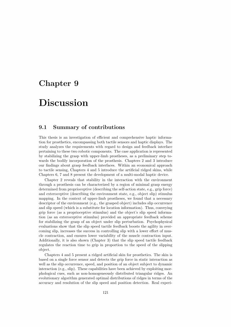
Chapter 9
Discussion
9.1 Summary of contributions
This thesis is an investigation of efficient and comprehensive haptic informa-tion for prosthetics, encompassing both tactile sensors and haptic displays. Thestudy analyzes the requirements with regard to design and feedback interfacepertaining to these two robotic components. The case application is representedby stabilizing the grasp with upper-limb prostheses, as a preliminary step to-wards the bodily incorporation of the prosthesis. Chapters 2 and 3 introduceour findings about grasp feedback interfaces. Within an economical approachto tactile sensing, Chapters 4 and 5 introduce the artificial ridged skins, whileChapters 6, 7 and 8 present the development of a multi-modal haptic device.
Chapter 2 reveals that stability in the interaction with the environmentthrough a prosthesis can be characterized by a region of minimal grasp energydetermined from proprioceptive (describing the self-action state, e.g., grip force)and exteroceptive (describing the environment state, e.g., object slip) stimulusmapping. In the context of upper-limb prostheses, we found that a necessarydescriptor of the environment (e.g., the grasped object) includes slip occurrenceand slip speed (which is a substitute for location information). Thus, conveyinggrip force (as a proprioceptive stimulus) and the object’s slip speed informa-tion (as an exteroceptive stimulus) provided an appropriate feedback schemefor stabilizing the grasp of an object under slip perturbation. Psychophysicalevaluations show that the slip speed tactile feedback boosts the agility in over-coming slip, increases the success in controlling slip with a lower effort of mus-cle contraction, and ensures lower variability of the muscle contraction input.Additionally, it is also shown (Chapter 3) that the slip speed tactile feedbackregulates the reaction time to grip in proportion to the speed of the slippingobject.
Chapters 4 and 5 present a ridged artificial skin for prosthetics. The skin isbased on a single force sensor and detects the grip force in static interaction aswell as the slip occurrence, speed, and position of an object subject to dynamicinteraction (e.g., slip). These capabilities have been achieved by exploiting mor-phological cues, such as non-homogeneously distributed triangular ridges. Anevolutionary algorithm generated optimal distributions of ridges in terms of theaccuracy and resolution of the slip speed and position detection. Real experi-
121

Chapter 9 - Discussion
ments with skins generated by the evolutionary algorithm show the successfuldetection of slip speed and position for slip speeds lower than 60 mm/s. Overall,this chapters introduce the concept of “economical tactile sensing”, defined asthe enhancement of tactile information using minimal resources by exploitingmorphology. The concept is pertinent to prosthetics because it can enable ahigh ratio of information to resources, and it is promising for robust, light, andenergy-efficient tactile sensing systems.
In Chapters 6, 7 and 8, the design, development and evaluation of an eco-nomical tactile feedback device are presented. Based on our previous findingsfrom Chapter 2 according to which grasp stability is favored by both force andslip speed information, a wearable single-actuator haptic device that relays tac-tile feedback about the two parameters was developed. Our studies show thatthe materials (silicone), shape (square), and passive mechanisms contribute tothe relay of realistic grasp information in an energy-efficient manner. Addi-tional design parameters for efficient tactile displays include the exploitation ofsoft human skin and its friction. The wearable haptic device is able to displaynormal forces as a tap frequency in the range of approximately 1.5 − 5.0 Hzand slip speed in the range of 50− 200 mm/s. Within these values, users withshort-term training are able to identify at least four stimulation levels for eachfeedback modality.
9.2 Human programmability framework
Human-robot-environment and human programmability
We define human or embodied programmability as the possibility to add or alteran agent’s computational resource by a sensory-motor mapping implementedthrough artificial tools. For example, a variety of stimulation patterns deliv-ered by a haptic device could entail various grip forces from a prosthetic hand,through an engineered sensory-motor interface. In this example, the humanlearns or re-learns the sensory-motor mapping which is instantiated differentlydepending on the stimulus received from the haptic device. The concept ofembodied programmability is different than the concept of morphological com-putation in that the link between the sensing and the motor units are not onlyphysical and rigid, as in the case of morphological computation, but also logicaland adaptable. Technologies for human-robot-environment interaction residein the area of human programmability. The robotic devices can be external orinternal, have various sizes, and interact with humans on various scales (cells, tis-sues, organs). Usually, the robotic attachment occurs when the human presentssome impairment from normal functionalities (Fig. 9.1A), in which case, therobotic attachment restores the lost functionality (Fig. 9.1B). This category in-cludes prostheses, rehabilitation machines, implants and more. A second case isrepresented by human function augmentation (Fig. 9.1C), in which the roboticdevice extends the normal functionality of the human [106]. The diagram inFig. 9.1D shows the interconnecting paths between the environment, humans,and robots. The Table 9.1 classifies these relations in research fields at present.Although all research fields listed in Table 9.1 allow the programmability ofthe human user, haptics additionally provides the capability of overwriting andmodifying previous computational models in the human through artificial input
122
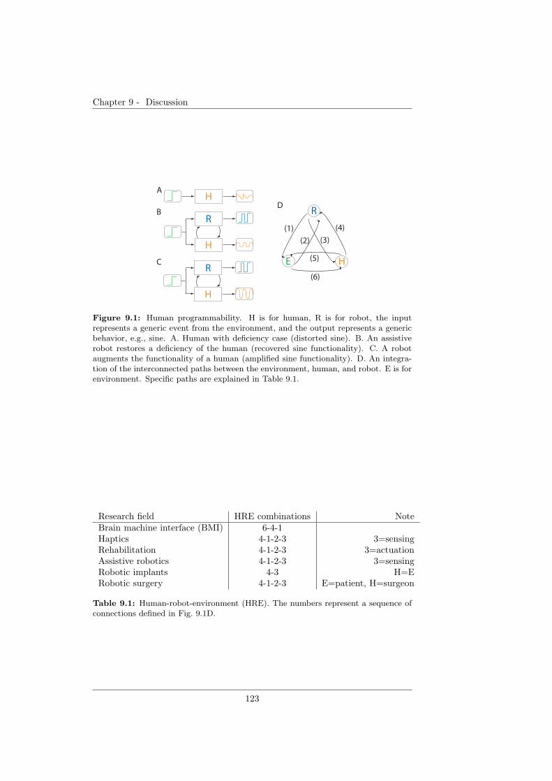
Chapter 9 - Discussion
H
R
H
R
H
A
B
C
R
E H
(1)
(2) (3)
(4)
(5)
(6)
D
Figure 9.1: Human programmability. H is for human, R is for robot, the inputrepresents a generic event from the environment, and the output represents a genericbehavior, e.g., sine. A. Human with deficiency case (distorted sine). B. An assistiverobot restores a deficiency of the human (recovered sine functionality). C. A robotaugments the functionality of a human (amplified sine functionality). D. An integra-tion of the interconnected paths between the environment, human, and robot. E is forenvironment. Specific paths are explained in Table 9.1.
Research field HRE combinations NoteBrain machine interface (BMI) 6-4-1Haptics 4-1-2-3 3=sensingRehabilitation 4-1-2-3 3=actuationAssistive robotics 4-1-2-3 3=sensingRobotic implants 4-3 H=ERobotic surgery 4-1-2-3 E=patient, H=surgeon
Table 9.1: Human-robot-environment (HRE). The numbers represent a sequence ofconnections defined in Fig. 9.1D.
123

Chapter 9 - Discussion
and (re)learning. This takes place in haptic applications, and assistive and re-habilitation robotics. By having control over the feedback, the end effector, andthe mapping between them and the user, the human becomes a programmableliving entity. Through associations, the user could learn sensory-motor routesas models in the central nervous system. For this reason, automatic prosthesesdo not reside in the area of human programmability because the sensing and theactuation is performed exclusively by the prosthetic device, depriving the humanuser of information or action involvement that contributes to the (re)learningprocess. The programmability concept can provide a general framework for cap-turing the restoration and the augmentation of human capabilities using biologicand robotic computational resources. Additionally, this framework can also beuseful for devising methodologies for testing the notion of self. The researchfields presented in Table 9.1 are case studies in the context of this framework.
Logic versus body programmability
The notion of human programmability is compatible with the programmabilitynotion existent in computer science. This can be extended to robotics becauseit is assumed that there is an input that is fed by the human, designer, or anenvironment that modifies or adds or instantiates a functionality and producesa behavior (for the human and robot), e.g, grasp, or a number (for computers)through a computational process. Within this framework, education, at large,can also be viewed as human programmability meant to refine motions, socialinteraction, verbal utterances and more, during human lifetime. The studiesof this thesis, together with the vast literature in human-robot-environmentinteraction, powerfully suggest that natural or artificially-induced correlationsbetween the sensor and motor transformations drive human behavior, classifyingthe human as one of the most adaptable (programmable) living systems. Thisgeneral statement suggests that robots, as embodied agents, could reach adapt-ability by careful design of the sensor and motor units and the programming ofthe links between these units.
9.3 Design principles for human programmabil-
ity
In order to make efficient use of such a framework, design principles need tobe extracted. Some of these design principles will be discussed in the followingsection. The design principles are based on the studies of this thesis, and there-fore are valid under the assumption that vision is not provided to the user ofan upper-limb prosthesis.
Exteroception and proprioception sensing for description of interac-
tion
From our work on upper-limb prostheses, stable grasp, as a sensory-motor trans-formation, was achieved more quickly and adaptively when the human userwas provided with two different types of feedback: exteroceptive (e.g., slip/slipspeed) and proprioceptive (e.g., grip force)-in other words, information that de-scribes the environment (e.g., the slipping object) and information that describes
124

Chapter 9 - Discussion
the human actuation (e.g., user’s force exerted on the object). The two typesof information are related through a physical transformation, e.g., µ = FL
F(the
static friction coefficient equals the friction (load) force to grip force ratio). Thepresence of the two types of sensory information necessitates a sensory-motorcoordination [119] [121]. The two types of feedback may thus be necessary andsufficient conditions for a fast and adaptive stable grasp. The addition of exte-roceptive or proprioceptive senses is likely to provide redundancy or refinementof the sensing capability, and consequently, may contribute to the dexterity inactuation.
The flow charts and diagrams in Fig. 9.2 illustrate this design principle.Research has been centered on relaying grip force information through hapticinterfaces. In this thesis, we showed that grip force feedback is not sufficientfor stable grasp (Fig. 9.2A). Without any knowledge of the grasped object (ex-teroceptive sensing), the prosthesis wearer cannot properly influence the stateof the object via the applied grip force only (proprioceptive sensing). Conse-quently, if the grip force F decreases significantly, the object may drop; if thegrip force F increases significantly, the object may be crushed. Otherwise, theobject is grasped by applying a force that is not guaranteed to be minimal (i.e.,it is energy-wasteful). In this case, the prosthesis user does not know about thestate of the object (Fig. 9.2A, question mark) unless it uses other exteroceptivesenses such as vision. Grasp stability depends on the weight and friction coef-ficient of the held objects. With a prosthetic device, is is difficult to estimatethese variables based on previous models in the central nervous system becauseof the artificial sensory-motor interface and the altered friction coefficients be-tween the object and the artificial prosthesis. Under these conditions, graspstability is related to overcoming perturbations such as slip; therefore, it is crit-ical to relay information about the slipping object’s position or slip speed tousers. A few studies have argued that slip occurrence feedback improves graspstability. However, the work presented in Chapter 2 showed that providingusers with feedback about slip occurrence leads to poorer performance in over-coming slip relative to the case of slip speed provision. Instead, the provisionof slip speed information, which is a fair substitution for location information,offers multiple benefits to grasp stability, e.g., grasp agility, regulation of thegrasp time response, efficient muscle contraction. Being endowed with extero-ceptive knowledge, the prosthesis user is able to evaluate whether the object isgrasped or slips (v > 0) (see Fig. 9.2B). If the speed is positive, the user hasto search within a large search space of grip force values to decrease the speedof the slipping object. Moreover, if the mapping that characterizes the sensory-motor transformation is not available to the user, this search becomes a highlynon-trivial task (∆1 and ∆2 express the unavailability of the mapping betweenthe sensory-motor transformation to the user). If the user manages to stop it(check mark in the figure), the user still has no information on whether the gripforce applied ensures a stable grasp (minimum force) or crushes the object. Incontrast, with both exteroceptive and proprioceptive sensory information, theprosthesis user manages to guide his or her actions towards achieving a stablegrasp (Fig. 9.2C).
125
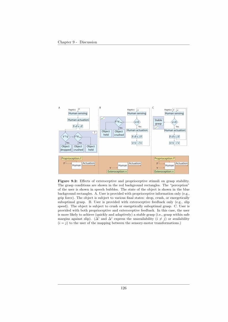
Chapter 9 - Discussion
Human sensing
Human actuation
v>0
Haptics
Yes
F=F+ F
Stable
grasp
Human sensing
Human actuation
Haptics F vF
F=F+ F
Object
dropped
F Fmax
Object
crushed
Object
held
Yes Yes
Human sensing
Human actuation
v>0
Haptics
Yes
v
lim 1
v=v - v1
F=F+ F1
v=v - v2
CA B
Human ActuationF
Human Actuation
Exteroception: v
F
vHuman
Actuation
Exteroception: v
v
F Fmax
Object
crushed
Object
held
Yes
lim
?
F 0lim
Proprioception: F Proprioception: F
Figure 9.2: Effects of exteroceptive and proprioceptive stimuli on grasp stability.The grasp conditions are shown in the red background rectangles. The “perception”of the user is shown in speech bubbles. The state of the object is shown in the bluebackground rectangles. A. User is provided with proprioceptive information only (e.g.,grip force). The object is subject to various final states: drop, crush, or energeticallysuboptimal grasp. B. User is provided with exteroceptive feedback only (e.g., slipspeed). The object is subject to crush or energetically suboptimal grasp. C. User isprovided with both proprioceptive and exteroceptive feedback. In this case, the useris more likely to achieve (quickly and adaptively) a stable grasp (i.e., grasp within safemargins against slip). (∆i and ∆j express the unavailability (i 6= j) or availability(i = j) to the user of the mapping between the sensory-motor transformations.)
126
Chapter 9 - Discussion
Quantified sensing for fine control
We consider the slip speed feedback to be a reverse force feedback representing“negative” forces. Therefore, relaying slip speed information is as significant asrelaying quantified continuous force information. For daily activities in whichusers are engaged, it is imperative that the users receive not only binary eventinformation (e.g., on-off slip detection and on-off contact with objects) aboutgrasping events, but also continuous information about dynamical haptic events(e.g., slip speed of an object and changes of grasp force). We may argue thatan appropriate scheme for overcoming the slip of an object is to always inputlow contraction intensity levels and gradually decrease the speed of the objectuntil the object stops. In this case, slip occurrence feedback should be sufficient.This hypothesis was rejected based on the experimental results of this thesis,according to which, even when the speed of the slipping object was the lowest,the participants receiving slip occurrence feedback recorded the highest percent-age of crushes relative to the vision and slip speed feedbacks. From the workpresented in this thesis, a quantifiable slip feedback provides several advantagesto the prosthesis user: (1) boosts the agility of overcoming slip; (2) increasesthe success in controlling slip with a lower consumption of muscle contractionintensity; (3) ensures lower variability of the muscle contraction input; and (4)controls the reaction time to grip.
Combined “human-in-the-loop” and automatic mechanisms to resolve
voluntary and reflex actions
In prosthetics, the role of haptics is to provide sensory substitution for lostbiological senses associated with the prosthetic device. As a consequence, itcontributes to (1) regulating human behavior such that tasks are performedsuccessfully through the prosthetic device and (2) enabling the bodily integra-tion of the prosthetic device through brain plasticity. This “human-in-the-loop”process, however, is time-consuming due to both technological limitations of in-volved robotic devices (e.g., haptic device, prosthesis) and the traveling time ofa signal from the afferent to the efferent nerves. The cutaneous type of feed-back that has been investigated in this thesis triggers a voluntary reaction of theuser, which may not be sufficiently fast for overcoming slip perturbations char-acterized by high speeds. For these cases, a reflex-based reaction may be moreappropriate, and can be implemented via an automatic grip controller. Thus,a combination between an automatic grasp and a “human-in-the-loop” graspcontrol strategy may be the optimal solution for grip stabilization with pros-thetic hands. Another option that could possibly be a substitute for both graspcontrol strategies is invasive direct nerve stimulation. However, this methodrequires further research and clinical testing to gain acceptance from large usercommunities.
Energy-efficient robotic systems
Energy is a critical feature for the development of robots that are physically(externally or internally) attached to humans and will most likely always be acatalyst for robot design selection. The significance of the economical tactilesensing systems is also apparent for prosthetics. Information availability and
127
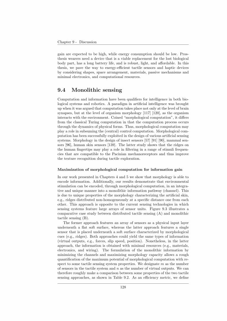
Chapter 9 - Discussion
gain are expected to be high, while energy consumption should be low. Pros-thesis wearers need a device that is a viable replacement for the lost biologicalbody part, has a long battery life, and is robust, light, and affordable. In thisthesis, we pave the way to energy-efficient tactile sensors and haptic devicesby considering shapes, space arrangement, materials, passive mechanisms andminimal electronics, and computational resources.
9.4 Monolithic sensing
Computation and information have been qualifiers for intelligence in both bio-logical systems and robotics. A paradigm in artificial intelligence was broughtup when it was argued that computation takes place not only at the level of brainsynapses, but at the level of organism morphology [117] [120], as the organisminteracts with the environment. Coined “morphological computation”, it differsfrom the classical Turing computation in that the computation process occursthrough the dynamics of physical forms. Thus, morphological computation mayplay a role in subsuming the (central) control computation. Morphological com-putation has been successfully exploited in the design of various artificial sensingsystems. Morphology in the design of insect sensors [57] [91] [90], mammal sen-sors [96], human skin sensors [139]. The latter study shows that the ridges onthe human fingertips may play a role in filtering in a range of stimuli frequen-cies that are compatible to the Pacinian mechanoreceptors and thus improvethe texture recognition during tactile exploration.
Maximization of morphological computation for information gain
In our work presented in Chapters 4 and 5 we show that morphology is able toencode information. Additionally, our results demonstrate that environmentalstimulation can be encoded, through morphological computation, in an integra-tive and unique manner into a monolithic information pathway (channel). Thisis due to unique properties of the morphology characterizing the artificial skin,e.g., ridges distributed non-homogeneously at a specific distance one from eachother. This approach is opposite to the current sensing technologies in whichsensing systems feature large arrays of sensor units. Figure 9.3 illustrates acomparative case study between distributed tactile sensing (A) and monolithictactile sensing (B).
The former approach features an array of sensors as a physical input layerunderneath a flat soft surface, whereas the latter approach features a singlesensor that is placed underneath a soft surface characterized by morphologicalcues (e.g., ridges). Both approaches could yield the same types of information(virtual outputs, e.g., forces, slip speed, position). Nonetheless, in the latterapproach, the information is obtained with minimal resources (e.g., materials,electronics, and wiring). The formulation of the monolithic information byminimizing the channels and maximizing morphology capacity allows a roughquantification of the maximum potential of morphological computation with re-spect to some tactile sensing system properties. We designate m as the numberof sensors in the tactile system and n as the number of virtual outputs. We cantherefore roughly make a comparison between some properties of the two tactilesensing approaches, as shown in Table 9.2. As an efficiency metric, we define
128
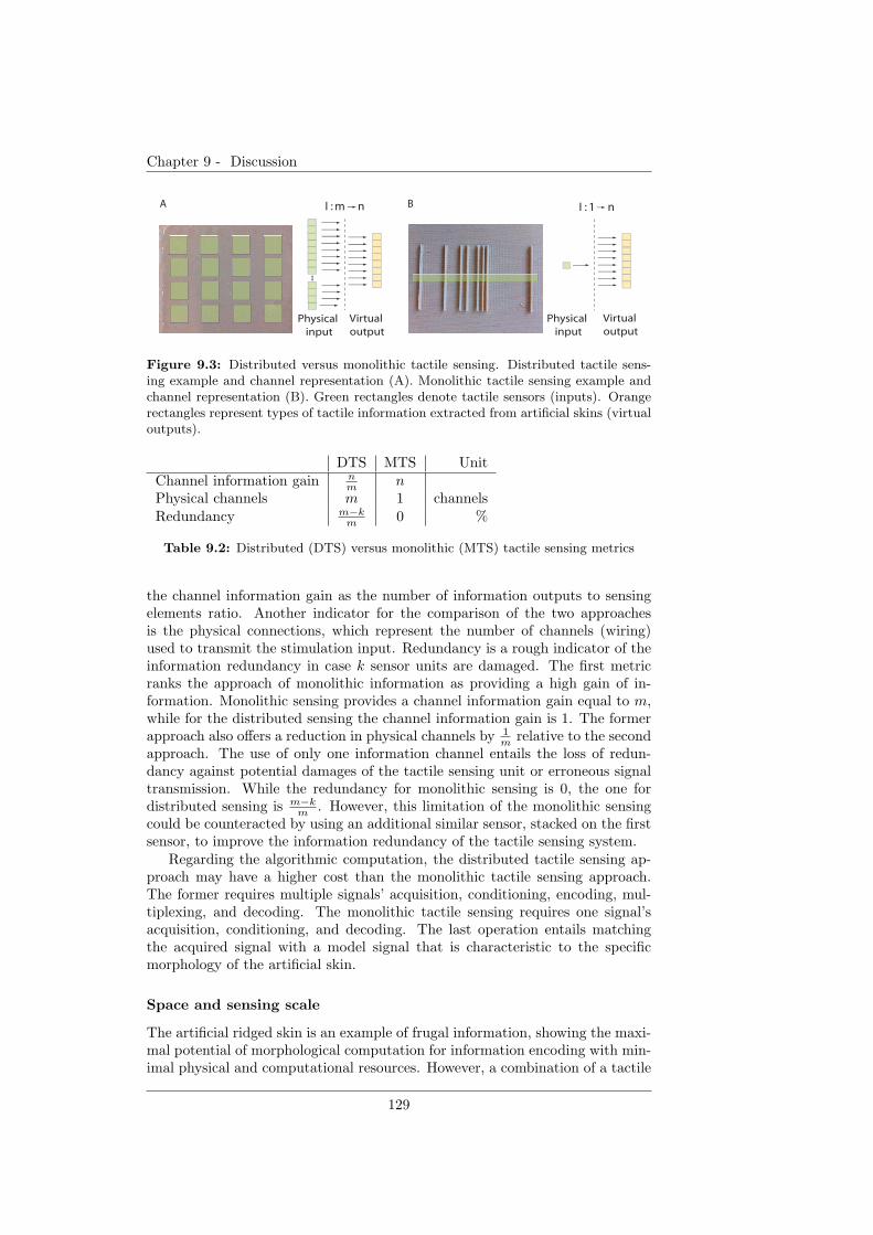
Chapter 9 - Discussion
B
Physical
input
Virtual
output
Physical
input
Virtual
output
A I : m n I : 1 n
Figure 9.3: Distributed versus monolithic tactile sensing. Distributed tactile sens-ing example and channel representation (A). Monolithic tactile sensing example andchannel representation (B). Green rectangles denote tactile sensors (inputs). Orangerectangles represent types of tactile information extracted from artificial skins (virtualoutputs).
DTS MTS UnitChannel information gain n
mn
Physical channels m 1 channelsRedundancy m−k
m0 %
Table 9.2: Distributed (DTS) versus monolithic (MTS) tactile sensing metrics
the channel information gain as the number of information outputs to sensingelements ratio. Another indicator for the comparison of the two approachesis the physical connections, which represent the number of channels (wiring)used to transmit the stimulation input. Redundancy is a rough indicator of theinformation redundancy in case k sensor units are damaged. The first metricranks the approach of monolithic information as providing a high gain of in-formation. Monolithic sensing provides a channel information gain equal to m,while for the distributed sensing the channel information gain is 1. The formerapproach also offers a reduction in physical channels by 1
mrelative to the second
approach. The use of only one information channel entails the loss of redun-dancy against potential damages of the tactile sensing unit or erroneous signaltransmission. While the redundancy for monolithic sensing is 0, the one fordistributed sensing is m−k
m. However, this limitation of the monolithic sensing
could be counteracted by using an additional similar sensor, stacked on the firstsensor, to improve the information redundancy of the tactile sensing system.
Regarding the algorithmic computation, the distributed tactile sensing ap-proach may have a higher cost than the monolithic tactile sensing approach.The former requires multiple signals’ acquisition, conditioning, encoding, mul-tiplexing, and decoding. The monolithic tactile sensing requires one signal’sacquisition, conditioning, and decoding. The last operation entails matchingthe acquired signal with a model signal that is characteristic to the specificmorphology of the artificial skin.
Space and sensing scale
The artificial ridged skin is an example of frugal information, showing the maxi-mal potential of morphological computation for information encoding with min-imal physical and computational resources. However, a combination of a tactile
129
Chapter 9 - Discussion
Figure 9.4: Distributed and monolithic tactile sensing. An example of artificial skinfeaturing four sensing elements (shown in green color), each being associated with aunique arrangement of ridges.
array and skin morphology may contribute not only to information and effi-ciency gain, but also to a gain in information resolution. This fusion has thepotential to increase the spectral resource and enable tactile capabilities such astexture recognition. The combination of the two approaches would also improvethe accuracy, redundancy, and robustness of the tactile sensing system.
Figure 9.4 illustrates the concept of a combination between distributed andmonolithic tactile sensing. Each sensor is associated with a unique patternof ridges. This way, the signal acquired by a transduction technique is able toderive more information than if no morphological patterns were present. Overall,the tactile sensing resembles the human tactile sense in that rich environmentalinformation is integrated from a spatial region. The uniqueness of informationassociated with each sensor depends on the density and the arrangement ofthe corresponding spatial cues, thus providing a similarity with the density andspatial distribution of the mechanoreceptors in the human skin. This combinedapproach entails miniaturizing the current version of the artificial skin, such thatspatial cues fit in regions smaller than 5 mm [141]. The current technologies,e.g., microelectrical systems (MEMS), microfabrication, etc., provide methodsfor achieving such artificial skins. The ridged patterns on the skin currentlybehave as a low-frequency filter, detecting location, slip occurrence, and speed.As the scale decreases, these patterns play the role of a high-frequency filter andcould identify textures.
The artificial skin featuring ridges shows the potential of complex space ge-ometry (shapes) to efficiently encode environmental information in dynamicalevents. In this respect, robot locomotion has made considerable progress infocusing attention on space distances, shapes, and stiffness for limb compo-nents [68]. Following the same principles, it would be interesting to developmechanical brains that exploit not only time functions, which is currently per-formed through algorithms, but also physical space and mechanisms that mimicbrain functionality. This way we could gain more insight into physical and chem-ical computation in the brain and their relations with sensing and actuation.
9.5 Human skin as a programming medium
The human’s interaction with the environment (e.g., grasping and manipulation,walking) is facilitated by cutaneous mechanoreceptors that provide informationabout contact location, pressure, and events such as making and breaking con-tact. This intricate network of mechanoreceptors provides a rich spectrum ofinformation to a healthy human; however, it is a significant challenge to reverse-engineer the underlying sensing mechanisms in order to create artificial, yet real-
130
Chapter 9 - Discussion
istic tactile sensations for prosthesis wearers that have lost the biological tactilesense. Apart from the difficulty of tapping the right types of mechanoreceptors,an additional challenge in the design of haptic devices is the skin, as it is anembodied medium between the haptic device and the mechanoreceptors, withintrinsic properties.
There are numerous studies dedicated to the physiologic characterizationof the skin under force or vibration stimuli. In most studies, these stimuliare applied through skin tap procedures [78]. However, real scenarios, such asgrasping, manipulation, and walking, involve a far richer interaction betweenthe skin and environment, such as for example, substantial normal and lateral(shear) motions. Our studies have indicated that a stimulus in motion on theskin may carry enhanced information. These properties should be consideredand exploited in the future development of haptic devices, and are listed below.
Vibrations as force and spatial cues carriers The objective experimentalcharacterization of the artificial skin described in [43] suggested that nor-mal and lateral stimuli in motion may carry rich environmental infor-mation. The experimental results suggest that vibrations elicited by amoving contact point on the skin are information carriers that integrateboth force and spatial cues. Analysis indicated that vibration frequencyalone may enable discrimination between some speeds and between somenormal forces. We found that vibration amplitude can be used to differ-entiate some speeds and normal forces. In addition, spatial cues resultingfrom a series of vibration events display accurate information about thespeed of contact points.
Skin’s natural frequency In our experiments, the vibration amplitude of aconstant weight, moving on the skin, and plotted with respect to speedwas a parabola with a global maximum at 15 mm/s. We surmise that thisis a consequence of the resonant frequency of the artificial skin and maydepend on various factors (e.g., material properties and thickness). Theresonant frequency of natural skin has been studied physiologically in [159]and its presence could be considered in the design of haptic devices.
Skin compliance In our previous study [93], we measured the force ampli-tude of a soft structure tapping on a rigid flat surface as the structure wasengaged in a concentric motion tangential to the flat surface. The plotsshowed a linear dependence between the force amplitude and the rotationspeed of the soft structure. However, similar experimental procedures per-formed on the skin [45], instead of on a flat surface, indicated that thislinear relation is no longer valid if the stimulation is transmitted to thehuman skin. From our experimental observations, the variation of the nor-mal force amplitude within a session and between sessions depended onthe resistive forces between the force tactor and the skin due to the initialpressure exerted by the wearable haptic device’s cuff around the forearm,and on the position of the force tactor with respect to the forearm, whichfeatures varying softness of the skin. Consequently, we opted to encodegrip force information in tap frequency, rather than in tap intensity. Thischoice was supported by a pilot user study [93], which shows that forcefrequency, rather than force magnitude, can be used as a force evaluationcue. The result indicates that frequency had a better tactile display reso-
131

Chapter 9 - Discussion
lution than force magnitude. Additionally, the periodic stimulation suffersless from habituation, in contrast to static stimuli, which produce rapidadaptation of tactile sense [79].
Human skin is a medium with rich properties. Its soft material, sensitivityto pressure, motion, vibration and stretch, and natural frequency can all beexploited to input stimuli and program the consequent human behavior. Su-perposing these properties may provide rich sensations, though they may alsogive rise to stimulation effects that are difficult to predict in the design andfunctionality of a haptic device. It is therefore interesting to think of skin as aprogramming-embodied medium that transmits a large spectrum of informationor sensations encoded in space, spatial density, intensity, and frequency.
9.6 Economical tactile displays
The haptic device is an extension of the prosthetic device that relays sensoryfeedback correlated to remote motor outputs of the prosthetic device. The hap-tic device represents a “programming tool” because the sensory input can drivethe motor behavior of the human and can generate neurocognitive alterationssuch as the bodily incorporation of the prosthesis. As an attachment to the hu-man body, the device falls into the same class of robots whose critical feature isenergy efficiency. In Chapter 8, we proposed a haptic device prototype using softtactors that features energy efficiency by relying on a single motor to providetactile stimulation variety. Thus, the haptic device transmits grasp informationto the prosthesis user (e.g., grip force, slip occurrence, and slip speed). In thefollowing section, we provide some design guidelines, compiled from our studies,that can be considered in constructing energy-efficient tactile feedback devices.
Contact shape
In Chapter 7, we investigated means by which to relay grip force using softtactors that transmit tapping movements on the skin as they are rotated by a DCmotor. Our study considered the physical influence of the shape of the tactor’sstimulus on force generation. The tactors represented nubs on a rotating belt.The four types of nubs considered- square (A), long rectangle (B), wide rectangle(C), and hemispherical (D)- generated force profiles with various properties.The belt with square nubs (A) yielded linear monotonic force magnitudes withrespect to rotation speed and the highest force magnitude resolution for bothaverage and peak force. Compared to this belt, the one with long rectangularnubs (B) reduced both average and peak force. It provided a smoother forcetransmission due to a low average and peak force magnitude and low magnituderesolution. The belts with wide rectangular (C) and hemispherical (D) nubsamplified the force signal relative to the type A belt. The type C belt produceda high duty rate by maintaining contact with the rigid body over a longer time.However, the force magnitude did not increase significantly as speed increased.
Soft materials
Soft materials represent a potential source for energy-efficient robots through theexploitation of elasticity and momentum. We used silicone in the construction
132
Chapter 9 - Discussion
of the tactors of the haptic device in order to create grip force as a tactilestimulation. Square silicone nubs, equally distributed on the rotating belt, hit arigid bar during their motion. The rigid bar, referred to as the force transmitter,had direct and perpendicular contact with the skin. Thus, as the rigid barwas periodically hit by the silicone tactor, a normal force was exerted on thehuman skin. The advantage of a soft material in this scenario is that it cancreate a realistic pressure sensation with a potentially reduced current from themotor. As the nub hits the rigid body, it gains increasing acceleration due tothe friction between the nub and the rigid bar. This acceleration is transmittedto the following nub on the rotating belt, thus creating a larger force at itssubsequent contact with the rigid bar. Consequently, the force exerted on theskin may potentially be amplified through the nature of the soft material. Inaddition, the fact that the silicone nubs become stiffer as the speed of the motorincreases could also be used for the contact force amplification.
Mechanisms
It is common for current tactile displays to use a 1 : 1 ratio for the used actuatorversus relayed information ratio [152] [126] [11]. We approached the creation ofa wearable tactile display for prosthetic grasp from an economical prospectivein order to provide prosthesis wearers with an environmental tactile image usingminimal resources. In the development of the haptic device presented in Chap-ter 8, we used motor shaft rotation as a global actuation scheme. We derivedthis global actuation scheme in order to realize vertical and horizontal actuationfor small-area and wide-area stimulation for relaying grip force and slip speed,respectively. This was achieved using two belts featuring different lengths andtactors, rotating on the same shaft. Their mutually exclusive operation wasattained using local passive actuation by means of a tooth washer to decouplethe belts, and a ratchet and pawl mechanism to keep one belt fixed as the otherone is operating.
Textures
Texture is an additional morphological parameter to be taken into account fortactile robots. Various textures for the tactors of the slip belt of the hapticdevices have been tested in pilot experiments. Among wood, brush, and foamtactors, foam showed a better performance for creating a realistic slip sensation.Previous studies [134] also showed that the sensitivity to slip speed highly de-pends on the surface texture. Thus, the rates of the slip speed’s identificationfor the haptic device presented in this thesis could arguably be improved if thesoft foam tactors could further feature surface textures.
An interesting question that can be raised is whether the haptic device, as acomplement of the prosthetic device, can be incorporated as a part of the body.Functionally, from the perspective of the human, the prosthetic hand enablesthe grasp actuation, whereas the haptic device enables the grasp sensing. To ourknowledge, there have not been studies on this topic. However, it is probablethat the haptic device could not be incorporated into the body schema becauseits motor action does not physically support grasping, which is the voluntaryand expected behavioral action from the prosthesis wearer.
133
Chapter 9 - Discussion
9.7 Conclusion
Human-robot-environment interaction has paved the way for the study of theself by offering the potential of human programmability. In contrast to otherdisciplines, such as genomics or regenerative medicine, robotics represents apromising tool for the systematic investigation of the paradigm of “brain, body,and self” through controlled designs or artificial interfaces and devices. Thistool encompasses physical filter design (e.g., artificial skins), haptic displays,customized actuators (e.g., manipulators), and artificial sensory-motor map-pings, thus making the human a highly programmable embodied agent.
The focus of this thesis has been grasp stability in upper-limb prosthesesfrom a unified perspective of tactile sensing and display. The obtained resultssuggest that the sensory-motor transformations generated by grasp with pros-theses may provide suitable means for inquiring the meaning of the self andthe environment. In this regard, the self can be described through the in-teraction with the environment. A key attribute in defining the self and itsinterconnection to the environment is the energy efficiency. Energy efficiencycan be achieved by the user if the body and the environment engaged in theinteraction can be minimally but holistically described by an exteroceptive andproprioceptive sense through a sensory-motor transformation. The energy effi-ciency of the human-environment interaction and of prosthetic devices has beena leading factor for the acceptance of prostheses. Consequently, engineering theself may also imply building efficient robotic devices that can restore or aug-ment human functionality with minimal resources. This thesis shows variousdesign principles for energy-efficient human programmability in the context ofsensing in upper-limb prosthetics. Morphology can be exploited for frugal infor-mation. Soft materials, shapes, and spacing configurations represent powerfulcomputational resources for encoding information from the environment and forprogramming human-environment interactions in an energy-efficient manner.
The thesis deepens the understanding of sensorimotor transformations inprosthetic systems as a basis for self-restoration or self-augmentation. Addi-tionally, it shows the capital of morphology exploitation as means for buildingefficient interface schemes in human-robot-environment systems.
134

Chapter 9 - Discussion
Figure 9.5: Soft Self Portrait, Salvador Dali, 1941
135

Chapter 9 - Discussion
136
Bibliography
[1] J. Abbott, P. Marayong, and A. Okamura. Haptic virtual fixtures forrobot-assisted manipulation. In S. Thrun and R. Brooks and H. Durrant-Whyte, Eds., Robotics Research: Results of the 12th International Sym-posium ISRR, pages 49–64. 2007.
[2] N. Adams, C. Brown, and K. Nagy. Energy expenditure of free-rangingwandering albatrosses diomedea exulans. Physiological Zoology, 59(6):583–591, 1986.
[3] Q. An, Y. Matsuoka, and C. Stepp. Multi-day training with vibrotactilefeedback for virtual object manipulation. In Proceedings of the IEEEInternational Conference on Rehabilitation Robotics, pages 1–5, 2011.
[4] C. Antfolk, C. Balkenius, G. Lundborg, B. Rosen, and F. Sebelius. Designand technical construction of a tactile display for sensory feedback in ahand prosthesis system. BioMedical Engineering OnLine, 9(50), 2010.
[5] A. H. Arieta. Development of a multi-channel functional electrical stimu-lation system for prosthetic applications of limbs. Doctoral Dissertation.,2007.
[6] A. H. Arieta, C. Dermitzakis, D. Damian, M. Lungarella, and R. Pfeifer.Sensory-motor coupling in rehabilitation robotics. Handbook of ServiceRobotics, I-Tech Education and Publishing, Vienna, Austria, 2008.
[7] A. H. Arieta, R. Kato, H. Yokoi, and W. Yu. Development of a multi-dofelectromyography prosthetic system using the adaptive joint mechanism.Applied Bionics and Biomechanics, 3(2):101–111, 2006.
[8] A. Asbeck, S. Dastoor, A. Parness, L. Fullerton, N. Esparza, D. Soto,B. Heyneman, and M. Cutkosky. Climbing rough vertical surfaces withhierarchical directional adhesion. In IEEE International Conference onRobotics and Automation, pages 2675 – 2680, 2009.
[9] D. Atkins, D. Heard, and W. Donovan. Epidemiologic overview of individ-uals with upper-limb loss and their reported research priorities. Journalof Prosthetics and Orthotics, 8(2-11):718–723, 1996.
[10] A.-S. Augurelle, A. Smith, T. Lejeune, and J.-L. Thonnard. Importanceof cutaneous feedback in maintaining a secure grip during manipulationof hand-held objects. J. of Neurophysiology, 89:665–671, 2003.
137
BIBLIOGRAPHY
[11] R. Baavour, M. Fuchs, and U. Ben-Hanan. Grip-slip: A slip/shear tactiledisplay master unit for grip tasks. In IEEE Proceedings of the Mediter-ranean Conference on Control and Automation, pages 1 – 6, 2007.
[12] P. BachyRita. Sensory plasticity. applications to a vision substitutionsystem. Acta Neurol Scand., 43(4):417–426, 1967.
[13] L. Bahrick and J. Watson. Detection of intermodal proprioceptive-visualcontingency as a basis of self perception in infancy. Developmental Psy-chology, 21:963–973, 1985.
[14] B.B.Edin, R. Howe, G. Westling, and M. Cutkosky. A physiologicalmethod for relaying frictional information to a human operator. IEEETransactions on Systems, Man, and Cybernetics, 23(2):427–432, 1993.
[15] L. Beccai, S. Roccella, L. Ascari, P. Valdastri, A. Sieber, M. Carrozza,and P. Dario. Development and experimental analysis of a soft compli-ant tactile microsensor for anthropomorphic artificial hand. IEEE/ASMETransactions on Mechatronics,, 13(2):158–168, 2008.
[16] B. Bethea, A. Okamura, M. Kitagawa, T. Fitton, S. Cattaneo, V. Gott,W. Baumgartner, and D. Yuh. Application of haptic feedback to roboticsurgery. J Laparoendosc Adv Surg Tech A, page 191195, 2004.
[17] A. Bicchi and V. Kumar. Robotic grasping and contact: a review. InIEEE Proceedings of International Conference on Robotics and Automa-tion, pages 348 – 353, 2000.
[18] A. Bicchi, J. Salisbury, and P. Dario. Augmentation of grasp robustnessusing intrinsic tactile sensing. In IEEE Proceedings of International Con-ference on Robotics and Automation, pages 302 – 307, 1989.
[19] E. Biddiss and T. Chau. Upper limb prosthesis use and abandonment: asurvey of the last 25 years. Prosthet Orthot Int, 31(3):236–257, 2007.
[20] A. Blank, A. Okamura, and K. Kuchenbecker. Identifying the role of pro-prioception in upper-limb prosthesis control: Studies on targeted motion.ACM Transactions on Applied Perception, 7(3), 2010.
[21] D. Bloor, K. Donnelly, P. J. Hands, P. Laughlin, and D. Lussey. A met-alpolymer composite with unusal properties. J. Phys. D: Appl. Phys.,38(6):2851–2860, 2005.
[22] M. Botvinick and J. Cohen. Rubber hands “feel” touch that eyes see.Nature, 391:756, 1998.
[23] D. Brown and W. Christian. Simulating what you see. In Proceedings ofMPTL 16 and HSCI, 2011.
[24] E. Brown, N. Rodenberg, J. Amend, A. Mozeika, E. Steltz, M. Zakin,H. Lipson, and H. Jaeger. Universal robotic gripper based on the jammingof granular material. Proceedings of the National Academy of Sciences(PNAS), 107(44):18809–18814, 2010.
138
BIBLIOGRAPHY
[25] L. Cardinali, F. Frassinetti, C. Brozzoli, C. Urquizar, A. Roy, andA. Farne. Tool-use induces morphological updating of the body schema.Current Biology, 19(12):R478–R479, 2009.
[26] J. Carpaneto, S. Micera, F. Zaccone, F. Vecchi, and P. Dario. A sensorizedthumb for force closed-loop control of hand neuroprostheses. IEEE Trans-actions on Neural Systems and Rehabilitation Engineering, 11(4):346 –353, 2003.
[27] M. Carrozza, B. Massa, S. Micera, R. Lazzarini, M. Zecca, and P. Dario.The development of a novel prosthetic hand-ongoing research and prelimi-nary results. IEEE/ASME Transactions on Mechatronics, 7(2):108 – 114,2002.
[28] M. C. Carrozza, G. Cappiello, S. Micera, B. B. Edin, L. Beccai, andC. Cipriani. Design of a cybernetic hand for perception and action. BiolCybern, 95:629–644, 2006.
[29] M. Cartmill. The volar skin of primates: its frictional characteristics andtheir functional significance. American Journal of Physical Anthropology,50:497–510, 1979.
[30] A. Chatterjee, V. Aggarwal, A. Ramos, S. Acharya, and N. Thakor. Abrain-computer interface with vibrotactile biofeedback for haptic informa-tion. Journal of Neuroengineeting and Rehabilitation, 4(40), 2007.
[31] A. Chatterjee, P. Chaubey, J. Martin, and N. Thakor. Quantifying pros-thesis control improvements using a vibrotactile representation of gripforce. In IEEE Region 5 Conference, pages 1–5, 2008.
[32] M.-Y. Cheng, C.-L. Lin, Y.-T. Lai, and Y.-J. Yang. A polymer-basedcapacitive sensing array for normal and shear force measurement. Sensors,10(11):10211–10225, 2010.
[33] D. Childress. Expert analysis of the tirr national upper-limb amputeedatabase. In Archived at The Institute for Rehabilitation and Research inHouston, 1994.
[34] M. Ciocarlie and P. Allen. Hand posture subspaces for dexterous roboticgrasping. International Journal of Robotics Research, 28(7):851–867, 2009.
[35] C. Cipriani, F. Zaccone, S. Micera, and M. Carrozza. On the sharedcontrol of an emg controlled prosthetic hand: analysis of user-prosthesisinteraction. IEEE Transactions on Robotics, 24(1):170–184, 2008.
[36] F. Clark and K. Horch. Kinesthesia. In K. B. Boff, L. Kaufman andJ. P. Thomas (Eds.), Handbook of Human Perception and Performance:Sensory Processes and Perception. John Wiley and Sons, Inc, New York,USA, 1986.
[37] S. Collins, A. Ruina, R. Tedrake, and M. Wisse. Efficient bipedal robotsbased on passive-dynamic walkers. Science, 307(5712):1082–1085, 2005.
139
BIBLIOGRAPHY
[38] D. P. J. Cotton, A. Cranny, N. M. White, and P. H. Chappell. A thick-film piezoelectric slip sensor for a prosthetic hand. IEEE Sensors Journal,7(5):752–761, 2007.
[39] M. Cutkosky. On grasp choice, grasp models, and the design of hands formanufacturing tasks. IEEE Transactions on Robotics and Automation,5(3):269 – 279, 1989.
[40] M. R. Cutkosky, R. D. Howe, and W. Provancher. Force and tactilesensors, Springer Handbook of Robotics, B. Siciliano and O. Khatib,.Springer-Verlag, Berlin/Heidelberg, Germany, 2008.
[41] R. Dahiya, G. Metta, M. Valle, and G. Sandini. Tactile sensing fromhumans to humanoids. IEEE Trans. on Robotics, 26(1):1–20, 2010.
[42] D. Damian, A. Arieta, H. Martinez, and R. Pfeifer. Slip speed sensoryfeedback for prosthetic applications. IEEE Transactions on BiomedicalEngineering, 2012. accepted.
[43] D. Damian, A. H. Arieta, and A. Okamura. Design and evaluation of amulti-modal haptic skin stimulation apparatus. In Proceedings of the In-ternational Conference of the IEEE Engineering in Medicine and BiologySociety, pages 3455–3458, 2011.
[44] D. Damian, M. Fischer, K. Dermitzakis, A. Hernandez-Arieta, andR. Pfeifer. Force and slip feedback guidance role in grasp intensity andtime response. ACM Transactions on Applied Perception, 2012. to besubmmited.
[45] D. Damian, M. Ludersdorfer, Y. Kim, A. H. Arieta, R. Pfeifer, and A. Oka-mura. Wearable haptic device for cutaneous force and slip feedback. InProc. of the IEEE International Conference on Robotics and Automation(ICRA), page in press, 2012.
[46] D. Damian, H. M. Salazar, K. Dermitzakis, A. H. Arieta, and R. Pfeifer.Artificial ridged skin for slippage speed detection in prosthetic hand ap-plications. In Proc. of the 2010 IEEE/RSJ International Conference onIntelligent Robots and Systems (IROS), pages 904–909, 2010.
[47] D. D. Damian, T. Newton, R. Pfeifer, and A. Okamura. Intrinsic slip andlocation detection with a non-uniformly ridged artificial skin. Interna-tional Journal of Robotics Research, 2012. to be submmited.
[48] D. Dennett. The Intentional Stance. MIT Press, Cambridge, USA, 1989.
[49] K. Dermitzakis, M. Morales, and A. Schweizer. Frictional interaction inthe tendon-sheath system of the human finger and its use in robotics. InInternational Conference on Morphological Computation, 2011.
[50] A. Dollar and R. Howe. The highly adaptive sdm hand: Design andperformance evaluation. International Journal of Robotics Research,29(5):585597, 2010.
140
BIBLIOGRAPHY
[51] S. Dorgan and R. Reilly. A model for human skin impedance duringsurface functional neuromuscular stimulation. IEEE Transactions on Re-habilitation Engineering, 7(3), 1999.
[52] S. Douady and Y. Couder. Phyllotaxis as a physical self-organized growthprocess. Physical Review Letters, 68(13):2098 – 2101, 1992.
[53] J. Duque, D. Masset, and J. Malchaire. Evaluation of handgrip force fromemg measurements. Applied Ergonomics, 26(1):61–66, 1995.
[54] B. Edin, L. Ascari, L. Beccai, S. Roccella, J.-J. Cabibihan, and M. Car-rozza. Bio-inspired sensorization of a biomechatronic robot hand for thegrasp-and-lift task. Brain Research Bulletin, 75(6):785–795, 2008.
[55] F. Faul, E. Erdfelder, A.-G. Lang, and A. Buchner. G*power 3: A flexiblestatistical power analysis program for the social, behavioral, and biomed-ical sciences. Behavior Research Methods, 39(2):175–191, 2007.
[56] R. Fearing and J. M. Hollerbach. Basic solid mechanics for tactile sensing.The International Journal of Robotics Research, 4(3):40–54, 1985.
[57] N. Franceschini, J. M. Pichon, and C. Blanes. From insect vision to robotvision. Philosophical Transactions: Biological Sciences, 337(1281):283–294, 1992.
[58] M. Gabiccini and A. Bicchi. On the role of hand synergies in the optimalchoice of grasping forces. Autonomous Robots, 31(2):235–252, 2011.
[59] F. Geldard. Some neglected possibilities of communication. Science,131(3413):1583–1588, 1960.
[60] V. Gilja, C. Chestek, I. Diester, J. Henderson, K. Deisseroth, andK. Shenoy. Myoelectric forearm prostheses: State of the art from auser-centered perspective. IEEE Transactions on Biomedical Engineer-ing, 58(7):1891 1899, 2011.
[61] B. Gleeson, S. Horschel, and W. Provancher. Perception of directionfor applied tangential skin displacement: Effects of speed, displacementand repetition. IEEE Transactions on Haptics- World Haptics Spotlight,3(3):177–188, 2010.
[62] B. Gray and R. Fearing. A surface micromachined microtactile sensorarray. In Proceedings of the IEEE International Conference on Roboticsand Automation, pages 1 – 6, 1996.
[63] C. Haeger-Ross, K. Cole, and R. Johansson. Grip-force responsesto unanticipated object loading: load direction reveals body- andgravity-referenced intrinsic task variables. Experimental Brain Research,110(1):142–150, 1996.
[64] B. Hannaford and A. Okamura. Chapter 30: Haptics. In In B. Sicilianoand O. Khatib, Eds., Handbook of Robotics. Springer, 2008.
[65] O. B. Healthcare. URL:http://www.ottobockus.com/, 2008.
141
BIBLIOGRAPHY
[66] W. Howard and V. Kumar. On the stability of grasped objects. IEEETransactions on Robotics and Automation, 12(6):904 – 917, 1996.
[67] J. Hunter, J. Katz, and K. Davis. The effect of tactile and visual sensoryinputs on phantom limb awareness. Brain, 126(3):579–589, 2003.
[68] F. Iida and R. Pfeifer. Cheap rapid locomotion of a quadruped robot:Self-stabilization of bounding gait. In Proceedings of the 8th InternationalConference on Intelligent Autonomous Systems (IAS-8), pages 642–649,2004.
[69] I. Inc. http://www.interlinkelec.com/catalog/Force-Sensors, Camarillo,CA.
[70] A. Inmann and M. Haugland. Functional evaluation of natural sensoryfeedback incorporated in a hand grasp neuroprosthesis. Medical Engineer-ing and Physics, 26(6):439–447, 2003.
[71] P. Jenmalm, A. Goodwin, and R. Johansson. Control of grasp stabilitywhen humans lift objects with different surface curvatures. J Neurophysiol,79:1643–1652, 1998.
[72] R. Johansson and K. Cole. Grasp stability during manipulative actions.Canadian Journal of Physiology and Pharmacology, 72(5):511–524, 1994.
[73] R. Johansson and K. Cole. Grasp stability during manipulative actions.Can J Physiol Pharmacol, 72(5):511–524, 1994.
[74] R. Johansson and A. Valbo. Tactile sensory coding in the glabrous skinof the human hand. Trends in Neuroscience, 6:27–32, 1983.
[75] R. Johansson and G. Westling. Roles of glabrous skin receptors and senso-rimotor memory in automatic control of precision grip when lifting rougheror more slippery objects. Experimental Brain Research, 56(3):550–564,1984.
[76] R. Johansson and G. Westling. Roles of glabrous skin receptors and senso-rimotor memory in automatic control of precision grip when lifting rougheror more slippery objects. Experimental Brain Research, 56:550–564, 1984.
[77] R. Johansson and G. Westling. Signals in tactile afferents from the fingerseliciting adaptive motor responses during precision grip. ExperimentalBrain Research, 66(141–154), 1987.
[78] L. Jones and S. Lederman. Human Hand Function. Oxford UniversityPress, New York, USA, 2006.
[79] K. A. Kaczmarek, J. G. Webster, P. B. y Rita, and W. J. Tompkins.Electrotactile and vibrotactile displays for sensory substitution systems.IEEE Trans. on Biomedical Engineering, 38:1–16, 1991.
[80] E. Kandel, J. Schwartz, and T. Jessell. Principles of Neural Science, 4thedn. McGraw-Hill, New York,USA, 2000.
142
BIBLIOGRAPHY
[81] D.-H. Kim, J.-H. Ahn, W. Choi, H.-S. Kim, T.-H. Kim, J. Song, Y. Huang,Z. Liu, C. Lu, and J. Rogers. Stretchable and foldable silicon integratedcircuits. Science, 320(5875):507–511, 2008.
[82] K.Kim, J. Colgate, J. Santos-Munne, A. Makhlin, and M. Peshkin. Onthe design of miniature haptic devices for upper extremity prosthetics.IEEE/ASME Transactions on Mechatronics, 15(1):27–39, 2010.
[83] A. Kron and G. Schmidt. Multi-fingered tactile feedback from virtual andremote environments. In Proceedings of the 11th Symposium on HapticInterfaces for Virtual Environment and Teleoperator Systems, 2003.
[84] K. J. Kuchenbecker, J. Gewirtz, W. McMahan, D. Standish, P. Martin,J. Bohren, P. J. Mendoza, and D. I. Lee. Verrotouch: High-frequencyacceleration feedback for telerobotic surgery. In Proceedings of the 8thinternational conference on Haptics, 2010.
[85] P. Kyberd, M. Evans, and S. te Winkel. An intelligent anthropomorphichand, with automatic grasp. Robotica, 16:531–536, 1998.
[86] P. J. Kyberd, D. Gow, H. Scott, M. Griffiths, L. Sperling, L. Sandsjo,C. Almstrom, C. Wartenberg, and S. Jonsson. A comparison of upperlimb prostheses users in europe. InMyoelectr. Controls Symp. Fredericton,1999.
[87] S. Lederman, R. Klatzky, C. Tong, and C. Hamilton. The perceived rough-ness of resistive virtual textures: Ii. effects of varying viscosity with aforce-feedback device. ACM Trans. on Applied Perception, 3(1):15–30,2006.
[88] H.-K. Lee, J. Chung, S.-I. Chang, and E. Yoon. Real-time measure-ment of the three-axis contact force distribution using a flexible capacitivepolymer tactile sensor. Journal of Micromechanics and Microengineering,21(3):035010, 2011.
[89] J. Li, M. Cutkosky, J. Ruutiainen, and R. Raisamo. Using haptic feed-back to improve grasp force control in multiple sclerosis patients. IEEETransactions on Robotics, 25(3):593–601, 2009.
[90] L. Lichtensteiger and R. Pfeifer. An optimal sensor morphology improvesadaptability of neural network controllers. Proceeding ICANN ’02 Pro-ceedings of the International Conference on Artificial Neural Networks,337(1281):283–294, 1992.
[91] L. Lichtensteiger and R. Pfeifer. An optimal sensor morphology improvesadaptability of neural network controllers. In Proceeding ICANN ’02 Pro-ceedings of the International Conference on Artificial Neural Networks,pages 850 – 855, 2002.
[92] D. Lipomi, M. Vosgueritchian, B.-K. Tee, S. Hellstrom, J. Lee, C. Fox,and Z. Bao. Skin-like pressure and strain sensors based on transparentelastic films of carbon nanotubes. Nature Nanotechnology, 6:788792, 2011.
143
BIBLIOGRAPHY
[93] M. Ludersdorfer, D. Damian, A. H. Arieta, R. Pfeifer, and A. Okamura.Cutaneous force display via shaped contacts. In Proceedings of the Inter-national Conference on Morphological Computation, pages 127–129, 2011.
[94] V. J. Lumelsky, M. S. Shur, and S. Wagner. Sensitive skin. IEEE SensorsJournal, 1(1):41–51, 2001.
[95] G. Lundborg and B. Rosen. Sensory substitution in prosthetics. HandClin., 3:481–488, 2001.
[96] M. Lungarella, V. Hafner, R. Pfeifer, and H. Yokoi. An artificial whiskersensors in robotics. In Proceedings of the IEEE/RSJ International Con-ference on Intelligent Robots and Systems, pages 2931–2936, 2002.
[97] M. MacIver, N. Patankar, and A. Shirgaonkar. Energy-information trade-offs between movement and sensing. PLoS Comput Biol, 6(5):e1000769,2010.
[98] K. MacLean. Designing with haptic feedback. In Proceedings of IEEERobotics and Automation, 2000.
[99] D. A. Mahns, N. M. Perkins, V. Sahai, L. Robinson, and M. J. Rowe.Vibrotactile frequency discrimination in human hairy skin. Journal ofNeurophysiology, 95(3):1442–1540, 2005.
[100] R. Maldonado-Lopez, F. Vidal-Verdu, G. Linan, E. Roca, andA. Rodriguez-Vazquez. Early slip detection with a tactile sensor basedon retina. Analog Integr Circ Sig Process, 53:97–108, 2007.
[101] P. Marasco, K. Kim, J. Colgate, M. Peshkin, and T. Kuiken. Robotictouch shifts perception of embodiment to a prosthesis in targeted reinner-vation amputees. Brain, 134(3):747–758, 2011.
[102] S. Meek, S. Jacobsen, and P. Goulding. Extended physiologic taction:design and evaluation of a proportional force feedback system. Journal ofRehabilitation Resource and Development, 26(3):53–62, 1989.
[103] A. Mingrino, A. Bucci, R. Magni, and P. Dario. Slippage control in handprostheses by sensing grasping forces and sliding motion. In Proceedingsof the IEEE/RSJ/GI International Conference on Intelligent Robots andSystems, pages 1803 – 1809, 1994.
[104] S. Miyashita. Effect of Morphology on Scalable Self-Assembling Robots -in Pursuit of Living Artificial Systems. PhD Thesis, University of Zurich,2010.
[105] D. Morris, H. Tan, F. Barbagli, T. Chang, and K. Salisbury. Hapticfeedback enhances force skill learning. In Symposium on Haptic Interfacesfor Virtual Environment and Teleoperator Systems, World Haptics, 2007.
[106] A. Moseman. Are a sprinters prosthetic legs an unfair advantage. ScientistSmackdown, 2009.
144
BIBLIOGRAPHY
[107] H. Muhammada, C. Recchiuto, C. Oddo, L. Beccai, C. Anthony,M. Adams, M. Carrozza, and M. Ward. A capacitive tactile sensorarray for surface texture discrimination. Microelectronic Engineering,88:18111813, 2011.
[108] L. M.-L. no, D. Vinkovi, E. D. Mas, G. Corcobado, and E. Moreno. Mor-phological evolution of spiders predicted by pendulum mechanics. PLoSOne, 3(3):e1841, 2008.
[109] D. Nowak, S. Glasauer, and J. Hermsdorfer. How predictive is gripforce control in the complete absence of somatosensory feedback? Brain,127:182192, 2003.
[110] C. Oddo, L. Beccai, M. Felder, F. Giovacchini, and M. Carrozza. Artificialroughness encoding with a bio-inspired mems based tactile sensor array.Sensors, 9:3161–3183, 2009.
[111] J. ODoherty, M. Lebedev, P. Ifft, K. Zhuang, S. Shokur, H. Bleuler, andM. Nicolelis. Active tactile exploration using a brainmachinebrain inter-face. Nature, 479:228231, 2011.
[112] M. Ohka, Y. Mitsuya, I. Higashioka, and H. Kabeshita. An experimentaloptical three-axis tactile sensor for micro-robots. Robotica, 23(4):457–465,2005.
[113] A. Okamura, M. Cutkosky, and J. T. Dennerlein. Reality-based modelsfor vibration feedback in virtual environments. IEEE/ASME Trans. onMechatronics, 6(9):245 – 252, 2001.
[114] A. Panarese, B. Edin, F. Vecchi, M. Carrozza, and R. Johansson. Humanscan integrate force feedback to toes in their sensorimotor control of arobotic hand. IEEE Transactions on Neural Systems and RehabilitationEngineering, 17(6), 2009.
[115] J. Pasquero, V. Levesque, V. Hayward, and M. Legault. Display of virtualbraille dots by lateral skin deformation: Feasibility study. ACM Transac-tions on Applied Perception, 2(2):132–149, 2005.
[116] P. Patterson and J. Katz. Design and evaluation of a sensory feedbacksystem that provides grasping pressure in a myoelectric hand. Journal ofRehabilitation Resource and Development, 29(1):1–8, 1992.
[117] C. Paul. Morphological computation: A basis for the analysis of mor-phology and control requirements. Robotics and Autonomous Systems,54(8):619–630, 2006.
[118] B. Peerdeman, D. Boere, H. Witteveen, R. H. in t Veld, H. Hermens,S. Stramigioli, H. Rietman, P. Veltink, and S. Misra. Myoelectric forearmprostheses: State of the art from a user-centered perspective. Journal ofRehabilitation Research and Development, 48(6):719 738, 2011.
[119] R. Pfeifer and J. Bongard. How the Body Shapes the Way We Think:ANew View of Intelligence. MIT Press, Cambridge, USA, 2006.
145
BIBLIOGRAPHY
[120] R. Pfeifer, F. Iida, and G. Gomez. Morphological computation for adaptivebehavior and cognition. International Congress Series, 1291:22–29, 2006.
[121] R. Pfeifer and C. Scheier. Sensory-motor coordination: The metaphor andbeyond. Robotics and Autonomous Systems, 20:157–178, 1997.
[122] R. Pfeifer and C. Scheier. Understanding Intelligence. MIT Press, Cam-bridge, MA, USA, 1999.
[123] R. Pfeifer and C. Scheier. Understanding Intelligence. MIT Press, Cam-bridge, MA, 1999.
[124] D. Philipona, J. O’Regan, and J.-P. Nadal. Is there something out there?infering space from sensorimotor dependencies. Neural Computation, 15,2002.
[125] H. Pongrac. Vibrotactile perception: examining the coding of vibrationsand the just noticeable difference under various conditions. MultimediaSystems, 13:297–307, 2008.
[126] C. Pylatiuk, A. Kargov, and S. Schulz. Design and evaluation of a low-cost force feedback system for myoelectric prosthetic hands. Journal ofProsthetics and Orthotics, 18(2):57–61, 2006.
[127] P. Richard, G. Burdea, and P. Coiffet. Human performance in tasks in-volving virtual objects with force feedback. In Proceedings of InterfaceReal and Virtual Worlds Conference, pages 229 – 238, 1993.
[128] P. Richard and P. Coiffet. Human perceptual issues in virtual environ-ments: sensory substitution and information redundancy. In IEEE IntWorkshop Robot Hum Commun, pages 301 – 306, 1995.
[129] R. Riso. Strategies for providing upper extremity amputees with tactileand hand position feedback moving closer to the bionic arm. Technologyand health care: official journal of the European Society for Engineeringand Medicine, 7(6):401–409, 1999.
[130] R.M.Suryan, D. Anderson, S. Shaffer, D. Roby, Y. Tremblay, D. Costa,P. Sievert, F. Sato, K. Ozaki, G. Balogh, and N. Nakamura. Wind, waves,and wing loading: Morphological specialization may limit range expansionof endangered albatrosses. PLoS ONE, 12(3):e4016, 2008.
[131] F. Robineau, F. Boy, J.-P. Orliaguet, J. Demongeot, and Y. Payan. Guid-ing the surgical gesture using an electro-tactile stimulus array on thetongue: A feasibility study. IEEE Transactions on Biomedical Engineer-ing, 54(4):711 – 717, 2007.
[132] G. Robles-De-La-Torre. The importance of the sense of touch in virtualand real environments. IEEE Multimedia, Special issue on Haptic UserInterfaces for Multimedia Systems, 13(3):24–30, 2006.
[133] M. Rothenberg, R. Verrillo, S. Zahorian, M. Brachman, and S. B. Jr.Vibrotactile frequency for encoding a speech parameter. Journal of theAcoustical Society of America, 62(4):1003–1012, 1977.
146
BIBLIOGRAPHY
[134] M. Salada, P. Vishton, J. Colgate, and E. Frankel. Two experimentson the perception of slip at the fingertip. In IEEE Proceedings of theInternational Symposium on Haptic Interfaces for Virtual Environmentand Teleoperator Systems, pages 146–153, 2004.
[135] L. Salisbury and A. Colman. A mechanical hand with automatic pro-portional control of prehension. Medical and Biological Engineering andComputing, 5(5):505–511, 1967.
[136] M. Santello, M. Flanders, and J. Soechting. Postural hand synergies fortool use. Journal of Neuroscience, 18(23):10105–10115, 1998.
[137] L. Santos-Carreras, R. Beira, A. Sengul, R. Gassert, and H. Bleuler. Influ-ence of force and torque feedback on operator performance in a vr-basedsuturing task. Applied Bionics and Biomechanics, 7(3):217–230, 2010.
[138] I. Saunders and S. Vijayakumar. The role of feed-forward and feedbackprocesses for closed-loop prosthesis control. Journal of NeuroEngineeringand Rehabilitation, 8(60), 2011.
[139] J. Scheibert, S. Leurent, A. Prevost, and G. Debregeas. The role of fin-gerprints in the coding of tactile information probed with a biomimeticsensor. Science, 13(323(5920)):1503–1506, 2009.
[140] P. Schmidt, E. Mal, and R. Wrtz. A sensor for dynamic tactile informa-tion with applications in humanrobot interaction and object exploration.Robotics and Autonomous Systems, 54(12):1005–1014, 2006.
[141] A. Schmitz, P. Maiolino, M.Maggiali, L. Natale, G. Cannata, andG. Metta. Methods and technologies for the implementation of large-scalerobot tactile sensors. IEEE Trans. on Robotics, 27(3):389–400, 2011.
[142] M. Seps. Non-Invasive Feedback System for Smart Prosthetic Devices.Master Thesis. University of Zurich, Zurich, Switzerland, 2010.
[143] M. Seps, K. Dermitzakis, and A. Hernandez-Arieta. Study on lower backelectrotactile stimulation characteristics for prosthetic sensory feedback.In IEEE Proc. Int. Conf .on Intelligent Robots and Systems, pages 3454–3459, 2011.
[144] R. Shepherd, F. Ilievski, W. Choi, S. Morin, A. Stokes, A. Mazzeo,X. Chen, M. Wang, and G. Whitesides. Multi-gait soft robot. Proceedingsof the National Academy of Sciences (PNAS), 2011.
[145] C. Sherrick and R. Cholewiak. Cutaneous Sensitivity, In K. Boff, L.Kaufman and J.L. Thomas (Eds.), Handbook of perception and humanperformance. Wiley, New York, USA, 1986.
[146] D. I. Silcox, M. Rooks, R. Vogel, and L. Fleming. Myoelectric prostheses.a long-term follow-up and a study of the use of alternate prostheses. JBone Joint Surg Am., 75(12):1781–1789, 1993.
[147] D. Simpson. The Choice of Control System for multimovement prostheses:Extended Physiological Proprioception (EPP), in: The Control of Upper-Extremity Prostheses and Orthoses. Charles Thomas, Springfield, 1974.
147
BIBLIOGRAPHY
[148] R. Spencer, T. Verstynen, M. Brett, and R. Ivry. Cerebellar activationduring discrete and not continuous timed movements: An fmri study.NeuroImage, 36(2):378–387, 2007.
[149] R. Steeper. URL:http://rslsteeper.com/, 2010.
[150] S. Takamuku, G. Gomez, K. Hosoda, and R. Pfeifer. Haptic discriminationof material properties by a robotic hand. In Proceedings of the 6th IEEEInternational Conference on Development and Learning, 2007.
[151] M. Tremblay and M. Cutkosky. Estimating friction using incipient slipsensing during a manipulation task,. In IEEE Proc. Int.Conf .on Roboticsand Automation, volume 1, pages 429–434, 1993.
[152] N. Tsagarakis, T.Horne, and D.G.Caldwell. Slip aestheasis: A portable2d slip/skin stretch display for the fingertip. In IEEE Proceedings of theJoint Eurohaptics Conference and Symposium on Haptic Interfaces forVirtual Environment and Teleoperator Systems, pages 214 – 219, 2005.
[153] M. Tsakiris, L. Carpenter, D. James, and A. Fotopoulou. Hands onlyillusion: multisensory integration elicits sense of ownership for bodyparts but not for non-corporeal objects. Experimental Brain Research,204(3):343352, 2009.
[154] R. Velazquez, E. Pissaloux, M. Hafez, and J. Szewczyk. A low-cost highly-portable tactile display based on shape memory alloy micro-actuators.In IEEE International Conference on Virtual Environments, Human-Computer Interfaces, and Measurement Systems, pages 121 – 126, 2005.
[155] M. Velliste, S. Perel, M. Spalding, A. Whitford, and A. Schwartz. Corticalcontrol of a prosthetic arm for self-feeding. Nature, 453:1098–1101, 2008.
[156] M. Venkadesan and F. Valero-Cuevas. Neural control of motion-to-forcetransitions with the fingertip. Journal of Neuroscience, 28(6):13661373,2008.
[157] J. Vincent, O. A. Bogatyreva, N. R. Bogatyrev, A. Bowyer, and A.-K.Pahl. Biomimetics: its practice and theory. Journal of the Royal Society,3:471–482, 2006.
[158] C. Wagner, S. Lederman, and R. Howe. A tactile shape display using rcservomotors. In Symposium on Haptic Interfaces for Virtual Environmentand Teleoperator Systems, 2002.
[159] J. Wakeling, B. Nigg, and A. Rozitis. Muscle activity damps the soft tissueresonance that occurs in response to pulsed and continuous vibrations.Journal of Applied Physiology, 93(3):1093–1103, 2002.
[160] R. J. WebsterIII, T. E.Murphy, L. N. Verner, and A. M.Okamura. A noveltwo-dimensional tactile slip display: design, kinematics and perceptualexperiment. ACM Trans. Appl. Percept., 2(2):150–165, 2005.
[161] R. Weir and J. Sensinger. The Design of artificial arms and hands forprosthetic application. Handbook of Biomedical Design. McGraw-Hill, NewYork, 2003.
148
BIBLIOGRAPHY
[162] N. Wettels, A. Parnandi, J.-H. Moon, G. Loeb, and G. Sukhatme. Gripcontrol using biomimetic tactile sensing systems. IEEE/ASME Transac-tions on Mechatronics, 14(6):718–723, 2009.
[163] N. Wettels, D. Popovic, V. Santos, R. Johansson, and G. Loeb.Biomimetic tactile sensor array. Advanced Robotics, 22(8):829–849, 2008.
[164] H. Wheat, L. Salo, and A. Goodwin. Human ability to scale and discrim-inate forces typical of those occurring during grasp and manipulation.Journal of Neuroscience, 24(13):3394 – 3401, 2004.
[165] J. Wheeler, K. Bark, J. Savall, and M. Cutkosky. Investigation of rota-tional skin stretch for proprioceptive feedback with application to myo-electric systems. IEEE Trans Neural Syst Rehabil Eng, 18(1):58–66, 2010.
[166] P. B. y Rita, K. A. Kaczmarek, M. E. Tyler, and J. Garcia-Lara. Formperception with a 49-point electrotactile stimulus array on the tongue:A technical note. Journal of Rehabilitation Research and Development,35(4):427–430, 1998.
[167] D. Yamada, T. Maeno, and Y. Yamada. Artificial finger skin havingridges and distributed tactile sensors used for grasp force control. Journalof Robotics and Mechatronics, 14(2):140–146, 2002.
149