eh1 milano series - prensilia · eh1 milano series extrinsic robotic hand basic user guide version...
TRANSCRIPT
EH1 Milano Series
Extrinsic Robotic Hand Basic User Guide
Version 1.0
www.prensilia.com

2
EH1 Milano Series – Basic User Guide
3
Summary Welcome to Prensilia!..........................................................................................................................5
1 Usage and safety considerations ..................................................................................................5
1.1 Usage conditions ..................................................................................................................5
1.2 Research applications (examples)........................................................................................5
1.3 Technical support and repairs ..............................................................................................5
2 Introduction..................................................................................................................................6
2.1 Mechanisms overview..........................................................................................................7
2.2 Sensory system overview.....................................................................................................8
2.2.1 Motor rotary encoders ..................................................................................................8
2.2.2 Motor current sensors...................................................................................................8
2.2.3 Tendon tension sensors2...............................................................................................8
2.2.4 Proximity sensors.........................................................................................................8
2.2.5 Sensor data resolution and encoding table...................................................................9
2.3 Control system overview .....................................................................................................9
2.3.1 Calibration routines....................................................................................................10
2.3.2 Automatic grasps........................................................................................................11
2.4 Communication protocol overview....................................................................................12
2.4.1 RS232 (COM port) communication settings .............................................................13
2.4.2 Addresses of the motors.............................................................................................13
2.4.3 STATUS byte and control modes ..............................................................................13
2.4.4 Data binary encoding .................................................................................................14
2.4.5 Read delays ................................................................................................................15
3 Installation..................................................................................................................................16
3.1 Install the USB cable..........................................................................................................16
3.2 Connect the cables and power-ON the hand......................................................................17
4 HLHC commands ......................................................................................................................18
4.1 Single DoA commands ......................................................................................................18
4.1.1 MoveMotor ................................................................................................................18
4.1.2 SetFingerPosition .......................................................................................................18
4.1.3 SetFingerForce ...........................................................................................................19
4.1.4 SetFingerCurrent........................................................................................................19
4.1.5 SetFingerCurrPoss .....................................................................................................20
4.1.6 GetFingerPosition ......................................................................................................21
4.1.7 GetFingerForce ..........................................................................................................21
4.1.8 GetMotorCurrent........................................................................................................22
4.2 Status/Calibrate commands................................................................................................22
4.2.1 GetFingerStatus..........................................................................................................22
4.2.2 FirstCalibration ..........................................................................................................23
4.2.3 FastCalibration ...........................................................................................................23
4.3 Whole hand commands......................................................................................................24
4.3.1 StopALL.....................................................................................................................24
4.3.2 SetHandPosture..........................................................................................................24
4.3.3 OpenALL ...................................................................................................................24
4.3.4 CylLow_C..................................................................................................................26
4.3.5 CylMed_C..................................................................................................................26
4.3.6 CylHigh_C .................................................................................................................26
4.3.7 TriLow_C...................................................................................................................27
4.3.8 Tri2Low_C.................................................................................................................27
4.3.9 TriMed_C...................................................................................................................27
4.3.10 TriHigh_C ..................................................................................................................28
4.3.11 BiLow_C....................................................................................................................28
EH1 Milano Series – Basic User Guide
4
4.3.12 Bi2Low_C..................................................................................................................28
4.3.13 LatHigh_C..................................................................................................................29
4.3.14 CylLow_T ..................................................................................................................29
4.3.15 CylMed_T ..................................................................................................................29
4.3.16 CylHigh_T .................................................................................................................30
4.3.17 TriLow_T...................................................................................................................30
4.3.18 Tri2Low_T.................................................................................................................30
4.3.19 TriMed_T...................................................................................................................31
4.3.20 TriHigh_T ..................................................................................................................31
4.3.21 BiLow_T ....................................................................................................................31
4.3.22 Bi2Low_T ..................................................................................................................32
4.3.23 LatHigh_T..................................................................................................................32
4.4 HLHC memory commands ................................................................................................32
4.4.1 MemCylPreShape ......................................................................................................33
4.4.2 MemTriPreShape .......................................................................................................33
4.4.3 MemTri2PreShape .....................................................................................................33
4.4.4 MemBiPreShape ........................................................................................................34
4.4.5 MemBi2PreShape ......................................................................................................34
4.4.6 MemLatPreShape.......................................................................................................34
4.4.7 MemLowCurr.............................................................................................................35
4.4.8 MemMedCurr.............................................................................................................35
4.4.9 MemHighCurr ............................................................................................................35
4.4.10 MemLowTens ............................................................................................................36
4.4.11 MemMedTens ............................................................................................................36
4.4.12 MemHighTens ...........................................................................................................36
5 LLMC commands ......................................................................................................................37
5.1.1 LLMC command description .....................................................................................38
5.1.2 LLMC command chart...............................................................................................39
5.1.3 Command data bytes format table .............................................................................39
6 Demo application .......................................................................................................................40
7 Maintenance ...............................................................................................................................42
7.1 Tendon substitution............................................................................................................42
7.2 Greasing the gears ..............................................................................................................42
7.3 Tendon tension force sensor replacement ..........................................................................42
8 Advanced users ..........................................................................................................................42
8.1 Control boards architecture................................................................................................42
8.1.1 Protecting fuse............................................................................................................42
8.1.2 Current sensing circuitry – right hand........................................................................42
8.1.3 Current sensing circuitry – left hand..........................................................................42
8.1.4 Current sensing limitation..........................................................................................42
8.2 Embedded motor control algorithms..................................................................................42
8.2.1 Position control mode ................................................................................................42
8.2.2 Current control mode .................................................................................................42
8.2.3 Current/Position mode ...............................................................................................42
8.3 Programming the HLHC or LLMC firmware....................................................................42
8.4 Thumb abduction/adduction range of movement ..............................................................42
9 Resuming tables .........................................................................................................................43
© 2009-2013 Prensilia S.r.l. – Printed in Italy

EH1 Milano Series – Basic User Guide
5
Welcome to Prensilia! Get ready to experience the advanced motor and sensory features of your Prensilia EH1Milano
Series Hand. Setting up your hand is easy: simply connect the USB plug provided to your host
controller and power on the hand with an external supply. Take some time to explore the features on
your device. This guide provides instructions and tips to help you learn the basic quickly, to
properly operate your hand and to replace its parts. Thanks for acquiring this prototype! We hope it
will boost your research!
1 Usage and safety considerations
1.1 Usage conditions
� The robotic hand you purchased is a prototype for research purposes only.
� The prototype should be used and experimented for research only in laboratory.
� Do not use the prototype in any system on which people's lives depend (life support, weapons,
etc.).
� In the case of human or animal experimentation make sure to have the supply and the
connections from/to the prototype electrically separated from the animal/human.
� Always connect the prototype to a host PC, through the USB cable provided.
� The prototype is not water-proof: keep it away from water or other liquids.
� Do not insert any object in the hollows of the palm or of the central body cover.
� If an Institutional Review Board approval (or other kinds of permission) is required by your
Institution to carry out experiments with a non FDA, non CE approved prototype, you should
obtain it before starting your experiments.
� Use a proper power supply: do not supply the prototype with electrical levels not compliant with
the ratings described in this guide.
� The electronic boards of the prototype contain components that are sensitive to electro- static-
discharge. Care should be taken when handling the prototype without the cover.
� Prensilia S.r.l. does not warrant for the research usage that you may carry out, and for any other
usage outside from the laboratory, or not complying with this user guide.
1.2 Research applications (examples)
� Prosthetics.
� Humanoid, industrial, cognitive, rehabilitation robotics.
� Assistive robotics and technology.
� Tele-control (remote grasping and manipulation).
� Human-robot interaction.
� Brain-Machine Interfaces (BMI).
� Bidirectional Human-Machine Interfaces (HMI).
� Neuroscience (sensorimotor control of the hand).
� Education and performing arts.
1.3 Technical support and repairs
Prensilia S.r.l. provides technical and user support via email ([email protected]). Support is
provided for the lifetime of the equipment. Requests for repairs should be made through the Support
department. For damage occurring outside of the warranty period or provisions (see the
Agreement), customers will be provided with cost estimates prior to repairs being performed.
EH1 Milano Series – Basic User Guide
6
2 Introduction EH1-Milano hand prototype is a five-fingered, self-contained anthropomorphic hand with six
electrical motors. Each motor activates one Degree of Actuation (DoA); in particular:
� one for the flexion/extension of the thumb;
� one for the flexion/extension of the index;
� one for the flexion/extension of the middle;
� one for the flexion/extension of the ring;
� one for the flexion/extension of the little; and
� one for the abduction/adduction of the thumb.
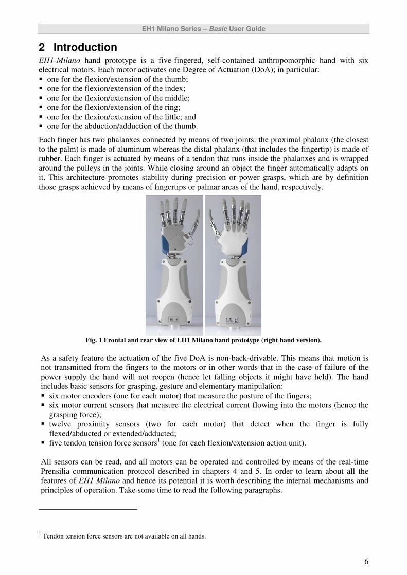
Each finger has two phalanxes connected by means of two joints: the proximal phalanx (the closest
to the palm) is made of aluminum whereas the distal phalanx (that includes the fingertip) is made of
rubber. Each finger is actuated by means of a tendon that runs inside the phalanxes and is wrapped
around the pulleys in the joints. While closing around an object the finger automatically adapts on
it. This architecture promotes stability during precision or power grasps, which are by definition
those grasps achieved by means of fingertips or palmar areas of the hand, respectively.
Fig. 1 Frontal and rear view of EH1 Milano hand prototype (right hand version).
As a safety feature the actuation of the five DoA is non-back-drivable. This means that motion is
not transmitted from the fingers to the motors or in other words that in the case of failure of the
power supply the hand will not reopen (hence let falling objects it might have held). The hand
includes basic sensors for grasping, gesture and elementary manipulation:
� six motor encoders (one for each motor) that measure the posture of the fingers;
� six motor current sensors that measure the electrical current flowing into the motors (hence the
grasping force);
� twelve proximity sensors (two for each motor) that detect when the finger is fully
flexed/abducted or extended/adducted;
� five tendon tension force sensors1 (one for each flexion/extension action unit).
All sensors can be read, and all motors can be operated and controlled by means of the real-time
Prensilia communication protocol described in chapters 4 and 5. In order to learn about all the
features of EH1 Milano and hence its potential it is worth describing the internal mechanisms and
principles of operation. Take some time to read the following paragraphs.
1 Tendon tension force sensors are not available on all hands.
EH1 Milano Series – Basic User Guide
7
2.1 Mechanisms overview
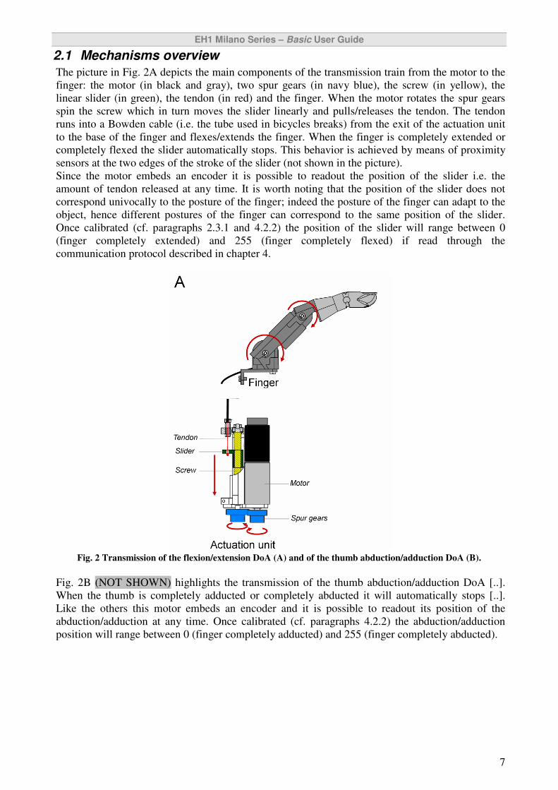
The picture in Fig. 2A depicts the main components of the transmission train from the motor to the
finger: the motor (in black and gray), two spur gears (in navy blue), the screw (in yellow), the
linear slider (in green), the tendon (in red) and the finger. When the motor rotates the spur gears
spin the screw which in turn moves the slider linearly and pulls/releases the tendon. The tendon
runs into a Bowden cable (i.e. the tube used in bicycles breaks) from the exit of the actuation unit
to the base of the finger and flexes/extends the finger. When the finger is completely extended or
completely flexed the slider automatically stops. This behavior is achieved by means of proximity
sensors at the two edges of the stroke of the slider (not shown in the picture).
Since the motor embeds an encoder it is possible to readout the position of the slider i.e. the
amount of tendon released at any time. It is worth noting that the position of the slider does not
correspond univocally to the posture of the finger; indeed the posture of the finger can adapt to the
object, hence different postures of the finger can correspond to the same position of the slider.
Once calibrated (cf. paragraphs 2.3.1 and 4.2.2) the position of the slider will range between 0
(finger completely extended) and 255 (finger completely flexed) if read through the
communication protocol described in chapter 4.
Fig. 2 Transmission of the flexion/extension DoA (A) and of the thumb abduction/adduction DoA (B).
Fig. 2B (NOT SHOWN) highlights the transmission of the thumb abduction/adduction DoA [..].
When the thumb is completely adducted or completely abducted it will automatically stops [..].
Like the others this motor embeds an encoder and it is possible to readout its position of the
abduction/adduction at any time. Once calibrated (cf. paragraphs 4.2.2) the abduction/adduction
position will range between 0 (finger completely adducted) and 255 (finger completely abducted).
EH1 Milano Series – Basic User Guide
8
2.2 Sensory system overview
EH1 Milano integrates: 6 motor rotary encoders for position measurement (one for each DoA), 6
motor current sensors, 5 tendon force tension sensors (one for each flexion/extension DoA)2, and 12
proximity sensors (two for each DoA). Encoders and current sensors, and/or tendon tension sensors
(if present) are used for position and force control during automatic grasps (cf. paragraph 2.3.2).
2.2.1 Motor rotary encoders
A rotary encoder, also called a shaft encoder, is an electro-mechanical device that converts the
angular position or motion of a shaft (e.g. the shaft of a motor) to a digital code. There are two main
types: absolute and incremental (relative) encoders. Incremental encoders are embedded in each of
the five motors of EH1 Milano; these provide information about the motion of the motor shaft,
which is processed by the internal controller into position information.
In EH1 Milano position information can be read in two ways: raw (or incremental) position and
calibrated (or absolute) position. Raw position represents the reading from the incremental encoder
without further processing; raw position is encoded in 17 bits. This means that the raw position
could range between 0 and 131071 (unsigned). Raw position is relative to the start position (i.e. 0)
which is the position of the motor/finger when the hand is switched ON. Calibrated position
represents a processed information which is computed by the internal controller after the calibration
procedure (cf. paragraphs 2.3.1 and 4.2.2). Calibrated position is encoded by 8 bits and ranges
between 0 (finger completely extended / thumb completely adducted) and 255 (finger completely
flexed / thumb completely abducted). The calibrated position resolution is hence around 0.78 deg.
Commands for reading raw position or calibrated position are described in chapter 4.
2.2.2 Motor current sensors
Motor current, IM, is measured using a high side measurement current shunt monitor (Texas
Instruments) and acquired by a 10 bit AD converter. The digital reading ranges between 0 and 1023
and respects the following law:
IM |flexion ≈ IM ⋅ 901
IM |adduction ≈ IM ⋅ 1230
For the flexion/extension or for the adduction/abduction DoA, respectively. The nominal motor
current resolution is around 1.1mA for the flexion/extension DoA and 0.81 mA for the
adduction/abduction DoA. Linearity is nominally achieved by the current shunt monitor in the range
10 and 1000 LSB. As an embedded safety feature, if the motor current overcomes the motor-
specific thermal limit current (0.41 A for thumb abduction/adduction, 0.81 A for finger
flexion/extension DoA) for longer than 1000 ms, the motor is automatically switched off and put in
STOP mode. Details on the motor current reading circuit are provided in paragraphs 8.1.1 and 8.1.3.
2.2.3 Tendon tension sensors2
Tendon tension sensors are designed and produced by Prensilia S.r.l.; these are based on micro-
machined cantilevers topped by semiconductor strain gauges that measure the force tension in the
tendon (proportional to the grasping force of the fingers). For the ring-little actuation unit, the
tendon tension sensor may be connected to one of the two fingers, by properly routing the tendon.
2.2.4 Proximity sensors
Hall effect digital proximity sensors (Allegro A3213 hall effect switches) are used to limit the
physical range of the DoA and to automatically stop the motors. When they are active the DoA is
either fully flexed (abducted) or extended (adducted).
2 Tendon tension force sensors are not available on all hands.

EH1 Milano Series – Basic User Guide
9
2.2.5 Sensor data resolution and encoding table
The following table resumes the resolution of the different sensors and the data encoding.
Type Binary encoding [#bits] LSB Resolution
Raw position 17 -
Calibrated position 8 0.78 deg
Motor current (flexion) 10 1.1 mA
Motor current (abduction) 10 0.81 mA
Tendon tension force 10 -
2.3 Control system overview
The scheme in Fig. 3 shows the control architecture of EH1 Milano. The embedded controller in the
hand is arranged in a hierarchical architecture consisting of 5 Low Level Motion Controllers
(LLMC) and one High Level Hand Controller (HLHC). Each Degree of Actuation (DoA) is directly
controlled by means of a LLMC that achieves position control, current control, tendon tension force
control3, and monitors motor current absorption (ensuring a long-life operation of the motor). All
LLMCs are controlled by the HLHC, that regulates overall hand operation, implements high level
functions (like automatic grasps) and acts as interface with the external world. Although EH1
Milano comes with the USB cable provided (cf. chapter 3), it uses a standard serial communication
bus (RS232, TTL levels) to communicate with the external world and internally (HLHC-LLMC
bus).
EH1 Milano presents two layers of non-volatile memory (E2PROM). The HLHC memorizes
automatic grasp features (preshaping postures and force levels, cf. paragraph 4.4), whereas each
LLMCs memorizes PID parameters (Kp, Ki, Kd) of the control algorithms (detailed in paragraph
8.2).
Fig. 3 EH1 Milano hierarchical control architecture
3.
The USB cable allows access to the sensors connected, to the functions implemented by the LLMCs
and to those implemented by the HLHC, through the communication protocol described in this
document (cf. chapters 4 and 5). In particular by communicating with the LLMC you can (for each
DoA/motor):
� Read the raw position (17 bits) / motor-current / tendon tension force value3;
3 Tendon tension force sensors are not available on all hands.
External World
HLHC
host PC
LLMC ..
BUS
• 6 encoders
• 12 proximity sensors
• 6 current sensors
• 5 tendon force tension
sensors
RS232 TTL
USB Cable
1
USB
Internal
RS
23
2
EH1 Milano
HL memory: automatic
grasps
LL memory: PID parameters LLMC 5
LLMC 0
LLMC 1
LLMC 2
EH1 Milano Series – Basic User Guide
10
� Set the speed / raw position (17 bits) / motor-current / tendon tension force3
of one DoA to a
desired value;
� Read / memorize (i.e. set in the internal memory) the PID parameters for the position / motor-
current / tendon tension force3 control loops;
� Read / memorize maximum motor-current or speed allowed by the DoA;
� Read the status of the DoA.
By communicating with the HLHC you can (among the others):
� Calibrate the hand;
� Read the calibrated position (8 bits) / motor-current / tendon tension force value3 for a specific
DoA;
� Set the speed / calibrated position (8 bits) / motor-current / tendon tension force3
of one DoA at a
desired value;
� Move the hand in a specific posture (i.e. move each DoA to a specific, desired position);
� Memorize automatic grasps;
� Launch automatic grasps.
The position of each DoA can be read in raw or in calibrated mode. The raw value (as it is read
from the encoder, i.e. in a 17 bit data format) can be requested to the LLMC; the calibrated value (8
bit data format, range 0-255 meaning DoA closed-open, respectively) can be read from the HLHC.
2.3.1 Calibration routines
EH1 Milano features two calibration routines that can be issued by sending the appropriate
commands over the communication bus; these are what is called the first calibration routine and
fast calibration routine.
The first calibration should be issued once in a while and most important every time there is a
change of the mechanics of the hand: this could be the case when a tendon is replaced, or the limits
of the abduction/adduction DoA are manually moved (cf. paragraph 8.4). Indeed, the first
calibration routine serves to map the open/close positions of the DoA to the position values of 0
and 255, respectively, and hence to readout consistent calibrated position values (as defined in
section 2.2.1, page 8). Once issued every DoA fully closes and opens so that the raw position from
the encoders is processed and memorized in the HLHC memory in order to map to the 0-255 range.
The fast calibration, as the name recalls, is a quicker routine: all DoA simply open and their
position is mapped to 0 (zero). For correct operation of the HLHC functions of the hand (e.g.
automatic grasps) the fast calibration should be the first command issued once the hand is switched
ON. The fast calibration will work properly only if a first calibration was issued at any time before
that moment. Although not strictly required the calibration routines can be issued at any time
without causing problems.
EH1 Milano Series – Basic User Guide
11
2.3.2 Automatic grasps
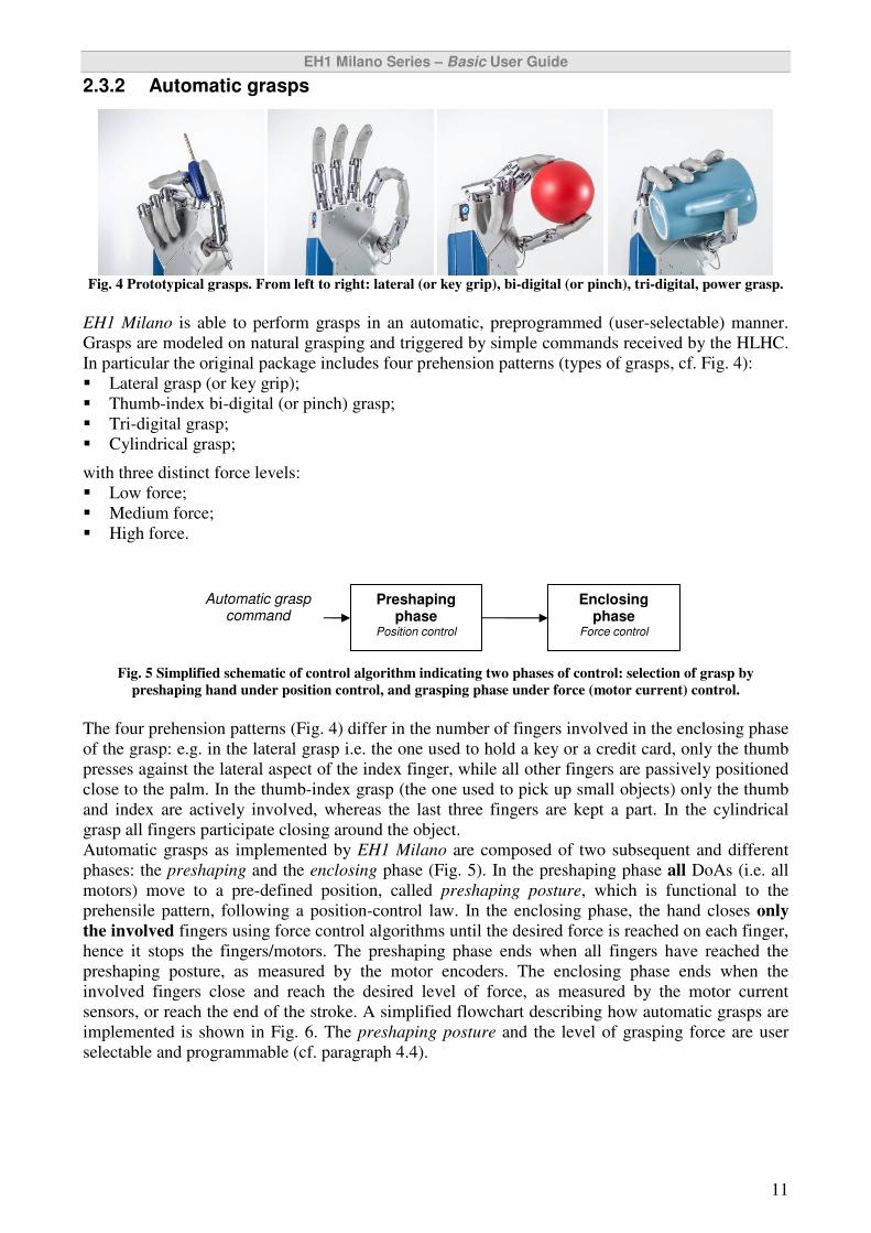
Fig. 4 Prototypical grasps. From left to right: lateral (or key grip), bi-digital (or pinch), tri-digital, power grasp.
EH1 Milano is able to perform grasps in an automatic, preprogrammed (user-selectable) manner.
Grasps are modeled on natural grasping and triggered by simple commands received by the HLHC.
In particular the original package includes four prehension patterns (types of grasps, cf. Fig. 4):
� Lateral grasp (or key grip);
� Thumb-index bi-digital (or pinch) grasp;
� Tri-digital grasp;
� Cylindrical grasp;
with three distinct force levels:
� Low force;
� Medium force;
� High force.
Fig. 5 Simplified schematic of control algorithm indicating two phases of control: selection of grasp by
preshaping hand under position control, and grasping phase under force (motor current) control.
The four prehension patterns (Fig. 4) differ in the number of fingers involved in the enclosing phase
of the grasp: e.g. in the lateral grasp i.e. the one used to hold a key or a credit card, only the thumb
presses against the lateral aspect of the index finger, while all other fingers are passively positioned
close to the palm. In the thumb-index grasp (the one used to pick up small objects) only the thumb
and index are actively involved, whereas the last three fingers are kept a part. In the cylindrical
grasp all fingers participate closing around the object.
Automatic grasps as implemented by EH1 Milano are composed of two subsequent and different
phases: the preshaping and the enclosing phase (Fig. 5). In the preshaping phase all DoAs (i.e. all
motors) move to a pre-defined position, called preshaping posture, which is functional to the
prehensile pattern, following a position-control law. In the enclosing phase, the hand closes only
the involved fingers using force control algorithms until the desired force is reached on each finger,
hence it stops the fingers/motors. The preshaping phase ends when all fingers have reached the
preshaping posture, as measured by the motor encoders. The enclosing phase ends when the
involved fingers close and reach the desired level of force, as measured by the motor current
sensors, or reach the end of the stroke. A simplified flowchart describing how automatic grasps are
implemented is shown in Fig. 6. The preshaping posture and the level of grasping force are user
selectable and programmable (cf. paragraph 4.4).
Automatic grasp command
Preshaping phase
Position control
Enclosing phase
Force control

EH1 Milano Series – Basic User Guide
12
Fig. 6 Simplified flow-chart of automatic grasps.
Automatic grasps will not work if the hand is not calibrated.
2.4 Communication protocol overview
EH1-Milano receives commands from a host Personal Computer (PC) (or other controlling system)
in the form of sequences of serial communication bytes called packets. The communication is
achieved over a RS232 serial bus, which is accessible by means of the USB cable provided (see
chapter 3). The HLHC in the hand buffers the incoming command stream and will only take an
action once the entire packet has been received and the closing byte (where present) has been
verified as correct. Non-existing packets will be ignored, whereas incomplete packets will make
EH1 Milano wait for the completion of the packet. The command buffer will, however, be cleared
whenever the hand is powered off/on.
Automatic grasp command
(e.g. low-force cylindrical)
Preshaping phase
Position control –
all DoAs
Enclosing phase
Force control – Involved DoAs
all fingers reached
preshaping posture?
yes
no
involved fingers reached desired force?
yes
no
involved fingers reached
complete closure?
Automatic grasp ends
yes
no

EH1 Milano Series – Basic User Guide
13
2.4.1 RS232 (COM port) communication settings
The RS232 protocol settings required for communicating with EH1 Milano are listed in Table 1.
The same settings are used in the internal communication bus between HLHC and LLMCs.
RS232 Asynchronous Communication (No handshake control).
Serial wires used TX, RX, GND
Baud Rate 115200 baud/sec
No. Bits 8
Stop bits 1
Parity None
Voltage levels TTL (0 +5V)
Table 1: LLMC communication protocol requirements.
2.4.2 Addresses of the motors
When communicating with EH1 Milano, each motor (or LLMC) is identified by a fixed Motor
Address (MA), as follows:
Motor Address (MA) DoA
0 Thumb abduction/adduction
1 Thumb flexion/extension
2 Index flexion/extension
3 Middle flexion/extension
4 Ring flexion/extension
5 Little flexion/extension
An easy way to remember addresses is the following: thumb is the first finger, hence address is 1;
index is the second finger (2), middle is the third (3), ring is the fourth (4) and little is the fifth (5).
2.4.3 STATUS byte and control modes
Condensed information regarding the internal status of a specific LLMC can be obtained by
requesting its STATUS byte, over the communication bus. Specifically the STATUS byte informs:
� about the type of control algorithm currently being implemented by the LLMC, which could be:
a. STOP mode � the motor is still and not in control;
b. PWM/Speed mode � the motor is driven with fixed PWM, i.e. in feed-forward
speed control;
c. Position mode � the motor is in position control;
d. Tension mode � the flexion/extension motor (MA: 1÷5) is running in tendon force
tension control;
e. Current mode � the motor is closing with a at specific motor current value (motor
torque control);
f. Current/Position mode � the motor is closing with a at specific motor current value
(motor torque control) until it will stop moving; then it will break;
g. COM ERROR � internal bus (HLHC-LLMCs) communication error;
� if the desired control target was reached or not;
� if the open proximity sensor is ON (finger extended, thumb adducted);
� if the close proximity sensor is ON (finger flexed, thumb abducted);
� if the motor current overcame the maximum current allowed by the user (c.f. paragraph 8.1.4) or
the thermal limit (paragraph 2.2.2, page 8).
EH1 Milano Series – Basic User Guide
14
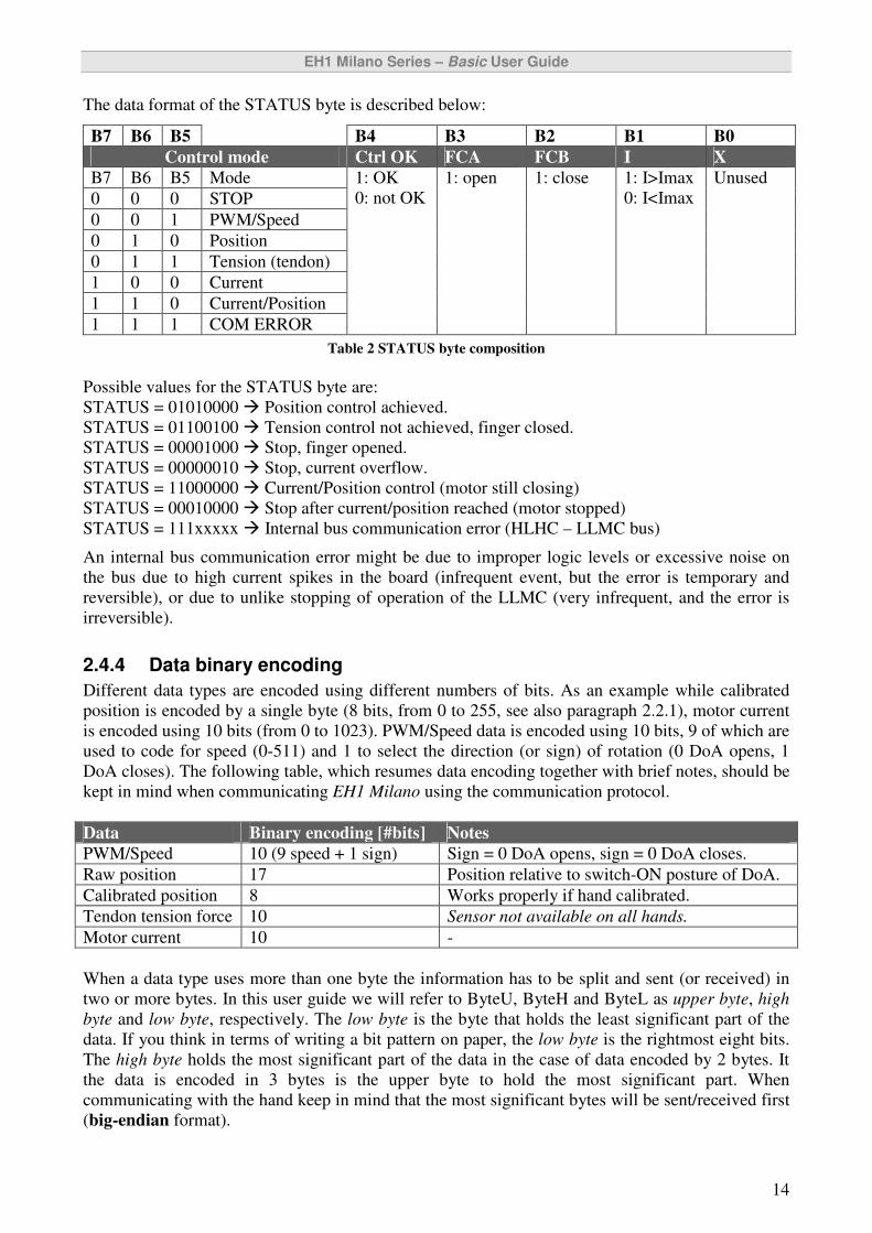
The data format of the STATUS byte is described below:
B7 B6 B5 B4 B3 B2 B1 B0
Control mode Ctrl OK FCA FCB I X
B7 B6 B5 Mode
0 0 0 STOP
0 0 1 PWM/Speed
0 1 0 Position
0 1 1 Tension (tendon)
1 0 0 Current
1 1 0 Current/Position
1 1 1 COM ERROR
1: OK
0: not OK
1: open 1: close 1: I>Imax
0: I<Imax
Unused
Table 2 STATUS byte composition
Possible values for the STATUS byte are:
STATUS = 01010000 � Position control achieved.
STATUS = 01100100 � Tension control not achieved, finger closed.
STATUS = 00001000 � Stop, finger opened.
STATUS = 00000010 � Stop, current overflow.
STATUS = 11000000 � Current/Position control (motor still closing)
STATUS = 00010000 � Stop after current/position reached (motor stopped)
STATUS = 111xxxxx � Internal bus communication error (HLHC – LLMC bus)
An internal bus communication error might be due to improper logic levels or excessive noise on
the bus due to high current spikes in the board (infrequent event, but the error is temporary and
reversible), or due to unlike stopping of operation of the LLMC (very infrequent, and the error is
irreversible).
2.4.4 Data binary encoding
Different data types are encoded using different numbers of bits. As an example while calibrated
position is encoded by a single byte (8 bits, from 0 to 255, see also paragraph 2.2.1), motor current
is encoded using 10 bits (from 0 to 1023). PWM/Speed data is encoded using 10 bits, 9 of which are
used to code for speed (0-511) and 1 to select the direction (or sign) of rotation (0 DoA opens, 1
DoA closes). The following table, which resumes data encoding together with brief notes, should be
kept in mind when communicating EH1 Milano using the communication protocol.
Data Binary encoding [#bits] Notes
PWM/Speed 10 (9 speed + 1 sign) Sign = 0 DoA opens, sign = 0 DoA closes.
Raw position 17 Position relative to switch-ON posture of DoA.
Calibrated position 8 Works properly if hand calibrated.
Tendon tension force 10 Sensor not available on all hands.
Motor current 10 -
When a data type uses more than one byte the information has to be split and sent (or received) in
two or more bytes. In this user guide we will refer to ByteU, ByteH and ByteL as upper byte, high
byte and low byte, respectively. The low byte is the byte that holds the least significant part of the
data. If you think in terms of writing a bit pattern on paper, the low byte is the rightmost eight bits.
The high byte holds the most significant part of the data in the case of data encoded by 2 bytes. It
the data is encoded in 3 bytes is the upper byte to hold the most significant part. When
communicating with the hand keep in mind that the most significant bytes will be sent/received first
(big-endian format).
EH1 Milano Series – Basic User Guide
15
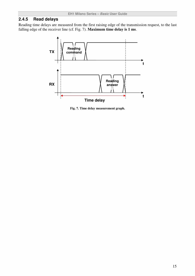
2.4.5 Read delays
Reading time delays are measured from the first raising edge of the transmission request, to the last
falling edge of the receiver line (cf. Fig. 7). Maximum time delay is 1 ms.
Fig. 7. Time delay measurement graph.
Reading command TX
t
RX
t
Reading answer
Time delay
EH1 Milano Series – Basic User Guide
16
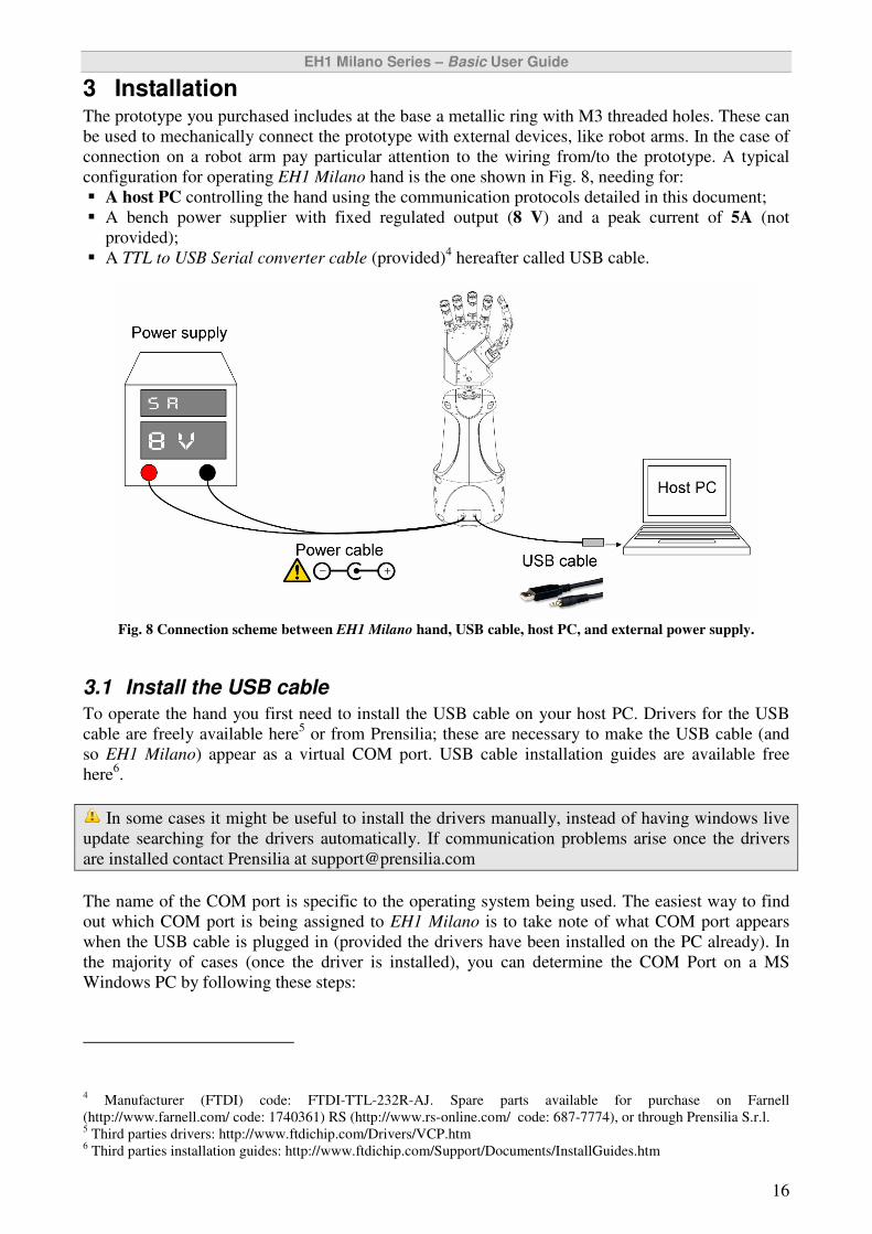
3 Installation The prototype you purchased includes at the base a metallic ring with M3 threaded holes. These can
be used to mechanically connect the prototype with external devices, like robot arms. In the case of
connection on a robot arm pay particular attention to the wiring from/to the prototype. A typical
configuration for operating EH1 Milano hand is the one shown in Fig. 8, needing for:
� A host PC controlling the hand using the communication protocols detailed in this document;
� A bench power supplier with fixed regulated output (8 V) and a peak current of 5A (not
provided);
� A TTL to USB Serial converter cable (provided)4 hereafter called USB cable.
Fig. 8 Connection scheme between EH1 Milano hand, USB cable, host PC, and external power supply.
3.1 Install the USB cable
To operate the hand you first need to install the USB cable on your host PC. Drivers for the USB
cable are freely available here5 or from Prensilia; these are necessary to make the USB cable (and
so EH1 Milano) appear as a virtual COM port. USB cable installation guides are available free
here6.
In some cases it might be useful to install the drivers manually, instead of having windows live
update searching for the drivers automatically. If communication problems arise once the drivers
are installed contact Prensilia at [email protected]
The name of the COM port is specific to the operating system being used. The easiest way to find
out which COM port is being assigned to EH1 Milano is to take note of what COM port appears
when the USB cable is plugged in (provided the drivers have been installed on the PC already). In
the majority of cases (once the driver is installed), you can determine the COM Port on a MS
Windows PC by following these steps:
4 Manufacturer (FTDI) code: FTDI-TTL-232R-AJ. Spare parts available for purchase on Farnell
(http://www.farnell.com/ code: 1740361) RS (http://www.rs-online.com/ code: 687-7774), or through Prensilia S.r.l. 5 Third parties drivers: http://www.ftdichip.com/Drivers/VCP.htm
6 Third parties installation guides: http://www.ftdichip.com/Support/Documents/InstallGuides.htm

EH1 Milano Series – Basic User Guide
17
1) Open Device Manager: Click: Start � Control Panel � Performance and Maintenance �
System � Hardware � Device Manager
2) In the Device Manager list, look in Ports and find the COM Port, which was created by the
USB driver. i.e.___ USB Serial Port___ (COM #).
3.2 Connect the cables and power-ON the hand
To operate EH1 Milano once the USB cable drivers are successfully installed
1) Connect the USB cable to the host PC;
2) Connect the USB cable to the 3.5mm stereo Jack connector on EH1 Milano;
3) Connect the black/red cable (provided) to an external power supply with regulated voltage
output (+8V and GND), and to the power connector on EH1 Milano;
4) Switch-ON the power supply.
5) Once switched-ON the hand will start a greeting routine: all DoA will open, then close and
reopen again. During this routine the hand calibrates itself.
6) The hand is now operative and ready to communicate with the host PC!
The USB cable and the power supply cable can be connected in any order. However, if the USB
cable is connected after the hand is switched-ON, some spurious signals could reach the hand
through the serial port while physically connecting the plug. This could potentially issue a
command or part of it and could leave in the host input queue spurious bytes as well, causing
communication problems (if not correctly handled). It is suggested to switch-ON the hand after
plugging in the USB connection.
Do not touch the metallic parts of the connectors (which are both connected to the system
ground) once plugged in. The hand is a Static Sensitive Device!
EH1 Milano Series – Basic User Guide
18
4 HLHC commands The High Level Hand Controller of EH1 Milano hand is accessible through the USB cable
(provided) by means of variable length packets acting as recognized commands. Commands are
divided into:
� Single DoA commands: for simple operation regarding one motor or sensor, such as finger
movement, finger position control, reading of one sensor, etc.;
� Status/Calibrate commands: to obtain fingers/DoAs status and issue calibration routines;
� Whole hand commands: to automatically obtain complex operations related to the whole hand,
such as automatic grasps;
� Memory commands: to store in the HLHC settings for the automatic grasps.
4.1 Single DoA commands
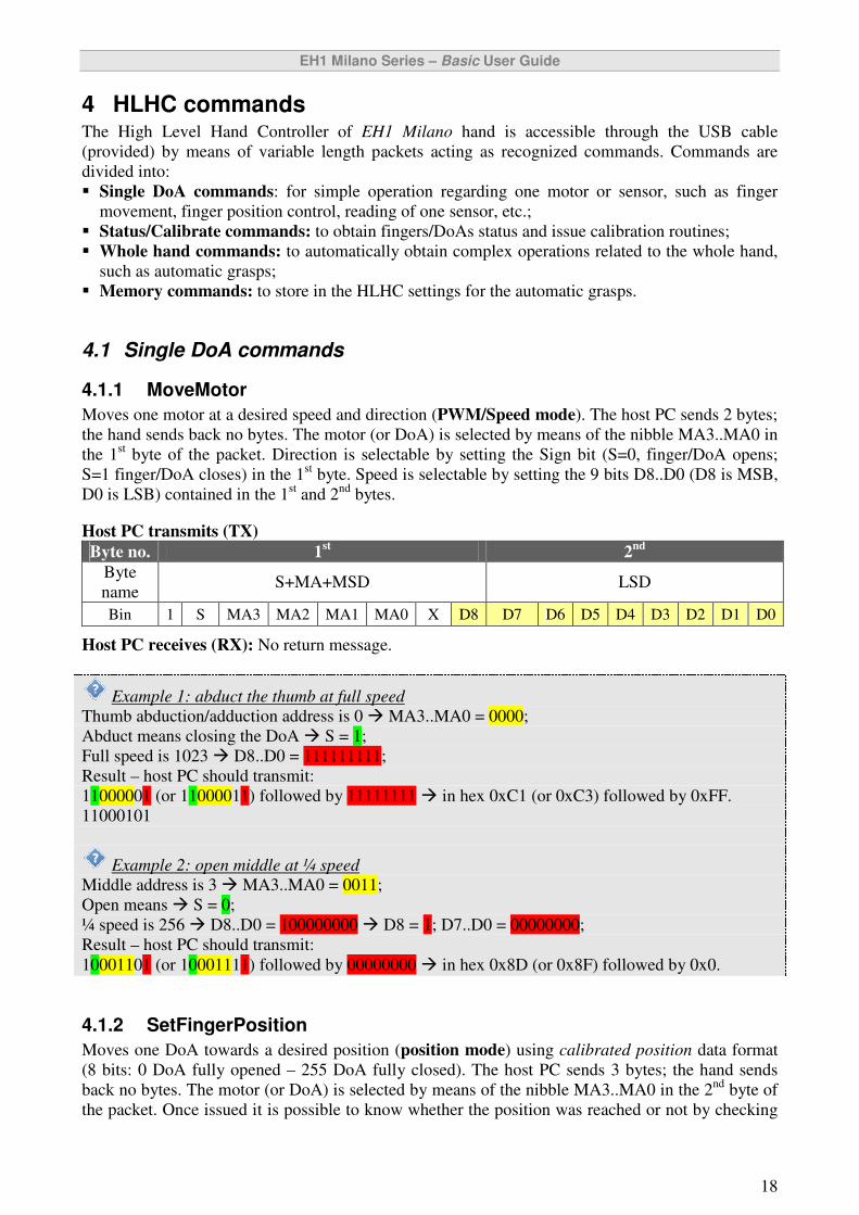
4.1.1 MoveMotor
Moves one motor at a desired speed and direction (PWM/Speed mode). The host PC sends 2 bytes;
the hand sends back no bytes. The motor (or DoA) is selected by means of the nibble MA3..MA0 in
the 1st byte of the packet. Direction is selectable by setting the Sign bit (S=0, finger/DoA opens;
S=1 finger/DoA closes) in the 1st byte. Speed is selectable by setting the 9 bits D8..D0 (D8 is MSB,
D0 is LSB) contained in the 1st and 2
nd bytes.
Host PC transmits (TX)
Byte no. 1st 2
nd
Byte
name S+MA+MSD LSD
Bin 1 S MA3 MA2 MA1 MA0 X D8 D7 D6 D5 D4 D3 D2 D1 D0
Host PC receives (RX): No return message.
Example 1: abduct the thumb at full speed
Thumb abduction/adduction address is 0 � MA3..MA0 = 0000;
Abduct means closing the DoA � S = 1;
Full speed is 1023 � D8..D0 = 111111111;
Result – host PC should transmit:
11000001 (or 11000011) followed by 11111111 � in hex 0xC1 (or 0xC3) followed by 0xFF.
11000101
Example 2: open middle at ¼ speed
Middle address is 3 � MA3..MA0 = 0011;
Open means � S = 0;
¼ speed is 256 � D8..D0 = 100000000 � D8 = 1; D7..D0 = 00000000;
Result – host PC should transmit:
10001101 (or 10001111) followed by 00000000 � in hex 0x8D (or 0x8F) followed by 0x0.
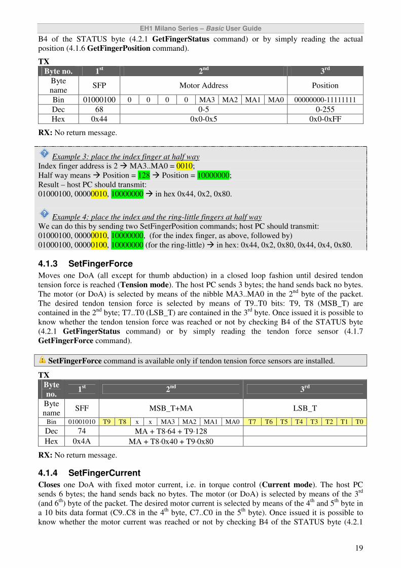
4.1.2 SetFingerPosition
Moves one DoA towards a desired position (position mode) using calibrated position data format
(8 bits: 0 DoA fully opened – 255 DoA fully closed). The host PC sends 3 bytes; the hand sends
back no bytes. The motor (or DoA) is selected by means of the nibble MA3..MA0 in the 2nd
byte of
the packet. Once issued it is possible to know whether the position was reached or not by checking
EH1 Milano Series – Basic User Guide
19
B4 of the STATUS byte (4.2.1 GetFingerStatus command) or by simply reading the actual
position (4.1.6 GetFingerPosition command).
TX
Byte no. 1st 2
nd 3
rd
Byte
name SFP Motor Address Position
Bin 01000100 0 0 0 0 MA3 MA2 MA1 MA0 00000000-11111111
Dec 68 0-5 0-255
Hex 0x44 0x0-0x5 0x0-0xFF
RX: No return message.
Example 3: place the index finger at half way
Index finger address is 2 � MA3..MA0 = 0010;
Half way means � Position = 128 � Position = 10000000;
Result – host PC should transmit:
01000100, 00000010, 10000000 � in hex 0x44, 0x2, 0x80.
Example 4: place the index and the ring-little fingers at half way
We can do this by sending two SetFingerPosition commands; host PC should transmit:
01000100, 00000010, 10000000, (for the index finger, as above, followed by)
01000100, 00000100, 10000000 (for the ring-little) � in hex: 0x44, 0x2, 0x80, 0x44, 0x4, 0x80.
4.1.3 SetFingerForce
Moves one DoA (all except for thumb abduction) in a closed loop fashion until desired tendon
tension force is reached (Tension mode). The host PC sends 3 bytes; the hand sends back no bytes.
The motor (or DoA) is selected by means of the nibble MA3..MA0 in the 2nd
byte of the packet.
The desired tendon tension force is selected by means of T9..T0 bits: T9, T8 (MSB_T) are
contained in the 2nd
byte; T7..T0 (LSB_T) are contained in the 3rd
byte. Once issued it is possible to
know whether the tendon tension force was reached or not by checking B4 of the STATUS byte
(4.2.1 GetFingerStatus command) or by simply reading the tendon force sensor (4.1.7
GetFingerForce command).
SetFingerForce command is available only if tendon tension force sensors are installed.
TX
Byte
no. 1
st 2
nd 3
rd
Byte
name SFF MSB_T+MA LSB_T
Bin 01001010 T9 T8 x x MA3 MA2 MA1 MA0 T7 T6 T5 T4 T3 T2 T1 T0
Dec 74 MA + T8⋅64 + T9⋅128
Hex 0x4A MA + T8⋅0x40 + T9⋅0x80
RX: No return message.
4.1.4 SetFingerCurrent
Closes one DoA with fixed motor current, i.e. in torque control (Current mode). The host PC
sends 6 bytes; the hand sends back no bytes. The motor (or DoA) is selected by means of the 3rd
(and 6th
) byte of the packet. The desired motor current is selected by means of the 4th
and 5th
byte in
a 10 bits data format (C9..C8 in the 4th
byte, C7..C0 in the 5th
byte). Once issued it is possible to
know whether the motor current was reached or not by checking B4 of the STATUS byte (4.2.1
EH1 Milano Series – Basic User Guide
20
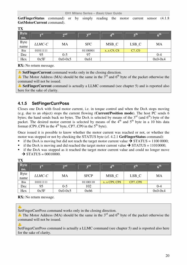
GetFingerStatus command) or by simply reading the motor current sensor (4.1.8
GetMotorCurrent command).
TX
Byte
no. 1
st 2
nd 3
rd 4
th 5
th 6
th
Byte
name LLMC-C MA SFC MSB_C LSB_C MA
Bin 01011111 01100001 x..x C9, C8 C7..C0
Dec 95 0-5 97 0-4
Hex 0x5F 0x0-0x5 0x61 0x0-0x4
RX: No return message.
SetFingerCurrent command works only in the closing direction.
The Motor Address (MA) should be the same in the 3rd
and 6th
byte of the packet otherwise the
command will not be issued.
SetFingerCurrent command is actually a LLMC command (see chapter 5) and is reported also
here for the sake of clarity.
4.1.5 SetFingerCurrPoss
Closes one DoA with fixed motor current, i.e. in torque control and when the DoA stops moving
(e.g. due to an object) stops the current flowing (Current/Position mode). The host PC sends 6
bytes; the hand sends back no bytes. The DoA is selected by means of the 3rd
(and 6th
) byte of the
packet. The desired motor current is selected by means of the 4th
and 5th
byte in a 10 bits data
format (CP9..CP8 in the 4th
byte, CP7..CP0 in the 5th
byte).
Once issued it is possible to know whether the motor current was reached or not, or whether the
motor was stopped or not by checking the STATUS byte (cf. 4.2.1 GetFingerStatus command):
� if the DoA is moving but did not reach the target motor current value ���� STATUS = 1100 0000;
� if the DoA is moving and did reached the target motor current value ���� STATUS = 11010000;
� if the DoA was stopped as it reached the target motor current value and could no longer move
���� STATUS = 00010000.
TX
Byte
no. 1
st 2
nd 3
rd 4
th 5
th 6
th
Byte
name LLMC-C MA SFCP MSB_C LSB_C MA
Bin 01011111 01100110 x..x CP9, CP8 CP7..CP0
Dec 95 0-5 102 0-4
Hex 0x5F 0x0-0x5 0x66 0x0-0x4
RX: No return message.
SetFingerCurrPoss command works only in the closing direction.
The Motor Address (MA) should be the same in the 3rd
and 6th
byte of the packet otherwise the
command will not be issued.
SetFingerCurrPoss command is actually a LLMC command (see chapter 5) and is reported also here
for the sake of clarity.
EH1 Milano Series – Basic User Guide
21
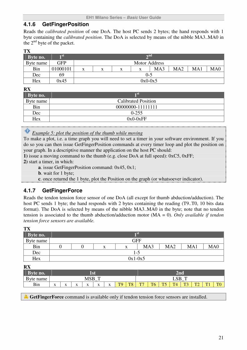
4.1.6 GetFingerPosition
Reads the calibrated position of one DoA. The host PC sends 2 bytes; the hand responds with 1
byte containing the calibrated position. The DoA is selected by means of the nibble MA3..MA0 in
the 2nd
byte of the packet.
TX
Byte no. 1st 2
nd
Byte name GFP Motor Address
Bin 01000101 x x x x MA3 MA2 MA1 MA0
Dec 69 0-5
Hex 0x45 0x0-0x5
RX
Byte no. 1st
Byte name Calibrated Position
Bin 00000000-11111111
Dec 0-255
Hex 0x0-0xFF
Example 5: plot the position of the thumb while moving
To make a plot, i.e. a time graph you will need to set a timer in your software environment. If you
do so you can then issue GetFingerPosition commands at every timer loop and plot the position on
your graph. In a descriptive manner the application on the host PC should:
1) issue a moving command to the thumb (e.g. close DoA at full speed): 0xC5, 0xFF;
2) start a timer, in which:
a. issue GetFingerPosition command: 0x45, 0x1;
b. wait for 1 byte;
c. once returnd the 1 byte, plot the Position on the graph (or whatsoever indicator).
4.1.7 GetFingerForce
Reads the tendon tension force sensor of one DoA (all except for thumb abduction/adduction). The
host PC sends 1 byte; the hand responds with 2 bytes containing the reading (T9..T0, 10 bits data
format). The DoA is selected by means of the nibble MA3..MA0 in the byte; note that no tendon
tension is associated to the thumb abduction/adduction motor (MA = 0). Only available if tendon
tension force sensors are available.
TX
Byte no. 1st
Byte name GFF
Bin 0 0 x x MA3 MA2 MA1 MA0
Dec 1-5
Hex 0x1-0x5
RX
Byte no. 1st 2nd
Byte name MSB_T LSB_T Bin x x x x x x T9 T8 T7 T6 T5 T4 T3 T2 T1 T0
GetFingerForce command is available only if tendon tension force sensors are installed.
EH1 Milano Series – Basic User Guide
22
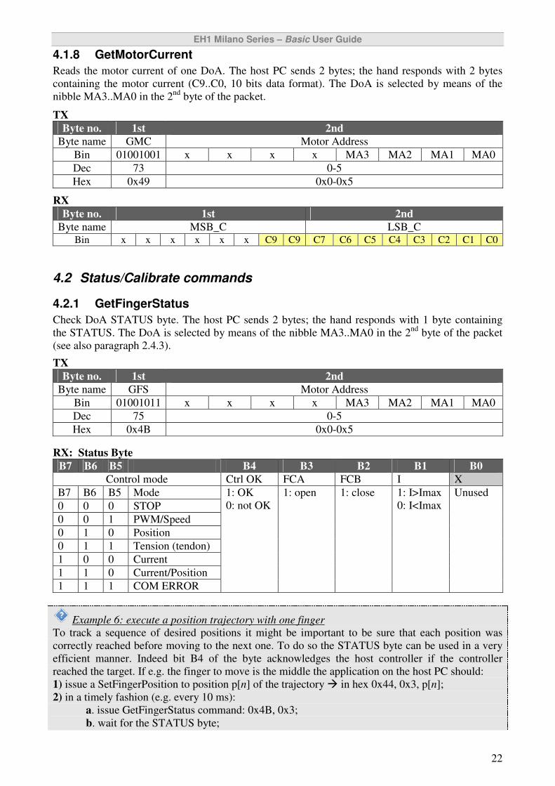
4.1.8 GetMotorCurrent
Reads the motor current of one DoA. The host PC sends 2 bytes; the hand responds with 2 bytes
containing the motor current (C9..C0, 10 bits data format). The DoA is selected by means of the
nibble MA3..MA0 in the 2nd
byte of the packet.
TX
Byte no. 1st 2nd
Byte name GMC Motor Address
Bin 01001001 x x x x MA3 MA2 MA1 MA0
Dec 73 0-5
Hex 0x49 0x0-0x5
RX
Byte no. 1st 2nd
Byte name MSB_C LSB_C Bin x x x x x x C9 C9 C7 C6 C5 C4 C3 C2 C1 C0
4.2 Status/Calibrate commands
4.2.1 GetFingerStatus
Check DoA STATUS byte. The host PC sends 2 bytes; the hand responds with 1 byte containing
the STATUS. The DoA is selected by means of the nibble MA3..MA0 in the 2nd
byte of the packet
(see also paragraph 2.4.3).
TX
Byte no. 1st 2nd
Byte name GFS Motor Address
Bin 01001011 x x x x MA3 MA2 MA1 MA0
Dec 75 0-5
Hex 0x4B 0x0-0x5
RX: Status Byte
B7 B6 B5 B4 B3 B2 B1 B0
Control mode Ctrl OK FCA FCB I X
B7 B6 B5 Mode
0 0 0 STOP
0 0 1 PWM/Speed
0 1 0 Position
0 1 1 Tension (tendon)
1 0 0 Current
1 1 0 Current/Position
1 1 1 COM ERROR
1: OK
0: not OK
1: open 1: close 1: I>Imax
0: I<Imax
Unused
Example 6: execute a position trajectory with one finger
To track a sequence of desired positions it might be important to be sure that each position was
correctly reached before moving to the next one. To do so the STATUS byte can be used in a very
efficient manner. Indeed bit B4 of the byte acknowledges the host controller if the controller
reached the target. If e.g. the finger to move is the middle the application on the host PC should:
1) issue a SetFingerPosition to position p[n] of the trajectory � in hex 0x44, 0x3, p[n];
2) in a timely fashion (e.g. every 10 ms):
a. issue GetFingerStatus command: 0x4B, 0x3;
b. wait for the STATUS byte;
EH1 Milano Series – Basic User Guide
23
c. check if B4 � in c language: (STATUS>>4)&0x1
d. if B4 = 1 the position is reached, hence set next position (n=n+1) and go to 1);
e. if B4 = 0 the position is not reached, hence go to a.
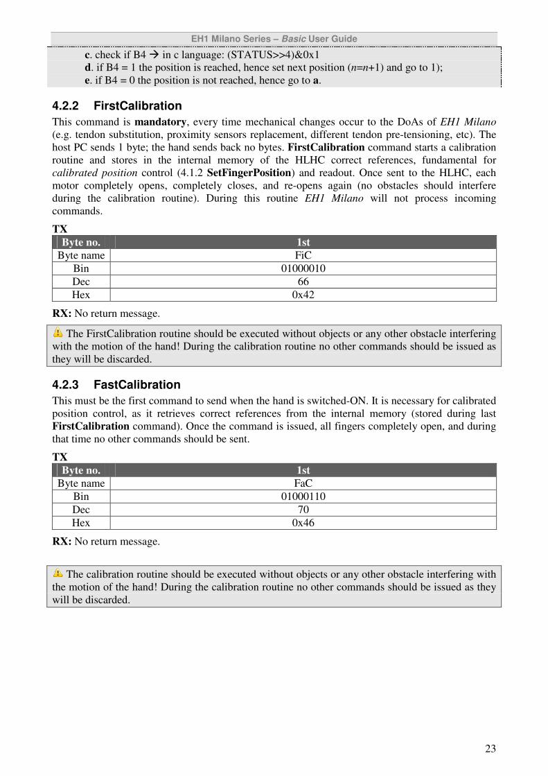
4.2.2 FirstCalibration
This command is mandatory, every time mechanical changes occur to the DoAs of EH1 Milano
(e.g. tendon substitution, proximity sensors replacement, different tendon pre-tensioning, etc). The
host PC sends 1 byte; the hand sends back no bytes. FirstCalibration command starts a calibration
routine and stores in the internal memory of the HLHC correct references, fundamental for
calibrated position control (4.1.2 SetFingerPosition) and readout. Once sent to the HLHC, each
motor completely opens, completely closes, and re-opens again (no obstacles should interfere
during the calibration routine). During this routine EH1 Milano will not process incoming
commands.
TX
Byte no. 1st
Byte name FiC
Bin 01000010
Dec 66
Hex 0x42
RX: No return message.
The FirstCalibration routine should be executed without objects or any other obstacle interfering
with the motion of the hand! During the calibration routine no other commands should be issued as
they will be discarded.
4.2.3 FastCalibration
This must be the first command to send when the hand is switched-ON. It is necessary for calibrated
position control, as it retrieves correct references from the internal memory (stored during last
FirstCalibration command). Once the command is issued, all fingers completely open, and during
that time no other commands should be sent.
TX
Byte no. 1st
Byte name FaC
Bin 01000110
Dec 70
Hex 0x46
RX: No return message.
The calibration routine should be executed without objects or any other obstacle interfering with
the motion of the hand! During the calibration routine no other commands should be issued as they
will be discarded.
EH1 Milano Series – Basic User Guide
24
4.3 Whole hand commands
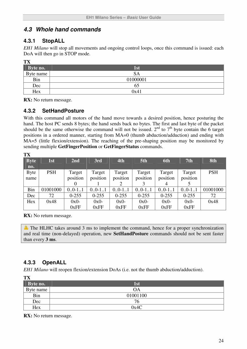
4.3.1 StopALL
EH1 Milano will stop all movements and ongoing control loops, once this command is issued: each
DoA will then go in STOP mode.
TX
Byte no. 1st
Byte name SA
Bin 01000001
Dec 65
Hex 0x41
RX: No return message.
4.3.2 SetHandPosture
With this command all motors of the hand move towards a desired position, hence posturing the
hand. The host PC sends 8 bytes; the hand sends back no bytes. The first and last byte of the packet
should be the same otherwise the command will not be issued. 2nd
to 7th
byte contain the 6 target
positions in a ordered manner, starting from MA=0 (thumb abduction/adduction) and ending with
MA=5 (little flexion/extension). The reaching of the pre-shaping position may be monitored by
sending multiple GetFingerPosition or GetFingerStatus commands.
TX
Byte
no.
1st 2nd 3rd 4th 5th 6th 7th 8th
Byte
name
PSH Target
position
0
Target
position
1
Target
position
2
Target
position
3
Target
position
4
Target
position
5
PSH
Bin 01001000 0..0-1..1 0..0-1..1 0..0-1..1 0..0-1..1 0..0-1..1 0..0-1..1 01001000
Dec 72 0-255 0-255 0-255 0-255 0-255 0-255 72
Hex 0x48 0x0-
0xFF
0x0-
0xFF
0x0-
0xFF
0x0-
0xFF
0x0-
0xFF
0x0-
0xFF
0x48
RX: No return message.
The HLHC takes around 3 ms to implement the command, hence for a proper synchronization
and real time (non-delayed) operation, new SetHandPosture commands should not be sent faster
than every 3 ms.
4.3.3 OpenALL
EH1 Milano will reopen flexion/extension DoAs (i.e. not the thumb abduction/adduction).
TX
Byte no. 1st
Byte name OA
Bin 01001100
Dec 76
Hex 0x4C
RX: No return message.
EH1 Milano Series – Basic User Guide
25
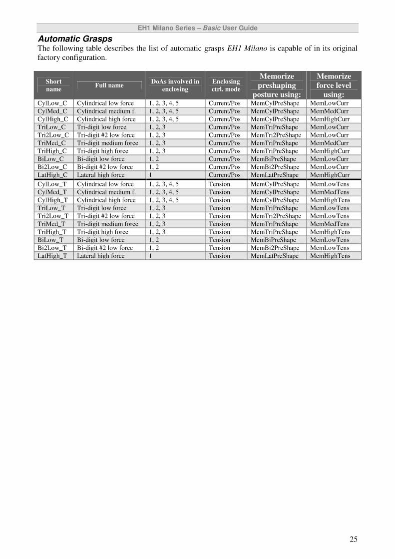
Automatic Grasps The following table describes the list of automatic grasps EH1 Milano is capable of in its original
factory configuration.
Short
name Full name
DoAs involved in
enclosing
Enclosing
ctrl. mode
Memorize
preshaping
posture using:
Memorize
force level
using: CylLow_C Cylindrical low force 1, 2, 3, 4, 5 Current/Pos MemCylPreShape MemLowCurr
CylMed_C Cylindrical medium f. 1, 2, 3, 4, 5 Current/Pos MemCylPreShape MemMedCurr
CylHigh_C Cylindrical high force 1, 2, 3, 4, 5 Current/Pos MemCylPreShape MemHighCurr
TriLow_C Tri-digit low force 1, 2, 3 Current/Pos MemTriPreShape MemLowCurr
Tri2Low_C Tri-digit #2 low force 1, 2, 3 Current/Pos MemTri2PreShape MemLowCurr
TriMed_C Tri-digit medium force 1, 2, 3 Current/Pos MemTriPreShape MemMedCurr
TriHigh_C Tri-digit high force 1, 2, 3 Current/Pos MemTriPreShape MemHighCurr
BiLow_C Bi-digit low force 1, 2 Current/Pos MemBiPreShape MemLowCurr
Bi2Low_C Bi-digit #2 low force 1, 2 Current/Pos MemBi2PreShape MemLowCurr
LatHigh_C Lateral high force 1 Current/Pos MemLatPreShape MemHighCurr
CylLow_T Cylindrical low force 1, 2, 3, 4, 5 Tension MemCylPreShape MemLowTens
CylMed_T Cylindrical medium f. 1, 2, 3, 4, 5 Tension MemCylPreShape MemMedTens
CylHigh_T Cylindrical high force 1, 2, 3, 4, 5 Tension MemCylPreShape MemHighTens
TriLow_T Tri-digit low force 1, 2, 3 Tension MemTriPreShape MemLowTens
Tri2Low_T Tri-digit #2 low force 1, 2, 3 Tension MemTri2PreShape MemLowTens
TriMed_T Tri-digit medium force 1, 2, 3 Tension MemTriPreShape MemMedTens
TriHigh_T Tri-digit high force 1, 2, 3 Tension MemTriPreShape MemHighTens
BiLow_T Bi-digit low force 1, 2 Tension MemBiPreShape MemLowTens
Bi2Low_T Bi-digit #2 low force 1, 2 Tension MemBi2PreShape MemLowTens
LatHigh_T Lateral high force 1 Tension MemLatPreShape MemHighTens
EH1 Milano Series – Basic User Guide
26
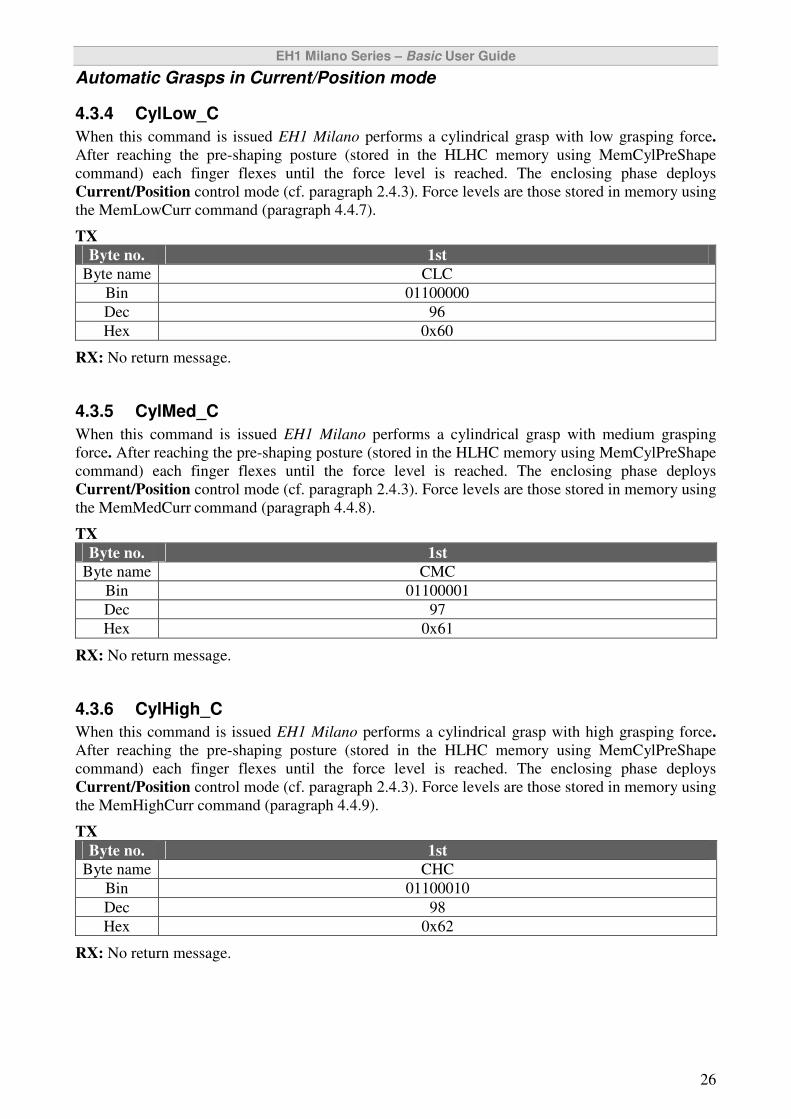
Automatic Grasps in Current/Position mode
4.3.4 CylLow_C
When this command is issued EH1 Milano performs a cylindrical grasp with low grasping force.
After reaching the pre-shaping posture (stored in the HLHC memory using MemCylPreShape
command) each finger flexes until the force level is reached. The enclosing phase deploys
Current/Position control mode (cf. paragraph 2.4.3). Force levels are those stored in memory using
the MemLowCurr command (paragraph 4.4.7).
TX
Byte no. 1st
Byte name CLC
Bin 01100000
Dec 96
Hex 0x60
RX: No return message.
4.3.5 CylMed_C
When this command is issued EH1 Milano performs a cylindrical grasp with medium grasping
force. After reaching the pre-shaping posture (stored in the HLHC memory using MemCylPreShape
command) each finger flexes until the force level is reached. The enclosing phase deploys
Current/Position control mode (cf. paragraph 2.4.3). Force levels are those stored in memory using
the MemMedCurr command (paragraph 4.4.8).
TX
Byte no. 1st
Byte name CMC
Bin 01100001
Dec 97
Hex 0x61
RX: No return message.
4.3.6 CylHigh_C
When this command is issued EH1 Milano performs a cylindrical grasp with high grasping force.
After reaching the pre-shaping posture (stored in the HLHC memory using MemCylPreShape
command) each finger flexes until the force level is reached. The enclosing phase deploys
Current/Position control mode (cf. paragraph 2.4.3). Force levels are those stored in memory using
the MemHighCurr command (paragraph 4.4.9).
TX
Byte no. 1st
Byte name CHC
Bin 01100010
Dec 98
Hex 0x62
RX: No return message.
EH1 Milano Series – Basic User Guide
27
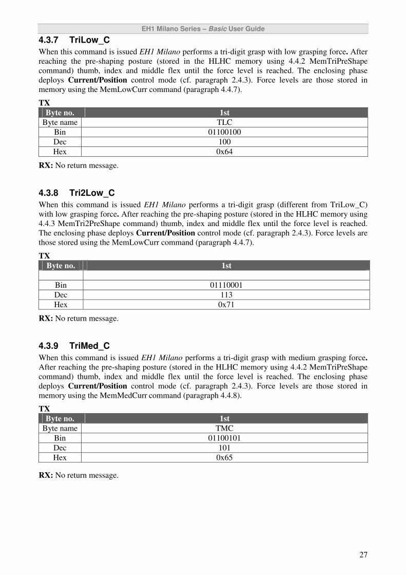
4.3.7 TriLow_C
When this command is issued EH1 Milano performs a tri-digit grasp with low grasping force. After
reaching the pre-shaping posture (stored in the HLHC memory using 4.4.2 MemTriPreShape
command) thumb, index and middle flex until the force level is reached. The enclosing phase
deploys Current/Position control mode (cf. paragraph 2.4.3). Force levels are those stored in
memory using the MemLowCurr command (paragraph 4.4.7).
TX
Byte no. 1st
Byte name TLC
Bin 01100100
Dec 100
Hex 0x64
RX: No return message.
4.3.8 Tri2Low_C
When this command is issued EH1 Milano performs a tri-digit grasp (different from TriLow_C)
with low grasping force. After reaching the pre-shaping posture (stored in the HLHC memory using
4.4.3 MemTri2PreShape command) thumb, index and middle flex until the force level is reached.
The enclosing phase deploys Current/Position control mode (cf. paragraph 2.4.3). Force levels are
those stored using the MemLowCurr command (paragraph 4.4.7).
TX
Byte no. 1st
Byte name T2LC
Bin 01110001
Dec 113
Hex 0x71
RX: No return message.
4.3.9 TriMed_C
When this command is issued EH1 Milano performs a tri-digit grasp with medium grasping force.
After reaching the pre-shaping posture (stored in the HLHC memory using 4.4.2 MemTriPreShape
command) thumb, index and middle flex until the force level is reached. The enclosing phase
deploys Current/Position control mode (cf. paragraph 2.4.3). Force levels are those stored in
memory using the MemMedCurr command (paragraph 4.4.8).
TX
Byte no. 1st
Byte name TMC
Bin 01100101
Dec 101
Hex 0x65
RX: No return message.
EH1 Milano Series – Basic User Guide
28
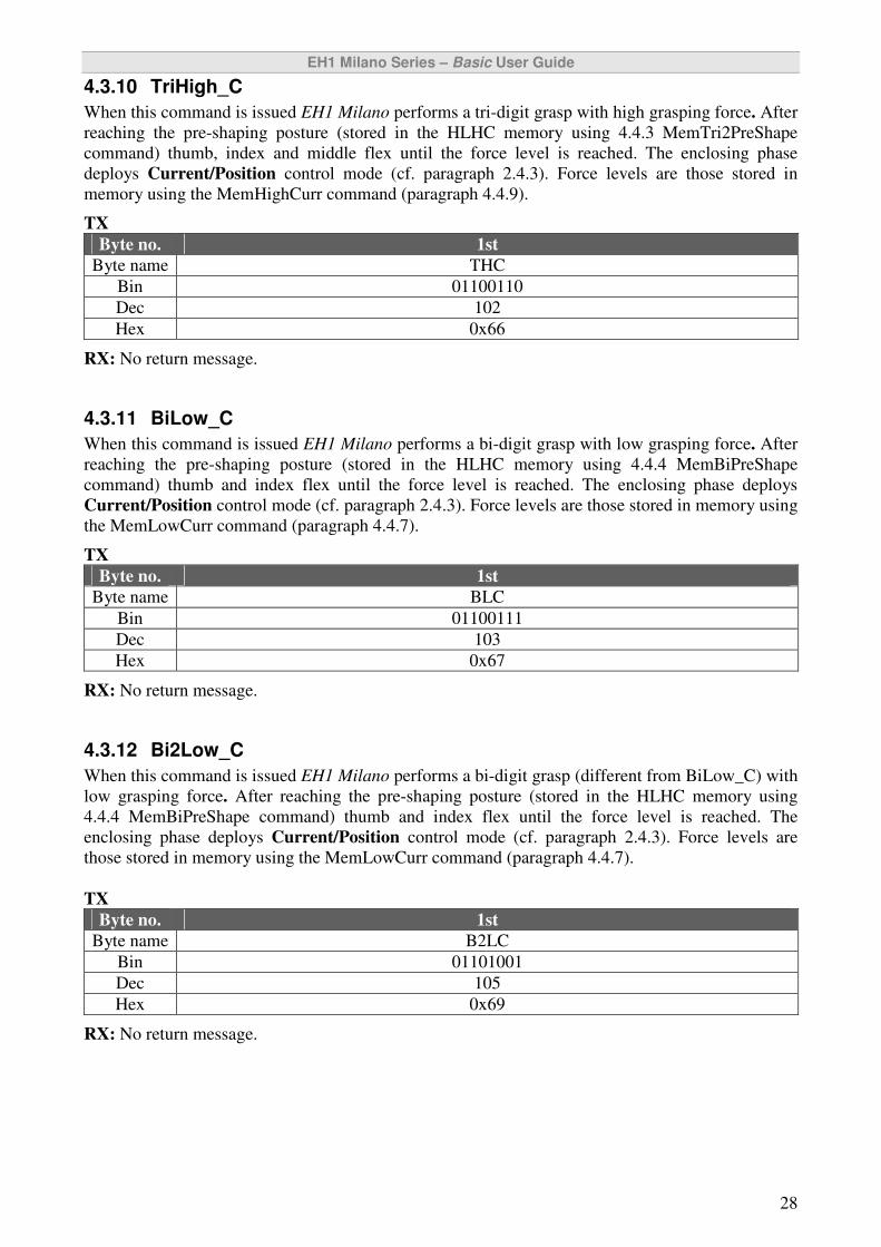
4.3.10 TriHigh_C
When this command is issued EH1 Milano performs a tri-digit grasp with high grasping force. After
reaching the pre-shaping posture (stored in the HLHC memory using 4.4.3 MemTri2PreShape
command) thumb, index and middle flex until the force level is reached. The enclosing phase
deploys Current/Position control mode (cf. paragraph 2.4.3). Force levels are those stored in
memory using the MemHighCurr command (paragraph 4.4.9).
TX
Byte no. 1st
Byte name THC
Bin 01100110
Dec 102
Hex 0x66
RX: No return message.
4.3.11 BiLow_C
When this command is issued EH1 Milano performs a bi-digit grasp with low grasping force. After
reaching the pre-shaping posture (stored in the HLHC memory using 4.4.4 MemBiPreShape
command) thumb and index flex until the force level is reached. The enclosing phase deploys
Current/Position control mode (cf. paragraph 2.4.3). Force levels are those stored in memory using
the MemLowCurr command (paragraph 4.4.7).
TX
Byte no. 1st
Byte name BLC
Bin 01100111
Dec 103
Hex 0x67
RX: No return message.
4.3.12 Bi2Low_C
When this command is issued EH1 Milano performs a bi-digit grasp (different from BiLow_C) with
low grasping force. After reaching the pre-shaping posture (stored in the HLHC memory using
4.4.4 MemBiPreShape command) thumb and index flex until the force level is reached. The
enclosing phase deploys Current/Position control mode (cf. paragraph 2.4.3). Force levels are
those stored in memory using the MemLowCurr command (paragraph 4.4.7).
TX
Byte no. 1st
Byte name B2LC
Bin 01101001
Dec 105
Hex 0x69
RX: No return message.
EH1 Milano Series – Basic User Guide
29
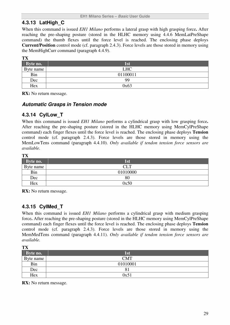
4.3.13 LatHigh_C
When this command is issued EH1 Milano performs a lateral grasp with high grasping force. After
reaching the pre-shaping posture (stored in the HLHC memory using 4.4.6 MemLatPreShape
command) the thumb flexes until the force level is reached. The enclosing phase deploys
Current/Position control mode (cf. paragraph 2.4.3). Force levels are those stored in memory using
the MemHighCurr command (paragraph 4.4.9).
TX
Byte no. 1st
Byte name LHC
Bin 01100011
Dec 99
Hex 0x63
RX: No return message.
Automatic Grasps in Tension mode
4.3.14 CylLow_T
When this command is issued EH1 Milano performs a cylindrical grasp with low grasping force.
After reaching the pre-shaping posture (stored in the HLHC memory using MemCylPreShape
command) each finger flexes until the force level is reached. The enclosing phase deploys Tension
control mode (cf. paragraph 2.4.3). Force levels are those stored in memory using the
MemLowTens command (paragraph 4.4.10). Only available if tendon tension force sensors are
available.
TX
Byte no. 1st
Byte name CLT
Bin 01010000
Dec 80
Hex 0x50
RX: No return message.
4.3.15 CylMed_T
When this command is issued EH1 Milano performs a cylindrical grasp with medium grasping
force. After reaching the pre-shaping posture (stored in the HLHC memory using MemCylPreShape
command) each finger flexes until the force level is reached. The enclosing phase deploys Tension
control mode (cf. paragraph 2.4.3). Force levels are those stored in memory using the
MemMedTens command (paragraph 4.4.11). Only available if tendon tension force sensors are
available.
TX
Byte no. 1st
Byte name CMT
Bin 01010001
Dec 81
Hex 0x51
RX: No return message.
EH1 Milano Series – Basic User Guide
30
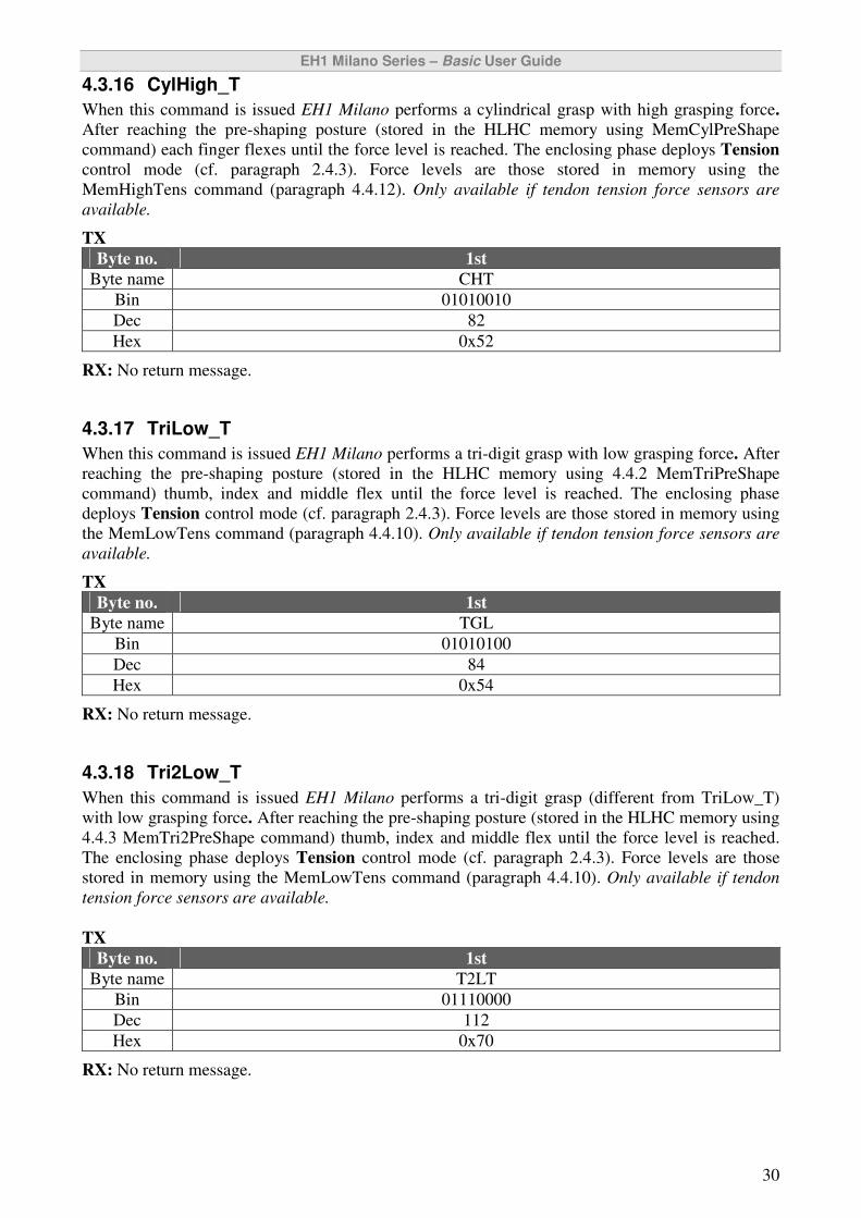
4.3.16 CylHigh_T
When this command is issued EH1 Milano performs a cylindrical grasp with high grasping force.
After reaching the pre-shaping posture (stored in the HLHC memory using MemCylPreShape
command) each finger flexes until the force level is reached. The enclosing phase deploys Tension
control mode (cf. paragraph 2.4.3). Force levels are those stored in memory using the
MemHighTens command (paragraph 4.4.12). Only available if tendon tension force sensors are
available.
TX
Byte no. 1st
Byte name CHT
Bin 01010010
Dec 82
Hex 0x52
RX: No return message.
4.3.17 TriLow_T
When this command is issued EH1 Milano performs a tri-digit grasp with low grasping force. After
reaching the pre-shaping posture (stored in the HLHC memory using 4.4.2 MemTriPreShape
command) thumb, index and middle flex until the force level is reached. The enclosing phase
deploys Tension control mode (cf. paragraph 2.4.3). Force levels are those stored in memory using
the MemLowTens command (paragraph 4.4.10). Only available if tendon tension force sensors are
available.
TX
Byte no. 1st
Byte name TGL
Bin 01010100
Dec 84
Hex 0x54
RX: No return message.
4.3.18 Tri2Low_T
When this command is issued EH1 Milano performs a tri-digit grasp (different from TriLow_T)
with low grasping force. After reaching the pre-shaping posture (stored in the HLHC memory using
4.4.3 MemTri2PreShape command) thumb, index and middle flex until the force level is reached.
The enclosing phase deploys Tension control mode (cf. paragraph 2.4.3). Force levels are those
stored in memory using the MemLowTens command (paragraph 4.4.10). Only available if tendon
tension force sensors are available.
TX
Byte no. 1st
Byte name T2LT
Bin 01110000
Dec 112
Hex 0x70
RX: No return message.
EH1 Milano Series – Basic User Guide
31
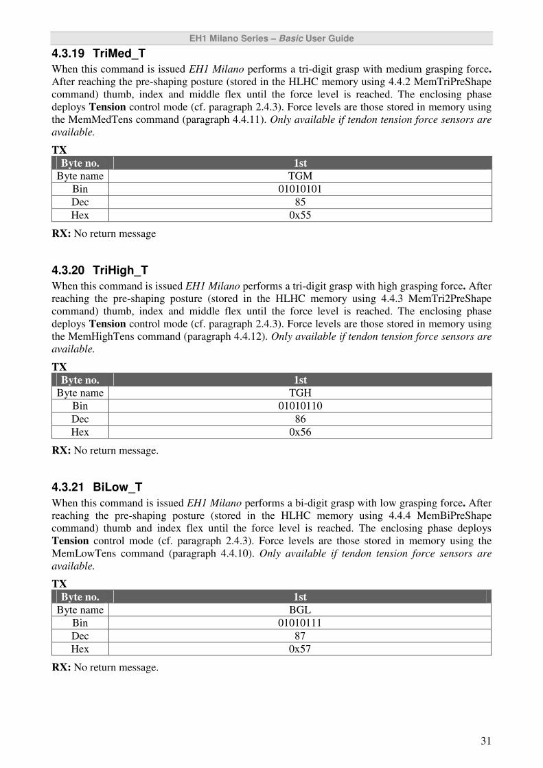
4.3.19 TriMed_T
When this command is issued EH1 Milano performs a tri-digit grasp with medium grasping force.
After reaching the pre-shaping posture (stored in the HLHC memory using 4.4.2 MemTriPreShape
command) thumb, index and middle flex until the force level is reached. The enclosing phase
deploys Tension control mode (cf. paragraph 2.4.3). Force levels are those stored in memory using
the MemMedTens command (paragraph 4.4.11). Only available if tendon tension force sensors are
available.
TX
Byte no. 1st
Byte name TGM
Bin 01010101
Dec 85
Hex 0x55
RX: No return message
4.3.20 TriHigh_T
When this command is issued EH1 Milano performs a tri-digit grasp with high grasping force. After
reaching the pre-shaping posture (stored in the HLHC memory using 4.4.3 MemTri2PreShape
command) thumb, index and middle flex until the force level is reached. The enclosing phase
deploys Tension control mode (cf. paragraph 2.4.3). Force levels are those stored in memory using
the MemHighTens command (paragraph 4.4.12). Only available if tendon tension force sensors are
available.
TX
Byte no. 1st
Byte name TGH
Bin 01010110
Dec 86
Hex 0x56
RX: No return message.
4.3.21 BiLow_T
When this command is issued EH1 Milano performs a bi-digit grasp with low grasping force. After
reaching the pre-shaping posture (stored in the HLHC memory using 4.4.4 MemBiPreShape
command) thumb and index flex until the force level is reached. The enclosing phase deploys
Tension control mode (cf. paragraph 2.4.3). Force levels are those stored in memory using the
MemLowTens command (paragraph 4.4.10). Only available if tendon tension force sensors are
available.
TX
Byte no. 1st
Byte name BGL
Bin 01010111
Dec 87
Hex 0x57
RX: No return message.
EH1 Milano Series – Basic User Guide
32
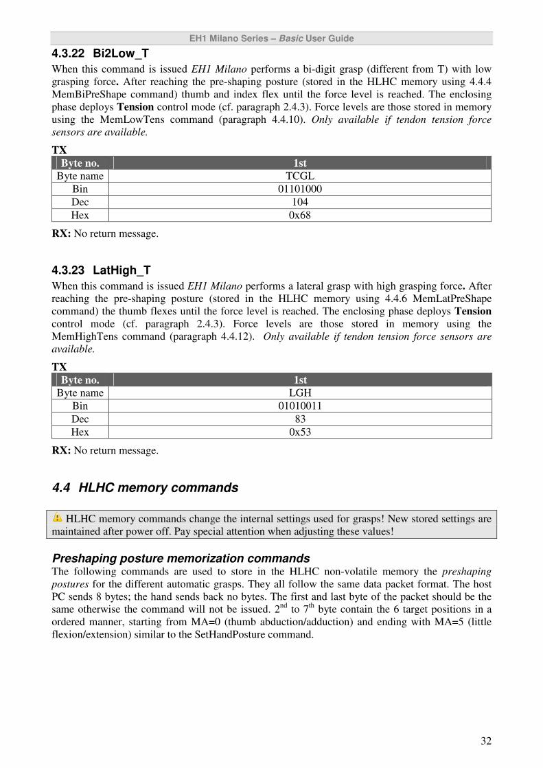
4.3.22 Bi2Low_T
When this command is issued EH1 Milano performs a bi-digit grasp (different from T) with low
grasping force. After reaching the pre-shaping posture (stored in the HLHC memory using 4.4.4
MemBiPreShape command) thumb and index flex until the force level is reached. The enclosing
phase deploys Tension control mode (cf. paragraph 2.4.3). Force levels are those stored in memory
using the MemLowTens command (paragraph 4.4.10). Only available if tendon tension force
sensors are available.
TX
Byte no. 1st
Byte name TCGL
Bin 01101000
Dec 104
Hex 0x68
RX: No return message.
4.3.23 LatHigh_T
When this command is issued EH1 Milano performs a lateral grasp with high grasping force. After
reaching the pre-shaping posture (stored in the HLHC memory using 4.4.6 MemLatPreShape
command) the thumb flexes until the force level is reached. The enclosing phase deploys Tension
control mode (cf. paragraph 2.4.3). Force levels are those stored in memory using the
MemHighTens command (paragraph 4.4.12). Only available if tendon tension force sensors are
available.
TX
Byte no. 1st
Byte name LGH
Bin 01010011
Dec 83
Hex 0x53
RX: No return message.
4.4 HLHC memory commands
HLHC memory commands change the internal settings used for grasps! New stored settings are
maintained after power off. Pay special attention when adjusting these values!
Preshaping posture memorization commands The following commands are used to store in the HLHC non-volatile memory the preshaping
postures for the different automatic grasps. They all follow the same data packet format. The host
PC sends 8 bytes; the hand sends back no bytes. The first and last byte of the packet should be the
same otherwise the command will not be issued. 2nd
to 7th
byte contain the 6 target positions in a
ordered manner, starting from MA=0 (thumb abduction/adduction) and ending with MA=5 (little
flexion/extension) similar to the SetHandPosture command.
EH1 Milano Series – Basic User Guide
33
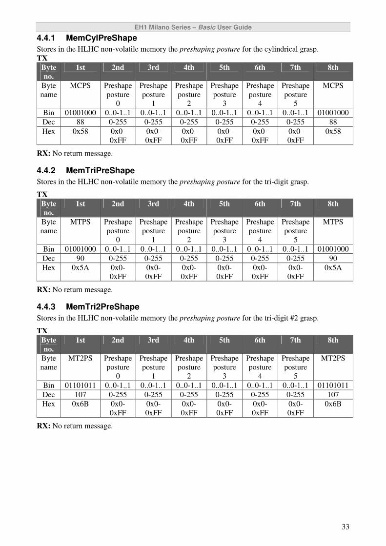
4.4.1 MemCylPreShape
Stores in the HLHC non-volatile memory the preshaping posture for the cylindrical grasp.
TX
Byte
no.
1st 2nd 3rd 4th 5th 6th 7th 8th
Byte
name
MCPS Preshape
posture
0
Preshape
posture
1
Preshape
posture
2
Preshape
posture
3
Preshape
posture
4
Preshape
posture
5
MCPS
Bin 01001000 0..0-1..1 0..0-1..1 0..0-1..1 0..0-1..1 0..0-1..1 0..0-1..1 01001000
Dec 88 0-255 0-255 0-255 0-255 0-255 0-255 88
Hex 0x58 0x0-
0xFF
0x0-
0xFF
0x0-
0xFF
0x0-
0xFF
0x0-
0xFF
0x0-
0xFF
0x58
RX: No return message.
4.4.2 MemTriPreShape
Stores in the HLHC non-volatile memory the preshaping posture for the tri-digit grasp.
TX
Byte
no.
1st 2nd 3rd 4th 5th 6th 7th 8th
Byte
name
MTPS Preshape
posture
0
Preshape
posture
1
Preshape
posture
2
Preshape
posture
3
Preshape
posture
4
Preshape
posture
5
MTPS
Bin 01001000 0..0-1..1 0..0-1..1 0..0-1..1 0..0-1..1 0..0-1..1 0..0-1..1 01001000
Dec 90 0-255 0-255 0-255 0-255 0-255 0-255 90
Hex 0x5A 0x0-
0xFF
0x0-
0xFF
0x0-
0xFF
0x0-
0xFF
0x0-
0xFF
0x0-
0xFF
0x5A
RX: No return message.
4.4.3 MemTri2PreShape
Stores in the HLHC non-volatile memory the preshaping posture for the tri-digit #2 grasp.
TX
Byte
no.
1st 2nd 3rd 4th 5th 6th 7th 8th
Byte
name
MT2PS Preshape
posture
0
Preshape
posture
1
Preshape
posture
2
Preshape
posture
3
Preshape
posture
4
Preshape
posture
5
MT2PS
Bin 01101011 0..0-1..1 0..0-1..1 0..0-1..1 0..0-1..1 0..0-1..1 0..0-1..1 01101011
Dec 107 0-255 0-255 0-255 0-255 0-255 0-255 107
Hex 0x6B 0x0-
0xFF
0x0-
0xFF
0x0-
0xFF
0x0-
0xFF
0x0-
0xFF
0x0-
0xFF
0x6B
RX: No return message.

EH1 Milano Series – Basic User Guide
34
4.4.4 MemBiPreShape
Stores in the HLHC non-volatile memory the preshaping posture for the b-digit grasp.
TX
Byte
no.
1st 2nd 3rd 4th 5th 6th 7th 8th
Byte
name
MBPS Set
Position
0
Set
Position
1
Set
Position
2
Set
Position
3
Set
Position
4
Set
Position
5
MBPS
Bin 01001000 0..0-1..1 0..0-1..1 0..0-1..1 0..0-1..1 0..0-1..1 0..0-1..1 01001000
Dec 91 0-255 0-255 0-255 0-255 0-255 0-255 91
Hex 0x5B 0x0-
0xFF
0x0-
0xFF
0x0-
0xFF
0x0-
0xFF
0x0-
0xFF
0x0-
0xFF
0x5B
RX: No return message.
4.4.5 MemBi2PreShape
Stores in the HLHC non-volatile memory the preshaping posture for the bi-digit #2 grasp.
TX
Byte
no.
1st 2nd 3rd 4th 5th 6th 7th 8th
Byte
name
MB2PS Set
Position
0
Set
Position
1
Set
Position
2
Set
Position
3
Set
Position
4
Set
Position
5
MB2PS
Bin 01101010 0..0-1..1 0..0-1..1 0..0-1..1 0..0-1..1 0..0-1..1 0..0-1..1 01101010
Dec 106 0-255 0-255 0-255 0-255 0-255 0-255 106
Hex 0x6A 0x0-
0xFF
0x0-
0xFF
0x0-
0xFF
0x0-
0xFF
0x0-
0xFF
0x0-
0xFF
0x6A
RX: No return message.
4.4.6 MemLatPreShape
Stores in the HLHC non-volatile memory the preshaping posture for the lateral grasp.
TX
Byte
no.
1st 2nd 3rd 4th 5th 6th 7th 8th
Byte
nam
e
MLPS Set
Position
0
Set
Position
1
Set
Position
2
Set
Position
3
Set
Position
4
Set
Position
5
MLPS
Bin 01001000 0..0-1..1 0..0-1..1 0..0-1..1 0..0-1..1 0..0-1..1 0..0-1..1 01001000
Dec 89 0-255 0-255 0-255 0-255 0-255 0-255 89
Hex 0x59 0x0-
0xFF
0x0-
0xFF
0x0-
0xFF
0x0-
0xFF
0x0-
0xFF
0x0-
0xFF
0x59
RX: No return message.
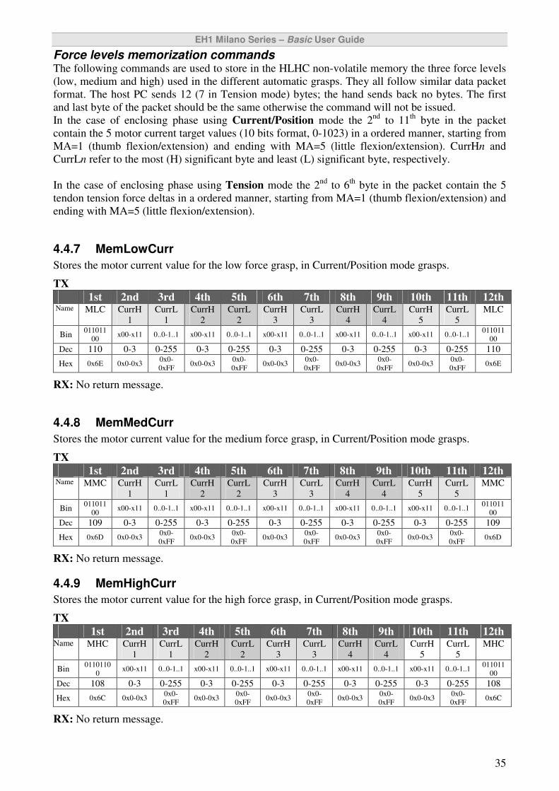
EH1 Milano Series – Basic User Guide
35
Force levels memorization commands The following commands are used to store in the HLHC non-volatile memory the three force levels
(low, medium and high) used in the different automatic grasps. They all follow similar data packet
format. The host PC sends 12 (7 in Tension mode) bytes; the hand sends back no bytes. The first
and last byte of the packet should be the same otherwise the command will not be issued.
In the case of enclosing phase using Current/Position mode the 2nd
to 11th
byte in the packet
contain the 5 motor current target values (10 bits format, 0-1023) in a ordered manner, starting from
MA=1 (thumb flexion/extension) and ending with MA=5 (little flexion/extension). CurrHn and
CurrLn refer to the most (H) significant byte and least (L) significant byte, respectively.
In the case of enclosing phase using Tension mode the 2nd
to 6th
byte in the packet contain the 5
tendon tension force deltas in a ordered manner, starting from MA=1 (thumb flexion/extension) and
ending with MA=5 (little flexion/extension).
4.4.7 MemLowCurr
Stores the motor current value for the low force grasp, in Current/Position mode grasps.
TX
1st 2nd 3rd 4th 5th 6th 7th 8th 9th 10th 11th 12th Name MLC CurrH
1
CurrL
1
CurrH
2
CurrL
2
CurrH
3
CurrL
3
CurrH
4
CurrL
4
CurrH
5
CurrL
5
MLC
Bin 011011
00 x00-x11 0..0-1..1 x00-x11 0..0-1..1 x00-x11 0..0-1..1 x00-x11 0..0-1..1 x00-x11 0..0-1..1
011011
00
Dec 110 0-3 0-255 0-3 0-255 0-3 0-255 0-3 0-255 0-3 0-255 110
Hex 0x6E 0x0-0x3 0x0-
0xFF 0x0-0x3
0x0-
0xFF 0x0-0x3
0x0-
0xFF 0x0-0x3
0x0-
0xFF 0x0-0x3
0x0-
0xFF 0x6E
RX: No return message.
4.4.8 MemMedCurr
Stores the motor current value for the medium force grasp, in Current/Position mode grasps.
TX
1st 2nd 3rd 4th 5th 6th 7th 8th 9th 10th 11th 12th Name MMC CurrH
1
CurrL
1
CurrH
2
CurrL
2
CurrH
3
CurrL
3
CurrH
4
CurrL
4
CurrH
5
CurrL
5
MMC
Bin 011011
00 x00-x11 0..0-1..1 x00-x11 0..0-1..1 x00-x11 0..0-1..1 x00-x11 0..0-1..1 x00-x11 0..0-1..1
011011
00
Dec 109 0-3 0-255 0-3 0-255 0-3 0-255 0-3 0-255 0-3 0-255 109
Hex 0x6D 0x0-0x3 0x0-
0xFF 0x0-0x3
0x0-
0xFF 0x0-0x3
0x0-
0xFF 0x0-0x3
0x0-
0xFF 0x0-0x3
0x0-
0xFF 0x6D
RX: No return message.
4.4.9 MemHighCurr
Stores the motor current value for the high force grasp, in Current/Position mode grasps.
TX
1st 2nd 3rd 4th 5th 6th 7th 8th 9th 10th 11th 12th Name MHC CurrH
1
CurrL
1
CurrH
2
CurrL
2
CurrH
3
CurrL
3
CurrH
4
CurrL
4
CurrH
5
CurrL
5
MHC
Bin 0110110
0 x00-x11 0..0-1..1 x00-x11 0..0-1..1 x00-x11 0..0-1..1 x00-x11 0..0-1..1 x00-x11 0..0-1..1
011011
00
Dec 108 0-3 0-255 0-3 0-255 0-3 0-255 0-3 0-255 0-3 0-255 108
Hex 0x6C 0x0-0x3 0x0-
0xFF 0x0-0x3
0x0-
0xFF 0x0-0x3
0x0-
0xFF 0x0-0x3
0x0-
0xFF 0x0-0x3
0x0-
0xFF 0x6C
RX: No return message.
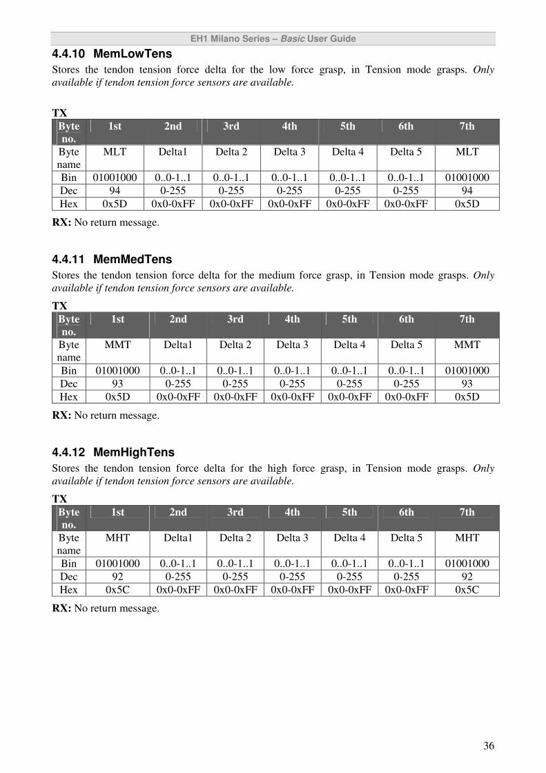
EH1 Milano Series – Basic User Guide
36
4.4.10 MemLowTens
Stores the tendon tension force delta for the low force grasp, in Tension mode grasps. Only
available if tendon tension force sensors are available.
TX
Byte
no.
1st 2nd 3rd 4th 5th 6th 7th
Byte
name
MLT Delta1 Delta 2 Delta 3 Delta 4 Delta 5 MLT
Bin 01001000 0..0-1..1 0..0-1..1 0..0-1..1 0..0-1..1 0..0-1..1 01001000
Dec 94 0-255 0-255 0-255 0-255 0-255 94
Hex 0x5D 0x0-0xFF 0x0-0xFF 0x0-0xFF 0x0-0xFF 0x0-0xFF 0x5D
RX: No return message.
4.4.11 MemMedTens
Stores the tendon tension force delta for the medium force grasp, in Tension mode grasps. Only
available if tendon tension force sensors are available.
TX
Byte
no.
1st 2nd 3rd 4th 5th 6th 7th
Byte
name
MMT Delta1 Delta 2 Delta 3 Delta 4 Delta 5 MMT
Bin 01001000 0..0-1..1 0..0-1..1 0..0-1..1 0..0-1..1 0..0-1..1 01001000
Dec 93 0-255 0-255 0-255 0-255 0-255 93
Hex 0x5D 0x0-0xFF 0x0-0xFF 0x0-0xFF 0x0-0xFF 0x0-0xFF 0x5D
RX: No return message.
4.4.12 MemHighTens
Stores the tendon tension force delta for the high force grasp, in Tension mode grasps. Only
available if tendon tension force sensors are available.
TX
Byte
no.
1st 2nd 3rd 4th 5th 6th 7th
Byte
name
MHT Delta1 Delta 2 Delta 3 Delta 4 Delta 5 MHT
Bin 01001000 0..0-1..1 0..0-1..1 0..0-1..1 0..0-1..1 0..0-1..1 01001000
Dec 92 0-255 0-255 0-255 0-255 0-255 92
Hex 0x5C 0x0-0xFF 0x0-0xFF 0x0-0xFF 0x0-0xFF 0x0-0xFF 0x5C
RX: No return message.

EH1 Milano Series – Basic User Guide
37
5 LLMC commands Each motor (or DoA) is directly actuated and controlled by means of a LLMC that achieves position
control, tendon tension force control7, current (torque) control and monitors motor current
absorption (ensuring a long-life operation of the motor). Each LLMC reads 1 tendon tension force7,
1 motor current, 1 position (encoder) sensor outputs; resolutions are 10, 10 and 17 bits respectively.
The tension sensor is not provided for the thumb abduction/adduction DoF7.
The Low Level Motion Controllers of EH1 Milano, hence the single DoAs, are accessible through
the following set of commands. All these commands follow the same packet format. The packet
size can be four or more bytes long, depending upon the nature of the command being sent to the
hand. Each packet consists of an initial “start of packet” byte, followed by the LLMC Motor
Address byte (to which the command is issued), followed by a “command” specifier byte, followed
by zero or more “command data” bytes, and terminated by the LLMC Motor Address byte. Each
binary packet is at least 4 bytes in length and is formatted as shown below.
7 Tendon tension force sensors are not available on all hands.
95 (0x5F)
MA
Command
Command data
…
Command data
First byte – Start of packet
Second byte - Motor Address
Third byte – Command Value
Command Data Zero or more bytes representing
parameters to the command being
called. See the LLMC command
chart for details.
MA Last byte - Motor Address
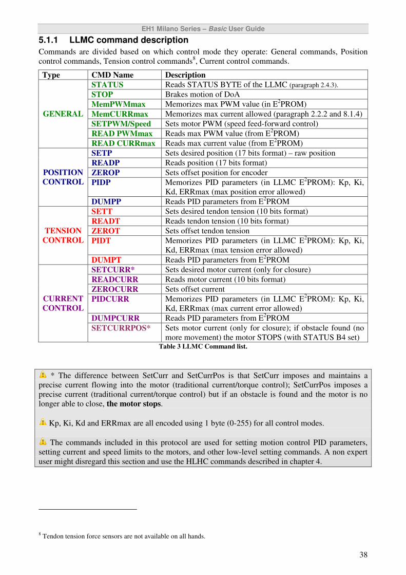
EH1 Milano Series – Basic User Guide
38
5.1.1 LLMC command description
Commands are divided based on which control mode they operate: General commands, Position
control commands, Tension control commands8, Current control commands.
Type CMD Name Description
STATUS Reads STATUS BYTE of the LLMC (paragraph 2.4.3).
STOP Brakes motion of DoA
MemPWMmax Memorizes max PWM value (in E2PROM)
MemCURRmax Memorizes max current allowed (paragraph 2.2.2 and 8.1.4)
SETPWM/Speed Sets motor PWM (speed feed-forward control)
READ PWMmax Reads max PWM value (from E2PROM)
GENERAL
READ CURRmax Reads max current value (from E2PROM)
SETP Sets desired position (17 bits format) – raw position
READP Reads position (17 bits format)
ZEROP Sets offset position for encoder
PIDP Memorizes PID parameters (in LLMC E2PROM): Kp, Ki,
Kd, ERRmax (max position error allowed)
POSITION
CONTROL
DUMPP Reads PID parameters from E2PROM
SETT Sets desired tendon tension (10 bits format)
READT Reads tendon tension (10 bits format)
ZEROT Sets offset tendon tension
PIDT Memorizes PID parameters (in LLMC E2PROM): Kp, Ki,
Kd, ERRmax (max tension error allowed)
TENSION
CONTROL
DUMPT Reads PID parameters from E2PROM
SETCURR* Sets desired motor current (only for closure)
READCURR Reads motor current (10 bits format)
ZEROCURR Sets offset current
PIDCURR Memorizes PID parameters (in LLMC E2PROM): Kp, Ki,
Kd, ERRmax (max current error allowed)
DUMPCURR Reads PID parameters from E2PROM
CURRENT
CONTROL
SETCURRPOS* Sets motor current (only for closure); if obstacle found (no
more movement) the motor STOPS (with STATUS B4 set) Table 3 LLMC Command list.
* The difference between SetCurr and SetCurrPos is that SetCurr imposes and maintains a
precise current flowing into the motor (traditional current/torque control); SetCurrPos imposes a
precise current (traditional current/torque control) but if an obstacle is found and the motor is no
longer able to close, the motor stops.
Kp, Ki, Kd and ERRmax are all encoded using 1 byte (0-255) for all control modes.
The commands included in this protocol are used for setting motion control PID parameters,
setting current and speed limits to the motors, and other low-level setting commands. A non expert
user might disregard this section and use the HLHC commands described in chapter 4.
8 Tendon tension force sensors are not available on all hands.
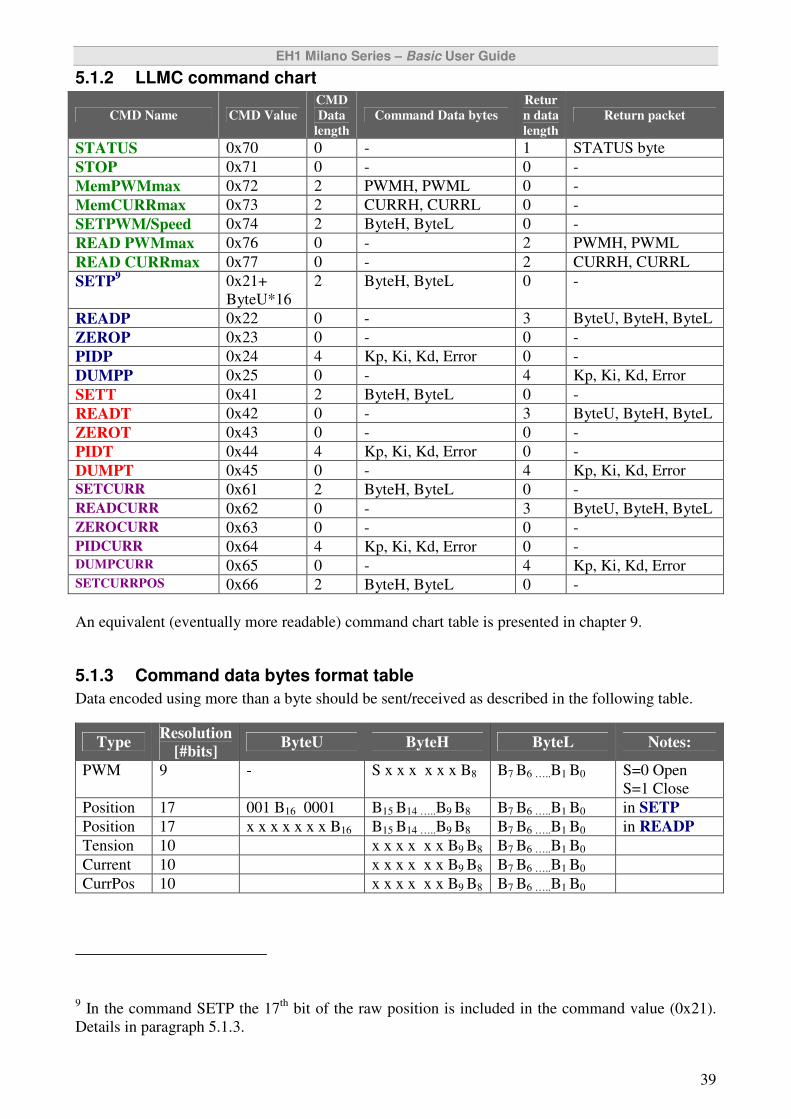
EH1 Milano Series – Basic User Guide
39
5.1.2 LLMC command chart
CMD Name CMD Value
CMD
Data
length
Command Data bytes
Retur
n data
length
Return packet
STATUS 0x70 0 - 1 STATUS byte
STOP 0x71 0 - 0 -
MemPWMmax 0x72 2 PWMH, PWML 0 -
MemCURRmax 0x73 2 CURRH, CURRL 0 -
SETPWM/Speed 0x74 2 ByteH, ByteL 0 -
READ PWMmax 0x76 0 - 2 PWMH, PWML
READ CURRmax 0x77 0 - 2 CURRH, CURRL
SETP9 0x21+
ByteU*16
2 ByteH, ByteL 0 -
READP 0x22 0 - 3 ByteU, ByteH, ByteL
ZEROP 0x23 0 - 0 -
PIDP 0x24 4 Kp, Ki, Kd, Error 0 -
DUMPP 0x25 0 - 4 Kp, Ki, Kd, Error
SETT 0x41 2 ByteH, ByteL 0 -
READT 0x42 0 - 3 ByteU, ByteH, ByteL
ZEROT 0x43 0 - 0 -
PIDT 0x44 4 Kp, Ki, Kd, Error 0 -
DUMPT 0x45 0 - 4 Kp, Ki, Kd, Error
SETCURR 0x61 2 ByteH, ByteL 0 -
READCURR 0x62 0 - 3 ByteU, ByteH, ByteL
ZEROCURR 0x63 0 - 0 -
PIDCURR 0x64 4 Kp, Ki, Kd, Error 0 - DUMPCURR 0x65 0 - 4 Kp, Ki, Kd, Error SETCURRPOS 0x66 2 ByteH, ByteL 0 -
An equivalent (eventually more readable) command chart table is presented in chapter 9.
5.1.3 Command data bytes format table
Data encoded using more than a byte should be sent/received as described in the following table.
Type Resolution
[#bits] ByteU ByteH ByteL Notes:
PWM 9 - S x x x x x x B8 B7 B6 …..B1 B0 S=0 Open
S=1 Close
Position 17 001 B16 0001 B15 B14 …..B9 B8 B7 B6 …..B1 B0 in SETP
Position 17 x x x x x x x B16 B15 B14 …..B9 B8 B7 B6 …..B1 B0 in READP
Tension 10 x x x x x x B9 B8 B7 B6 …..B1 B0
Current 10 x x x x x x B9 B8 B7 B6 …..B1 B0
CurrPos 10 x x x x x x B9 B8 B7 B6 …..B1 B0
9 In the command SETP the 17
th bit of the raw position is included in the command value (0x21).
Details in paragraph 5.1.3.
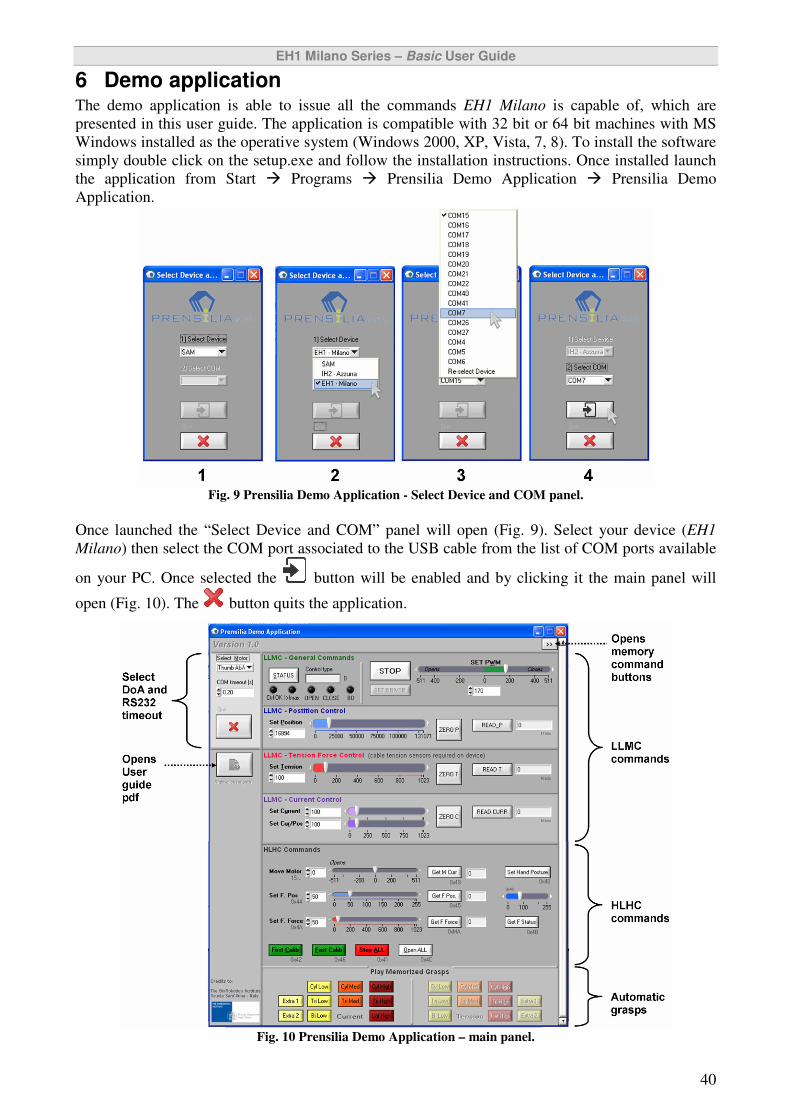
EH1 Milano Series – Basic User Guide
40
6 Demo application The demo application is able to issue all the commands EH1 Milano is capable of, which are
presented in this user guide. The application is compatible with 32 bit or 64 bit machines with MS
Windows installed as the operative system (Windows 2000, XP, Vista, 7, 8). To install the software
simply double click on the setup.exe and follow the installation instructions. Once installed launch
the application from Start � Programs � Prensilia Demo Application � Prensilia Demo
Application.
Fig. 9 Prensilia Demo Application - Select Device and COM panel.
Once launched the “Select Device and COM” panel will open (Fig. 9). Select your device (EH1
Milano) then select the COM port associated to the USB cable from the list of COM ports available
on your PC. Once selected the button will be enabled and by clicking it the main panel will
open (Fig. 10). The button quits the application.
Fig. 10 Prensilia Demo Application – main panel.
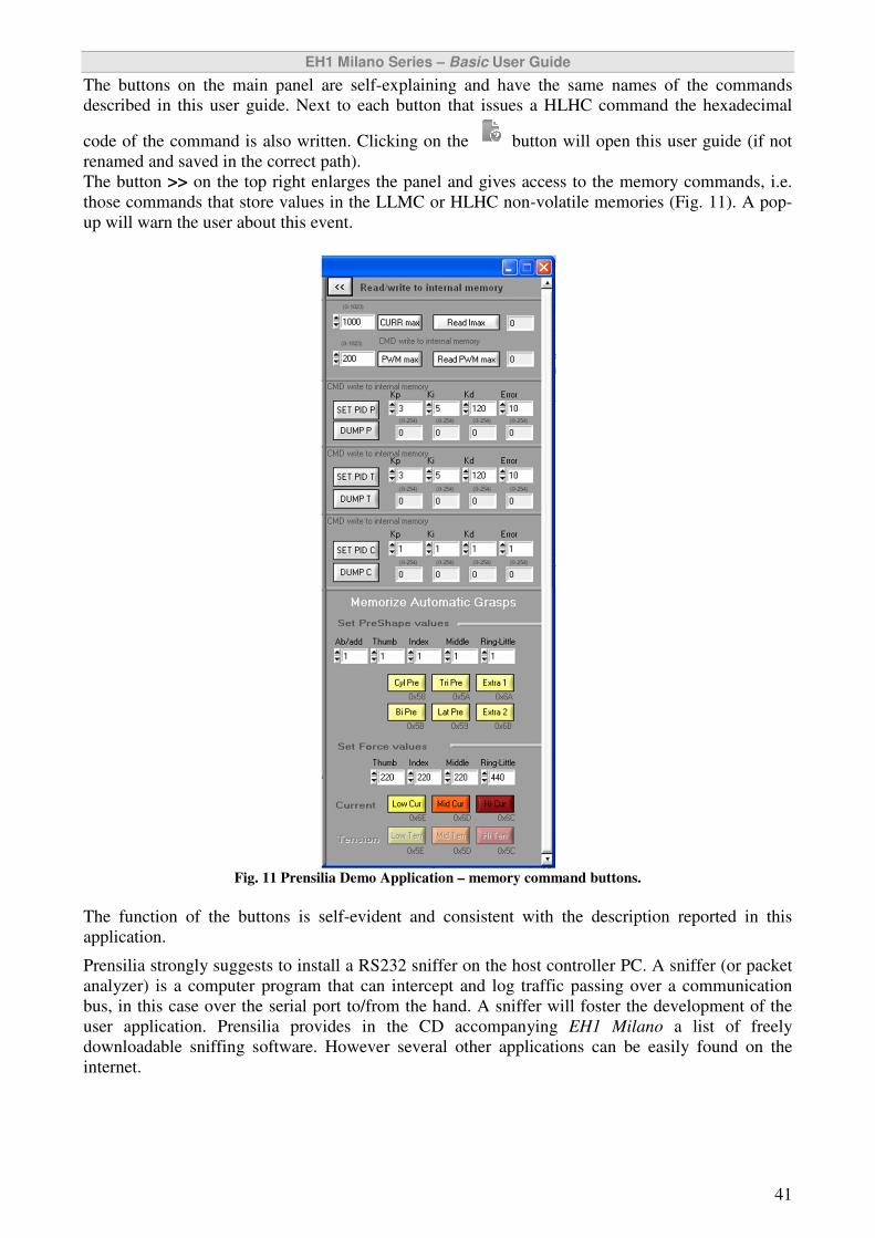
EH1 Milano Series – Basic User Guide
41
The buttons on the main panel are self-explaining and have the same names of the commands
described in this user guide. Next to each button that issues a HLHC command the hexadecimal
code of the command is also written. Clicking on the button will open this user guide (if not
renamed and saved in the correct path).
The button >> on the top right enlarges the panel and gives access to the memory commands, i.e.
those commands that store values in the LLMC or HLHC non-volatile memories (Fig. 11). A pop-
up will warn the user about this event.
Fig. 11 Prensilia Demo Application – memory command buttons.
The function of the buttons is self-evident and consistent with the description reported in this
application.
Prensilia strongly suggests to install a RS232 sniffer on the host controller PC. A sniffer (or packet
analyzer) is a computer program that can intercept and log traffic passing over a communication
bus, in this case over the serial port to/from the hand. A sniffer will foster the development of the
user application. Prensilia provides in the CD accompanying EH1 Milano a list of freely
downloadable sniffing software. However several other applications can be easily found on the
internet.
EH1 Milano Series – Basic User Guide
42
7 Maintenance [Following paragraphs not shown in this version – Available on request]
7.1 Tendon substitution
7.2 Greasing the gears
7.3 Tendon tension force sensor replacement
8 Advanced users
8.1 Control boards architecture
8.1.1 Protecting fuse
8.1.2 Current sensing circuitry – right hand
8.1.3 Current sensing circuitry – left hand
8.1.4 Current sensing limitation
8.2 Embedded motor control algorithms
8.2.1 Position control mode
8.2.2 Current control mode
8.2.3 Current/Position mode
8.3 Programming the HLHC or LLMC firmware
8.4 Thumb abduction/adduction range of movement
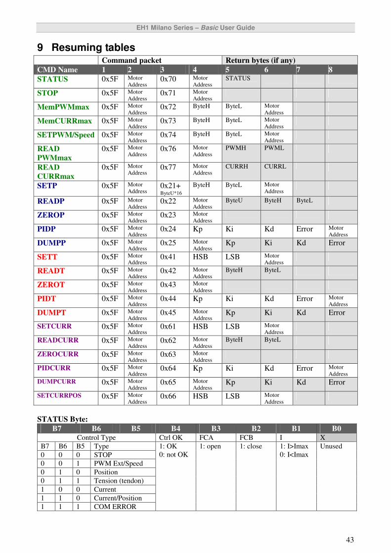
EH1 Milano Series – Basic User Guide
43
9 Resuming tables Command packet Return bytes (if any)
CMD Name 1 2 3 4 5 6 7 8
STATUS 0x5F Motor
Address 0x70 Motor
Address STATUS
STOP 0x5F Motor
Address 0x71 Motor
Address
MemPWMmax 0x5F Motor
Address 0x72 ByteH
ByteL Motor
Address
MemCURRmax 0x5F Motor
Address 0x73 ByteH ByteL Motor
Address
SETPWM/Speed 0x5F Motor
Address 0x74 ByteH ByteL Motor
Address
READ
PWMmax
0x5F Motor
Address 0x76 Motor
Address PWMH PWML
READ
CURRmax
0x5F Motor
Address 0x77 Motor
Address CURRH CURRL
SETP 0x5F Motor
Address 0x21+ ByteU*16
ByteH
ByteL Motor
Address
READP 0x5F Motor
Address 0x22 Motor
Address ByteU ByteH ByteL
ZEROP 0x5F Motor
Address 0x23 Motor
Address
PIDP 0x5F Motor
Address 0x24 Kp Ki Kd Error Motor
Address
DUMPP 0x5F Motor
Address 0x25 Motor
Address Kp Ki Kd Error
SETT 0x5F Motor
Address 0x41 HSB LSB Motor
Address
READT 0x5F Motor
Address 0x42 Motor
Address ByteH ByteL
ZEROT 0x5F Motor
Address 0x43 Motor
Address
PIDT 0x5F Motor
Address 0x44 Kp Ki Kd Error Motor
Address
DUMPT 0x5F Motor
Address 0x45 Motor
Address Kp Ki Kd Error
SETCURR 0x5F Motor
Address 0x61 HSB LSB Motor
Address
READCURR 0x5F Motor
Address 0x62 Motor
Address ByteH ByteL
ZEROCURR 0x5F Motor
Address 0x63 Motor
Address
PIDCURR 0x5F Motor
Address 0x64 Kp Ki Kd Error Motor
Address
DUMPCURR 0x5F Motor
Address 0x65 Motor
Address Kp Ki Kd Error
SETCURRPOS 0x5F Motor
Address 0x66 HSB LSB Motor
Address
STATUS Byte:
B7 B6 B5 B4 B3 B2 B1 B0 Control Type Ctrl OK FCA FCB I X
B7 B6 B5 Type
0 0 0 STOP
0 0 1 PWM Ext/Speed
0 1 0 Position
0 1 1 Tension (tendon)
1 0 0 Current
1 1 0 Current/Position
1 1 1 COM ERROR
1: OK
0: not OK
1: open 1: close 1: I>Imax
0: I<Imax
Unused

EH1 Milano Series – Basic User Guide
44
MoveMotor 1 S MA3..MA0 X D8 D7..D0 S=1 closes, S=0 opens SetFingerPosition 0x44 Motor no. Molt
SetFingerForce 0x4A T9 T8 x x MA3..MA0 T7..T0
GetFingerPosition 0x45 Motor no. Returns actual position
GetFingerForce 0 0 xx MA3..MA0 Rx 10 bit force xxxxxx T9 T8 T7..T0
GetMotorCurrent 0x49 Motor no. Rx 10 bit current xxxxxx C9 C8 C7..C0
GetFingerStatus 0x4B Motor no. Rx: status byte
OpenALL 0x4C
FirstCalibration 0x42
FastCalibration 0x46
StopALL 0x41
SetHandPosture 0x48 Molt0 Molt1 Molt2 Molt3 Molt4 0x48
CylLow_T � 0x50 CylMed_T � 0x51 CylHigh_T � 0x52
LatHigh_T � 0x53 TriLow_T � 0x54 TriMed_T � 0x55
TriHigh_T � 0x56 BiLow_T � 0x57
CylLow_C 0x60
CylMed_C 0x61
CylHigh_C 0x62
LatHigh_C 0x63
TriLow_C 0x64
TriMed_C 0x65
TriHigh_C 0x66
BiLow_C 0x67
MemCylPreShape 0x58 Molt0 Molt1 Molt2 Molt3 Molt4 0x58
MemLatPreShape 0x59 Molt0 Molt1 Molt2 Molt3 Molt4 0x59
MemTriPreShape 0x5A Molt0 Molt1 Molt2 Molt3 Molt4 0x5A
MemBiPreShape 0x5B Molt0 Molt1 Molt2 Molt3 Molt4 0x5B
MemHighTens 0x5C Delta1 Delta2 Delt3 Delt4 0x5C
MemMedTens 0x5D Delta1 Delta2 Delt3 Delt4 0x5D
MemLowTens 0x5E Delta1 Delta2 Delt3 Delt4 0x5E
MemHighCurr 0x6C CurrH1 CurrL1 CurrH2 CurrL2 CurrH3 CurrL3 CurrH4 CurrL4 CurrH5 CurrL5 0x6C
MemMedCurr 0x6D CurrH1 CurrL1 CurrH2 CurrL2 CurrH3 CurrL3 CurrH4 CurrL4 CurrH5 CurrL5 0x6D
MemLowCurr 0x6E CurrH1 CurrL1 CurrH2 CurrL2 CurrH3 CurrL3 CurrH4 CurrL4 CurrH5 CurrL5 0x6E
MemBi2PreShape 0x6A Molt0 Molt1 Molt2 Molt3 Molt4 Molt5 0x6A
MemTri2PreShape 0x6B Molt0 Molt1 Molt2 Molt3 Molt4 Molt5 0x6B
Bi2Low_T 0x68
Bi2Low_C 0x69
Tri2Low_T 0x70
Tri2Low_C 0x71 IH2 Firmware Version: HLHC (hlhcx6_14012013.c), LLMC (llmc_05012013), SAM (SAMXEH_14012013.c)

EH1 Milano Series – Basic User Guide
45
Via Boccioni, 2
56037 Peccioli (PI), Italy
www.prensilia.com
© 2009-2013 Prensilia S.r.l.
EH1 – Extrinsic Robotic Hand User Guide - Version 1.0
January 2013
Printed in Italy
All other trademarks mentioned in the text are the property of their respective owners.