eftigmeeriftic - pearl-hifi.com · guaranteed splice -free ... on request at the same price. trade...
TRANSCRIPT


NEW 7" REELS OF
audiotap: give you EXTRA VALUE at no extra cost
GUARANTEED SPLICE -FREE
SPLIT -SECOND TIMING with New 23/" Hub
Improved reel design reduces timing errors by decreasing tension and speed changes throughout the winding cycle. Ratio of OD to hub diameter is the same as on the standard NAB 2500 -ft. reel. .4r
PERFECTED ANTI- FRICTION PROCESS. Reduces head wear -eliminates annoying tape "squeal" - prevents "tackiness" even under extreme temperature and humidity conditions.
MAXIMUM UNIFORMITY OF OUTPUT. All 7" and 10" reels of plastic - base Audiotape are guaranteed to have an out- put uniformity within ± ' /4db - and reel -to- reel- variation of less than ± ' /2db. What's more, there's an actual output curve in every 5 -reel package to prove it.
With Audiotape, all of these extra -value features are standard. There's no extra cost - no problem of separate inventories or variations in tape quality.
For there's only one Audiotape - the finest obtainable anywhere. Test it - compare it - let Audiotape speak for itself.
The new 7 -inch plastic reel with large diameter hub for greater timing accuracy is now being supplied on all orders unless other- wise specified. Because of increased hub diameter. maximum reel capacity is slightly over 1200 feet. Older style Audiotape reels with 13/4" hub and 1250 feet of tape will continue to be furnished on request at the same price. Trade Mark
AUDIO DEVICES, Inc. 444 Madison Ave., New York 22, N.Y.
Export Department, 13 East 40th St., New York 16, N. Y., Cables "ARIAS"
www.americanradiohistory.com

t
t
Successor to 1173:4c.7 -Established 1917
ElIWGINEERIirG
INCLUDING
C. G. McProud, Editor and Publisher Harrie K. Richardson, Associate Editor Eve Drolet, Production Manager Elizabeth Beebee, Circulation Manager Edgar E Newman, Circulation Promotion
Edgar M. Villchur, Contributing Editor Henry A. Schober, Business Manager S. L. Cahn, Advertising Director H. N. Reizes, Advertising Manager
Editorial Advisory Board
Howard A. Chinn
John D. Calvin
C. J. LeBel
J. P. Maxfield
George M. Nixon
Representatives
H. Thorpe Covington, Special Representative 677 N. Michigan Ave., Chicago 11, Ill.
Sanford R. Cowan, Mid -West Representative 67 W. 44th St., New York 18, N. Y. James C. Galloway, Pacific Coast Sales 816 W. 5th St., Los Angeles 17, Calif.
Technical Book G Magazine Co. 297 Swanston St., Melbourne, C. I.
Victoria, Australia
CONTENTS DECEMBER, 1952 Vol. 36, No. 12
Audio Patents - Richard H. Dorf 2
Letters 4
New Literature 9
Editor's Report 10
Audio Engineering Society News 12
Connsonata Organ Installation for the 1952 Presidential Nominating Con- vention -Serge L. Krauss and Karl Kramer 15
A Discussion of Dividing Networks -J. P. Wentworth 17
Simplified Equalizer Design- George A. Douglas 18
Handbook of Sound Reproduction -Chapter 7-E. M. Villchur 20
Speaker Treatment for Improved Bass -R. Cameron Barritt 23
AUDIO engineering society SECTION
Wide-Angle Dispersion of H.F. Sound -Abraham B. Cohen 24
Audio Fair Review -Harrie K. Richardson 26 Record Revue - Edward Tatnall Canby 34 New Products 46 Errata 56
Book Reviews 59
Industry Notes 61
Annual Index 62
COVER
View of the interior of the Chicago Amphitheatre showing the mounting of the loudspeaker gondola used with the Connsonata organ installation for the two presidential nominating conventions held there last July. Consisting of three
separate channels fed by a multiamplifier system, this type of installation - described by Serge L. Krauss and Karl Kramer beginning on page 15- eliminated the need for an expensive and almost impossible pipe organ installation to provide this traditional type of music. The organist shown in the insert is William McMains who, with Harold M.
Anderson, furnished the music throughout the two hectic weeks.
RADIO MAGAZINES, INC., P. 0. BOX 629, MINEOLA, N. Y. ÁLD10 ENGINEERING (title registered U. S. Pat. OR. ) Is published monthly at 10 McGovern Avenue. Lancaster, Pa. , by Radie Mapaine. Inc., Henry A. Schober, President; C. G. McProud, Secretary. Executive and Editorial (Maces; 294 Front RI, Mineola, N. T. Subscription rates -United Stated, U. S. Poweeslons and Canada, 43.00 for 1 year. 45.00 for 2 years; elsewhere 44.00 per year. Single copies 35c. Printed to U. S. A. All rights reserved. Entire contents eeeyrltht 1952 by Radio 5fagazlnes, The. Entered as Second Claw Matter Febnmry 9, 1950, at the Post Office, Lan-
caster, Pa. under the Art of starch 3. 1879.
AUDIO ENGINEERING DECEMBER, 1952
GOOD NEWS!
the
REK -O -KUT TURNTABLE with the
HYSTERESIS MOTOR
is AGAIN AVAILABLE!
Nothing Else
Can J:',ompare!
REK -O -KUT Motels T -12H and T -43H
E]LIPPED WIT-I THE
Hyste-esis Synchronous Motor
... lie only dual speed, 12" turntabl?s that meet the standards for speed regulation and wow content specified by the National Associcion of Broadcasters ... and recommended by every leading Sound Authority for use with ULTRA -UGH FIDELITY Amplifiers and Speaker Systems. T -12H 78 cnd 33t/3 RPM $119.95 T -43H 33V, and 4.5 RPM $119.95
T-10
T-104is
ACCESSORIES: e5 RPM idler. with record cda'tor, interchangeable .
3t/' RPM. 8 RP
with 4
38 -01 Queens Blvd.,
uMR- ly,so %. afe eroe CANADA Alla -. lati) Clip.. ile. 5
www.americanradiohistory.com

New Portable Battery -Operated
Spring -Motor Tape Recorder
For all field recording without AC power! Smaller and lighter than a portable type- writer, the Magnemite° actually makes field recordings that can be played on any studio console equipment. Completely self -powered, the Magnemite* does away with bulky and cumbersome generators, storage batteries and rechargers.
Just check these unusual features:
Noiseless and vibrationless governor - controlled spring -motor assures constant tape speed.
100 operating hours per set of inexpensive flashlight -type dry cell batteries.
Earphone monitoring while recording, and earphone playback for immediate quality chec c.
Operates in any position, and is unaffected by movement or vibration during operation.
Warning indicator tells when to rewind, and shows when amplifier is on.
Broadcast models weigh 15 pounds. Slow - speed models weigh only 10 pounds.
Requires no more desk space than a letter- head, measuring only Ilea x5 V2 inches.
There's a choice of 5 different models for any recording need. High fidelity units, meeting primary and secondary NARTB standards, which record and play back frequencies up to 15,000 cycles, are avail- able for broadcast stations, critical music lovers, and scientific research. For investi- gation, missionaries, reporters, and general dictation while traveling, there are units which play up to 2 hours per reel of tape.
Write today jot complete descriptive literature and direct factory prices.
CAMPLIFIER CORP.
of AMERICA 398 Broadway, N. Y. 13, N. Y.
VOLUME compressors are not usually used in high -quality home reproduc- ing equipment but they are very
definitely needed in other systems, such as broadcasting and recording, where the normal dynamic range of program material must be compressed to fit the capabilities of the recording or transmission medium. Theoretically, the ideal compressor varies its gain instantly in exact accordance with signal level, with only sufficient delay to integrate at the lowest audio frequencies to prevent the action from following the con- tours of individual audio cycles.
Unfortunately most compressor designs do not allow that because a sudden change in level, such as would occur with the ideal compressor. produces a steep -wavefront transient resulting in a momentary cutoff of signal. The sound is quite objectionable, and most designs compromise by providing a longer delay, so that the changes in gain are comparatively slow. That delay, how- ever, defeats in part the purpose of the compressor. A sudden signal peak can easily go through the system at full amplitude, with compression beginning after the dam- age has been done.
Another fault with most designs results from the use of a variable -mu pentode as the control tube, with controlling bias de- rived from rectified and filtered signal taken from later stages. As the controlling bias varies, so does the control -tube screen volt- age, often taking it out of the region of maximum curvature of the tube character- istic and reducing the control action.
* 255 W. 84th St., New York 24, N. Y.
LW
tIVLWg120 RICHARD H. DORF'
Both these major difficulties seem to have been solved by David E. Roberts of Chi- cago, Ill., in his patent No. 2,596,510, as- signed to Motorola. The patent describes the compressor shown in the diagram, which is said to allow very fast action without clicks or thumps and has a stabilized screen circuit. The principle allowing the fast action is the clipper tube V,. The undesir- able transient has a level many times greater than that of the signal. V. clips the transient and removes the thump without disturbing the desired signal. It also stabi- lizes the control -tube screen.
Input signal goes to the grid of V, (which is a variable -mu pentode) through conven- tional blocking capacitor C. R, is the grid leak, bypassed to ground by C. Signal from a later stage of the amplifier is fed through C, to a fairly conventional rectifier and filter circuit which includes R. and R, as well as C, and C,. This serves to produce d.c. and to reduce the ripple to a frequency below the audio band. Thus, while the d.c. will rise and fall with over -all signal level, it cannot rise and fall with individual audio cycles. The d.c. output of the rectifier -filter is applied to the grid of V. through R, and controls the tube's gain. So far the idea follows standard compressor practice, ex- cept that the time constant of the d.c. filter is as short as possible to allow fast compres- sion.
R, is the V, plate load resistor and R.-C, is a power -supply decoupling network of the usual kind. The output signal of V, is fed through C, to the following amplifier.
[Continued on page 451
AUDIO ENGINEERING DECEMBER, 1952
www.americanradiohistory.com

SILFCTROC-CORES... BI G or LITTLE ...any quantity and any size
wo-totd
,PA - ns.coit-
7-eá 25
For users operating on government schedules, Arnold is now produc- ing C -Cores wound from 1/4, 1 /2, 1, 2, 4 and 12 -mil Silectron strip. The ultra -thin oriented silicon steel strip is rolled to exacting toler- ances in our own plant on precision cold -reducing equipment of the most modern type. Winding of cores, processing of butt joints, etc. are carefully controlled, assuring the lowest possible core losses, and freedom from short- circuiting of the laminations.
We can offer prompt delivery in production quantities -and size is no object, from a fraction of an ounce to C -Cores of 200 pounds or more. Rigid standard tests -and special electrical tests where required -give ycu assurance of the highest quality in all gauges. Your inquiries are invited.
PIE ARNOLD ENGINEERING
AUDIO ENGINEERING DECEMBER. 1952
SUBSIDIARY OF ALLEGHENY LUDLUM S-EEL
General Office & Plant: Marengc .i-
www.americanradiohistory.com

here's
absolute reliability
for heavy duty
audio
amplification
i
If you've been looking for an audio output tube that's stable under the most severe conditions- completely dependable - then this is it! The Tung -Sol 5881 is rugged both mechanically and electrically -and directly interchangeable with the 6L6.
In creating the 5881, Tung -Sol engineers have made lavish use
of the design and production techniques which have proved them- selves over the past fifteen years -zirconium coating over the
carbonized metal plate and pure barium getter to effectively absorb gas for the life of the tube -gold plated wire to minimize grid emission. These are but a few of the major design improve-
ments in the 5881.
Tung -Sol produces the 5881 under laboratory conditions, to assure peak efficiency and maximum uniformity. You'll find this
tube has the stuff to take the whole range of audio service require- ments from protracted standby periods to repeated heavy over- loads. So, if absolute reliability is essential in your audio circuits,
the Tung -Sol 5881 is a "must." Order it from your regular supplier.
Write for characteristics and performance dato
TUNG -SOL ELECTRIC INC., NEWARK 4, N. J.
Sales Offices: Atlanta Chicago Culver City (Calif.) Dallas Denver Detroit Newark
T enpSol makes All .Glass Sealed Beam Lamps, II Inlatere Lamps, Signal Flashers, Plaken Tabes. 'ladle, TV and
Special Purpose Eleetron Tubes.
LETTERS The Ravanastron
SIR :
Wishing to contribute kith additional enlightenments concern- ing the Ravanastron -the forerunner of the violin -mentioned in the article by Mr. Albert Preisman in your September issue, we ask permission to quote the well known work of Albert Lavigne' "La Musique et les Musiciens," 1919 edition, in which the author states:
"I have had the occasion of hearing the Marquis of Tseng, then ambassador from China in Paris, playing a Ravanastron, or Chinese violin, of my property. The instrument is peculiar in the fact that the bow remains constantly tied to, i.e., inter- laced between the two strings, which are tuned in fifths. To play the Ravanastron one has to move the bow backwards or forward, rubbing it against either string. "Saint -Saëns heard the Ravanastron at will in China, even trying to play it, but without success. He finds a charm in this primitive instrument, 'essentially Chinese,' to \which the listeners quickly adjust themselves. Saint -Saëns wrOte to me: 'It is often barbaric but not discordant.' " We wish to add that the drawing which illustrates Mr. Preis -
man's article, besides showing the bow detached from the instru- ment, fails to include the bridge upon which the strings rest and which transmits their vibrations to the membrane of the sound box. The Ravanastron has all the essential elements of the violin, namely : strings made of gazelle guts, bridge, sound box, finger board, pegs, and bow.
PERM DE CAMPOS FRANCISCO M. D. LEAD Sao Paulo, Brazil
I Albert Lavignac, professor of Harmony at the Paris Con- servatory. See Grove's Dictionary of Music and Musicians.
Stylus Force or Stylus Pressure?
SIR: It seems to me that writers who discuss stylus and record
wear confuse the terms "force" and "pressure." The force of friction which may dislodge particles from either the stylus or the record is that portion of the weight of the pickup arm that is supported by the stylus, multiplied by the coefficient of friction. This coefficient is determined by the nature of the record sur- face and the speed of the turntable. Obviously the only numeri- cal values we know are the turntable speed and the weight of the arm assembly. That it is absurd to assign a value to the pressure can be shown by the following consideration:
Assume a perfect record and a perfect stylus. Then the stylus rests in the groove along a line normal to the groove, the area of which approaches zero as a limit. Since the pressure is equal to force divided by area, the pressure approaches infinity as long as the arm assembly weighs anything at all. Assume a little wear and the pressure is anything between zero and infinity.
ERVIN J. LAGER 221 South Tenth East, Salt Lake City, Utah.
These Complex Fruddians SIR:
I do not know whether you value readers' opinions (definitely. ED.) or even have the time to read them. However, I will state that I frankly can do without such articles as "The Frudd Audio System." It doesn't strike me as even humorous and the rest of your material is so very good. Even the ads are informative.
THOMAS W. CRANE, 31 Haven Road. South Portland, Me.
SIR: After reading the item about the Frudd Audio system, I must
protest. This type of humor is too close to a very considerable percentage of your more serious efforts. Consider the following examples
Your November cover is a classic. The equipment would un- doubtedly have even higher fidelity if the tuning knobs were located on the bottom of the box.
Recently you have published a humorously -large number of articles on the Williamson amplifier. The one by Kiebert in the August issue is an outstanding example. After bringing this amplifier up to date, Kiebert gets 7.23 watts output at 1 per cent distortion without feedback and 8.8 watts with feedback. Wil- liamson (Wireless World, May 1947) got 16 watts output at 1
per cent distortion without feedback and at 0.15 per cent distor-
AUDIO ENGINEERING DECEMBER, 1952
www.americanradiohistory.com

IIIIF'141011P+/r 1
SOUN D CRAFT RMCORDING TAPE
SDUNDCRAFT Merry snUNDC Christmas ._o.... K...,...
recording III wh the, Reeves a
SOUNDCRAFT -- -» r TAPE-CHEST
n the P 5 Reels of Soundcraft Recording Tape
In a Permanent, Handsome Caoinet
Recording tape enthusiasts would be happy to get Soundcraft high fidelity Tape for Christmas. But imagine their joy, their delight, when they receive 5 reels of Soundcraft tape - neatly stored and attractively pack- aged in the Soundcraft Tape- Ci-estl
The Tape -Chest is the ideal way to file and
0yYalr6+°' .
AUDIO ENGINEERING DECEMBER, 1952
5 protect recording reels. It's sturdily con- structed, for long- lasting durability. It stores either 5" or 7" reels, each in a separate drawer. And it's yours for the giving at no extra cost, with the purchase of 5 reels of high -fidelity Soundcraft Tape.
So make this a very Merry Christmas for the tape fans on your gift list. Visit your nearest dealer, and ask for Soundcraft Tape in the convenient Tape -Chestl
Write for complete information to;
REEVES
f! _ CORP. 0 East 52nd Street, N. Y. 22, N. Y.
THE ONLY RECORDING MATERIALS PERFECTED
AND MANUFACTURED BY RECORDING SPECIALISTS
www.americanradiohistory.com

Coming Up- Perfect
Precision Prints
"SELECTIVE PRINTING FOR EVERY SCENE"
This is one of the essential depart- ments at Precision which doesn't depend on automatic machinery. Only intelligence and skill can be depended on to select a timing value for the correct printing of essential elements. That's what you get in a Precision timed print -a selective printing exposure for every scene.
YOUR ASSURANCE OF BETTER 16mm PRINTS
15 Years Research and Spe- cialization in every phase of 16mm processing, visual and aural. So organized and equip- ped that all Precision jobs are of the highest quality.
Individual Attention is given each film, each reel, each scene, each frame - through every phase of the complex business of processing - assuring you of the very best results.
Our Advanced Methods and our constant checking and adop- tion of up- to- the -minute tech- niques, plus new engineering principles and special machinery
Precision Film Laboratories -a di- vision of J. A. Maurer, Inc., has 14 years of specialization in the 16mm field, consistently meets the latest de- mands for higher quality and speed.
enable us to offer service un- equalled anywhere!
Newest Facilities in the 16mm field are available to customers of Precision, including the most modern applications of elec- tronics, chemistry, physics, optics, sensitometry and densitometry- including exclusive Maurer - designed equipment -your guar- antee that only the best is yours at Precision!
PR CJSÏON FILM LABORATORIES, INC.
21 West 46th St.,
New York 19, N.Y. JU 2 -3970
1
tion with feedback. Kiebert daims to have improved the noise level of the amplifier by 12 db by using a wire -wound resistor in the plate circuit of the first stage, but that no significant change resulted from the same procedures in the following phase -splitter stage. This is funny, because the audio levels are about the same in both stages. In any case, he must be talking about noise levels which are humorously below the point of significance.
In conclusion, let me say that I find every issue of your magazine interesting and entertaining much more so than that other well known New York humor magazine alled "
HARVEY KEES, 3312 Lake Drive, Evansville Indiana
SIR:
This letter is being written to compliment Mr. D. B. Frudd on his article in the November issue of 2E.
We are enclosing our latest bulletin on the Tri- Stable Two -Stage Caloriferer with Biased Viewpoint Adjustment which might prove of interest to you.
R. T. FISHER, Pres., Sigma Instruments, Inc., 70 Pearl St., So. Braintree, Boston 85, Mass.
SIR :
I noted the little item on the Frudd Sys- tem with a big grin on my face. It created quite a bit of comment here among the wheels at Hazeltine. We thought it was pretty good. Shades of the Flewelling Sys- tern-may both he and his system rest in peace. . . .
TED POWELL, 42 Nassau Road, Great Neck, N. Y.
SIR:
After reading with interest Dr. D. B. Frudd's article on the epitome of audio sys- tems, I proceeded with the construction of an amplifier to his specifications. Having just completed and tested this instrument, I wish to offer a few comments thereon....
Regarding the construction itself, I felt that merely a solid aluminum chassis would not provide the ultimate stability for which all audio enthusiasts thirst. Therefore, I tried a large steel block mounted upon concrete piles, with gratifying results. To those readers who do not wish to smelt steel to order for the amplifier, I suggest the use of the motor block from an old automobile engine
Bernard A. Engholm, Oak Ridge National Laboratory, P. O. Box P., Oak Ridge, Tenn.
(One stage in each cylinder? Good shield- ing, that, En.)
SIR :
... Aluminum was unavailable and I happened to use stainless steel, which I do not recommend as it is hard to work with the small hand tools, consisting of nail file and letter- opener, which were at my dis- posal. Actually I was so fatigued by this operation that when I found I had omitted cavities for the seventeen internal and three external loops I decided to simply wrap them about the chassis. This is not a neat job, but it serves very well, and is
[Continued on page 52)
6 AUDIO ENGINEERING DECEMBER, 1952
www.americanradiohistory.com

1902-1952
ELECTRICAL AND ELECTRONIC
WIRES AND CABLES -For the Automotive, App!
Radio, and Television I Belden Manufacturing C
Chicago 80, Illinois
AUDIO ENGINEERING DECEMBER, 1952
www.americanradiohistory.com
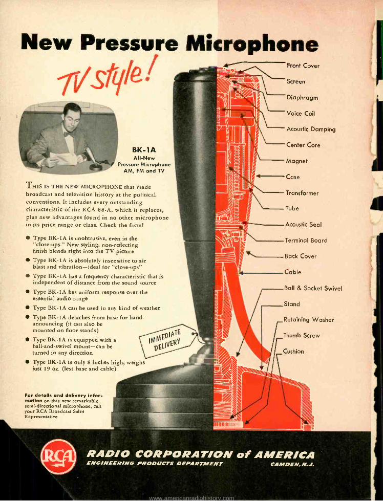
New Pressure Microphone f I Screen
Front Cover
BK -1A All -New
Pressure Microphone AM, FM and TV
THIS IS THE NEW MICROPHONE that made broadcast and television history at the political conventions. It includes every outstanding characteristic of the RCA 88 -A, which it replaces, plus new advantages found in no other microphone in its price range or class. Check the facts!
Type BK -1A is unobtrusive, even in the "close- ups." New styling, non -reflecting finish blends right into the TV picture Type BK -lA is absolutely insensitive to air blast and vibration -ideal for "close -ups"
Type BK -1A has a frequency characteristic that is independent of distance from the sound source Type BK -1A has uniform response over the essential audio range
Type BK -lA can be used in any kind of weather
Type BK -lA detaches from base for hand - announcing (it can also be mounted on floor stands)
Type BK -IA is equipped with a ball- and -swivel mount -can be turned in any direction
Type BK -lA is only 8 inches high; weighs just 19 oz. (less base and cable)
Diaphragm
Voice Coil
Acoustic Damping
Center Core
Magnet
4 Case
Transformer
Tube
Acoustic Seal
Terminal Board /1_ Back Cover
Cable
Ball & Socket Swivel
Stand
Retaining Washer
Thumb Screw
Cushion
For details and delivery Infor- mation on this new remarkable semi -directional microphone, call your RCA Broadcast Sales Representative
IIIIIIIIIIIIIIIIV
RADIO CORPORATION of AMERICA ENG /NEER /NG PRODUCTS DEPARTMENT CAMDEN, N.J.
www.americanradiohistory.com

NEW LITERATURE Peerless Electrical Products Division
of Altec Lansing Corporation, 9356 Santa Monica Blvd., Beverly Hills, Calif., re- cently released a new 15 -page trans- former catalog which contains 50 per cent more product listings than the last previous issue. Also shown and described are the company's facilities for design and manufacture of Class A, B, and H transformers built to military specifica- tions. Ava ilable on request.
General Electric Company, Schenectady 5 N. Y c ., describes the basic characteris- tics and applications of copper -oxide rec- tifier stacks in a new two -color 8 -page booklet designated GEA- 5699A. Remark- ably complete, the booklet contains charts, graphs, and tables which illus- trate the characteristics, manufacture, circuit design, and function of copper ox- ide rectifiers.
DeMornay- Bonardi, Inc., 3223 Buton Ave., Burbank, Calif., is now distributing a 134 -page catalog which combines list- ings of the company's microwave prod- ucts with a great deal of worthwhile tech- nical information on microwave engineer- ing. Opening pages of the book graphically explain the basic concepts of microwave communication. Included are graphs, charts and drawings.
Communication Products Company, Ina., Marlboro, N. .1., describes electrical and chemical properties of Q -max lac- quer and cement in Bulletin 752, which will be mailed on request. Included are the results of studies which will be of exceptional interest to all engineers whose work calls for the use of viscous insulating solutions.
Stevens- Arnold, Inc., 22 Elkins St., South Boston 27, Mass., illustrates and describes a new line of d.c. -a.c. choppers in catalog sheet 280B which will be mailed on request. Choppers shown have a 10-500 cps frequency range, are equipped with gold contacts, and have a life rating based on 11/2- volt -d.c. 1 -ma contact operation. All ratings are nominal and may be exceeded by as much as 50 per cent without damage.
Tech Laboratories, Inc., Palisades Park, N. J., has just issued a new 38 -page cata- log describing the complete line of pre- cision electrical resistance instruments and electronic devices as currently manu- factured. The catalog is bound in a hand- some loose -leaf folder, and describes at- tenuators, T -pads, potentiometers, match- ing networks, and gain sets, together with a number of measuring instruments useful in a communications laboratory. Copies will be furnished without charge to interested readers writing on com- pany letterhead.
Bausch St Lomb Optical Co., 650 St. Paul Street, Rochester 2, N. Y., offers a brochure on optical instruments for qual- ity control. This eight -page booklet is illustrated with photographs, drawings, and technical data, and describes the use of contour measuring projectors, stereo - microscopes, toolmaker's microscopes, thickness gages, and other optical instru- ments that may be used as separate units or built into present equipment for rapid inspection and measurement of a multitude of tooling and production items. Copies may be obtained without charge by requesting Catalog D -22.
Aircraft -Marine Products, Inc., 2100 Paxton Street, Harrisburg, Pa. offers two new illustrated booklets which pre- sent the highlights of the industrial films "All's Well That Ends Well" and "By the Millions." These pocket -size books are intended primarily for distribution to audiences preceding the showing of the films, but they are also useful and in- structive in their own right. The first of these films demonstrates the use and application of solderless terminals with precision hand tools, and the second shows how solderless terminals in strips fed from reels can be applied to wire at rates up to 4000 per hour with automatic machines. Both the booklets and the films were prepared for distribution and presentation before meetings of scientific and technical societies, trade associa- tions, industrial groups, and engineering and technical schools, as well as for customers and prospects. Requests for copies of the booklets and for further de- tails regarding the films will receive prompt attention.
to the
ELECTRICAL
ENGINEER
or
PHYSICIST
with experience in
RADAR
AUDIO ENGINEERING DECEMBER,
or
ELECTRON ICS
Hughes Research and Develop- ment Laboratories, one of the nation's leading electronics organizations, are now creating a number of new openings in an important phase of their operations.
Here is what one of these positions offers you:
THE COMPANY
Hughes Research and De- velopment Laboratories, located in Southern Califor- nia, are presently engaged in the development and production of advanced radar systems, electronic computers and guided missiles.
THE NEW OPENINGS The positions are for men who will serve as technical advisors to government agencies and companies purchasing Hughes equip- ment -also as technical con- sultants with engineers of other companies working on associated equipment. Your specific job would be essentially to help insure successful operation of Hughes equipment in the field.
1952
HUGHES
THE TRAINING On joining our organiza- tion, you will work in the Laboratories for several months to become thor- oughly familiar with the equipment which you will later help users to under- stand and properly employ. If you have already had radar or electronics experi- ence, you will find this knowledge helpful in your new work.
WHERE YOU WORK After your period of train - ing-at full pay -you may (1) remain with the Labor- atories in Southern Califor- nia in an instructive or administrative capacity, (2) become the Hughes repre- sentative at a company where our equipment is be- ing installed, or (3) be the
Hughes representative at a military base in this coun- try or overseas (single men only). Compensation is made for traveling and moving household effects, and married men keep their families with them at all times.
YOUR FUTURE
In one of these positions you will gain all- around ex- perience that will increase your value to our organiza- tion as it further expands in the field of electronics. The next few years are certain to see large -scale commercial employment of electronic systems. Your training in and familiarity with the most advanced electronic techniques now will qualify you for even more impor- tant future positions.
How to apply:
RESEARCH AND DEVELOPMENT LABORATORIES
Engineering Personnel Department Culver City, Los Angeles County, California
If you are under thirty -five years of age, and if you have an E.E. or Physics degree, write to the Laboratories, giving resumé of your experience.
Assurance is required that relocation of the applicant will not cause disruption of an urgent military project.
9
www.americanradiohistory.com
EDITOR'S REPORT
EXHALE TIIE FOURTH AUDIO FAIR has come and gone, and those of us who were there throughout the four days can finally take a breather. With an attendance of
slightly over 13,000 people -many of whom were there two, three, or even all four days of the show -there was anything but calm and quiet in the exhibit rooms and corridors of Hotel New Yorker. But we loved every minute of it.
We are pleased to note that a great number of the exhibitors reduced demonstration volume to levels which were more in keeping with that at which the average listener would employ in his own home. We also noticed that the disparity between the most elabo- rate systems and the more modest ones is less apparent than it was in past years, especially with average pro- gram material. When particularly fine program mate- rial was used, the differences were still noticeable.
The Audio Fair idea is certainly established as the logical method of demonstrating audio equipment - where sound is as important as sight. With this year's attendance exceeding 1951's by nearly 5000, the New York event may well be said to have "arrived."
Closely following on its heels will be the Audio Fair - Los Angeles, which takes place on February 5. 6, and 7 at the Alexandria Hotel in the City of the Angels. In some respects the Alexandria will be better than the New Yorker -its rooms are larger and the ceilings are higher. We are certain, however, that -better or only just as good -the Audio Fair -Los Angeles will be well attended, and will bring new interest in audio to the Pacific Coasters.
LOUDNESS CONTROLS The time has come to discuss one feature of the loud-
ness control that seems to have escaped general notice. A study of the Fletcher- Munson equal loudness contours will show that the ear is less sensitive to frequencies above about 3000 cps than over the range from 1000 to 3000, and that the curves for all levels are almost identi- cal above this point. Some loudness controls have been proposed which correct progressively for this deficiency, on the assumption that as over -all level is lowered, the high frequencies should be increased in addition to the lows.
May we point out that the human ear is less sensitive to these high frequencies at all levels, and that it is with these same ears that we listen to live music. Thus if the music is reproduced with a flat system (above 3000 cps)
it should be presented to the ear just as it is frein a live source, since the F -M curves are almost exactly the same in the high -frequency range. We submit, therefore, that no correction should be applied to the loudness control except that for the low frequencies.
This observation is addressed to those who go for the idea of the loudness control, and may be overlooked by those Who do not. However, we still prefer them.
AT LAST-THE R -) STORY In last December's issue, we carried a story about the
R -J speaker, but offered no constructional information. Since that time, the unit has become commercially avail- able and because of this we have been unable to offer any further information -particularly regarding its construction. This is a matter which has caused some concern among several hundred of Æ's readers -as well as among our own staff.
We are firmly assured, however, that we will have the R -J story in time for the January issue, and we know that many of you will he pleased at this news. In fact, we are extremely pleased ourselves to be able to get off the hook on this particular subject. So look for a thorough exposition of the R -J speaker next month, in an article by William Joseph and Frank Robbins.
SUBSCRIBE BUST ONCE MORE - IF YOU WISH
Over a lunch at the Audio Fair, it was suggested that we should offer Life Subscriptions so that Æ's readers could avoid the necessity of renewing their subscriptions every so often. The first person we encountered after the discussion jumped at the chance, and while he was putting down his name, another joined up, followed shortly thereafter by a third "lifer." Since this idea seemed to be snowballing, a conference was deemed necessary with the Business Manager -who, after all, has to make ends meet each month -with the result that those of you who like 2E can now take advantage of this opportunity. For further details, we respectively refer you to the top of page 44. But before you turn the page, the Editors and Staff of Audio Engineering wish you
A Rierrg Pristmtts nub
A 1qElpjJ1J NPllt Drat-
10 AUDIO ENGINEERING DECEMBER, 1952
www.americanradiohistory.com

... it comes to you in the subtle shading of a piano .. .
in the clean brilliance of violins, the purity of a flute. Your ear detects
the sweet mellowness of cellos,
the roundness of a clarinet .. yes, even the iridescense of clashing cymbals.
And, as the symphony swells to crescendo. its dynamic energy adds a flood of color
to your musical canvas.
For those who can hear the difference. these are the elusive pleasures
that often remain hidden in the grooves of fine recordings.
These are the thrilling new listening experiences
that are released for your enjoyment when you use quality components by Pickering.
PICKERING COMPONENTS
.,14 G/r.oae ce/ao cal? ate aeheince
P I C K E R I N G and company, incorporated
Pickering High Fidelity Components are available through leading Radio Parts dis-
tributors everywhere; detailed literature sent upon request. Address Department A 1
Oceanside, L. I., New York I III IIIIIII AUDIO ENGINEERING DECEMBER, 1952 11
www.americanradiohistory.com

The Triad "HS" and "HSM" Series of hermetically sealed transform- ers are particularly applicable to military and commercial uses, where long life and top perform- ance are prime factors. Because they are designed to meet MIL-T-27 specifications, their use in proto- types will eliminate redesign at the production stage.
Such features as "Climatite" Treatment, Wide Frequency Range. Reduced Field Pickup, Small Size, Low Distortion, Low Temperature Rise, Sturdy Terminals and Attrac- tive Grey Finish, make these trans- formers the obvious choice for all high quality electronic equipment.
Offered as a complete line in matching construction, Triad "HS" and "HSM" Series Transformers are available at all Triad jobbers.
Write for Catalog TR-52F
4055 Redwood Avenue
Venice, California
12
AES Views Society Announces Award Winners, 24 Fellowships, 21 Sustaining Members
DURING THE EXTREMELY successful Fourth Annual Convention, held at Hotel New Yorker from October 29
to November 1 inclusive, the Audio En- gineering Society announced the winners of the two annual awards -the Society's Award for outstanding service to the or- ganization, and the John H. Potts Award for outstanding achievement in the field of audio engineering -and also made pub- ic the names of the twenty -four Fellow awards and twenty -one Sustaining Mem- berships.
The Society's Award was presented to Ralph A. Schlegel, the citation reading "for his devotion and efforts in originat- ing and carrying on the important work of the office of Treasurer." Mr. Schlegel was first elected to the office of treasurer in 1948, and has served continuously since that time. The award, in the form of a certificate, was presented at the Annual Banquet of the Society, held on the eve- ning of October 30, at which Harold Burris -Meyer was toastmaster.
Also announced at the same time was the winner of the John H. Potts Memorial Award, which is given annually in the form of a plastic -embedded medal. This award was given "to Frank L. Capps, post- humously, for development and manufac- ture of high -quality sapphire recording styli. This award is double earned because his daughter, Isabel Capps, who receives it, has carried on his work and has herself made many valuable contributions to this art." Miss Capps, herself a member of the Society since its formation, accepted the medal and citation, both of which were presented by John D. Colvin, a member of the Awards Committee who acted on be- half of Chester A. Rackey, committee chairman, who was on the Pacific Coast on business.
Fellow Awards
The list of Fellows created at the Con- vention is as follows :
W. LINDSAY BLACK, for his work in broadcast audio transmission systems, standards, and measuring techniques.
H. BURRIS- MEYER, for his work in the ap- plication of audio sound effects in the- atrical production.
ISABEL CAPPS, for her work in develop- ment and manufacture of high -quality recording styli.
JAMES Y. DUNBAR, for his work in design of acoustic treatment, soundproofing, and vibration control.
PRICE E. FISH, for his work in the appli- cation of magnetic tape recording to radio broadcasting.
ERNEST W. FRANCK, for his work in the development of high -quality lacquer re- cording blanks and magnetic tape.
LEWIS S. GOODFRIEND, for pioneering in
development of audio engineering courses and for his work on artificial reverber- ation.
JOHN K. HILLARD, for his work in film recording and reproduction and for development of intermodulation testing techniques in film recording.
WILLIAM F. JORDAN, for his pioneering and continued activity in newsreel recording operations.
SAMUEL F. LYBARGER, for his work in de- velopment and standardization of hearing aids.
JOHN T. MuLux, for his work in promo- tion, development, and practical applica- tion of magnetic tape recording.
DR. HARRY F. OLSON, for his extensive research and development in the fields of acoustics and audio engineering, and for authorship of leading texts on these subjects.
NORMAN C. PICKERING, for his work in development and manufacture of high - quality disc reproducing equipment and for investigation in intermodulation test- ing.
JOHN PRESTON, for his work in research and development of microphones and loudspeakers.
ALBERT A. PULLEY, for his work in develop- ment and practical application of com- mercial recording and pre- processing techniques.
RICHARD H. RANGER, for his work in the general field of audio engineering and the development and design of magnetic tape recorders.
HILLEL I. REISKIND, for his work in devel- opment and design in the general field of disc recording and production processing.
CARLETON R. SAWYER, for his work in development of film, disc, and magnetic tape recording systems.
HERMON H. Scorr, for his work in devel- opment and manufacture of sound level meters and audio noise suppressors.
J. P. SMITH, JR., for his work in design and development of audio attenuators and measuring equipment.
S. EDWARD SORENSEN, for his work in system design in disc and magnetic tape recording.
W. EARL STEWART, for his work in design of commercial high -quality audio equip- ment and systems.
MYRON J. STOLAROFF, for his work in de- velopment and design of high -quality magnetic tape recording equipment.
WILLIAM J. TEMPLE, for his work in the science of speech.
Sustaining Members
During the past year, a number of manu- facturers and distributor's have contributed substantial sums to forward the work of
[Continued on page 51]
AUDIO ENGINEERING DECEMBER, 1952
www.americanradiohistory.com

11,
CI
DANCE STUDIOS
strikes a NEW NOTE in continuous
performance playback music
STEAMSHIPS
INTRODUCING THE
. " ]t! AMUSEMENT PARKS AND
RECREATION CENTERS
AMP F4X 45 II Up to eight hours of uninterrupted performance - day after day, year after year Requires no attention during operation Lowest cost per hour
The new AMPEX 450 gives you hours of high -quality back- ground music delivered at lowest cost per hour of any musical reproduction system. With the AMPEX there are no inter- ruptions, no records to change and no attendants since it needs no attention during operation. It plays at the touch of a button and keeps on playing for as long as eight hours without repeti- tion. Because tape doesn't lose quality with repeated playings, music is always scratch -free and pleasant, with less back- ground noise and distortion. The Model 450 is engineered to rigid AMPEX standards and is capable of delivering thousands of hours of service with no breakdowns and minimum maintenance.
For further information, write to Dept. B
IF YOU PLAN FOR TOMORROW, BUY AN AMPEX TODAY
Model 450 rack -mounted. Also available in portable or console mount.
FEATURES 50 to 7500 -cycle frequency response at 33/4 inch tape speed Standard NARTB reels up to 14 inches
Pushbutton controls Automatic reverse control available as an accessory permits full eight hour program without interruption.
AMP MAGNETIC RECORDERS
AMPEX ELECTRIC CORPORATION 934 C1 ARTER STREET REDWOOD CITY, CALIF.
AUDIO ENGINEERING DECEMBER, 1952 13
www.americanradiohistory.com

It splits seconds even faster
IN A split second, relays, which are high -speed switches, set up dial tele- phone connections. Then they are off to direct the next call. Yet even this speed is too slow for Bell Lab- oratories scientists in quest of still faster switching.
Scientists and engineers devised a new relay - the wire spring relay - and worked out the production prob- lem with Western Electric, manufac-
turing unit of the Bell System. This is twice as fast, uses less power and costs less to make and maintain.
With speedier relays, switching can be done with less equipment . .. and calls go through faster. The wire spring relay is a practical example of how Bell Telephone Laboratories and Western Electric pool their skills to improve telephone service while keep- ing its cost down.
New wire spring relay. Older relays had flat metal springs and 70 parts to be handled. com- pared with 12 in the now model. Relays operate by means of an electromagnet which responds to high -speed pulses.
New relays must be able to operate one billion times -equal to once -a- second for 30 years. Employing a sound recorder as a precision vibrator, Bell scientists learned to evaluate the effect of sideways motion on relay life. Such rubbing motion is limited to one -thousandth of an inch in the new relays.
Bell Telephone
Laboratories
Dynamic Fluxmeter, developed by Bell Laboratories, indicates flux build -up in intervals of 25 millionths of a second. Precise information like this was essen- tial to higher speed operation.
Relay springs as they come from Western Electric molding machine, before being cut apart for use.
Molding technique saves time and money ... makes possible the maintenance of precise adjustment.
IMPROVING TELEPHONE SERVICE FOR
AMERICA PROVIDES CAREERS FOR CREATIVE
MEN IN SCIENTIFIC AND TECHNICAL FIELDS
14 AUDIO ENGINEERING DECEMBER, 1952
www.americanradiohistory.com

Nominating Convention Organ Installation
SERGE L. KRAUSS & KARL KRAMER
Providing a high -power organ installation to be used only for two weeks presents some rather unusual
engineering problems -which were solved readily by use of electronic and electro- acoustical equipment.
THE PRODUCTION OF MUSIC for large audiences has been greatly facilitated by the development of the modern
electronic organ and wide- range, high - efficiency loudspeakers. The Connsonata organ installation for the recent presi- dential nominating conventions in Chi- cago is an excellent example of the type of performance that can be attained with this combination.
The International Amphitheater, site of the conventions, had no organ of any kind, and the Connsonata was selected to fill the need for this traditional type of music. The auditorium capacity is twelve thousand people; in addition to the per- manent seating space (main floor and balcony) there is a clear central floor space (arena) 123 by 236 feet that was used for the main speakers' platform. press, and delegate seating. The clear height over this space is 73 feet. It was apparent that in order to dominate, sup- plement, or over -ride with music the "noise" level occasioned by the custom- ary enthusiatic demonstrations of so
many people in so large a room, con- siderable undistorted acoustic power would be required.
The temporary installation on short notice of a pipe organ with sufficient power for this purpose would have in- deed been an enormous project. The single problem of space for such an organ would probably have precluded its use. In contrast to this possibility was the use of a modern, flexible and easily portable electronic organ, with its tone generators enclosed in the organ console and with only loudspeakers and their as- sociated amplifiers as additional equip- ment for meeting the requirements of the large auditorium.
The floor space allotted for the in- stallation of the organ console and bench and the speaker amplifiers was limited to less than 45 square feet. It is inter- esting to note that there was room enough left over in this small space for a number of chairs. The reproducer as- semblies were suspended front the ceil- ing in the middle of the auditorium and did not detract from the seating ca- pacity.
The Connsonata used was a standard stock model 2C2 with separate manual
W Design Engineer. Electronics Division C. G. Conn, Ltd.. Elkhart, Indiana.
ss Technical Service Manager, Jensen Manufacturing Company, Chicago, Illinois.
S - SWELL MANUAL REPRODUCER G -GREAT MANUAL REPRODUCER P. PEDAL REPRODUCER
BROADCAST BOOTH AND SPEAKERS PLATFORM
Fig. 1. Plan of the reproducer gondola showing the arrangement of the various speakers.
and pedal audio channels; the specifica- tions are given in Table 1. Independent channels are advantageous in that the speakers can be designed for maximum efficiency in the spectrum covered. The pedal tone spectrum is from 32 to a few thousand cps and each manual spectrum is from 64 to above 12,000 cps. Having a separate pedal channel avoids the ap- plication of tones in the octave from 32
Fig. 3. Tr:axial unitary 3- channel loudspeaker system.
to 64 cps on the manual speakers and thus keeps the "Doppler" distortion at a
minimum. With independent manual channels the amplifier -reproducer equip- ment can be dwwided in proportion to the sound power necessary for the desired musical balance for the type of music played. It is also possible, with separate manual channels, to provide an effective echo organ feature by switching the
EXPRESSION TONE SOURCES CONTROL
AMPLIFTERS
60 WATT
TRIAXIAL SPEAKER
IN BACK-LOADING FOLDED HORNS
60 WATT O
SWELL MANUAL KEYBOARD TONE GE PERATOR SVOICE CON T ROLSE TC.
60 WATT ISOLATING
MPLIFER 60 WATT
e 60 WATT
I
60 WATT
I
GREAT MANUAL KEYBOARD. TONE GEMERATOSNOICE CONTROLSETC
60 WATT ,---0 I
ISOLATING
AMPLIF ER 60 WATT
WATT 60 60 WATT
PEGALBOARD TONE GENERATORS
30 WATT 30 WATT PEDAL HORNS
VOICE CONTROLS ETC.
E. 30 WATT ID' DRIVERS
30 WATT G
CONNSONATA MODEL 2C2
ORGAN CONSOLE
AUDIO ENGINEERING DECEMBER, 1952
Fig. 2. Block diagram of the complete organ reproducing system.
15
www.americanradiohistory.com

,,"',^
Fig. 4. Complete assembly of speaker unit in back -loading cabinet for use os manual re-
reproducer.
swell manual channel to reproducers lo- cated at a distance from the main re- producer.
The possible number of individual, non -interlocked fundamental tones pro- duced simultaneously by an organist on each playing manual exceeds 60. In ad- dition, many harmonics of these tones are present in the pulse (string) signals. The instantaneous peak power of such a complex signal is several times the aver- age power, so the amplifiers used must be capable of handling these high signal peaks without distortion. The amplifiers used for the convention installation were operated at approximately one third their normal continuous undistorted power output capacity. To keep the power requirements within bounds, effi- cient reproducers are essential for large installations.
The initial decision was to install the loudspeakers at the end of the audito- rium behind the speaker's platform and facing most of the audience. Installation of the radio- television control booth in this location prevented this and re- sulted in choice of a central location near the ceiling. The loudspeaker array is shown in Fig. 1. Six reproducers were assigned to the swell manual channel and four to the great manual channel. Each manual reproducer was excited by an amplifier of 60 -watt rating. The two pedal horns each had two driver units and each driver unit was excited by an amplifier of 30 -watt rating. A block di- agram of the installation is shown in Fig. 2.
The application of individual ampli- fiers for each reproducer allows the use of stock amplifiers with tube comple- ments that are readily obtainable. The maintenance of such a system is simple, for in case of a component failure only
16
Fig. 5. Specially constructed exponential horn used for the pedal reproducers.
a small fraction of the system is dis- abled and repairs can be made without disrupting the program. The reliability of the installation under discussion was proven in that no maintenance at all was required throughout the two strenuous sessions.
Interference with broadcast facilities was avoided by arranging the loud - speakers so that little sound energy was radiated directly toward the control booths. Conversely, the organ installa- tion was checked for possible influence from pack transmitters, television sig- nals, etc., and was found completely free from pickup.
Great and Swell Manual Reproducers
All ten of the reproducers assigned to the great and swell manuals were identi- cal multiple -channel loudspeaker sys- tems. Each was comprised of a Jensen G-610 Triaxial 3- channel unitary loud- speaker system' installed in a large back - loading folded horn.2 Figure 3 shows
the unitary loudspeaker system and Fig. 4 shows this Triaxial speaker installed in the horn to form the complete repro- ducer.
As the name implies, this type of horn loads the back of the 15 -inch direct - radiator diaphragm up to a frequency of about 300 cps. Above this point the horn radiation is negligible but radiation from the front of the same 15 -inch dia- phragm occurs with high efficiency. For frequencies above 600 cps the constant resistance dividing network diverts the electrical input to a compression -type
1 Karl Kramer, "A three -channel loud- speaker." FM -TV Radio Communication, Sept. 1951, p. 40.
2 "A back -loading folded horn for 15 -inch loudspeakers." Jensen Technical Bulletin No. 1, available without charge from Jen- sen Manufacturing Company, 6601 South Laramie Avenue, Chicago 38, Illinois.
[Continued on page 17]
Fig. 6 The reproducer gondola just before hoisting to its operating position.
AUDIO ENGINEERING DECEMBER, 1952
www.americanradiohistory.com

A Discussion of Dividing Networks
J. P. WENTWORTH
Presenting two simple dividing networks -one of which provides a connection point for negative voltage feedback which will equalize over -all amplifier- speaker response.
IT IS GENERALLY ACKNOWLEMEU that a single loudspeaker unit can not re- produce optimally the entire audible
frequency range. For clean reproduction of high -fidelity music, at least two speakers are required, each transducing signals in a limited frequency band. To insure that each speaker receives only signals within its own frequency range, it is customary to use a dividing network or networks to distribute the signal among the speakers.
Perhaps the neatest way to accomplish such signal distribution would be to separate the frequency bands at a low power level, and to use an individual power amplifier for each speaker. How- ever, since the output stage and trans- former represent a considerable part of a high -quality amplifier, in terms of cost, power consumption, and weight, it is usually more expedient to make the separation at the secondary side of the output transformer.
An ideal multispeaker system would give the impression that the sound emanated from a single super- speaker, which was able to handle all frequencies. To accomplish this aim. the dividing net- work should satisfy the following crite- ria :
1. The network must so distribute the signal among the speakers that the acous- tic power output at every frequency is the same as that radiated by the single hypo- thetical ideal speaker.
2. All frequencies should be radiated with the same phase relationships a, those that would exist in the case of the single ideal speaker. This objective is a rather minor consideration in minimizing phase distortion; however, if inverse feed back voltage is to be taken from the
2058 E. 81st St., Cleveland 3, Ohio.
Fig. 2. Circuit arrangement for obtaining feed back voltage from voice coils of two -speaker
system.
speaker voice coils, it becomes a re- quirement of paramount importance.
3. The speaker system should present to the amplifier a constant and purely re- sistive impedance, in order to minimize distortion in the output stage of the amp- lifier.
4. In the interest of economy of power, it is desirable that the network be non - dissipative; i.e., that it be made up of purely reactive impedance elements.
5. In order to provide effective damp-
[Continued on page 49]
INN C. T2nIrR L. 2R2C
tal
PLO',
SPEAKER VOICE COILS
Rnlam
C In farads L in harts. R in ohm.
vOICE COILS
C 2n1cR
2 L. 2nfe
R C
tel
Fig. 1. (A) Parallel network, constant resistance type, giving a cut -off slope of 12 db per octave; (B) Half- section network giving cut -off slope of 6 db per octave.
1,000 900 900 TOO
600
500
400
300
200
100 90 eo
To
60
50
a0-
30
20
10fß
1.
` \
N(--
á
c c %
41
+ y
- C - capoc I et n ieroleraa. - L- inducrpnc. 'n mlc ro Marto
R- In NSilene. ehm.
CIRCUIT A
CIRCUIT
NI
CROSS OVER FREQUENCY ,000
IN CYCLES PER SECOND
AUDIO ENGINEERING DECEMBER, 1952
Fig. 3. Chart for determining values for L and C in networks of Fig.
www.americanradiohistory.com

Simplified Equalizer Design GEORGE A. DOUGLAS
Charts and tables to reduce complication -and construction hints to ease building.
Ix applications requiring exact modi- fications of the audio spectrum, con- stant- resistance equalizers are capa-
ble of doing the job with maximum efficiency and convenience. The cor- rection of cutter peaks and tape droop at the high end, the incorporation of pre -emphasis, and numerous other alter- ations of response can readily be accom- plished with the design data that follows. and which involves only simple arithme- tic to calculate values of components; or, with the use of a reactance chart, a few steps of multiplication.
Figure 1 shows the four configura- tions with their transmission charac- teristics used to cope with the equalizer problems commonly met in audio work. The circuits of(a) and (b) are shelf suppressors, or conversely, low and high boost; (c) and (d) are peaking equalizers. As it is inadvisable to use
51 E. 42nd St., New York 17, N. Y.
more than 20 db of attenuation in a single equalizer, it will be seen that the shelf suppressors serve where a gradual curve is required not exceeding 6 db per octave. Networks may be cascaded to obtain a steeper characteristic, but
Fig. 2. Method of
adding pre- emphasis
to recording charac-
teristic to eliminate
a cutter peak, for
example. Curve A represents normal re-
sponse, while curve B
represents desired re-
sponse. The required
equalization is repre-
sented by the differ-
ence between the two
curves.
this requirement is usually met by ap- plying (c) or (d), in which case it is possible to control, the slope.
The first step in the design of an equalizer is to draw on logarithmic pa- per the actual and desired response of
MIM
A - NORMAL RESPONSE - nwAt, ZED POMPONS!
iu
e
NOW
IW
MOO
IN CYCLES PER SECOND
162
<
la) Ibl Ic) 1a1
1
I
I
I
i
I
I
I
MAX
,2
0
1 I
1
1
1
I
I
I
I
I
1
I
I
CI
Ir
L3
1
S C`
RI RI R2
C2
RI RI
R2
L2
RI R1
R2
LA
CO
Rr RI
R2
6
K_1 LI .-L r
K-1 :2 C { T
L2. L K
C I r C
K-I
K-1 b2-1 L3 f b2L
U 2 L K-1 b-1
C3{ C K-1 b-1
2
CO.K-1 -1G f b2
K-1 I LS ee_IL
T °e-1 L6 - L
K-1 b
T -1 CyK-1 -2-
C
C6.K-1 1 r b- 11
} Fret'. 1/2 Pad Loss
tr Fr.R. of R.sononc.
K All.nuatlon Factor
20109 K Pad Loos db 1r
Ro un. IInP.eonc.
159Ro
Mfd
f
159,000 C.
fRO
Fig. 1. Chart showing the configurations of four different types of equalizers. together with formulas for determining the reactive elements.
AUDIO ENGINEERING DECEMBER, 1952
www.americanradiohistory.com

the equipment requiring modification or correction. This will furnish informa- tion to construct the transmission char- acteristic of the equalizer. On this curve note the design frequency on the transmission characteristic at the line of half the total attenuation. With the design frequency f and the impedance of the line in which the equalizer is to work, calculate L and C, or take their values directly from a reactance chart. L, to L. and C, to Cs may now be as- certained by substituting in the equa- tions figures taken from the accompa- nying tables.
For the shelf suppressors only Table
1 is used. The values for- =1 and -- VK K -1
and for R, and R. for an impedance of 1 ohm, are located opposite the degree of attenuation desired. For other val- ues of R, and Rs, multiply by selected Rd. The data in Table 2 determines the slope of equalizers (c) and (d). The ratio in column 1 corresponds to fr /f (the resonant frequency divided by the frequency of one half the attenuation). Opposite this are found the solutions of b' -1
b, and l 1
Example:
Curve (A) of Fig. 2 depicts a typi- cal cutter response above 1000 cps. It is desired to design a 600 -ohm equal- izer for a recording characteristic with 10 db of pre- emphasis at 10,000 cps. Ordinarily the low- frequency shelf suppressor could be used, but in this case the cutter peak would be undesir- ably increased. It is apparent that the rising slope of the peak can be con- tinued to the 10,000 -cps, 10 -db point; therefore the obvious solution is to de- sign the equalizer with the configura- tion of (d) with a resonant frequency of 10,000 cps, and an attenuation' of 10 db. From the curve, the point of . half the attenuation, or 5 db, is found at 7000 cps, the design frequency. L and C can now be ascertained:
OSCILLATOR CI I Fig. 3. Crcuit arrangement for determinin
resonant frequency of LC combination.
' While the term "attenuation" usually refers to a loss, it has a slightly different meaning when used with an equalizer of any of these types. In the case of equal- izers (c) and (d), attenuation refers to the difference in the transmission at the resonant frequency to that at frequencies remote from the resonant frequency. For those equalizers of types (a) and (b), at- tenuation refers to the difference in trans- mission at the two extremes of the fre- quency spectrum. In both cases, this "at- tenuation" is determined by the loss in the resistive network, which is normally re- ferred to as an attenuator or pad.
L=159 000
600=13.62 Mh
C 159,000 _ 038 uf 7000 x 600 -' Now, since
K-1 1 L,-L- VK 10 -1 VK b=-1 L° L K-1 b!
C C /K bs -1
K-1 b!
K=1 1 C,-C VK bp -1
From the tables:
-- =1.213 VK
K -I VK= :824
R, = .520
R, _ .704
Substituting, we
Ír 10 f = 7
=.512 b4
1_ b` -1 =.952
now have:
Fig. 4. Two equalizers constructed by the author -left, a plug -in unit employing a fixed amount of equalization, and right, a unit pro-
viding step- switch control of attenuation.
for to some extent by including it in the pad. Thus, when an inductance ap- pears in the shunt arm, its d.c. resist- ance should be deducted from R,, and a resistor selected which has an actual
[Continued on page 51) TABLE 2
EQUALIZERS
L, = 13.62 x 1.213 x .952 = 15.7 Mh L,= 13.62 x .824 x .512 = 5.8 Mh Cs = .038x.824x.512= 0.16µf C, = .038 x 1.213 x .952 = .043 of R, _ .520 x 600 = 312 ohms R,= .704 x 600= 423 ohms For many applications in the upper
frequency range, r.f. chokes can be utilized, providing the d.c. resistance is not excessive. The photographs, Figs. 4 and 5, show a completed equalizer with 5 -mh. coils of about 15 ohms. To provide proper inductance, select ca- pacitor(s) of correct value for C in Fig. 3. Set the oscillator to the desired resonant frequency, with more induct- ance in the circuit than is needed, and remove turns until maximum attenua- tion occurs.
Coil resistance can be compensated TABLE
I b'
b'-1
10 .187 4.348 9 10
8 .359 1.785
10 512 .952 7
10 6 .637 .568
10 5
10
10
.750 .333
4 .840 .190
.910 .099 3
.960 042 10 2
EQUALIZERS
db K-1
VK V K
K-1 R Rz
1 .113 8.833 .057 8.68 2 .232 4.307 .114 4.32 3 .345 2.902 .171 2.84 4 .468 2.135 .226 2.20 5 .586 1.705 .280 I .646 6 .709 1.410 .332 1.34 7 .826 1.193 .382 1.118 8 .949 1.053 .430 .946 9 1.082 .923 .476 .812
10 1.213 .824 .520 .704 H 1 1 .356 .737 .560 .602 12 1.500 .667 .598 .536 13 1.644 .608 .634 .472 14 1.790 .558 .668 416 15 1.949 .513 .700 .368 16 2.116 .453 .728 .310 17 2.285 .437 .752 .268 18 2.461 .406 .776 .246 19 2.654 .376 .798 .224 20 2.848 .351 .818 .202
AUDIO ENGINEERING DECEMBER, 1952
www.americanradiohistory.com

Handbook of Sound Reproduction
EDGAR M. VILLCHUR
Chapter 7- History of the Phonograph
The recording of sound has been of interest to inventors for nearly a
hundred and fifty years, although means of reproducing it is only seventy - five years old. Some of the earliest instruments are described by the author.
IN 1877 THOMAS Entsov, for the first time in history, succeeded in repro- ducing sound mechanically from a
recorded pattern. The inventor played back his own recitation of Mary Had a Little Lamb on an instrument that was
Contributing Editor, Aumo ENGINEER- .' NC.
Fig. 7 -1. Young's sound recorder and chron- ometer of 1806 (from a copper engraving of that dote). The original caption reads: "The axis AB being turned, either by the handle A or by the weight C, the balls D, E, fly out, and carry the weights, F, G, further from the axis; in consequence of which the increased effect of friction retards the motion when it becomes too rapid. The barrel H is turned in the meantime, with the axis, and is allowed to descend as the thread at I is uncoiled, so
that the point K, which is pressed against it by
a spring, describes on it a spiral, which is in- terrupted whenever the pin K, is touched."
From: A Course of Lectures on Natural Phi- losophy and the Mechanical Arts, 1807.
ingeniously conceived, but which was largely modeled on a basic earlier de- sign, one that had been used in sound recorders over a period of seventy years.
Thomas Young, the British physicist who introduced the modulus of elasticity in current use, described a device in 1806 which was able to make a graphic record of sound waves. The vibratory nature of sound was known, and the use of a time vs. pressure graph to rep- resent sound vibrations was familiar to workers in acoustics. This device made such a graphic record automati- cally; the stylus was actuated by the sound itself rather than by the hand of a draftsman.
Young's description of the principle of sound recording is as clear and valid today as it was then, and it may serve us here:
"The situation of a particle at any time may be represented by supposing it to mark its path, on a surface sliding uniformly along in transverse direction. Thus if we fix a small pencil in a vi- brating rod, and draw a sheet of paper along, against the point of the pencil. an undulated line will be marked on the paper, and will correctly represent the progress of the vibration."
The recorder in which this principle was first applied is illustrated in Fig. 7 -1, a reproduction of the original copper engraving in the 1807 edition of Young's "A Course of Lectures on Natural Philosophy and the Mechanical Arts." The recording stylus K, which was held pressed against the cylinder by spring tension, had to be touched by a "sounding body" in order to have vibrations induced in it. The traced line or groove was varied transversely rather than in depth ; this is the type of recording known today as lateral.
Sound recorders were constructed by several other experimenters, such as Duhamel and Wertheim, during the first half of the 19th century. All of these devices, like the apparatus illus- trated in Fig. 7 -2, required direct con- nection between the source of sound and the recording stylus. The immediate ancestor of the modern phonograph is therefore considered to he the instru- ment built in 1856 by Léon Scott de Martinville, whose recorder was the first to receive its energy through acoustical rather than mechanical coup- ling to the source.
Sound to be recorded on Scott's in- strument was directed through a horn
Fig. 7 -2. Early experiments in sound recording. No intermediary diaphragm was employed, as
in the phonautograph, between the source of sound and the recording stylus. From: Telephones
et Phonographes, Alfred Niaudet, 1878.
AUDIO ENGINEERING DECEMBER, 1952
1
www.americanradiohistory.com

against a parchment diaphragm and at- tached hog -bristle stylus. The point of the stylus pressed against a cylindrical surface treated with lampblack, so that the path of displacement produced by stylus vibrations was scratched into the lampblack, revealing the white paper Underneath. The traced line was made to travel along the time axis of the graph by continuous rotation of the cylinder past the point of stylus con- tact, and a feed screw moved the cylinder longitudinally, creating a heli- cal rather than a circular trace.
This device was called, appropriately, the phonautograph, from phone (sound), and autograph (self- writing). It was manufactured commercially by the Paris firm of Koenig as a laboratory instrument for measuring and record- ing, a mechanical oscilloscope. (See Fig. 7 -3). The translation of acous- tic vibrations into a frozen engraving of their wave forms thus ceased to be a purely experimental technique. Within its limitations the phonauto- graph could capture the characteristics of frequency, overtone structure, and dynamic range of any given group of sounds. There remained only the final step of devising a method to recall the sound from its symbolic state.
The process of recall had to reverse the recording sequence exactly, that is, to produce mechanical and then acous- tical vibration by dragging a compliant stylus through a rigidly engraved graph of recorded sound. The stylus would then be forced to vibrate in a similar manner to the recording stylus which had received the original sound energy, and imitative acoustic waves could be set up through an attached reproducing diaphragm. Scott predicted that the clay would come when recorded sound could be re- created, but it was more than twenty years before an instrument of recall was built. Although the prin- ciple was known, the quantitative prob- lem of creating a groove rigid and deep
enough to direct the motion of a repro- ducing stylus had to be solved.
Strange as it may seem, "talking machines" already existed; these were pneumatic devices designed to produce intelligible speech rather than musical tones. The keyboard controlled speech organ (Fig. 7 -4) constructed by Josef Faber of Vienna was considered the most perfect of the robots. It could be made to speak by 'means of a com- plicated and ingenious mechanism, arti- ficial vocal apparatus consisting of bellows, valves, adjustable air cavities, a little fan wheel to roll its r's, and rub- ber lips and tongue. Such devices, mechanical forerunners of the modern electronic voder, were the outcome of a different branch of acoustical research than Scott's, but they probably stimu- lated thought in terms of sound repro- duction.
A machine to perform the reversal of Scott's recording process was sug- gested by several writers in periodical literature, and in April, 1877, Charles Cros deposited with the French Acad- emy of Sciences a sealed packet con- taining the description of a complete reproducing system. Cros planned to make metal records of phonautograms by photo -engraving after the lampblack groove had been traced.'
The first working model of a sound reproducing machine, however, was made in the laboratory of Thomas Edi- son later that year. Edison drew up the plans shown in Fig. 7 -5 and assigned a worker in his laboratory, John Kruesi, to build a "phonograph" within a bud- get of eighteen dollars. Like Cros, Edi-
t (Translated excerpt from Cros' paper) "Speaking generally, my process consists in obtaining traces of the movement to and fro of a vibrating membrane, and in using this tracing to reproduce the same move- ment, with its intrinsic relations of duration and intensity, either on the same membrane, or on one adapted to give out the sounds which result from this series of movements.
V Z (-1-1
AUDIO ENGINEERING DECEMBER, 1952
Fig. 7 -5. Edison's original working sketches for the phonograph. From: The Life and Inventions of Thomas Alva
Edison, by Dickson, 1894.
Fig. 7 -3. The phonoutograph of Leon Scott de Martinville. (Courtesy The Smithsonian Insti-
tution).
son realized that the engraving had to be stiff enough to force the stylus to fol- low the recorded convolutions. He solved this problem by producing a deep embossing in tinfoil, a medium with a compromise degree of hardness. The embossing stylus was mounted so that it could indent, in varying degree, a sheet of tinfoil wrapped on a pre - grooved brass cylinder. The depressions of the cylinder's threads accepted the indented material, and although each playback deformed the shape of the groove, enough of the original form was retained to reproduce speech intel- ligibly. This retention was made pos- sible by the very poor efficiency of re-
"It is therefore necessary that an ex- tremely delicate tracing, such as may be ob- tained by passing a needle over a surface blackened by fire, should be transformed into a tracing, capable of sufficient resist- ance to guide an index which will transmit its movements to the membrane of sound.
. . By a well -known photographic process, a transparent tracing of the modu- lations of the spiral can be represented by a line of similar dimensions on some re- sisting substance -tempered steel, for ex- ample... .
Fig. 7 -4. The Faber speech organ. speech could be "played" from the in front of the bellows. From: li Zeitschrift fur Allgemeine Sprach
1884.
www.americanradiohistory.com

production; the resistance presented by the playback stylus was far less than the original recording force.
The phonograph was demonstrated before various scientific groups. When, in 1878, it was presented at the Aca- démie des Sciences, it was received by several members with suspicion, and the suggestion was even made that the operator of the machine seemed to be "grimacing" like a ventriloquist. One Academy member who was more real- istic remarked that Edison's invention. while valid, consisted of the sheet of tinfoil. In any case the use of a record- ing medium with an in- between degree of hardness was a successful but inef- ficient solution to the problem of re- production. Charles Tainter and Chi- chester Bell (a cousin of Alexander G.) took out a patent in 1886 which cor- rected this feature and which went a long way towards making the phono- graph practical. Embossing was dis- carded for cutting (the recording stylus was given a sharp edge), and the record was protected from damage during playback by the rounded shape of the reproducing stylus tip.
Commercial Development of the Phonograph
During the next few years recording was advanced to a point where it could be exploited commercially. At first the reproduction of sound found its main application in office dictating machines. Edison himself listed the reproduction of music only fifth in a tabulation of proposed uses, with the recording of family records and "the last words of dying persons" a close sixth. An 1892 phonograph instruction manual showed various models of industrial cylinder recorders being manufactured, differ- ing mainly in the type of motive power used. They were driven by treadles, water motors that worked through con- nection to the faucet, or electric motors, both battery and line operated, as pic- tured in Fig. 7 -7. All of these systems were later superseded by the governor controlled spring motor, which was adopted almost universally for both office and home machines until the house current motor was revived.
Record players were quite expensive, too costly for the ordinary home. Ma- chines for entertainment were provided in coin -operated public phonographs which would play a selection into one or more stethoscope -type hearing pieces «r through a horn. Records had to be
Fig. 7 -8. A 1900 juke- box -the Edison "Hydra - Phonograph,' a six -cylinder coin -operated player. From: L ^.lodernen Sprechmaschinen.
changed manually, but the modern rec- ord changer was foreshadowed by a repeating mechanism that brought the reproducer back to the start of the record and started the needle in the grooves automatically. A dealer trade magazine, The Phonogram, warned that the success of talking machines in the entertainment field was ephemeral, and might be bad for the growth of the phonograph industry. An editorial in this periodical stated, in 1891:
"There is danger of too much attention being given . . to the 'coin -in- the -slot' device (Fig. 7-8) at the expense of the more legitimate business of the companies, of introducing the phonograph into gen- eral use among business men. The ex hibition of the phonograph for amuse- ment purposes ... is calculated to in- jure the phonograph in the opinion of
Fig. 7 -7. Three commercial products of the 1890's. Left to right, the Tainter treadle Grapho- phone, the water -motor Edison Phonograph, and the electric Edison Phonograph, available for battery use or "wound for the incandescent current." From: A Short History of the Talking, Machine Industry, Columbia Graphophone Company, 1913; The Phonograph and How to Usc
It, National Phonograph Company, 1900; and Die Modernen Sprechmaschinen, 1902.
AUDIO
these seeing it only in that form, as it has the appearance of being nothing more than a mere toy, and no one would com- prehend its value or appreciate its utility...." But despite the editors of The Phono-
gram, and also despite the recrimina- tions and patent suits and countersuits that raged among manufacturers, the phonograph emerged as a popular in- strument whose main function was entertainment in the home.
Techniques for the mass production of records from a single master mold, developed by Emil Berliner (who started his researches by successfully carrying out the proposals of Cros) made records for home entertainment possible, and in addition introduced problems of standardization which had not existed when the same machine did both the recording and the reproduction. Early record buyers had to be advised, for example, to adjust the motor speed during the opening announcement until "the tones of voice seem to be in a natural key, and neither too high and shrill nor too low and heavy."
It did not take long for manufacturers to achieve mechanical excellence and reasonable cost in their record players. An Edison phonograph at the turn of the century was a nickel -plated joy to behold, well designed and rugged.2 The pickup, then called a speaker, produced only a small fraction of an ounce pres- sure on the cylinder groove, and had a permanent sapphire needle mounted in it. (See Fig. 7 -9) The quality of the reproduced sound, however, was very poor. Distortion was high, blasting occurred at those parts of the music which found sympathetic resonance in the reproducing apparatus, and fre- quency response -besides being very irregular -was so restricted that all fundamental tones represented by the lower half of a piano keyboard were missing, except as they could be detected by their harmonics. The ab- sence of bass, together with the severely limited volume, gave the sound the characteristic tinny quality associated with old players.
In an effort to obtain increased sound output, many unique systems were employed. Among them there was
[Continued on page 39]
2 Many are still in good playing condi- tion.
Fig. 7 -6. Edison disc phonograph. From: The falephone, the Microphone, and the Phono-
graph, 1879.
ENGINEERING DECEMBER, 1952
3
www.americanradiohistory.com

Speaker Treatment for Improved Bass
CAMERON BARRITT
A simple method of lowering the effective low- frequency limit of inexpen- sive speakers, but not one that is recommended for high -quality woofers.
ADESIRABLE FREW CENCY REJPUN SE
characteristic for an audio repro- ducing system requries adequate
lows as well as highs. Amplifiers are available which can handle the necessary range, but the loudspeaker is the bottle- neck in the drive toward more perfect audio reproduction. The problem of ren- dering sufficient highs can be met by various means such as the employment of "tweeters"-some of which can go close to the upper limit of human audibility - but the low- frequency speakers or "woofers" usually fall far short of the lower limit. Sound is propagated at fre- quencies as low as 16 cps, and 20 cps is usually considered as being audible. LP records are capable of going down to 30 cps, by way of further example, but not many speakers go this low.
The lower limit of a properly baffled speaker is determined by the mechanical resonant frequency of the vibrating pis- ton or cone. A çertain amount of propa- gation occurs below this frequency but response falls off rapidly beyond. The resonant frequency of a mechanical vi- brating system is determined by the mass and the compliance -the inverse of stiff- ness. These two are the electro- mechani- cal analogs of inductance and capaci- tance. The mechanical resonant fre- quency formula is f r =1 /2a./mC. The mass of a speaker cone is determined for the most part by constructional require- ments for rigidity, and is not readily altered. Furthermore, if one were to in- crease the mass very much in order to lower the resonant frequency, phase re- sponse would suffer and poor transient response might result. For best repro- duction of transients a low m/C ratio is required. On the other hand, the com- pliance of the speaker depends on the "give" in the cone suspension or mount- ing and no undersirable consequences will result frnm increasing its value.
1200 Susquehanna Ave., If. Pittston. Pa.
Fig. 3. Circuit arrangement used to determine resonant frequency of loudspeaker.
SUSPENSION COMPLIANCE
CONE MASS ACOUSTIC MP LOAD
ACOUSTIC CAPACITANCE OF CABINET
Fig. 1. Equivalent electrical circuit of a loud- speaker mounted in a baffle.
The total compliance or capacitance of the speaker system also depends on the acoustic capacitance of the air volume in the baffle if it is the totally enclosed type. The equivalent electrical circuit' of a loudspeaker mounted in an enclosed baffle is shown in Fig. 1. Notice that the two analogical capacitances are in series. If the baffle is made as large as possible, it will he so much larger a capacitance than the cone compliance that the limit- ing value will be in the suspension. The remaining reactance - the inductance representing the quadrature component of the speaker's air load -is usually small enough to be ignored (except in the case of the R -J speaker enclosure where it is exalted to make possible a smaller speaker enclosure). Consequently that
' Harry F. Olson, "Elements of Acousti- cal Engineering." McGraw -Hill.
Fig. 2. Method of slitting cone, as de- scribed by the author, and location of shel-
lac scaling ring.
AUDIO ENGINEERING DECEMBER, 1952
o
leaves just the cone suspension com- pliance on which to work in improving the bass range of a speaker.
Since the baffle is of no concern, one can use the "free -space resonant fre- quency" of the speaker as the working criterion. Although the mass of a speaker cone can not be controlled enough to vary this frequency very much, the cone suspension can be treated to make it more compliant and this would lower the resonant frequency the same as would increasing the capacitor in an electrical "tank" circuit. There are two methods of doing this, and by utilization of both it is possible to lower the frequency response limit 30 per cent or more. A relatively inexpensive 8 -inch speaker treated by this system can be made equal in bass -range capability to a good quality 12 -inch speaker.
Methods of Increasing Compliance
The first method is called "slotting" by the makers of Permoflux loudspeakers. As shown in Fig. 2, the speaker is made less stiff by radial incisions in the sus- pension. The improvement derived from this treatment depends on the merit of the suspension design beforehand. The suspension area of some good modern speakers is extremely thin, as can be
[Continued on page 54]
SLITS
23
www.americanradiohistory.com

AUDIO engineering society
P. O. Box 12, Old Chelsea Sta., New York 11, N. Y.
Containing the Activities and Papers of the Society, and pub- lished monthly as a part of AUDIO ENGINEERING Magazine
OFFICERS
F. Sumner Hall President W. S. Pritchard . Central Vice -Pres. Jerry B. Minter Executive Vice -Pres. R. L. Burgess .. Western Vice -Pres. C. J. LeBel . Secretary Ralph A. Schlegel Treasurer
Wide -Angle Dispersion
of High -Frequency Sound ABRAHAM B. COHEN
A description of the design of a series of high- frequency horns with improved per- formance in the horizontal plane and a minimum of diffraction in the vertical plane.
6:44
c1)0
Fig. 1. Two commercial horns which employ the reverse -flare principle described.
Summary: A high degree of wide -angle dispersion
in one plane may be achieved by means of a compound horn in which the primary section allows wave expansion only into the undesired plane. This creates a pres- sure gradient along the horn walls defin- ing the desired plane. The built up pres- sure is subsequently allowed to expand into the desired plane by reversal of the direction of flares of the horn walls. This reverse -flare device in conjunction with a square horn mouth provides wide -angle radiation free from phase cancellation and mouth diffraction effects.
rN ESSENTIAL REQUISITE of a tweeter adiator is that the high -frequency nergy be distributed over a wide
horizontal angle. Failure to attain such a characteristic results in off -axis loss of level of the high frequencies. How-
* University Loudspeakers, Inc., 80 S. Kensico Ave., White Plains, N. Y.
Responsibility for the contents of this paper rests upon the author, and state- ments contained herein are not binding upon the Audio Engineering Society.
24
ever, wide -angle dispersion by itself is not the optimum solution to high -fre- quency radiation. The following three attributes must prevail simultaneously.
a. Maintenance of the sound pressure of the entire frequency range of the tweeter over the entire angular coy- . erage desired.
b. The over -all efficiency of the horn must not be sacrificed in making the horn a wide -angle radiator.
c. The angular response shall be free
of irregular energy lobes as the fre- quency changes.
Figure 2A compares graphically these characteristics of merit for the three types of tweeter horns commonly known as the multicellular type, the pie -wedge type, and the recent University "Re- verse Flare" type. The multicellular characteristic shows regions of extreme energy fluctuation. Such fluctuation dependent upon frequency and angle, is
REVERSE FLARE
+10
0
10
20
+10
o
10
o
10
20
500 1 RC KC 10KC 20 KC
o' t,"
30. . r .
- `f ,..,,,,/ .,% `-
:. .." V\
(A)
+10
o O
z W 10
i o 1b
Ñ +10
0 0H
O W ? 10 H-
J 20 IA;
+10
0
HORIZONTAL - - VERTICAL
10
20
soo I KC .KC 10KC 20KC
10'
30*
-itairms 11111161
(B)
Fig. 2. (A) Comparison of performance of reverse flare, multicellular, and pie -wedge horns. (B) Relative angular response in horizontal (solid lines) vs. vertical (dotted lines) radiation in
reverse -flare horn.
AUDIO ENGINEERING DECEMBER, 1952
www.americanradiohistory.com

due to the phase cancellation of energy from the several individual sources of radiation from the multicellular mouths. Where multicellular sources are absent, as in the pie -wedge type of horn and in the reverse flare horn, there is no evi- dence of these phase discriminatory can- cellations. However, it will be noted that the pie wedge exhibits considerable energy loss in the mid- band -pass region for increasing angle. The conventional narrow vertical dimension of the mouth of this type of horn gives rise to excess diffraction of energy into the vertical plane which is tantamount to energy loss in the horizontal plane.
Where neither multicellular nor wedge =mouth devices are used, as in the reverse flare horn, high horizontal effi- ciency performance is obtained, and there are no phase cancellation regions, as Fig. 2A indicates. The favorable ratio of horizontal to vertical radiation for this type of horn is illustrated in Fig. 2B.
The reverse flare horns illustrated in Fig. 1 show that this type of horn first expands rapidly in the vertical direction, and as the mouth of the horn is ap- proached it begins to expand also in the horizontal direction. Hence the name "Reverse Flare" horn. The second fea- ture of this horn is its square mouth configuration (in contrast to the narrow slit type). This combination of reverse flare and square mouth shape prove es- pecially effective in giving the horn its desirable performance.
It is often stated that high frequencies project in a narrow beam, while low frequencies spread out in a wide beam. The truth of the matter is that all sound spreads out in ever widening circles re- gardless of frequency, provided there is no restriction or obstruction in the way. For instance, a pulsating sphere will give rise to a perfectly spherical wave front regardless of the frequency of pul- sation. On the other hand, a twelve -inch cone type speaker beams the higher fre- quencies because of the radiation char- acteristics of the diaphragm shape and construction. It is the combination of radiator size, radiator configuration, and frequency which determines how loosely or how tightly a particular high -fre- quency sound will be dispersed. Follow- ing the same laws of physical acoustics, the horn size and shape will play an im-
portant part in the dispersion of the high -frequency energy radiated from the mouth of the horn.
Horn Pressures
All horns, including the reverse flare type, are pressure controlling devices. At the throat of the horn (the narrow end), the sound pressure is the greatest, while at the mouth of the horn (the wide open end), the sound pressure is the least. At any point along the axis of the horn between the mouth and the throat, the sound pressure is of some intermedi- ate value. The actual manner in which the sound pressure throughout the horn varies depends upon the rate of growth of the area of cross -section of the horn. This cross -sectional growth is deter- mined by the law under which the par- ticular horn expands.
One of the most efficient of horn ex- pansions is the exponential type. This horn is remarkably efficient as an im- pedance matching device between the source of sound at the throat of the horn and the atmosphere into which the mouth of the horn radiates. Its cross - sectional area expands according to the "natural law of growth," expressed by
As = .000UU61 r A
where feo
x
As, A,
E
= the designated cut-off frequency of the horn in cycles per second
= the distance in centi- meters between two points within the horn and along the horn axis
= the areas of cross -sec- tion of the horn at the two designated points along the axis
= base of natural loga- rithms, 2.71828.
By choosing the cut -off frequency feo desired, the physical expansion of the horn may be laid out. From this equa- tion it is seen that for a given distance x between two points, and for low values of cut -off fC,,, the exponential fac- tor a 100 is smaller than for large values of cut -off frequencies. Consequently, the ratios of areas at these points along the axis are smaller for low- cut -off horns than for high- cut -off horns. This means
LOGARITHMIC EXPANSION vERTICALLT
LOGARITHMIC EXPANSION HORIZONTALLV
AUDIO ENGINEERING DECEMBER, 1952
Fig. 3. Cross -sectional area development of reverse - flare horn. One area progresses from the preceding area according to the exponential expan- sion for a given cut-
off frequency.
that the horn designed for low cut-off expands slowly, while the horn designed for high cut -off expands rapidly.
This provides a means of determining in what geometric manner the sound pressures within the horn are distrib- uted. For instance, in a horn with a high cut -off frequency which will necessarily expand and flare out quickly, the fast flaring walls of the horn allow the wave front to spread out rapidly in a direction transverse to the axis. Consequently, the total pressure of the wave front will be distributed quickly over the enlarged area between the fast flaring walls. This will result in a rapidly diminishing pres- sure per square unit of the wave front surface. On the other hand, in a horn with a low cut -off frequency where the walls expand slowly, the wave front de- velopment in a direction transverse to the axis will be restricted. Accordingly, the per unit area pressure distribution on the wave -front surface will diminish slowly. Thus a knowledge of the cut -off frequency of the horn will determine the
Fig. 4. Internal horn pressure configuration. The flaring upper and lower walls allow wave -front expansion which reduces the pressure on these walls. The non -flaring vertical walls restrict wave expansion causing build up of pressure
against these walls.
fashion in which the sound pressures in the horn are geometrically controlled.
Sound Radiation
To perform useful acoustic work, these internal sound pressures must eventually emerge from the horn into space. In making this transition, the sound pressures cross the mouth of the horn, which is its threshold into space. The mouth of the horn then becomes in essence the sound radiator for the energy reaching it with a particular pressure variation dependent upon the horn flare. Thus the size and configuration of the horn mouth, the horn flare, and the fre- quency involved will determine the de- gree of wave -front dispersion. Standard functional analysis of exponential horns shows that in this combination of fac- tors, fast flare means wide -angle dis- persion for highs, and large mouth means narrow -angle dispersion for lows (provided the mouth diameter is at least one third the wave length of the sound being radiated).
In the practical application of these guiding factors of horn design, the re- verse -flare horn finds it possible to strike a unique balance between horn flare and mouth size. In brief, this is accomplished as follows. By first re- stricting wave expansion in one plane
25
www.americanradiohistory.com

Llflllll -illay/ZP17lCC(' _SfcAP MO CC4RbMIAr xlCCnpr O4YClA.!L
IN wl[tCASL.
i; [ f
o°b osi o0 °00 0 d .400..,.
The 1952 Audio Fair
in Review A return in retrospect to the greatest
audio show of all. Until next year, that is.
HARRIE K. RICHARDSON
IF YOURS was NOT the good fortune to attend the 1952 Audio Fair, you missed witnessing the culmination of the maturing process which has transformed the audio industry from a loosely -bound
package of diverse interests into a monolithic mass which welds together in common objective many of the basic arts and sciences.
Of course. this is but another way of saying that audio has grown up-a thought we have been hearing for years on end. And we don't question the correctness of its expression in the past. On the other hand, we feel that the time has come to broaden its mean - ing-to give it the absolute quantity which prevails when an indus- try achieves the stability that comes with self -sufficiency.
Impressive proof that the audio industry has reached this stage was displayed in abundance at the 1952 Fair. Even the most casual analysis of visitors verified the belief that today's audio fan is far removed from the puttering individual whose chief satisfaction - whether in audio or anything else -lies in putting things together and taking them apart again. In the space of but a single year the character cf the audio fan has undergone the transformation which the industry itself is now reflecting. Simply speaking, audio manu- facturers today are serving individuals who are interested in audio chiefly because of its ability to add to the richness of their existence, and who care little, if at all, about audio because of its technical enchantment.
It is for these reasons that we believe audio has at last achieved maturity in the fullest meaning of the word.
Among the 13,000 visitors who attended the 1952 function were hundreds of prominent persons, including the distinguished Dr. E. H. Armstrong, inventor of FM broadcasting, whose presence lent both dignity and authority to the Fair as the accepted meeting place of the audio industry.
Following is this reporter's annual effort to convince you that. until you've thrilled to an Audio Fair, you just ain't been around.
Success on a national scale was clearly evident in the impressive display of Philadelphia's Acro Products Company. In addition to the now- famous Aerosound output transformers which were first Introduced at the 1951 Fair. there were shown many new de- vices with which the company is making its hid as a leading manufacturer of audio compo- nents.
Packaged sound systems in highly original cabinetry, to- gether with an excellent switch- ing system for A -11 testing, made the exhibit of Allied Sound Corporation. New York, both inviting and satisfying. In both respects it reflected the firm's lavish new sound studios in mid- town Manhattan. Newest of the
country's major distributors of line audio equipment, Allied Sound has gone all out in pro- viding music lovers and audio fans with the Industry's most pretentious demonstration facili- ties.
As in previous years. Alpha Wire Corporation graced the Fair with an informative shown: of wire and cable for practically every conceivable audio applica- tion. The importance audio Is as- suming in the general field of electronics is well exemplified by the annual part Icipation of Alpha -major supplier to the entir electronics industry -In the Fair.
The title of Altee Lansing Corporation's exhibit might well have been "The Three Sixes ", judging from the tremendous
Counterclockwise -Hal Blumenstein with Mrs. and Dave Haller of Acro- Allied Sound Corp. -Altec Lansing Corp. -Ampex Electric Corp. - Amplifier Corp. cf America -Dave Sarser and sister Sebe for Audak Company -Audio Center of Arrow Electronics -Audio Devices -Alpha Wire -Berlant Associates -H. A. Hartley with H -T speaker -Cook Labs and Bozak Speakers -Bohn Music Systems -David Bogen Compasy- Bell Sound Systems, Inc. -T. Robinson -Cox of Beam Instruments- Audio -Video Products' Instrumentation Exhibit-C. J. LeBel and L. S. Good - friend o' Audio Instrument Co. Inc. -Audio Exchange teamed with Jeff Markell Associates with touch of humor, and the much needed aspirin.
26 AUDIO ENGINEERING DECEMBER, 1952
www.americanradiohistory.com

"
High Quality Audio
interest shown in the company's new 601A, 602A, and 604C coaxial speakers. Still another six might enter the picture if we afforr ed due attention to the 606A corner speaker enclosure. Although other Altee products- including the famous 21B microphone and Peer- less transformers -were dis- played, The Three Sixes won the battle for attention hands down. This was the first public show- ing of the new Altec speakers in the East.
The growing interest of music lovers in professional tape re- corders for home use was evi- denced in the Ampex Electric Company display of the famous Ampex Type 400 recorder housed in a handsomely finished ma- hogany cabinet. Also shown were the latest Ampex models for broadcast stations and recording studios. including the new stereo- phonic portable.
Interest in the Amplifier Corpo- ration of America exhibit was easily captured by the new Else - tro-Magnemite tape recorder. Weighing only 12 lbs. and mod- erately priced, the Magnemite offers every feature of the most expensive disc -type office dictat- ing machine. Available also are such useful accessories as remote - control microphone, typewriter control box, and voice- actuated starting mechanism. From where this observer sits, it appears that the Electro- Magnemite may well pace the field in the switch from disc to tape for office dictation.
Eloquent proof that audio fans are susceptible to life's more earthy aspects was found in the exhibit of New York's Arrow Electronics' Audio Center. Sur- rounded by a representative dis- play of equipment was a largo jig -saw puzzle with one piece missing. Several hundred odd pieces were placed in a box im- mediately below the puzzle. and visitors were permitted to select a piece at random in the hope that it would fit the open space. Those who succeeded were given a trade certificate good for mer- chandise in the Arrow sound room. Thousands of participants proved the success of the puzzle gimmick in bringing the name Arrow to their attention.
If we had to name a single most popular display at the Fair, it is a certainty that The Audak Company exhibit would be the Mprobable
choice for top honors. aximilian Weil, Audak presi- dent, long known for his virtuos- ity in the field of pickup design, gave graphic evidence that his reputation as a capable showman Is equally well deserved. Two noted musicians -David Sarser, violinist with the NBC Symphony and co- designer of the famous Musicians Amplifier, togetheçr with his lovely sister Sebe. cellist with the City Center Opera Com- pany -gave half -hourly perform- ances in the Audak exhibit, dem- onstrating the fidelity of the new Audak Chromatic reproducer. Prior to the Fair, Dave and Sebe made a series of recordings; the demonstration consisted of play- ing these recordings, with the
L K L
live performers taking over at unannounced intervals. So exenl- lent was the reproduction that any distinction between the two was largely a matter of guess- work. Adding to the demonstra- tion's dramatic proportions was the fact that both musical in- struments employed were Stradi- vari, valued at well over a hun- dred thousand dollars. Strictly big time.
As might be expected, Audio Devices, Inc., provided one of the Fair's more Interesting showings of recording materials. Bryce Haynes, ad manager, and Bob Browne. who handles the A -l) ac- count for Rickard & Company. advertising agency. were on land to receive their annual congratu- lations from prominent industry - figures for publication of another fine directory of tape recorders in "The Audio Record." herewith we tender our own thoughts of approbation for a job well done -one which is of distinct value to the audio industry.
Living evidence that audio fans are not without a sense of humor was offered by The Audio Ex- change, Jamaica, N. Y., with a prominently displayed sign bear- ing the message, "Another Audio Exchange Service -FREE AS- PIRIN." Sharing this suite with The Audio Exchange was Jeff Markel) Associates, New York, who presented an unusual show- ing of custom cabinetry. There was no exhibit more satisfying to the true music lover -the per- son who thinks of audio as an adjunct to his living room which is both functional and decorative.
Precision audio equipment for specialized professional usage was the keynote of the Audio Instru- ment Company exhibit. Design and development engineers handed here as a sort of unofficial head - quarters. On hand to explain and demonstrate the phenomenal in- struments shown was the "dean" of the audio industry, C. J. LeBel, company president, founder and secretary of the AES, and vice - president of Audio Devices, Inc.
Entry of Ampex into the field of multidimensional sound repro- duction held the spotlight In the exhibit of Audio & Video Prod- ucts Corporation, New York. Superb program material and ex- cellent switching facilities per- mitted listeners to A -B high -qual- ity single -track recordings with Ampex's new ,Stereo phonic Sound." Interesting to note, in- cidentally, the tremendous growth of Audio & Video Products since last year's Audio Fair. In addi- tion to operating one of the coun- try's most complete recording studios, recording and distribut- ing pre -recorded tape through its subsidiary A -V Tape Libraries, Inc., Audio and Video has formed an InstrumenGdion Division and a Commercial Products Division. both of which are among the nation's leading purveyors of audio equipment to industry.
This was the second appearance at the Audio Fair of two British products - Acoustical Q.U.A.D. amplifiers and Tannoy daps -con-
Counterclockwise--/E featured by Bri ish Industries Corp. -The Carduners of British Industries, Leonard and Gene -Æ's Sandy Cahn with Vic Brociner -Irook Electronics- Browning Laboratories-Cook Laboratories' binaural disc played with special Livingston arm -enema Engineerng Co.- Collins Audio Products' kits and tuner -Lucite enclosure shown by Jensen -Kelton speaker -C. G. Barker of Magnecord with new synch- ing device -General Electric Co. with diamond styli -Mrs. and Mr. E. J. Gately, Jr. with new corner speaker -Jim Parks of fisher Radio Corp - over-size Fairchild dynamic pickup -Electronic Workshop's small new speaker enclosure -Electro- Voice's display well populated, Willard Wilson
of Wilmington (Dell Electrical Specialty Co. in foreground -Daven prexy Louis Newman -Danby Radio Corp. speaker enclosures.
AUDIO ENGINEERING DECEMBER, 1952 27
www.americanradiohistory.com

RRIS 225 GREENWICH S
NIIIfIT UM (o. Mn WIN am at c
IMIIr MINAr
212 gILTOa s
centric loudspeakers. Shown un- der the auspices of Beam In- struments Corporation, New York, both units were demonstrated in conjunction with the very Ameri- can Weathers capacitance pickup. An altogether impressive example of really fine audio quality.
Excellently portrayed in the exhibit of Bell Bound Systems, Inc., were the many forward steps the company Is taking to make high -quality audio equip- ment available to homes of mod- est Income. More than average attention was accorded the new Bell amplifier Model 2200-a truly remarkable combination of superb performance and moderate price. Also the target of great approval was the improved Bell tape re- corder.
Represented by its able and gra- cious president Emanuel (Bert) Iserlant, Berlant Associates, Inc., repeated its success of former years with one of the Fair's more Interesting and complete displays of Concertone tape recorders for both home and industry. The rapid growth of interest in the tape recorder as an integral com- ponent in home music systems was clearly reflected in the en- thusiasm of many company ex- ecutives, Mr. Berlant being no exception.
The Fair offered no better ex- ample of aggressiveness and ex- pansion in the audio field than that shown by David Bogen Com- pany, Inc. Within the past year Bogen has added a new FM -AM tuner, several new high -quality amplifiers, and a remarkable wireless Intercom system to the line of equipment it manufac- tures. All of these items helped to make the Bogen exhibit com- pletely satisfying.
Custom-built music systems with a capital C were shown in the display of Bohn Music Sys- tems Company, N. Y. Taking part in the Fair this year for the first tinge, Bohn, on the strength of its striking display, may well be expected to achieve a position of expected
in the field of custom tinililing.
Combined in bringing binaural disc recording to the audio public for the first time were Cook Lab- oratories and R. T. Kozak & Com- pany. Surprising indeed was the Met that the records and equip- ment shown were commercial en- titles in every respect -not lab- oratory models as might have
been expected -and are already available as stock items from a number of progressive jobbers. The recordings were made by Cook and are designated as bi- naural editions of the firm's Sounds -of- Our -Times series. In the Bozak -Cook exhibit reproduc- ing equipment included two Bornlc multi -unit speakers, and a dual - pickup tone arm made by Liv- ingston.
I 'umnendation is due British Industries Corporation for the ex- eellent taste which prevailed in an effective showing of Garrard r..eor i changers, Leak high -qual-
.,upllflers, Wharfedale speak-
ers, and R -J speaker enclosures. This was an exhibit strictly for the music lover, with demonstra- tion records carefully chosen for their esthetic value as well as for their technical characteristics. Although strictly an American company. B. I. C. until recently confined its activity to the dis- tribution of English -made prod- ucts. Not long ago, however, through a subsidiary it began distributing the American -manu- factured R -J speaker enclosure.
High fidelity without compro- mise was demonstrated by Bro- ciner Electronics Laboratory- In- troduced was the new Brociner Model 4 corner horn and the A100 preamplifier -equalizer. It is the contention of Victor Brociner, company president, that a loud- ness control per se is not the answer to the need for complete compensation in an amplifier - that the control itself must be ad- justable if complete compensation is to be achieved. It naturally fol- lows that the preamp made under the Brociner name includes such a feature.
If, by any chance, you've been wondering just how many equal- izing positions a preamplifier should have in order to com- pensate for all of today's com- mercial recordings, you may find the answer in the new Brook Model 4. Shown for the first time publicly in the exhibit of Brook Electronics, Inc., this handsome- appearing unit came in for a far higher- than -average percentage of oohs and abs from Fair visitors. The presence of charming Ann Hall, Brook sales executive, lent an air of urban gentility to the Brook display which was well in keeping with the superior qual- ity of the equipment shown.
Tuners, tuners, and tuners -including the new Model RV -31 -provided the principal interest in the display of Browning Lab- oratories, Inc. This newest Browning model offers an ex- ceedingly high standard of per- formance, yet is designed for in- stallation in cabinets where limited space is available. Present and accounted for was the Brown- ing high -quality audio amplifier, but without question the tuners captured the show.
Recording engineers whose only criterion is perfection found n rewarding experience in their visit to the exhibit of Frank L. Capps & Co. In addition to the precision recording equipment for which the Capps organization Is renowned, there was introduced a new condenser microphone which may well blaze a tr:'il toward general improvement in commercial recording.
Strictly professional audio equipment- ranging from com- plete amplifiers to wire -wound precision resistors -was shown by Cinema Engineering Company, Clearly shown was the fact that Cinema has attained a position of enviable leadership in the sup- ply of precision devices to re- cording studios. broadcast net- works, and manufacturers.
.5 "' iHr nultd iasmbynKls.
'C. tiff EARS
SILINJE I! WIDEN
Counterclockwise -Gray Research's pickup arms -Edward Gray of Grayline with Phono- Gard- Harrison Radio Corp. -Harvey Radio Co. Inc. - Hudson Radio & Electronics Corp: Karlson speakers -Klipsch with large photo of typical living -room installation -Lafayette Radio, of New York -new McIntosh corner speaker -Pilot, new hit with tuners -Revere tape recorder -Peerless transformer display-Newcomb amplifiers - Music Masters' displaying record making facilities -Mark Simpson Mfg. Co.'s G. Leonard Werner with latest product -peace at last. in Meas- urement Corp.'s exhibit -Leonard Radio, of N. Y. -Jim Lansing speakers -happy Langevin Mfg. Corp. salesmen.
28 AUDIO ENGINEERING DECEMBER, 1952
www.americanradiohistory.com

ONLY THE
INTERMIX 3/522 HAS ALL THESE
HIGH FIDELITY FEATURES:
Intermixesill0 and 12 inch Rec- ords at All Speeds.
Steady, Constant Speeds - No Rumble or Wow.
Weighted, Rubber -matted, Rim. driven Turntable.
Four Pole Motor with Self- align- ing Oilite Bearings.
No Hum Pickup.
Molded Rubber Drives -No Belts to Slip or Replace.
Stylus Pressure Adjustment - Tracks at as little as 3 grams.
Absolutely Jam -proof Opera- tion.
``11111°
Automatic Muting Switch.
Ball- bearing Mounted Turntable and Tone Arm.
Automatic Shut-off after Last Record.
Tone Arm Clamp for Portable Applications.
Base Dimensions: 143/."x12 t /4" Depth Below Base: 21/2"
LIST fRiCE $65.00
Audio engineers and audio enthusiasts all agree that the quality of any sound reprocu ing system is the sum total of
all of its components i.Jnits. One weak link in the chain dooms
the ertire system to mediocrity.
In a record reproducing system, the record changer is the
first consideration. If high fidelity is to be attained, the record
changer should be the finest obtainable.
Consider the COLLARO. The COLLARO Intermix 3/522 was planned for perfection, and was engineered to the most exacting quality stancards. It is truly the high fidelity record changer. and the perfect complement to any high fidelity system.
Complete service and replacement facil- ities maintained for your convenience.
Model 2! 522
4y/Cl/77 INTERMIX
3-SPEED RECORD CHANGER FOR 7, 1 0, AND 1 2 INCH RECORDS
Model 3/521 Fully Automatic Non -Intermix Model
LIST PRICE $54.50
At your Distributor or Write for Details:
The High Fídelíty Record Changer #4 for I-'ígh Fidelity Record Reproduction It
R O C K B A R C O R P O R A T I O N 2 1 1 E A S T 3 7 t h S T R E E T , N E W Y O R K 1 6 , N . Y .
AUDIO ENGINEERING DECEMBER, 1952 29
www.americanradiohistory.com

Tuner kite which afford re- new amplifier assembly was markable performance, yet are deeply Impressive. priced surprisingly low, were The Super Horn, a new pat- Audio featured in the display of Collins
sated corner speaker new enclosure, t merlo manufacturer
Company. For- was the center of interest in the merey tuners,
manufollins has
etn exhibit of Gately Development priced innbri bringing custom
has been Laboratory, Clifton Heights, leader within
bringieR of the
odest Penn. Many and favorable were I et. range of the modest the comments regarding its per- formance. formance.
Philadelphia's Denby Radio Corporation diversified its display First of the major manufac- to include custom -built compo- turers to enter the high -fidelity nents as well as complete music field, General Electric Company systems. Emphasized was the Rave monolithic evidence of its company's ability to perform intention to retain a position of with equal agility in the design leadership. Introduced as a com- of high -quality amplifiers and panion item to the well -known tine cabinetry. GE variable- reluctance - pickup
was a new phono equalizer. Toni The Daven Company presented Nicholson. GE sales executive.
an impressive display of precision assured this observer that the devices ranging fr'm audio at- company will make an announce- tenuators to wire -wound reels. ment of major importance to tors. Clearly evident was the fact audio enthusiasts ere the passing that Daven is maintaining with- of many moons. out blemish its leadership in the field of precision equipment. You can always count on Gray
Research and Development Corn - If the Fair offered an award to pany for equipment displays
the exhibitor displaying the which are both entertaining and greatest number of individual informative. Although Gray is produCts, Electro- Voice, Inc.. highly involved these days in the would win hands down. A single production of various gadgets for quotation from the official Fair use in TV broadcasting. evidence directe"y, in which is listed the that the company's first love is products shown by various manu- not forgotten was shown by an facturera, indicates the complete- impressive exhibit of tone arms netts with which E -V is blanket- and equalizers. in: those phases of the audio in- dustry in which it competes- Making its initial Audio Fair "low. mid, high, and super -high appearance, Grayline Engineering frequency drivers." Evidence of Company. Chicago, introduced a the company's stature in the record demonstrator which is cer- loudspeaker field may be found tain to capture the attention of in the fact that F -V speakers music dealers everywhere. Stir- were chosen for reproducing the prisingly compact (it's about the binaural program from WQXR size of a portable phonograph), and reproduced at the Society's the Phono -Gard record player is nnnual banquet. Items seen lit virtually automatic in that it does the E -V display ranged from tiny not require manual placement of pickups to the massive Patti- the tone arm on the record to be clan four -way speaker system. demonstrated. This together with
other automatic features, prac- Completely packaged sound eye- tically removes the element of
terns comprised the display of damage to records. Electronic Workshop Sales Cor- poration, Any doubt prevailing New York. Center of p evailing in the attention was the unique assem- minds of Fair visitors concerning lily first described in the article the truthfulness of the slogan titled "On a Budget" in the May 'Harrison Has It ". was dispelled 1952 issue of Æ. Striking cabinet beyond question by the display design made the E -W exhibit one of the slogan's originator, Har- of the Fair's more Intriguing. Aeon Radio Corporation, New
York. An interesting display of Even a casual description of the equipment of practically ail
the equipment shown by Falr- leading manufacturers. child Recording Equipment Cor- poration would occupy far more In his second Audio Fair ap- space than this review affords. pearance, H. A. Hartley, presi- Principal interest of music lovers dent, H. A. Hartley Co. Ltd., was concentrated in the new 215 London. England, duplicated the Series high -compliance pickup success with which he first eartridge, Bordering on the tan- greeted his American friends last tastic was the Fairchild- developed year. In his own words. Mr. Hart - device for lip -synching magnetic ley's display contained "speakers, tape with silent film for TV speaker housings, amplifiers. pick - broadcasts. A bit more realistic ups, motors, record -changers, and was the standard Fairchild tape all kinds of cabinet components, recorder which sells for sonic- of a quality beyond criticism, to where around twenty -seven bun- please and permanently satisfy
I tired dollars. Realistic? -did we every man who is beginning to gay. Yikes! think that the quest for realism
Aver Fisher. president. Fisher in reproduction is a will- o -the- Y wisp forever leading him into
Radio Corporation, took a well- extravagances of price and bulk." deserved bow for the new Fisher 40 -watt all- triode amplifier and Harvey Radio Company, Inc., preamp- control unit. Shown in New York, introduced for the first conjunction with the Concertone time publicly two recording in- tape recorder, for which Fisher is struments which, unquestionably. exclusive Eastern distributor, the will blaze a trail of success in
l
_w Counterclockwise- Pentron recorders draw interest- Permofhtx binaural exhibit always crowded -new Pickering turnover cartridge -Grommes
amplifier of Precision Electronics- Presto Recording Corp. -Jules Bressler beaming over Radio Craftsmen preamp -Rangertone studio recorder
-Reeves Soundcraft tape in handy 5- drawer boxes -Stromberg- Carlson shows exquisite cabinetry-W. L. Brooks, tapeMaster chief Engineer,
with lab model of new hi -fi recorder -Sonocraft covers the field -Sun Radio stresses balanced systems -Stephens Mfg. Corp. shows speaker
cabinets, wil' Stephens speakers installed -G & H Wood Products teamed with Electronic Workshop to create Sound Workshop -Soundcrafters,
Manhattan dealer -H. H. Scott -Collaro record changer being shown by Jack Willson -River Edge Industries cabinets- Rek -O -Kut line of disc equipment.
30 AUDIO ENGINEERING DECEMBER, 1952
www.americanradiohistory.com

This new `Scotch' Brand 7 -inch
ofessional reel cuts machine Pr
maintenance costs.
Extra -large hub gives new "Scotch" Brand
reel exclusive advantages
LOWER ROTATIONAL SPEED produced by new larg- er hub means less vibration, decreased machine wear. Recording equipment stays on the job longer with fewer stops for repairs and adjustments. The new
' hub gives this 7' reel approximately the same ratio of outside diameter to hub diameter as the standard NARTB 103e ' metal reel. Rewind speed is actually 10% faster than the ordinary 7' reel de- spite the slower rotating speed.
CUTS TIMING ERRORS 50%! By reducing tension changes as tape is spooled off, this new reel reduces timing errors to a minimum. / REDUCES PITCH CHANGES! Using this new reel, you v can splice recordings of long musical programs with far greater stability of pitch.
SEE YOUR DISTRIBUTOR FOR A SUPPLY OF "SCOTCH" BRAND 7" PROFESSIONAL REELS
AND NEW DRY LUBRICATED TAPE! /
The term "SCOTCH" and the plaid design are regis- tered trademarks for Sound Recording Tape made in U.S.A. by MINNESOTA MINING & MFG. CO., St. Paul 6, Minn. -also makers of "Scotch" Brand Pres- sure- sensitive Tapes "Undersea!" Rubberized Coating, "Scotchlite" Reflective Sheeting, "Safety- Walk" Non- slip Surfacing, "3M" Abrasives, "3M" Adhesives. Gen- eral Export: 122 E. 42nd St., New York 17, N. Y. In Canada: London, Ont., Can.
Tape on new reel is improved 4 ways!
1 "DRY LUBRICATING" process gives you a tape that practically eliminates sticking, squealing and cupping .. a completely dependable tape that turns in a flaw-
less performance in extremes of heat and humidity.
2 100% SPLICE -FREE! Tape supplied on the new "Scotch" Brand 7' professional reel is guaranteed to be complete- ly free of splices.
3 THINNER CONSTRUCTION allows a full 1200 feet of tape to be wound on the new reel despite its larger hub. Magnetic properties of this new tape are identical with "Scotch" Brand p111 -A, the industry's standard of quality.
4 GUARANTEED UNIFORMITY! Output variation of tape wound on the new reel is guaranteed to be less than plus or minus 3i db at 1000 cps within the reel, and less than plus or minus 3 db from reel to reel.
AUDIO ENGINEERING DECEMBER, 1952
PIG 0 S. PAS' Orr.
COTCH B
MARAND GNETIC TAPE
31
www.americanradiohistory.com

their respective fields. One, a miniature wire recorder known as the Minifon, Is no larger than an average novel, Is battery -oper- ated, and permits up to 2% hours of uninterrupted recording. The other, a portable tape re corder known as the Cub- Corder, also is battery -operated, resent hies a small brief case in ap pearance, and opens an entirely new field of informal interview to broadcast reporters thanks to its portability. Widespread publicity
,.
1E.
accorded both of these instru- ments by the daily press made the Harvey exhibit one of the Fair's focal points.
The Fair offered no better dis- play of the equipment of all lead- ing manufacturers than that af- forded by Hudson Radio & Tele- vision Corporation, New York. Only one year ago Hudson was battling to overcome the handicap of a change of company name. So thoroughly has the battle been won that it's a safe bet that you can't recall the firm's former monicker.
Magnificent is the only word which will describe with ade- quacy the performance of the new Jensen Triplex speaker system, shown to a Fair audience for the first time by Jensen Manufactur- ing Company. Naturally, other Jensen speakers were on display, but it must be admitted that the Triplex stole the show.
Three speaker enclosures, lined up side -by -side. and set up for A -B testing, permitted visitors to see for themselves that the new Karlson cabinet is not critical as to the driver with which it is used. Containing an Altec 001A, an Altec 002A, and a Jensen G- 010, the three enclosures shown by Karlson Associates, Brooklyn, are the first to strike the market with a mar -proof Formica finish.
Good performance from a speaker enclosure of small dimen- sions was demonstrated by The Kelton Company, Cambridge. Mass. Internal constructional features gave the impression that the Kelton enclosure was built in keeping with the so- called M. I. T. speaker, designed by profes- sors Baruch and Lang, although it did not require corner installa- tion for optimum perform anee.
Sharing honors with the fabu- lous Klipsch speaker system was its inventor, I'aul Klipsch, in the exhibit of Klipsch Eastern, Inc. In one of his infrequent visits to the East, Klipsch, who prefers Hope Arkansas, to the big city, satisfied many visitors with a truly authentic explanation of how and why the Klipsch system through the years remains the standard of comparison with thousands of audio connoisseurs.
Lafayette Radio, Inc., demon- strated graphically the reasons for its longevity as one of the industry's oldest mail -order houses. Displayed was the equip- ment of practically all leading manufacturers. Attendants were quick and able to explain why Lafayette offers ready delivery to mail order buyers, as well as to customers who visit any one of the company's three stores in Newark, Boston, or New York.
Long known in the audio indus- try, the name Langevin once more la achieving the eminence which it relinquished several years ago. Evidence to this effect was graphically afforded by the im- pressive exhibit of Langevin
MU w usc.s"a.., "> erminUn,
SOUND STUDIO
Du k. 85 CORIUNDt n.
Manufacturing Company. Devoted largely to plug -in preamplifiers, power amplifiers, power supplies, and transformers for a wide variety of professional applica- tions, the display clearly brought home the company's great accom- plishments under its competent president, Donald Morgan.
James B. Lansing Sound. Inc., introduced a new runner in the perpetual race for the title of "best" of loudspeaker systems. It is the new Model D- 31050, a mas- sive corner system which is truly remarkable in its ability to de- liver superb audio performance. Shown also were the various Lansing driver units -from the 15 -in. D -130A woofer to the 175 -
DLH tweeter -lens aaaembly- which have secured for Jim Lan- sing a position of leadership in the speaker field.
The Fair offered no more com- plete display of the audio equip- ment of all leading manufacturers than that afforded by New York's Leonard Radio. Inc. Featured was a showing of the new Tape -Sonic tape recorder, which Leonard first announced publicly through its advertisements In .E.
Newsworthy indeed was the exhibit of Magnecord. Inc., not alone for its showing of fine tape recording equipment, but for the public introduction of MaVoTape. a new full -range pre -recorded tape library. Tape recordings un- der the trade name "Magnecord- Inge by Vox," are now available in both single- and dual -track at 7% ins. /sec. recording speed. MaVoTape, Inc., producer and distributor of the new tape li- brary, is owned Jointly by Magnecord and Vox productions.
Something new was added to this year's showing of McIntosh Engineering Laboratory. In ad- dition to the world- renowned Mc- Intosh amplifier there was dis- played for the first time the new McIntosh speaker. A corner en- closure, the new McIntosh de- velopment may well be expected to diversify the leadership which is maintained by the name Mc- Intosh in the audio industry.
flitter a colorful sign which bore the intriguing invitation, "Rest Your Ears- Silence is Golden ", Measurements Corpora- tion, Inc., built a display of test equipment which gave liberal at- testation to the company's world- wide reputation. Presided over by genial Jerry Minter. Measure- ment Corp's chief engineer, this exhibit was one of the Fair's high spots for designers of precision audio equipment.
Emphasized in the exhibit of Mark Simpson Manufacturing Company was the new Masco ('on- cert Master 20 -watt remote -con- trol amplifier. First described publicly in last month's issue of Æ, the Concert Master, although moderate in price, is superb in the quality of its performance. Sharing honors with the new am-
plifier were improved models in the Masco line of moderately - priced tape recorders.
No exhibitor showed greater signs of company expansion since last year's Fair than did Music Masters, Inc., New York. In 1951 -a modest display centered largely around LP recordings; in 1952 -one of the Fair's more interesting displays of everything from pickups to amplifiers. More than normal attention was ac- corded the arm's dubbing service -an economical means of pre- serving rare recordings on ace- tate discs.
Thankful to the West were Fair visitors for giving them the fascinating display of fine audio equipment shown by Hollywood's Newcomb Audio Products Com- pany. A broadened line of high- quality ers and portable public address equipment, plus improved distribution among leading dealers, has established Newcomb as one of the nation's lending manufacturers engaged in producing top -flight audio equipment.
An accessory stole the show in the exhibit of Pentron Corpora- tion. Many prospective buyers of tape recorders for home use were heard to decide that the recorder to buy was the one which per- mitted the use of 10 -in. profes- sional reels, just in case they might enter the advanced stages of their hobby. And, it goes with- out saying, that the standard l'entron tape recorder. when fitted with the Model X -302 Adapter Kit, is the only unit in its price range which will handle the big spools.
Despite the excellence of Per- moth's speakers and enclosures, the Permoflux Corporation ex- hibit was dominated this year as it was last year by the mag- nificent tonal reproduction of the company's high -fidelity dynamic headphones. A solid testimonial to the high quality of these phones lay in the fact that, with one exception, wherever binaural equipment was demonstrated. they were chosen to provide lis- teners with the full dynamic im- pact afforded by multi- dimen- sional sound. Speaking Infor- mally and personally, those phones are really something.
No question about Pickering and Company presenting one of the Fair's high spots- introduc- tion of the new Model 260 turn- over- type diamond -styli cartridge. High- fidelity enthusiasts have long awaited a cartridge of this type from Pickering. and are cer- tein to welcome it with thousands of encouraging orders. Heartening also to his many friends who visited the Pickering exhibit was the presence of gentle and com- petent Norman Pickering, cona- pany founder and prominent audio pioneer.
[Continued on page 60]
Down and across -Fred Cunow with Telefunken microphone -two- motored Thorens changer, plays top and bottom -Tung -Sol tubes make new friends -V -P Sam Barai of United Transformer Co.- attractive display of V -M record changers -Waveforms, Inc. display always crowded - Webster- Chicago with disassembled Web -Cor changer -Terminal Radio Corp. spotlighted Tapak portable tape recorder- University Loud-
speakers Inc. in new cabinet-Ultrasonics' 21/2 cu. ft. corner speaker -Paul Weathers with his capacitance pickup.
32 AUDIO ENGINEERING DECEMBER. 1952
)
www.americanradiohistory.com

HARVEY First with Audio's Finest! as shown at the Audio Fair!
The NEW
MINIFON Miniature, Portable
WIRE RECORDER
Measuring only 1% x 4% x 6%, and weighing only 2 lbs. 7 ozs., the Minifon is just about the world's smallest sound recording instrument. Records, rewinds, erases, and ploys back through either a pair of stethoscope type earphones or on external amplifier. Capacity 21/2 hours uninterrupted recording. Powered by 11/2 v. A battery, standard 30 v. B battery, and 7 Mallory RM -4Z mercury batteries. An ideal tool for executives, engineers, doctors, and wherever there is need for recording notes, interviews, and other data.
Complete with microphone, stethoscope type earphones, 1 hour spool of wire, tubes, batteries. and instructions.
Morocco Leather Zipper Case 57.50 Transformer -rectifier Unit for operation of motor from
117 v. AC line 520.00
RECORDING WIRE On spools, in dust -proof plastic containers, suitable for mailing.
$250
55.00 7.00
hour
1 hour 2 hour
21.50
The NEW
CUB CORDER Portable
TAPE RECORDER
Weighs only 12 lbs. 14 ozs., and no larger than a portable type- writer. Completely battery- powered, and performs all functions of a professional unit. Dynamic microphone "doubles' as ear- phone for playback. Hos output for external amplifier. Two 2 -speed models available: 31/4" and 71/2" /sec. or lr /s" and 31/4" /sec., in either single or dual track. Complete with microphone /earphone, 5" reel of tape, rechargeable wet cell, 671/4 v. 8 battery, tak-up reel, tubes, and instructions.
59.00 17.00
$295
HARVEY to Sponsor a Series of
BINAURAL BROADCASTS
iS FIRST utilizing the combined facilities of
Radio Stations WOXR -AM and orWOXR -FM
Consult your local papers
AC ROS OUND OUTPUT
TRANSFORMERS
Carefully engineered for high fi- delity amplifiers. The Model TO- 290 is for Williamson type circuits, the Model TO -300 for the Ultra-
Linear and the Ultra- linear- Modified Williamson, and the Model TO-310, for the Ultra- Linear 6V6. Other models available for immediate delivery. T0-290 .515.75 10-310 $24.75
TO -310 $18.75
The NEW
McINTOSH LOUDSPEAKER
SYSTEM
Housed in an attractive enclosure for either flot -wall or corner location. Provides a response ± 3 db. from 40 to 10,000 cycles /sec., and a useful response from 30 to 20,000 cycles /sec. Four 12" speakers are used for low frequencies, an 8" speaker for the mid ronge and four tweeters for high frequencies. Nearly 4 square feet of diaphragm area are thus provided for more efficient acoustical coupling, more closely approaching linearity in excursions, thereby reducing low frequency distor- tion to a minimum. Over -all width of the enclosure is 43 inches, and the height is 30 inches. Front width is 221/2 inches. Power Rating: 50 watts continuous operation. Impedance: 8 ohms.
Model F100 (blond finish) $374.50
Model F100A (Mahogany finish) 374.50
McINTOSH PHONO PREAMPLIFIER
and EQUALIZER
An extremely flexible, quality unit. Has 5 inputs and selector switch for magnetic pickups, crystal pickup, FM -AM tuner, low level microphone, as well as a 3- position selector switch for correct compensation to match recording characteristics. Fea- tures bass and treble boost and attenuation. Power is obtained from main amplifier. Furnished complete with tubes and connectors.
Cl 04A-In Mahogany- finish Cabinet $57.50 C104 -Less Cabinet 49.50
HARVEY is the HOUSE of Whatever it is in the field of Audio, you can be sure to find it at Harvey ...in stock, and ready for immediate delivery wh you may be. Your inquiries are Invited. New Prices Net, F.O.B., N.Y.C. end subject to change without notice
AUDIO
0 103 W. 43rd Street, New York 36, N. Y. LUxemburg 2 -1500
On Demonstration at the Harvey AUDIOtorium
The Newest AUDIO
DEVELOPMENT!
LIVINGSTON BINAURAL ARM Less Cartridges $35.00
The latest contribution to the new field of stereophonic, binaural reproduction. A practical transcription arm which plays either binaural or standard discs, and uses standard cartridges. Al- ready several record manufacturers are in production making binaural recordings. Complete Line of Living Arms, Loudness C I, and Pressure Gouge, in Stock
Partial List of COOK BINAURAL RECORDS -Now Available 12 inch Microgroove ... 12
No. 105111N- Michael Cheshire No. 10365N -Frank Glazer No 10928N- Hufstader Singers No. 12213 /46N- Wilbur DeParis
. and others
Series 30 BI Spacing
min. Playing Time per Side Organ Selections Paganini -liszt Variations, Piano Choral Selections EACH Rampart Street Ramblers
(Modern Dixie) $5.95 Test Record - for Synchronization and Stylus
_. 52.00
HARUEY RADIO COMPANY, INC.
AUDIO ENGINEERING DECEMBER, 1952 33
www.americanradiohistory.com

How MUCH is music worth, per minute? How much will the public pay -for what? An elusive business this, yet
every single move that is taken in the rec- ord field now -musical or technical -is a new thrust towards the ultimate answer, in cash returns. Record making, we some- times forget, is a business.
The developments are now coming along thick and fast. We have left behind the post- record -war area and are moving into new situations. The musical market, flooded with incredible masses of recorded stuff these last years, is still far from glutted, but things are tightening up. Com- petition for that carefully priced musical minute is becoming really tough; ingenu- ity, shrewdness, calculating technology and musicology are more and more necessary.
The record industry moves simultane- ously on the technical and the musical fronts. The two are intimately related to a fascinating degree. On the one hand, new types of records can be launched, newly priced versions of the old types; on the other hand, the musical offerings can be juggled about, tied into new technical combinations, combined, separated re -re- corded in new versions. The possible com- binations of price, record type, and music are infinite.
Since last month's mention of the RCA extended play 45, Columbia has quickly followed with its own extended play 4 Both big companies now have launched low priced labels, Blue Bird for RCA and Entre (the most unpronounceable title I've yet run into) for Columbia; all this in addition to the experimenting in "short" semi -pops LP lines that was an early move in the present shifting.
It's not easy to separate technical from musical factors in all this -but, for this month, I'll look mostly in the technical di- rection. Let's put aside the touchy ques- tion of music itself. What music (at what price, on what sort of record) ? That needs separate discussion. Here's what's been going on, as I see it, since the Record War ended in 1949.
*780 Greenwich St., Ncrc' York 14, N. Y.
34
EDWARD TATNALL CANBY* Music `lath Complications
Flash Back
Stage One, as 1 see it, in the post- record- war history (i.e., after RCA began making LP's and Columbia began making 45's) was the settling into place of the two speeds. LP won hands down in the classi- cal department. No one could now question that, though 45 continued to hold a place in the semi -popular classics. The 45, however, had it all over LP in most other areas, where short compositions, tied to the bil- lions of 78's and their three -minute formats, were the rule. Popular, juke box, show tune, hill -billy and the rest.
Stage Two, at least in the classical end of things (and that's my biz) came when the discovery that European music could be had cheaply and easily for efficient LP processing in this country led to the ex- traordinary expansion of small LP record companies, by- passing the 78 altogether as the big companies could not yet do. A big advantage, and the results were really sen- sational. Thanks to LP -only, a microscopic record company, taping in Europe, could put out music to compete with the big outfits who could neither desert their ex- pensive U.S. musical contracts nor their two -speed and three -speed duplication.
Stage Three was an offshoot of all this. If small business on LP could succeed in the face of the big companies, how about a big operation using similar material - conv'niently simple tape operations among the European musicians? Inevitable, in our business- opportunity world, and Reming- ton was merely the first to try, while the big companies were still tied up in their multiple speeds. And so the first radically lower priced LP records appeared, other companies soon following along, using ev- ery means of cost cutting, good and ques- tionable, to get out a maximum of music on LP at a minimum price.
And simultaneously there came the now familiar 30- per -cent -off development on standard LP record sales- another one of those inevitable business- opportunity mat- ters, bound to work -even though, from some points of view, also questionable. Mass LP selling, no listening booths (which mean crawling sales), a liberal return policy. Clever, and so far pretty
much foolproof. Here was another pressure on the large companies.
Small LP -only concerns, larger cut -rate LP makers, discount sales, all working towards lowering the cost -per- minute of music on records. Stage Three, without a doubt, involves some of the most question- able maneuvering in record history. Many a shady deal was involved, such as the blatant pirating that for awhile caused sen- sational news, the deliberately faked la- bels on some releases, the trumped -up or- chestras and performing groups. Still goes on, though perhaps the worst is over. Nevertheless, right or wrong in detail, this Stage Three, the pressured lowering of record prices, could not have been stopped and in the end, I feel, will have benefited music lovers and the trade as a whole in the old competitive way.
Stage Four ? Here we are, up to date. Stage Four is the Big Company Reaction. So far the list prices for records have held. Instead, the answer from these lead- ers has been indirect, in the new lines of records now appearing and in the drop- ping of the 78-a fabulous weight removed and a great new freedom gained.
Big Company How does the big company bring out
competitive music? The moves originate now with one, now the other, but since there are no restrictions placed on the competing types of records (in 1901 the various companies almost killed themselves off in a patent war that tied up the entire record field the other big companies fol- low along as they please. Look at the cur- rent offerings:
1. The "short" LP, low priced. Large numbers of popular overtures, ballet works, etc. verging on the light semi -popular.
2. With the 78 eliminated -full -length operas and other colossal works, to com- pete at last with the LP -only offerings of the small companies. Until 78 duplication went out the big companies were helpless in this vital area. Now they can offer their fancier artists, bigger names. (But the small companies have good stuff here; the competition is really stiff.)
3. With the 78 eliminated - -the extended
AUDIO ENGINEERING DECEMBER, 1952
www.americanradiohistory.com

1uiutI Milestone Wall Street Journal News Story (FRONT PAGE, Oct. 30th, 52(
WEIL's Milestone..
Record vs. Live Music
YORK How close has the mod-
NEW phonograph come
to perfection?
Maximilian Veil, maker of the
phonograph pick-
up
ick-
first commercial electronic Pome 260 patents
up in commercial
and holder of the Audio t
in the field, provides an answer a
Fair in New York this week.
The Audak Co., of which he is president,
has on hand one of Toscaninïs NBC Sym-
phony a cellist from the New
violi Opera, both playing
instruments
'York City Stradivari. Intermit-
tently
City the renowned bows- -and the
tently they put down
earried on by a phonograph record -
The music is the same musicians.
in8 made by not discernible.
switch, to most listeners, is
"This is the type of sound reproduction
almost since the incep-
tion
Mr. well. "It's ve dreamed of
a h," fion of the phonograph," honoV3 P
major milestone.'
Thousands of music lovers waited in long lines for a chance to hear, for the first time in their lives, this daring side -by -side comparison with the actual artists.
The audience heard, at first hand, the reasons for the universal acclaim of the Audax Chromatic pickup. The superb performance of the Audax CHROMATIC reproducer (magnetic) gave the
CONVERT your (L -6) POLYPHASE with a replaceable Audax Chromatic Diamond
stylus, now available at your dealer.
One single magnetic pickup plays all home records- replaceable Sapphire or Diamond
styli.
listeners irrefutable proof that, in music, listening quality is everything. And the Audax CHRO MATIC Diamond reproducer alone, has just that quality.
Listen to the Audax CHROMATIC and discover, for yourself, how close the modern phonograph has come to perfection.
Available to fit the new compass -pivoted AUDAX arms and record changers.
Be sure to get your 1953 ELECTRONIC PHONO FACTS from your dealer, today.
AUDAK COMPANY 500 Fifth Avenue New York 36
Creators of Fine Audio- Electronic apparatus for over 25 years.
he Standard by Which OEheie _Are fiudged and Valued.
www.americanradiohistory.com

!/IQf TECH - MASTER HIGH FIDELITY
AUDIO AMPLIFIER KITS Tech - Master ... first name in custom -built TV receivers and Kits ... announces its entry into the field of audio. Tech- Master products have always been built to a standard- where price does not control quality. They are the result of advanced engineering and the honest determi- nation to produce the optimum in performance!
The new Tech -Master ultra linear Williamson Type Amplifier Kit and the Tech -Master Preamplifier Kit are made with the same "custom - quality" attention. There have been no compromises ... every com- ponent used is the finest obtainable ... workmanship is meticulous.
Tech - Master TM -15A Ultra linear Williamson -Type Amplifier Kit Famous WILLIAMSON circuit with modifica- tion for high fidelity reproduction at in- creased power output. Features specially wound Altec Lansing PEERLESS audio output transformer. Frequency response flat and smooth beyond the two extremes of the audible range, and distortion is less than .25% at normal listening levels, with ex- cellent transient characteristics. Kit fur- nished complete with punched chassis, transformers, tubes and all other compo- nents, and detailed wiring and assembly instructions.
Power Output 15 watts undistorted Output Impedances 4 -8 -16 ohms Input Impedance ... High for crystal
pickups, tuners pre -amps, etc. Input Voltage 1.1 VRMS (for 15W out)
Intermodulation and Harmonic Distortion .25% at 2W .45% at 5W
Hum and Noise Level 70 db below rated output Response: 5 Watts 8 cps to 80,000 cps 1 db 10 Watts 12 cps, to 56,000 cps ± 1 db Tube Complement....2 6SN7 2 5881 1 5V40 Power Requirements: 117 V, 50.60 cyc., 120 w
Dimensions 9" x 12" x 644" Net Price (Kit of Parts) $49.95
DELUXE AMPLIFIER KIT, model TMD -15A, com- pletely factory assembled, all major com- ponents mounted in place on chassis, ready to wire $59.95
Tech- Master TM -15P Four Channel Pre - Amplifier Kit Four inputs and selector switch. Three position equalizer switch permits selection of turnover and roll -off to match recording characteristics. Two continuous controls pro- vide bass and treble, boost and attenuation. Power obtained from main amplifier. AC outlet on chassis permits main amplifier and associated equipment to be controlled by master switch. Kit furnished complete with punched chassis (pre- printed with pictorial diagram for easy assembly), all components, tubes, cabinet and detailed instruction. 4 Input channels
1 -Low level -high gain, 3 -Hi- impedance Bass and Treble Frequency controls
-15 db boost or attenuation at 20 cycles and 20 KC
EQUALIZATION CONTROL POSITION TURNOVER ROLL-OFF
1 300 Cps none-flat for IS RPM 2 500 Cps none -flat t
3 400 Cps 12 db at 10 KC for 3343 and 45 RPM
Tube Complement 1- 12AX7, 1 -12AÚ7 Power Requirement
125 volts DC at 6 ma, 6.3 volts at 600 ma Dimensions 103/4" s 4" x 4 Net Price (Kit of Parts) $19.95
DELUXE PRE -AMPLIFIER KIT, Model TMD -15P, completely factory assembled, all major com- ponents mounted in place on chassis, ready to wire $29.95
That the ultra linear, Williamson Type Amplifier is one of the really great circuits available,is now too well established to require repetition. This isthe first time, however, that the world- famous qualities of this prac- tically distortion -free amplifier hasbeen brought within reach of every audio enthusiast, through leading jobbers at the price of only $49.95.
0 443.445 BROADWAY, NEW YORK 13, N. Y.
TECH -MASTER PRODUCTS CO.
play 45, as of this month, looks as though it would fit neatly between the straight three -minute juke -box -popular area and the light classic stuff now appearing on the "short" 10 -inch LP. The new 45 will take anything that runs 6 to 8 minutes comfortably; whereas the "short" LP can run from there up to the full 15 minutes, according to need. Definitely a useful ad- vance.
4. Tackling from another angle, the big companies now launch their low -priced lines -Blue Bird, Entre, and others no doubt to come. This is the old accepted method of meeting a price -lowering pres- sure; we had it back in the 1930's as well. The new and intriguing twist to it is (a) the scope of the second -line offering is now vastly increased and (b) the competi- tive situation, what with the fighting array of small companies and the wide -open tape opportunities still existing in Europe, is far more complex.
It's a delight to me, for instance, to find the old Harty verision of Handel's Water Music suite, the original and still the best performance, now on LP. (It was one of the early "X" sets -remember? X -13.) So much the better that it is at lower -than- standard price, in the Entre line. Much ex- cellent 78 material will be, so to speak, forced back on the market in improved form through this development. Good! Wider fields will be covered in newer re- cordings, too; RCA's early Blue Birds evi- dently exploit the British HMV connec- tion for a new range of British -made per- formances.
5. One final slant to big -company opera- tions today -the Limited Edition, which Decca is now testing out. The complete Beethoven violin sonatas, limited to 2500 sets. Limited editions have been success- ful in the past in many forms, notably the old 78 "society" recordings, launched through big companies. Perhaps there's a new place for them in today's complex picture.
Complicated? Bewilderingly so. Did we once have but two new types of record, the LP and the 45? We still have the two systems, now reconciled to an unforeseen degree thanks to the universal three -speed players (and the new separate spindles for 45, originated by Garrard and now spread- ing to other brands of machine). But the two speeds proved to be merely the begin- ning of the subtle and spreading develop- ments now going on. What next ? When the present juggling of prices, music, and record types reaches its full tide, we'll get some new and radical technical develop- ment. I've heard rumors -but all this will be for later.
BEETHOVEN SYMPHONIES
Beethoven, the man of extreme contrast -terrific tension and utterly sweet relaxa - tion-is seldom performed to the full in both these aspects. Few of the well known conductors can approach the whole pic- ture, portraying the extraordinary tension in the music and "letting down" at the crucial moments of relaxation, at the same time holding the whole structure together in the perfection of detail that is the greatest Beethoven characteristic of all. An almost impossible job and, for my money, only one man now can come near the perfect, Bruno Walter. In his perfor- mances the inner structure is limpidly clear, each detail treated to perfection ; he realizes the majestic tensions of the big moments and there is no one who can bring forth the sweetness in contrast as cxpresciv-el}-, a. deeply ax he.
36 AUDIO ENGINEERING DECEMBER, 1952
i
www.americanradiohistory.com

f
i
I
Beethoven, Symphonies #2, #4. N. Y. Philharmonic, Bruno Walter.
Columbia ML 4596 Beethoven, Symphony #2. Vienna Philhar- monic, Schuricht. London LL 629
Schuricht's Beethoven is good. He is able to relax, allow Beethoven to sing, without letting down too much on the tensions which must be there. This version of the 2nd is most enjoyable, well recorded and sympathetically played. But the Walter Beethoven, on direct comparison, is better still. Greater tension, greater relaxation; a higher lyricism, a more pure, more perfectly shaped line with details more accurately chis- eled, melodies shaped for more expression. The comparison shows a certain informal softness in Schuricht, a minute inaccuracy, an informality of detail that would scarcely be noticeable without the Walter example.
Walters 2nd is on a single side, gets some- what fuzzy near the end. But there's room for the 4th symphony on the other side, a typically fine reading of a work that is remarkably hard to perform intelligibly and so is not too often heard. The wider spacing on the London disc allows higher level -too high in some parts; the pre -emphasis seems sharp and the quality is that brilliant, close -to sound. in a big liveness, that characterizes ffrr.
Beethoven, Symphonies #1, #9. NBC Symphony, Robert Shaw Chorale, soloists, Toscanini. RCA Victor LM 6009 (2 LP's) Beethoven, Symphony #9. Vienna Philhar- monic, Gesell. der Musikfreunde, soloists, Kleiber. Beethoven, Symphony #1. Vienna Philhar- monic, Schuricht. London LS 631
A three -way comparison that's worth a day's work in itself. The Schuricht First, companion to the Second above, is similarly excellent. a
jovial, genial, solidly filled out performance bringing out the meat in this symphony ; my ony criticism, again, is a slight unevenness in the detail work. (The Bruno Walter competi- tion on Columbia is an early LP, though a good one.) Toscanini's First is done as Tosca- nini does his Italian overtures -the violence with which the louder parts are played, the tautness of the lyric portions are to the bat of my judg- ment wholly inappropriate to the spirit of the music, even if impressive in the listening. The Schuricht is a mile ahead.
The ever- insurmountable Ninth? I would not take either of these hi -fi versions on to my desert isle (equipped, of course, with a convenient a.c. outlet). The Kleiber Ninth is a strange one and unaccountable; the details are all there, the playing accurate, but the music plods. All the parts but no Whole. No drama. The climaxes seem absent -minded, somehow, though there is nothing immediately wrong, in the notes.
Part of it might be in the recording -a large amount of close -to work, individual instruments standing out in places not usually heard, a dis- tracting kind of busy -ness that emphasizes slight inaccuracies, detracts from the grand over -all conception. Part. too, is plain lack of shape in the strong detail, as in the famous two -note opening idea which here is soggy and character- less, affecting the entire first movement. There is a pounding march quality which comes of imperfect rhythmic phrasing. Not a good per- formance.
Toscanini's Ninth is utterly different. I find it far less endurable still -but in no weak way; it is, as one can imagine, a tower of strength, if misguided strength. There is no Beethoven in which the extremes of tension and lyricism are more directly contrasted than here. Toscanini's tension beats anyone else's -it is unbearable be- cause it is utterly relentless, savage; there is no lyric contrast. The softer parts are almost has- tened through, the great climaxes thunder with the roar of a hundred demons. A great experi- ence any way you look at it, but by no stretch of my imagination, at least, the music that Beethoven conceived. It is hard, cold music. harsh, incredibly powerful. Try it for yourself if you don't believe me. And compare with the Walter Ninth on Columbia or the ancient Wein- gartner, now reissued also on Columbia, if you want the best.
CANNON PLUGS
KH
RKM
HERMETIC SEALED Type RKH Plugs and KH Receptacles mate with their corre- sponding Cannon RK and K standard fittings. The basic construction of fused vitreous insulation around the contacts is same as GS type. Shell materials and finish are likewise similar. Various types of flange or hex -bulkhead styles may be made to order.
Refer to KH -1 Section in K Bulletin.
SUB -MINIATURE receptacles of the new Cannon "U" Series are used on minia- ture switches, relays, transformers, amplifiers, and other sealed compo- nents, requiring a true hermetic seal or a connector of sub -miniature size with performance superiority.
"U" plugs have a steel shell and "SILCAN °" insulator, cable relief and moisture resistant sleeve.
Bayonet -type locking means pre- vents vibration failure. Rated 1700v. d.c.; 5a. Available in 3, 6, and 12 con- tact arrangements with one plug style and two receptacles. Cannon Electric's special silicone resilient material.
Refer to U -2 Bulletin
AUDIO ENGINEERING DECEMBER, 1952
for hermetic sealed
applications
n V' 4
G502
G506
GS Types mate with standard AN(MIL) types. These highly suc- cessful hermetically sealed plugs (GS06) and receptacles (GS02) pio- neered this field and are top quality fittings. Fused vitreous insulation pro- vides a true hermetic seal for relays, position indicators, etc. Shells are steel, finished in cadmium plate and bleached Indite; coupling nut on plug is natural finish Dural. Eyelet or solder pot ter- minals.
Built to resist thermal shock, -300 °F. to +600 °F., surpassing MIL Spec. GS02 Types will withstand oper- ation temperatures 400 °F. to 600 °F., and pressures as high as 200 to 900 psi; specials to 7500 psi. GS Types approximate AN voltage and current ratings. Wide range of AN layouts available.
See GS -3 section in AN -8 Bulletin for details.
COMING: TYPE "DH" HERMETIC SEALED
CONNECTORS SIMILAR TO PRESENT
DA -15P
CANNON ELECTRIC Since 1915
Factories in Los Angeles, Toronto, New Haven. Benton Harbor. Repre- sentatives in principal cities. Address inquiries to Cannon Electric Co., Dept.L- 109,P.O. Box 75, Lincoln Heights Station, Los Angeles 31, Calif.
37
www.americanradiohistory.com

76 PAGE ANTENNA CATALOG SECTION
as reprinted from Radio's Master
Antennas Boosters Accessories Catalog the products of 32 leading Antenna and Accessory Manufac- turers
FREE! See coupon
You can obtain without cost or obligation, a com- plete 76 page antenna catalog section as reprinted from the Industry's Official 1220 page Radio's Master, 17th edition.
Whether you buy, sell or specify, you will find this handy booklet extremely helpful for quick refer- ence. It catalogs in detail the products of the leading Antenna and Accessory manufacturers with complete descriptions, specifications and illustra- tions.
This offer is made possible by a special ar- rangement be- tween Audio En- gineering and the publishers of RADIO'S MASTER. Fill in the coupon NOW and a copy will be sent you by return mail.
CLIP and MAIL
Bepre:ented In RADIO'S MASTER 76 page ANTENNA and ACCESSORIES Booklet are the products of the fallow- ing manufacturers:
Alliance Manufacturing Co.
A I erode.). Inc. American Phenolic Corp. Baker Manufacturing Co.
Birnbach Radio Co., Inc. BlonderTongue Labs.. Inc. Brach Mfg. Corp. Columbia Products Cornell. Dub i lier Elee. Corp. ElectroVoice, Inc. Hi -La TV Antenna Corp. Insuline Corporation of Amer.
1. F. D. Manufacturing Co.. Inc. LaPointe Plascomn!d Corp. Master Mobile Mounts, Inc. Mosley Electronics Peerless Products Industries Penn Television Products Co. Premaz Products Radeieo Manufacturing Co.
Rediart Corporation Radio Corporation of Amer. Radio Merchandise Sales. Inc. Regency Division I.D.E.A., Inc. Walter L. Schott Co.
South River Metal Prod. Co. Spirting Products Co., Inc. Technical Appliance Corp. Tel-A. Ray Enterprises, I ne.
Telrex, Inc. Tricraft Products Ward Products Corporation
TODAY!
AUDIO ENGINEERING P. O. BOX 629, Mineola, N. Y.
Please seed me, without cost or obligation, the 76 page AN- TENNA and ACCESSORY Booklet reprinted from Radio's Master.
Name
Address
City Zone .... State
BEETHOVEN PIANO SONATAS A more specialized into., i for audio fans.
these sonatas have been so extensively recorded these last months that a brief mention is in or- der- beginning with the renewed observation that piano recording via tape and LP is now fabulously improved over the first wavering, flutter -ridden peaky piano LP's that so shocked the record collectors. Most of the Beethoven sonatas, though varying in sound, are remark- ably fine in the technical rendering of piano tone.
The Complete Beethoven Piano Sonatas. Wilhelm Kempff.
Decca (14 LP's, separately available) The rules of the Beethoven symphony apply
to these works too -and few pianists can build the precise and multitudinous details of these works into the proper imposing musical Whole, preserving again the lyric and the dramatic in- tensity as well. Kempff is not as outwardly dramatic as most players of Beethoven- you'll be disappointed on first hearing at what seems a lack of "staginess," of the big effect. He is quiet and mousy. Bet the musical details are so superbly realized here, the structure grows so inevitably from them into inevitable and im- pressive wholeness that these are the records you can listen to again and again with growing pleasure, where other pianists seem flashy and false.
Piano tone is a bit wooden and hard (Kempff has an uncompromisingly hard touch at best, it would seem), with some bad surface noise here and there; a few sonatas flutter, though not painful'.. \,rt t.'i.s in recording.
Beethoven, Piano Works, (Lighter sonatas, rondos, etc.) Hugo Steurer. Urania LP's.
Steurer is a genial, pleasing player who goes in for no histrionics, plays most (so far) the lighter Beethoven. His piano has a bassy, big, full sound (mike under piano'). his records nicely fill out the in- between areas. Some of the music is seldom heard.
Beethoven, Piano Sonatas. (Projected com- plete cycle) . Kurt Appelbaum.
Westminster LP's A nervous, high strung sound, with too many
eccentricities of rhythm to suit most Beethoven listeners. A strong pianistic personality -which gets in the way of Beethoven's even stronger one. Good piano, a bit thin and hard in tone. (Recorded by Columbia.)
Beethoven, Piano Sonatas. Wilhelm Back - haus. London LP's
A fiery, old fashioned Romantic in his Bee- thoven, playing in an almost Paderewski style.
I f you like Beethoven played as of the Liszt. Wagner school, this is it, and good too, if slightly anachronistic! Excellent piano quality, at least in the recent LPs.
BROWSING FARE
Scarlatti- Tommasini, The Good Humored Ladies. Poulenc, Les Biches. Paris Conserva- tory Orch., Desormière. London LL 624
Two lightly related ballet suites. The Ladies derive from several Scarlatti harpsichord sonatas, ingeniously (and too cutely) orchestrated. Nice variant to Handel's Water Music and the like. Les Biches are just what you think, though we in our slightly less direct English might better speak of "The (lens" in the hen -party sense. A nose. and -thumb, jazzy bit of music from 1924 -like most music of the '20's it makes wonder- ful Isi.fi stuff! The best of ffrr.
Shaw, Don Juan in Hell. The First Drama Quartet. (Boyer, Laughton, Hardwicke, Moorehead.) Columbia SL166 (2LP's)
Not music but words -the complete show as it has been given the country over. Excellent, except that the audience laughs are strangely - if you've been to it- missing. I'm inclined to think they should have had a studio audience; a radical experiment on records I'll admit, but it might work as well as it does in radio and TV on comedy shows. This is a comedy, to put it mildly. Better get up your own audience of at least a half dozen before you play it through. That'll fill in the laughs. Super hi -fi speech re- cording, natch.
38 AUDIO ENGINEERING DECEMBER, 1952
www.americanradiohistory.com

1
E
Bizet, Jeux D'Enfants. Chabrier, Suite Pas- torale. Royal Opera House Orch., Braith- waite. M -G -M E3000 (12 ")
M -G -M's publicity does its best to scare away the classical listener -one might think that noth- ing but film-style popular classics would ever hit the yellow label, if and when. Yet this is an excellent item for any good collection, the two best French Romantic composers in really first rate lyric music, very sympathetically played and beautifully recorded. And -M -G -M be praised -the notes on the back of this LP by Edward Cole are among the best I've read lately. Really thought -out ideas, not just carbon copy stuff. Do it again, NI-G -M 1
Mozart, 21 German Dances. Frankenland State Symphony, Kloss. Lyrichord LL 31 Beethoven, 12 German Dances; Schubert, 6 German Dances, Mozart, 6 German Dances. (Paris Radio Orch.), Paris Philharmonic, Leibowitz. Esoteric ES 512
It's not often we are reminded that an or. chestra is a group of disparate individuals, each blowing his own horn ; M. Leibowitz' Schubert with the Paris Philharmonic is a painful example --here is a group of players apparently sight reading, their noses buried in their music, ob- livious of all else! A fine illustration of bad ensemble -poor team work -under a conductor whose hand must be as precise and as mechani- cal. Soulless playing.
The Frankenland version of the Mozart, by contrast, is very musical; its only trouble (aside from lack of highs) is lack of a senne of humor -some of Mozart's dances are delightfully droll -this group plays them all dead serious.
Casals Festival at Perpignan, vol. 1: Mozart. (Kleine Nachtmusik, Sinfonia Concertante
K. 354, Violin Concerto #5, Divertimento #11, Oboe Quartet K. 370.) Perpignan Festival Orch., Casals; soloists.
Columbia SL 167 (5 LP's) I distrust festivals. Especially when center -
ered about some world -famed figure such as the quite worthy Pablo Casals, master cellist. There is a built -up hysteria, a hero worship, connected with these events that is fine for those present - but doesn't come over at all well on records. What does come over, too often, is a kind of di fraught, tense playing, a host of petty mis- takes, roughnesses, that are unimportant at the scene but noticeable in recorded form, evidence of poor mike placement under duress and bla- tant evidence of poor (recording) acoustics - above all, the evidence that the composers, at the moment, were far less in the forefront than the performers. That is not good on records.
All of which is illustrated again in vol. 1 of this second Casals Festival. (The first was the Prades Festival.) There's good playing here, but not tops ; hardly an item in the set but can be topped by another and clearly better per- formance on records. But the worst drag is the dead pall of room sound, enough to kill any music and quite uncharacteristic of Columbia's usual work. Add to this a 5 -LP set in which two discs have half -filled sides with gaping blank areas, and the last disc -believe it or not -one entire side devoted to an "inscription" by Casals, a few words of wisdom scratched into an acetate, the other side taken up by all of 7/8 of an inch of Casals cello, the rest being blank . .
you can't miss the Festival atmosphere! Does one pay for this sort of thing?
SOUND HANDBOOK
[front page 221
the mechanical friction amplifier, Fig. 7 -10 which involved a mechanical means of increasing diaphragm move- ment, and compressed -air amplifiers, Fig. 7 -11 which employed a pneumatic relay arrangement for the same porpose.
But standards of fidelity may involve subjective factors. The early commercial records and home machines were received by an audience as yet un- sophisticated in the matter of comparing musical tones with their mechanical
the AUDIO "BUGS" know best
they're using E
Elp
IQU
Audio Amplifierwith "pros Described in Radio News, Nov 1951. Heart of the amplifier is the CHICAGO full- frequency 80-6 output unit, with other "Sealed- in-Steel" transformers incorporated in the separate power supply chassis for top audio results.
An Unusual P.A. Amplifier An unusually compact 20 -watt P.A. amplifier of exceptional audio fidelity. CHICAGO full - frequency range transformers are used exclusively for exceptional audio quality coupled with small sire and light weight.
for quality
Audio Modulator Described in Radio News, June 1951. An efficient audio testing instrument suitable for precise lab analysis or for subjective quality tests. CHICAGO "Sealed -m- Steel" input, output and power transformers are incorporated.
Wherever audio quality is a "must" -the experts specify and use
CHICAGO "Sealed -in- Steel" Transformers
talk about full frequency - CHICAGO Output Transformers
really deliver for you...
.2 db 30- 20,000 CPS
CHICAGO OUTPUT TRANSFORMER NO 60.6
Frequency vs Crewe in D6
No. BO -6 For use in high fidelity amplifiers. Couples push -pull 6L6's (7500 ohms, C-T) to 6/8 or 16/20 -ohm voice coil. Center -tapped tertiary winding provides 15% inverse feed -back to reduce harmonic dis- tortion to a minimum. In drawn steel case, 4 -le" x 3'4," x 3tt/a ", with mounting studs and conven- ient pin -type terminals.
No. 60 -7 For matching 600 or 150-ohm line to a 6/8 or 16/20 -ohm voice coil. Frequency response within plus or minus 1 db. at full rated output-
.
maximum power level, 30 won:. Mounted in compound -filled drown steel cose, 4'M" x Vie" x
3s/a". Mounting studs and pin - type terminals some as No. 80-6 illustrated above.
Free "New Equipment" Catalog Get the full details on CHICAGO'S New Equip- ment Line -including "Sealed -in- Steel" transformers designed for every modern audio application. Write for your Free copy of this important catalog today, or get it from your electronic parta distributor.
There's a CHICAGO Transformer for Every
Audio Application
CHICAGO "Sealed -in- Steel" Transformers (the world's toughest) are available in 3 complete ranges for every type of audio requirement: Full Frequency, Public Address, and Communica- tions. Whatever the appli- cation, it's wise to choose CHICAGO audio transform- ers for that extra margin of dependability under all operating conditions.
CHICAGO TRANSFORMER DIVISION OF ESSEX WIRE CORPORATION
3501 ADDISON STREET CHICAGO 18, ILLINOIS
AUDIO ENGINEERING DECEMBER, 1952 39
www.americanradiohistory.com
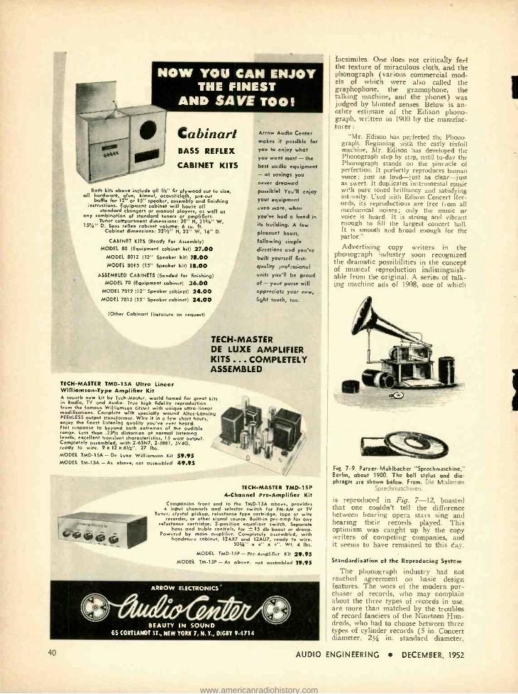
NOW YOU CAN ENJOY THE FINEST
AND SAVE TOO!
Ca binart BASS REFLEX
CABINET KITS
Both kits above include all 310" fir plywood cut to size, all hardware, glue, kimsul, acousticloth, pre -cut
baffle for 12" or 15" speaker, assembly and finishing instructions. Equipment cabinet will house all
standard changers or manual players, as well as any combination of standard tuners or amplifiers.
Tuner compartment dimensions: 20" H, 213/4" W, 151/4" D. Bass reflex cabinet volume; 6 cu. ft.
Cabinet dimensions: 331/2" H, 23" W, 16" D.
CABINET KITS (Ready For Assembly) MODEL 80 (Equipment cabinet kit) 27.00
MODEL 8012 (12" Speaker kit) 18.00 MODEL 8015 (15" Speaker kit) 18.00
ASSEMBLED CABINETS (Sanded for finishing; MODEL 70 (Equipment cabinet) 36.00
MODEL 7012 (12" Speaker cabinet) 24.00 MODEL 7015 (15" Speaker cabinet) 24.00
(Other Cabinart literature on request'
TECH- MASTER TMD -1SA Ultra Linear Williamson -Type Amplifier Kit A superb new kit by Tech Master, world famed for great kits in Radio, TV and Audio. True high fidelity reproduction from the famous Williamson circuit with unique ultra- linear modifications. Complete with specially wound AltecLansing PEERLESS output transformer. Wire it in a few short hours, envoy the finest listening quality you'r ever heard. Flat response to beyond both extremes of the audible range. Less than .25o /a distortion at normal listening levels, excellent transient characteristics, 15 watt output. Completely assembled, with 2 -6SN7, 2 -5881, 5V4G, ready to wire. 9 x 12 x 6'/2 ". 27 lbs. MODEL TMD-15A - De Lux Williamson Kit 59.95 MODEL TM -15A - As above, not assembled 49.95
Arrow Audio Center makes it possible for you to enjoy what you want most - the best audio equipment - at savings you
never dreamed
possible! You'll enjoy your equipment even more, when
you've had a hand in its building. A few pleasant hours, following simple
directions and you've built yourself first- quality professional
units you'll be proud of - your purse will appreciate your new, light touch, too.
TECH -MASTER DE LUXE AMPLIFIER KITS ... COMPLETELY ASSEMBLED
TECH- MASTER TMD -15P 4- Channel Pre -Amplifier Kit
Companion front end to the TMD -15A above, provides 4 input channels and selector switch for FM AM or TV
Tuner, crystal pickup, reluctance type cartridge, tape or wire recorder, or other signal source. Builtin pre -omp for any
reluctance cartridge; 3- position equalizer switch. Separate bass and treble controls, for at 15 db boost or droop.
Powered by main amplifier. Completely assembled, with handsome cabinet, 12AX7 and 12AÚ7, ready to wire.
103" x 4" x 4 ". Wt. 4 lbs.
MODEL TMD -15P - Pre -Amplifier Kit 29.95 MODEL TM-15P - As above, not assembled 19.95
ARROW ELECTRONICS'
BEAUTY IN SOUND 65 (ORTLANDT ST., NEW YORK 7, N. Y., DIGBY 9.4714
40
facsimiles. One does not critically feel the texture of miraculous cloth, and the phonograph (various commercial mod- els of which were also called the graphophone, the gramophone, the talking machine, and the phonet) was judged by blunted senses. Below is an- other estimate of the Edison phono- graph, written in 1900 by the manufac- turer:
"Mr. Edison has perfected the Phono. graph. Beginning with the early tinfoil machine, Mr. Edison has developed the Phonograph step by st:p, until to-day the Phonograph stands on the pinnacle of perfection. It perfectly reproduces human voice; just as loud -just as clear -just as sweet. It duplicates instrumental music with pure toned brilliancy and satisfying iutansity. Used with Edison Concert Rec- ords, its reproductions are free from all mechanical noises; only the music or voice is heard. It is strong and vibrant enough to fill the largest concert hall. It is smooth and broad enough for the parlor."
Advertising copy writers in the phonograph industry soon recognized the dramatic possibilities in the concept of musical reproduction indistinguish- able from the original. A series of talk- ing machine ads of 1908, one of which
Fig. 7 -9. Parzer- Muhlbacher " Sprechmaschine." Berlin, about 1900. The ball stylus and dia- phragm are shown below. From. Die Modernen
Sprechmaschinen.
is reproduced in Fig. 7 -12, boasted that one couldn't tell the difference between hearing opera stars sing and hearing their records played. This optimism was caught up by the copy writers of competing companies, and it seems to have remained to this day.
Standardization of the Reproducing System
The phonograph industry had not reached agreement on basic design features. The woes of the modern pur- chaser of records, who may complain about the three types of records in use, are more than matched by the troubles of record fanciers of the Nineteen Hun- dreds, who had to choose between three types of cylinder records (5 in. Concert diameter, 2% in. standard diameter,
AUDIO ENGINEERING DECEMBER, 1952
www.americanradiohistory.com

and standard diameter with fine -line grooves) and two types of disc records (lateral cut and vertical cut), each of which required its own special player or adapting attachment. It was many years before standardization of basic features was adopted.
The main issues to be settled were: whether to use cylinder or disc records, vertical or lateral recording, and stand- ard or fine -line grooves.
Use of the disc record simplified the problem of casting many copies from a master. Cylinder records had at first to be laboriously re- recorded from the master one at a time, by a special pick- up- recorder unit with a playback stylus
Fig. 7 -10. Columbia cylinder Graphaphone with mechanical friction amplifier. From: The Re-
production of Sound, H. Seymour, 1918.
on one side and a cutting stylus on the other. On the other hand cylinder rec- ords do have a certain advantage over the disc, in that the longitudinal velocity of the stylus relative to the groove re- mains the same throughout the record, while the groove- stylus velocity in a disc record is constantly reduced with the smaller radius of each successive groove. The difficulties of mass produc- tion of cylinder records were finally overcome by a process which made pressings from a master cylinder pos- sible-a record material was chosen which shrank after hardening so that it could be slipped out of the mold. But the simplicity of the disc system won out, and the disc came to be used uni- versally except in dictating machines.
It was more or less natural for cyl- inder records to employ the vertical cutting system and disc records the lateral, although this pairing did not always occur. Edison referred to lateral recording in his 1877 patent, but credit for developing the system in practice goes to Berliner. Figure 7 -13 illustrates the different way in which the groove is shaped for the two types of recording.
only AZTEC manufactures
a complete line of
high fidelity equipment!
Attempts to adapt unmated parts together into a home
music system are often unsuccessful. Buy Altec and you
not only get the highest quality but you get components
designed to worn logether. Each unit plugs into the
others. Easy to install. Designed for eye as well as ear
appeal. In hume installations as in all other audio
fie ds, the Altec name is your assurance of the best.
:"...-' »»..... ., .
AM -FM TUNER
303B - The best tuner money can buy for audio quality ... wide band super het AM ...superlative FM ...equalized phono pre - amp ...extra input for tape ...record cross- over frequency selection ...equalization for LP records ... bass and treble rise and droop .. built in power supply ... more depend-
able features than any other tuner.
REMOTE AMPLIFIER
A -433A - Beautiful compact control unit for use with phono when 303A tuner is not re- quired. Contains VR phono preamp and all of the novel features found in the 303A tuner ..three inputs... perfect for reproduction
from records, tape and radio tuners.
POWER AMPLIFIER
A -333A - The power amplifier without a peer ... 15 watts with less than 1/2% har- monic distortion ... 27 watts with less than 5% distortion ... flat from 20-20,000 cycles ...completely controlled from 303A tuner or A -433A remote amplifier.
LOUDSPEAKER
DUPLEX -The exclusive Altec "duplex" loud- speakers are the only speakers guaranteed from 30 to 22,000 cycles. Available in three sizes and power capacities.
820A- Altec's new corner speaker system... the concert grand of the loudspeaker world ...two 15" woofers... high frequency speaker and multicellular horn in a furniture cabinet provide famous Altec "Voice of the Theatre" quality for the home.
SEE YOUR DEALER OR WRITE TODAY
MONICA BLVD., BEVERLY HILLS, CALIF.
ETN AVENUE, NEW YORK 13, NEW YORK
AUDIO ENGINEERING - DECEMBER, 1952 41
www.americanradiohistory.com

WIDE RANGE -HIGH FIDELITY
42
You'll want to see and hear this outstanding equipment. Yes, get to know the Stromberg- Carlson line. Write for more information about the numbers listed below or order direct from Lafayette, famous for High Fidelity for 30 years.
STROMBERG-CARLSON AM-FM Tuner 88-401 has a sensitivity of 5 micro -volts on both bands. AM circuit has wide and narrow selectivity. Fre- quency response 20 to 20,000 cps ±115 db. Har- monic distortion less than 1 %. 12 tubes plus rec- tifier and tuning eye. AFC switch on front panel. Completely ready to install with all hardware. Silver gray finish. Size 111/2" x 62" x 11 ". Shp. Wt. 12 lbs. 130.93
STROMBERG- CARLSON Hi -FI 10 Watt Ampli- fier AR -410. The AR -410 Hi -Fi Amplifier provides 10 watts from a single chassis. Frequency re- sponse 20 to 20,000 cps with less than 1% distor- tion. Response flat, ±1 db. Six input connections are provided for front panel selection. Treble con- trol provides 5 db boost and 15 db droop at 10,000 cps: bass control provides 15 db boost or droop at 50 cps. Loudness control follows Fletcher - Munson curves. (fray panel matches tuner. Size 11" W x 7" H x 8" Deep. Shp. Wt. 25 lbs. 79.95
STROMBERG- CARLSON De Luxe Amplifier AR- 425. 25 watts. Designed as a dual chassis; con- trols are located on the pre -amplifier. Response 20 to 20,000 cps, lese than 1% harmonic distor- tion; hum 80 db down. Tone controle provide 15 db boost and 20 db droop. 5- position brilliance control, 3- section loudness control. Input selec- tor controls 7 positions; microphone, FFRR, LP, AES, radio, TV, tape or crystal phono. With 6, Interconnecting cable. Sizes: Power amplifier 16" x 81/2" x 7" ; Pre -amp 121" x 5" x 51/2 ". Finish brown mahogany. 189.93
STROMBF.RO- CARLSON SPEAKERS. RF-473 15" coax speaker provides exceptional wide range response of 30 to 16,500 cps, with a distribution angle of 90" vertical and horizontal. Capacity 40 watts of program material. Low frequencies are fed to 15" seamless cone with a 3" ve. The 5" tweeter in a parametic horn with acoustic lens. Input Impedance 16 ohms, S lb. Alnico V magnet. Wt. 50 lbs. 179.03
RF-471 12" coax speaker provides exceptional performance. The 31" seamless tweeter is suspended in Charpinchoe leather to eliminate violent peaks and dips in high frequencies up to 15,000 cps. The tone range down to 30 cps through a 12" seamless low frequency cone with a voice coil of 11/2" diameter. Power capacity 32 watts of program material. 8 ohm impedance. Wt. 15 lbs. 49.93
STROMBERG- CARLSON labyrinth RL -485. With the RL -485 Exponential Acoustical Laby- rinth Kit, any speaker cabinet, of sufficient size, can he converted to the famous Stromberg -Cari- son Labyrinth. Will fit any cabinet with the fol- lowing minimum inside dimensions: 39" H 24" W 20" D. Kit contains all necessary material and installation hardware and instructions. 20.00
STROMBERG- CARLSON Model TV -421 TV Chassis. The TV Tuner Chassis TV -421 features a bright, well -contrasted picture and exceptional performance in fringe areas. Equipped with a 21" picture tube and designed to receive channels 2 through 13 (adaptable to U.H.F. channels). The chassis is supplied with 19 tubes plus 3 recti- fiers, plus mask and all mounting hardware. Size 20- 11 /16" W 231/2" D 211/2" H (Including picture tube). Shp. Wt. approx. 75 lbs. 299.95 Send for free High Fidelity catalog and further information on the Stromberg -Carlson line. Write.
NEW YORK
BRONX NEWARK BOSTON
100 SIXTH AVE.
542 E. Fordham Rd.
The Edison company continued to use vertical cutting in their heavy disc rec- ords for many years, but lateral cut records, the type made by the old phon- autograph, finally became the standard for all home discs.
Grooves in the first records were slightly wider than the modern stand- ard groove, cut 100 to the inch. Playing time for a cylinder was about two min- utes. This time was increased by the introduction of "microgroove" tech- nique, which used a groove of approxi- mately the same width as the modern LP groove and increased the number of grooves per inch to 200, not much less than the pitch of contemporary microgroove records. "Long- playing" records of the first decade of the twen- tieth century were accompanied by the same advertising acclaim as those of the sixth. Ads for Edison fine -line cylinder records give one the feeling of a visitor to an ancient site who finds things strangely familiar. But the microgroove record lost out until many years later.
There was not too much room for im- provement in the acoustic phonograph. The reproducer head was made as sen- sitive as possible, and the "morning glory" horn, so named because of its
Fig. 7 -11. French Phonograph (Pathé, about 1905) with compressed air amplifier. From:
Le Génie Civil, 1906.
exponential flare, was substituted for the conical one. Then the outside horn was replaced by a folded horn in the cabinet, rigid with respect to the cabinet but connected by a flexible joint to the hollow tone arm, which itself formed part of the flare. Larger horns housed in console cabinets made the coupling between the diaphragm and the air of the room more efficient, particularly in the bass, producing more volume, fuller tone, and a decrease in distortion.
The Phonograph Amplifier Direct recording and reproduction has
severe limitations. It is difficult if not impossibe, with this technique, to radiate enough energy into the room to create an adequate intensity of sound. Even if the reproducing styus were so well loaded acoustically that the vibrations produced by the record groove did pro- duce the (lesired intencity level, the
AUDIO ENGINEERING DECEMBER, 1952
www.americanradiohistory.com

r
i
1
Which is
which?
Victor )
Fig. 7 -12. "High Fidelity" in 1908.
groove walls would be so strained that they would probably crumble. In addi- tion the natural resonances of the sys- tem are very prominent. Suppression of the violence of resonant behavior by damping, and by the design which places the resonant frequencies out of the audible range, reduces the effi- ciency further. The use of very light loading on the stylus has a similar ef- fect. Such measures as these are made feasible. however, by amplification. The reduced power shaped by the record groove instead of being used for direct acoustical radiation, is employed to con- trol an independent source of greater energy.
Edison had developed a pneumatic amplifying or "relay" system which he called the aerophone, but it was designed as a public address system for speech rather than for records. A successful phonograph amplifier was employed in the British auxetophone, the idea for which was first patented by Short in 1898 and developed further by Parsons soon after. This device contained a pneumatic system like that of the aero- phone ; the vibrations induced in the reproducing system were used to throttle periodically a steady flow of filtered air furnished by a motor -driven compres- sor. The reproducer head contained a stylus- actuated pneumatic valve which released bursts of air in the proper form and sequence to imitate the recorded sound. Short directed the air bursts against a reproducing diaphragm, but Parsons found that the modulated air stream could be released directly into the room. A contemporary critic of the auxetophone wrote that it was suited only to public halls, because of a con- stant hissing produced by the air flow and because the volume was too great. ( !)
Another type of amplifier used com- mercially was purely mechanical in nature. The stylus was coupled to the
Brighter, Sharper
TV Reception
WITH THE TURNER MODEL TV -2 BOOSTER You get clearer, sharper pictures with a minimum of annoying interference and snow even in weak signal areas with the TURNER TV -2 Booster. It's designed with an eye to beauty as well as out- standing performance. The rich, mahogany plas- tic cabinet is a handsome addition to any room ... the high quality cascode circuit reduces noise and snow. producing an excellent picture even in extreme fringe areas. The TURNER Booster is simple in operation. A single tuning knob permits fine adjustment for best reception of picture and audio over all 12 TV channels. The unit is quickly and easily installed on any television set. Get the best possible TV re- ception ... get the TURNER Model TV -2 Booster!
The TURNER Company 929 17th St. N.E. Cedar Rapids, Iowa
IN CANADA: Canadian Marconi Company, Toronto, Ont., and Branches.
EXPORT: Ad. Auriema, Inc., 89 Broad Street, New York 4, N. Y.
AUDIO ENGINEERING DECEMBER, 1952 43
www.americanradiohistory.com

SUBSCRIBE TO
for LIFE THE LASTING CHRISTMAS PRESENT
NaLuL you can eliminate the bother of renewing every year or so. If you live in con- tinental United States, you can subscribe for life at the new rate of only $25.00 and receive Æ from now on. If you are a subscriber now, we will refund a pro -rated amount based on your re- maining term, or you can transfer it to a friend. Pocket "membership" card given as your receipt. This offer is good only in the U. S. and applies only to sub- scriptions entered by sending your check or money order di- rect to
RADIO MAGAZINES, INC. P. O. Box 629 Mineola, N. Y.
LET YOUR OWN EAR TELL YOU
This Revolutionary, New General Hi Fi
&ruch-cJctnj HIGH FIDELITY SPEAKER
I AMAZING PERFORMANCE COMBINES: SENSATIONAL LOW COST
UNUSUAL SMALL SIZE
Bring to Your Home a New High In Authentic Sound Reproduction. Hear Fine Music as it is Originally Played or Recorded
CONCERT HALL CLARITY . . . Now enjoy true, mellow tone and life -like performance at NEW LOW COST! In- expensive enough to use as an auxiliary extension in other rooms, many speakers can be attached to one amplifier, without distortion or power loss.
EASY TO INSTALL . . . New triangular shape and light weight allows easy ceiling corner mounting, usually impos- sible with larger, bulkier speakers. Four identical speakers housed in a handsome, mahogany veneer cabinet -in your choice of four modern decorator finishes to blend with every decor.
DELUXE MODEL
The Baruch - Lang speaker is also avail- able in this deluxe model, with a hand- some frame and grill cloth for added beau- ty. Available in the same luxury finishes
Blonde Modern, Rich Mahogany, Chi- nese Black, and Nat- ural Unfinished, only $29.95
44
i
1
A SCIENTIFIC MARVEL OF ELECTRONIC ENGINEERING Developed at one of the leading elec- tro - accoustical laboratories in the East. The Baruch - Lang received ex- t ravagent praise at recent audioshowsand in leading na- tional maga- zines. It ac- complishes the
unbelievable feat of repro- ducing bass tones down to 40 cps in 21/2 cubic ft. Only 13" High; weighing 10 lbs. Speaker provides AMAZ- ING HIGH FIDELITY AND EFFICIENCY 40- 12,000 cps dropping to 15,000. The unique cabinet contains 4 identical 5" PM speakers and 15 holes which radiate bass. The cabinet is otherwise empty except for a diagonal baffle also containing 15 holes, backed by an accoustic resistance.
CHECK THESE LUXURY FEATURES Excellent tone and additional power when needed Smaller and lighter for limited areas Triangular, for easy corner mounting Quick and simple to attach
Four fine decorator finishes Complete in fine wood housing that requires no additional cabinets
AVAILABLE AT LEADING DEALERS or write to GENERAL HI FI Co., Studio H -4 -12, 799 Broadway, New York 3, N. Y. for the nome of your nearest dealer and FREE INFORMATION.
AUDIO
reproducing diaphragm via a string and friction shoe which passed over a rotat= ing wheel, and extra energy was -picked up through friction with the surface of the wheel. The principle was the same as that of the ship's capstan. When mo- tion of the stylus caused it to tighten up on the string, frictional coupling to the wheel was increased, and diaphragm dis- placement was augmented by wheel mo- tion. When the stylus loosened tension on the string the diaphragm returned to its normal position due to elasticity.
The most revolutionary advance in phonograph technique after the intro- duction of the Bell -Tainter system was the marriage of recording and elec-
TOP SURFACE OF RECORD
//.Y////////// ,/// //.G!%///iil % CROSS.SECTION OF RECORD RUNNING PARALLEL
TO GROOVE
BOTTOM OF GROOVE
TOP VIEW OF RECORD GROOVE
Fig. 7 -13. (A) Vertical or hill -and -dale record ing, originally known as the "phonograph cut." (Bl Lateral recording, originally called the
"gramophone cut"
tronics. Electrical recording and re- production had been experimented with since the earliest days of the phono- graph, and was mentioned in Edison's original patent application, but the development of amplifying tubes and superior electro- mechanical equipment was necessary for realization of its ad- vantages. In electrical recording, sound was no longer impressed directly onto the record cutting head, but was first converted to an electrical signal through a microphone and amplifier. This sig- nal, whose electrical wave form cor- responded to the acoustic wave form of the sound, was fed to an electric cutting head. The cutting stylus was displaced by the electrical power applied to it rather than by acoustic power.
An electrical cutter is basically a motor. Playback had to involve a reverse electro- mechanical process, using a pickup head which acted as an electrical generator. Playback stylus displacement induced voltages in the pickup of the same wave form as that of the groove. and these voltages were amplified and converted into sound by a loudspeaker.
Electronic amplifiers can now be built whose degree of fidelity to the in- put signal compares favorably with the degree of accuracy with which the hu- man ear can judge distortion. This is not true of electro- mechanical and electro- acoustic apparatus; the greatest obstruction in the path towards fidelity is still the pivoted or suspended mechan- ical device. We have not yet learned how to control the machine with the same precision with which we can con- trol the electronic circuit. The prob- lems of the contemporary audio engi-
ENGINEERING DECEMBER, 1952
www.americanradiohistory.com

neer are thus not as far removed from those of phonograph designers of the Nineteen Hundreds as one might think.
PATENTS [from page 2]
V., the key to the system, is a high -mu triode biased by R,r-R,, across the B- supply, with the cathode bypassed by C:. The grid is also bypassed for audio by C.. C, is the conventional screen bypass for V,. The triode normally has a high plate resistance and draws little current through R. and K. It also has little shunting effect on the signal for this reason ; the same is true for resistor string R.-R> RrR,. V, causes no degeneration of signal because its grid and cathode are bypassed.
The voltage on the plate of V, is essen- tially that on the plate of V,. When the V, plate voltage rises more than, say, 20 volts above its resting value (the result of a sudden negative control -bias rise on its grid) the heightened voltage on the plate of V, brings it into the low- resistance, high - plate- current region. The current of V, is drawn through R,, opposing the rise in voltage across R, (which is, of course, the output voltage of V,) and keeping the undue rise down to negligible proportions. The effect is to clip the sudden transient and prevent unpleasant noises. As an illustration, an unchecked transient may cause a 100 -volt peak ; the clipper keeps it down to about 20 volts, well within the normal level. Negative V, plate swings tend to be slower and do not cause audible transients, so no negative clipp'ng is required.
Screen compensation works this way :
When a negative control voltage rises on the grid of V,, screen current through the screen dropping resistors R. and R, de- creases and screen voltage becomes more positive. This rise appears on the grid of Vs.
The plate current of V. increases; since it is drawn through R., it causes a greater drop across R. which tends to counteract the change in screen voltage.
Values of components and tube types are not given in the patent specification but, as usual, a little thought would indicate them.
A copy of any patent specification may be obtained for 254 from The Commissioner of Patents, Washington 25, D. C.
MAGNECORD and VOX Join
With New Tape Library
"Magnecordings by Vox," first full -range recorded tapes for commercial sales fea- turing major orchestras with noted con- ductors and soloists, are rapidly being made available throughout the country.
These "Magnecordings" are offered as both full and half -track recordings on standard recording tape at 71/4 in. /sec., thus providing either hour or half -hour pro- grams on a single 7 -in. reel, depending on the type of recording desired. Special equal- ization in recording will give reproduction to 15,000 cps. Price for 7 -in. half -track reel -one hour -is pegged at $9.95.
Recordings will be made by Magnecord for MaVoTape, Inc. from the "master" tapes of Vox Productions, Inc., and will be distributed initially through Magnecord outlets. Plans call for six releases per month.
TWO STANCOR TRANSFORMERS
are part of Stancor's extensive line of catalog part numbers,
available for immediate delivery from your local electronic parts distributor
I 1
11
CATHODE RAY TUBE POWER TRANSFORMER, P -8151, for use with type 2X2 recti- fier tubes in a conventional half -wave high voltage supply. Plate supply 2,400 AC volts, half wave, 5.0 DCMA. Rectifier filament 2.5 volts at 2.0 amps. Other windings, 2.5 volts at 2.0 amps. Height 4s/te, base area 3%, z
HIGH-FIDELITY INPUT TRANSFORMER, WF -20, for low impedance micro- phone, pickup or line to grid. Primary impedance 50, 125/I50, 200. 250. 333, 500'600 ohms. Secondary impedance 50.000 ohms. Frequency response 90- 20,000 cps. ± 2 db. Negligible har- monic and intermodulation distortion. Grey enamel cast case with phenolic terminal board and tapped holes for flush mounting. 2" high by 1 %" square.
These units are examples of the many specialized transformers in the Stancor cataloged line ... units that are regularly carried in stock.
Check the Stancor Catalog first when you need transformers for industrial, amateur, audio, radio, TV or any other electronic application. You're almost sure to find it there.
You can get your FREE copy from your Stancor distributor, or by writing Stancor direct.
STANDARD TRANSFORMER CORPORATION is one of the lead-
ing suppliers of industrial and military transformers
built to the manufacturers specifications.
Stancor is your best source for hard -to- design, tough -
to -build transformers. At Stancor you will have the serv-
ices of experienced design engineers and a fully equipped
test laboratory with complete facilities for in -plant
testing of MIL -T -27 components. Your transformers will
be built in the industry's newest transformer plant, using
the most modern production and test equipment.
AUDIO ENGINEERING DECEMBER,
v 1952
STANDARD TRANSFORMER CORPORATION 3568 Elston Avenue. Chicago 18, Illinois
45
www.americanradiohistory.com

1
J
NEW PRODUCTS Portable Tape Recorder. i' rfornancc
based on NARTB specifications is af- forded by the new Magnemite Model 610 -SD battery -powered tape recorder with spring -wound motor recently intro- duced by Amplifier Corp. of America, 398 -4 Broadway, New York 13, N. Y. Constant tape speed, with flutter content within t 0.1 per cent over the full wind- ing cycle of six minutes, is achieved by means of a patented centrifugal flyball governor on the spring motor. The mo- tor may be rewound during operation without any perceptible effect on record- ing or playback. A triple -purpose indi- cator lamp signals 30 seconds before re- winding is necessary, shows if the power switch is accidentally left on, and indi-
cates any undue variation in tape speed. The 610 -SD operates at a tape speed of 7% ins. /sec., furnishing 15 minutes of continuous playing time on a standard 5 -in. tape reel. Recordings may be played back on any standard studio equipment. Measuring only 11% x 10 x 754 ins., the Magnemite weighs only 15 lbs. complete with self -contained batteries which af- ford 100 operating hours without replace- ment. Technical specifications and prices will be supplied on request.
Sound Analyser. A new instrument which, in addition to measuring inten- sity, separates sound signals into their component frequency bands, has recently been added to the extensive line of noise - measuring devices manufactured by Her- mon Hosmer Scott, Inc., 385 Putnam
Ave., Cambridge 39, Mass. Designated Type 420 -A Sound Analyzer the unit contains high- and low -pass filters which can be independently adjusted in steps of one -half octave. A simple interlock permits the pass -band width to be fixed In any multiple of one -half octave. The position of the pass -band can then be adjusted throughout the audible range by means of a single control. The 420 -A ex- ceeds all proposed specifications of the ASA for filter -type sound analyzers. The instrument is housed in a saddle- leather carrying case and may be used while the operator is walking about. Weight is 20 lbs. and dimensions are 10 x 10 x 6 in. Bulletin will be mailed on request.
Multi- impedance Dynamic Microphone. There is little to be required of a micro- phone, both in performance and flexibil- ity that is not present in the new Asiatic unidirectional Model DR -11. Frequency
response is 40 to 10,000 cps and available impedances, achieved by means of a built -in transformer and selector switch, are 50, 200, 500 ohms and high. Output level is - 64 db. The unit employs Astatic's sintered -metal method of acoustic phase shifting. Front -to -back pickup differential is approximately 15 db. Dynamic element is floated in rubber for structural stability and reduction of mechanical pickup. The DR -11 is finished in satin chrome with maroon trim, and is supplied with Amphenol connector and 18 -ft. shielded cable. Astatic Corporation, Conneaut, Ohio.
Magnetic Tape aecorder. Five piano - type pushbuttons permit selection of all operating functions, including fast forward, playback, stop, record, and fast reverse, in a new low -priced Knight tape recorder recently announced by Allied Radio Corporation, 833 W. Jackson Blvd., Chicago 7, III. Panel- mounted control af- fords choice of 734 or 3% ins. /sec. re- cording speed. Frequency response at the higher speed is 70 to 8500 cps. Playback is by means of a built -in power -amplifier and speaker, with additional provision for feeding external equipment. Ex- tremely compact, the new Knight re-
corder measures only 14 x 12 x 7 ins. It is housed in a sturdy, luggage -type car - rying case. Carrying weight is less than 22 lbs. Supplied complete with crystal microphone, 600 -ft. roll of tape, and 5 -in. take -up spool.
Magnetic Tape Recorder. Many im- provements over earlier models are in- cluded in the new Eicor Model 230 tape recorder. Major design emphasis has been placed on functional styling, an example of which is the new "Finger -Flip" Control arrangement which affords simultaneous switching of mechanical and amplifying systems. Built -in dual-speed capstan per - mita instant choice of 71¢- or 3% -in. re- cording speed. Normally furnished for dual -track operation, the 230 features a plug -in recording head which can easily be replaced with a single -track head for applications which require editing and splicing. An automatically engaged pres- sure roller keeps tape in close contact with capstan for elimination of slippage
and consequent reduction of wow and flutter. Frequency response at 7% ins./ sec. recording speed is 70 to 8000 cps within t 3 db. Cover for portable case carries microphone, break -away power cord, and extra reels. Eicor, Inc., 1501 W. Congress St., Chicago 7, I11.
Sigh-Quality Amplifier. Although ex- tremely compact, the new Deco Type PTL -8 amplifier affords a calibre of per- formance normally expected of ,units considerably larger. Combining an equal- izing preamplifier and a power amplifier on a single chassis, the unit has a rated power output of 9 watts with less than 1 per cent harmonic distortion. Intermod- ulation is said to be correspondingly low. Frequency response is 20 to 20,000 cps within ± 1 db. Hum level is 90 db below rated output. Panel controls include sep- arate bass and treble controls, loudness control, and a combined input selector and phono- equalization switch which ac-
commodates all types of records when played with a variable- reluctance pickup. Dynamics Engineering Co., 234 W. Elm St., Oxnard, Calif.
Magnetic Tape Por Instrumentation. In view of the rapidly increasing usage of tape recording equipment for instrumen- tation and data analysis, Minnesota Min- ing and Manufacturing Co., St. Paul, Minn., is now producing Scotch tape pre- selected for telemetering and other in- strumentation uses. The new tape is relatively free of nodules, or surface im- perfections, and represents considerable improvement over standard tape for in- strumentation applications, although it offers no superiority over regular Scotch tape for the recording of musical pro- grams.
46 AUDIO ENGINEERING DECEMBER, 1952
www.americanradiohistory.com

1
F
ORGAN INSTALLATION [from page 16]
driver unit and associated horn. Simi- larly, above 4000 cps the dividing net- work again diverts the input to a unique horn -type unit designed especially for this very high frequency range.
It is apparent that such a system does not require the use of large and heavy multicellular horns and low crossover frequency thus substantially simplifying the system. As the frequency increases, progressively smaller sources are em- ployed which can therefore have high efficiency in their limited band width (approximately three octaves) as well as improved polar characteristics. The resulting reproducer was found to have very low distortion at the maximum power levels encountered from the low- est notes of 64 cps to well beyond the 12,000 -cps value specified. This low - frequency limit with wavelength of about 18 feet obviously simplified the problem, and the horn mouth size of 33 by 36 in. was entirely adequate. Over- all dimensions of the reproducer are approximately 38 wide x 62 high x 24 in. deep.
Pedal -Channel Reproducers
The two pedal- channel reproducers each consisted of a large exponential horn driven by two 15 -inch Jensen P15 -LL special low- frequency direct - radiator type driver units. These horns had continuous exponentially flaring walls with design cutoff of approxi- mately 30 cps. Mouth size was 57 x 89 in. yielding an area of about 352 square feet. The throat area was approximately 354 sq. in.. giving excellent loading characteristics for the two 15 -inch loud- speakers. Tests verified that no enclosing chamber was necessary over the back of the driver units. Figure 5 is a diagram of the pedal channel reproducers.
The wavelength at 32 cycles is about 36 feet, and there was no floor or simi- lar reflecting surface adjacent to the horn mouth to increase its apparent size. However, with this excellent horn load- ing the electrical power handling ca- pacity of the 15 -inch drivers was easily in excess of the 30 watts specified. Re- production of all pedal tones down to 32 cps met the requirements of high output and low distortion at the highest power level, encountered.
The Loudspeaker Array
Because of the necessity for suspend- ing the entire loudspeaker array, it was imperative to obtain the maximum in efficiency and power handling capacity so that the number of reproducers could be kept at a minimum. The further re- quirements for low distortion and wide frequency range clearly indicated the necessity for high -quality loudspeakers.
The entire array of reproducers was supported on a platform and hoisted by power winch to a centrally located po-
By Popular Demand! Another Big Page in
Leonard History!
PRESTO PT -920
TAPE RECORDER
SYSTEM
Developed for fully professional work, the PT -920 is the ideal recorder for
schools and university work. The unit consists of a 3 motor driven system;
separate erase, record and reproduce heads; and 2 separate amplifiers
. one for recording and the other for monitoring. Continuous recording
may be had through the use of 2 RC 7 mechanisms and 1 amplifier with the use of the Presto SA 10 changeover switch. Complete specifications
on request.
FAIRCHILD 3 WAY
TURRET HEAD ARM
RC -7 .. $425.00 net
A -920 324.00 net
Ideal for all types of records, this 3 -way arm assures freedom from
troublesome arm resonance and distortion. Stylus pressure is adjustable
... spring tension set at factory for 15 grams standard; 6 grams micro- groove. Overall length: 18' /z "; center pin of turntable to center of arm
base: 13% "; base diameter: 27/e ". ;65 net
FAIRCHILD 215B CARTRIDGE
Famous Fairchild HIGH COMPLIANCE reduces
needle wear, stylus wear, needle talk, record hiss and arm resonance!
You'll get improved low frequency and NO tracking distortion! Moving coil design ... finest diamond stylus.
215B 2.5 mil stylus tip $42.50 nct 21 5C 3.0 mil stylus tip 42.50 nct 215A 1.0 mil LP stylus 47.50 net
PRESTO 15G
3 SPEED MICROGROOVE
& STANDARD TURNTABLE
Here's a top quality unit for all 33 -1/3. 45 and 78 rpm reproduction. Easily
connected to any radio or audio amplifier, the 15G boasts a heavy cast
aluminum 12" turntable ... precision idler wheels and motor pulley . .
and minimum "wow ". $49.50 net
69 CORTLANDT ST., NEW YORK 7, N. Y.
equdid Ma4t Dept. Al2 CORTLANDT 7- 0315 -9
The House Built on Service
r-_
J AUDIO ENGINEERING DECEMBER, 1952 47
www.americanradiohistory.com

sition near the roof. Figure 6 shows the complete array before hoisting. The in- dividual reproducers were arranged on the periphery of the platform leaving sufficient working space in the center for all required operations. The platform was accessible from a catwalk just un- der the roof. All cable connections were completed after the array was raised into position. Each manual- channel repro- ducer horn was hinged to the platform at its back edge and could be tipped back to lie flat for access to the Triaxial loud- speaker driver unit. These reproducers were locked in normal position by latch- ing to the next adjacent reproducers. The driver units for the pedal channel reproducers were directly accessible from the back.
As indicated in the Huck diagram
separate cables were used for each man- ual reproducer and for each driver unit in the pedal reproducers. These cables extended from the amplifiers, located adjacent to the console near one end of the auditorium, to the loudspeaker array. These 14 -ga. cables with a length of approximately 300 feet were satisfac- tory for use with the 16-ohm load im- pedances, thus eliminating the need of additional transformers. Plug connec- tors at the loudspeaker array simplified installation.
All of the individual reproducers were oriented so that the "axes of radiation" all would lie in a horizontal plane di- recting the sound into the slanting (domed) roof. The sound was thus re- flected downward into the audience add- ing :I feeling of "expansiveness ". This
ap.Ìre//e/ed
RES !7
-ï J
\TANNOY DUAL CONCENTRIC
LOUDSPEAKER SYSTEMS
Now experience the amazing listenability of wide range response in perfect balance. Hear the world famous Tannoy Dual Concentric Loudspeaker System,
lproviding optimum fidelity at any
evel from the audibility thresh- old up to full room volume. Features of the Tannoy System include:
Substantially flat response from 40. 20,000 cycles per second. Con- centric sources for both NF and
LF components avoiding inter- ference at crossover. HF horn formed by machined center pole and LF diaphragm, these com- bined with a special throat insure correct HF match. lntermodulation product less than two percent.
Hear It to appreciate it! Write for free brochure and name of nearest distributor today. 12" and 15" types, handling 15, 25 watts.
SOME DISTRIBUTORSHIPS STILL AVAILABLE
TANNOY BEAM INSTRUMENTS CORPORATION 350 FIFTH AVENUE NEW YORK I NEW YORK
48
procedure, while quite satisfactory for the reproduction of organ type music, is entirely contrary to the required pro- cedure for public address systems where the sound must be directed to the audi- ence and all reflection must be elimi- nated so far as possible. The deep bal- conies- usually the downfall of the PA system -proved no particular problem due to the high percentage of reflected sound energy in the auditorium. The re- production was entirely satisfactory in all parts of the hall even for the high - frequency range.
With such an application as this there is no opportunity to test performance before the actual final operation because the system performance is dependent on the audience size and the ambient noise. Many doubts existed as to the adequacy of the system despite the favorable per- formance with an empty auditorium. However, the performance during the two conventions justified the careful planning of the system, and unsolicited praise from many of the official person- nel verified the acceptability and ade- quacy of the system.
TABLE 1
SPECIFICATIONS FOR MODEL 2C2 CON NSONATA
Swell Manual: 61 Keys Great Manual: 61 keys Pedalboard standard AGO,: 32 notes
Stop list: Great
Open Diapason Melodia Gross Flute Dulciana Gamba Trumpet Great Union Off 18') Great 4' Swell to Great 16' Swell to Great 8' Swell to Great 4' Swell to Great 2' Great Tremolo Off
Echo Echo and Main
General Tremolo -Light Tremolo- Medium Tremolo -Heavy
Pedal Major Bass Gedeckt Bourdon Dulciana Great to Pedal 8' Swell to Pedal 8'
Swell Geigen Diapason Harmonic Flute Gedeckt Echo Salicional Viola da Gamba Vox Humana Oboe Swel 16' Swel Unison Off 18'1 Swel 4' Swel 2 2/3' Swel 2' Swel 1 3/5' Swel Tremolo Off
Balanced expression pedal controlling over -all volume of entire instrument
Off /On power switch with pilot light
Note: Tremolo is activated on entire organ bs depressing any of the tremolo switches. Is cancelled on individual manuals by using Tremolo Off switches.
AUDIO ENGINEERING DECEMBER, 1952
7
www.americanradiohistory.com

NETWORKS
[from page 17]
ing, the source impedance seen by each speaker should be as low as possible. It is evident that conditions (1) and
(2) will be implicitly satisfied if re- quirements (3) and (4) are met.
Two networks that will fulfill require- ments (1) through (4) are shown in Fig. 1, where R is the impedance of the speaker, and fa (the "crossover" fre- quency) is the frequency at which the radiated power is equally divided be- tween the two speakers. The input im- pedance of either of these two networks is equal to R, and is independent of fre- quen.y, if the following conditions are met: (a) the impedances of the speakers must be equal, and (b) the impedance of each speaker must be a pure resist- ance.
Circuit A of Fig. 1 provides a con - sider:ably sharper frequency division of the signal than does circuit B ; the power radiated by each speaker of circuit A falls off at a rate of 12 db per octave in the cut-off band, whereas the slope for c rcuit B is 6 db per octave. Which of these circuits is the more desirable deperds on several factors. Use of the sharper slope, for instance, reduces the rang( of frequency over which any one speaker has to handle an appreciable amou it of power. However, unless great care is exercised in locating the speakers, this same sharpness of cross- over may destroy the illusion that the soup( is being radiated from a single source, since the fact that the sound is being produced in two frequency bands is more obvious under these conditions.
Relative Advantages
From the point of view of the hobby- ist, circuit B offers certain advantages over the more complicated circuit A. It is true that a saving in complexity of the circuit is probably of negligible im- porta:tce, per se; and certainly any re- duction in size and weight of the cir- cuit will be a small percentage of the volun.e and weight inherent in the speak ers themselves. However, there is a material saving in the cost of the compcnents required -circuit B re- quires only about 36 per cent of the inductance, and some 70 per cent of the capaci:ance required by circuit A for a sys.xm having the same crossover frequency and the same speaker imped- ance. Since the capacitors used in a high -fidelity system must be of the high- quality, oil -filled variety, and since the values of capacitance required in a practical system are quite large, a re- duction by 30 per cent in capacitance represents a very real reduction in cost. Moreover, use of a smaller inductance will result in a lower resistance in the inductors, with a slight resultant gain in efficiency, and with a concomitant improvement in dafnping.
In circuit B, any resistance in the in-
ductor winding can be written off as part of the speaker resistance, and can easily be balanced by addition of a padding resistance in the other half of the circuit. However, a reasonable amount of resistance unbalance can be tolerated, except when feedback is used from the voice -coil windings. In the latter case, phase shift may become ex- cessive if balance is not maintained.
Similarly, inductance in the speaker winding can be regarded as part of the inductor in one branch of circuit B. Unfortunately, however, since this speaker is carrying the low- frequency components of the signal, the induct- ance in this speaker is of less impor- tance than it is in the other speaker, which is not compensated by the cir-
cuit configuration. By application of Thévenin's theorem, one may see that it is possible to regard shunt capaci- tance around the high- frequency speaker as included in the series ca- pacitor, although this capacitance should be negligible, even at the highest audio frequencies.
So far, nothing has been said about requirement (5) above, i.e., that the speakers should see a low- impedance source. Unfortunately, both of the above circuits are weak in this re- spect, circuit B perhaps having a slight advantage over circuit A. Moreover, the source impedance -and hence the speaker damping -will be a function of frequency. If speaker resonance occurs at a frequency at which the damping
MODEL RC -80 Fully automatic with automatic stop!
INCOMPARABLY
BETTER -YET PRICED TO COMPETE
WITH THE ORDINARY!
MRD THE WORLD'S FINEST RECORD CHANGER
EVERY FEATURE TESTED FOR FINEST PERFORMANCE
,
PUSHER TYPE PLATFORM:
It always works
TWO INTERCHANGEABLE
A Plays records as intended
HEAVY r_DRIVE SHAFT:
- c.} -.71,- No wows, ti no wavers
JEWEL MOUNTED
1L TONE ARM:
"` Disturbing resonance
eliminated
HEAVY DUTY SILENT MOTOR:
Absolute] no rumble
, 1 \a
WEIGHTED TURNTABLE:
Gives
action
MUTING SWITCH: . Silence 'í records
SIMPLE INSTALLATION:
-r+w+ Fits former Garrard cut.
For complete information write to Dept. AE -12
GA RARD SALES CORPORATION 164 DUANE STREET, NEW YORK 13, N. Y.
AUDIO ENGINEERING DECEMBER, 1952 49
www.americanradiohistory.com
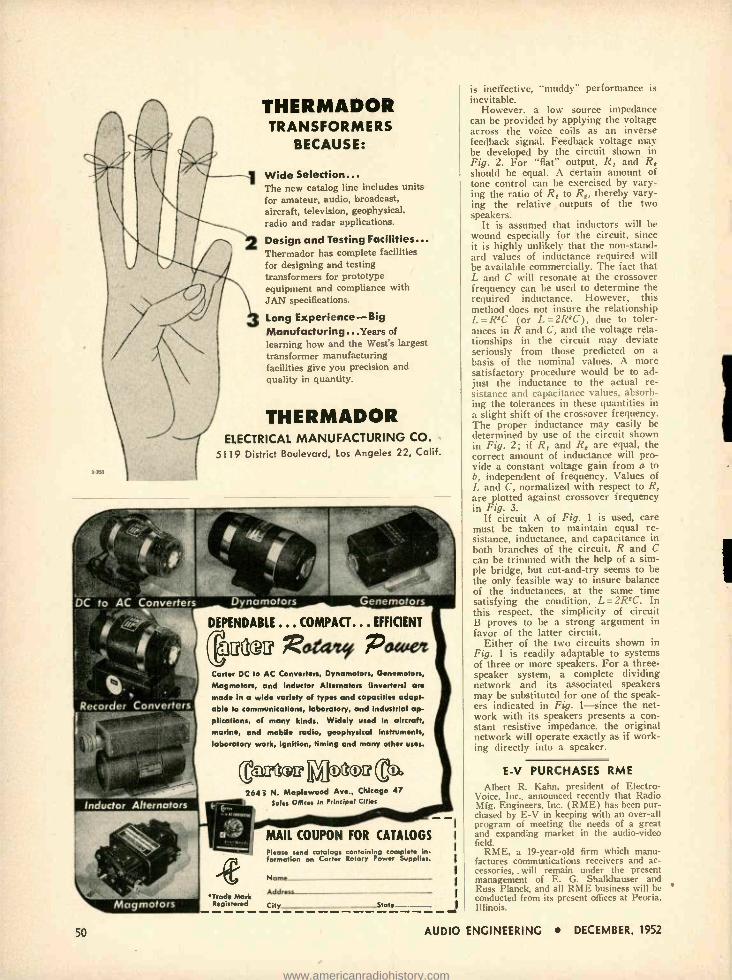
THERMADOR TRANSFORMERS
BECAUSE:
Wide Selection... The new catalog line includes units for amateur, audio, broadcast, aircraft, television, geophysical, radio and radar applications.
Design and Testing Facilities... Thermador has complete facilities for designing and testing transformers for prototype equipment and compliance with JAN specifications.
Long Experience -Big Manufacturing...Years of
learning how and the West's largest transformer manufacturing facilities give you precision and quality in quantity.
THERMADOR ELECTRICAL MANUFACTURING CO.
5119 District Boulevard, Los Angeles 22, Calif.
Recorder Converters
Dynamotors Genemotors
DEPENDABLE ... COMPACT... EFFICIENT
(cpue Reteanet Pottier Carter DC to AC Converters, Dynamotors, Genemotors,
Magmotors, and Inductor Alternators (inverters) are
made in a wide variety of types and capacities adopt- able to communications, laboratory, and industrial ap-
plications, of many kinds. Widely used in aircraft, marine, and mobile radio, geophysical instruments, laboratory work, ignition, timing and many other uses.
gar- Inductor Alternators
Co. 264 3 N. Maplewood Ave., Chicago 47
Sales Offices in Principal Cities
50
'Trade Mark Registered
MAIL COUPON FOR CATALOGS Please send catalogs containing complete i
formation on Carter Rotary Power Supplies.
Name
Address
City _State - web
is ineffective, "muddy" performance is inevitable.
However, a low source impedance can be provided by applying the voltage across the voice coils as an inverse feedback signal. Feedback voltage may be developed by the circuit shown in Fig. 2. For "flat" output, R, and Rt should be equal. A certain amount of tone control can be exercised by vary- ing the ratio of R, to Rt, thereby vary- ing the relative outputs of the two speakers.
It is assumed that inductors will be wound especially for the circuit, since it is highly unlikely that the non- stand- ard values of inductance required will be available commercially. The fact that L and C will resonate at the crossover frequency can be used to determine the required inductance. However, this method does not insure the relationship L =RIC (or L= 2R1C), due to toler- ances in R and C, and the voltage rela- tionships in the circuit may deviate seriously from those predicted on a basis of the nominal values. A more satisfactory procedure would be to ad- just the inductance to the actual re- sistance and capacitance values, absorb- ing the tolerances in these quantities in a slight shift of the crossover frequency. The proper inductance may easily be determined by use of the circuit shown in Fig. 2; if R, and Rt are equal, the correct amount of inductance will pro- vide a constant voltage gain from a to b, independent of frequency. Values of L and C, normalized with respect to R, are plotted against crossover frequency in Fig. 3.
If circuit A of Fig. 1 is used, care must be taken to maintain equal re- sistance, inductance, and capacitance in both branches of the circuit. R and C can be trimmed with the help of a sim- ple bridge, but cut -and -try seems to be the only feasible way to insure balance of the inductances, at the same time satisfying the condition, L =2R2C. In this respect, the simplicity of circuit B proves to be a strong argument in favor of the latter circuit.
Either of the two circuits shown in Fig. 1 is readily adaptable to systems of three or more speakers. For a three - speaker system, a complete dividing network and its associated speakers may be substituted for one of the speak- ers indicated in Fig. 1 -since the net- work with its speakers presents a con- stant resistive impedance, the original network will operate exactly as if work- ing directly into a speaker.
E -V PURCHASES RME
Albert R. Kahn, president of Electro- Voice, Inc., announced recently that Radio Mfg. Engineers, Inc. (RME) has been pur- chased by E -V in keeping with an over -all program of meeting the needs of a great and expanding market in the audio -video field.
RME, a 19- year -old firm which manu- factures communications receivers and ac- cessories, _will remain under the present management of E. G. Shalkhauser and Russ Planck, and all RME business will be conducted from its present offices at Peoria. Illinois.
AUDIO ENGINEERING DECEMBER, 1952
www.americanradiohistory.com

EQUALIZER 0111 "'alit' Í I
value equal to Rs minus the coil resist- ance.
As a general observation, r.f. chokes can be used in applications requiring inductances of less than 15 mh. While
Fig. 5. Internal construction of the equalizer shown at the right in Fig. 4.
high Q is desirable, it can nevertheless be discounted to the extent that it is possible to attain the necessary objec- tive. For extremely "sharp" curves, best results can be obtained by the use of toroids, but for most applications it will be found that r.f. chokes can be used, and at considerably less expense.
AES NEWS [from page 12]
the Society, and as a consequence have been elected Sustaining Members for the coming year, in accordance with the Con- stitution. These organizations are:
Altec Lansing Corporation Audak Company Audio & Video Products Corp. Audio Development Company Audio Devices, Inc. Bell Sound Systems, Inc. British Industries Corporation Cinema Engineering Company Columbia Records, Inc. The Daven Company Electro- Voice, Inc. Fisher Radio Corporation Harvey Radio Company, Inc. Magnecord, Inc. McIntosh Laboratory, Inc. Pickering & Company, Inc. Presto Recording Corporation Reeves Sound Studios, Inc. Reeves Soundcraft Corporation Rek -O -Kut Company Terminal Radio Corporation
Election Results
The results of the annual election were also announced at the Society's business meeting, October 29. The new officers, for the year ending October 31, 1953, are:
AUDIO ENGINEERING DECEMBER,
c i THE NEW BOGEN DB10 -1
HIGH FIDELITY AMPLIFIER
10 WATTS OUTPUT
RESPONSE FLAT FROM
30 to 19,000 CYCLES
SHOCK MOUNTED
PREAMPLIFIER
INDIVIDUAL BASS
& TREBLE CONTROLS
VIRTUALLY HUMLESS
UL APPROVED
CALL OR WRITE FOR
LITERATURE ON BOGEN HIGH FIDELITY EQUIPMENT
C. G. BURKE,
WRITING IN THE SATURDAY REVIEW
HOME BOOK OF RECORDED MUSIC HAS STATED - "The Bogen DB -10 is a compact little marvel of tone ... resourceful enough to compete over most of its range with amplifiers costing three times as much . It employs six tubes and is rated at ten watts ... It has three input channels -one for strong- impulse magnetic pickups like the Pickering, one for weak im- pulse magnetic pickups like the GE, and one for tuner or crystal pickup . The tone controls - separate for bass and treble are continuously variable providing both increase and diminuation, and are capable of surprisingly effi- cient rectification of the idiosyn- crasies of records .. .
DAVID BOGEN CO., INC. 29 NINTH AVE., NEW YORK 14, N. Y.
2r4vttat eeutuvi EGeeLw.cio $gu0«ce4t SAtei4144tloK
PERFORMANCE STANDARD
vjEATHERS FM CAPACITANCE CA
,4\\t' the RTR fGE
W -202 or W -202 -C Cartridge
Set
20 to 20,000 Cycles Response
DO YOU REALIZE WHAT LOWER
STYLUS PRESSURE CAN DO FOR
REPRODUCTION FIDELITY AND RECORD LIFE ? ? ? ??
You can operate with stylus pressures
down to one gram with the new WEATH-
ERS Cartridge!
Get the NEW W -202 -C Cartridge Set for your present record player (automatic or manual to enjoy unex- celled high fidelity reproduction).
For the ultimate in record reproduction, with one gram stylus pressure, combine the standard W -202 Cartridge Set with the new WEATHERS
W -12 or W -16 Reproducer Arm.
W-12 Reproducer Arm
Change to the WEATHERS Cartridge NOW and preserve your records for the years to come.
o See your dealer or write for literature
WEATHERS INDUSTRIES Box 531 66 E. Gloucester Pike
Barrington, N. J.
1952 51
www.americanradiohistory.com

Adiustt f7r equipment, pick -up and trsnsmission line deficiencies. Constant "K" circuit. No varia- tion over the entire range of equalization o attenuation.
*4'
DIAMETER ... ¡- - Tt: y it Automatic equalization at ony
72 ` head position. Fits a
lathes without mechanical alte ation.
PLAYBACK... t dheres to the op- e54*d v proved orthacoustic curve. 2esivors, ca- pacitor. ano induc- tznces zre all indi- vidually bridged gnd ud¡rseed. Complete Catalog
N. Y. Stock: Audio & Video Products Corp.. 730 Fifth Ave, Plazo 7.3091
Write for
Export Ä
CINEMA ENGINEERING COMPANY 1510 WEST VERDUGO AVENUE, RUREANX CAt,FORNJt
^7! F azoré Honren, l .i àY f onFrans ,ro, Col1f.U.S.A.
Authoritative and Enlightening...
Æ Acknowledged the Leading Publication in the Field of Sound Reproduction
If you are novice, hobbyist, experimenter, or engineer... if you are a lover of music ... and in pursuit of sound, undistorted . .. Audio Engineering will be your faithful, reliable corn - panion all the way. "What to Do" and "How to Do" will guide your every move through this thrilling experience we call Audio. Each new issue brings New Ideas, New Slants, and Latest Devel- opments ... month in and month out ... twelve times a year.
BE SURE to get your copies REGULARLY
MAIL this Coupon NOW
52
AUDIO ENGINEERING
P. 0. Box 629, Mineola, N. Y.
Enclosed is Check Money Order for S
Please send a copy of each new issue of Audio Engineering fer the new 12 months; 24 months te:
Pleas* PAW
Nome -
Addnsr
City Sana Stan
Subuription Price: U.S.A., Canada and Pan American Union: 1 year.. $3.00 3 yews..55.00. other countries: 1 year ..$4.00 2 ywrc..57.00.
L t
F. SUMNER HALL President JERRY B. MINTER .. Executive Vice -Pres. W. S. PRITCHARD .... Central Vice -Pres. R. L. BURGESS Western Vice -Pres. C. J. LEBEL Secretary RALPH A. SCHLEGEL Treasurer
Three new governors were elected to fill expiring terms : C. R. Sawyer, Price E. Fish, and Jay H. Quinn. Albert A. Pulley was appointed by the Board of Governors to fill the unexpired term of Jerry Minter, who became executive vice - president. The remaining governors, with one year yet to serve, are W. Oliver Sum - merlin and John D. Colvin. C. G. McProud, retiring president, becomes a governor for one year in accordance with a provision of the Constitution which was adopted by vote of the membership, along with a number of other amendments to both Constitution and By -Laws. All of the changes submitted to the membership for vote were adopted, with no more than three dissenting votes on any particular section.
Copies of the Constitution and By -Laws as amended will be sent to all members as soon as they can be printed. For the first time in the Society's history, all 29 of the papers given at this year's convention will be assembled in a single volume, complete with illustrations, and furnished to members shortly after the first of the year. These collected papers will be available to non- members for a nominal charge.
LETTERS [from page 6]
extraordinarily handy when picking up the amplifier. . .
EDWARD H. BENNETT, JR., A.I.A., 80 East Jackson Blvd., Chicago 4, III.
SIR: As for the chassis, it is quite agreed
that absolute solidity is necessary but this was achieved much more easily than by hollowing out a solid block of aluminum, as suggested by Frudd. The parts were as- sembled, placed in a mould and molten aluminum poured around them.
Since the writer did not happen to have in his garage (he has no garage, as a mat- ter of fact) an old turret lathe on which to wind the hyper- toroidal, sextifilar trans- formers (quadrifilar not being sufficiently absorptive of ergs) he was forced to have cores made in the shape of an old turret lathe, winding the coils on these. This was difficult, as might be suspected, but was deemed advisable.
The speaker system presented no prob- lem, especially after reading Frudd's lucid account. It was, however, found necessary to connect at least one of the speakers electrically, a total of nineteen speakers being used.
FRANK S. LEVY, Levy -Tathwell Company, P. O. Box 1955, Charlotte 1, N. C.
(Obviously, you can't please all of the people all the time. We appreciate the many comments on the Frudd System and the many constructive suggestions received, particularly since this was Æ's first stud- ied attempt at humor. But we can't under- stand why no one noticed Mr. Drenncr's article in the sanie issue. ED.)
AUDIO ENGINEERING DECEMBER, 1952
www.americanradiohistory.com

AMONTHLY SUMMARY of product de- velopments and price changes of radio electronic- television parts and
equipment, supplied by United Catalog Pub- lishers, Inc. 110 Lafayette Street, New York City, publishers of Radio's Master. These REPORTS will keep you up -to -date in this ever- changing industry. They will also help you to buy and specify to best advan- tage. A complete description of most prod- ucts will be found in the Official Buying Guide, Radio's Master- available through local radio parts wholesalers.
Miscellaneous Radio, TV, and Electronic Parts ARCO ELECTRONICS- Introduced ceramic disc capacitor
series CCD, CCDN, used primarily for coupling and by -pass in r.f. and higher -frequency circuits . . . are wax impregnated with low -loss phenolic coating .
voltage rating 1500 v.d.c.t., 500 v.d.c.w. Also feed - though capacitor series CCP designed for high -fre- quency coupling with a minimum of inductive re- actance through elimination of wire leads.
CREST LABS.-Added series MT, 85IT, M51T transistor transformers.
GUARDIAN ELECTRIC MFG. -Discontinued the 25 -cps a.c. coils In their relays No. 200 -6A, 2200 -I2A. 200 -24A, 2200 -115A. Added No. 200 -5 to their con- tact switch assembly series at $3.35 net.
LITTELFUSE -Added No. 30307.5, 71/4-amp fuse in their 7AG fuse series and No. 312.187 to their 3AG fuse series.
MILLER CO., J. W.- Introduced No. 522, phony- oscillator coil at $1.98 net .. No. 112 -H6, air -core midget transformer at $1.59 net, and 4 other air-core trans- formers.
SOLA ELECTRIC -Discontinued 5 constant- voltage trans - formen, superseded by 5 new models.
Recording Equipment, Speakers, Amplifiers, Needles, Tape, Etc. AMERICAN MICROPHONE -Introduced crystal lapel mi-
crophone No. CL -3 at $228.45 list . . frequency re- sponse 50 -5,000 cps, output level - 55 db (0 db 1 volt /dyne /cros) , diameter 2bá ", depth % ", weight 61/ OM. Decreased price to $3.00 net on No. CR -5. crystal cartridge. 1 volt output, 50 -6,000 -cps fre- quency range, weight 5 grams, supplied with one-mil- radius Osmium tip needle.
ARGOS PRODUCTS -Discontinued No. PC -I, record changer carrying case.
ATLAS SOUND- Discontinued speaker support stand No. 11M -2 and marine midget projector No. WX -5.
PERMOFLUX- Intmdured No. C11-168 (blond) at $86.10 net and No. CII -16M (mahogany) at $74.70 net. Bath are dual corner horn barites with multiple arrange- ment of R" speakers or an alternate mounting board for one 12" speaker.
RADIO MUSIC CORP.- introdured Model TP 12E, torn -
table chassis with 12" platter, synchronous mot or, at $100.50 net.
TURNER CO- Introduced Model C -3. microphone desk stand. 51fí" high, 4Y" diameter, 14 oz. weight, satin chrome finish. Model B -3 (same as C -31 with brown metelnstre finish. Model G -3 (same as C -31 with gun- metal lustre finish, all 3 models at $2.01 net each. Also added Model TR2 at $9.00 net, matching trans- former, matches 30 -50, 200 -250, and 500 -ohm lines to grid, wide frequency response: ± I db from 40- 10,000 cps. one hole mounting, equipped with 3 -cnn- tact locking connector and 7 ft. two -conductor shielded balanced line cable.
Test Equipment G.E.-Discontinued Model YNA -4, industrial oscillo,cspe
for reengineering purposes. Increased price on Model YTW -3, industrial tithe analyzer to $528.97 net.
HICKOK ELECTRICAL INST R. C0.- Increased price on Model 405, double -range d.c. kilovoltmeter. The leads and carrying case for this model are disrontinned.
JACKSON ELECTRICAL INSTR. CO -Added Model 707, cathode ray tube analyzer at $419.50 net.
RADIO CITY PRODUCTS -Discontinued No. 322AK, tithe tester kit . . No. 3222'K, portable tobe tester kit
. No. 32331, lobe merchandiser . . . No. 450A, hi- megohm mlltitester and No. 450AP, portable multi - tester. Increased price on No. 453, Master Mnititcster to $49.50 net.
SCALA RADIO -Added Model BZ-123. a romhinatlon of Models BZ -1, BZ -2, BZ -3. containing a signal -tracing probe, a low -capacitance prole. and a 100 : 1 voltage -
divider probe, at $27.45 net. Also introduced Model 11Z-C, a spare or replacement low -capacitance cali- brated coaxial cable for any of the above probes.
1LLIAMSON TYPE
AMPLIFIER 9e4t.(?ld First Williamson Type Amplifier sapplieo with matching preamplifier Uses Aller Lansing Peerless output transformer. Practically disturtionless - Harmonic and in- termodulation distortion both less than 1,a of Zoé at S watts output. Frequency response
1 fib from 10 cycles to 100 he, Output impedance . 8, or 16 ohms.
Tine new lleathkit St illiamso,, Type Amplifier kit Is the ,. I,st obtainable in :muddlers today-the choice of the really 11 i.eenul- listener. You ran hear the difference alai e:,su -,netts actually let" ut the s rpm lrll lerformance.Inrequencyxnsma se 4- 1 fib
)'nu mto rear the highs i unlr`
cycles
nul lows with
lllnn l lalurti and clarity.
less both less of 1.., at 5 watts outp eliminate the than
hn end unpleasant qualifies which contribute tu listening fatigue.
h The chenil Is similar to then one November.
In Audio Engineering Alagazilne for November. 10411, and Is considered b1 engineers lhnmgbout the colin field's of he 'I r'hvebmp1 The audio
Amuplifierhtwhich may he p,lnhme,l itepa- r:del)o consists of : village :mpluner ,cot phase spinier sing a f:SN 7. a driver stage using a t,SN7 a,v1 a push -Mull output tag.- mom a pair of i7 tulles. The ont pm t ansfonner si amda,-- tured by the peerless Division of Ameutant n,r nA Is built tu their highest shuulards Output impedances
Of 4, H. and 10 ohms a available. The Output
apply u a separate chassis with
are Chicago Transformer power
tratpformer and choke. and 7 alt' Mallory niters for long um.free operation. A 5t'4G rectifier I.a used.
The main amplifier and power supply are each on chassis mealdrIng 7" high by 5t.go wide by I IT long.
PREAMPLIFIER AND TONE CONTROL UNIT KIT The preamplifier kit consista of: a 12AT7 for 12A1'71 dual triode first amplifier stage with a turn-over control for IP or 7H mcord types. and a I 2AU7 amplifier stage with in- dividual bass and treble tone rontrols which each pmvide
oeither magnetic, gnetic,, crystal, panel
,spots. on
nlao is well ertica 10 custom Installations aamns nIL win
special n efier vertical c horizontal switches
and variety oft haft length. to the
selected. Dimensions: and allow
high ̀ 4 \r 10tte wide by 7;'4" deep.
` ea de AMPLIFIER
KIT
WRITE FOR
7416 CATALOG
?4e HEATH COMPANY BENTON HARBOR
25,
MICHIGAN
WA -A1 Amplifie" kit - Combination 1 - 1Main Amplifier and Power Supply) eon,- plete with WA.PI Preampli-
34rll,5. (snipped topeeee ofii;iY) $69.50 WA -Al Amplifie- kit only - Combination 4 - Main Amplifier and Power Supply). less WA -PI Preamplifier. Total Ship. Wgt. 20 Ibo, $49.75 shipped Express only)
WA -PI Preamplifier Kit only. Mess power supply) Maps Included). To- tal Ship. Wet.. 7 lbo (Shipped $19.75 Express or Parce: Poet)
..............,\..,,.; ..,.................. \ r Z\`\\
InALLIED,o.
AUDIO ENGINEERING DECEMBER,
ELECTRON TUBES FOR INDUSTRY
Quick, Expert Service on RCA Tubes
ALLIED maintains in stock for Quick ship- ment, the world's largest d stributor inventory of RCA special -purpose tubes. We specialize in supplying the needs of industrial, broadcast, governmental and other users. To save time, effort and money- phone, wire or write to ALLIEC. Fill all your electronic needs from one complete reliable supply source.
1953 ALLIED CATALOG
Refer to your ALLIED Catalog for all elec Ironic supplies -parts, tubes, test instruments, audio amplifiers, accessories-avail- able from the world's largest stocks. Write today for FREE 1953 ALLIED Catalog.
1952
VRCA AUTHORIZED
DISTRIBUTOR
ALL TYPES IN STOCK
FREE
Vacuum Power Thyratrons Vacuum & Gas Rect. Ignitrons Cold- Cathode Phototubes Oscillograph Tubes Camera Tubes Monoscopes Special Types
Irterchangeabllity D rectory
Valuable guide to selection of proper RCA tube type replace- ments. Lists 1600 tube types. Write today for this FREE RCA Guide No. 37 -046.
Everything in Electronics
FROM ONE RELIABLE SOURCE
ALLIED RADIO 833 W. Jackson Blvd., Dept. 17 -M -2
Chicago 7, III.
FREE CATALOGS -send for it now!
53
www.americanradiohistory.com
MINFIrro""'"-ï your hi- fidelity
problems with
TWEETERS WIDEST SELECTION,
BEST
VALUE, NIGNEST QUALITY
MODELS 4408, 4409 -600 CYCLE TWEETER. Response 600.15,000 cps. Ideal for 2 or a- way systems as Tweeter or mid range speaker where law crossover frequencies ore desired. EXCLUSIVE "reciprocating flores" de sign results in wide angle distr butien. Use with am- plifiers up to 40 watts.
- -- MODEL 4407 - COAXIAL SPEAKER
ADAPTER. Converts conventional 12" cone speaker into a wide -range coaxial reproducer in o few minutes. Installation is extremely simple and results in a dual speaker system at relatively low cost. Model 4407 in. eludes Model 4401 Tweeter.
MODEL 4401 - 2000 CYCLE TWEETER, response 2000.15,000 cps. Efficient and economical for extending the response of any good 8.15" cone speaker to 15,000 <Ps. EXCLUSIVE "reciprocating flares" design assures wide angle dispersion. Use in 2 or 3way systems where crossover in the 2000.5000 cps ronge Is desirable. For amplifiers up to 25 watts, woofers 6.16 ohms.
4402 - WIDE ANGLE DUAL TWEETER. The most versatile repro durer ever available. Use of TWO independ ent drivers permit series or parallel connection
for matching 4.16 ohm speakers. For amplifiers to 50 woos. Can be connected for medium or wide ongle distribution. For 2 or 3 -way systems. Response 2000 - 15,000
CROSSOVER NETWORKS
MODEL 4405 - FREQUENCY DIVIDING NETWORK. An ef. fective and economical unit preventing frequencies below 2000 cycles from entering the Tweeter circuit. Protects the Tweeter and reduces overlap in the crossover ronge. Includes bui lt.in volume control.
MODELS 4410, 4420 -L /C CROSSOVER NETWORKS. Sgregotes highs to the Tweeter and lows to the woofer. Reduces overlap response in Tweeter and
woofer. Model 4410 for 600 cycle reproducers, 4420 for 2000 cycle tweeters. Can be used together as o network for 3way systems. Vol. urne controls included.
Write for literature describing K", 12 ", and 15" extended range,
toaalel and woofer type cone speakers. Address Desk A12.
LOUDSPEAKERS VINC 80 50 KENSICO AVE WHITE PLAINS N Y
54
SPEAKER TREATMENT Iron/ pay..
I
seen when it is held up to a light, and the small amount of improvement pos- sible is effected with a relatively small number of slits. In older speakers with stiff suspensions it appears that more slits are better. A wise approach is to make a small number of slits at first -about sixteen for example -then if the im- provement is not what was anticipated, to try more between the first set. A pair of drafting dividers are used to space the slits evenly. They are set by trial so that when "walked" around the edge of the first corrugation they return to the same spot with integral spacing. Then they are walked around again allowing the points to prick the cone and thus mark the correct location for each inci- sion. A sharp razor blade is used to slit carefully as close along a radial as pos- sible, from the middle of the first cor- rugation (which is the cone edge) across the rim to the area where it is cemented to the "basket." The rim should not be -
torn and the cuts should go all the way to the bottom of the following corruga- tions. If the suspension at the apex of the cone, the so- called "spider," is also of the corrugated type, slitting here will afford an additional lowering of the resonant frequency. Often this is difficult or impossible to do, however, and might affect the high -frequency response.
The second means of improvement is called "plasticizing." Plasticizing is ac- complished by applying a suitable chemi- cal agent to the suspension to make the fibers more pliable and yielding. The plasticizing described herein was accom- plished with Dibutyl Phthalate which can be obtained from large chemical supply houses.2 Dibutyl Phthalate appears to be a good plasticizer in not drying out over a period of time; but it does have the marked disadvantage of "creeping," that is, spreading through the cone by capil- lary action. This would be disastrous if allowed as the whole cone instead of just the suspension would thus be made pli- able and piston action would suffer, re- sulting in low efficiency and weakening of high frequencies. To prevent this con- dition the edge is first made impervious to capillary travel by sealing the pores with an application of shellac, varnish, or cement. This means the addition of a small amount of mass to the cone, and a further lowering of the resonance point is sometimes noticeable but rather negli- gible. A small soft brush is used to paint the cone in a swath about 3d -inch wide (for large speakers) just inside the curvature of the first corrugation -on both sides of the cone. Clear shellac was used in most of the treatments attempted, and with a fair amount of success, but it tends to break down under reaction from the Phthalate if the cone is very well
2 Eimer & Amend, New York City, for example.
SONOCRAFT FM TUNER
$8995 Modern design throughout. Compact size
:: (only 4V" high x le wide) permits use as a replacement in almost any type of music system, bringing it up to present day standards.
DESIGN FEATURES Novel blackout tuning indicator in VTVM circuit Drift free -Automatic Frequency Control
5 Microvolts sensitivity AFC can be disabled in strong signal areas
Full Armstrong circuit -completely shielded
Exclusive design of dial plate provides ; for simple cabinet installation
NOW OPEN A new studio designed for you -right in the heart of New York City. America's finest and most flexible sound demonstration studio -At last you may experience the breathtaking realism of reproduced music.
FREE WRITTEN FOR
MUSIC LOVERS
BY
IRVING GREENE
124 pages - chock full of valu-
able information and listings of
high fidelity components. Dept. EA
ALLIED SOUND CORPORATION
115 WEST 45 STREET (3rd FLOOR)
NEXT TO TIMES SQUARE
NEW YORK 36, N. Y. LUxemburg 2 -1750
AUDIO ENGINEERING DECEMBER, 1952
1
www.americanradiohistory.com
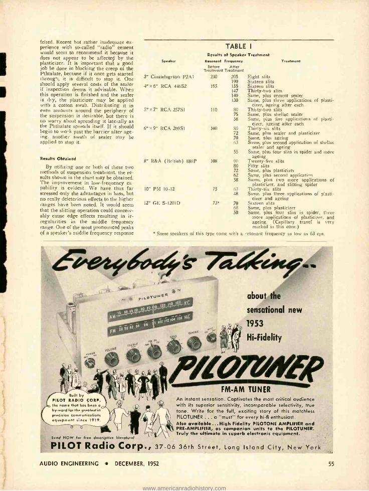
felted. Recent but rather inadequate ex- perience with so- tailed "radio" cement would seem to recommend it because it does not appear to be affected by the plasticizer. It is important that a good job be done in blocking the creep of the Pthtalate, because if it once gets started through, it is difficult to stop it. One should apply several costs of the sealer if inspection deems it advisable. When this operation is finished and the sealer is dry, the plasticizer may be applied with a cotton swab. Distributing it in even amounts around the periphery of the suspension is desirable, but there is no worry about spreading it laterally as the Phthalate spreads itself. If it should begin to work past the barrier after age- ing. another swath of sealer may be applied to stop it.
Results Obtained
By utilizing one or both of these two methods of suspension treatment, the re- sults shown in the chart may be obtained. The improvement in low- frequency ca- pability is evident. We have thus far stressed only the advantages in bass, but no really deleterious effects to the higher ranges have been noted. It would seem that the slitting operation could conceiv- ably cause edge effects resulting in ir- regularities in the middle frequency range. One of the most pronounced peaks of a speaker's middle frequency response
TABLE I
Results of Speaker Treatment Speaker Resonant Frequency Treatment
Before After Treatment Treatment
3" Cinaudagraph P2A1 230 205 Eight slits 190 Sixteen slits
4" x 6" RCA 446S2 195 155 Sixteen slits 147 Thirty -two slits 140 Same, plus cement sealer 130 Same, plus three applications of plasti-
cizer, ageing after each 5" x 7" RCA 257S1 110 80 Thirty -two slits
75 Same, plus shellac sealer 58 Same, plus five applications of plasti-
cizer, ageing after each 6 "x9" RCA 269S1 100 80 Thirty -six slits
72 Same, plus sealer and plasticizer 70 Same, plus ageing 63 Same, plus second application of shellac
sealer and ageing 55 Same, plus four slits in spider and more
ageing 8" R &A (British) 880P 108 90 Twenty -five slits
80 Fifty slits 72 Same, plus plasticizer 62 Same, plus second application 58 Same, plus two more applications of
plasticizer, and slitting spider 10" PM 10-12 75 63 Thirty -six slits
48 Same, plus three applications of plasti- cizer and ageing
12" GE S-1201D 73* 70 Sixteen slits 68 Same, plus plasticizer 50 Same, plus four slits in spider, three
more applications of plasticizer, and ageing. (Capillary travel is very marked in this cone.)
* Snim speakers of this type come with :I n nctilt frequency a, low as 63 cps.
770-6*ef_. . st AC.' pts.c.TUMEFt
r AM=T Iá9 MC
1 106 102 104
96 92 94 96
FM 86
TUNING
it ® VOlOMt
16011
about the
sensational new
1953
Hi- Fidelity
Built by PILOT RADIO CORP. the name that has been a by -word for the greatest in precision communications equipment since 1919.
rk Send NOW for free descriptive literature!
PILOT Radio Corp., 37 -06 36th Street, long Island City, New York
FM -AM TUNER An instant sensation. Captivates the most critical audience with its superior sensitivity, incomparable selectivity, true tone. Write for the full, exciting story of this matchless PILOTUNER ... a "must" for every hi -fi enthusiast. Also available...High Fidelity PILOTONE AMPLIFIER and PRE -AMPLIFIER, as companion units to the PILOTUNER-. Truly the ultimate in superb electronic equipment.
AUDIO ENGINEERING DECEMBER, 1952 55
www.americanradiohistory.com
In Stock at... fu/ BROWNING
HUDSON RV -31 FM TUNER RADIO L TELEVISION CORP.
The Newest and Finest in High -Fidelity at Lowest
Money Saving Prices!
NEW1953 NEW 1953
Hi-Fi Catalog
Hi -Fi Catalog
Complete new buying guide .. . value - packed with the world's finest High - Fidelity and Audio Equipment .
Amplifiers, Speakers, Tuners, Record Changers, Recorders, Packaged Systems, Custom Furniture, etc. for professional and home installation. Select from the largest stocks of ALL Standard Makes at LOWEST PRICES!
Send for your FREE Catalog Today!
for those who expect the exceptional
A new FM Tuner that gives you "real" realism, setting a new high in High -Fidelity reproduction. Genuine Armstrong Circuit with Automatic Fre- quency Control and temperature -compensated os- cillator provides drift -free, accurate tuning under almost any conditions. Small and compact for mounting in limited spaces; offers these great new features: New, all- triode RF section, for ex- tremely low noise level Higher sensitivity -3 microvolts for 20 db. quieting Cathode follower output stage, to feed any high -fidelity amplifier at low impedance Power outlets at rear. Has con- nection for phono, TV and recorder. 9 tubes plus tuning indicator and one rectifier. Dimensions: 642" H., 11" W., 9" D. Net $97.50
VISIT OUR SOUND STUDIOS
See! Hear! Compare! by simple push button remote control, over 15,000 combinations of nationally famous high -fidelity components.
Dept. D -12
48 WEST 48th ST. 212 FULTON ST. New York 36, N. Y. New York 7, h
Circle 6.4060
Git iLOdA<
The 2nd Audio Anthology Ready about November I
No bigger, no better than the original Audio Anthology -in fact, it's just the same size and a
perfect companion to the most authoritative book you now have on the subject of home music sys- tems. But it contains all new material- reprints of over forty of the valuable articles which have most interested Æ's readers during the past two and a
half years. Advance orders are now being accepted -so
make sure that you get your copy from the first printing. The board -cover edition will be printed in only a sufficient quantity to fill the advance orders -after that, only the paper- covered edition will be available.
Customary discounts to distributors.
Board Cover .... $3.00 Paper Cover
Features- Amplifiers
Preamplifiers
Tone Controls
Phonograph Equipment
Loudspeakers
Speaker Enclosures
Tape Recorder Amplifiers
UT OUT -MAIL TODAY
$2.00
Book Division, Radio Magazines, Inc., P. 0. Box 629, Mineola, N. Y.
Sirs: Enclosed is my check money order for 2nd Audio Anthology.
(Please check one) Board Cover Paper Cover
copies of the
Name (print carefully)
Address
City Zone State
is due to the resonance of the edges The mechanical alteration of the edge might aggravate the peak somewhat on the less expensive speakers. A small change in frequency of some of the peaks in a loudspeaker's curve has at times been observed, but the extent of the varia- tions has not been quantitatively ascer- tained because of the apparent inconse- quence. The plasticizer, however, would have no pernicious effect as long as it is kept within its prescribed area. If one were treating a speaker intended only as a woofer, there is nothing to lose in the complete treatment and much to gain. If both methods are applied, the slitting operation must be done first be- cause slitting a plasticized rim is quite difficult.
In checking progress the circuit shown in Fig. 3 has advantages. The 60 -cps 'scope input is used to calibrate the audio oscillator, an operation which should be performed at frequent intervals, particu- larly with a beat -frequency oscillator When working with low frequencies and such small increments, accuracy of cali- bration is important. By setting the oscil- lator to 60 cps and varying the calibra- tion adjustment until a stationary one - to-one Lissajous figure is obtained (cir- cle, ellipse, or inclined line, depending on phase), the oscillator can be set read- ily without much trouble. To find the resonant frequency of the speaker turn the 60 -cps input gain to zero and hold the speaker up in the air. Vary the fre- quency of the oscillator until the maxi- mum deflection is noted on the 'scope. The frequency indicated by the dial is the resonant frequency. In most cases it can also be detected audibly by noticing when the cone tends to chatter, which is caused by its greater displacement at resonance. The 'scope method, which depends on the rise in speaker impedance at its resonant frequency, is reliable and can also be used for a speaker mounted in a baffle thus serving to indicate the reduction in bass range that the enclosure might cause.
As a before -and -after test of this treat- ment, LP records with low organ notes* are very useful. Often the improved speaker will bring out notes in the lower register which were not even noticed be- fore treatment.
s Corrington and Kidd -"Measurements on loudspeaker cones," Proc. I.R.E. Sept. 1951, p. 1021.
4 Columbia ML 4120 : Saint Saéns, Sym- phony No. 3; Columbia ML 4329: Poulenc, Concerto in G Minor are good examples.
ERRATA
October issue, page 92 We are advised by Edward J. Gately,
Jr. that the dimension along the top of the cabinet of Fig. 2 should be y/ V 2 instead of ;y as shown.
November issue, page 23 We are advised by George Ellis Jones,
Jr. that the screen -to- ground resistor, Rse, associated with V, should be 10,000 ohms instead of 1000 ohms as shown in Fig. 5. The correct value is shown in the parts list on page 79.
56 AUDIO ENGINEERING DECEMBER, 1952
www.americanradiohistory.com

WIDE -ANGLE DISPERSION [from page 25]
and then suddenly releasing the wave front in that very same plane, it becomes possible to flare the horn more suddenly near its mouth, which will result in wider dispersion. Second, by choosing the point at which wave front restriction changes direction, it is possible to ar- rive at a vertical mouth opening of sufficient size to control the vertical directivity as desired.
Since the angular dispersion is a par- tial function of the geometric distribu- tion of pressure within the horn, the reverse -flare horn must be examined geometrically. Figure 3 indicates the cross -sectional area distribution of the reverse -flare horn. The horn is, at all times, exponential. Regardless of the shape of the cross -section, one area progresses from the preceding area in a logarithmic fashion with distance x, bounded strictly by the cut -off frequency for which the horn is designed. Since these areas are the product of the ver- tical and the horizontal dimensions, the horizontal dimension may be chosen to have any desired value. This will per- mit primary restriction of the wave ex- pansion to be made as severe as desired. If the horizontal dimension is to be kept unchanged from the smallest value as found at the throat of the horn, it will simply mean that the vertical height will do all the expanding. Or if it is desired to let the horizontal dimension expand slightly, then the vertical height need not expand as rapidly. The cross -sec- tional area may be proportioned in any way best suited to the desired result.
The purpose for the present is ac- tually to restrict early horizontal spread of the wave front within the horn, but to allow the wave front to expand freely in the vertical direction, within the horn. Restriction of the wave front expansion from the horizontal plane gives rise to an area of high wave -front pressures against the restraining vertical walls. Conversely, freedom of the wave to ex- pand in the vertical direction will result in minimum wave -front pressures against the fast flaring upper and lower walls. As an analogy, picture a cylindri- cal tube in which two inserted pistons confine a gas under pressure. When these pistons are stationary, the con- fined gas pressure is equally distributed over the walls of the tube and the piston faces. If the pistons are now suddenly pulled apart, the confined gas pressure will tend to expand toward the piston faces. If the pistons retreat fast enough, the expanding gas may never catch up to them. Consequently, these retreating pistons, which allow the gas to expand in their direction, will have minimum pressure exerted upon them, whereas the restraining walls of the tube will ex- perience the greater gas pressure.
Returning to the horn walls, the dif- ference in wave front pressures against the vertical walls and the top and bottom walls may be represented graphically,
as shown in Fig. 4. This pressure configuration rep- resents the state of affairs concerning the internal pressures against the horn walls extending from the throat of the horn down to the point at which it may be desired arbitrarily to reserve the pressure distri- bution. For the moment, let any such point be chosen along the horn axis at which to introduce this pressure reversal.
Fig. 5. Flare reversal of the horn walls turns the direction of the wave -front expansion from vertiol to horizontal.
Such a desired pressure reversal may of the upper and lower walls which have be accomplished by restricting the flare been expanding, simultaneously flaring
professional tape recorders for home Give your family the realistic brilliance of high fidelity tape recordings right in your own home! Your favorite AM and FM radio programs - the voices of your children and family friends - can be faithfully preserved and replayed for your listening pleasure. Professional in quality, yet priced within reach, MagneCordette represents the utmost in magnetic recording for the home. Start a family "sound library" today, for enjoyment in the years ahead. sue..
C/ï 1//Foe the first lime, Magnecordings by Vox,
finest tape recordings by world - famous artists for replaying on your MagneCordeu. ! Greater fidelity and tonal purity Iban could evre be obtained on disc recordings! Hear them at your Mag- necord dealer's.
AUDIO ENGINEERING DECEMBER, 1952
and office
The magn comes in
a rich blond or rich, dark mahogany finish cabinet, to match any decor. Priced at only $395. For a demonstration, see your Classified Telephone directory under "Recorders." magnecord, Inc. Dept. AE -12, 225 W. Ohio St., Chicago 10, Illinois
57
www.americanradiohistory.com
"WHOLESALE RADIO"
For ALL The BEST In
HI -FI SENSATIONAL
High Fidelity PACKAGE SPECIAL Complete! Nothing Else to Buy!
Famous
MEISSNER 9AJ AM -FM
TUNER Indentical to equipment built to sell for twice the price. Complete provision for phono input. All controls on front panel. High selectivity and sensitivity. Full audio fidelity. Drift proof FM. Full tone control. Built -in phono switching. Power outlet for phono motor. Air wound FM coils. Automatic volume control circuit. Almost unbelievable high fidelity and tonal richness. 7 miniature tubes plus power amplifier and rectifier.
BELL
AMPLIFIER Model 2122
Superb high- fidelity performance. Excellent for reproduc- ing the extended range of microgroove
records and FM. Frequency response 3 db 30 to 15,000 cycles with controls set for flat re- sponse. Four inputs: radio, crystal, and two magnetic pickups with built -in pre -amp for each Bass and treble boost with attenuation. Power; I7V. 60 cycles. Size; 71/2" deep, 6" high, 111/2" long.
VM Tri -O -Matic 3 speed
RECORD
CHANGER VM model 951 GE with General Electric RPX -050 cartridge. Plays all records, all speeds, all sizes, all types completely automatically and stops automatically after the last record. Records are lowered, not dropped on spindle shelf. No wobble, scrape, or slap . . . no center hole wear.
GENERAL ELECTRIC SPEAKER
Model 5- 1201 -D
GE high fidelity 12" speaker to deliver true faithfulness from your Hi- fidelity system. Frequency response: 50 -
13,000 cps. Power handling capacity 25 watts. 8 ohms Impedance. Alnico V. PM.
Address Orders To Dept AF 12
Write For Free F.Y.I. Folder
WHOLESALE 1 RADIO PARTS CO., Inc. 311 W. Baltimore St.
BALTIMORE 1, MD.
58
out the vertical walls which up to now have not been flared. This will permit the side thrust pressures which have been built up against these vertical walls, to suddenly burst out of their restrain- ing shell, so to speak, and to be impelled actively along the direction of the new flare. This action is illustrated in Fig. 5. In Section A of the horn all the wave expansion is in the vertical direction, with wave restriction in the horizontal direction. At these restraining walls there is a resultant boundary of in- creased pressure. After section X -X, Y -Y, the portion of the horn indicated as B now flares rapidly in the horizontal direction, while in the vertical direction there is practically no flare. Because the wave front can no longer expand vertically, pressure will be built up against these upper and lower walls. On the other hand, since the wave is allowed to expand horizontally, the pressure will dissipate itself over the horizontal angle. Thus, the pressure reversal has been accomplished.
Because of this pressure reversal, the dispersion gain in the horizontal direc- tion is two -fold. The first element of gain obtains from the manner that the B section of the horn is energized. It is quite permissible to consider section Y -Y as being the throat for a new horn B, and that the sound source which feeds this horn to be the mouth X -X of horn A. This new sound source X -X is one in which the driving pressure is greatest in the direction of ultimate dis- persion, that is, in the horizontal direc- tion. Thus the sound source is "matched" on a pressure configuration basis to the shape of the horn which is to disperse that pressure. Increased pressure dis- persion is thus obtained as compared with the case where the throat of the horn is fed from a source of symmetrical pressure distribution.
The second element of gain stems from the much greater flare possible near the mouth of the horn, where it counts most. By allowing but little hori- zontal expansion prior to the point of pressure reversal, and suddenly limiting the vertical expansion severely after the point of expansion, it becomes possible
ustt t be
ition
,AITf,R
1220 pages 80,000 items 8,000 illustrations 8 "zl1" -Slbs.
Publisher's price $6.50 -your pp e
through your Sr regular party distributor
/41DCOLP SOLDERING
INSTRUMENTS Any Voltage Range Supplied from 6/7 to 230/250 volts.
Our instruments for 110 volts are superb in making
SOUND JOINTS
for all
SOUND EQUIPMENT
Supplied to leading British electrical manufacturers and H.M. and foreign govern- ment departments.
These soldering instruments are named instruments as they are such a complete departure in design from the usual solder bolt or iron and are ideal for all modern assembly and maintenance work on telecommunica- tions, radar, television, wire- less, etc. 3/16" dia. bit Standard
Models 3/16" Detachable Bit Type
(Factory Bench Line) Heating time: 90 seconds Consumption: 25 watts Weight: 4 ozs. High temperature Handle unaffected by element temperature Length of Instrument: 9" Equally suitable for daily or intermittent use Prices ex Works.
Standard 3/16" Bit Model $3.60 Standard 1/4" Bit Model 4.00 Detachable 3/16" Bit Model 4.80
Catalogue sent free on request. MADE IN ENGLAND
Registered Designs (U.S.A., British, 1a Foreign Patents)
Write direct to sole manufacturers and suppliers:
ADCOLA PRODUCTS, LTD. CRANMER COURT
CLAPHAM HIGH STREET LONDON, S.W. 4, ENGLAND
The right part when you need it for production or laboratory requirements This permanent, hard cover Official Buying Guide of the electronic -TV parts and equip- ment industry with its comprehensive de- tailed index, eliminates the need for main- taining files of small catalogs and manufac- turers' literature.RADIO'S MASTER catalogs 90% of TV and electronic equipment. Not merely part number listings - complete descriptions, specifications and illus- trations written and compiled by each manu- facturer. Enables you to make comparisons or substitutions right now!
INITO CATALOG PIIILISIEIS, INC. I10 Lofw.a. St., Now York 13
AUDIO ENGINEERING DECEMBER, 1952
www.americanradiohistory.com
thereafter to throw all the desired ex- ponential expansion into the horizontal direction near the mouth end of the horn. As a result of this terminal ex- pansion, the horn will expand much faster in the horizontal direction than would be the case if the horizontal ex- pansion were to have started back at the original horn throat. The end effect of this faster physical flare for the new short horn section is an increased dis- persion angle for the high frequencies.
Having thus accomplished wide -angle dispersion of the radiated sound into the horizontal direction by means of flare control, one additional step may be taken to prevent undue dispersion or diffraction effects into the vertical direc- tion. Such control may be obtained in two ways. Just as low flare will produce relatively narrow dispersion, so a large mouth will reduce diffraction. We al- ready have a slow flare in the vertical direction because of the vertical flare restriction near the mouth of the horn. Consequently, half the problem of re- stricting the vertical dispersion is al- ready taken care of. The second con- trolling factor, that of mouth size in the vertical direction, may be obtained if that dimension is permitted to become at least one -third of the wavelength of the lowest frequency to be radiated.
Such a condition is accomplished in these reverse -flare horns by locating the point of flare reversal where the vertical dimension is close to the desired vertical mouth height, and from this point on providing but slight vertical expansion. By such dimensional manipttlation it is possible to terminate the horn in a square horn mouth, the vertical height of which is sufficiently large to reduce diffraction in the vertical plane to a minimum.
The end result of this flare reversal may be summed up as follows: The mouth end of the horn is transformed into a much faster flare in the horizontal direction; the pressure configuration within the horn is altered to match the flare distribution; the vertical mouth size is proportioned to provide minimum diffraction and dispersion. This three - way attack on the problem of high -fre- quency distribution produces a family of horns which exhibit a high degree of dispersion efficiency.
Book Review HANDBOOK OF ENGINEERING FUNDAMEN-
TALS, Second Edition, edited by Ovid W. Eshbach. 1270 + x + 52 pages, $10.00. New York: John Wiley & Sons, 1952.
Æ readers may well wonder why a re- view of this 1332 -page mine of information should find its way into the columns of their magazine. Little may they realize that nine of the 14 sections into which this book is divided have direct applica- tion upon their work.
Commencing with a formulary of math- ematical and physical data, the treatment proceeds with a section on mathematics, followed by one on physical units and standards wherein are capably covered the dimensional system as it applies to elec- trical and physical units and mensuration systems. Then follow sections on the me- chanics of rigid and deformable bodies, fluids, aerodynamics, and thermodynamics. electricity, radiation (covering light and acoustics), chemistry, metallic and non- metallic materials, and finally a most ex- cellently presented discourse on engineer- ing law completes the book, which is made easy to use by the 52 -page index.
Much of the material has appeared in print before, both in the first edition of this book and in some other engineering texts, but the staff of experts under Mr. Eshbach's able guidance has done an out- standing job of revising it and making the data current. The mathematical treatment will be of great use to those who have for- gotten some of the finer points learned in their school days, and to the engineer called upon to do some work in fields apart from his daily activities this text will lend a welcome helping hand. Coverage of such subjects as the radiation theories of light and sound, acoustic absorption and reflection, will come in handily in studio design as will those pages dealing with air conditioning, heating, and ventilation.
This is not a complete text, but it is certainly an adequate handbook -as such it well fulfills its mission. I would have preferred to see the use of continuous pagi- nation rather than that used -namely, each section receiving its own series of num- bers, but this is a minor criticism. To those who wish to augment their present li- braries with a single volume embracing the broad aspect of engineering funda- mentals for reference and daily use, this Handbook is well worth the cost and space it occupies.
-L. B. Keim
FULL TONAL REALISM
5llp .w&9z' LOUDSPEAKER ENCLOSURES
CLEANNESS . reproduction without resonant peaks or distortion...is the keynote of SUPER -HORN engineering. Full bass down to 40 cps. is accurately reproduced by an exponential horn. Clear highs are radiated directly from the front of the speaker with no tuned cavities or ports to produce false bass or "boom ".
GRACEFUL RIGIDITY is the keynote of SUPER -HORN construction. Classic beauty of line is combined with rugged durability. All panels ore of Vs inch and Mr inch woods, internally braced to prevent vibration.
BLOND..... 12" ... $80 -15" .. $85 MAHOGANY 12 "... $75 -15" .. $80
All Prices Net
WRITE FOR TECHNIC
GAT E LY DEVELOPMENT LABORATORY
CLIFTON HEIGHTS, PA.
ORDER NOW! 1952 Bound Volumes -$8.95
(Outside U.S.A. add 75 cents postage) Over the years AUDIO ENGINEERING has proven itself a valuable reference work worthy of a permanent place in your library. Many 1952 issues are already exhausted but you may have a complete bound volume of new copies for the entire year if you order now.
For the years to come - Subscribe to AUDIO ENGINEERING on the combination offer which includes a bound volume at the end of the year. Each month you receive the magazine by mail as usual -read it, cut out coupons to your heart's content, mark on the pages as much as you like. Around January 15, 1954, you receive a fresh, new, bound volume of 1953 issues-no creases, no dog -eared pages. The cost ? - only $10.00 per year, a saving of $1.95 over the price of the bound volume and the one -year subscription. Same offer, for two years, $18.50. (Canada and Pan -American Union -1 yr. $11.00 2 yrs. $20.00;
all other foreign -1 yr. $12.00, 2 yrs. 322.00)
Dept SV, AUDIO ENGINEERING, P. O. Box 629, Mineola, N. Y.
This offer expires February 1, 1953
El Enclosed is my check (or money order) for $ for .... copies of the 1952 Bound Volume of AUDIO ENGINEERING,
to be delivered about January 15, 1953.
U Enclosed is my check for money order) for $ for
a fl new renewal subscription for one year, plus a 1953 BoundVolume which will be delivered without further charges approximately January 15, 1954.
Enclosed is my check (or money order) for $ for a I-1 new renewal subscription for two years, plus a 1953
Bound Volume which will be delivered without further charges approximately January 15, 1954, and plus a 1954 Bound Volume to be delivered about January 15, 1955.
Name
Address
City Zone .... State
AUDIO ENGINEERING DECEMBER, 1952 59
www.americanradiohistory.com

Entering the Fair for the first time. Pilot Radio Corporation gave graphic evidence of the reasons for Its ascension to a position of leadership In the audio Industry within the space of one short year. Obvious to the high - fidelity hobbyist and audio engineer were the excellent design and performance features of the new Pllotuner and Pilot amplifiers - just as obvious to contemporaries and com- petitors was the adroit sales management of Adolph Gross, long known as one of the country's more astute merchandisers of electronic equipment.
From out Chicago way came Precision Electronics, Inc., with a thoroughly interest- ing display of the company's well -known Grommes amplifiers. The Grommes Model 50PG, incidentally, is probably the country's top seller in its price bracket. Although re- markably performing were the Grommes am- plifiers, equally impressive to this observer was the youthfulness of Precision's president, personable Bill Grommes. He, along with another Bill- Shrader of Washington -and Norman Pickering of Pickering and Com- pany, are great morale builders because they make the rest of us old- timers in the audio industry feel that- perhaps, after all -we do have an oat or two left.
Presto Recording Corporation, not too long ago known alone for its dise recording equip- ment, gave solid evidence that today its emi- nence in the tape recording field is just as pronounced. A thoroughly satisfying exhibit of fine recording equipment -both disc and tape -which meets highest professional standards.
The long -awaited Model 300 equalizer -pre- amplifier was the highlight of The Radio Craftsmen, Inc., exhibit. Sharing honors was the new Model C -800 AM -FM tuner. John Cashman, president of Radio Craftsmen, Inc., is doing the audio industry a great service with a national advertising campaign de- signed to show the many advantages of high fidelity for the average home. The first of these ads, a two -page spread in the Decem- ber issue of "House and Garden." features a statement by Deems Taylor, noted com- poser and critic. Would that more manu- facturers emulated this gesture, by stressing the advantages of high fidelity in general, along with advertising the merits of their own products.
The pride of Col. R. H. Ranger was more than Justified as he demonstrated the newest models of Rangertone tape recorders. As president of Rangertone, Inc., his is the guidance which has brought to the audio world a line of tape recording equipment which is unexcelled in the precision of its construction and the perfection of its per- formance. Strictly professional items, the Rangertone recorders are supreme examples of quality without compromise.
Diversity and expansion have been the year's keynote for Reeves Soundcraft Cor- poration- diversity in the sense that Magna- stripe, the Reeves- developed motion picture film on which is placed an oxide strip for magnetic recording, Is receiving increased sales effort, and expansion in the sense that sales of all Reeves products are on the up- grade. This exhibit tastefully displayed Magnastripe, as well as Soundcraft recording discs and tape -the overall emphasis being on the care and precision with which Reeves products are manufactured.
Even in an impersonal evaluation of ex- hibits, such as this is supposed to be, per- spective demands that tribute be paid certain personalities who have done their share and more toward creating national consciousness of high fidelity and the wealth of enjoyment it affords the American home. And so it is that we mention here the name of George Silber, president, The Rek -O -Hat Company, who as host in his firm's exhibit, never let up on the fight he pioneered to make the nation high -quality -audio conscious. It goes without saying that the showing of Rek -O- Kut turntables, disc recorders, and portable record players, was in keeping with the en- viable reputation the company commands throughout the audio world.
Making its initial bow before an Audio Fair audience, Revere Camera Company created great interest with a complete show - in of tape recorders suited essentially for adding sound to home movies. Special atten- tion was accorded the new Model T -10, a moderate -priced unit which closely approxi- matee the performance of many professional recorders. Among unique features of the T -10 is a built -in index counter which affords
AUDIO FAIR (from page 32)
quick location of any desired portion of a recorded reel.
Another Fair newcomer was River Edge Industries, River Edge, N. J. In every respect the River Edge display reflected the firm's advertising theme -"Audio's Finest Cabin- etry." Formerly devoted entirely to the manufacture of TV cabinets, River Edge today is one of the country's major suppliers of fine enclosures for home music systems.
An introductory showing of the British - made Collard record changer was featured in the display of Rockbar Corporation, Collaro's American distributor. Various models were arranged over mirrors, thus permitting visi- tors to inspect each changer through a com- plete playing cycle, and see for themselves the manner in which the Collaro operates.
Both professional and home equipment came in for just share of attention in the exhibit of Hermon Roamer Scott, Inc. Audio and acoustical engineers gathered around the famous Scott Sound Level Meters and the new Type 140 -A Decade amplifier, while music lovers found substantial interest in the various Scott amplifiers for home music systems. At the risk of being repetitious we are going to quote front last year's Audio Fair Review in which was expressed the thought that "the new Scott amplifiers are exceptional in the scope of equalization they provide for all types of recordings."
Probably the Fair's most varied display of tape recording equipment was that offered by Sonocraft Corporation, New York. Justi- fied was the company's reputation as one of the country's leading distributors of tape recorders to home and industry, with par- ticular emphasis on its representation among schools, colleges, and institutions. Sonocraft made many new friends through the gra- ciousness of its competent and likeable presi- dent Herbert H. Borchardt.
"Packaged High Fidelity" was the theme around which was built the exhibit of The Sound Workshop, a new company recently formed by Electronic Workshop Sales Cor- poration, New York, and G & H Wood Products Company, Brooklyn. Introduced were completely -assembled high -fidelity home music systems which compete in price with conventional radio- phonographs.
Excellent loudspeakers in tastefully de- signed enclosures -in a nutshell that's how we can summarize the exhibit of Stephens Manufacturing Company. At least that's the story from the music lover's viewpoint. For the audio pros there was the Stephens "wireless microphone" -the little gadget which permits TV and stage performers com- plete freedom of movement, and the studio - model Stephens condenser microphone for high -quality recording.
Among the more newsworthy of the Fair's exhibits was that of the Stromberg- Carlson Company. Here was shown the complete line of amplifiers, speakers and tuners introduced by a major manufacturer as a mark of recog- nition to the growing importance of the market for high-quality audio equipment. No stranger to the high- fidelity field. Stromberg years ago held a position of unquestioned leadership. Until recently, however, the com- pany's sound division has concentrated its production in public- address and industrial sound equipment. The superb performance of the new Stromberg units, developed under the able direction of chief engineer Frank Slaymaker, proves once more the truth in the adage "old masters never lose their touch."
Striking custom -built cabinetry shared at- tention with a lavish showing of equipment in the suite occupied by Sun Radio & Elec- tronics Company, New York. As if that weren't enough to assure a constantly -filled exhibit, Sun took no chances and provided its own crowd as well -the official program listing eighteen of the company's personnel as being in attendance. Thanks to an Im- pressive display, the precaution proved un- necessary -the SRO sign being in constant evidence.
Visitors to the tapeMaster, inc., suite were treated to a preview of a newly developed wide -range tape recorder which will make its appearance in dealers' showrooms as quickly as production can be established. It was this reporter's good fortune to hear the new tapeMaster model in competitive tests with recorders covering all price ranges -and here- with Is presented the consensus of one opin- ion that tapeMaster is coming up with a sure -fire winner.
In its initial Fair participation, Germany's Telefunken Company made news with an
inclusive display of radio receivers, ampli- fiers, speakers, and, of course. the noted Tele- funken condenser microphone. Long known as a world pioneer in the science of sound, Telefunken exhibited equipment well in keep- ing with the company's brilliant reputation.
As a result of visiting the Terminal Radio Corporation suite shortly prior to the Fair's official opening, this observer finds himself in possession of the first distributed copy of what is by all odds the largest and most complue catalog ever devoted solely to audio equipment. Whether you he amateur or pro, music lover or recording engineer, -no matter if you need an intercom system or an inter - modulation meter -you are certain to find it in this new Terminal catalog. Messers. Filler, Miller. Simon et al are to be thor- oughly congratulated on an unusual accom- plishment. Terminal's equipment display gave feature billing to the new Travis Tapak portable tape recorder.
The record changer to end all record changers was observed in the exhibit of Switzerland's Thorens Company. Along with standard models which play records in the usually prescribed manner, there was dem- onstrated a two- motored unit which, in ad- dition to intermixing. will follow almost any desired sequence. Thorens, you may re- call, manufactured the changer which was used in the RCA Westminster series of radio -phonographs which were marketed sev- eral years ago.
Lone tube manufacturer to exhibit at the Fair was Tung -Sol Electric, Inc., whose Type 5881 is just about the hottest thing you can get in output tubes. Many visitors (present company not excepted) left the Tung -Sol suite considerably better informed on the subject of tube design as a result of discus- sion with the firm's engineers.
Ultrasonic Corporation, manufacturers of the small corner- speaker assembly designed by Drs. Baruch and Lang of M. L T., offered demonstrations designed to verify for lis- teners the remarkable measurements of the unit made in the M. I. T. lab. According to an interview with the inventors which ap- peared in the New York Times, M. I. T. measurements of the speaker are claimed to prove its ability to reproduce fundamentals as low as 40 cps, although it occupies a space of only 2% cu. ft.
A new 20 -watt version of the famous Wil- liamson amplifier was featured in the exhibit of United Transformer Company. Quite natu- rally, it contained UTC transformers as did the 10 -watt Williamson with which it was compared. In addition to completed ampli- fiers, there was displayed an impressive selec- tion of UTC transformers for most every conceivable audio application.
Along with the hi -fi speakers for which the company is justly noted, University Loudspeakers, Inc., introduced a new line of speaker enclosures designed to complement both period and modern furnishings. With the introduction of the new cabinets, Uni- versity becomes one of the country's lending suppliers of complete speaker assemblies as well as individual components.
Visitors to the suite occupied by V -M Cor- poration were rewarded by a display of record changers of most every size and type. Popular in exhibit, as it is in sales. was the V -M changer with the "Siesta Switch " -an automatic means of turning off an entire music system at the conclusion of the final record on the changer.
There's no better example of recent growth in the audio industry than that afforded by Waveforms, Inc., whose display included the high -quality amplifier and miniature audio oscillator for which the company originally became noted, as well as a number of new test instruments which have been developed within the past year.
New impetus was given sales of the Weathers FM pickup with a dramatic dem- onstration which emphasized the virtual ab- sence of record wear due to the unit's 1 -gram playing pressure. Conducted by company president Paul Weathers, the weathers In- dustries exhibit was both effective and au- thoritative.
Webster- Chicago Corporation, in its initial Fair participation, displayed the firm's en- tire line of ` ebcor tape recorders, wire re- corders, portable phonographs, and record changers. Pioneer in the science of wire re- cording, Webcor retains a position of indus- try leadership -well evidenced by the sales records being racked up by the Model 235 office dictation machine.
60 AUDIO ENGINEERING DECEMBER, 1952
www.americanradiohistory.com
LOW NOISE, PRECISION
RESISTOR KIT for
Williamson -Type Amplifiers Hard -to- obtain, low -noise 1% precision resistors at reasonable prices.
These resistors are of the highest quality fresh stock, manufactured un- der WE license. The resistance ele- ment is pyrolytically deposited carbon bonded to a ceramic core. The kit contains the following resistors and data sheet.
Quan. Resistance Wattage Precision 1 47,000 1 1% 2 20,000 1 100 2 0.47 Meg 1/2 100 2 50,000 2 1% 2 0.1 Meg 1/z 1%
Price $5.00 Include 15e for postage and handling.
No COD. Quick delivery!
EDWIN BOHR Dayton Pike
Chattanooga 5, Tennessee
ELECTRONICS ENGINEER Group leader required to take charge of an electronics laboratory engaged in analyti- cal instrument development. Design ability in conventional circuitry as applied to a.c. and d.c. amplifiers, power supplies, light detection devices, thyratron circuits, dis- criminators, magnetic circuitry and frac- tional horse -power motors desirable.
Five years experience or advanced degrees in lieu of part of this experience required. The position is a permanent one with an old established instrument company who is a leader in the field.
Send resume with salary requirements to: Personnel Manager
Fisher Scientific Company 717 Forbes St., Pittsburgh 19. Pa.
PROFESSIONAL DIRECTORY
Custom -Built Equipment
U. S. Recording Co. 1121 Vermont Ave., Washington 5, D. C.
LIncoln 3-2705
In Southern California it's HOLLYWOOD ELECTRONICS
(in The Audio Mile) Distributors of Hi Fidelity Components Exclusively
Webster 3 -8208 7460 Melrose Ave. Hollywood 46, Calif
AUDIO ENGINEERING
AUDIO PAIR AFTERMATH ... Amaz- ing, the large number .f Chicagoans, both observera and exhibitors who were seen parading up and down New Yorker corri- dors-to wit, ... Chet Whardeld, director, Allied Radio Corporation sound depart- ment, who came to the Big City a couple of days before the Fair opened in order to visit jobber -friends ... John Margolin, sales manager, tapeMaster, inc., who also made advance appearance to acquaint distributors with new wide -range tape recorder for home music systems ... Bill Grommes, president, Precision Electronics, Inc., who surprised New York correspond- ents with his youthfulness . Maurice
m Meshbon, prominent Windy City artist and true dyed -in- the -wool audio hobbyist, who came to town to listen, listened, and left with binaural bees buzzing in his bonnet.
John Boyers, Spec Barker, and Dick Mc- Queen, all Magnecord, Inc., officials who were just about the busiest boys in town while arranging the binaural broadcasts on WQXR and associated FM Network
. Hari Kramer of Jensen Manufacturing Company, who did his usual excellent job of selling the assembled multitude on the many virtues of Triaxial and Triplex. . In other words, you could have called a meeting of the Windy City's audio leaders at any time, with little fear of not having a quorum.
N. Y. O. PAIR HIGHLIGHTS ... Larry Epstein, president, University Loud- speakers, Inc., beaming with full justifica- tion over impressive appearance of corn - pany's new speaker enclosures- enthu- siasm shared by Walter Godfrey whose River Edge Industries organization is handling the production chores . . Fred L. Onnow, sales manager for Telefunken products in the U. S., reports greatly stim- ulated interest in the firms condenser microphone as result of showing at The Fair ... Dave Roark, new ad manager for Audio & Video Products Corporation, reverted to type (he's an ex- announcer) and narrated the demonstration tape for Ampex stereophonic sound -so far has been recognized by only 98 per cent of his friends . . . Lew Goodfriend, one of the nation's more brilliant audio engineers, kept hopping by multi- duties -holding down a job, manning a Fair exhibit, and delivering technical paper before AES Conventions. . . . Ken Boothe, director of Audio -Video's Instrumentation Division elated at new business originating at the Fair.
FAIR HIGHLIGHTS PROM CITIES HERE AND YON . A. A. Ward, execu- tive vice- president, Altec Lansing Corpo- ration, Hollywood, gave what was prob- ably the Fair's most informal interview to Gene Smith, feature writer for the New York Herald Tribune -standing squarely between the sixth -floor elevators and the registration desks; others who partici- pated in the same article -although tinder less trying circumstances -were Tony Etohiano of Stromberg- Carlson, Tom Nicholson of General Electric, and Leon- ard Cardnner of British Industries Corpo- ration . . . Prank McIntosh and friend - competitor Lincoln Walsh, designers and manufacturers of the McIntosh and Brunk amplifiers, respectively, surprised Fair visitors (and each other) when each in- troduced a new corner speaker.... Larry Lelashman of Electro- Voice, Inc., Bu- chanan, Mich., used most effective means of introducing firm's new Lavalier micro- phone -wore one throughout the show.
MISCELLANY . Genial Ed Cornfield has Joined sales staff of Adolph L. Gross Associates, Inc., New York factory reps- a nicer guy never lived . . . Edward H. Gillette, executive veepee of Allied Con- trol Company, Inc., announces appoint- ment of R. A. Yates as head of newly - formed new products division . Major General Edmond H. Leavey, U.S.A. (Re- tired), is newest veepee of I. T. and T. . . Edward A. Mailing has been appointed manager of marketing for Components Department of General Electric Company William W. Dean at one time con- tributor to columns of Æ, has been ap- pointed director of engineering of the Langevin Manufacturing Corporation .
Dr. Martin L. Klein, former member of University of Pennsylvania and Stanford University faculties is new addition to the engineering staff of Stancil- Hoffman Corporation . . George L Long, general manager of Ampex Electric Corporation, Redwood City, Calif., announces promo- tion of Harrison Johnston to general sales manager . Dr. David B. Parkinson is new production engineering head of Brush Development Company . . John Jacks has Joined sales staff in sound depart- ment of Chicago's Newark Electric Com- pany -will assist Carl James, who heads up Newark's audio activities.
DECEMBER, 1952
HEADQUARTERS FOR
SOUND EQUIPMENT
COMPLETE LINE OF
COMMERCIAL AND
INDUSTRIAL SYSTEMS
McINTOSH 50 W -2 AMPLIFIER
Largest stocc of High Quality Amplifiers, from small single units to large rack installa- tions
likt-16" SOUND AND RECORDING CO. 1527 CHESTNUT ST.
PHILA. 2, PA. RI -6 -8388
A MPERITE Studio Microphones
at P.A. Prices
Ideal for BROADCASTING
RECORDING
PUBLIC ADDRESS "The ultimate in micro- phone quality," says Evan Rushing, sound engineer of the Hotel New Yorker.
Shout right into the new Amperite Micro - phone-or stand 2 feel away - reproduction is
always perfect. Not affected by
any climatic conditions. Guaranteed to with-
stand severe "knocking around."
1 h Models
RBLG -200 ohms RBHG -Hi -imp.
List $42.00
"Kontok" Mikes Modal SKH, list $12.00 Model KKH, list $18.00
ml introductory OBer. Write for Spec
Offer: and 4 -page illustrated folder.
AMP£R /TEGmpany inc. 561 BROADWAY NEW YORK 12. N. Y.
Canada, Anas Radio Corp., Ltd ?.60 King St. W., Toronto
61
www.americanradiohistory.com

Audio Engineering
AES Convention Program, Oct., 58. AES Papers
Magnetic Audio Amplifier Fundamentals, A. M. Vincent. Sept., 42.
No Coded Signals, H. S. Morris. Oct., 40. The Problems of Low -Frequency Reproduis
tion, Saul J. White. Apr., 20. Wide -Angle Dispersion of High. Frequency
Sound, Abraham B. Cohen. Dec., 24. Amplifiers
Commercial O -T -L Amplifier of Unique De. sign, Frank H. Gilbert. Aug., 46.
Gilding the Lily, David Sarser and Melvin C. Sprinkle. July, 13.
Integrated Line of Hi -Fi Equipment, Frank H. Slaymaker. July, 26.
The Maestro -a POWER Amplifier, David Sarser and Melvin C. Sprinkle. Nov., 19.
Magnetic Audio Amplifier Fundamentals, (AES Paper), A. M. Vincent. Sept., 42.
Neutralizing Hum and Regeneration, Arthur L. Hammond. May, 22.
New Medium -Cost Amplifier of Unusual Per- formance, C. Leonard Werner and Henry Berlin. Nov., 30.
New Newcomb Line Features New Features, Aug., 40.
The Output -Transformer -Less Amplifier. Vic- tor Brociner and Gerald Shirley. June, 21.
Speech Clipper Aids Station Performance, R. S. Houston. Nov., 50.
Ultra- Linear Operation of a Williamson Am- plifier, David Hafier and Herbert I. Keroes. June. 26.
Universal Amplifier for Magnetic Tape Re- corder, C. G. McProud. I, May, 17; II, June, 24; III, July, 22.
Williamson -Type Amplifier Up-To -Date. M. V. Kiebert, Jr. Aug., 18.
Amplifiers. Pre - Preamplifier for Critical Listening, M. V.
Kiebert, Jr. Sept.. 21. Two Preamplifiers for Magnetic Pickups,
George Ellis Jones, Jr. Jan., 24. Audio Fair. The
Exhibitor Directory. Nov., 54. The Audio Fair in Review. Dec., 26. The Audio Fair in Chicago. July. 24. Preview of 1952 Audio Fair. Oct., 58.
Audio Techniques Broadcast Short -Cuts, R. S. Houston. Apr.,
34. Improved Cathode Bias Circuit Affording
Fixed Bias, John A. Mulvey. Mar., 63.
Book Reviews Electrical Measurements, Forest K. Harris.
May, 44. Handbook of Engineering Fundamentals, Edit.
by Ovid W. Eshbach. Dec., 59. Make Music Live, Irving Greene, James R.
Radcliffe, Robert Scharff. Feb., 39. Musical Engineering, Harry F. Olson. Aug.,
9. Pianos, Pianists, and Sonica, G. A. Briggs.
Apr.. 8. Radio and Television Receiver Circuitry and
Operation, A. A. Ghirardi and J. Richard Johnson. Apr., 8.
The Recording and Reproduction of Sound, Oliver B. Read. May. 45.
Television Engineering, Donald Fink. Oct., 17. Television Explained, W. E. Miller. Oct.. 17. Television Principles, Robert B. Dome. Oct.,
17. Time Bases, O. S. Puckle. May, 45. Ultrasonics, P. Vigoureux. Sept., 68. Vacuum -Tube Voltmeters, John F. Rider and
Alfred W. Barber. Sept., 68.
Broadcasting Broadcast Audio Wiring Practices, W. Earl
Stewart. Aug.. 16. Broadcast Short -Cuts, R. S. Houston. Apr.,
34.
SUBJECT INDEX
Planning and Building a Radio Studio, Eu- gene F. Coriell. I, June, IS; II, July, 19; III, Aug., 22; IV, Sept.. 30; V, Oct., 30.
Speech Clipper Aids Station Performance, R. S. Houston. Nov., 50.
A Twin -Channel Utility Amplifier, R. S. Houston.. Apr., 17.
Binaural Sound Stereophonic Reproduction, James Moir. Oct.,
26.
Cabinets and Enclosures Cabinet Design for Hi -Fi Systems, Jeff Mar -
kell. May, 26. A Corner -Mounting Infinite Baffle, M. V.
Kiebert, Jr. Oct., 32. Design and Construction of Horn-Type Loud-
speakers, Wayne B. Denny. I, Mar., 22; II, Apr., 18.
Design for Clean Bass, Edward J. Gately, Jr. Oct., 29.
Design for Smooth Response, Vern Yeich. Jan., 15.
Horn- Loaded Bass Speaker, Earl R. Meiss- ner and L. K. Andrews. Jan., 22.
New Approach in Loudspeaker Enclosures, John E. Karlson. Sept.. 26.
Components How Good is an Audio Transformer, N. H.
Crowhurst. Mar., 20. Measuring up an Audio Transformer, N. H.
Crowhurst. Nov., 24. Some Pickup Design Considerations, P. G.
A. H. Voigt. Oct., 64. Connsonata Organ Installation for the 1952
Presidential Nominating Conventions, Serge L. Krauss and Karl Kramer. Dec., 15.
Controls Cathode- Follower Audio Control System,
Gladden B. Houck. Nov., 32. The Design of Compensated Volume Con-
trols, Emerick Toth. I, Jan., 13; II, Feb., 14.
A Proposed Solution to the Loudness Control Problem, John R. Schjelderup. Sept., 34.
Demonstration Techniques. Harrie K. Richard- son. Oct., 84.
Distortion. Intermodulation. Richard C. Hitch. cock. Oct., 21.
Dividing Networks, Discussion of. J. F. Went- worth. Dec., 17.
Equalisers, Design Simplified. George O. Doug- las. Dec.. 18.
Equipment Report Altec A -333 -A and A- 433 -A. Apr., 32. Bell 2145A. Mar., 30. Heathkit Williamson -Type Amplifier. May, 28.
Exhibits Audio Fair Exhibitor Directory. Nov., 54. Preview of 1952 Audio Fair. Oct., 58. The Audio Fair in Review. Dec., 26. The Audio Fair in Chicago. July, 24. The I.R.E. Show Review. Apr., 26. London Letter- British National Radio Ex-
hibition, Leonard Carduner. Oct., 12. NARTB Conference and Exhibit. May, 30. WESCON Exhibitors. Aug., 26.
Fantasy The Frudd Audio System, D. B. Frudd. Nov.,
12. The Golden Ear, Don V. R. Drenner. Nov..
81. Feedback
A Critical Feedback Analysis, Harold Klim- pel. Oct.. 23.
It's Positive Feedback, Warner Clements. May, 20.
Further Discussion on Positive Current Feed. back, Ulric J. Childs. May, 21.
Loudspeaker Damping with Dynamic Nega. tive Feedback, Ulric J. Childs. Feb., 11.
Filters, Record Improvement with H -F Cut -off; Elliott W. Markow. Nov., 27.
1952
Handbook of Sound Reproduction, Edgar M. Vipchur. I, June, 18; II, July, 15; III, Aug.. 20; IV, Sept., 38; V, Oct., 36; VI, Nov.. 40; VII, Dec., 20.
Home Music Systems Audio in the Home, William C. Shrader. I,
Jan., 18; II, Feb., 18; III, Mar., 47; IV, Apr., 24; V, June. 28; VI, July, 30; VII. Aug., 24.
Be Your Own Custom -Builder, Jay Carver and Clif Howard. Mar., 24.
Cathode Follower Audio Control System, Gladden B. Houck. Nov., 32.
How to Use Magnetic Pickups, Ulric J. Childs. Mar., 35.
Music's the Thing, Irving Greene and Mel- vin C. Sprinkle. Jan., 20.
On a Budget, Jay Carver and Clif Howard. May, 24.
Use Your Present Tuner, Ulric J. Childs. Apr., 29.
Legal Problems Trade Secrets and Their Protection, A. W.
Gray. Nov., 29. Loudness Controls
A Proposed Solution to the Loudness Con- trol Problem, John R. Schjelderup. Sept., 34.
The Design of Compensated Volume Con- trols, Emerick Toth. I, Jan., 13; II, Feb., 14.
Loudspeakers A Corner- Mounting Infinite Baffle, M. V.
Kiebert, Jr. Oct., 32. Design Considerations of Duplex Loudspeak-
ers, Alexis Badmieff. Sept.. 28. Design and Construction of Horn -Type Loud-
speakers, Wayne B. Denny. I, Mar., 22; II, Apr., 18.
Design for Clean Bass, Edward J. Gately, Jr. Oct., 29.
Design for Smooth Response, Vern Yeich. Jan., 15.
Discussion of Dividing Networks, J. F. Went- worth. Dec., 17.
Horn- Loaded Bass Speaker, Earl R. Meiss- ner and L. K. Andrews. Jan., 22.
Integrated Line of Hi -Fi Equipment, Frank H. Slaymaker. July, 26.
Loudspeaker Damping with Dynamic Nega- tive Feedback, Ulric J. Childs. Feb., I1.
New Approach in Loudspeaker Enclosures, John E. Karlson. Sept., 26.
New The Super Tweeter, Ralph P. Glover and Karl Kramer. Apr., 22.
The Problems of Low -Frequency Reproduc- tion (AES Paper), Saul J. White. Apr., 20.
Speaker Treatment for Improved Bass, R. Cameron Barritt. Dec., 23.
Wide -Angle Dispersion of H -F Sound (AES Paper), Abraham B. Cohen. Dec.. 24.
Measurements A Distortionless Oscillator, Dunford A. Kelly.
Aug.. 13. Intermodulation Distortion, Richard C. Hitch-
cock. Oct., 21. Linear -Scale A -F Wattmeter, C. G. McProud.
Feb., 17. Theory and Construction of a Harmonic Dis-
tortion Meter. George Ellis Jones, Jr. Nov., 22.
Microphone Technique -The Traveling Mike. N. H. Crowhurst. Feb., 16.
Musical Instruments -The Violin. Albert Preis - man. I, Sept., 24; II, Oct., 34; III, Nov., 36.
Phonograph Records, The Best British of 1950- 1951, H. A. Hartley. I, Mar., 28; II, Apr.. 50.
Phonograph Reproduction How to Use Magnetic Pickups, Ulric J.
Childs. Mar., 35.
62 AUDIO ENGINEERING DECEMBER, 1952
i
www.americanradiohistory.com

Phono Facts -1952. Maximilian Weil. June. 30.
Pickup Tracking Error, Edgar M. Villchur. Mar., 17.
Record Improvement with H.F. Cut -Off Fil- ters, Elliott W. Markow. Nov., 27.
Some Pickup Design Considerations, P. G. A. H. Voigt. Oct., 64.
Two Preamplifiers for Magnetic Pickups, George Ellis Jones, Jr. Jan., 24.
Radio Tuners Integrated Line of Hi -Fi Equipment, Frank
H. Slaymaker. July, 26. Use Your Present Tuner, Ulric J. Childs.
Apr., 29.
Recording, Magnetic Azimuth Film Calibration, Michael Rettinger.
Apr., 15.
Limitations of Magnetic Tape, William S. Latham. Sept.. 19.
Magnetic Tape in Southwest Monuments, T. B. Noble. Aug., 44.
Tape Recorder Echo Effects, R. S. Houston. Oct., 52.
Universal Amplifier for Magnetic Tape Re- corder, C. G. McProud. I, May, 17; II, June, 24; III, July, 22.
Using Hearing Characteristics in Tape Edit- ing, Joel Tall. May, 15.
Sound Reproduction, Handbook of. Edgar M. Villchur. I, June, 18; II, July, 15; III, Aug., 20; IV, Sept., 38; V, Oct., 36; VI, Nov., 40; VII, Dec., 20.
Stereophonic Reproduction, James Moir. Oct, 26.
Television -The Two Types of Theatre Video, John W. Sims. Jan., 16.
Transformers How Good is an Audio Transformer, N. H.
Crowhurst. Mar., 20. Measuring up an Audio Transformer, N. H.
Crowhurst. Nov. 24. The Violin, Albert Preisman. I, Sept., 24; II,
Oct., 34; III, Nov., 36.
Andrews, L. K., and Meissner, Earl R. Horn- Loaded Bass Speaker. Jan.. 22.
Badmieff, Alexis Design Considerations of Duplex Loudspeak-
ers. Sept.. 28. Barritt, R. Cameron
Speaker Treatment for Improved Bass. Dec., 23.
Berlin. Henry, and Werner, G. Leonard New Medium -Cost Amplifier of Unusual Per-
formance. Nov., 30. Brociner, Victor, and Shirley, Gerald
The Output -Transformer -Less Amplifier. June, 21.
Carduner, Leonard London Letter -British National Radio Ex.
hibition. Oct., 12. Carver, Jay, and Howard, Clif
Be Your Own Custom -Builder. Mar., 24. On a Budget. May, 24.
Childs, Ulric J. Further Discussion on Positive Current Feed.
back. May, 21. How to Use Magnetic Pickups. Mar., 35. Loudspeaker Damping with Dynamic Nega-
tive Feedback. Feb., 11. Use Your Present Tuner. Apr., 29.
Clements, Warner It's Positive Feedback. May, 20.
Cohen, Abraham B. Wide -Angle Dispersion of H -F Sound (AES
Paper). Dec., 24. Coriell, Eugene F.
Planning and Building a Radio Studio. I. June, 15; II, July, 19; III, Aug., 22; IV, Sept.. 30; V, Oct., 30.
Crowhurst, N. H. How Good is an Audio Transformer. Mar.,
20. Measuring up an Audio Transformer. Nov., 24. The Traveling Mike. Feb.. 16.
Denny, Wayne B. Design and Construction of Horn-Type Loud-
speakers. I, Mar., 22; II, Apr., 18. Douglas, George O.
Simplified Equalizer Design. Dec., 18. Drenner, Don V. R.
The Golden Ear. Nov., 81.
Frudd, D. B. The Frudd Audio System. Nov.. 12.
Gately, Edward J., Jr. Design for Clean Bass. Oct., 29.
Gilbert, Frank H. Commercial O -T -L Amplifier of Unique De-
sign. Aug., 46. Glover. Ralph P., and Kramer. Karl
New! The Super Tweeter. Apr.. 22. Gray, Albert Woodruff
Trade Secrets and Their Protection. Nov., 29. Greene, Irving, and Sprinkle, Melvin C.
Music's The Thing. Jan., 20.
Hafler, David, and Keroes, Herbert T.
Ultra -Linear Operation of a Williamson Am- plifier. June, 26.
Hammond, Arthur L. Neutralizing Hum and Regeneration. May, 22.
AUTHOR INDEX Hartley, H. A.
The Best British Records of 1950 -1951. I. Mar., 28; II, Apr., 50.
Hitchcock, Richard C. Intermodulation Distortion. Oct., 21.
Houck, Gladden B. Cathode- Follower Audio Control System.
Nov., 32. Houston. R. S.
Broadcast Short-Cuts. Apr., 34. Speech Clipper Aids Station Performance.
Nov.. 50. Tape Recorder Echo Effects. Oct 52. Twin -Channel Utility Amplifier. Apr., 17.
Howard, Clff, and Carver, jay Be Your Own Custom -Builder. Mar., 24. On a Budget. May, 24.
Jones, George Ellis, Jr. Theory and Construction of a Harmonic Dis-
tortion Meter. Nov., 22. Two Preamplifiers for Magnetic Pickups.
Jan., 24.
Karlson, John E. New Approach in Loudspeaker Enclosures.
Sept., 26. Kelly, Dunford A.
A Distortionless Oscillator. Aug., 13. Keroes, Herbert I., and Haller, David
Ultra- Linear Operation of a Williamson Am- plifier. June, 26.
Kiebert, M. V., Jr. A Corner -Mounting Infinite Baffle. Oct., 32. Preamplifier for Critical Listening. Sept., 21. Williamson -Type Amplifier Up -To -Date. Aug..
18. Klimpel, Harold
A Critical Feedback Analysis. Oct., 23. Kramer, Karl, and Glover, Ralph P.
New! The Super Tweeter. Apr., 22. Kramer, Karl, and Krauss, Serge L.
Connsonata Organ Installation for the 1952 Presidential Nominating Conventions. Dec., 15.
Krauss, Serge L., and Kramer, Karl Connsonata Organ Installation for the 1952
Presidential Nominating Conventions. Dec.. 15.
Latham, William S. Limitations of Magnetic Tape. Sept.. 19.
Markel, Jeff. Cabinet Design for Hi -Fi Systems. May, 26.
Markow, Elliott W. Record Improvement with H. F. Cut -Off Fil-
ters. Nov., 27. McProud, C. G.
Linear -Scale A -F Wattmeter. Feb., 17. Universal Amplifier for Magnetic Tape Re-
corder. I, May, 17; II, June, 24; III, July, 22.
Meissner. Earl R., and Andrews, L. K. Horn - Loaded Bass Speaker. Jan., 22.
Moir, James Stereophonic Reproduction. Oct.. 26.
Morris, H. S. No Coded Signals. (AES Paper.) Oct., 40.
Mulvey, John A. Improved Cathode Bias Circuit Affording
Fixed Bias. Mar., 63.
Noble, T. B. Magnetic Tape in Southwest Monuments.
Aug., 44.
Preisman, Albert The Violin. I, Sept., 24; II, Oct., 34; III,
Nov., 36.
Rettinger, Michael Azimuth Film Calibration. Apr., 15.
Richardson. Harris K. Demonstration Techniques. Oct., 84. The Audio Fair in Review. Dec., 26.
Sarser, David. and Sprinkle, Melvin C. Gilding the Lily. July, 13. The Maestro -a POWER Amplifier. Nov., 19.
Schjelderup, John R. A Proposed Solution to the Loudness Control
Problem. Sept., 34. Shirley, Gerald, and Brociner, Victor
The Output -Transformer -Less Amplifier. June. 21.
Shrader, William C. Audio in the Home. I, Jan., 18; II, Feb., 18; III, Mar., 47; IV, Apr. 24: V, June, 28;
VI. July, 30; VII, Aug., 24. Sims, John W.
The Two Types of Theatre Video. Jan., 16. Slaymaker, Frank H.
Integrated Line of Hi -Fi Equipment. July, 26.
Sprinkle, Melvin C., and Greene, Irving Music's the Thing. Jan., 20.
Sprinkle, Melvin C., and Sarser, David Gilding the Lily. July, 13. The Maestro -a POWER Amplifier. Nov., 19.
Stewart, W. Earl Broadcast Audio Wiring Practices. Aug., 16.
Tall, Joel Using Hearing Characteristics in Tape Edit-
ing. May. IS. Toth. Emerick
The Design of Compensated Volume Con- trols. I, Jan., 13; II, Feb., 14.
Villchur, Edgar M. Handbook of Sound Reproduction. I, June.
18; II, July, 15; III, Aug., 20; IV, Sept., 38; V, Oct., 36; VI, Nov., 40; VII, Dec., 20.
Pickup Tracking Error. Mar., 17. Vincent, A. M.
Magnetic Audio Amplifier Fundamentals. (AES Paper.) Sept., 42.
Voigt, P. G. A. H. Some Pickup Design Considerations. Oct..
64.
Weil, Maximilian Phono Facts -1952. June, 30.
Wentworth, J. F. Discussion of Dividing Networks. Dec.. 17.
Werner, G. Leonard, and Berlin, Henry New Medium -Cost Amplifier of Unusual Per-
formance. Nov., 30. White, Saul J.
The Problems of Low- Frequency Reproduc- tion. (AES Paper.) Apr., 20.
Teich, Vern Design for Smooth Response. Jan., 15.
AUDIO ENGINEERING DECEMBER, 1952 63
www.americanradiohistory.com

FAIR WEATHER AHEAD
The Audio Fair is over but its
results will persist. To all those
who helped to make our exhibit an
outstanding success -our agents, our customers, and those who now
want to be our customers -our very best thanks.
Our one and only problem is to
bring about a very quick increase in
production without impairing Hart- ley quality. The process has started and soon we shall be able to offer you, from stocks in the U.S.A., the
most intriguing and complete range
of audio equipment you could wish
for. The Fair showed that the 215
speaker still has nothing to fear from its more expensive rivals, but from all quarters we got the judg- ment that the Boffle is the most
nearly perfect housing for a nearly
perfect speaker. The Boffle is going into production in America.
So is our amplifier. We have not "plugged" it before since we are
fundamentally speaker manufac- turers; but again we have been told we must make it easy to acquire, because it is so good. That we shall do; and we think our prices for American produced equipment will be about the same as British. We consider this important for realistic audio should be within the reach of every man.
All on our mailing list will re- ceive full details of our plans and products. The inception of Ameri- can production will give us many
opportunities for introducing new
and exciting products. So, if your name is not on that list just send a
postcard asking us to put it on.
You can no longer afford to be without Hartley Audio.
H. A. HARTLEY CO. LTD. 152, Hammersmith Road
London W.6, England
6.1
ADVERTISING INDEX
Adcola Products, Ltd. 58
Air Tone Sound & Recording Co. 61
Allied Radio Corp. 53
Allied Sound Corp. 54
Altec Lansing Corp. 41
Amperite Co., Inc. 61
Ampex Electric Corp. 13
Amplifier Corp. of America 2
Arnold Engineering Co. 3
Arrow Electronics Inc. 40
Audak Co. 35
Audio Devices, Inc. Cover 2
Beam Instruments Corp. 48
Belden Mfg. Co. 7
Bell Telephone Laboratories 14
Bogen Co., Inc., David 51
Bohr, Edwin 61
Cannon Electric 37
Carter Motor Co. 50
Chicago Transformer Co. 39
Cinema Engineering Co. 52
Classified Ads 64
Driven Co. Cover 3
Fisher Scientific Co. 61
Garrard Sales Corp. 49
Gately Development Laboratory 59
General Hi Fi Co. 44
H. A. Hartley Co. Ltd. 64
Harvey Radio Co., Inc. 33
Heath Co. 53
Hollywood Electronics Co. 61
Hudson Radio & Television Corp. 56
Hughes Research & Development Lab- oratory 9
Lafayette Radio 38
Leonard Radio, Inc. 47
Magnecord, Inc. 57
Minnesota Mining & Mfg. Co. 31
Pickering & Co., Inc. 11
Pilot Radio Corp. 55
Precision Film Laboratories, Inc. 6
Professional Directory 61
Radio Corporation of Americo 8
Radio's Master 38
Reeves Soundcraft Corp. 5
Rek -O -Kut Co. 1
Rockbar Corp. 29
Standard Transformer Corp. 45
Tech -Master Products Co. 36
Thermador Electrical Mfg. Co. 50
Triad Transformer Mfg. Co. 12
Tung -Sol Electric Inc. 4
Turner Co. 43
United Catalog Publishers, Inc. 58
United Transformer Co. Cover 4
U.S. Recording Co. 61
University Loudspeakers, Inc. 54
Weathers Industries 51
Wholesale Radio Parts Co., Inc. 58
CLASSIFIED Rate,: 10e per word per insertion for noncommercial
advertisements; 25e per word for commercial adver-
tisements. Rates are net, and no discounts will be
allowed. Copy must be accompanied by remittance In
full, and must reach the New York of0ce by the
first of the month preceding the date of issue.
THE AUDIO EXCHANGE, INC. buys and sells quality high -fidelity sound systems and components.
Catalogue, Dept. used
, 159-19 Hillide Ave., Jamaica 32, N. Y. Telephone OL 8 -0445.
LONG ISLAND HIGH FIDELITY HEAD QUARTERS- Complete custom installations. Garrard changers, Bozak speakers, our own Williamson Amplifiers. Long Island Sound Co., 19 Bennett Place, Amityville, N. Y.
ANNOUNCING A NEW SERVICE -High- est quality discs cut from your tapes. All speeds -all sizes. Fairchild equipment, hot styli. Also monitoring off- the -air and special recording services. Reasonable rates. Write for prices. THE DUBBINGS CO., Dept. 12 -AE -2, 41 -10 45th St., Long Island City 4, N. Y.
FOR SALE : 30 rolls (800 ft.) single per- forated Scotch Brand magnetic 16 -mm film No. 116 -new. University of Minnesota. Pur- chasing Department, Minneapolis 14, Minn.
FOR SALE -ALL NEW EQUIPMENT- 5 model PT -125 TapeMaster tape recording mechanisms, in case. $40 each 1 Altec M -11 condenser microphone system, 175; 100 7 -in. reels of 1251 plastic base Audiotape recording tape, never been used, $2.50 per reel. Write Jack Brown. 3221 So. Adooa, Denver, Colo. or call SU 1 -5001.
FOR SALE: New portable Presto 6 -N re- corder and 85 -A amplifier, $725. John J. Hanson, 3815 Trimble Road, Nashville 5. Tenn.
IMMEDIATE REFUND if you don't think our 30 -watt Williamson at $89.50 beat any- thing up to $150. Oil -filled capacitors. her- metically sealed 200 -ma choke, deal chassis. all Peerless transformers. Dr. Nicely, Ken- ton, Ohio.
WANTED -FM tuner REL model 646-B or HARVEY model 193-R. Box CD -1, Audio Engineering, P. O. Box 629, Mineola, N. Y.
FOR SALE: PT63 -AH Magnecord mecha- nism, never used, $300, or for Concertone or Premier #70 Tapesonlc or Custom Combina- tion. Joseph Wargo, 291 Howland Ave., Rochester, N. Y.
AMPLIFIERS FOR SALE: Altec A -323. like new, $50 ; Stromberg- Carlson, 10 -watt, new $50 ; Amplifier Corp. of America ACA - 1000, new, $160 ; Scott amplifier with noise suppressor. $150 ; Presto disc recorder. Model K, like new, $180. H. Untried, 33 Westfield ltd., Buffalo 21, N. Y.
PRESTO 16 -in. RECORDER. Model "Y." Complete with two -channel inputs, two speeds 33í/a and 78. hi -fi amplifier, and cutting head. Good condition. Best offer over $300. W. A. Karr, 6033 Woodlawn, Chicago 37, III.
Plan to attend the
West Coast
AUDIO FAIR February 5 -6 -7, 1953
Alexandria Hotel Los Angeles, California
AUDIO ENGINEERING DECEMBER. 1952
www.americanradiohistory.com

DAVEN TRANSMISSION MEASURING SET 12A
Che Type 12A Transmission Measuring or Gcin Set is an AC operated rack mou iced instrument designed for the measurement f voice trans- mission systems.
The oscillator consists of a 1000 cycle low dis- tortion feed back type R -C oscillator and buff ?r
and associated power amplifier. The output in- pedance is 600 ohms resistive. The output lev ?1
i3 +10 to -35 Db.
The Receive Section consists of a high gain, wide range amplifier with two be lanced input;. The range of the amplifier is variable from +20 to -80 Db by utilizing the meter s` ale.
Not only is the Daven Company the largest supplier of transmission measuring sets, but it
is also a scurce for every needed type of in- strument for the measurement of the transmis- sion characteristics o= communication systems. It furnishes units to check all types of broad- cast equipn-ent and audio devices for com- mercial and industrial use as well as for organizations such as utilities, telephone and power comFanies. Therefore, whatever your requirement! are in this field, write to Doyen
for complete catalog ma- teriel, and outline your owi particular problems for specific assistance from our engineering staff.
414 Jib - 41 - *erne Illeitali' .
DAVEN TRANSMISSION MEASURING SET 11A
A moderately priced instrument br broadcast equipment. A simplified, accurate, c irect reading instrument, designed to make measurements in accordance with FCC regulations.
FREQUENCY RANGE: 20 CY to Kc. ACCURACY: 0.1 db, 20 CY to 20 Kc. RANGE OF LEVEL:
+ 4 to -110 db I
-10 to- 124dEf APPLICATIONS:
(a) Audio gain and loss measurements. (b) Measurements of matching and bridg-
ing devices. (c) Complex circuit measureme its. (d) Measuring mismatch loss. (e) Frequency response measurements.
in steps of 0.1 db.
Available for Immediate De.ivery
7HE D 185 Cenral Ave.,
CO.
Newark 4, N. J
www.americanradiohistory.com

ßinear Standard Units...
THE ULTIMATE IN QUALITY. .. UTC Linear Standard Audio Transformers represent the closest approach to the ideal component from the standpoint of uniform frequency re- sponse, low wave form distortion, high efficiency, thorough shielding and utmost dependability.
UTC Linear Standard Transformers feature ... True Hum Balancing Coil Structure ... max. Semi-Toroidal Multiple Coil Structure .. mum neutralization of stray minimum distributed capacity and leakage re
Balanced Variable Impedance Line . per- octonce. mils highest fidelity on every tap of a universal unit ... no line reflections or transverse coupling. 9 Precis on Winding accuracy of winding
Reversible Mounting ... permits above chassis .1%, perfect balance of inductance and capacity;
or sub -chassis wiring, exact impedance reflection.
Alloy Shields ... maximum shielding from in 9 High Fidelity . UTC linear Standard Trans. ductive pickup for ore the only audio units with a guaran. Hiperm -Alloy .. stable, high permeability teed un form response of _ I DB from 20.20,000 nickel -iron core material. cycles.
TYPICAL LS LOW LEVEL TRANSFORMERS
Typa N8.
LS10
1.1310X L8.12
Relative Mu. hum- Unbal-
Primary Secondary +1 db Mu. pickup Mod DC List Application Impede... Impedance from Laval redatti.. In prlm'y Prim
Low Impedance mike, 50, 125, 200. 60,000 ohms In 20- 20,000 +15 DB -74 DB 5 MA $2600 pickup. or multiple line 250. 333, 500/ two Sections to grid 600 ohms As Above As above 50,000 ohms 20- 20,000 +14 DB -92 DB 5 MA 35.00 Low impedance mike, 50. 125. 200, 120,000 ohms 20- 20,000 +15 DB -74 DB 5 MA 28.00 pickup, or multiple line 250, 333, 500/ overall, In two to push pull grid. 600 ohm. sections
L S12X As above As above 80,000 ohms mall, in two
sections
20-20,000 +14 DB -92 DB 5 MA 35.00
0
LS26 Bridging line to single or 5,000 ohms 60,000 ohms in 15- 20.000 +20 DB -74 DB 0 MA 30.00 push pull grids two .celions
LS1B Single plate to push pull 15,000 ohms 95.000 ohms; 20. 20.000 +17 DB -50 DB 0 MA 26.00 grids Itke 2A3, 01.0, 300A. 1.25:l each side Split secondary
L8.21 Single plate to push pull 15,000 ohms 135,000 ohms; 20- 20,000 +14 DB -74 DB 0 MA 26.00 grids. Split primary and tom ratio secondary 3:1 overall
LS -22 Push pull plater to push 30.000 ohms 80,000 ohms; pull grids. Split primary plate to plate turn ratio and secondary 1.6:1 overall
20-20.000 1-28 DB -50 DB .25 MA 32.00
L830 Mixing. low impedance 50. 125. 200. 50. 125. 200. 250. 20-20.000 +17 DB -74 DB 5 MA 26.00 mike. pickup or multi- 250. 333. 500/ 333, 500/600 ohm pie line to multiple line 600 ohm.
L8.30X As above As above As above 20- 20,000 +15 DB -92 DB 3 MA 32.00 LB -27 /tingle plate to multiple 15,000 ohms 50. 125. 200. 25f. 30- 12,000 +20 DB -74 DB 8 MA 26.00
line 333. 500/600 ohms cycles L11-50 Single plate to multiple 15,000 ohms 50, 125, 200. 25C, 20- 20,000 +17 DB -74 DB 0 MA 26.00
line 333. 500 /600 ohms
LS -SI Push pull low level plates 30.000 ohms 50, 125. 200. 250, 20- 20,000 +20 DB -74 DB 1 MA 28.00 to multiple line plate to plate 333, 500 /800 ohms
L S141 Three sets of balanced 500/600 ohms 500/600 ohms 30.12,000 +10 DB -74 DB 0 MA 30.00 windings for hybrid ser- vice. centertapped
TYPICAL LS OUTPUT TRANSFORMERS Type Primary will mateh Primary Secondary ±l db Max. List
Ne. following typloal tuba Impedance &&&&& co from Level Pries
Ls-5o
LS52 Push pull 245, 250, OVO, 42 or 8,000 ohm. 506, 333, 250. 23. 20.000 15 watts $35.00 2A5 A prime 20e, 125, 50. 30,
20. 15. 10, 7.5. 5. 2.5. 1.2
SS5 Push pull 2/.3's. 6A50'., 300A's, 5,000 ohms plate 500, 333, 250. 25- 20.000 20 watts 35.00 275A's, 6Á3's, 6L8's to plate and 200, 125, 50, 30,
3.000 ohms plate 20. 15, 10, 7.5. to plate 5. 2.5, L2
LS57 Seine as above 5,000 ohms plate 30 20. 15. 10, 25. 20.000 20 watts 25.00 to plate and 7.5. 5. 2.5. 1.2 9.000 ohms plate to plate
LS58 l'uni. pull parallel 2A3 a, 8A50'.. 2.500 ohms plate 50e, 333. 250. 25. 20,000 40 watts 50.00 300A's. 6A3's te plate and 203, 125, 50. 30.
1,500 ohms plate 20. 15, 10, 7.5. to plate 5. 2.5, 1.2
LS611 Push pull 61.6's self bias 9,000 ohms plate 5CO3 333, 250, 25- 20.000 30 walls 50.00 to plate 200. 125. 50, 30.
20. 15, 10, 7.5, 5. 2.5. 1.2
_. -< .rev..
Wrist for our Cataloç PS -520
150 VARICK STREET g NEW YORK 13, M. Y.
EXPORT DIVISION: 13 EAST 40th STREET, NEW YORK 16. N. Y., CABLES: "AIRLAB"
www.americanradiohistory.com