efm mad mouse analog cv synthesizer v1.0 (c) 1998 1999 efm ... · q1,q2,q5,q9 2n3904 npn transistor...
TRANSCRIPT

EFM Mad Mouse Analog CV Synthesizer
V1.0 (c) 1998 1999 EFM
Assembly and Setup Manual
The Mad Mouse is a normalized analog synthesizer designed to work with the PAiA Midi2CV8 midi to control voltage converter. It can be used withany 1 volt per octave controller keyboard, midi interface or sequencer.
I built up two boards before shipping to test the boards as well as the documentation. Both test assemblys worked the first time. However there aretwo mistakes on the silkscreen. C15 is labeled as C17 and Q8 is labeled as Q6. See the parts layout for corrections. Please send any error reports tome at [email protected].
The MM contains two wide range VCOs, one two-pole low-pass resonate VCF, two VCAs, one LFO, two AD envelope generators and it’s own onboard power supply. It was designed as a small single voice synthesizer to be used by itself or grouped for multi-timbral or poly functions. The PAiAmidi2cv8 allows up to four units to be connected to it at once.
I choose very stable well-tested designs for the MM. However there is no temperature compensation. If you have a pair of 1K tempco’s use them asR13 and R14 instead of the 1K 1% resistors called for in the parts list.
You may also want to replace the frequency and offset pots with a three turn type. It makes setting the frequency a lot easier. I choose a 220Ksumming resistor for vco2 offset this value allows almost full frequency range adjustment but makes tuning the VCOs harder in day to day use.Replace the 220K R10 with a 470K for a more manageable range.
Mad Mouse Parts
You will need the following parts to complete the Mad Mouse. I have given the approximate cost from the reference source. Prices may vary fromyour suppliers.
5% resistors may be used for 1% resistors, match them within 1% with a digital ohm meter.
Part Source Needed Apprx.Cost
Total
1% Resistors
1K 1/4W 1% Resistor Mouser 4 .09 .36
5K1 1/4W 1% Resistor Mouser 2 .09 .18
10K 1/4W 1% Resistor Mouser 4 .09 .36
100K 1/4W 1% Resistor Mouser 2 .09 .18
150K 1/4W 1% Resistor Mouser 2 .09 .18
2M2 1/4W 1% Resistor Mouser 2 .09 .18
5% Resistors
100 Ohm 1/4W 5% Resistor Mouser 1 .07 .07
220 1/4W 5% Resistor Mouser 9 .07 .63
470 1/4W 5% Resistor Mouser 3 .07 .21
1K 1/4W 5% Resistor Mouser 3 .07 .21
2K2 1/4W 5% Resistor Mouser 3 .07 .21

3K3 1/4W 5% Resistor Mouser 1 .07 .07
4K7 1/4W 5% Resistor Mouser 2 .07 .14
10K 1/4W 5% Resistor Mouser 20 .07 1.40
15K 1/4W 5% Resistor Mouser 2 .07 .14
33K 1/4W 5% Resistor Mouser 3 .07 .21
47K 1/4W 5% Resistor Mouser 5 .07 .35
68K 1/4W 5% Resistor Mouser 1 .07 .07
75K 1/4W 5% Resistor Mouser 1 .07 .07
100K 1/4W 5% Resistor Mouser 4 .07 .42
220K 1/4W 5% Resistor Mouser 1 .07 .07
390K 1/4W 5% Resistor Mouser 2 .07 .14
1M 1/4W 5% Resistor Mouser 1 .07 .07
Capacitors
100PF Ceramic Capacitor Mouser #140-CD502P2-101K 2 .08 .16
.002UF Polyester Capacitor Mouser #140-PM2A202K 2 .12 .24
.01UF Polyester Capacitor Mouser #140-PM2A103K 3 .13 .39
.01UF Ceramic Capacitor Mouser #140-CD50Z6-103Z 1 .08 .08
.1UF Ceramic Capacitor Mouser #140-CD50Z9-104Z 1 .18 .18
1.0UF Polyester Capacitor Mouser #581-MC105K1H 1 .88 .88
1UF/50V Electrolytic Capacitor Mouser #140-XRL50V1.0 2 .07 .14
10UF/16V Electrolytic Capacitor Mouser #140-XRL16V10 4 .07 .28
100UF/25V Electrolytic Capacitor Mouser #140-XRL25V100 1 .12 .12
470UF/35V Electrolytic Capacitor Mouser #140-XRL35V470 2 .39 .78
Diodes
1N4148 Signal Diode Mouser #610-1N4148 13 .04 .52
1N4001 Power Diode Mouser #583-1N4001 2 .05 .10
Trimmers
10K PC Mount Trimmer Mouser #32AA401 4 .26 1.04
50K PC Mount Trimmer Mouser #32AA405 2 .26 .52
100K PC Mount Trimmer Mouser #32AA501 1 .26 .26
Transistors
2N3904 NPN Transistor Mouser #610-2N3904 4 .19 .76
2N3906 PNP Transistor Mouser #610-2N3906 6 .19 1.44
ICs
LM556 Dual Timer Mouser #511-NE556 1 .41 .41
LM7812 +12V Voltage Regulator Mouser #511-L7812CV 1 .46 .46
LM7912 -12V Voltage Regulator Mouser #511-L7912CV 1 .53 .53
LM13600 Dual OTA Mouser #513-NJM13600D 2 .80 1.60
TLO74 Quad opamp Mouser #511-TLO74CN 3 .60 1.80
Potentiometers
10K Panel Mount Pot Mouser #313-1000-10K 3 1.21 3.63
50K Panel Mount Pot Mouser #313-1000-50K 3 1.21 3.63
100K Panel Mount Pot Mouser #313-1000-100K 2 1.21 2.82
1M Panel Mount Pot Mouser #313-1000-1M 5 1.21 6.45
SPDT Panel Mount Toggle Switch Mouser #10TA830 4 2.09 4.18
Jacks
3.5mm Phone Jack Mouser #16PJ011 1 .69 .69
1/4" Phone Jack Mouser #16PJ022 1 .94 .94
9 Pin D-Sub Receptacle Mouser #156-1309 1 .66 .66
Panel Mount Red LED Mouser #35CA001 1 .88 .88
12VAC Transformer 3.5mm Male Mouser #412-212051 1 5.32 5.32
Knobs RShack #274-415 13 .50 6.50
Case 8.46 X 5.12 X 2.95 Digikey #HM244-ND 1 12.45 3.69
Assembly
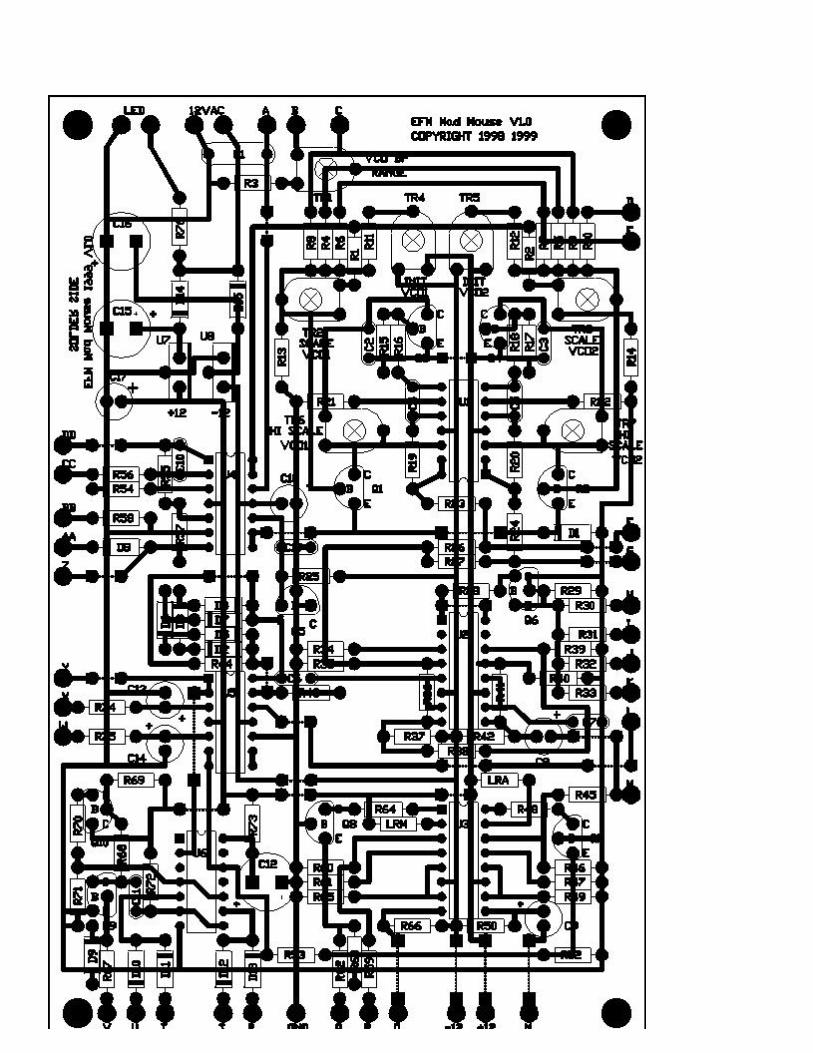
The pc board is a good quality board with silkscreen overlay and solder masking. No preparation is needed on the board. Use a magnifying glass tocheck your work as you go making sure there are no bridged solder pads.
Wire Jumpers
There are 25 wire jumpers. Install these in the spaces marked for jumpers after installing the resistors. As you install the resistors pile the cutoffs upsomewhere and use them as the jumper wires.
Resistors
1% Resistors
We want to build the VCOs as close to identical as possible. This is why we use 1% resistors. 5% resistors may be used for 1% resistors, match themwithin 1% with a digital ohm meter and install them as pairs one for vco1 and one for vco2. How well your VCOs track depends more on howclosely the following 1% resistor pairs are matched than anything else.
1% Resistors Part Needed
R4,R5 100K 1/4W 1% Resistor 2
R8,R9 150K 1/4W 1% Resistor 2
R13,R14 - R15,R17 1K 1/4W 1% Resistor 4
R16,R18 5K1 1/4W 1% Resistor 2
R19,R20 –R21,R22 1OK 1/4W 1% Resistor 4
R6,R7 2M2 1/4W 1% Resistor 2
5% Resistors Part Needed
R1,R2,R11,R12,R45 47K 1/4W 5% Resistor 5
R3,R34,R35,R39,R40R46,R47,R60,R61
220 1/4W 5% Resistor 9
R10 220K 1/4W 5% Resistor 1
R23,R24,R28,R30,R31R36,R37,R38,R41,R42R44,R48,R50,R53,R55R59,R62,R64,R66,R68
10K 1/4W 5% Resistor 20
R25 1M 1/4W 5% Resistor 1
R26,R27,R67,R72 100K 1/4W 5% Resistor 4
R29,R52,R63 2K2 1/4W 5% Resistor 3
R32 68K 1/4W 5% Resistor 1
R33 75K 1/4W 5% Resistor 1
R43,R76 4K7 1/4W 5% Resistor 2
R49,R57,R65 33K 1/4W 5% Resistor 3
R54,R56 390K 1/4W 5% Resistor 2
R58,R71 470 1/4W 5% Resistor 3
R69,R74,R75 1K 1/4W 5% Resistor 3
R70 3K3 1/4W 5% Resistor 1
R73 100 Ohm 1/4W 5% Resistor 1
RLA & RLM (Optional VCA/VCMod Linear resistors) 15K 1/4W 5% Resistor 2
NOTE: There is an error on the silkscreen C15 is labeled C17. See the overlay drawing for correct placement.
Capacitors Part Needed
C1 1.0UF Mylar Capacitor 1
C2,C3,C19 .01UF Polyester Capacitor 3
C11 .01UF Ceramic Capacitor 1
C4,C5 100PF Ceramic Capacitor 2
C6,C7 .002UF Polyester Capacitor 2
C8,C9,C13,C14 10UF/16V Electrolytic Capacitor 4
C10 .1UF Ceramic Capacitor 1
C12 100UF/16V Electrolytic Capacitor 1
C15,C16 470UF/35V Electrolytic Capacitor 2
C17,C18 1UF/16V Electrolytic Capacitor 2
Diodes Part Needed
D1-D13 1N914 or 1N4148 Signal Diode 13
D14,D15 1N4001 Power Diode 2
Trimmers Part Needed
TR1 100K PC Mount Trimmer 1
TR2,TR3,TR6,TR7 10K PC Mount Trimmer 4
TR4-TR5 50K PC Mount Trimmer 2
NOTE: There is an error on the silkscreen Q8 is labeled Q6. See the overlay drawing for correct placement.
Transistors Part Needed
Q1,Q2,Q5,Q9 2N3904 NPN Transistor 4
Q3,Q4,Q6,Q7,Q8,Q10 2N3906 PNP Transistor 6
ICs
Careful! When installing U1. It is the reverse of the other ICs.
ICs Part Needed
U1,U4,U5 TLO74 Quad OpAmp 3
U2,U3 LM13600 Dual OTA 2
U6 LM556 Dual Timer 1
U7 LM7812 +12V Voltage Regulator TO220 1
U8 LM7912 -12V Voltage Regulator TO220 1
This completes the assembly of the PCB.
Wiring
The following parts are mounted on the panel. They are connected to the PCB by "flying" connecting wires from the controls to the board.
Use the supplied punch layout by putting double sided tape on the back of the layout. What we want to do is line up the screw holes in the case lidwith the matching holes in the layout. Then press to stick it in place.
Use a punch to mark the holes for drilling, remove the layout and drill the holes.
Deburr the holes with a larger drill bit. Then apply the peel and press panel layout.
Mount the controls then tighten and put the knobs on.
Potentiometers Part Needed
P1,P9,P10,P12,P13 1M Panel Mount Pot 5
P2,P3,P5 50K Panel Mount Pot 3
P4,P8 100K Panel Mount Pot 2
P6,P7,P11 10K Panel Mount Pot 3
Switches Part Needed
S1-S4 SPDT Panel Mount Toggle Switch 4
Jacks Part Needed
J1 9 Pin Jack 1
J2 1/4" Phone Jack 1
J3 3.5MM Phone Jack 1
Mount the LED Panel Mount Red LED 1
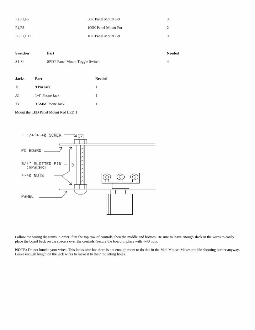
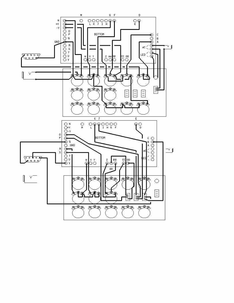
Follow the wiring diagrams in order; first the top row of controls, then the middle and bottom. Be sure to leave enough slack in the wires to easilyplace the board back on the spacers over the controls. Secure the board in place with 4-40 nuts.
NOTE: Do not bundle your wires. This looks nice but there is not enough room to do this in the Mad Mouse. Makes trouble shooting harder anyway.Leave enough length on the jack wires to make it to their mounting holes.

Smoke Test
Make sure the power switch is off and the transformer is unplugged. Plug in the mini power plug and plug the transformer into the wall.
If anything bad is going to happen now is the time. Be ready to turn the power switch off.
Look you’re work over well make sure all capacitors, transistors ics and diodes are placed properly.
Turn the unit on. The LED should light up. Nothing should smoke or be hot to the touch.
If there is a problem, turn it off and check your work over again.
The voltage is marked on the pcb next to the power regulator leads. Check for +12 and -12.
If the voltage isn't there, unplug ics until it returns be sure to turn the unit off before removing or plugging in anything. If you get +-12 back you havefound a bad ic. Replace it and try again.
If you still can't get +-12 the power rail(s) may be shorted. Find and remove the short.
Setup
To setup the MM you will need a way to send 1V per octave control voltages and gate. You will also need a reference keyboard.
Connect your controller to the MM and set the "Basic Patch" on the Mad Mouse.
Turn all trimmers to 50% on the Mad Mouse.
Connect the output jack to a monitor amp, turn the volume controls about half way up on the Mad Mouse and about 10% on the monitor amp. Turnthe VCF cutoff all the way up and turn the Mad Mouse on.
If you have done the heater mod the MM should warm up in about 60 seconds. If not wait about 10 minutes for the MM to stabilize.
Turn the VCO balance control to VCO1. Using a reference keyboard play a C2.
Match a C2 played on the MM to your reference by adjusting TR4. Play a C2 then C3 on the MM. Adjust TR2 until they are one octive apart. You

will have to adjust TR4 and TR2 several times to get it right. Then adjust the high scale trimmer TR6 by playing the C5-C6 octave.
All of these trimmers interact. You will have to play with them to correctly setup your oscillator. For your reference the settings on the test assemblyare TR2/TR3 about 4K, TR4/TR5 are very close to 50% and TR6/TR7 about 7.5K.
Once VCO1 is set up, adjust the VCO balance control to 50% and match VCO2 to VCO1. Get as close as you can.
After a burn in period, do this setup again.
Adjust the VCO pitch bend trimmer to allow a 1 note up-down range. This means play a C2 push the bender all the way up and adjust the trimmer sothat when the C2 key is played a D2 comes out, push the bender all the way down and it should play a B1 when pressing C2.
That should do it. The Mad Mouse should be ready to go.
If you want the VCA and VCMod to have linear response install a 15K resistor for LRA and LRM.
Start with the basic patch and test all control functions. I hope you enjoy your Mad Mouse.
Mad Mouse Addendum:
The Mad Mouse is a roller coaster I used to ride as a kid. You got in a blind cage and this thing jerked you around like a sack of potatoes. I loved it.Our electronic version has a lot in common with its namesake.
I really wanted the Mad Mouse to cost under $50. If you don't count the cost of the pc board I just made it. When selecting parts for the Mad Mouse Itried to get the best part for the price. For example the trimmers are ($0.26) low cost single turn. Multi -turn cermet trimmers would make the setupand tuning much easier and add stability to the synthesizer but cost ten times ($2.25) as much. My point is, I could have spent a lot of money puttingthis together but wanted it to be cheep enough for people to experiment with. The trade off is overall heat sensitivity. You will notice when you turnit on after being off for a while that the VCOs will be totally out of adjustment. If you wait about 10 minutes it will warm up and be fine. This isnormal for a non-compensated design. The filter is a resonate type and will self oscillate when the resonance is over 50% this is also normal.
If you decide to modify the parts list in favor of higher quality parts, try building it as specified first just to get it working and then modify away.
NOTE:
Use TLO74s only. Do not use TLO84s. They work but for some reason current consumption increases and the regulators run warm.
Heat, The Mad Mouse and Stability:
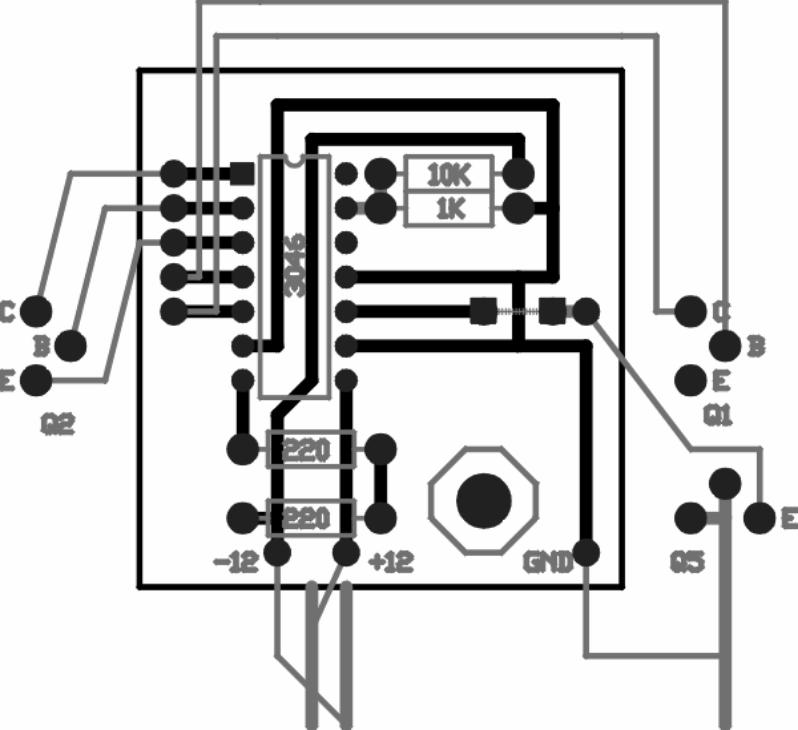
If the Mad Mouse is built in an enclosed case it is going to drift. It's probably going to drift a little even in open-air installations. The obvious solutionis tempco resistors. As soon as I can locate a good source I'll notify all MM owners. I will add a 3046 heater mod to the "Mad Mouse Mod Page"when I get it online but tempco's would be better for the Mouse.
If the heater mod or tempcos are used you can ignore this and install your MM almost anywhere in the case of your choice.
The Case:

I am disgusted! Radio Shack discontinued the case I built the prototype in. After years of this sort of abuse I should know better. There is a similarone available from national parts but it's not the same. The MM PCB grew a little while being manufactured and now it won't fit in the warehousecase! There is a project case #270-1807 available in the RS stores the board almost fits in. If you trim the leading edges a little and cutout a little witha round hobby tool bit it just fits in the box around the mounting post used to secure to top. The real bummer is the board really doesn’t fit the caseand overall it's bigger that the discontinued part. CRAP! I found an aluminum case like the ones MXR used to put their effects in but the cost is $22.The console case I built the Mini4 in is only $20. I'll keep looking….
The Hammond 1595EKB is available from Digikey #HM244-ND for $12.45. This is a sloping case that I think the MM would fit in with room to doa few mods. I have ordered one and will build one of the test assemblies in it when it comes in.
Silkscreen Errors:
I got rushed and just screwed it up.
Mouser Joins the Conspiracy:
Mouser has offered to keep a list of the parts for the Mad Mouse on file. By the time you receive this Kim Bates in the Mouser sales department willhave the list. So you can just call and ask for parts for the MM-1and she'll know what you are talking about. Pretty good for a company that can't gettheir computers to add. (It's a joke) I asked for a total one time and was told "sorry sir our computers don't add" I burst out laughing and said betweenfits "you probably think I'm crazy but trust me on this one, the only thing your computer actually does is add". I know she thought I was insane.

marjan's Mad Mouse Mod Page
I finally found time to make this mods. When I projected my mm deluxe I ended up with lots ofpots and switches for various modulation connecting and levels of modulations, so I thought ofmaking all possible ins and outs of mm, put jacks on them, make few (5) attenuators with jacksfor in and wiper out (voltage divider configuration), so I'd have 5 max modulation routing, plusfew multiples. Thats the idea, to keep mm small, and just to add "field" with jacks (like on ms20) and attenuators for modulation.
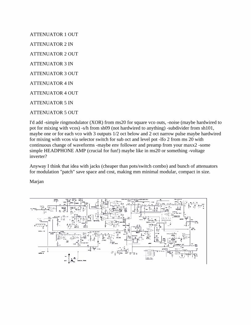
fig1: Added all ins and outs (jacks), include your mods for fine and coarse freq of each vco, andpw/pwm waveforms selectable (not shown), sync (simplified,you don't need that another res inseries with switch), lp/hp switch on vcf, eg1 mode to ADSR (without 4016),eg2 mode to haveswitchable on/off sustain and release (from multimoog) , lfo1 got level control on panel, manualtrig (like gnome), lfo1 range lo/normal speed, vcf switch for eg 1/2, vca sw for eg 1/2. Vco 1+2cv in controls both vcos. All jacks should be in close position (3.5mm mini jacks) for shorterconnections.Couple of multiples (3-4 shorted jacks). Maybe add heated vco version. NOTE: onyour schematic vcas for lfo and VCA are mixed pins (on pcb 13600 pin 5 is out for lfo vca notaudio VCA but schematic is other way around and so for all pins).
List of jacks:
CV IN
GLIDE CV OUT
VCO 1+2 CV IN
VCO 1 CV1 IN
VCO 1 CV2 IN
VCO 2 CV1 IN
VCO 2 CV2 IN
VCO 1 SAW OUT
VCO 2 SAW OUT
VCO 1 SQUARE OUT
VCO 2 SQUARE OUT
VCO 1 PWM IN
VCO 2 PWM IN
VCF AUDIO IN 1
VCF AUDIO IN 2
VCF OUT
VCF CV IN 1
VCF CV IN 2
VCA AUDIO IN
VCA CV IN
ENV 1 OUT
ENV 2 OUT
GATE IN
NOISE OUT
LFO 1 TRI OUT
LFO 1 SQR OUT
LFO 2 TRI OUT
LFO 2 SQR OUT
S/H IN
S/H CLK IN
S/H OUT
SUB IN
SUB 1 OCT OUT
SUB 2 OCT OUT
SUB 2 OCT PULSE OUT
RING MODULATOR OUT
MULTIPLE A 1-2-3
MULTIPLE B 1-2-3
ATTENUATOR 1 IN
ATTENUATOR 1 OUT
ATTENUATOR 2 IN
ATTENUATOR 2 OUT
ATTENUATOR 3 IN
ATTENUATOR 3 OUT
ATTENUATOR 4 IN
ATTENUATOR 4 OUT
ATTENUATOR 5 IN
ATTENUATOR 5 OUT
I'd add -simple ringmodulator (XOR) from ms20 for square vco outs, -noise (maybe hardwired topot for mixing with vcos) -s/h from sh09 (not hardwired to anything) -subdivider from sh101,maybe one or for each vco with 3 outputs 1/2 oct below and 2 oct narrow pulse maybe hardwiredfor mixing with vcos via selector switch for sub oct and level pot -lfo 2 from ms 20 withcontinuous change of waveforms -maybe env follower and preamp from your maxx2 -somesimple HEADPHONE AMP (crucial for fun!) maybe like in ms20 or something -voltageinverter?
Anyway I think that idea with jacks (cheaper than pots/switch combo) and bunch of attenuatorsfor modulation "patch" save space and cost, making mm minimal modular, compact in size.
Marjan

