efficient utility equipment: power distribution … · statcon (dstatcon) protects the distribution...
TRANSCRIPT
AL/EQ-TR-95-1005
EFFICIENT UTILITY EQUIPMENT: POWER DISTRIBUTION SYSTEMS AND POWER CONDITIONING EQUIPMENT
Robert Bernstein
Alfred University Alfred, NY 14802
Contract No. F08637-95-M-6014 May 1995
DISTRIBUTION A: Approved for public release; distribution unlimited.
ENVIRONICS DIRECTORATE ARMSTRONG LABORATORY
Air Force Materiel Command United States Air Force Tyndall Air Force Base, FL 32403-5323
DISCLAIMER
Reference herein to any specific commercial product, process, or service by trade name, trademark, manufacturer, or otherwise does not constitute or imply its endorsement, recommendation, or approval by the United States Air Force. The views and opinions of authors expressed herein do not necessarily state or reflect those of the United States Air Force. This report was prepared as an account of work sponsored by the United States Air Force. Neither the United States Air Force, nor any of its employees, makes any warranty, expressed or implied, or assumes any legal liability or responsibility for the accuracy, completeness, or usefulness of any information, apparatus, product, or usefulness of any information, apparatus, product, or process disclosed, or represents that its use would not infringe privately owned rights This document is submitted as an historical record of work performed. Limitations of the available media rendered editing impractical; therefore it is retained “as is.”
Standard Form 298 (Rev. 8/98)
REPORT DOCUMENTATION PAGE
Prescribed by ANSI Std. Z39.18
Form Approved OMB No. 0704-0188
The public reporting burden for this collection of information is estimated to average 1 hour per response, including the time for reviewing instructions, searching existing data sources, gathering and maintaining the data needed, and completing and reviewing the collection of information. Send comments regarding this burden estimate or any other aspect of this collection of information, including suggestions for reducing the burden, to Department of Defense, Washington Headquarters Services, Directorate for Information Operations and Reports (0704-0188), 1215 Jefferson Davis Highway, Suite 1204, Arlington, VA 22202-4302. Respondents should be aware that notwithstanding any other provision of law, no person shall be subject to any penalty for failing to comply with a collection of information if it does not display a currently valid OMB control number. PLEASE DO NOT RETURN YOUR FORM TO THE ABOVE ADDRESS. 1. REPORT DATE (DD-MM-YYYY) 2. REPORT TYPE 3. DATES COVERED (From - To)
4. TITLE AND SUBTITLE 5a. CONTRACT NUMBER
5b. GRANT NUMBER
5c. PROGRAM ELEMENT NUMBER
5d. PROJECT NUMBER
5e. TASK NUMBER
5f. WORK UNIT NUMBER
6. AUTHOR(S)
7. PERFORMING ORGANIZATION NAME(S) AND ADDRESS(ES) 8. PERFORMING ORGANIZATION REPORT NUMBER
9. SPONSORING/MONITORING AGENCY NAME(S) AND ADDRESS(ES) 10. SPONSOR/MONITOR'S ACRONYM(S)
11. SPONSOR/MONITOR'S REPORT NUMBER(S)
12. DISTRIBUTION/AVAILABILITY STATEMENT
13. SUPPLEMENTARY NOTES
14. ABSTRACT
15. SUBJECT TERMS
16. SECURITY CLASSIFICATION OF: a. REPORT b. ABSTRACT c. THIS PAGE
17. LIMITATION OF ABSTRACT
18. NUMBER OF PAGES
19a. NAME OF RESPONSIBLE PERSON
19b. TELEPHONE NUMBER (Include area code)
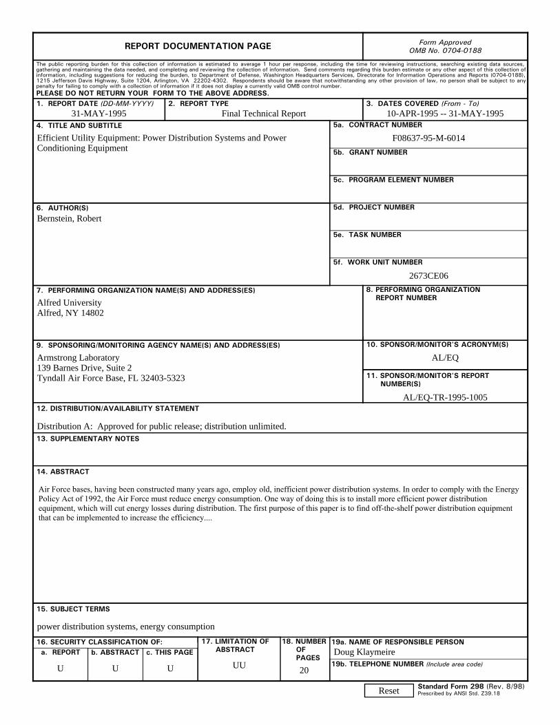
31-MAY-1995 Final Technical Report 10-APR-1995 -- 31-MAY-1995
Efficient Utility Equipment: Power Distribution Systems and Power Conditioning Equipment
F08637-95-M-6014
2673CE06
Bernstein, Robert
Alfred University Alfred, NY 14802
Armstrong Laboratory 139 Barnes Drive, Suite 2 Tyndall Air Force Base, FL 32403-5323
AL/EQ
AL/EQ-TR-1995-1005
Distribution A: Approved for public release; distribution unlimited.
Air Force bases, having been constructed many years ago, employ old, inefficient power distribution systems. In order to comply with the Energy Policy Act of 1992, the Air Force must reduce energy consumption. One way of doing this is to install more efficient power distribution equipment, which will cut energy losses during distribution. The first purpose of this paper is to find off-the-shelf power distribution equipment that can be implemented to increase the efficiency....
power distribution systems, energy consumption
U U U UU 20
Doug Klaymeire
Reset
)
... --Efficient Utility Equipment:
Power Distribution Systems and Power Conditioning Equipment
First Draft Report (May version)
Contract Number: F086379SM6014
Submitted to: Norma Myers 325 Contracting Squadron SOl Illinois Ave., SuiteS Air Force Contracting Tyndall AFB, FL 32404-5323
Written by: Mr. Robert Bernstein Alfred University Alfred, NY 14802
Management: Provost Ott
Report Period: 04/11/95-05/31/95
May 31, 1995
. . )
.. L INTRODUCTION
Air Force bases, having been constructed many years ago, employ old, inefficient power
distribution systems. In order to comply with the Energy Policy Act of 1992, the Air Force must
reduce energy consumption. One way of doing this is to install more efficient power distribution
equipment, which will cut energy losses during distribution. The first purpose of this paper is to
find off-the-shelf power distribution equipment that can implemented to increase the efficiency.
Air Force bases most likely do not have much in the way of power conditioning
equipment. In the past forty years, much equipment that is very sensitive to power disturbances
has been developed, including computers and sensitive industrial manufacturing equipment. The
present equipment on the Air Force bases probably cannot condition the power to these sensitive
loads effectively. This means that equipment can be interrupted or even damaged by the different
disturbances, so that business is interrupted and money is lost. These disturbances are also a
source of power loss, but can be protected against using certain equipment. The second scope of
this project is to find off-the-shelf power conditioning equipment which will protect sensitive
loads and increase efficiency.
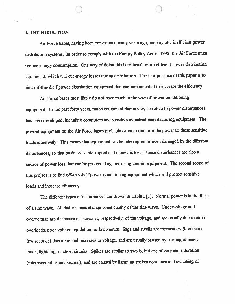
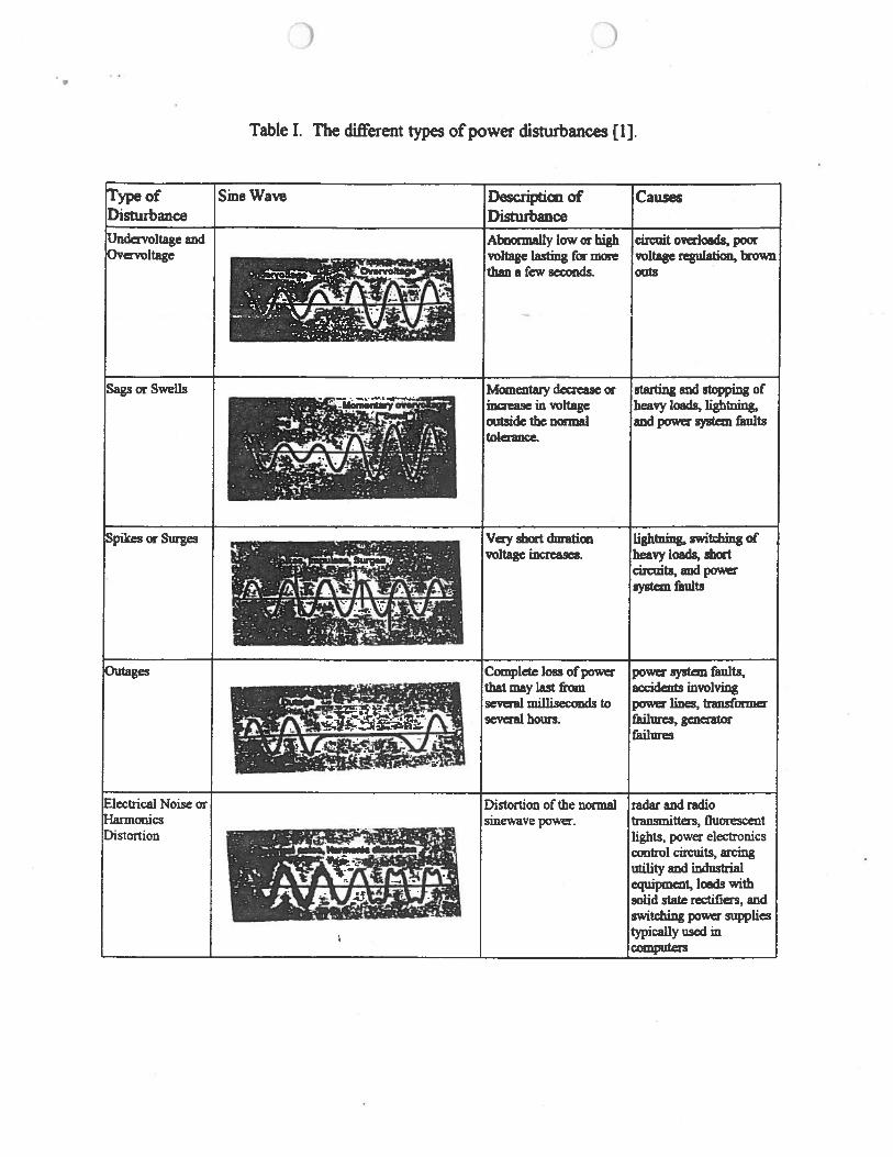
The different types of disturbances are shown in Table I [ 1]. Normal power is in the fonn
of a sine wave. All disturbances change some quality of the sine wave. Undervoltage and
overvoltage are decreases or increases, respectively, of the voltage, and are usually due to circuit
overloads, poor voltage regulation, or brownouts. Sags and swells are momentary (less than a
few seconds) decreases and increases in voltage, and are usually caused by starting of heavy
loads, lightning, or short circuits. Spikes are similar to swells, but are of very short duration
(microsecond to millisecond), and are caused by lightning strikes near lines and switching of
.. )
heavy loads. An outage is a complete loss of power and is caused by a fault in system,
transformer failure, power line disruption, or generator failure.
The last type of disruption is noise or harmonic distortion, which is a distortion in the
normal sine wave. This is caused by radio and radar, fluorescent lights, power electronics control
circuits, arcing utility and industrial equipment, and other standard appliances, such as computers,
copiers, and laser printers. Harmonic distortion is a major cause of efficiency loss because it
causes motor loads, pumps, and disk drives to overheat.
ll. WORK PERFORMED
Literature searches in the following areas were performed:
1. Current air base requirements with respect to connected load and power conditioning
required.
2. Power distribution and conditioning equipment available off-the-shelf for use to protect
equipment on the air base and increase efficiency.
Current Air Base Requirements:
The current base requirements were determined from the Energy Utilities Questionnaire
from 1992. Most air bases need a connected load of less than 80 MV A, but some, such as
Langley, need up to 195 MY A. The connected load that required conditioning is always less than
.8 MV A and the connected load that required an Uninterruptable Power Supply (UPS) is less than
.4MVA.
•
)
Power Distribution and Conditioning Equipment:
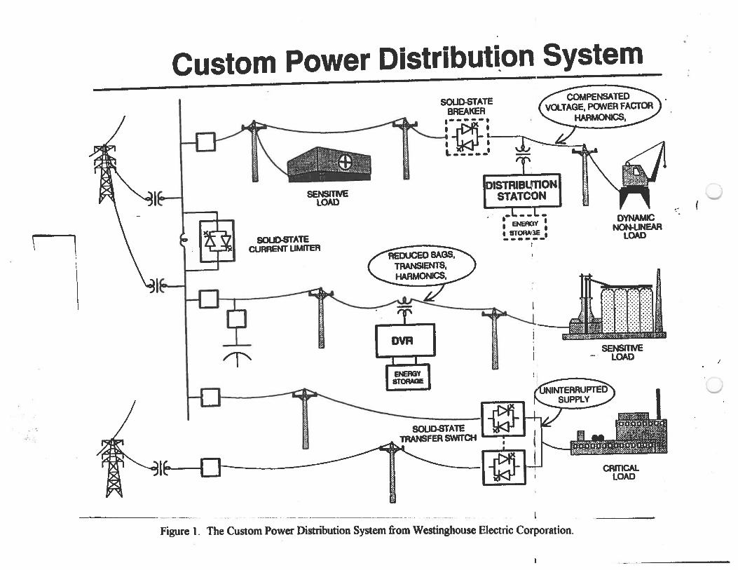
Because of the many different types of power disturbances, different power conditioning
products may need to be used together to minimize the disturbances. A set of custom power
products from Westinghouse Electric Corporation[2] can be used either separately or together to
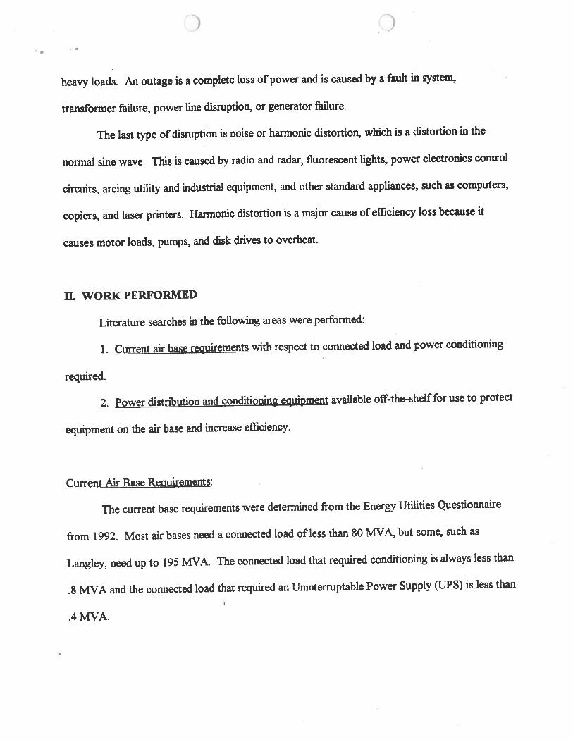
provide quality power. Figure 1 shows the Custom Power Distribution System. The Distribution
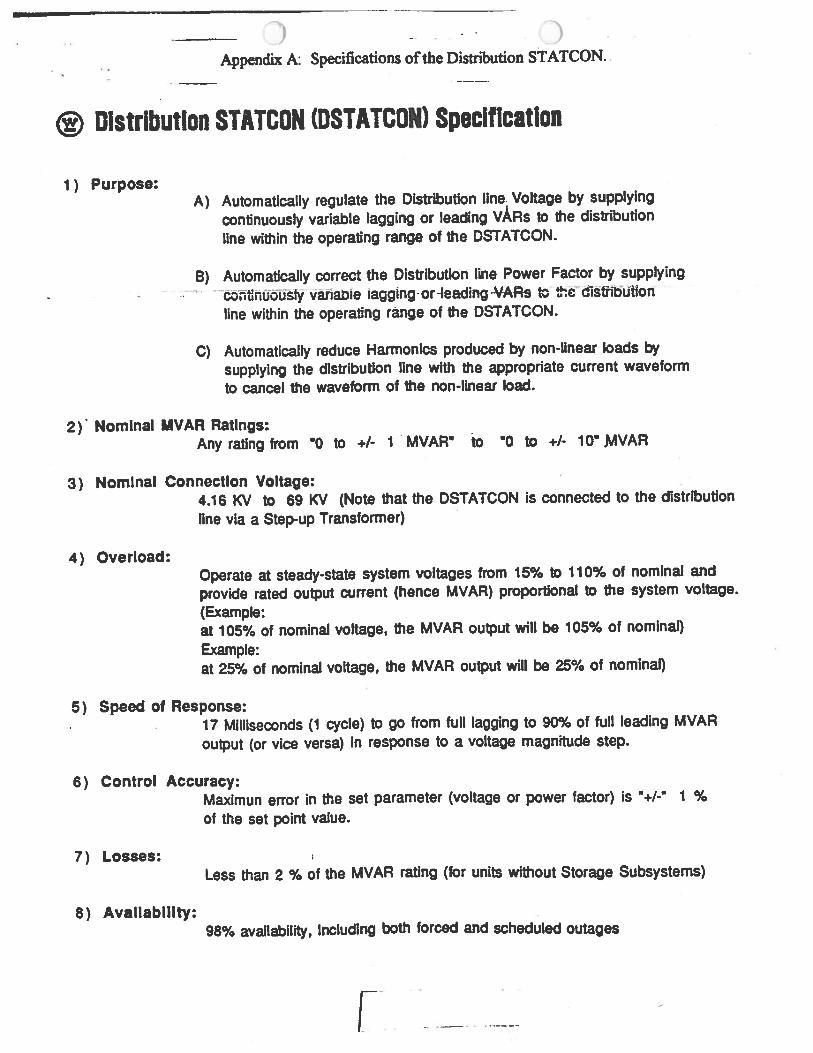
STATCON (DSTATCON) protects the distribution system from a fluctuating, nonlinear load.
The basic functions of the DSTATCON are reactive power compensation, voltage regulation, and
harmonic load current supply. With the addition of a Solid State Breaker and some type of
energy storage, the DSTATCON can also eliminate voltage sags, swells, transients, and power
intenuptions. The specifications of the DSTATCON are given in Appendix A
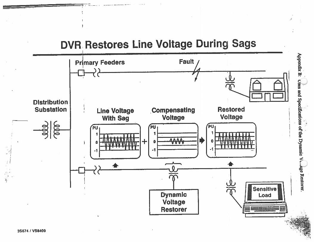
Also from Westinghouse, the Dynamic Voltage Restorer (DVR) protects the sensitive
load from disturbances that originate on the distribution or transmission system. The DVR can
reduce voltage sags, swells, and transients, provide voltage regulation, limit fault currents, and,
with the addition of shunt solid state breaker and some type of energy storage, prevention of
power intenuption. Appendix B shows two uses of the DVR as well as the specifications of the
DVR.
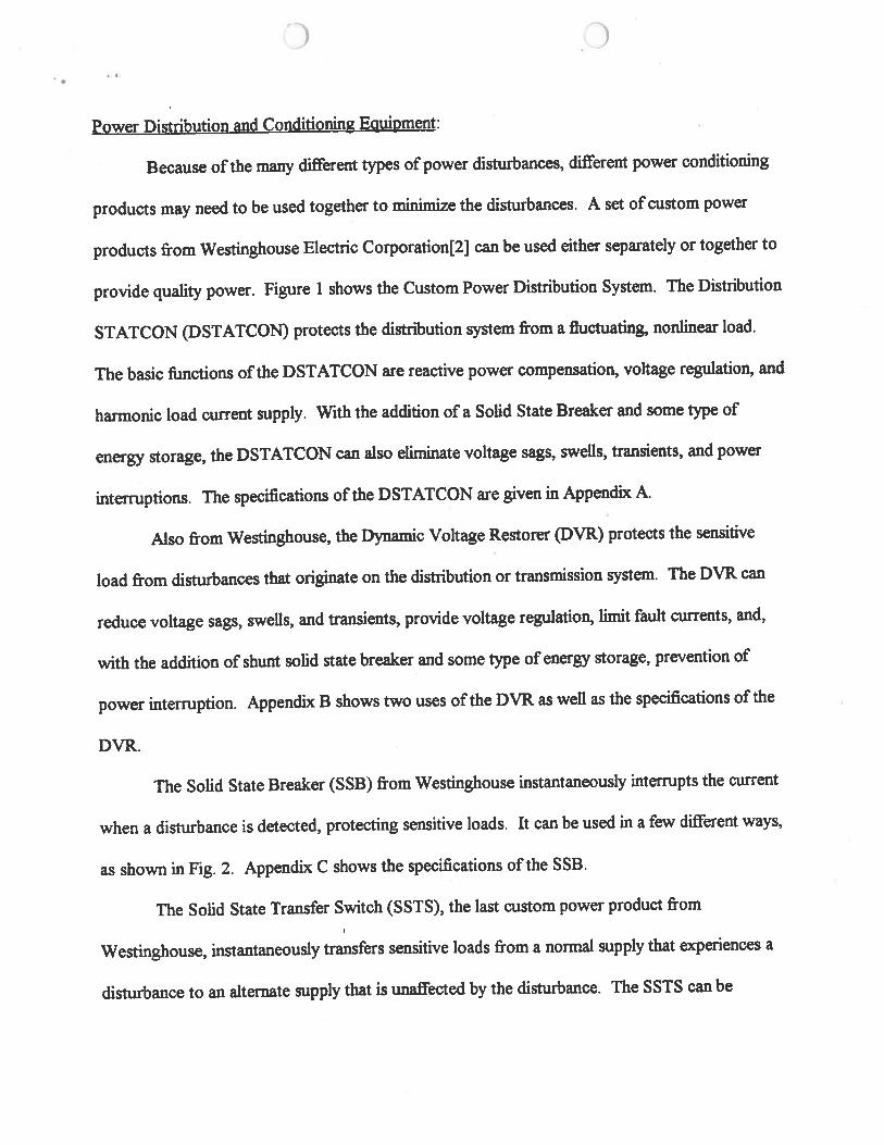
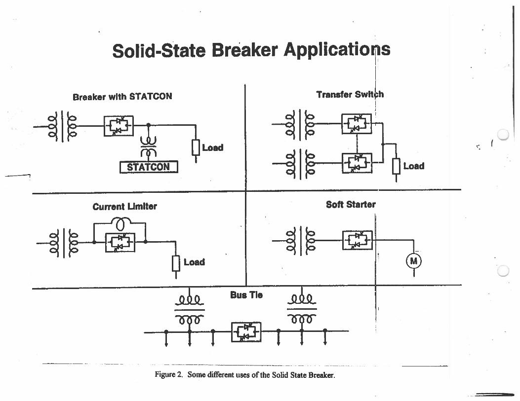
The Solid State Breaker (SSB) from Westinghouse instantaneously interrupts the current
when a disturbance is detected, protecting sensitive loads. It can be used in a few different ways,
as shown in Fig. 2. Appendix C shows the specifications of the SSB.
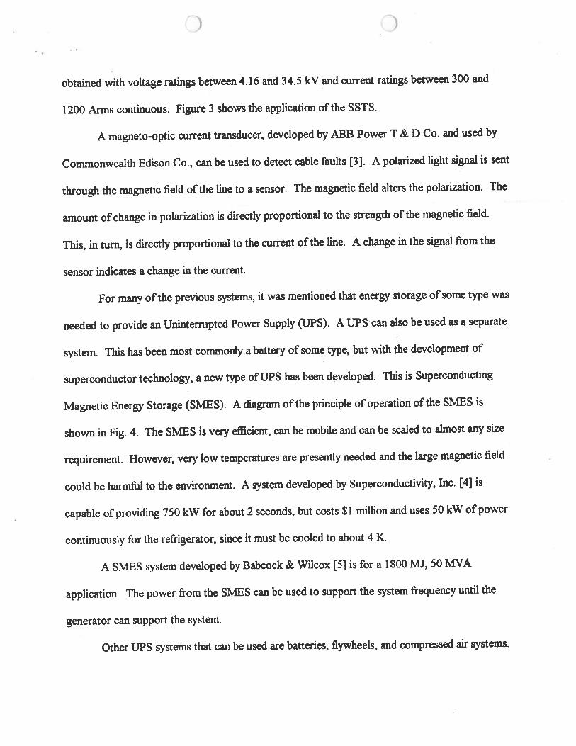
The Solid State Transfer Switch (SSTS), the last custom power product from
Westinghouse, instantaneously transfers sensitive loads from a normal supply that experiences a
disturbance to an alternate supply that is unaffected by the disturbance. The SSTS can be
)
obtained with voltage ratings between 4.16 and 34.5 kV and current ratings between 300 and
1200 Arms continuous. Figure 3 shows the application of the SSTS.
A magneto-optic current transducer, developed by ABB Power T & D Co. and used by
Commonwealth Edison Co., can be used to detect cable faults [3]. A polarized light signal is sent
through the magnetic field of the line to a sensor. The magnetic field alters the polarization. The
amount of change in polarization is directly proportional to the strength of the magnetic field.
This, in turn, is directly proportional to the current of the line. A change in the signal from the
sensor indicates a change in the current.
For many of the previous systems, it was mentioned that energy storage of some type was
needed to provide an Uninterrupted Power Supply (UPS). A UPS can also be used as a separate
system. This has been most commonly a battery of some type, but with the development of
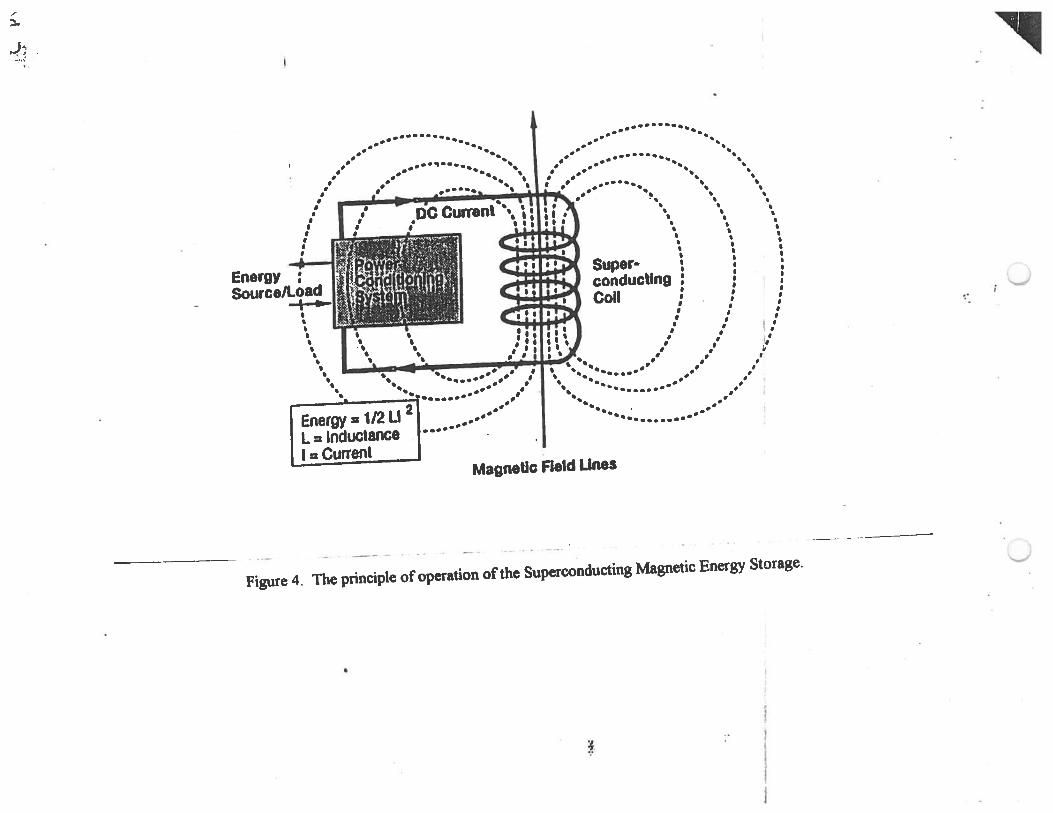
superconductor technology, a new type of UPS has been developed. This is Superconducting
Magnetic Energy Storage (S:MES). A diagram of the principle of operation of the SMES is
shown in Fig. 4. The SMES is very efficient, can be mobile and can be scaled to almost any size
requirement. However, very low temperatures are presently needed and the large magnetic field
could be harmful to the environment. A system developed by Superconductivity, Inc. [4] is
capable of providing 750 kW for about 2 seconds, but costs $1 million and uses 50 kW of power
continuously for the refrigerator, since it must be cooled to about 4 K.
A S:MES system developed by Babcock & Wilcox [5] is for a 1800 MJ, 50 MY A
application. The power from the SMES can be used to support the system frequency until the
generator can support the system.
Other UPS systems that can be used are batteries, flywheels, and compressed air systems.
) )
m PLAN FOR NEXT PERIOD
A continued literature search will be undertaken in the areas of power distribution and
conditioning equipment. More off-the-shelf equipment will be found and literature on these
systems will be studied.
)
REFERENCES
1. U.S. Department of Commerce, National Institute of Standards & Safety. "Power Quality."
NIST SP768A. Oct. 1990.
2. N.H. Woodley. "Solid State Custom Power Products for Distribution Feeder Power Quality
Improvement." Westinghouse Electric Corporation, March 2, 1995.
3. T.J. Meno and H.S. Gilleland. "138 kV Cable Fault Detection Using Magneto-Optic Current
Transducers and aNew Digital Differential Relay." Proceedings of the Anierican Power
Conference. Chicago, IL, 1995.
4. T.P. Sheahan. "Introduction to High Temperature Superconductors." Plenum Publishing
Corp.: 1994.
S. S.F. Kral, M. Aslam, P.F. Ribeiro, X. Huang, and M. Xu. "Superconducting Power Delivery
Systems for Transmission and Distribution Applications." Proceedings of the American
Power Conference, Chicago, IL, 1995.
•
Sags or Swells
Spikes or Surges
onics Distortion
Table I. The different types of power disturbances [1).
Sine Wave Desc.riptioo of Disturbance
Causes
Abnormally low or hiP circuit overloads, poor voltage 1astina for more voltage rqulation, brown than a few seconds. outs
Momentary deaeasc or iDaeasc in voltage outside the JlCJI1DIIl tolenmc:e.
Vtrj short doratioo voltage increases.
Complete loss of powathat may last from several mi1lisecoods to several hours.
Distortion of the normal sinewave power.
starting and stopping of heavy loads. lightning. and powa' systan faults
lighlnin& IWitciUDg of heavy loads, short circuits, and power system faults
powet systan faults, accidems involving powa- lines, transformer failures, generator failures
radar and radio transmitters, fluorescent lights, power electronics control cin:uits, arcing utility and industrial equipment, loads with solid state rectifiers, and switching power supplies typically used in c:ompo.ders
. ~· .
'l I
Custom Power Distribut~on System
/f'
--
SENSITIVE LOAD
SOLD-STATE CURRENT UMfTEA
OVA
SOLJO.STATE BREAKER
!~': ... ----... ....... L---·-'
. ------• ENEAOY : t ITORA•le e ------1
·-· ·-- ·-----· ··---- ·----------·-··-··· .. -··--· -·. I
Figure 1. The Custom Power Distribution System from Westinghouse Electric Corporation.
DYNAMIC NON-UNEAR
LOAD
SENSITIVE LOAD
CRr11CAl LOAD
..
I
v
-----,
~
. .
Solid-State Breaker Applicatio~s
Breaker with STATCON
Load -rf' 1-STATCON l
Current Limiter
~ ~
I
Transfer Swlt~h i I J
i .. a a I
Soft Starter
~~jg • IWI • I ~ Load
Bus Tie
(Sr(f 1)rf I .:. I 1¢1 I I
------- -- - -·-- -· -------·-- . -- .. - - ---------· --· ·
Figure 2. Some different uses of the Solid State Breaker.
~-
Load
......._,;

Solid-state distribution transfer switch
SOURCE1 11 I
I ,Y., 0111 (2 ~ SSB1 p
I jl\
CONTROL
.. ·
~·· I '·: i
'r"'·~· .... •
~i... J ••
SOURCE2 12 . \1 '
£5! ~ I
p SSB2 LOAD
-~··.~ v
··-- - ----------- ----------Figure 3. Some applications of the Solid State Transfer Switch.
/
:l.
--!?
··•········••· ···········•·• .. .. .. .. . •• • •••• •••• •• •
. ·· ······~~······ ··. ..· ············· ...... . · .. · ..... '• .· .. ·· ··. •,
•' , •, . . .. ········· ... •, .. .. ·~. ·. .. . . ' ' . ' . '
, ' . .
, . .
, .~ ..... ~~·i'(!77'~~t~·' • ' ~
f ,t;~; • ·,t i ,_"'•, I ft.~ I • 0
• • • ~ ~ I
Super· 1 1 :
I I t
conducalng : : :
Coli i i : • f •
• •
• • • f ' 1 f I I : . , .
' f ' f
' . ~· •• •• • ,'I', ... ·········· .. · ,• .· ·. .... ..• ,•
2 --· . ••• ••••••••• •• • ;
Energy = 112 U .. --.. - ··.... ...·· .. .. .. :
L = Inductance I.····· · · · · · · · · · · I= Current
MagneUc Field Unes
---· - ·------
Figure 4. The principle of operation of the Superconducting Magnetic Energy Storage. \_,1
~· l
I j
Appendix A:. Specifications of the Distribution STATCON ..
@ Distribution STATCON (DSTATCON) Specification
1) Purpose: A) Automatically regulate the Distribution line. Voltage by supplying
continuously variable lagging or leading vARs to the distribution
line within the operating range of the DSTATCON.
B) Automatically correct the Distribution line Power Factor by supplying
-· ~ · ---continUously variable lagging-or -feeding -\lARs tcnhEf dlstnculion
line within the operating range of the OSTATCON.
C) Automatically reduce Harmonics produced by non-linear loads by
supplying the distribution line with the appropriate current waveform
to cancel the waveform of the non-linear load.
2) · Nominal MVAR Ratings: Any rating from •o to +I· 1 . MVAR• to •o to +1- 10• MVAR
3) Nominal Connection Voltage:
4) Overload:
4.16 KV to 69 KV (Note that the DSTATCON is connected to the distribution
nne via a Step-up Transformer)
Operate at steady-state system voltages from 15% to 11 0% of nominal and
provide rated output current (hence MVAR) proportional to the system voltage.
(Example: at 105% of nominal voltage, the MVAR output will be 105% of nominal)
Example: at 25% of nominal voltage, the MVAR output will be 25% of nominal)
5) Speed of Response: 17 Milliseconds (1 cycle) to go from full lagging to 90% of full leading MVAR
output (or vice versa) in response to a voltage magnitude step.
6) Control Accuracy:
7) Losses:
8) Availability:
Maximun error in the set parameter (voltage or power factor) is •+/-· 1 o/o
of the set point value.
Less than 2 %of the MVAR rating (for units without Storage Subsystems)
98% availability, Including both forced and scheduled outages

(i) Distribution STATCON (DSTATCON) Spec. (Continued)
9) Harmonics: The harmonic current produced by the DST ATCON as a Percentage of the rated
maximum continuous current of the OSTA1CON will not exceed the following:
1.0o/o for any odd Harmonics
0.5% for any even Harmonics
1 .5% for the RMS total of all Harmonics
In addition the CST AT CON is designed to ~oid resoriaiice with any other
distribution system device, such as: capacitor banks, filters, etc.
1 0) Negative Sequence System Voltages:
The DSTATCON is designed to operate with a Steady State Maximum Negative
Sequence System Voltage of 4.0%
11 ) Redundancy and Maintainability:
A) 1 0% redundancy in the individual Power Electronic devices in each Phase
B) 25% redundancy of the cooling system fans (or blowers)
C) Replacement of individual Power Electronic devices requires no more
than 2 Hours.
-

I I
I
••• •
. · (; . i'· :- . . -..
@ Distribution STA TCON (DSTATCON) Specification (with Energy Storage Subsystem)
The Distribution STATCON with Energy Storage is the same as the
Specification without Energy Storage except for the following additions:
1) Purpose:
I
A) With the addition of an Energy Storage Subsystem and a Solid-State Bkr.,
automaticaUy Supply or Absorb continuously variable Real Power to the
distribution line to eliminate Voltr:!~! S~~. Swells 8.!'1d Tr~.nsients
within the capabilities of the Storage Subsystem.
B) With the addition of an Energy Storage Subsystem and a Solid-State Bkr.,
automatically prevent power interruptions by supplying the appropriate
amount of continuously variable Real Power to the distribution line
during the Interruption period within the capabilities of the Storage
Subsystem.
2) Typical Storage Subsystems Sizes: 1 to 100 Megajoules (or 1 to 100 Megawattseconds) (or 0.3 to 30 Kilowatt-hour)
L_ --------
.·.~:I I
.: I
·;.,
!!!!!!!!!!!!!!!!!!!!!!!!!=========\;. . -··· -- .. . ---- .. --- ·- ....
DVR, Restores Line Voltage During Sags I
Distribution Substation
~~~ I
3S674 I VS8409
Pr~mary Feeders Faui'L
~~~--------------~7~
Line Voltage With Sag
PU 1 I I I I I I I
.:1 'YfM'~YYJrl+
. Compensating Voltage
PU 1
0 A A. A.A. ¥¥¥!_
·1 .J
• PU
ReE~tored
Voltage
1 ..............
0 1-&+Hof+
·1 ~~...~...~......_._.
& • ~~ ... ,--A--..
CJ
T l ' ~ Sensitive
Dynamic Voltage Restorer
'\ Load
De aU
,f
~
l ~c ~~
8.
t -B.
. g . . fjil ••
a, ~ -
f
f. 0
< (' • .; c
l ~

DVR: Compensates Switching Transients
Distribution Substation •
.
~~~
Primary Feeders
~~------------------------------·~---
. Switching Transient
fPU 1 I ) I I+
' s r 01 f~~ 'f I -1
PU 1 I
0 Ill. Ill"
-1 1
I •
.)
I '( • ~ • - l I
S,tltched Capacitor
Dynamic Voltage Restorer
. . 4·" .. ~~
•. ~ -~ . ". ~~-,;'!i,lM"'r. . • ..- ,.-, I
' •. ' . :l, ·i: 1: ,J o~_ \). r.===:;-il' ' .. 1 ; ~. ,_ . : + ::
Load
)
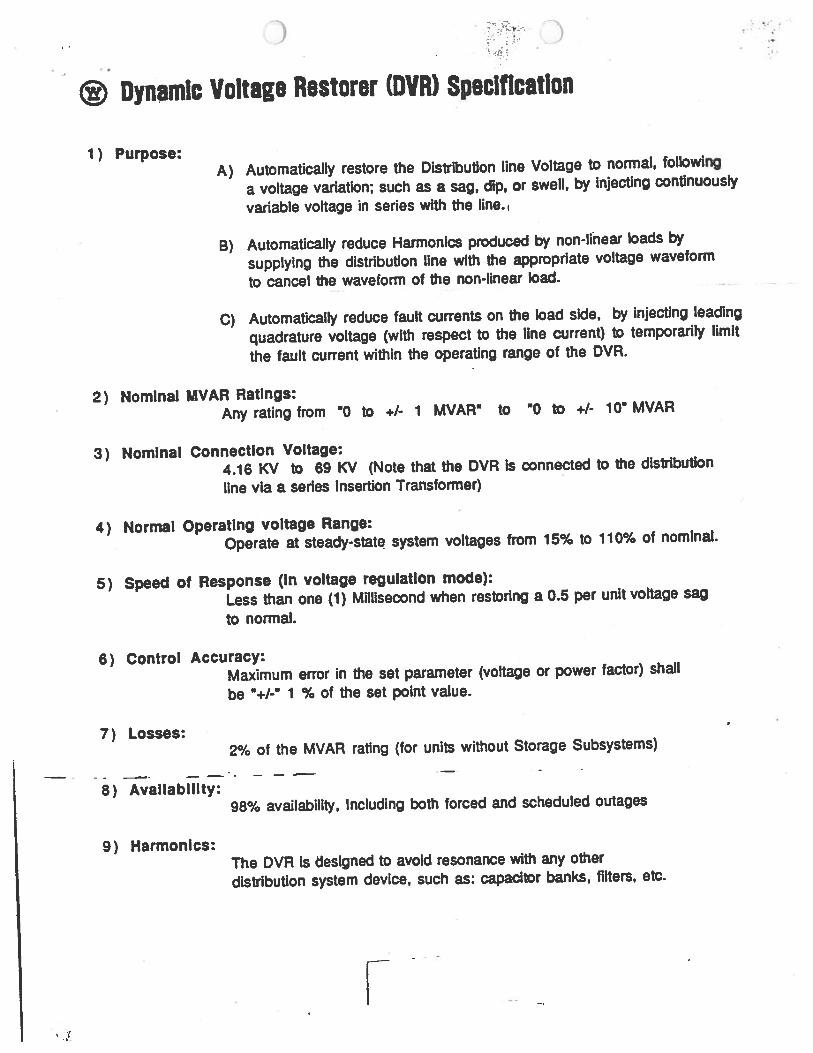
® Dynamic Voltage Restorer (DVIU Spaclflcatlon
1) Purpose: A) Automatically restore the Distribution line Voltage to normal, following
a voltage variation; such as a sag, dip, or swell, by Injecting continuously
variable voltage in series with the line.,
B) Automatically reduce Harmonics produced by non-linear loads by
supplying the distribution line with the appropriate voltage waveform
to cancel the waveform of the non-linear load.
C) Automatically reduce fault currents on the load side, by Injecting leading
quadrature voltage (with respect to the line current) to temporarily limit
the fault current within the operating range of the DVR.
2) Nominal MVAR Ratings: Any rating from ·o to +1- 1 MVAR• to ·o to +1- 10• MVAR
3) Nominal Connection Voltage: 4.16 KV to 69 KV (Note that the DVR Is connected to the distribution
line via a series Insertion Transformer)
4) Normal Operating voltage Range:
Operate at steady-stat~ system voltages from 15% to 11 0% of nominal.
5) Speed of Response (In voltage regulation mode):
Less than one (1) MDiisecond when restoring a 0.5 per unit voltage sag
to normal.
6) Control Accuracy:
7) Losses:
8) Availability:
9) Harmonics:
Maximum error in the set parameter (voltage or power factor) shall
be ••1-· 1 % of the set point value.
2% of the MVAR rating (for units without Storage Subsystems)
98% availability, Including both forced and scheduled outages
The DVR is designed to avoid resonance with any other
distribution system device, such as: capacitor banks, filters, etc.
' ..
~ .. . :~
) ; . ~- )
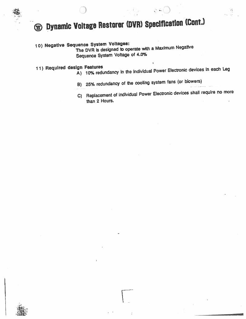
@ ~ynamlc Voltage Restorer (DVR) Spaclftcatlon (CantJ
1 o) Negative Sequence System Voltages:
The DVR Is designed to operate with a Maximum Negative
Sequence System Voltage of 4.0%
11) Required design Features A) 10% redundancy In the individual Power Electronic devices In each Leg
B) 25% redundancy of the cooling system fans (or blowers)
C) Replacement of individual Power Electronic devices shall require no more
than 2 Hours.
) ' ·
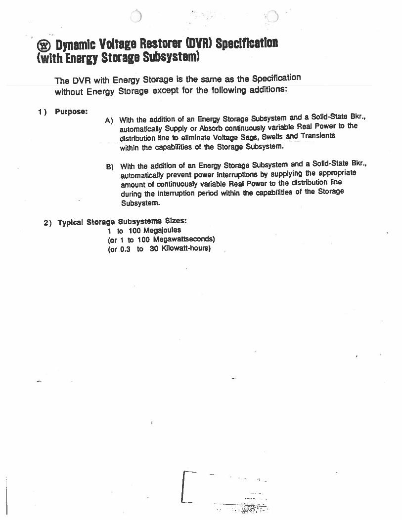
@ Dynamic Voltage Restorer (DVR) Specification (with Energy Storage Subsystem)
The DVR with Energy Storage is the same as the Specification
without Energy Storage except for the following additions:
1) Purpose: A) With the adcfrtion of an Energy Storage Subsystem and a Solid-State Bkr .,
automatically Supply or Absorb continuously variable Real Power to the
distribution line 1D eliminate Voltage Sags, Swells and Transients
within the capabDities of the Storage Subsystem. --
B) With the addition of an Energy Storage Subsystem and a Solid-State Bkr.,
automatically prevent power Interruptions by supplying the appropriate
amount of continuously variable Real Power to the distribution line
during the interruption period within the capabilities of the Storage
Subsystem.
2) Typical Storage Subsystems Sizes: 1 to 1 00 Megajoules (or 1 to 100 Megawattseconds) (or 0.3 to 30 Kilowatt-hours)
[
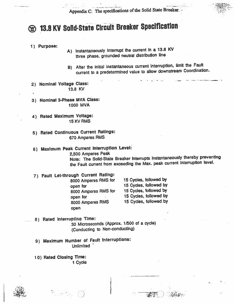
- - - .. · : .· .. Appendix C: The specifications of the Solid State Breaker. ~
® ~3.8 KV SoDd·Stata Circuit Breaker Speclftcatlon ·
1) Purpose: A) Instantaneously Interrupt the current In a 13.8 KV
three phase, grounded neutral distribu,on line
B) After the initial instantaneous current Interruption, Omit the Fault
current to a predetermined value to allow downstream Coordination.
2) Nominal Voltage Class: 13.8 KV
3) Nominal 3-Phase MVA Class: 1000 MVA
4) Rated Maximum Voltage: 15KVRMS
5) Rated Continuous Current Ratings:
670 Amperes RMS
6) Maximum Peak Current Interruption Level:"
2,500 Amperes Peak
· - · - ~ - ---·=--- -
Note: The Solid-State Breaker Interrupts Instantaneously thereby preventing
the Fault current from exceeding the Max. peak current Interruption level.
7) Fault Let-through Current Rating:
8000 Amperes RMS for
open for 8000 Amperes RMS for open for 8000 Amperes RMS open
_ 8~) Rated lnterruptln~ Time:
15 Cycles, followed by 15 Cycles, followed by 15 Cycles, followed by 15 Cycles, followed by 15 Cycles, followed by
30 Microseconds (Approx. 11500 of a cycle)
(Conducting to Non-conducting)
9) Maximum Number of Fault Interruptions:
Unlimited 1
1 0) Rated Closing nrne: 1 Cycle
)