efficient over-the-air remote reprogramming of wireless sensor
TRANSCRIPT
Efficient Over-the-air Remote Reprogramming
of Wireless Sensor Networks
by
Nasif Bin Shafi
A thesis submitted to the
School of Computing
in conformity with the requirements for
the degree of Master of Science
Queen’s University
Kingston, Ontario, Canada
November 2011
Copyright c© Nasif Bin Shafi, 2011

Abstract
Over-the-air reprogramming is an important aspect of managing large wireless sensor
networks. However, reprogramming deployed sensor networks poses significant chal-
lenges due to the energy, processing power and memory limitation of sensor nodes.
For improved energy efficiency, a reprogramming mechanism should use less trans-
mission and flash writing overhead. Past research has proposed different mechanisms
for reprogramming deployed sensor networks. However, all of these mechanisms pro-
duce large patches if software modifications involve changing program layouts and
shifting global variables. In addition, existing mechanisms use large amounts of ex-
ternal flash and rewrite entire internal flash. In this thesis, we present a differential
reprogramming mechanism called QDiff that mitigates the effects of program layout
modifications and retains maximum similarity between old and new software using a
clone detection mechanism. Moreover, QDiff organizes the global variables in a novel
way that eliminates the effect of variable shifting. Our experiments show that QDiff
requires near-zero external flash, and significantly lower internal flash rewriting and
transmission overhead than leading existing differential reprogramming mechanisms.
i

Acknowledgments
First and foremost, I offer my sincerest gratitude to my supervisor, Dr. Hossam Has-
senein, who has supported me throughout my thesis with his patience and knowledge,
whilst allowing me the room to work in my own way. He has been my inspiration as
I hurdle all the obstacles in the completion this research work. His in-depth knowl-
edge and keen interest in this eld, his logical way of thinking, prudent guidance and
suggestions at all stages of the work have been very helpful to complete this thesis.
Throughout my research work, I has been blessed with a great colleague Dr. Kashif
Ali, who introduced the field of wireless sensor networks, and taught how to carry on
a research work. His extraordinary patience in reading numerous inferior drafts and
for making them publishable is really appreciable. Both the syntactical and technical
aspects of the text have been improved through his careful reading of the manuscript.
I am deeply grateful to him for his patience, keen judgement, valuable advice and
cooperation to successfully complete this thesis.
I would like to acknowledge with sincere thanks the all-out cooperation and ser-
vices rendered by Basia Palmer and other members of TRL lab for many things.
ii

I would like to thank my wife, Safia Hasan and my parents for their constant support,
patience and inspiration.
Above all, I would like to thank the omnipresent Allah, for answering my prayers
for giving me the strength to finish this thesis successfully.
iii

List of Acronyms
(C)ELF (Compact) Executable and Linkable FormatEEPROM Electrically Erasable Programmable Read Only MemoryiHEX Intel Hexadecimal formatIoT Internet of ThingsJVM Java Virtual MachineLCS Longest Common Sub-sequenceLED Light-emitting DiodeLiteOS Lite Operating SystemLSB Least Significant BitMSB Most Significant BitnesC networked embedded systems COS Operating SystemRAM Random Access MemoryRISC Reduced Instruction Set ComputingROM Read-only MemorySOS Sensor Operating SystemSPI Serial Peripheral InterfaceSymtab Symbol tableTinyOS Tiny Operating SystemWSN Wireless Sensor Networks
iv
Contents
Abstract i
Acknowledgments ii
List of Acronyms iv
Contents v
List of Tables vii
List of Figures viii
Chapter 1: Introduction 11.1 Motivation . . . . . . . . . . . . . . . . . . . . . . . . . . . . . . . . . 31.2 Thesis Contribution . . . . . . . . . . . . . . . . . . . . . . . . . . . . 51.3 Organization . . . . . . . . . . . . . . . . . . . . . . . . . . . . . . . 6
Chapter 2: Background and Literature Survey 72.1 Background . . . . . . . . . . . . . . . . . . . . . . . . . . . . . . . . 72.2 Literature Survey . . . . . . . . . . . . . . . . . . . . . . . . . . . . . 14
2.2.1 Dissemination Protocols . . . . . . . . . . . . . . . . . . . . . 142.2.2 System Level Reprogramming . . . . . . . . . . . . . . . . . . 162.2.3 Virtual Machine Based Reprogramming . . . . . . . . . . . . . 162.2.4 Modular Reprogramming . . . . . . . . . . . . . . . . . . . . . 172.2.5 Differential Reprogramming . . . . . . . . . . . . . . . . . . . 19
Chapter 3: QDiff: A Differential Reprogramming Scheme 223.1 Introduction . . . . . . . . . . . . . . . . . . . . . . . . . . . . . . . . 223.2 Motivation, Problem and Objective . . . . . . . . . . . . . . . . . . . 233.3 QDiff: Differential-based Reprogramming Scheme Using Clone Detection 263.4 QDiff Patch Creation Process . . . . . . . . . . . . . . . . . . . . . . 30
3.4.1 Branches . . . . . . . . . . . . . . . . . . . . . . . . . . . . . . 31
v

3.4.2 Global Variables . . . . . . . . . . . . . . . . . . . . . . . . . 383.4.3 Indirect Addressing . . . . . . . . . . . . . . . . . . . . . . . . 453.4.4 Relative Jumps . . . . . . . . . . . . . . . . . . . . . . . . . . 52
3.5 QDiff Patch Deployment Process . . . . . . . . . . . . . . . . . . . . 53
Chapter 4: Implementation and Evaluation 574.1 Implementation details . . . . . . . . . . . . . . . . . . . . . . . . . . 574.2 Evaluation Scenarios . . . . . . . . . . . . . . . . . . . . . . . . . . . 594.3 Quantitative Performance Metrics . . . . . . . . . . . . . . . . . . . . 714.4 Performance Evaluation . . . . . . . . . . . . . . . . . . . . . . . . . 72
4.4.1 Patch size . . . . . . . . . . . . . . . . . . . . . . . . . . . . . 724.4.2 Internal flash writing . . . . . . . . . . . . . . . . . . . . . . . 734.4.3 External flash usage . . . . . . . . . . . . . . . . . . . . . . . 754.4.4 System Restart . . . . . . . . . . . . . . . . . . . . . . . . . . 754.4.5 Code Overheads . . . . . . . . . . . . . . . . . . . . . . . . . . 774.4.6 Heterogeneity . . . . . . . . . . . . . . . . . . . . . . . . . . . 78
Chapter 5: Conclusion 79
Bibliography 81
vi

List of Tables
4.1 Internal flash memory bytes comparison for the Stream, Hermes and
QDiff . . . . . . . . . . . . . . . . . . . . . . . . . . . . . . . . . . . . 75
4.2 External flash memory bytes comparison for the Stream, Hermes and
QDiff . . . . . . . . . . . . . . . . . . . . . . . . . . . . . . . . . . . . 76
4.3 Qualitative comparison of various reprogramming schemes . . . . . . 78
vii

List of Figures
1.1 Generic architecture of WSNs mote. . . . . . . . . . . . . . . . . . . . 2
1.2 Software architecture of sensor mote(modified from [56]). . . . . . . . 3
2.1 Operating system architecture for wireless sensor networks. . . . . . . 8
2.2 Virtual machine with other layers. . . . . . . . . . . . . . . . . . . . . 10
2.3 Layout of an Executable and Linkable Format (ELF) file . . . . . . . 13
2.4 Classification of over-the-air reprogramming in WSNs. . . . . . . . . . 15
3.1 Important steps of a differential-based reprogramming scheme. . . . . 27
3.2 Major steps of the QDiff differential reprogramming scheme. . . . . . 28
3.3 Example of function call address change due to code insertion. . . . . 32
3.4 Example of address change due to function reordering. . . . . . . . . 32
3.5 Padding newly added code block at the end of program code. . . . . . 33
3.6 An illustration of QDiff scheme, handling simultaneous function inser-
tion and deletion. . . . . . . . . . . . . . . . . . . . . . . . . . . . . . 35
3.7 Flowchart for fixing branches . . . . . . . . . . . . . . . . . . . . . . 36
3.8 An exemplary scenario showing addition of multiple functions. . . . . 37
3.9 Illustration of QDiff handling multiple functions. . . . . . . . . . . . . 38
3.10 Comparison of bss section for traditional and QDiff ELF file. . . . . . 39
3.11 Illustration of traditional ELF and QDiff modified data/bss sections. 41
viii

3.12 Illustration of global variable addition, both initialized and uninitialized. 42
3.13 Sequence of variables including array after addition in bss section of
GCC compiled ELF file. . . . . . . . . . . . . . . . . . . . . . . . . . 44
3.14 Sequence of variables including array in bss section of QDiff modified
ELF file. . . . . . . . . . . . . . . . . . . . . . . . . . . . . . . . . . . 45
3.15 Flowchart for fixing global variables. . . . . . . . . . . . . . . . . . . 46
3.16 Illustration of indirect address access and global variables, for tradi-
tional and modified ELF files. . . . . . . . . . . . . . . . . . . . . . . 48
3.17 Illustration of indirect address access and global arrays, for traditional
and modified ELF files. . . . . . . . . . . . . . . . . . . . . . . . . . . 49
3.18 Flowchart for fixing indirect addresses. . . . . . . . . . . . . . . . . . 51
3.19 Illustration of change in the relative jump instructions. . . . . . . . . 53
3.20 Illustration of QDiff changes to handle relative jumps. . . . . . . . . . 54
3.21 Flowchart for fixing relative jumps. . . . . . . . . . . . . . . . . . . . 55
3.22 Flowchart for QDiff. . . . . . . . . . . . . . . . . . . . . . . . . . . . 56
4.1 An IRIS sensor mote(LEDs are shown in circle) . . . . . . . . . . . . 60
4.2 Case 1: Timer value is changed. . . . . . . . . . . . . . . . . . . . . 63
4.3 Case 2: Addition of one toggle in Timer0. . . . . . . . . . . . . . . . 64
4.4 Case 3: Addition of one toggle in each timer i.e. Timer0 toggles LED0
and LED1, Timer1 toggles LED1 and LED2 , Timer2 toggles LED2
and LED0. . . . . . . . . . . . . . . . . . . . . . . . . . . . . . . . . 65
4.5 Case 4: Toggles are reorganized i.e. Timer0 toggles LED2 and LED0,
Timer1 toggles LED2 and LED1 , Timer2 toggles LED1 and LED0. . 66
ix

4.6 Case 5: RadioCountToLeds is modified to display last two bits on its
LEDs and value displayed in third LED is discarded. . . . . . . . . . 67
4.7 Case 6: RadioCountToLeds is modified to displays 1’s complement of
least significant three bits of received counter. . . . . . . . . . . . . . 68
4.8 Case 7: RadioCountToLeds is modified to display most significant
three bits of received counter value. . . . . . . . . . . . . . . . . . . . 69
4.9 Case 8: RadioCountToLeds is modified to displays counters bits if it
has an even value, otherwise no change is made in sensor mote LEDs. 70
4.10 Patch size comparison for the Stream, Hermes and QDiff reprogram-
ming schemes. . . . . . . . . . . . . . . . . . . . . . . . . . . . . . . . 73
4.11 Internal flash writing comparison for the Stream, Hermes and QDiff
reprogramming schemes. . . . . . . . . . . . . . . . . . . . . . . . . . 74
4.12 External flash memory pages comparison for the Stream, Hermes and
QDiff reprogramming schemes. . . . . . . . . . . . . . . . . . . . . . . 76
x
1
Chapter 1
Introduction
Wireless Sensor Networks (WSNs) is attracting great deal of attention from both
academic and industrial researchers. A typical network is composed of a large number
of small-sized, battery-powered or energy harvesting wireless sensor nodes that are
limited in available power, processing, and communication capability. Wireless sensor
networks have a broad range of applications that include battlefield surveillance [4,24],
industrial process monitoring and control [43, 68], Habitat monitoring [44], Volcano
Monitoring [64], wildlife monitoring [31], structure monitoring [33, 66], Health care
monitoring [8, 30, 36], underground mining [29, 41, 63], etc. Recently, the wireless
sensor networks is being evaluated as the main enabling technology behind the highly
anticipated Internet of Things (IoT) [22].
A node, commonly known as mote, of a typical sensor network consists of diverse
hardware components, each with distinct capabilities and functionalities. Typical
components include radio transceiver, sensor(s) (temperature, pressure, humidity,
etc.), actuator(s), processing unit, memory storage, etc. These components are low-
end units with limited capacity and functionalities. For instance, a typical Crossbow
mote memory is limited to 128-256 KB ROM and 4-8 KB RAM [53,65], with limited

2
Microcontroller
Actuators
RAM
ROM
Radio ExternalROM
Sensors
Figure 1.1: Generic architecture of WSNs mote.
availability of external flash memory. Similarly the processing capability and available
energy is scarce and limited to few MHz and joules, respectively. A generic mote
architecture is depicted in Fig. 1.1.
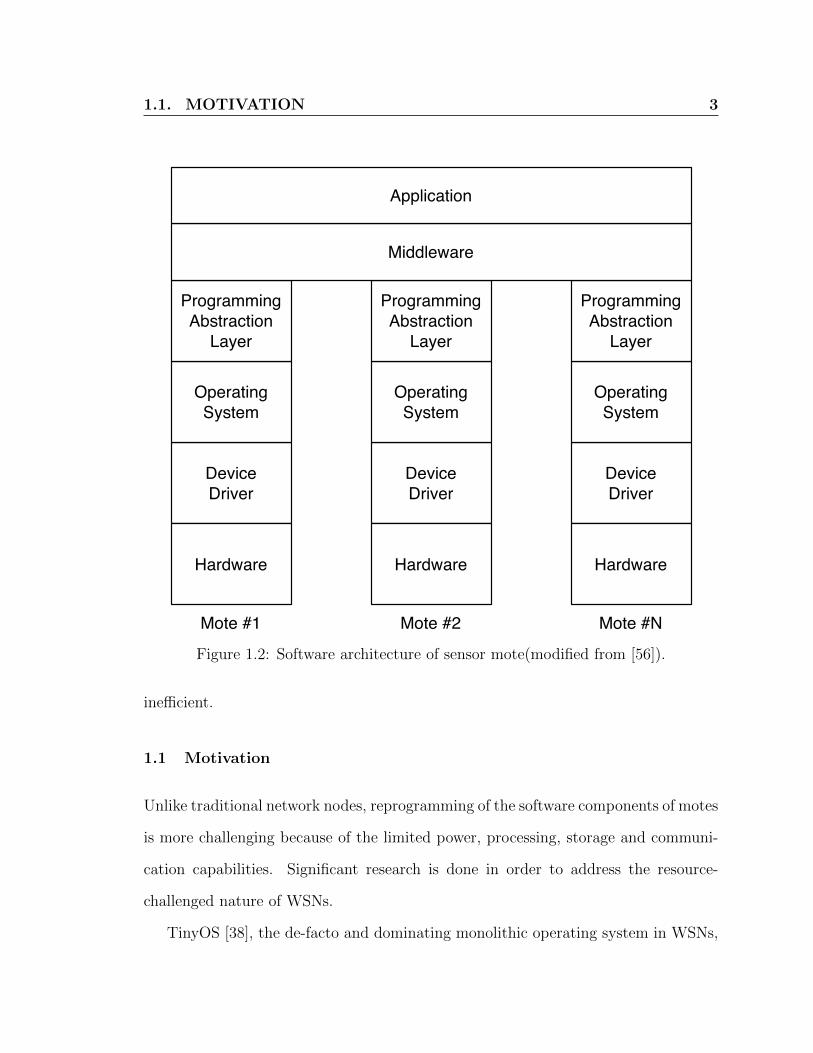
The overall software stack of a WSN mote is composed of three layers. First,
the bottom-most layer, is the operating system. The scope of operating system is
confined to each mote as it provides an interface between hardware (device drivers)
and application layers. Second, the middle layer, glues the operating system provided
abstract with the application layer. Third, the top layer, is the WSN application layer
wherein the network application resides. The scope of middleware and application
layers is the whole sensor network. Fig.1.2 shows the overall software architecture.
Development and deployment of the WSNs is tightly coupled with the desired
application(s). The nature of application development requires frequent updates (re-
programming) of its software components. These updates can be small fixes, few
lines only, e.g. bug fixes, or bigger, e.g. frequent code updates, new components
and new applications. Unlike conventional networks, WSNs are deployed in diverse
environments therefore manual collection and update of motes is both costly and
1.1. MOTIVATION 3
DeviceDriver
Hardware
OperatingSystem
ProgrammingAbstraction
Layer
DeviceDriver
Hardware
OperatingSystem
ProgrammingAbstraction
Layer
DeviceDriver
Hardware
OperatingSystem
ProgrammingAbstraction
Layer
Middleware
Application
Mote #1 Mote #2 Mote #N
Figure 1.2: Software architecture of sensor mote(modified from [56]).
inefficient.
1.1 Motivation
Unlike traditional network nodes, reprogramming of the software components of motes
is more challenging because of the limited power, processing, storage and communi-
cation capabilities. Significant research is done in order to address the resource-
challenged nature of WSNs.
TinyOS [38], the de-facto and dominating monolithic operating system in WSNs,

1.1. MOTIVATION 4
provides native reprogramming facilities (deluge [26]). The deluge, mainly to conserve
memory, is tightly coupled with a TinyOS application. However, due to tight cou-
pling, a minor software update requires complete retransmission and reprogramming
of the mote. For instance, the simple Blink application (periodic blinking of an LED)
without and with deluge is 2128 bytes and 35 kilobytes, respectively. Any modifica-
tion would require the base-station to transmit the new Blink with deluge, i.e. 35
kilobytes, for every node in the network. This consumes significant communication,
processing and storage resources.
An alternate solution is modularization of the mote’s operating system architec-
ture. This results in transmission of only modified modules which then are linked
and loaded by the OS. However, such feature is only available in modular operating
systems. Currently, operating system modularity in WSNs is supported by very few
systems, SOS [23], LiteOS [6] and RETOS [7]. However, these operating systems have
limited visibility. Contiki [18], an emerging alternate to TinyOS, supports modularity
but at cost of extra flash storage and processing. The extra storage is for keeping
track of the symbol table. Processing overhead arises from various book-keeping
tasks to resolve cross referenced symbols that are required for linking and loading of
new module. Furthermore, the granularity of any software update is still confined to
transmission and dynamic linking and loading of the updated module.
Any existing reprogramming approach requires full flash memory rewriting and
consumes significantly higher power and time. Flash memory writing requires a spe-
cific voltage, higher than the microcontroller required voltage, mainly to ensure safe
memory writing. Furthermore, these schemes consume large portions of available
external memory to store the golden image and associated patches. Such storage
1.2. THESIS CONTRIBUTION 5
overlaps and limits other critical operation and functional capacity of the network,
e.g. store and forward routing [12,20,45,52], event logging [10,11,54] and real-time de-
bugging support [9]. In addition, writing to an external memory is slow and requires
significantly more power than writing to other kinds onf memory. Any additional
external memory solely for reprogramming would result in increased mote size, cost
and power requirements.
Although some existing over-the-air reprogramming schemes require less data
to transmit, they may actually increase the size of program’s code. Furthermore,
they may also require a change in the compiler. For instance, Elon [14], requires to
change the networked embedded systems C(nesC) [21] compiler. Other reprogram-
ming schemes, introduce complex bootloader and extra jump tables [49,51], tradeoffs
such as large volume of stored meta data for smaller patches [13] and code fragmenta-
tion [34]. Furthermore, all of the existing reprogramming schemes perform extremely
poor and produce large patches, if function or variable layouts are changed.
1.2 Thesis Contribution
Our research aims primarily at devising an efficient over-the-air reprogramming scheme
for WSNs to produce small size patches without the need of whole flash memory
rewriting, large amount of external memory storage, complex bootloader and com-
piler changes. The objective is to provide remote over-the-air reprogramming of WSNs
motes while reducing the complexity and energy consumption, to prolong the lifetime
and operational capacity of network.
The main contribution of this thesis is devising and implementing an energy-
efficient and low-complexity over-the-air reprogramming scheme, namely QDiff (Queen’s
1.3. ORGANIZATION 6
DIFFerential). The proposed QDiff scheme calculates the minimum size patch by
keeping maximum similarity between two programs, old and new, using clone de-
tection. Clone detection is used to find similar functions and variables hence, to
re-organize function and variable layout to keep the maximum similarity between old
and new programs. New functions or variables are padded at the end of the program.
Most of the existing reprogramming mechanisms fail to handle global variable shifting
due to insertion or deletion of variables. QDiff proposes a new re-organization way
of global variables which efficiently eliminates the problem of global variable shifting.
These two approaches drastically reduce the size of patch, while facilitating maximum
possible function and variable layout changes.
To evaluate the performance, we have implemented QDiff in TinyOS [38] using an
IRIS [65] mote platform and compared with prominent over-the-air reprogramming
schemes for WSNs. As comparison metrics we use patch size, frequency of flash
writings, size of external memory, and consumed time and energy. We also investigate
the overheads of the QDiff approach of reprogramming.
1.3 Organization
The remainder of this document is organized as follows. Chapter 2 presents back-
ground and literature survey of reprogramming in WSNs. Chapter 3 introduces the
QDiff scheme and presents the working details. Chapter 4 presents implementation
details, evaluation methodology and experimental results. Finally, Chapter 5 con-
cludes this document by highlighting the main issues addressed in the thesis and
outlining some of the future research directions.

7
Chapter 2
Background and Literature Survey
2.1 Background
In this section, we briefly present some basic definitions and explain over-the-air re-
programming in wireless sensor networks.
Monolithic System: In a monolithic system, OS kernel and other components
are joined together in a single system image. No barrier or privilege restrictions exist
amongst the modules, i.e. each module can directly invoke any other module [59].
Typically, a monolithic system follows static design approach i.e. all system param-
eters should be specified at design time. Monolithic architecture is suitable where
system updates are less frequent. Fig. 2.1-a shows the monolithic architecture.
Modular System: In a modular system, the OS is split amongst different in-
teracting modules with minimum possible kernel size. The partition between kernel
and other OS parts is performed at design time. The kernel provides with some basic

2.1. BACKGROUND 8
Communication Stack
DeviceDrivers
Application1
Application2
Kernel SensorInterface
(a) Monolithic architecture
Communication Stack
DeviceDrivers
Application1
Application2
Kernel SensorInterface
(b) Modular architecture
Figure 2.1: Operating system architecture for wireless sensor networks.

2.1. BACKGROUND 9
and mandatory functionalities e.g. scheduler, dynamic loading or unloading of mod-
ules, hardware access interface, communication stack, and so on. Other common OS
functionalities, e.g. power management, file system, advanced network protocol, etc.
are implemented as external library and modules. These modules and libraries are
loaded and linked by the kernel on need basis. Interaction between different modules
are supported via indirection table provided by jump table and maintained by the
kernel. Fig. 2.1-b shows the modular architecture.
Virtual Machine: It is a software implementation of a machine (i.e. a mote) which
executes programs like a physical machine and in complete isolation of the host OS.
Virtual machines can either be a single process, group of processes or whole operating
system. The prominent example of virtual machines is Java Virtual Machine (JVM).
JVM runs over the native machine as it executes the java bytecodes. Similarly, the
virtual machine in WSNs runs over the native OS of the mote while executing the
bytecodes. The bytecodes are instruction sets which have one-byte opcodes followed
by optional parameters. Bytecodes may often be directly executed on a virtual ma-
chine (i.e. interpreter), or it may be further compiled into machine code for better
performance. An overview of virtual machine layers, in context of others, is shown in
Fig. 2.2.
Symbol Table: The compiler keeps track of all identifiers, e.g. variables, labels,
functions and their properties e.g. value, type, scope, address, etc. in the symbol
table. It plays an important role in linking of object files into a single executable file.
The symbol table is also used for re-engineering and debugging purposes.

2.1. BACKGROUND 10
Application
Virtual Machine
Native Operating System
Hardware
Figure 2.2: Virtual machine with other layers.
Linking and Loading: Linking means creation of a single executable file from
multiple object files. The compiler parses each file and creates intermediate object
files. Each object file has its own symbol and relocation table. The linker uses these
tables to resolve identifier addresses, values and scope in order to create an executable
file. Loading means the procedure of loading the executable file at some memory ad-
dress for processing unit to start execution.
Pre-linking: Dynamic linking and loading results in significant performance degra-
dation of system. To improve system performance, the kernel caches previous linking
and loading information, hence significantly reducing the linking and loading time.
To maintain system integrity, before re-loading, the system needs to be notified of
any updates.

2.1. BACKGROUND 11
Dynamic Linking and Loading: Dynamic linking and loading facilitates on-
demand loading of various OS modules, hence reducing memory requirements. In
dynamic linking and loading, each module maintains its own symbol table which is
used to resolve any cross references. In WSNs, dynamic symbol resolution results
in overall system degradation as, for every resolution, it may require reading certain
modules from external flash memory. The kernel reads the module from external
flash using peripheral interfaces, generally through Serial Peripheral Interface(SPI).
Moving data between external and internal flash memory is both time and energy
consuming. Furthermore, unloading of an unused module introduces extra overhead.
Initializer: The initializer describes the entry point from where system starts the ex-
ecution of the program code. Functional requirements of an initializer is highly system
dependent. In the context of WSNs, an initializer performs the following main tasks:
load global variables to RAM, initialize the interrupt vector table, initialize devices in
sensor mote and start the main routine’s execution from a pre-determined entry point.
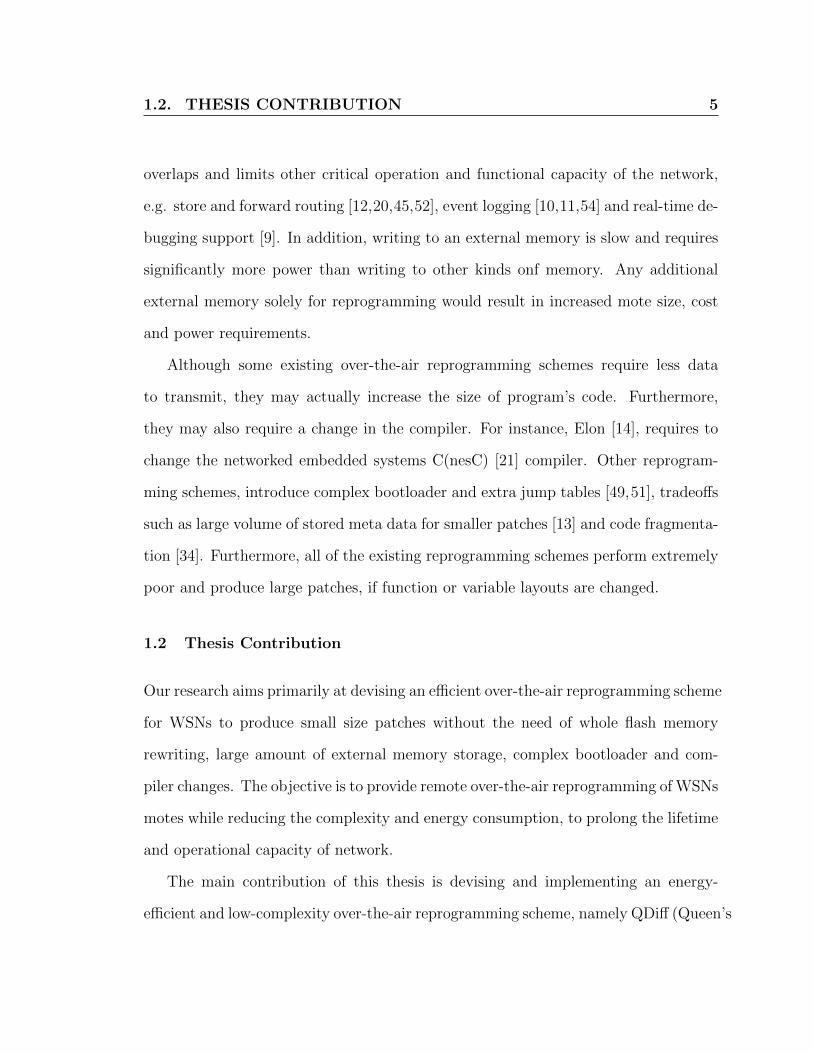
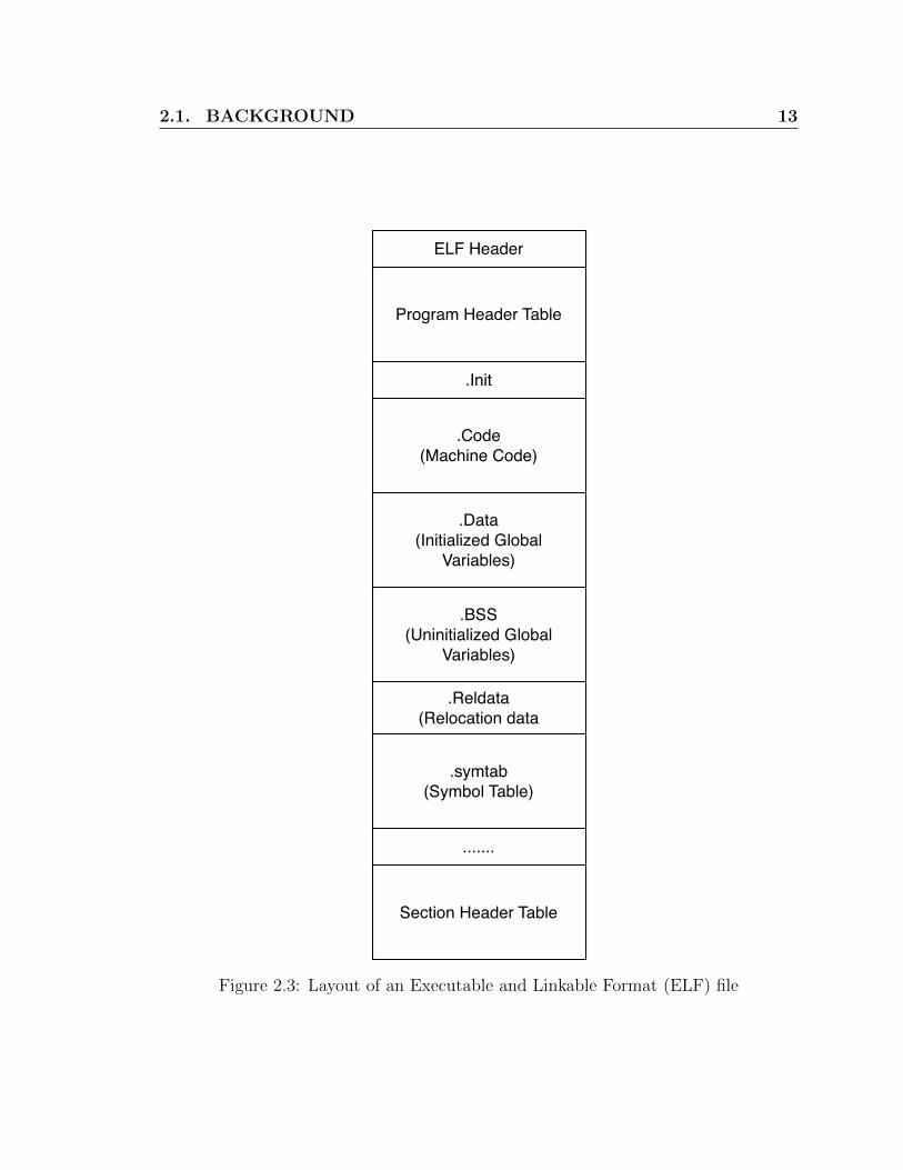
Executable and Linkable Format (ELF): The Executable and Linkable Format
(ELF, formerly called Extensible Linking Format) is a common standard file format
for executables, object code, shared libraries, and core dumps. An ELF file contains
many segments, as shown in Fig. 2.3 and are explained below.
• Program Header: The program header contains generic information for the rest
of the ELF file.
• Section Header: The section header contains the information of a particular

2.1. BACKGROUND 12
section. The section includes code section, data section and symbol table sec-
tion.
• rodata: This section contains constant string, e.g. used by printf statements.
• reltext: This section contains relocatable code.
• .Code: This section contains the machine code, i.e. the executables.
• .BSS: This section contains the uninitialized global variables.
• .Data: This section contains the initialized global variables.
• .symtab: This section contains symbol table, list of different identifiers, and
their properties, i.e. address, value, and scope.
Watchdog Timer: The watchdog timer is a fail-safe mechanism in embedded
systems. The watchdog timer, in case the system goes into an undefined state, is used
to restore (reset) the system to an acceptable state.
Golden Image: The golden image is the latest software version that ran successfully
on the mote. In case of any problem, e.g. software bug, the watchdog timer is used
to flush out existing image and replace it with the golden version.
Clone Detection: Clone detection is a software re-engineering approach to detect
code similarity between two versions. Generally, clones are classified into following
four classes:
• Type 1 clone: Two codes are almost similar except for some differences in white
spaces and comments.
2.1. BACKGROUND 13
Program Header Table
ELF Header
.Init
.Code(Machine Code)
.Data(Initialized Global
Variables)
.BSS(Uninitialized Global
Variables)
.Reldata(Relocation data
.symtab(Symbol Table)
.......
Section Header Table
Figure 2.3: Layout of an Executable and Linkable Format (ELF) file

2.2. LITERATURE SURVEY 14
• Type 2 clone: Identifier names, e.g. variables and functions have been changed
along with white spaces and comments.
• Type 3 clone: Addition (or deletion) of one or more lines of code or functions.
• Type 4 clone: Significant code change with minor structural similarity.
2.2 Literature Survey
Wireless reprogramming is an active research area and can be classified into dissem-
ination protocols and reprogramming schemes. Dissemination protocols are used for
efficient and low-power transfer of patch updates to motes within the deployed WSNs.
Reprogramming schemes can further be classified as system level, module level, vir-
tual machine and differential approaches. The overall classification of wireless re-
programming is shown in Fig. 2.4. In rest of this section, we survey the prominent
dissemination protocols and over-the-air reprogramming schemes.
2.2.1 Dissemination Protocols
XNP [27] is a single-hop reprogramming protocol. In XNP, upon receiving the patch
packets, the sensor mote re-broadcasts to its own neighbours. Any missing or cor-
rupted packet is requested directly from the base-station. Due to the broadcast
nature of the protocol, XNP has significant communication overheads. Trickle [39] is
the first multi-hop code dissemination protocol for reprogramming WSNs. Although
it alleviates the broadcasting problem, it can only transmit small size patches.
Deluge [26] is an extension of the Trickle protocol. Deluge is a well known and
widely used multi-hop code dissemination protocol for bulk data transfer. Deluge

2.2. LITERATURE SURVEY 15
Wireless
Reprogramming
Reprogramming
Techniques
Dissemination
Protocol
XNP [27]
Trickle [39]
Deluge [26]
Stream [50]
DifferentialVirtual MachineModule Level
(Modular)
System Level
(Monolithic)
Contiki [18]
SOS [23]
RETOS [7]
LiteOS [6]
Rsync [60]
Zephyr [51]
Hermes [49]
R2 [13]
Mate [40]
DaVim [46]
TinyOS [48]
Nano-RK [19]
Figure 2.4: Classification of over-the-air reprogramming in WSNs.
reduces transmission time by using pipelined data transfer. Deluge transfers the
whole software image while reprogramming. Moreover, Deluge is tightly coupled
with the software of the sensor mote in the final executable file. Due to this tight
coupling, binary code of Deluge is indirectly transmitted over the network in every
software update. Therefore, overall data transmission is very large, which results in
a large number of energy hungry flash writings.
Stream [50] improves on the shortcomings of the Deluge protocol. Stream isolates
the reprogramming protocol from the application hence, overcomes the problem of
sending reprogramming protocol with every update. To enable this, the reprogram-
ming protocol is consistently stored in mote’s external memory (if available). The

2.2. LITERATURE SURVEY 16
Stream protocol requires complete transmission of application even for small changes.
2.2.2 System Level Reprogramming
In system-level reprogramming, the existing software is completely replaced by an
updated system. The updated system, stored in external flash memory, is copied into
internal flash memory upon system restart. System-level reprogramming is highly in-
efficient as a very small update in the existing system requires replacing the whole ex-
isting system. Existing monolithic operating systems, e.g. TinyOS and Nano-RK [19],
due to their single image file, can make use of the system level reprogramming tech-
nique. Certain non-monolithic operating systems, e.g. Mantis [3], also depend on
system-level reprogramming due to the lack of support of more advanced reprogram-
ming techniques. Even for minor code changes, system-level reprogramming requires
whole image transmission, requires more power and time and has significantly higher
flash memory writings. Furthermore, the mote, to store the complete system image,
requires additional external flash memory. The system-level reprogramming approach
however, is simple and provides better reliability. Also due to complete flushing, sys-
tem developers need not to be worried about illegal data-access, illegal jumps and
complex bootloaders.
2.2.3 Virtual Machine Based Reprogramming
In virtual machine based WSNs, each mote runs an instance of the virtual machine.
The virtual machine is used for execution of both on-network packets and bytecode
instructions. Mate [40] is the first virtual machine in WSNs built on TinyOS. Mate
receives instructions in the form of network packets called capsules. The capsule, 23

2.2. LITERATURE SURVEY 17
bytes in length, contains any code update or patches. Another WSNs virtual machine
namely, VM* [35] adopts the JVM architecture. More in-depth technical details of
WSNs virtual machines can be found in [5, 46, 47,58].
Minimum data transfer is required to update an application running on a vir-
tual machine. However, the nature of virtual machines demand significantly high
processing time and capabilities to be provided by the mote’s CPU. Furthermore,
the reprogramming scope of virtual machine is limited only to very few high-level
instructions.
2.2.4 Modular Reprogramming
Contiki is the first WSNs operating system to support modular update and consists
of two main components: system core and loaded program. The Contiki Core, with
exception of the bootloader, is a non-reprogrammable component [18]. Therefore,
any code change to the kernel, program loader, symbol table and communication
interfaces is not supported. However, enhanced functionalities, e.g. file system sup-
port, shell support, power management are loaded modules and are reprogrammable.
The Contiki follows a customized version of ELF format [37], known as Compact
ELF(CELF) [16]. The CELF file contains all relocation information which is used
by the program loader to obtain information about the module memory size require-
ments and to load it into code flash. Furthermore, the relocation information is used
to update the symbol tables. For greater flexibility, these modules are designed in a
loosely-coupled manner and communicate via the kernel. Although this introduces an
extra level of indirection, it allow more flexiblility in modular reprogramming. Contiki
also introduces dynamic linking and loading, an important feature to support modular
2.2. LITERATURE SURVEY 18
reprogramming. In [61], GZIP is proposed, which is a zip and unzipping mechanism
specially designed for code transfer. As dynamic linking and loading causes some
performance degradation, the authors of reference [15] propose to perform linking
and loading by using pre-linking data. Usage of pre-linking data saves large amount
of time and energy. Furthermore, the modular approach adopted by Contiki results
in larger CLEF files, maintaining additional symbol table(s) and modules security
concerns.
Similar to Contiki, SOS [23] also adopts the modular approach. In SOS, each
module has a well defined entry and exit point and designed in a loosely coupled
manner. Interactions among modules are accomplished via message passing, direct
calling of registered functions of modules or kernel system calls. All modules imple-
ment functions for two common messages, “init” and “final”. Functions for “init”
and “final” set the module’s initial state and release all resources acquired by mod-
ule, respectively. Messaging is highly flexible and asynchronous and provides greater
independence among modules. But, this flexibility and independence come with slow
response. Sometimes synchronous action from different modules is required to per-
form certain tasks. Message passing is not a suitable option in this case. To solve
this issue, SOS allows modules to register some function of other modules. A module
can call these registered functions directly. Modules have to access the kernel via a
jump table which introduces additional indirection.
Modules in SOS use position independent code and provide more flexible and
robust way of interaction among different modules. Position independent code [37]
can be properly executed regardless of the memory position. Executable files with
relocation information are larger in size compared to the executable files with position

2.2. LITERATURE SURVEY 19
independent code as position independent code requires no relocation information.
LiteOS [6] and RETOS [7] use the Contiki memory relocation approach, however
unlike Contiki, LiteOS uses Intel HEX(iHEX) format [37] to store relocation informa-
tion. HEX files requires lower memory size than the ELF file. Furthermore, LiteOS
provides Unix-like abstractions, hence, updating a module is highly user friendly. User
modules can access a system resources through a special type of function pointer call-
gate [6]. RETOS uses non-standard file system for storing relocation information.
Other operating systems, e.g. CORMOS [67], AmbientRT [25] also follow a dynamic
and modular architecture. Dynamic TinyOS [48] attempts to achieve modular archi-
tecture within TinyOS.
The modular architecture is suitable for over-the-air reprogramming. Unlike the
monolithic architecture, any system change is local, only the updated modules need
to be transmitted. However, a large-memory footprint and slow system execution
are inherent disadvantage of any modular system. Reliability is also another issue as
buggy or poorly tested module might cause the whole network to crash. A possible
approach to security, reliability and undefined system behaviour is using frequent
restarts using a watchdog timer at the cost of higher power consumption and data
loss for the motes.
2.2.5 Differential Reprogramming
In the differential reprogramming scheme, the base-station generates a patch using
the difference between the old and updated program. Rsync [60] is a well known
differential update scheme that is widely used in desktops and servers. The Rsync
divides the program into different blocks and calculates the hash value of those blocks.

2.2. LITERATURE SURVEY 20
The hash values are then matched to determine the block’s insertion, deletion, or
modification. In reference [28], the authors present a rsync-based scheme to generate
small sized patch. However, this scheme does not produce an optimal result as it
discards ELF the file structure while calculating diff. It requires rewriting the whole
flash memory as well as a large amount of external flash memory. Moreover, the
scheme is not optimized for call, jump and function rearrangement.
In reference [34], the authors propose a differential scheme, which changes the
linking procedure and keeps a slop1 region after each function to reduce the patch
size caused by call and jump instruction. This scheme creates a small patch, however
it causes fragmentation of flash memory. Moreover, since the size of the slop space is
heuristically assigned, which leads to inefficient utilization of flash memory.
Zephyr [51] keeps a jump table via which all call and jump go to their destination.
This mechanism reduces patch size along with mote’s energy and processing require-
ments. However, the scheme shows poor performance with applications with loops,
which is common in WSNs. Hermes [49], an improvement to Zephyr, removes the
slop region for global variables and jump table at the cost of a complex bootloader. A
complex bootloader requires significantly larger boot memory. Moreover, zephyr and
Hermes both require complete flash memory rewriting and a large amount of external
memory.
Elon [14] overcomes the restart requirement of earlier schemes while also reducing
flash memory access. Elon divides the system into two different components namely,
replaceable and non-replaceable. The core of the operating system is considered non-
replaceable and other parts are considered replaceable components. Although Elon
does not require mote restart, it is highly platform specific. For instance, currently the
1Slop region means free space

2.2. LITERATURE SURVEY 21
scheme, by design, can only work on a TelosB mote running TinyOS. Furthermore,
Elon also requires significant changes in the compiler to support new programming
language syntax.
R2 [13] reduces the patch size by using an efficient implementation of dynamic
loading and linking modules. The R2 scheme maintains meta-data regrading change-
able information and the difference of this meta-data is transmitted to motes. Using
meta-data eliminates the need of a jump table, which is a typical requirement of
Hermes or Zephyr, and complex bootloaders. However, this scheme requires full flash
memory writing. Moreover, a significantly large amount of code flash memory is
required to maintain the meta data.
All of the aforementioned schemes perform poorly when there is a change of pro-
gram and variable layout, require full flash memory writing and large amount of
external flash memory. Our proposed scheme avoids such difficulties by re-organizing
global variables, figuring out the difference using clone detection and maintaining
maximum similarity between two versions of software.

22
Chapter 3
QDiff: A Differential Reprogramming Scheme
3.1 Introduction
The focus of our work is to propose an efficient reprogramming scheme for WSNs. The
efficiency is defined in terms of small patch size, near zero external flash reads/writes,
minimum internal flash reads/writes and the elimination of a system restart after ap-
plying the patch. We call our scheme Queen’s DIFFerential (QDiff) reprogramming.
QDiff is a differential-based reprogramming scheme, which utilizes clone detection
to determine code changes efficiently. Furthermore, QDiff handles branches, global
variables, indirect addresses and relative branches by amending the ELF format in
a manner which is compatible with standard ELF. These effective amendments dra-
matically reduce the internal flash memory usage and require near zero external flash
memory. Furthermore, the wireless sensor motes require no restart after applying the
QDiff generated patch.
The remainder of this chapter is organized as follows. Section 3.2 outlines the
problems and objectives of the differential reprogramming scheme. Section 3.3 ex-
plains the proposed scheme(QDiff). Section 3.4 describes the patch creation process

3.2. MOTIVATION, PROBLEM AND OBJECTIVE 23
and using examples, explains the QDiff approach to handle changes in program line of
code, functions, branches, global variables, indirect addresses, and relative branches.
Section 3.5 explains the QDiff approach of applying the generated patch.
3.2 Motivation, Problem and Objective
Motivation:
Traditional differential utilities, e.g. Unix diff, kdiff are based on the Longest Common
Sub-sequence(LCS) algorithm, that calculates a “delta” between two files without
structural consideration. For instance, simply moving a function location within
the code, results in a large patch. Another well known differential utility is rsync.
Rsync is based hash value calculation. In rsync, two programs “old” and “new”,
are divided into blocks and a hash value is calculated for each block. By comparing
these hash values, a patch is generated for the updated code. Rsync-based differential
approaches are considerably faster than the LCS-based approaches. However, they
are less accurate.
Traditional differential approaches are designed for desktops and servers, wherein
having a patch of few kilobytes (or even megabytes) in size is the norm. However,
this is a serious issue for the motes in the wireless sensor networks, due to their con-
strained resources, functional limitations and unconventional tradeoffs. For instance,
mote designers rely more on computation than transmission, since transmission of
one byte of data is more costly, in terms of energy, than executing thousands of in-
structions [32]. Similarly, flash memory read and write, both internal and external,
consume significant power. Moreover, the flash memory writing is a block based
mechanism, i.e. even if a single byte is changed, the whole block must be rewritten.

3.2. MOTIVATION, PROBLEM AND OBJECTIVE 24
Furthermore, flash memory writing requires higher (2.7V) than minimal operational
voltage (1.7V), at which its behaviour is unpredictable. In GreenOrbs [42] WSNs
application, researchers found that for the TelosB [53] WSN mote, the network life-
time is reduced from 40 days to 11 days upon using a reprogramming protocol with
full flash memory writing [14]. Therefore, reducing flash writing reduces the energy
consumption of the mote, hence allowing more of the mote reprogramming while
maintaining the network lifetime. A large number of reprogramming schemes have
been proposed in the literature [49,51,57], however all of them require flash rewriting
and system restart. To the best of our knowledge, our proposed approach is the first
scheme which produces such a small patch, does not depend on flash rewritings and
does not require mote restart.
Problems:
A single line of code change, in a high-level programming language, may cause a
significantly larger change at the lower-level, e.g. assembly code. To address this,
existing solutions [14, 34, 51] require changes in the programming language syntax
or the compiler itself and hence applies only for certain platforms. A heterogenous
solution, on the other hand, although independent of compiler and mote architecture,
needs to solve the following technical issues:
• Functions: The compiler might change its functional layout for optimization
purposes resulting in a large patch file. Moreover, these changes shift the ma-
chine code in the final ELF file. Furthermore, even a small change, e.g. insertion
of single instruction, may shift all of its subsequent instructions and branch ad-
dresses. This will yield significantly large patch file whose deployment would

3.2. MOTIVATION, PROBLEM AND OBJECTIVE 25
require full rewriting of internal flash.
• Global variables: During the creation of an executable file, the compiler consid-
ers the global variables in two contexts: initialized and uninitialized. Initialized
global variables are kept in the data section, and uninitialized global variables
are kept in the bss 1 section. To optimize memory space, both of these sections
(data and bss) are kept back-to-back without any slots in the memory space.
Due to this, any addition in data section, e.g. a new variable, shifts the address
of all variables within the bss section. Furthermore, the shift also modifies all
instructions that reference the shifted variables, hence results in a very large
patch file. Moreover, there is no assurance that a compiler will keep the same
variable layout every time the program is compiled.
• Relative jumps: The relative jump range is calculated using the current memory
location. Based on current memory address a relative jump can either be a
positive offset or a negative offset. Positive offset means that the jump target
address is higher than the current address. Negative offset means that the
jump target address is lower than the current address. Addition or removal of
any new or existing instructions, between the current memory location and the
target location, will result a change in the jump offsets. This happens even if
the instructions at the target location has not been modified, hence resulting in
unnecessary large patch file.
• Indirect addresses: Indirect addressing is an important part of the load-store
architecture of the Reduced Instruction Set Computing (RISC) machine. The
1Bss section is a part of ELF file. Historically, BSS(Block Started by Symbol) was a pseudo-operation in an assembler, developed for the IBM 704.

3.3. QDIFF: DIFFERENTIAL-BASED REPROGRAMMING SCHEMEUSING CLONE DETECTION 26
RISC architecture does not allow to direct access to the memory location. Mem-
ory locations are accessed or modified using registers. Indirect addressing pro-
vides fast access to large data structures, e.g. arrays, linked lists, union, etc.
However, any changes in the global variable layout will also change the corre-
sponding indirect instructions and must be taken care of in order to produce
correct patch files.
Design Goals:
The main objectives of the differential-based reprogramming scheme are as follows:
• Minimizing difference size, as small difference means less energy and time to
reprogram the network.
• Minimizing flash memory writing, as flash memory writing is energy hungry
and reduction of flash memory writing means better energy and time efficiency.
• Minimizing external flash requirement, as reducing external flash usage means
reducing cost, as well as reducing requirement for board real estate.
• Supporting heterogeneity as many different hardware platforms and operating
systems are available for wireless sensor networks, with diverse specifications.
• Eliminating the need for mote reboot after applying the patch on mote software.
3.3 QDiff: Differential-based Reprogramming Scheme Using Clone De-
tection
A differential-based reprogramming scheme consists of several major steps. These
are, receive old and new files from code database, calculate the patch using an “al-
gorithm”, compress and encode patch, store (old, new, patch) tuple in the database
3.3. QDIFF: DIFFERENTIAL-BASED REPROGRAMMING SCHEMEUSING CLONE DETECTION 27
Database
Diff Tool
Old Program New Program
Compress &Disseminate
Receives Patch
Apply Patch viaBootloader
Restart Application
Base-station Mote
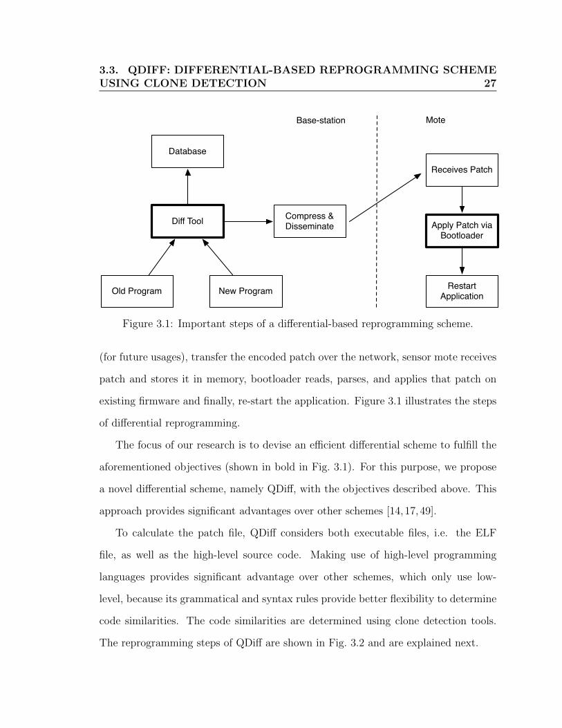
Figure 3.1: Important steps of a differential-based reprogramming scheme.
(for future usages), transfer the encoded patch over the network, sensor mote receives
patch and stores it in memory, bootloader reads, parses, and applies that patch on
existing firmware and finally, re-start the application. Figure 3.1 illustrates the steps
of differential reprogramming.
The focus of our research is to devise an efficient differential scheme to fulfill the
aforementioned objectives (shown in bold in Fig. 3.1). For this purpose, we propose
a novel differential scheme, namely QDiff, with the objectives described above. This
approach provides significant advantages over other schemes [14,17,49].
To calculate the patch file, QDiff considers both executable files, i.e. the ELF
file, as well as the high-level source code. Making use of high-level programming
languages provides significant advantage over other schemes, which only use low-
level, because its grammatical and syntax rules provide better flexibility to determine
code similarities. The code similarities are determined using clone detection tools.
The reprogramming steps of QDiff are shown in Fig. 3.2 and are explained next.

3.3. QDIFF: DIFFERENTIAL-BASED REPROGRAMMING SCHEMEUSING CLONE DETECTION 28
Diffuse the patch using disemmination protocol
Sensor mote receives the patchand applies using bootloader
Base-station
Sensor mote
Reorder functions, variables and place new functions and variables at the end of data,
code and bss sections
Calculate delta for the code, data and bss sections
Aggregate all deltas, optimize and calculate minimal
consolidated patch
Disassemble ELF file and findfunctions and global variables
Calculate function and variable clones
Figure 3.2: Major steps of the QDiff differential reprogramming scheme.
3.3. QDIFF: DIFFERENTIAL-BASED REPROGRAMMING SCHEMEUSING CLONE DETECTION 29
1. QDiff calculates clones between the old and the new file using clone detec-
tion tool. The clone detection tool takes in the C file of the old and the
modified program and calculates a mapping between functions and variables.
We assume that the clone detection mechanism has perfect precision. The
C files, in case of TinyOS programming, are generated by the compiler as
it converts the nesC into C before it create the final ELF file. The map-
ping is a list of function and variable clones between the old and the new
file, i.e. FunctionClonePair(FunctionOld, FunctionNew) and VariableClone-
Pair(OldVariable, NewVariable). The clone detection algorithm can detect
clones under various circumstances, e.g. change in file layout, rename of func-
tions and variables, addition or removal of one or more lines of code, etc. For
this thesis, we emphasize “Type 3” clone detection as it can detect addition and
removal of new code, functions and variables.
2. QDiff disassembles the ELF files (both old and modified), using the core dump
utilities, to determine different sections, i.e. code, data and bss. In this step,
mappings between functions and global variables, computed from the clone
detection step are used for the function and the variable reordering. This step
is further subdivided as follows:
(a) Reorder functions and global variables to enhance the similarity between
old and new programs. Place new functions, initialized and uninitialized
global variables at the end of the code, data and bss sections respectively.
(b) Change all references to the re-ordered functions and variables. For in-
stance, if a call instruction invokes a function func1 at address 0x234 and

3.4. QDIFF PATCH CREATION PROCESS 30
reordering caused the change of func1 location to 0x456, all call instruc-
tions invoking func1 change their destination address to 0x456. A similar
approach is taken for global variables.
(c) Modify the organization of uninitialized global variables, i.e. variables in
the bss section. Organize uninitialized global variables in stack fashion.
Place new variables at the top of the bss section.
(d) Calculate the delta between the old and the new code section. This includes
clone functions and newly added (or removed) functions.
(e) Calculate the delta between the old and the new data section. This includes
added, deleted or modified initialized variables.
(f) Calculate delta between old and new bss section. This include added,
deleted or modified uninitialized variables.
(g) Aggregate all deltas and calculate the final patch file. The file is optimized
to minimize the patch size and flash memory access.
3. The base-station transmits the patch file over wireless medium, which is dis-
persed through whole network using an existing dissemination protocol.
4. Sensor mote receives the patch file and invokes the bootloader, which applies it
without rebooting the mote.
3.4 QDiff Patch Creation Process
Our examination of code changes in low-level language shows that a differential patch
creation needs to address four major technical issues: branches, global variables,

3.4. QDIFF PATCH CREATION PROCESS 31
relative jumps and indirect addresses. In this section, we explain how QDiff solves
these issues.
3.4.1 Branches
In this section, we discuss the impact of a code change on branch instructions, i.e.
function call and jump to some absolute address. The code change affects branch in-
structions in two ways. First, an insertion or deletion of new instruction(s) may shifts
all the subsequent instructions. This shift changes all call and jump instructions that
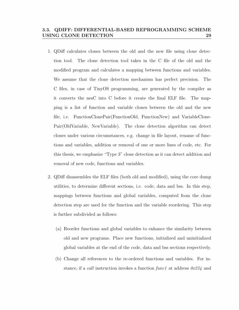
invoke functions or jump to the location in shifted portion. Fig. 3.3 illustrates change
in the functions (funcA and funcB) location due to insertion of the new code, i.e.
from 0x3f2 and 0x4d2 to 0x4f2 and 0x5d2 for funcA and funcB, respectively. This
change modifies all offsets for call instruction, e.g. from “call 0x3f2” to “call 0x4f2”,
for the funcA. Second, the compiler may change the function order during code op-
timization. This reordering changes functions’ locations and subsequently requires to
change all call instructions referring to them. Fig 3.4 illustrates change of function
location due to reordering and hence, subsequent modifications of their respective call
instructions.
QDiff solves both scenarios by appending any modification to the end of the ELF
file. In case of compiler reordering and renaming, the branch related issues are solved
using clone detection. If any new function is added, in the middle of code, QDiff moves
its location and change all branch instruction that are referring to it. The main idea is
to minimize the flash memory writing as only the new functions and the instructions
referring it, need to be rewritten. On the other hand, if new instructions are added
within the function, QDiff modifies the program to bring maximum similarity in two
3.4. QDIFF PATCH CREATION PROCESS 32
Call 0x3f2 //func A:
Call 0x4d2 //func B
func A
func B
0x3f2
0x4d2
Call 0x4f2 //func A:
Call 0x5d2 //func B
Inserted Code
func A
func B
0x4f2
0x5d2
Figure 3.3: Example of function call address change due to code insertion.
Call 0x3f2 //func A:
Call 0x4d2 //func B
func A
func B
0x3f2
0x4d2
Call 0x4f2 //func A:
Call 0x1a0 //func B
0x1a0
0x4f2
func A
func B
Figure 3.4: Example of address change due to function reordering.

3.4. QDIFF PATCH CREATION PROCESS 33
ways. First, if there is a slop region after that function, the function is extended to
that slop region. This slop region has been created due to the deletion of a function.
Second, if there is no slop region, new instructions are moved and padded at the end
of program. From the callee function, new instructions are added by QDiff; jump to
the newly padded instruction and return back to callee function. This is illustrated
in Fig. 3.5.
Old File
New Code
New file
New CodeGCC compiled old file
QDiff generated equivalent file.
0xaaaa
Call 0xaaaa
retColored instructions are added by QDiff
New code
Figure 3.5: Padding newly added code block at the end of program code.
3.4. QDIFF PATCH CREATION PROCESS 34
Code deletion, related to branches, comes in two forms: removal of a complete
function or some code from within a function. In the first case, if the function is
deleted from program, a slop region is inserted in place of the deleted function. The
slop regions facilitate future growth of existing functions or insertion of new functions.
Moreover, this provides more similarity between old and new program and reduces
patch file size. To keep the patch file at minimum the slop regions are kept within or
after the function.
In case of simultaneous addition and deletion of function (or code within) is a
multi-step process. First, the deleted functions are removed from the old program.
This removal creates slop regions within the old program. Second, for the newly
added code to function, all matching slop regions are first determined. Matching
slop-regions refer those slop-regions, whose size is larger or equal to newly added
code/function. To break the tie, QDiff selects the largest region. The slop region
is maximally utilized by inserting maximum possible functions. The maximum slop
region utilization problem is a variant of a typical (0,1) knapsack problem. If there
is no slop region whose size is larger than the function size then the new function is
padded at the end. If some code is inserted in an existing function and the existing
function has some slop region following it, the function is expanded. Otherwise, new
instructions are padded at the end. A call-return pair is inserted into program code
to jump to/from the newly padded instructions. An illustration of QDiff approach
to handle simultaneous insertion and deletion is shown in Fig. 3.6. The algorithm
flowchart is shown in Fig. 3.7.
An exemplary scenario, with addition of multiple functions is shown in Fig. 3.8.
In Fig. 3.8, two program versions are shown wherein the program segment on the left
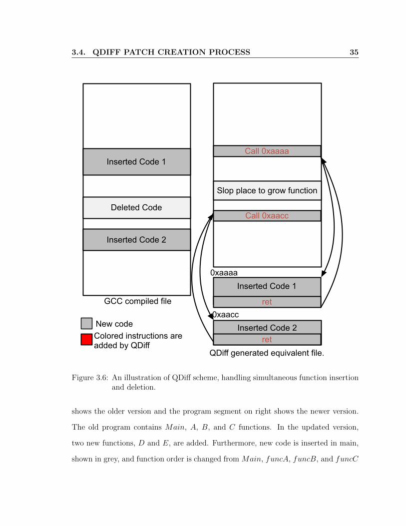
3.4. QDIFF PATCH CREATION PROCESS 35
Inserted Code 1
Inserted Code 1
Deleted Code
Inserted Code 2
Slop place to grow function
Inserted Code 2
0xaaaa
0xaaccGCC compiled file
QDiff generated equivalent file.
Call 0xaacc
Call 0xaaaa
ret
ret
Colored instructions are added by QDiff
New code
Figure 3.6: An illustration of QDiff scheme, handling simultaneous function insertionand deletion.
shows the older version and the program segment on right shows the newer version.
The old program contains Main, A, B, and C functions. In the updated version,
two new functions, D and E, are added. Furthermore, new code is inserted in main,
shown in grey, and function order is changed from Main, funcA, funcB, and funcC

3.4. QDIFF PATCH CREATION PROCESS 36
Begin
Detect all new, deleted, reordered functions and code fragments
using clone detection mechanism.
Reorder functions according to old layout and keep slop region in
place of deleted functions.
Detect all branches from symbol table
Mark all new functions and code fragments as non-filled
Place remaining non-filled functions at the end and update all
branches to those functions
Insert new code fragment in function if there exists a slop region
after function and mark it as filled.
MaxSize[slop region in code] >=
MinSize[Non-filled functions]
Pick the largest slop region and fill it by non-filled
functions using (0,1) knapsack algorithm
Yes
Update slop region size and mark all functions inserted
in slop region as filled.
Change all branches referring to filled functions
No
End
Place remaining non-filled code fragments at the end
All new functions become filled ?
Yes No
Step 1
Step 2
Step 3
Step 4
Step 5
Step 6
Step 7
Step 8
Figure 3.7: Flowchart for fixing branches

3.4. QDIFF PATCH CREATION PROCESS 37
Call 0x4f2 //func A:
Call 0x5f2 //func B:
Call 0x6f2 //func C::
GCC compiled old file
func A
func B
func C
0x4f2
0x5f2
0x6f2
0x0f2Main function
Call 0xaf2 //func A:
Call 0x6f2 //func B:
Call 0x9f2 //func C::
Mov r1,r2Call 0x7f2 //func DCall 0x8f2 //func E
:
func D
func E
0x6f2
0x7f2
0x8f2
0x0f2Main function
func C
func A
0x9f2
0xaf2
:Mov r1,r2
Call 0x9f2 //func DCall 0xaf2 //func E
:
func B
GCC compiled new file
New code
Figure 3.8: An exemplary scenario showing addition of multiple functions.
to Main, funcB, funcD, funcE, funcC, and funcA. Due to the re-ordering all
branching instructions, referring to the reordered functions, are also changed. The
QDiff scheme, following the Pseudocode 3.7, reorders the functions according to the
old order and pad the new functions at the end. The modification also insert a
new call instruction, “call 0xaaf2, in the Main function and a corresponding return
instruction in the padded code block (0xaaf2). As a final step, the effected call and
jump instructions are updated to reflect the new address. These steps, with final ELF
file layout, are illustrated in Fig. 3.9.

3.4. QDIFF PATCH CREATION PROCESS 38
Call 0x6f2 //func A:
Call 0x7f2 //func B:
Call 0x8f2 //func C::
Mov r1,r2Call 0x9f2 //func DCall 0xaf2 //func E
:
GCC compiled old file
func A
func B
func C
0x6f2
0x7f2
0x8f2
0x0f2Main function
func D
func E
0x9f2
0xaf2
Call 0x4f2 //func A:
Call 0x5f2 //func B:
Call 0x6f2 //func C::
Call 0xaaf2
GCC compiled old file
func A
func B
func C
0x5f2
0x6f2
0x0f2Main function
func D
func E
0x7f2
0x8f2
:Mov r1,r2
Call 0x9f2 //func DCall 0xaf2 //func E
:ret
0xaaf2
:Mov r1,r2
Call 0x9f2 //func DCall 0xaf2 //func E
:
QDiff pads new code at the end
New code
Colored instructions are added by QDiff
Call 0xaaf2
Figure 3.9: Illustration of QDiff handling multiple functions.
3.4.2 Global Variables
In this section, we discuss the impact of code change on global variables. In an
ELF file, global variables are kept in two separate sections, the data section for the
initialized variables and the bss section for the uninitialized variables. Both data
and bss sections are kept in heap, which is initialized in the RAM by the initializer
function. In a traditional ELF file, data and bss sections are kept back to back, i.e.
3.4. QDIFF PATCH CREATION PROCESS 39
.data
Code Section
.bss
GCC compiled ELF file QDiff modified ELF file
Free Space in RAM
.data
Code Section
.bss
Free Space in RAM
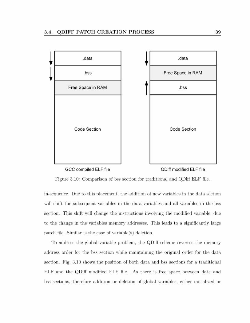
Figure 3.10: Comparison of bss section for traditional and QDiff ELF file.
in-sequence. Due to this placement, the addition of new variables in the data section
will shift the subsequent variables in the data variables and all variables in the bss
section. This shift will change the instructions involving the modified variable, due
to the change in the variables memory addresses. This leads to a significantly large
patch file. Similar is the case of variable(s) deletion.
To address the global variable problem, the QDiff scheme reverses the memory
address order for the bss section while maintaining the original order for the data
section. Fig. 3.10 shows the position of both data and bss sections for a traditional
ELF and the QDiff modified ELF file. As there is free space between data and
bss sections, therefore addition or deletion of global variables, either initialized or

3.4. QDIFF PATCH CREATION PROCESS 40
uninitialized, will not cause any shift in the variables addresses and their subsequent
instructions. Addition, deletion, or re-arrangements of initialized or uninitialized
global variables, similar to branch instructions, may result in code shift.
In case of compiler reordering and renaming, the global variable related issues are
solved using clone detection. If any variable is deleted, it is removed from the heap,
however the location is maintained as a slop region. If a variable is added, QDiff
checks all slop regions, picks up the largest slop region and fill the slop region by
the new variable, using (0,1) knapsack algorithm. If there is no such type of region,
the new variable is added at the end. An initialized global variable is added at the
bottom of data section. Whereas an uninitialized global variable is added at the top
of bss section.
An exemplary scenario for global variable is shown in Fig. 3.11. The left portion
of Fig. 3.11 shows gcc compiled traditional ELF file. In this diagram, two variables
in the data section, Timer Interval and Msg Interval, and two variables in the bss
section, Msg Counter and Temperature, are shown. Memory address range of the
data section, the bss section, and available free space is 0x0f2−0x4f1, 0x4f2−0x6f1,
and 0x6f2 − 0x7f1, respectively. To facilitate global variables, QDiff modifies the
memory address for bss section and available free space. The modification is shown
in the right portion of Fig. 3.11, wherein the data section memory location is the
same as the traditional ELF file. However, both the bss section and the free space
are changed with memory ranges of 0x5f2− 0x7f1 and 0x4f2− 0x5f1, respectively.
The bss section is reversed and kept as a stack, i.e. new variables are assigned lower
memory addresses. Due to this, for the exemplary scenario, the arrangement of
variables are reversed, i.e. the Msg Counter and Temperature are placed at the end

3.4. QDIFF PATCH CREATION PROCESS 41
:
Sts r1,0x00f2 //Timer_Interval
Lds r2,0x00f4 //Msg_Interval
:
:
Sts r3,0x04f2 //Msg_Counter
Sts r4,0x04f4 //Temperature
:
Free Space in RAM
GCC compiled ELF file QDiff modified ELF file
0x00f2
0x04f2
Timer_Interval
Msg_Interval0x00f4
0x06f2
0x07f0
0x04f0
Msg_Counter
Temperature
D
a
t
a
B
s
s
0x04f4
C
o
d
e
:
Sts r1,0x00f2 //Timer_Interval
Lds r2,0x00f4 //Msg_Interval
:
:
Sts r3,0x07f0 //Msg_Counter
Sts r4,0x07ee //Temperature
:
Free Space in RAM
0x00f2 Timer_Interval
Msg_Interval0x00f4
0x07f0
0x04f0
D
a
t
a
C
o
d
e
Temperature
Msg_Counter
B
s
s
0x05f2
0x07ee
New or re-ordered variable
Figure 3.11: Illustration of traditional ELF and QDiff modified data/bss sections.
3.4. QDIFF PATCH CREATION PROCESS 42
:
Sts r1,0x00f4 //Timer_Interval
Lds r2,0x00f2 //Msg_Interval
:
Sts r3,0x04f4 //Msg_Counter
Sts r4,0x04f6 //Temperature
:
:
Free Space in RAM
GCC compiled ELF file QDiff modified ELF file
0x00f2 Msg_Interval
Timer_Interval0x00f4
0x06f2
0x07f0
0x04f2
D
a
t
a
C
o
d
e
:
Sts r1,0x00f2 //Timer_Interval
Lds r2,0x00f4 //Msg_Interval
:
Sts r3,0x07ee //Msg_Counter
Sts r4,0x07f0 //Temperature
:
:
Free Space in RAM
0x00f2 Timer_Interval
Msg_Interval0x00f4
0x07f0
0x04f0
D
a
t
a
C
o
d
e
Msg_Counter
Temperature
B
s
s
0x05f2
0x07ee
0x04f4 Msg_Counter
Temperature
B
s
s
0x04f6
Sense_Interval
Pressure
:
Lds r5,4f2 //Sense_interval
Sts r6,0x6f2 //Pressure
:
:
Lds r5,4f2 //Sense_interval
Sts r6,0x5f0 //Pressure
:
Sense_Interval
Pressure0x05f0
0x04f2
New or re-ordered variable
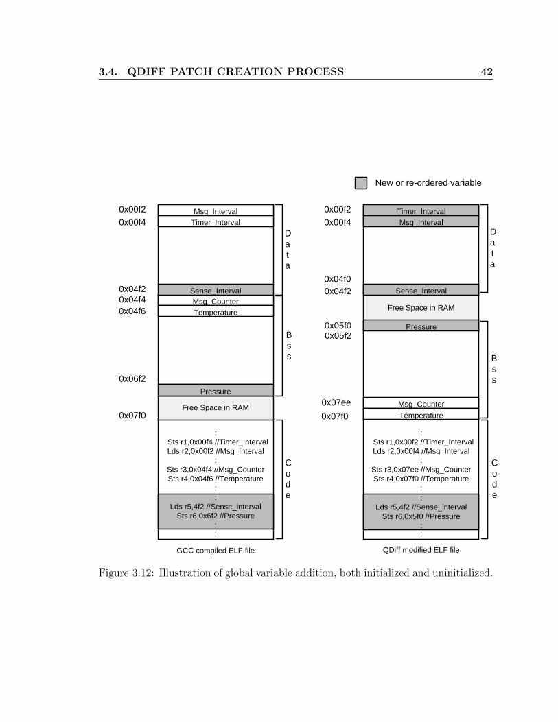
Figure 3.12: Illustration of global variable addition, both initialized and uninitialized.

3.4. QDIFF PATCH CREATION PROCESS 43
of the bss section.
As another exemplary scenario, suppose two new variables are added, one in the
data section and the other in the bss section. As explained above, the standard
ELF file will add these two new variables at bottom of their respective sections, i.e.
Sense Interval is added at the bottom of data section, whereas Pressure is added
at the bottom of bss section. Now assume, after compilation, that the variable layout
is changed, with respect to Fig. 3.11, as shown in the left side of Fig. 3.12. Adding a
new variable in the data section shifts all of the global variables within the bss section,
which further affects all the referring instructions, i.e. the sts and lds instructions
within the code section. The sts instruction stores a register value in an address
location specified in the instruction. The lds instruction loads value from address
specified in instruction to a certain register. The QDiff scheme detects the newly
added variable and the reorganized variable, using clone detection. The layout of the
existing variable Timer Interval and Msg Interval are rearranged according to the
old program order. QDiff adds the new variable, Sense Interval at the bottom of
the data section and Pressure on the top of the bss section. The QDiff scheme also
changes the instructions referring to these newly and reordered variables. The final
modification of variable and code section in shown in right side diagram of Fig 3.12.
Special consideration must be given for memory access via indirect registers. The
indirect registers are used for accessing arrays and large data structure. In QDiff,
the addition of new array in the data section follows the traditional ELF method, i.e.
placed at the bottom of the section. In case of the bss section, the base address of
the array is changed while maintaining the array order. This reduces the complexity
of handling indirect registers with offsets. Fig. 3.13 shows sequence of variables
3.4. QDIFF PATCH CREATION PROCESS 44
.data
Code Section
Free Space in RAM
.bss
New variable at .data section
New variable at .bss section
.bss
AB
C[0]C[1]C[2]D
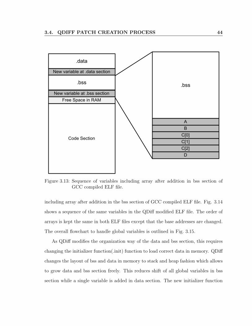
Figure 3.13: Sequence of variables including array after addition in bss section ofGCC compiled ELF file.
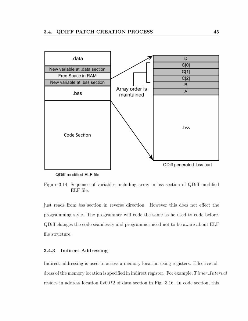
including array after addition in the bss section of GCC compiled ELF file. Fig. 3.14
shows a sequence of the same variables in the QDiff modified ELF file. The order of
arrays is kept the same in both ELF files except that the base addresses are changed.
The overall flowchart to handle global variables is outlined in Fig. 3.15.
As QDiff modifies the organization way of the data and bss section, this requires
changing the initializer function(.init) function to load correct data in memory. QDiff
changes the layout of bss and data in memory to stack and heap fashion which allows
to grow data and bss section freely. This reduces shift of all global variables in bss
section while a single variable is added in data section. The new initializer function
3.4. QDIFF PATCH CREATION PROCESS 45
QDiff modified ELF file
.data
Code Sec(on
Free Space in RAM
.bss
New variable at .data section
New variable at .bss section
.bss
DC[0]C[1]C[2]
BA
QDiff generated .bss part
Array order ismaintained
Figure 3.14: Sequence of variables including array in bss section of QDiff modifiedELF file.
just reads from bss section in reverse direction. However this does not effect the
programming style. The programmer will code the same as he used to code before.
QDiff changes the code seamlessly and programmer need not to be aware about ELF
file structure.
3.4.3 Indirect Addressing
Indirect addressing is used to access a memory location using registers. Effective ad-
dress of the memory location is specified in indirect register. For example, Timer Interval
resides in address location 0x00f2 of data section in Fig. 3.16. In code section, this

3.4. QDIFF PATCH CREATION PROCESS 46
Begin
Detect all new, deleted, reordered global(initialized and
uninitialized) variables using clone detection.
Reorder variables according to old layout and keep slop region in
place of deleted variables.
Detect all instructions referring to global variables
Mark all new initialized and uninitialized global variables as non-
filled
Repeat step 5 for uninitialized global variables
Add remaining non-filled initialized global variables at the end of
data section and change all instructions referring to them.
MaxSize[slop region in data] >=
MinSize[Non-filled initialized variables]
Pick the largest slop region and fill it by non-filled
initialized variables using (0,1) knapsack algorithm
Yes
Update slop region size and mark all variables inserted
in slop region as filled.
Change all instructions referring to filled variables
No
End
Add remaining non-filled uninitialized global variables on top of
bss section and change all instructions referring to them.
All initialized variables become
filled ?
Yes No
Step 1
Step 2
Step 3
Step 4
Step 5
Step 6
Step 7
Step 8
Figure 3.15: Flowchart for fixing global variables.

3.4. QDIFF PATCH CREATION PROCESS 47
address location is loaded in indirect register ir1. As ir1 contains memory location
of Timer Interval, all load/store instructions using ir1 effects Timer interval. In
sub-sequent instruction, st r2, ir1, value of Timer Interval is set by register r2. Typ-
ically, indirect addressing is used for faster access of data. Due to the re-arrangement
of bss section, QDiff modifies indirect instructions referring to bss section. To explain
the working mechanism of QDiff to handle indirect addressing, we use an exemplary
scenario(Fig. 3.16). The left portion of Fig. 3.16 shows the modified global variables,
Timer Interval and Msg Interval. These two variables are set, in the code section,
using indirect registers ir1 and ir2, respectively. Using the global variable procedure
(explained in the flowchart of Fig. 3.15 and shown in right portion of Fig. 3.16),
QDiff changes the memory location of Msg Interval. This change which is required
because of QDiff’s stack-based bss section invalidates the instructions referring to it.
To fix this situation, QDiff detects and modifies such instructions. This modification
can be done through two type of instructions. First, by updating indirect registers
through an immediate value. Second, updating indirect through another register.
QDiff generates control flow graph to detect these two type instructions and modifies
them to refer to new location of corresponding variable. The updated instruction is
shown in the QDiff modified code section wherein the original “mov ir2, 0x04f2” is
changed to “mov ir2, 0x07f0”, 0x07f0 is the new memory location of Msg Interval
variable.
Let us consider another example scenario involving arrays and indirect addressing.
This scenario is shown in Fig. 3.17, wherein two arrays A[0 : 1] and B[0 : 1] are added
in the data and bss sections, respectively. As in previous example, the QDiff scheme
changes the memory location of the B[0 : 1] array, while maintaining the original

3.4. QDIFF PATCH CREATION PROCESS 48
: mov ir1,0x00f2 //Timer_Interval
st r2,ir1 // Set Timer_Interval ::
mov ir2,0x04f2 //Msg_Counterst r4,ir2 //Set Msg_Counter
:
Free Space in RAM
GCC compiled ELF file QDiff modified ELF file
0x00f2
0x04f2
Timer_Interval
0x06f2
0x07f0
Msg_Counter
Data
Bss
Code
: mov ir1,0x00f2 //Timer_Interval
st r2,ir1 // Set Timer_Interval ::
st r4,ir2 //Set Msg_Counter:
Free Space in RAM
0x00f2 Timer_Interval
0x07f0
0x04f0
0x05f2
Data
Bss
Code
Modified
Msg_counter
mov ir2, 0x07f0 //Msg_Counter
Figure 3.16: Illustration of indirect address access and global variables, for traditionaland modified ELF files.

3.4. QDIFF PATCH CREATION PROCESS 49
: mov ir1,0x00f2 //Timer_Interval
st r2,ir1 // Set Timer_Interval :
mov ir2,0x04f2 //Msg_Counterst r4,ir2 //Set Msg_Counter
:
Free Space in RAM
GCC compiled ELF file QDiff modified ELF file
0x00f2 Timer_Interval
0x06f2
0x07f0
0x04f2
Data
Code
: mov ir1,0x00f2 //Timer_Interval
st r2,ir1 // Set Timer_Interval :
mov ir2,0x07f0 //Msg_Counterst r4,ir2 //Set Msg_Counter
:
Free Space in RAM
0x00f2 Timer_Interval
0x07f0
0x04f2
Data
Code
Bss
0x05f0
0x07ee
0x04f4Msg_Counter
Bss
A[1]
B[1]
mov ir1,4f2 //A[0]st r2,ir //Set A[0]
st r3,ir+2 //Set A[1]mov ir1,6f2 //B[0]st r2,ir //Set B[0]
st r3,ir+2 //Set B[1]
0x05ee
0x04f4
Modified
A[0]
B[0]
B[1]B[0]
A[1]A[0]
0x04f6
0x06f4
mov ir1,4f2 //A[0]st r2,ir //Set A[0]
st r3,ir+2 //Set A[1]
st r2,ir //Set B[0]st r3,ir+2 //Set B[1]
Msg_counter
mov ir1, 533 // B[0]
Figure 3.17: Illustration of indirect address access and global arrays, for traditionaland modified ELF files.

3.4. QDIFF PATCH CREATION PROCESS 50
memory order for its element in the memory space. In the code section, these arrays
are accessed through offset addition to the values of the indirect registers. In this
case, QDiff modifies the instructions, that involve the base address. For instance, the
instruction “mov ir2, 0x06f2” is changed to “mov ir2, 0x05ee”, 0x5ee is the base
address of the array B[0 : 1]. However, no change is required for instructions that are
accessing higher index value of array, since QDiff maintains the element order for each
array. For instance, the instructions “st r2, ir” and “st r3, ir + 2” accessing B[0]
and B[1], respectively, remain unchanged. The QDiff algorithm to handle indirect
addressing is shown in flowchart of Fig. 3.18.
In the next iteration of code, two arrays, A[0:1] and B[0:1] are added, A[0:1] is
added in data section and array B[0:1] added in bss section. New arrays are shown in
dark grey color in Fig 3.17. Although the array B[0:1] is added at the end, its order
is maintained same. In the updated code section of Fig. 3.17 shows few instructions
referring the global variables and arrays in data and bss section. Arrays are accessed
through adding offset to the indirect registers. As array order is maintained the
same as in the gcc compiled file, there is no need to change the instructions that
are accessing higher index value of array. In this case, QDiff modifies instructions
dealing with the base address. Other instructions are kept intact. In the code section
of Fig. 3.16 and Fig. 3.17, the ”st” instruction sets different global variable through
different indirect registers, ir1,ir2,ir4...irn. Left side diagram of Fig. 3.16 shows new
gcc compiled file. QDiff detects new and reorganized variables using clone detection
mechanism, then reorganizes the existing variables. Then QDiff adds A[0:1] at the
end of data section and B[0:1] on the top of bss section. After this modification,
QDiff changes indirect instructions referring variables in data and bss section. The

3.4. QDIFF PATCH CREATION PROCESS 51
Begin
Generate a control flow graph of whole program
Traverse control flow graph and keep track of indirect registers
If any indirect instruction encountered, find address stored in
related indirect register.
Address in indirect register in
bss section?
Calculate corresponding address in QDiff modified ELF
file for address stored in indirect register
Yes
Update instructions so that indirect register contains
address in QDiff modified ELF file
No
End
Graph traversing ends ?
Yes
No
Step 1
Step 2
Step 3
Step 4
Figure 3.18: Flowchart for fixing indirect addresses.
final modification of variable and code section in shown in right hand side diagram
of Fig. 3.17.
3.4. QDIFF PATCH CREATION PROCESS 52
3.4.4 Relative Jumps
A Relative jump is a position independent code. These jumps are generally smaller in
size and are measured relative to current instruction pointer. Jump instructions in-
volve either positive (address is after current instruction address) or negative (address
is before current instruction address) offset. Relative jump instructions are changed
if the instructions are added or deleted in between the jumping source and destina-
tion. The QDiff scheme handles relative jump by the use of basic block calculation
technique. The basic block is code that contains at most one branching instruction,
generally at the end of code block.
Fig. 3.19 illustrates the changes in the relative jump instructions, due to insertion
of new code. Insertion of new block code causes a change in the relative location
of the two jump instruction, at address 0x28e and 0x3ae. To address this change,
QDiff first identifies all the basic blocks in the program code. Afterward, the basic
block which causes least change in the relative jumps is identified and is moved to
end of program code. Slop regions are inserted as replacement for the moved block of
code. Relative jump requires special care as there might exists some relative jumps
in new code that jump to some position in old program. To overcome this issue,
QDiff only pads the basic block at the end. The final ELF file, as is modified by
the QDiff scheme is shown in Fig. 3.20. QDiff moves the new code block at 0xaaf2,
therefore, maintaining the same address for relative jumps. Flowchart 3.21 describes
this procedure to solve relative jump related issues.

3.5. QDIFF PATCH DEPLOYMENT PROCESS 53
rjmp +164 // 0x3f2::
rjmp +124 // 0x4d2::
mov r1, r2add r2, r3
::
sub r2, r4xor r1, r1
0x28e
Old Program
0x3ae
0x3f20x3f4
0x4d20x4d4
rjmp +264 // 0x4f2::
rjmp +224 // 0x5d2::
mov r1, r2add r2, r3
::
sub r2, r4xor r1, r1
New code
0x28e
0x3ae
0x4f20x4f4
0x5d20x5d4
New Program
Figure 3.19: Illustration of change in the relative jump instructions.
3.5 QDiff Patch Deployment Process
The base-station encodes delta and transmits it over the network. Based on re-
quirement, the base-station disseminates delta over the whole network or part of the
network. Any transmission protocol format such as deluge, trickle, stream can be
used. We assume that the transmission protocol will deliver the patch completely
and reliably over the network. The delta produced by QDiff is not dependent on any
particular dissemination protocol. Sensor mote receives delta and stores it in internal
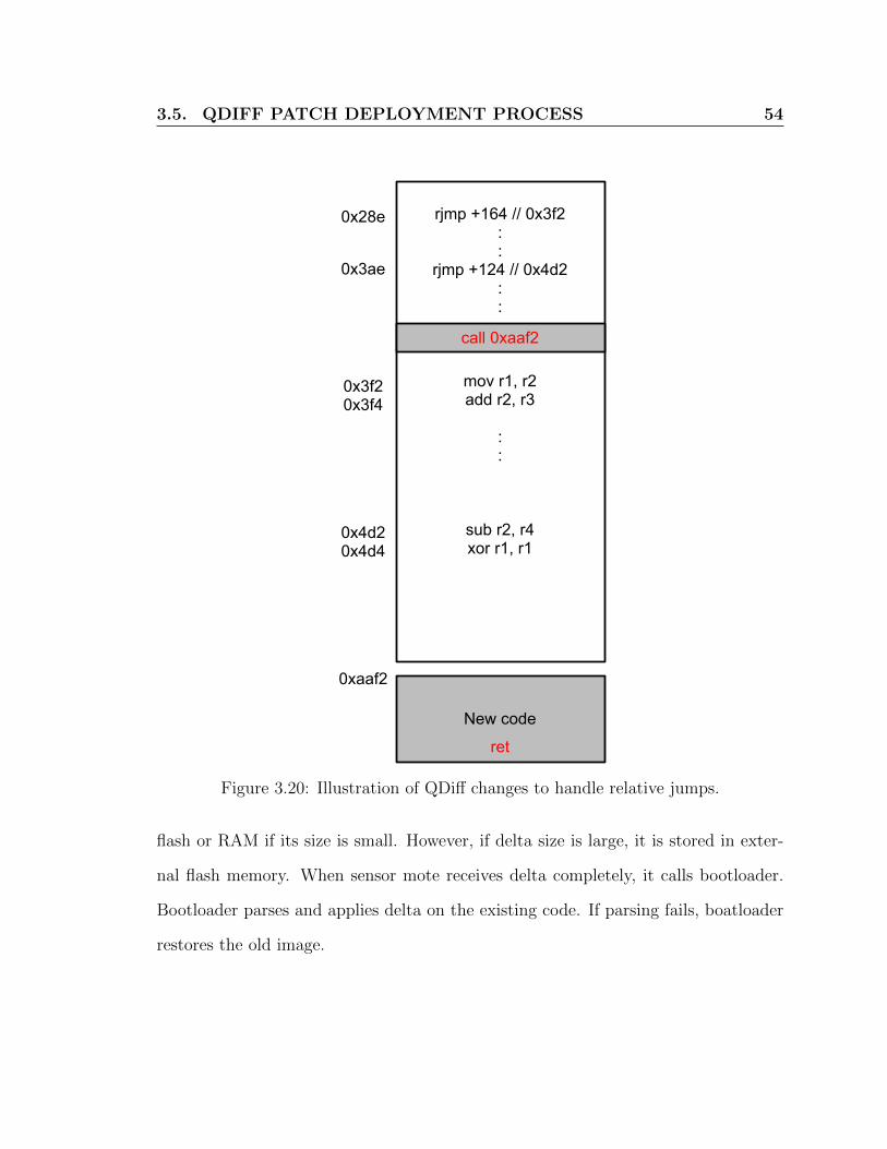
3.5. QDIFF PATCH DEPLOYMENT PROCESS 54
rjmp +164 // 0x3f2::
rjmp +124 // 0x4d2::
mov r1, r2add r2, r3
::
sub r2, r4xor r1, r1
0x28e
0x3ae
0x3f20x3f4
0x4d20x4d4
call 0xaaf2
New code
ret
0xaaf2
Figure 3.20: Illustration of QDiff changes to handle relative jumps.
flash or RAM if its size is small. However, if delta size is large, it is stored in exter-
nal flash memory. When sensor mote receives delta completely, it calls bootloader.
Bootloader parses and applies delta on the existing code. If parsing fails, boatloader
restores the old image.

3.5. QDIFF PATCH DEPLOYMENT PROCESS 55
Begin
Identify all basic blocks
Identify shifted relative jumps
Calculate delta between old and new function ignoring
shifted jump
Detect basic blocks in calculated delta
Remove and modify other instructions in delta except
basic blocks
Fix shifted relative jumps
End
All similar function touple
traversed ?
Yes
No
Step 1
Step 2
Step 3
Step 4
Step 9
Pick a similar function touple computed using clone
detection tool
Calculate delta between old and new function
considering fixed relative jumps
Modify code fragment that is padded at the end of
program by branch handling algorithm
Step 5
Step 6
Step 7
Step 8
Figure 3.21: Flowchart for fixing relative jumps.

3.5. QDIFF PATCH DEPLOYMENT PROCESS 56
Begin
Fix all branches
Fix all global variables
Fix all relative jumps
Calculate delta for
code, data and bss
section
Aggregate and
optimize all delta
Transmit delta over
wireless medium
End
Figure 3.22: Flowchart for QDiff.

57
Chapter 4
Implementation and Evaluation
In this chapter, we present the implementation details of QDiff, performance metrics,
experimental use cases and their results. For performance comparison, we considered
Zephyr [51] and Hermes [49], as they are the latest work on differential reprogramming
and show better efficiency than all previous schemes. Furthermore, both qualitative
comparison and overheads are also investigated.
4.1 Implementation details
The proposed QDiff scheme for over-the-air reprogramming of motes is implemented
using the Java language, to run on the WSNs base-station. The IRIS platform,
based on Atmega-128 microcontroller with 128KB internal flash and 4KB RAM, is
used as motes for WSNs. The motes use TinyOS as its operating system wherein
the applications are written using nesC programming language [21]. In order to
create a single OS image, i.e. monolithic image, the nesC compiler converts the
nesC code to a corresponding C code. This C file is later compiled and linked by
an architecture specific C compiler, e.g. avr-gcc for the IRIS mote. We make use

4.1. IMPLEMENTATION DETAILS 58
of the Bauhaus toolkit [55] to detect clones between programs. Bauhaus is a well-
known clone detection tool and works for various programming languages, including
C. While the Bauhaus toolkit does not work directly for assembly language, it is
still used indirectly as the compiler keeps the same identifier names for both C and
Assembly languages. We have extended the Bauhaus toolkit to enhance the clone
detections, especially to support “Type 3” clone detection. To determine clones,
various ELF sections, i.e. code, bss and data are dumped using standard binary
utilities tools, e.g. avr-objdump and avr-readelf for the IRIS mote. The implemented
QDiff code using the three sections, i.e. code, bss and data obtained for the old and
new ELF program, determines the patch which is then transmitted to the motes, over
the air. Google-guava [2] API and extended Google diff-match-patch [1] are used for
analyzing dumped ELF files and determining the patch.
The generated patch is made of series of commands as follows:
i n s e r t <newOffset><s i z e=s1><data>
d e l e t e <newOffset> <s i z e=s2>
copy <o ldOf f s e t><s i z e=s3><newOffset>
pad <newOffset><s i z e=s4>
r epeat <newOffset><s i z e=s5><numrepeat=n><addr1> . . . <addrn>
insert: This command inserts data of size s1 at newOffset memory location. This
data can either be the machine code or global variables.
delete: This command erases code and variable of size s2 from newOffset memory
location.
copy: This command copies code and variable from the old ELF to the revised
version. The address for the old and the new ELF location is specified by oldOffset
4.2. EVALUATION SCENARIOS 59
and newOffset, respectively. The data size to be copied is specified by the size s3.
This command is also used by the Hermes and Zephyr schemes to build the image
for the external memory.
pad: This command pads s4 many zero, in new image, at memory location specified
by newOffset.
repeat: This command performs consecutive copy of an instruction with same size.
The number of times and amount of data to be copied is specified by n and size s5,
respectively. This command is used by the zephyr or hermes schemes for transmitting
jump table.
The command opcode and offset address are represented using one and two bytes,
respectively. We assume address length of 24 bits which can address up to 16MB and
32MB if the address is byte aligned and word aligned, respectively. The generated
patch is fragmented into network packets and disseminated over the network using
the dissemination protocol, e.g. Stream. The received patch, depending on its size,
is stored either in the RAM (if smaller than available RAM space) or the external
memory. The external memory is used only when the patch size exceeds the RAM
space. We have implemented the bootloader using nesC language. The bootloader
parses the received patch, builds target flash memory pages and writes them back to
the internal flash memory.
4.2 Evaluation Scenarios
For experimental purposes, we use IRIS sensor mote. It uses atmega1281 microcon-
troller as a processing unit. IRIS has 8KB RAM, 128KB internal flash and 512KB
external flash memory. For debugging purpose, it provides three LEDs, LED0, LED1,

4.2. EVALUATION SCENARIOS 60
Figure 4.1: An IRIS sensor mote(LEDs are shown in circle)
LED2. Fig. 4.1 shows an IRIS mote. To cover various code modifications and to eval-
uate the performance of reprogramming protocols, we ran numerous evaluation cases.
These cases are explained in the later part of this chapter. A comprehensive evalua-
tion of a differential scheme needs to cover all the four major issues (branches, global
variables, indirect addressing, relative jumps) that are described in Chapter 3. To
this end, we introduce the following 8 cases. Case 1 only requires simple difference
calculation, however, all other cases(Case 2 - Case 8) cover these four major issues.
While the chosen code is small, in large code the same four issues will simply be
repeated multiple times.
Case 1: Blink to Blink with timer value changed

4.2. EVALUATION SCENARIOS 61
Blink is an well known application that toggles LEDs of sensor mote after a certain
time interval. This time interval is maintained through a timer module. The Blink
application considered here toggles the first LED, i.e. LED1 of mote. In the first
version of Blink, the timer value is set to 250 ms and in later version of Blink, timer
value is set to 500 ms. Fig. 4.2 illustrates code changes in case 1.
Case 2: Blink to Blink with two LED toggles in timer1
In this case, we consider Blink with three timers: Timer0, Timer1 and Timer2. Each
timer corresponds to a LED in iris mote: LED0, LED1 and LED2. Timer intervals
are set to 250 ms, 500 ms and 1000 ms for Timer0, Timer1 and Timer2, respectively.
When a particular timer fires, the corresponding LED is toggled. In modified Blink, a
single line is added in Timer0 function. Modified Timer0 function toggles both LED0
and LED1 simultaneously. Fig. 4.3 illustrates code changes in case 2.
Case 3: Blink to Blink with two toggles in each timer modified Blink
In this case, two LEDs are toggled simultaneously in each timer function. In modified
timer functions, Timer0 toggles LED0 and LED1, Timer1 toggles LED1 and LED2 ,
Timer2 toggles LED2 and LED0. Fig. 4.4 illustrates code changes in case 3.
Case 4: Blink with two toggles in each timer to further modification in
Blink
This is further update of modified blink in case 3. In this case each timer toggles
LED(s) but these toggles are reorganized i.e. Timer0 toggles LED2 and LED0, Timer1
toggles LED2 and LED1 , Timer2 toggles LED1 and LED0. Fig. 4.5 illustrates code
changes in case 4.
Case 5: RadioCountToLeds to RadioCountToLeds showing least signifi-
cant two bits

4.2. EVALUATION SCENARIOS 62
RadioCountToLeds is a widely used application for checking Active Message(AM) [62]
communication. Base-station broadcasts a counter value as AM packet, sensor mote
receives this packet and displays last three bit on its LEDs. We modify RadioCount-
ToLeds as it displays last two bits on its LEDs and value displayed in third LED is
discarded. Fig. 4.6 illustrates code changes in case 5.
Case 6: RadioCountToLeds to RadioCountToLeds showing complement of
least significant three bits
In this case, RadioCountToLeds is modified to displays 1’s complement of least sig-
nificant three bits of received counter on sensor mote LEDs. Fig. 4.7 illustrates code
changes in case 6.
Case 7: RadioCountToLeds to RadioCountToLeds showing most signifi-
cant three bits
RadioCountLeds displays least significant three bits of received 16 bit counter value
on sensor mote LEDs. In this case, RadioCountToLeds is modified to display most
significant three bits of received counter value. Fig. 4.8 illustrates code changes in
case 7.
Case 8: RadioCountToLeds to RadionCountToLeds showing even num-
bers.
In this case, RadioCountToLeds is modified to display counter bits, if it has an even
value, otherwise no change is made in sensor mote LEDs. Fig. 4.9 illustrates code
changes in case 8.

4.2. EVALUATION SCENARIOS 63
event void Boot.booted() { call Timer0.startPeriodic( 250 ); }
Blink Blink with timer value changed
event void Boot.booted() {
}
call Timer0.startPeriodic( 500 );
New code
Figure 4.2: Case 1: Timer value is changed.

4.2. EVALUATION SCENARIOS 64
event void Timer0.fired() { call Leds.led0Toggle();
} event void Timer1.fired() { call Leds.led1Toggle(); } event void Timer2.fired() { call Leds.led2Toggle(); }
event void Timer0.fired() { call Leds.led0Toggle(); } event void Timer1.fired() { call Leds.led1Toggle(); } event void Timer2.fired() { call Leds.led2Toggle(); }
Blink Blink with two toggle in Timer0
New code
call Leds.led1Toggle();
Figure 4.3: Case 2: Addition of one toggle in Timer0.

4.2. EVALUATION SCENARIOS 65
event void Timer0.fired() { call Leds.led0Toggle();
} event void Timer1.fired() { call Leds.led1Toggle();
} event void Timer2.fired() { call Leds.led2Toggle();
}
event void Timer0.fired() { call Leds.led0Toggle(); } event void Timer1.fired() { call Leds.led1Toggle(); } event void Timer2.fired() { call Leds.led2Toggle(); }
Blink Blink with two toggle in each timer
call Leds.led0Toggle();
New code
call Leds.led1Toggle();
call Leds.led2Toggle();
Figure 4.4: Case 3: Addition of one toggle in each timer i.e. Timer0 toggles LED0and LED1, Timer1 toggles LED1 and LED2 , Timer2 toggles LED2 andLED0.

4.2. EVALUATION SCENARIOS 66
event void Timer0.fired() {
} event void Timer1.fired() {
} event void Timer2.fired() { call Leds.led0Toggle(); }
event void Timer0.fired() { call Leds.led0Toggle(); call Leds.led1Toggle(); } event void Timer1.fired() { call Leds.led1Toggle(); call Leds.led2Toggle(); } event void Timer2.fired() { call Leds.led2Toggle(); call Leds.led0Toggle(); }
Blink with two toggles Blink with shuffled toggles
New code
call Leds.led2Toggle(); call Leds.led0Toggle();
call Leds.led1Toggle();
call Leds.led2Toggle(); call Leds.led1Toggle();
Figure 4.5: Case 4: Toggles are reorganized i.e. Timer0 toggles LED2 and LED0,Timer1 toggles LED2 and LED1 , Timer2 toggles LED1 and LED0.

4.2. EVALUATION SCENARIOS 67
radio_count_msg_t* rcm = (radio_count_msg_t*)payload;
if (rcm->counter & 0x1) {call Leds.led0On();
} else {
call Leds.led0Off(); } if (rcm->counter & 0x2) {
call Leds.led1On(); } else {
call Leds.led1Off(); }
radio_count_msg_t* rcm = (radio_count_msg_t*)payload;
if (rcm->counter & 0x1) {call Leds.led0On(); } else {
call Leds.led0Off(); } if (rcm->counter & 0x2) {
call Leds.led1On(); } else {
call Leds.led1Off(); }
RadioCountToLeds RadioCountToLeds showing two LSB
Deleted code
if (rcm->counter & 0x4) {call Leds.led2On();
} else {
call Leds.led2Off(); }
Figure 4.6: Case 5: RadioCountToLeds is modified to display last two bits on itsLEDs and value displayed in third LED is discarded.
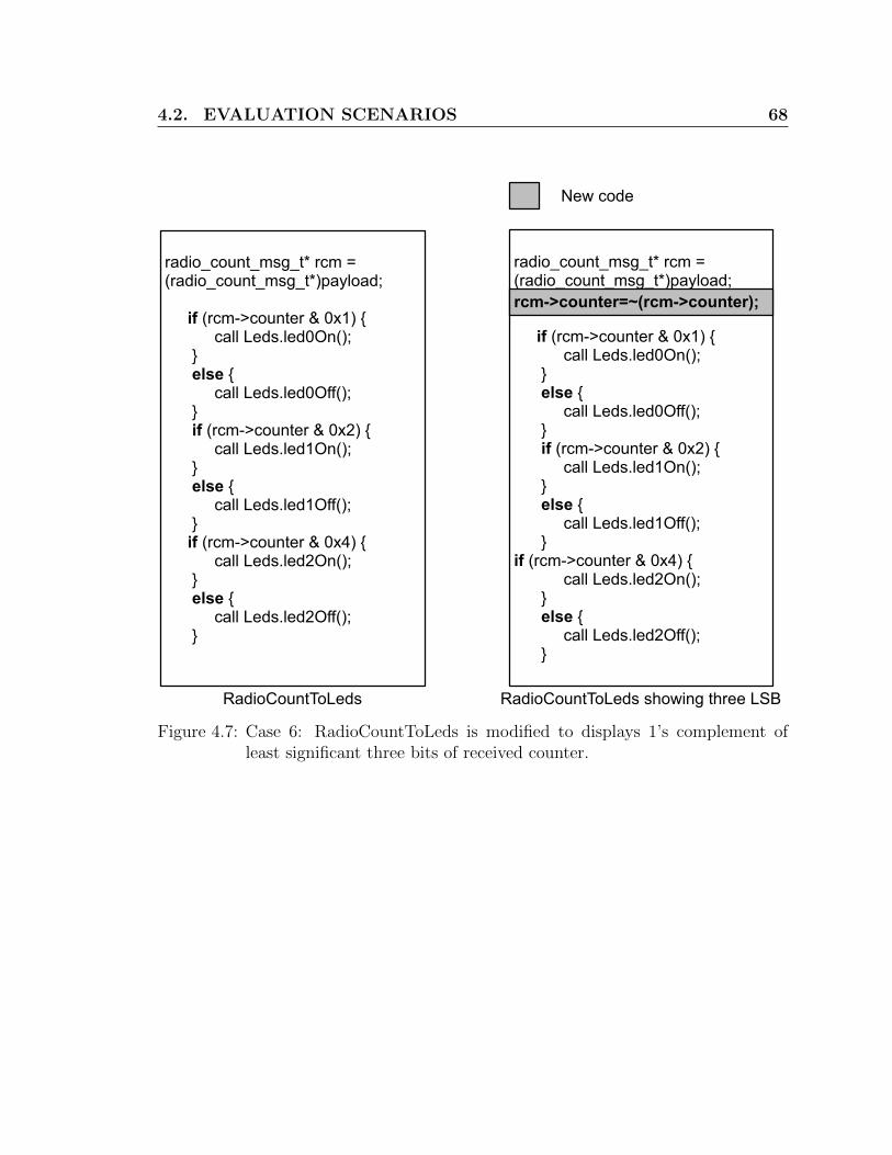
4.2. EVALUATION SCENARIOS 68
radio_count_msg_t* rcm = (radio_count_msg_t*)payload;
if (rcm->counter & 0x1) {call Leds.led0On();
} else {
call Leds.led0Off(); } if (rcm->counter & 0x2) {
call Leds.led1On(); } else {
call Leds.led1Off(); }if (rcm->counter & 0x4) {
call Leds.led2On(); } else {
call Leds.led2Off(); }
radio_count_msg_t* rcm = (radio_count_msg_t*)payload;
if (rcm->counter & 0x1) {call Leds.led0On();
} else {
call Leds.led0Off(); } if (rcm->counter & 0x2) {
call Leds.led1On(); } else {
call Leds.led1Off(); } if (rcm->counter & 0x4) {
call Leds.led2On(); } else {
call Leds.led2Off(); }
RadioCountToLeds RadioCountToLeds showing three LSB
New code
rcm->counter=~(rcm->counter);
Figure 4.7: Case 6: RadioCountToLeds is modified to displays 1’s complement ofleast significant three bits of received counter.

4.2. EVALUATION SCENARIOS 69
radio_count_msg_t* rcm = (radio_count_msg_t*)payload;
call Leds.led0On(); } else {
call Leds.led0Off(); }
call Leds.led1On(); } else {
call Leds.led1Off(); }
call Leds.led2On(); } else {
call Leds.led2Off(); }
radio_count_msg_t* rcm = (radio_count_msg_t*)payload;
if (rcm->counter & 0x1) { call Leds.led0On(); } else {
call Leds.led0Off(); } if (rcm->counter & 0x2) {
call Leds.led1On(); } else {
call Leds.led1Off(); } if (rcm->counter & 0x4) {
call Leds.led2On(); } else {
call Leds.led2Off(); }
RadioCountToLeds RadioCountToLeds showing three MSB
New code
if (rcm->counter & 0x2000) {
if (rcm->counter & 0x4000) {
if (rcm->counter & 0x8000) {
Figure 4.8: Case 7: RadioCountToLeds is modified to display most significant threebits of received counter value.
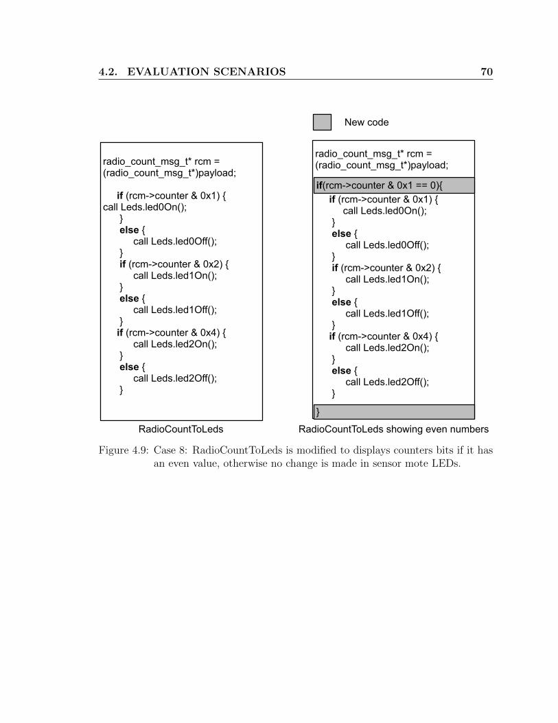
4.2. EVALUATION SCENARIOS 70
radio_count_msg_t* rcm = (radio_count_msg_t*)payload;
if (rcm->counter & 0x1) {call Leds.led0On(); } else {
call Leds.led0Off(); } if (rcm->counter & 0x2) {
call Leds.led1On(); } else {
call Leds.led1Off(); } if (rcm->counter & 0x4) {
call Leds.led2On(); } else {
call Leds.led2Off(); }
RadioCountToLeds RadioCountToLeds showing even numbers
New code
radio_count_msg_t* rcm = (radio_count_msg_t*)payload;
if (rcm->counter & 0x1) { call Leds.led0On(); } else {
call Leds.led0Off(); } if (rcm->counter & 0x2) {
call Leds.led1On(); } else {
call Leds.led1Off(); } if (rcm->counter & 0x4) {
call Leds.led2On(); } else {
call Leds.led2Off(); }
if(rcm->counter & 0x1 == 0){
}
Figure 4.9: Case 8: RadioCountToLeds is modified to displays counters bits if it hasan even value, otherwise no change is made in sensor mote LEDs.
4.3. QUANTITATIVE PERFORMANCE METRICS 71
4.3 Quantitative Performance Metrics
Energy is the most important resource in wireless sensor networks. Time required
for reprogramming sensor networks is another important factor as sensor networks
are not able to do their intended work during reprogramming period. The following
three metrics mainly affect energy and time in WSN reprogramming.
1. Patch size: Patch size refers to the file size of a generated patch. The generated
patch includes both data and commands, as explained in Section 4.1. The
size however, does not include the overhead that may be caused as the patch
size is fragmented into smaller network packets. Patch size is an important
performance metric as smaller patches imply lesser data transmission in WSNs,
hence lower energy consumptions. Furthermore, small patch size also implies
lesser reprogramming time for each mote.
2. Internal flash writing: Internal flash writing refers to the number of flash
memory pages required to be rewritten upon receiving a patch. The internal
flash size also includes the overhead of using external flash to build (or modify)
the newly received image. However, we do not include the overhead to load
the reprogramming protocol from the external storage into internal flash. En-
ergy consumption of flash memory writing is similar to wireless transmissions.
Therefore, reducing internal flash writing reduces the energy consumption of
mote, hence allowing more of the motes reprogramming while maintaining the
network lifetime.
3. External flash usage: External flash usage refers to the amount of external
flash memory required for storing patch script and building new image from

4.4. PERFORMANCE EVALUATION 72
patch script. External flash, if present, for certain applications is mainly used
for various network functions, e.g. storing sensing and debugging information,
logging network events etc. However, it is not a mandatory requirement for
other applications, e.g. real-time pressure sensing in home automation. More-
over, accessing the external flash memory for either read or write, performed
via SPI bus, is both slow and power hungry. Therefore, reducing the amount of
external flash, or ideally eliminate the need of it by the reprogramming scheme
is of great importance for the WSNs.
4.4 Performance Evaluation
In this section, we quantitatively and qualitatively analyze Stream, Hermes, and QDiff
reprogramming schemes for various evaluation scenarios (Section 4.2) using various
performance metrics (Section 4.3).
4.4.1 Patch size
Patch size is the file size of a generated patch. The lower the size, the better the
scheme is. Patch sizes for all of the evaluation scenarios, for Stream, Hermes and
QDiff, are shown in Fig. 4.10. QDiff outperforms Stream and Hermes up to 250
and 12 times, respectively, for all of the scenarios considered. The highest relative
improvement, between QDiff and Hermes, is observed for “Case 8”. In this case, due
to compiler optimizations, the function order has been changed. This is not detected
by the Hermes scheme. QDiff, on the other hand, using the clone detection technique
is able to detect this structural change, therefore is much more efficient.
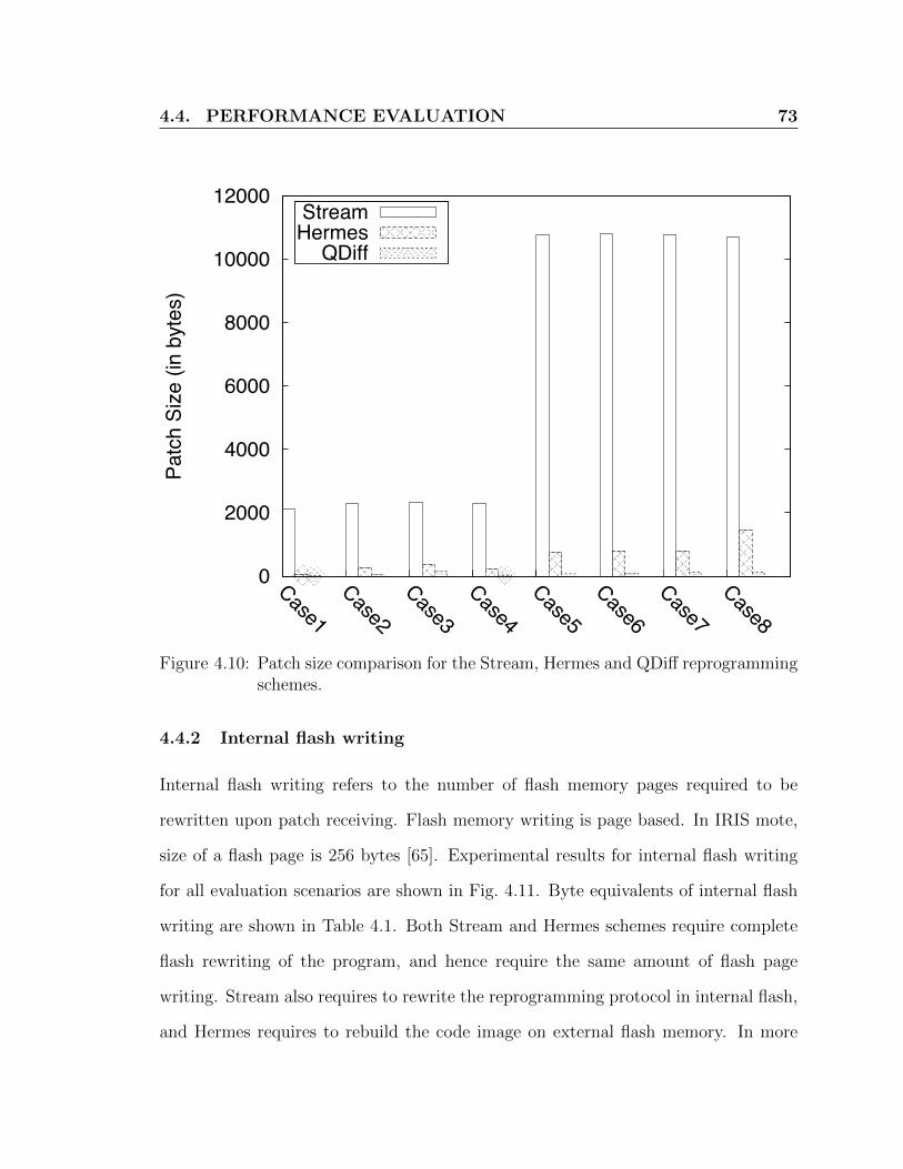
4.4. PERFORMANCE EVALUATION 73
0
2000
4000
6000
8000
10000
12000
Case1Case2
Case3Case4
Case5Case6
Case7Case8
Patc
h Si
ze (i
n by
tes)
StreamHermes
QDiff
Figure 4.10: Patch size comparison for the Stream, Hermes and QDiff reprogrammingschemes.
4.4.2 Internal flash writing
Internal flash writing refers to the number of flash memory pages required to be
rewritten upon patch receiving. Flash memory writing is page based. In IRIS mote,
size of a flash page is 256 bytes [65]. Experimental results for internal flash writing
for all evaluation scenarios are shown in Fig. 4.11. Byte equivalents of internal flash
writing are shown in Table 4.1. Both Stream and Hermes schemes require complete
flash rewriting of the program, and hence require the same amount of flash page
writing. Stream also requires to rewrite the reprogramming protocol in internal flash,
and Hermes requires to rebuild the code image on external flash memory. In more

4.4. PERFORMANCE EVALUATION 74
0
5
10
15
20
25
30
35
40
45
Case1Case2
Case3Case4
Case5Case6
Case7Case8
Inte
rnal
Fla
sh (i
n Pa
ges)
StreamHermes
QDiff
Figure 4.11: Internal flash writing comparison for the Stream, Hermes and QDiffreprogramming schemes.
complex real-life scenarios, these flash writings could be significantly higher. As shown
in Table 4.1, the proposed QDiff scheme outperforms both Stream and Hermes, by
a factor of 21 times. Furthermore, the QDiff scheme, unlike other schemes, is not
affected by the complexity of the use case. For instance, the frequency of internal
flash writings for both Stream and Hermes jump five times, between Case 4 and Case
5. This is because, QDiff only writes modified flash pages, whereas both Stream and
Hermes rewrite the whole program flash every time.

4.4. PERFORMANCE EVALUATION 75
Stream Hermes QDiffCase 1 2304 2304 256Case 2 2304 2304 512Case 3 2560 2560 512Case 4 2560 2560 512Case 5 11008 11008 512Case 6 11008 11008 512Case 7 11008 11008 512Case 8 10752 10752 512
Table 4.1: Internal flash memory bytes comparison for the Stream, Hermes and QDiff
4.4.3 External flash usage
External flash usage refers to the amount of external flash memory required for storing
patch script and building new image from that script. In the Hermes scheme, the
bootloader builds the new image using the patch script on external flash. Similarly,
the Stream scheme also stores both the reprogramming protocol and the patch file in
the external flash. Experimental results for external flash memory usages(in pages)
and their byte equivalents are shown in Fig. 4.12 and Table 4.2, respectively. Results
do not include the flash memory required for storing the golden image. Both Stream
and Hermes require large volume of external memory. Hermes requires more external
flash as it needs to store the patch script, as well as build and store new image.
However, the QDiff scheme does not require any external memory as it can build the
new image using RAM. This results in significant lower energy consumption and less
reprogramming time for the motes.
4.4.4 System Restart
Existing reprogramming schemes require the mote to be restarted. This restart is
essential as these schemes perform complete code flash rewriting, even for the simplest
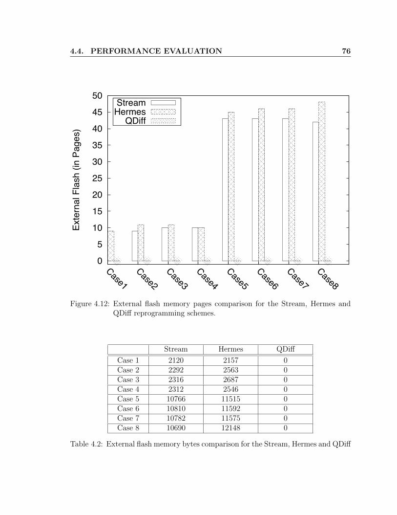
4.4. PERFORMANCE EVALUATION 76
0
5
10
15
20
25
30
35
40
45
50
Case1Case2
Case3Case4
Case5Case6
Case7Case8
Exte
rnal
Fla
sh (i
n Pa
ges)
StreamHermes
QDiff
Figure 4.12: External flash memory pages comparison for the Stream, Hermes andQDiff reprogramming schemes.
Stream Hermes QDiff
Case 1 2120 2157 0Case 2 2292 2563 0Case 3 2316 2687 0Case 4 2312 2546 0Case 5 10766 11515 0Case 6 10810 11592 0Case 7 10782 11575 0Case 8 10690 12148 0
Table 4.2: External flash memory bytes comparison for the Stream, Hermes and QDiff
4.4. PERFORMANCE EVALUATION 77
case. Restarting of the WSN mote is energy inefficient and results in overall network
instability and functional failure. For instance, in a recent deployment on Reventador
Volcano, reboots led to 3-day network outage, reducing mean node uptime from >90%
to 69% [14, 64]. An exception is the Elon scheme. However, Elon only works for
certain WSNs platform, e.g. TelosB. Our proposed QDiff scheme does not require
mote restart and is independent of the WSNs platform and its operating system.
4.4.5 Code Overheads
Code size: A reprogramming scheme usually inserts new instructions, slop regions,
jump tables and other translation schemes, which result into large program sizes.
Maintaining lower code size increment is important as the mote has a limited available
memory. The proposed QDiff reprogramming scheme also introduces overhead as
additional jump calls. However, such overhead is insignificant as each of these jump
instruction, and subsequent return instruction, take only 6 bytes. Furthermore, as the
call-return instructions are only added for only few functions, the overall increment
is, on average, within 3% of the total code memory.
Fragmentation: After several reprogramming the program code residing on the
internal flash memory, due to the added call-return by the QDiff scheme, may get
fragmented. To overcome this issue the base-station keeps track and instructs motes
to rebuild the new program image if fragmentation reaches a certain threshold. In
the new code, the code blocks addressed by the call-return functions are replaced to
the callee locations. The defragmentation process is not energy intensive since the
base-station only sends the fragmented call-jump code over the network.

4.4. PERFORMANCE EVALUATION 78
Patch External Flash Systemsize flash rewrite Heterogeneity Restart
Deluge [26] Huge Yes Yes Multiple YesRsync [60] Medium Yes Yes Multiple YesZephyr [51] Low Yes Yes Multiple YesHermes [49] Low Yes Yes Multiple YesElon [14] Medium Yes Yes Single NoQDiff Very low No No All No
Table 4.3: Qualitative comparison of various reprogramming schemes
4.4.6 Heterogeneity
Many different hardware platforms and operating systems are available for WSNs,
with diverse specifications. All of the existing schemes, by design, can only support a
subset of these platforms. For instance, some of the reprogramming schemes [14, 48]
are specific to the TinyOS operating system, several others [15,16] are specific to the
Contiki operating system whereas some [14] are tied to a particular mote platform.
However, the proposed QDiff is independent of the mote platform and its operating
system.
An overall qualitative comparison of Deluge, Rsync, Zephyr, Hermes, Elon and
QDiff is shown in Table 4.3.

79
Chapter 5
Conclusion
Wireless reprogramming is an important requirement for managing large scale wire-
less sensor networks. Existing reprogramming schemes transmit large amounts of
information over the network, rewrite the whole internal flash memory and require
large amount of external flash memory. Radio transmission and flash memory writing
are two of the most energy- and time-intensive operations in wireless sensor networks.
This thesis describes, QDiff, a new reprogramming scheme, which reduces the amount
of information to be transmitted, reduces internal flash memory writing and elimi-
nates necessity of external memory without modifying the compiler. Experiments
show that QDiff reduces information size by a factor of 11 times and internal flash
memory writing by a factor of 20 times than existing reprogramming schemes. QDiff
achieves this efficiency by exploiting the strength of clone detection mechanisms and
re-arranging global variables in the final executable file. To the best of our knowl-
edge, QDiff is the first scheme utilizing clone detection in high level language and
exploits clone information in machine language for efficient reprogramming in sensor
networks. Furthermore, QDiff works on various hardware and software platforms to
support the application-specific nature of sensor networks.

80
Our future work on QDiff focuses on fault-tolerance support while using QDiff as
a reprogramming scheme. Updating software using faulty patch might result crash
of sensor node forever. It is an important issue as senor-nodes run without human
interaction. We are currently looking for a way that is compatible with QDiff, as well
as able to provide fault-tolerance support by recovering software from golden image
after system crash without rebooting sensor node.

BIBLIOGRAPHY 81
Bibliography
[1] Google-diff-match-patch-diff, match and patch libraries for plain text, available:http://code.google.com/p/google-diff-match-patch/, last modified: October 12,2011.
[2] Guava-libraries-guava: Google core libraries for java 1.5+, available:http://code.google.com/p/guava-libraries/, last modified: October 10, 2011.
[3] S. Bhatti, J. Carlson, H. Dai, J. Deng, J. Rose, A. Sheth, B. Shucker, C. Gru-enwald, A. Torgerson, and R. Han. MANTIS OS: An embedded multithreadedoperating system for wireless micro sensor platforms. Mobile Networks and Ap-plications, 10(4):563–579, 2005.
[4] Tatiana Bokareva, Wen Hu, Salil Kanhere, Branko Ristic, Travis Bessell, MarkRutten, and Sanjay Jha. Wireless sensor networks for battlefield surveillance. InProceedings of the Land Warfare Conference, 2006.
[5] Niels Brouwers, Peter Corke, and Koen Langendoen. A java compatible virtualmachine for wireless sensor nodes. In Proceedings of the 6th ACM Conference onEmbedded Network Sensor Systems (SenSys), pages 369–370, 2008.
[6] Qing Cao, T. Abdelzaher, J. Stankovic, and Tian He. The liteos operating sys-tem: Towards unix-like abstractions for wireless sensor networks. In ProceedingsInternational Conference Information Processing in Sensor Networks (IPSN),pages 233–244, 2008.
[7] Hojung Cha, Sukwon Choi, Inuk Jung, Hyoseung Kim, Hyojeong Shin, JaehyunYoo, and Chanmin Yoon. Retos: Resilient, expandable, and threaded operatingsystem for wireless sensor networks. In Proceedings 6th International SymposiumInformation Processing in Sensor Networks (IPSN), pages 148–157, 2007.
[8] S.L. Chen, H.Y. Lee, C.A. Chen, C.C. Lin, and C.H. Luo. A wireless body sen-sor network system for healthcare monitoring application. In IEEE BiomedicalCircuits and Systems Conference ( BIOCAS), pages 243–246, 2007.
BIBLIOGRAPHY 82
[9] J.I. Choi, J.W. Lee, M. Wachs, and P. Levis. Opening the sensornet black box.ACM SIGBED Review, 4(3):13–18, 2007.
[10] A.N. Das, D.O. Popa, P.M. Ballal, and F.L. Lewis. Data-logging and supervisorycontrol in wireless sensor networks. International Journal of Sensor Networks,6(1):13–27, 2009.
[11] Y. Diao, D. Ganesan, G. Mathur, and P. Shenoy. Rethinking data manage-ment for storage-centric sensor networks. In Proceedings of the Third BiennialConference on Innovative Data Systems Research (CIDR), 2007.
[12] Soledad Escolar Dıaz, Florin Isaila, Alejandro Calderon Mateos, Luis MiguelSanchez Garcıa, and David E. Singh. Senfis: a sensor node file system for in-creasing the scalability and reliability of wireless sensor networks applications.J. Supercomput., 51(1):76–93, 2010.
[13] W. Dong, Y. Liu, C. Chen, J. Bu, and C. Huang. R2: Incremental reprogrammingusing relocatable code in networked embedded systems. In Proceedings IEEEINFOCOM, pages 376–380, 2011.
[14] W. Dong, Y. Liu, X. Wu, L. Gu, and C. Chen. Elon: enabling efficient andlong-term reprogramming for wireless sensor networks. In Proceedings of theACM SIGMETRICS International Conference on Measurement and Modeling ofComputer Systems, pages 49–60, 2010.
[15] Wei Dong, Chun Chen, Xue Liu, Jiajun Bu, and Yunhao Liu. Dynamic linkingand loading in networked embedded systems. In Proceedings IEEE 6th Inter-national Conference Mobile Adhoc and Sensor Systems (MASS), pages 554–562,2009.
[16] Adam Dunkels, Niclas Finne, Joakim Eriksson, and Thiemo Voigt. Run-timedynamic linking for reprogramming wireless sensor networks. In Proceedings ofthe Fourth ACM Conference on Embedded Networked Sensor Systems (SenSys),2006.
[17] Adam Dunkels, Niclas Finne, Joakim Eriksson, and Thiemo Voigt. Reprogram-ming wireless sensor networks with run-time dynamic linking in contiki. InProceedings of Real-Time in Sweden, 2007.
[18] Adam Dunkels, Bjrn Grnvall, and Thiemo Voigt. Contiki - a lightweight andflexible operating system for tiny networked sensors. In Proceedings of the FirstIEEE Workshop on Embedded Networked Sensors (Emnets-I), 2004.

BIBLIOGRAPHY 83
[19] A. Eswaran, A. Rowe, and R. Rajkumar. Nano-rk: an energy-aware resource-centric rtos for sensor networks. In Proceedings 26th IEEE International Real-Time Systems Symp (RTSS 2005), 2005.
[20] E. Gal and S. Toledo. A transactional flash file system for microcontrollers. InProceedings of the annual Conference on USENIX Annual Technical Conference,pages 7–7, 2005.
[21] David Gay, Philip Levis, Robert von Behren, Matt Welsh, Eric Brewer, andDavid Culler. The nesc language: A holistic approach to networked embeddedsystems. In Proceedings of the ACM SIGPLAN 2003 Conference on ProgrammingLanguage Design and Implementation (PLDI), pages 1–11, 2003.
[22] N. Gershenfeld, R. Krikorian, and D. Cohen. The internet of things. ScientificAmerican, 291(4):76–81, 2004.
[23] Chih-Chieh Han, Ram Kumar, Roy Shea, Eddie Kohler, and Mani Srivastava.A dynamic operating system for sensor nodes. In Proceedings of the 3rd Inter-national Conference on Mobile systems, Applications, and Services (MobiSys),pages 163–176, 2005.
[24] T. He, S. Krishnamurthy, J.A. Stankovic, T. Abdelzaher, L. Luo, R. Stoleru,T. Yan, L. Gu, J. Hui, and B. Krogh. Energy-efficient surveillance system usingwireless sensor networks. In Proceedings of the 2nd International Conference onMobile systems, Applications, and Services (MobiSys), pages 270–283, 2004.
[25] T.J. Hofmeijer, S.O. Dulman, P.G. Jansen, and P.J.M. Havinga. Ambientrt - realtime system software support for data centric sensor networks. In Proceedings ofthe Intelligent Sensors, Sensor Networks and Information Processing Conference,pages 61 – 66, 2004.
[26] Jonathan W. Hui and David Culler. The dynamic behavior of a data dissemina-tion protocol for network programming at scale. In Proceedings of the 2nd In-ternational Conference on Embedded networked Sensor systems (SenSys), pages81–94, 2004.
[27] J. Jeong, S. Kim, and A. Broad. network reprogramming, tinyos documenta-tion, available: http://www.tinyos.net/tinyos-1.x/doc/Xnp.pdf, last modified:September 10, 2003.
[28] Jaein Jeong and D. Culler. Incremental network programming for wireless sen-sors. In Proceedings First Annual IEEE Communications Society ConferenceSensor and Ad Hoc Communications and Networks (SECON), pages 25–33, 2004.

BIBLIOGRAPHY 84
[29] H.F. Jiang, Y.Q. Zhen, and Y. Fu. Design of gateway of wireless sensor networkin coal mine. Jisuanji Gongcheng/ Computer Engineering, 35(3):112–114, 2009.
[30] E. Jovanov, A. Milenkovic, C. Otto, and P. de Groen. A wireless body area net-work of intelligent motion sensors for computer assisted physical rehabilitation.Journal of NeuroEngineering and rehabilitation, 2(1):6, 2005.
[31] Philo Juang, Hidekazu Oki, Yong Wang, Margaret Martonosi, Li Shiuan Peh,and Daniel Rubenstein. Energy-efficient computing for wildlife tracking: designtradeoffs and early experiences with zebranet. SIGPLAN Not., 37:96–107, 2002.
[32] H. Karl and A. Willig. Protocols and architectures for wireless sensor networks.Wiley-Interscience, 2007.
[33] Sukun Kim, Shamim Pakzad, David Culler, James Demmel, Gregory Fenves,Steve Glaser, and Martin Turon. Wireless sensor networks for structural healthmonitoring. In Proceedings of the 4th International Conference on Embeddednetworked Sensor systems (SenSys), pages 427–428, 2006.
[34] J. Koshy and R. Pandey. Remote incremental linking for energy-efficient repro-gramming of sensor networks. In Proceeedings of the Second European Workshopon Wireless Sensor Networks, pages 354 – 365, 2005.
[35] Joel Koshy and Raju Pandey. Vmstar: synthesizing scalable runtime environ-ments for sensor networks. In Proceedings of the 3rd International Conferenceon Embedded networked Sensor systems (SenSys), pages 243–254, 2005.
[36] S. Kroc and V. Delic. Personal wireless sensor network for mobile health caremonitoring. In 6th International Conference on Telecommunications in ModernSatellite, Cable and Broadcasting Service, volume 2, pages 471–474, 2003.
[37] J.R. Levine. Linkers and loaders. Morgan Kaufmann Pub, 2000.
[38] P. Levis, D. Gay, V. Handziski, J.H. Hauer, B. Greenstein, M. Turon, J. Hui,K. Klues, C. Sharp, R. Szewczyk, et al. T2: A second generation os for embeddedsensor networks. Technical report, Technical Report TKN-05-007, Telecommu-nication Networks Group, Technische Universitat Berlin, 2005.
[39] P. Levis, N. Patel, D. Culler, and S. Shenker. Trickle: A self-regulating algorithmfor code propagation and maintenance in wireless sensor networks. In Proceed-ings of the First USENIX/ACM Symposium on Networked Systems Design andImplementation (NSDI), volume 246, 2004.

BIBLIOGRAPHY 85
[40] Philip Levis and David Culler. Mate: a tiny virtual machine for sensor networks.In ASPLOS-X: Proceedings of the 10th International Conference on Architecturalsupport for programming languages and operating systems, pages 85–95, 2002.
[41] M. Li and Y. Liu. Underground coal mine monitoring with wireless sensor net-works. ACM Transactions on Sensor Networks (TOSN), 5(2):10, 2009.
[42] Y. Liu, G. Zhou, J. Zhao, G. Dai, X.Y. Li, M. Gu, H. Ma, L. Mo, Y. He,J. Wang, et al. Long-term large-scale sensing in the forest: recent advances andfuture directions of greenorbs. Frontiers of Computer Science in China, pages1–5, 2010.
[43] K.S. Low, W.N.N. Win, and M.J. Er. Wireless sensor networks for industrial en-vironments. In International Conference on Intelligent Agents, Web Technologiesand Internet Commerce, International Conference on Computational Intelligencefor Modelling, Control and Automation, volume 2, pages 271–276, 2005.
[44] Alan Mainwaring, David Culler, Joseph Polastre, Robert Szewczyk, and JohnAnderson. Wireless sensor networks for habitat monitoring. In Proceedings of the1st ACM International Workshop on Wireless Sensor Networks and Applications(WSNA), pages 88–97, 2002.
[45] Gaurav Mathur, Peter Desnoyers, Paul Chukiu, Deepak Ganesan, and PrashantShenoy. Ultra-low power data storage for sensor networks. ACM Trans. Sen.Netw., 5(4):1–34, 2009.
[46] Sam Michiels, Wouter Horre, Wouter Joosen, and Pierre Verbaeten. Davim: adynamically adaptable virtual machine for sensor networks. In Proceedings of theInternational Workshop on Middleware for Sensor Networks (MidSens), pages7–12, 2006.
[47] Rene Muller, Gustavo Alonso, and Donald Kossmann. A virtual machine forsensor networks. In Proceedings of the 2nd ACM SIGOPS/EuroSys EuropeanConference on Computer Systems (EuroSys), pages 145–158, 2007.
[48] W. Munawar, M.H. Alizai, O. Landsiedel, and K. Wehrle. Dynamic TinyOS:Modular and Transparent Incremental Code-Updates for sensor networks. Pro-ceedings of the IEEE ICC, 2010.
[49] R. K. Panta and S. Bagchi. Hermes: Fast and energy efficient incremental codeupdates for wireless sensor networks. In Proceedings IEEE INFOCOM, pages639–647, 2009.

BIBLIOGRAPHY 86
[50] Rajesh Krishna Panta, Saurabh Bagchi, and Issa M. Khalil. Efficient wirelessreprogramming through reduced bandwidth usage and opportunistic sleeping.Ad Hoc Networks, 7(1):42 – 62, 2009.
[51] R.K. Panta, S. Bagchi, and S.P. Midkiff. Zephyr: Efficient incremental repro-gramming of sensor nodes using function call indirections and difference compu-tation. In Proceedings of USENIX Annual Technical Conference, 2009.
[52] S. Patel and Y.N. Gopalan. Transaction-safe FAT file system improvements,2008. US Patent 7,363,540.
[53] J. Polastre, R. Szewczyk, and D. Culler. Telos: enabling ultra-low power wire-less research. In Fourth International Symposium on Information Processing inSensor Networks, (IPSN), pages 364 – 369, 2005.
[54] C.S. Raghavendra, K.M. Sivalingam, and T.F. Znati. Wireless sensor networks.Springer, 2004.
[55] A. Raza, G. Vogel, and E. Plodereder. Bauhaus–a tool suite for program analysisand reverse engineering. Reliable Software Technologies–Ada-Europe 2006, pages71–82, 2006.
[56] Adi Mallikarjuna V. Reddy, A.V.U. Phani Kumar, D. Janakiram, and G. AshokKumar. Wireless sensor network operating systems; a survey. International J.Sen. Netw., 5(4):236–255, 2009.
[57] Niels Reijers and Koen Langendoen. Efficient code distribution in wireless sensornetworks. In Proceedings of the 2nd ACM International Conference on WirelessSensor Networks and Applications (WSNA), pages 60–67, 2003.
[58] B. Saballus, J. Eickhold, and T. Fuhrmann. Towards a distributed Java vm insensor networks using scalable source routing. Fachgesprach Sensornetzwerke,pages 47–50, 2007.
[59] A.S. Tanenbaum and A. Tannenbaum. Modern operating systems, 2nd edition.Prentice Hall, 2001.
[60] A. Tridgell and P. Mackeras. The rsync algorithm. technical report available:http://samba.anu.edu.au/rsync/tech report/tech report.html. Technical report,Australian National University, 1998.
[61] N. Tsiftes, A. Dunkels, and T. Voigt. Efficient sensor network reprogrammingthrough compression of executable modules. In 5th Annual IEEE Communi-cations Society Conference on Sensor, Mesh and Ad Hoc Communications andNetworks (SECON), pages 359 –367, 2008.

BIBLIOGRAPHY 87
[62] Thorsten von Eicken, David E. Culler, Seth Copen Goldstein, and Klaus ErikSchauser. Active messages: a mechanism for integrated communication andcomputation. SIGARCH Comput. Archit. News, 20:256–266, 1992.
[63] X. Wang, X. Zhao, Z. Liang, and M. Tan. Deploying a wireless sensor networkon the coal mines. In IEEE International Conference on Networking, Sensingand Control, pages 324–328, 2007.
[64] Geoffrey Werner-Allen, Konrad Lorincz, Matt Welsh, Omar Marcillo, Jeff John-son, Mario Ruiz, and Jonathan Lees. Deploying a wireless sensor network on anactive volcano. IEEE Internet Computing, 10:18–25, 2006.
[65] Xbow. Iris datasheet. available: http://www.xbow.com/products/ prod-uct pdf files/ wireless pdf/ iris datasheet.pdf.
[66] Ning Xu, Sumit Rangwala, Krishna Kant Chintalapudi, Deepak Ganesan, AlanBroad, Ramesh Govindan, and Deborah Estrin. A wireless sensor network forstructural monitoring. In Proceedings of the 2nd International Conference onEmbedded networked Sensor systems (SenSys), pages 13–24, 2004.
[67] J. Yannakopoulos and A. Bilas. Cormos: a communication-oriented runtimesystem for sensor networks. In Proceeedings of the Second European Workshopon Wireless Sensor Networks, pages 342 – 353, 2005.
[68] L. Zheng. Zigbee wireless sensor network in industrial applications. In Interna-tional Joint Conference SICE-ICASE., pages 1067–1070, 2006.