efficient indoor voc air cleaning with1 energy efficient indoor voc air cleaning with activated...
TRANSCRIPT

1
Energy Efficient Indoor VOC Air Cleaning with Activated Carbon Fiber (ACF) Filters
Meera A. Sidheswaran1, Hugo Destaillats1,2,, Douglas P. Sullivan1, Sebastian Cohn1, and William J. Fisk1
1Environmental Energy Technologies Division Indoor Environment Department Lawrence Berkeley National Laboratory 2Arizona State University School of Sustainable Engineering and the Built Environment Phoenix, AZ
April 2011 This work was supported by the Assistant Secretary for Energy Efficiency and Renewable Energy, Building Technologies Program of the U.S. Department of Energy under Contract No. DE‐AC02‐05CH11231. LBNL‐5176E

2
Energy Efficient Indoor VOC Air Cleaning with Activated Carbon Fiber (ACF) Filters
Meera A. Sidheswaran1, Hugo Destaillats1,2,*, Douglas P. Sullivan1,
Sebastian Cohn1, and William J. Fisk1
1. Lawrence Berkeley National Laboratory, Indoor Environment Department 2. Arizona State University, School of Sustainable Engineering and the Built Environment * to whom correspondence should be addressed: [email protected]
Abstract
This study explores the potential environmental and energy benefits of using activated carbon
fiber (ACF) filters for air cleaning in HVAC systems. The parallel aims for the air cleaning
system were to enable reduced indoor exposures to volatile organic compounds (VOCs) and to
simultaneously allow reduced rates and energy consumption for outdoor-air ventilation. We
evaluated the use of ACF media to adsorb VOCs from indoor air during repeated simulated 12-
hour to 24-hour periods of occupancy. In a cyclic regeneration process, VOCs were desorbed
from the ACF media and vented outdoors to enable the next cycle of air cleaning. The VOC
removal efficiency of the ACF media was measured using a 9.5-cm2 ACF specimen exposed to a
mixture of VOCs that included toluene, benzene, o-xylene, 1-butanol, limonene, undecane and
formaldehyde at 29 oC and 30% relative humidity. The concentrations of these model pollutants
upstream of the ACF media were in the range 20 to 30 ppb, to simulate realistic conditions.
Velocities through the ACF media were typical of those in normal particle filter systems (~0.5 m
s-1). Initial tests were conducted to develop a modified multi-component Freundlich isotherm and
estimate the maximum adsorption capacity of the media, which was determined to be 90 mg
VOC per gram of ACF. Three different ACF regeneration methods were explored using
relatively cleaner outdoor air under ambient conditions, with this air humidified, and with the
filter heated. It was found that heating the ACF media to ~ 150 oC by circulation of a DC current
through the fibers for a short period (15 minutes) yielded the best VOC removal results, allowing
for subsequent consistent removal efficiencies of 70 – 80% for most VOCs. Regeneration with
3
unheated outdoor air was also effective and used less energy (subsequent removal efficiency was
50 – 60% for most VOCs). ACF did not perform as well in eliminating formaldehyde, for which
a maximum removal of 25-30% was achieved with heated regeneration. A mass balance model
indicated that the combination of ACF air cleaning and a 50% reduction in ventilation will
decrease indoor concentrations of VOCs by 60% to 80% and reduce formaldehyde
concentrations by 12% to 40%. Energy modeling indicated the potential to reduce the energy
required for heating and cooling of ventilation air by 35% to almost 50%.

4
1 Introduction
Ventilation with outdoor air is required to maintain acceptable concentrations of indoor-
generated air pollutants. Analyses of recent modeling indicate that approximately 10% of the
energy consumed in the U.S. commercial building stock is used to condition ventilation air
(Benne et al. 2009; Griffith et al 2008) provided mechanically and through air leakage. Energy-
saving reductions in ventilation rates may be feasible if air cleaning systems can compensate for
the diminished rate of pollutant removal by ventilation. For a ~50% reduction in outdoor air
ventilation, a volatile organic compound (VOC) removal efficiency of 15 – 20% would be
required in the supply airstream of a commercial building heating, ventilating, and air
conditioning (HVAC) system that contains 15% to 20% outdoor air and 80% to 85% re-
circulated indoor air (Hodgson et al, 2007).
In most commercial buildings, there are few indoor sources of inorganic gaseous
pollutants, and the primary indoor-generated airborne pollutants affected by ventilation are
particles and VOCs. The existing particle filters in HVAC systems of buildings remove indoor
generated particles using far less energy than ventilation. To complement particle filtration,
effective and energy efficient air cleaning methods are needed for VOCs. Recent studies have
tested granular activated carbon (GAC) filters for VOC removal in non-industrial buildings and
have proposed test methods to evaluate the performance of such air cleaning technologies for
reduction in ventilation (Bastani et al., 2010; Haghighat et al., 2008). Similar to GAC, activated
carbon fiber filters (ACF) can be implemented to efficiently remove VOCs from indoor air.
Activated carbon fiber (ACF) filters are prepared from fabric precursors and have a very high
surface area (specific BET surface area typically higher than 1000 m2 g-1) (Das et al, 2004) and
low pressure drop, which make them ideal candidates for use as VOC filters in HVAC systems.
Recent studies show that ACF filters are very good VOC adsorbents, showing better
performance than granular activated carbon, zeolites and silica gel under identical operation
conditions (Das et al, 2004). These filters have a long life time with consistent VOC removal if
regenerated periodically. The regeneration process drives previously adsorbed VOCs off the
ACF media and exhausts those VOCs outside the building. Liu (1992) found that desorption of
5
VOCs is very rapid in ACF, as opposed to granular carbon media, and that 90 to 95% of the
toluene adsorbed on an ACF system could be successfully desorbed with ambient air in less than
two hours, using as regeneration air flow rate a 20% of the air flow rate during air cleaning,
temperatures of 7.2 –18.3 oC, and relative humidity of 50 to 80%.
In other studies, effective regeneration of the ACF filter was achieved by direct current
(DC) electrical heating (Das et al, 2004; Subrenat and LeCloirec, 2004). Yao et al (2009a,
2009b) suggested that short periods of DC electrical heating of the carbon fibers to 150 or 200 oC
is a promising option for periodically regenerating ACF. During the heating period, air flows
through the ACF at a lower flow rate and is exhausted outdoors. As an alternative to DC heating
of the ACF media, regeneration might be accomplished by passing heated air through the ACF
media. However, it is essential to optimize parameters such as duration and frequency of
regeneration cycles, the air flow rate and temperature. The ACF system must be energy efficient
compared to the traditional ventilation process while still providing sufficient regeneration to
enable effective air cleaning during periods of building occupancy.
Although there has been prior research on VOC removal using activated carbon fiber
media and media regeneration, these studies were limited to high concentrations of VOCs (parts
per million) and were generally targeted towards single compounds. However, to allow a
reduction in ventilation rates, an air cleaning system needs to be effective in removing a broad
spectrum of VOCs that are present simultaneously in the indoor air at low ppb-level
concentrations. In this study we have investigated ACF performance in those realistic conditions,
by evaluating the use of such ACF systems to remove a mixture of VOCs from indoor air during
work hours, with periodic, e.g., nightly, in-situ regeneration of the carbon fiber media.
Regeneration would allow the filter to provide effective VOC air cleaning during the subsequent
period of occupancy. We characterized the maximum ACF adsorption capacity and evaluated
VOC removal performance for a range of indoor VOCs, with realistic indoor concentrations,
over periods that included multiple adsorption-regeneration cycles. Two different regeneration
techniques were evaluated to optimize this technology, using heated and unheated outdoor air.
Further, a simple mass balance model has been developed to evaluate the performance of ACF
filtration in conjunction with a 50% reduction in ventilation under various scenarios. Energy

6
cost estimation analysis was also performed to assess the energy savings derived from adoption
of this technology, compared to the current practice that relies entirely on ventilation.
Figure 1 shows two hypothetical HVAC hardware configurations for VOC air cleaning
using ACF filters installed downstream of a particle filter (PF). Such retrofits, involving addition
of dampers (D4-D6), a heating system (H), auxiliary fan (F2) and secondary ducts, would allow
for periodically regenerating the ACF media by desorbing VOCs from the ACF and venting the
desorbed VOCs to outdoors. During periods of air cleaning, air passes through the blue shaded
airflow path (HVAC main airflow loop) and VOCs can be removed by adsorption on the ACF
filter. Periodically, e.g., each night, the adsorbed VOCs can be removed from the ACF filter by
passing a relatively small amount of heated or unheated outdoor air in countercurrent through the
ACF filter. Configuration 1 requires less hardware, and configuration 2 avoids passing heated
high-VOC regeneration air through the particle filter where some VOCs might adsorb and
subsequently be released to indoor air. During regeneration, fan 1 is turned off, fan 2 is turned
on, the heater (when used) is turned on, damper D5 (configuration 1) or dampers D5 and D6
(configuration 2) are opened, dampers D2 and D4 are closed (configuration 1) or dampers D2-
D4 are closed (configuration 2), and VOCs are desorbed from the activated carbon fiber filter
and vented to outdoors.

7
Indoor air Exhaust
A
CPF
Supply to indoors
D1
D2
D3 D4 F1 Particle Filter Outdoor air
Regeneration air supply D5 F2
A
C
Indoor air
Regeneration air supply
PF
Exhaust
Outdoor
air Supply to indoors
D1
D2
D3
Regeneration air exhaust
D4 F1
F2
Particle Filter H
Configuration 1
Configuration 2
H
D5
D6
* Items in red are added when ACF air cleaning is used. D1 – D6: dampers (D1 – D3 existing HVAC systems); F1: normal supply air fan; F2: added regeneration air fan; PF: normal particle filter; ACF: added activated carbon fiber filter; H: heater
Figure 1. Two possible retrofit configurations using activated carbon fiber air cleaning in a commercial HVAC system*.

8
2 Methods
2.1 Experimentalsetup
Experiments were conducted with a 1.4-g single-layer specimen of ACF cloth of 80 mm
diameter and 0.4 mm thickness (Calgon Corp., Type FM10) with an exposed area to air flow of
9.5 cm2. The properties of the ACF reported by the manufacturer are listed in Table 1. The
adsorption and desorption capacities of the ACF were tested using a mixture of VOCs that are
commonly present in indoor air. The physical properties and concentrations of the compounds
used in the challenge mixture are listed in Table 2. We include reported values for indoor levels
in residential and commercial buildings, which are typically in the single-digit ppb range. While
individual VOC concentrations are typically ~1 order of magnitude lower than those used in our
experiment (except for formaldehyde), the total VOC concentrations in our experiments and in
buildings are similar. Additionally although the concentrations of VOCs in this study are lower
than the exposure impact limit, prolonged exposures at these levels in indoor settings may trigger
building related symptoms. A homogeneous liquid mixture of the target VOCs was prepared and
injected at a constant rate using a syringe pump into a 19-m3 stainless steel chamber. The liquid
droplets emerging from the syringe evaporated and the gaseous VOCs were dispersed into the
chamber at a constant rate (0.2µl min-1) using a blower. Formaldehyde was introduced in
aqueous solution using a separate syringe pump with a heated inlet. During one of the initial
runs, the formaldehyde source was shutdown to study the effect of absence of formaldehyde on
the other VOCs. Also, limonene was added much later in the experiments to include a model
compound representing the terpene class of volatiles. The temperature and RH in the chamber
were monitored using an APT logging system (Automated Performance Testing, TEC,
Minneapolis) and these parameters were maintained at ~29oC and ~30% RH. Ozone-free outdoor
air was delivered to the chamber through a GAC filter at an air exchange rate of 1 h-1 that
enabled for very low VOC and aldehyde background levels and effectively scrubbed ozone.
Chamber air was well mixed using internal fans, and also re-circulated using an external loop
fitted with a blower operating at an airflow rate of ~200 m3 h-1, to maintain uniform
concentration throughout the chamber. Chamber air used in the experiments was bled through

Teflon tubing connecting to the experimental system shown in Figure 2. Operation of the ACF
test system under different regimes is described below.
Table 1. Properties of ACF
Type Specification Surface Density
(g m-2) Thickness
(mm) Surface Area
(m2 g-1)
Zorflex FM 10 1/1 plain weave 120 0.4 1000 - 2000
9
Figure 2. Experimental setup used in this study. The apparatus holding the ACF media was removed, rotated, and reinstalled during regeneration so the the direction of air flow through the ACF during regeneration was opposite the direction of air flow during periods of VOC adsorption.
VOC loaded air from chamber for
adsorption cycle
Ambient outdoor air regeneration
stream
MFC
ACF Filter enabled with unheated outdoor air
regeneration Sampling port
Sampling Port
MFC
ACF Filter enabled with heated
regeneration
Sampling Port
Sampling Port
Ambient outdoor air regeneration
stream ACF Filter enabled with unheated outdoor air
regeneration Sampling port
VOC loaded air from chamber for
adsorption cycle
MFC
Sampling Port
MFC Sampling Port
Sampling Port
ACF Filter enabled with heated regeneration
10
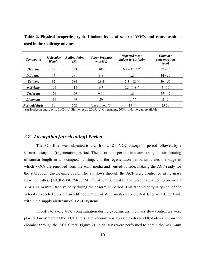
Table 2. Physical properties, typical indoor levels of selected VOCs and concentrations
used in the challenge mixture
Compound Molecular
Weight Boiling Point
(K) Vapor Pressure
(mm Hg)
Reported mean indoor levels (ppb)
Chamber concentration
(ppb)
Benzene 78 353 100 0.9 – 3.2 (a,b,c) 12 – 15
1-Butanol 74 391 8.8 n.d. 14 - 20
Toluene 92 384 28.4 3.3 – 12 (a) 40 – 50
o-Xylene 106 418 6.7 0.5 – 1.8 (a) 5 - 10
Undecane 156 469 0.41 n.d. 35 - 40
Limonene 136 449 20 1.4 (c) 2-10
Formaldehyde 30 252 (gas at room T) 17 (a) 15-30 (a) Hodgson and Levin, 2003; (b) Shimer et al, 2005; (c) Offermann, 2009; n.d.: no data available
2.2 Adsorption(aircleaning)Period
The ACF filter was subjected to a 24-h or a 12-h VOC adsorption period followed by a
shorter desorption (regeneration) period. The adsorption period simulates a stage of air cleaning
of similar length in an occupied building, and the regeneration period simulates the stage in
which VOCs are removed from the ACF media and vented outside, making the ACF ready for
the subsequent air-cleaning cycle. The air flows through the ACF were controlled using mass
flow controllers (MCR-50SLPM-D/5M, DS, Alicat Scientific) and were maintained to provide a
31.4 ±0.1 m min-1 face velocity during the adsorption period. This face velocity is typical of the
velocity expected in a real-world application of ACF media as a pleated filter in a filter bank
within the supply airstream of HVAC systems.
In order to avoid VOC contamination during experiments, the mass flow controllers were
placed downstream of the ACF filters, and vacuum was applied to draw VOC-laden air from the
chamber through the ACF filters (Figure 2). Initial tests were performed to obtain the maximum

11
VOC adsorption capacity of the ACF media. The media was subject to a continuous adsorption
period lasting ~ 100 hours and the resulting data allowed an estimation of the adsorption capacity
and determination of parameters corresponding to a modified multi-component Freundlich
isotherm for the different VOCs on the surface of ACF. Subsequent to these adsorption capacity
studies, alternating adsorption and desorption studies were conducted to evaluate the
performance efficiency of the ACF media. The details of experimental conditions for these
experiments, and for experiments described subsequently, are given in Table S-1 (supporting
information).
An adsorption and regeneration cycle is defined as one adsorption period of the ACF and
one regeneration period following the adsorption period. Hence Cycle i represents the ith
adsorption phase and subsequent ith regeneration phase that follows the adsorption phase. Periods
of 24 and 12 hours were used for the adsorption period and different types of ambient air and
heated media regeneration techniques were studied. To measure the VOC removal efficiency of
the ACF, simultaneous air/VOC samples were collected upstream and downstream of the ACF
filter. Samples for VOCs (except formaldehyde) were collected periodically on Tenax-
Carbosieve sorbent tubes using a peristaltic pump for a period of 1 hour at the rate of ~30 mL
min-1. The samples were analyzed using a gas chromatography system (HP 6890 series GC) with
mass selective detector (HP 5973) equipped with a Gerstel TDSA2 thermal desorption inlet with
autosampler. Quantification was carried out using bromofluorobenzene as internal standard, with
calibration curves using authentic standards. Aldehyde sampling was also conducted periodically
on DNPH cartridges (Waters Sep-Pak, # WAT047205) using a peristaltic pump operating at ~ 1
L min-1 for a duration of 1 hour. DNPH cartridges were extracted with 2-mL aliquots
acetonitrile, and the extracts were analyzed by HPLC with UV detection at λmax = 360 nm
(Agilent 1200). From repeated quality control protocols developed in the laboratory, error in
concentration estimations of volatiles has been established to below 10%. Additionally, all
samples were duplicated to ensure repeatability and the values reported here is the average. The
error bars reported are the absolute difference between the duplicate data points. A calibration
curve for quantification was carried out using authentic standards of the dinitrophenyl hydrazone
of formaldehyde.

12
2.3 RegenerationPeriod
Two different modes of ACF regeneration were evaluated:
2.3.1 Unheated outdoor air regeneration
Unheated outdoor air was passed through the ACF filter after the completion of an
adsorption period. Two different air face velocities (6.28m min-1 and 0.31 m min-1) were utilized.
The direction of the regeneration air flow was opposite to that of the adsorption air flow.
Periodic Tenax and aldehyde samples were collected upstream and downstream of the ACF
media and analyzed by methods described above. Electro-thermal regeneration
The electro-thermal regenerative unit was created by clamping the activated carbon cloth
between two Teflon flanges. The mating surfaces of the flanges were covered with electrical
grade copper sheets in such a way that a voltage could be maintained across the ACF cloth. A
Powerstat variable autotransformer, (Type 3PN116C, Superior Electric Co.) was used to apply
the desired potential difference across the copper sheets. Temperature on the surface of the ACF
media was monitored and recorded using a thermocouple data logger (Extech Easy View 15).
The voltage was measured with a multimeter (Keithley 177 Microvolt DMM) and the current
across the cloth was measured with an amp meter. The ACF was heated to ~ 150 oC for all of the
electro-thermal regeneration tests. Three different face velocities (5.24 m min-1, 0.52 m min-1 and
0.11 m min-1) were explored to identify the optimum conditions to achieve high regeneration
efficiency with minimal energy consumption. Effect of Relative Humidity on Adsorption and
Regeneration
Additional experiments were carried out at 75% relative humidity to evaluate the effect
of humidity on adsorption and regeneration of the ACF. All of the adsorption tests (face velocity
of 31.4 m min-1) with 75% humidity were conducted for a period of 12 hours followed by a short
heated regeneration for 15 minutes at 0.52 m min-1 at 150 oC. Upstream and downstream VOC
samples were collected at the end of 12 hours to evaluate the effect of humidity on adsorption
capabilities of the carbon fiber in the presence of humidity.

To evaluate the effect and explore the option of using humidity to effectively regenerate
the ACF, regeneration experiments were carried out with saturated humid air. The 12 hour
adsorption period for these tests was maintained at the ambient air level humidity conditions of
20 – 40%. The regeneration was conducted for a period of 6 hours at > 75% RH at room
temperature at a face velocity of 6.28 m min-1. VOC samples were collected during the
adsorption cycle to evaluate the effect of humid air regeneration on the adsorption capabilities of
ACF.
2.4 Determinationofremovalandregenerationefficiencies
The VOC percent removal efficiency of a given cycle, a,i was calculated as indicated in
equation 1. The regeneration efficiency of a given cycle r,i was calculated as the ratio of the
mass of VOC desorbed during a regeneration run to the net mass of VOC accumulated on the
ACF from all of the previous adsorption periods using equations 2a and 2b. The average mass
accumulated ma,i or removed mr,i during a single adsorption / regeneration period was calculated
using equations 3a and 3b.
a,i C0,i Ca,i (t)
C0,i
100% (1)
ia
irir M
M
,
,,
(2a)
i
k
i
kkrkaia mmM
1
1
1,,, (2b)
Mr,i mr,k
k1
i1
(2c)
dtQtCCm a
t
kakka 0
,,0, (3a)
13

t
rkrkr dtQtCm0
,, (3b)
where, a,i is the percent removal efficiency, r,i is the regeneration efficiency, Mr,i is the mass of
VOC desorbed at the end of the ith regeneration period (ng), Ma,i is the total mass of the VOC
adsorbed in the ACF filter at the end of the ith adsorption period (ng). C0,k is the inlet
concentration of the kth adsorption period of the VOC under study (ng m-3), Ca,k is the outlet
concentration obtained downstream of the filter during the kth adsorption period (ng m-3), Qa is
the adsorption air flow rate (m3s-1), ma,k is the mass of VOC adsorbed in the ACF filter during the
kth adsorption period (ng). Cr,k is the outlet concentration obtained downstream of the filter
during the kth regeneration period (ng m-3), Qr is the regeneration air flow rate (m3 s-1), and mr,k is
the mass desorbed during the kth regeneration period (ng).
3 Results
3.1 Modified multi‐component adsorption isotherm and VOC holding
capacityofACF
A Freundlich multi-component isotherm model (Sheindorf et al., 1981) was adopted to
develop an approximate isotherm for the different VOCs. There are numerous studies (Cal., et al,
1997, Singh et al., 2002, Ramirez et al., 2005, Yao et al., 2009c) that have modeled a single
component adsorption isotherm for activated carbon; however, very little research has been
performed on the modeling of multi-component interaction on ACF cloth. Yao et al., 2009 have
developed isotherms for toluene adsorption and modeled the mono-component adsorption
parameters. The multi-component adsorption isotherm expressed in terms of sorbate mass as
described by Sheindorf et al., 1981 is written as follows:
1
1
ink
jjijiii CaCKq , (4)
14

15
where qi is the maximum adsorbed mass of component i per unit mass of media (expressed in µg
g-1), Ki is the mono-component Freundlich adsorption constant for the component i, ai,j are
dimensionless adsorption competition coefficients for multi-component system which is equal to
unity when i=j (ai,i =1), ni is the isotherm exponent of the component i, Cj is the concentration of
the component j, and k is the total number of components in the system. This model is valid only
for compounds where the mono-component adsorption Freundlich isotherm is applicable.
The dimensionless adsorption breakthrough profile for the VOC mixture studied in this
work is shown in the supporting information document (Figure S-1). The experiments were
conducted at the adsorption face velocity of 31.4 m min-1 and samples were collected
periodically. The saturation time was estimated to be ~ 97h. Since we performed a continuous
flow experiment to determine the bed life, the off-gassing of VOCs was observed in subsequent
measurements leading to values higher than 1 for Ca,i/C0,i as shown in Figure S-1. The
breakthrough period reported here is lower than the breakthrough values reported by Yao et al.,
(2009) and Das et al., (2004). Both these studies were accomplished with single component
adsorption, at different flow velocities with different adsorbent mass and the concentration
ranges studied by the latter are in the high ppm range, at least 3 orders of magnitude higher than
our study. The isotherm parameter n in case of single component Freundlich model tends to
increase with increase in concentration levels of the adsorbate (Yao et al., 2009, Das et al., 2004,
Cal et al., 1997). The exponential n values of the VOCs obtained from the multi-component
modeling in this study are different from the n values predicted by Yao et al., (2009) for a single
component model. The lower saturation period and different isotherm parameters obtained in this
study may be due to the behavior of the mixture of VOCs on the ACF surface leading to
competitive adsorption. However, the maximum total VOC adsorption capacity obtained from
this study are in agreement with the study by Yao et al., 2009 in which they show integrated
adsorption of 81.6 mg of toluene per gram of ACF over a saturation period of 197 hours as
opposed to 90.7 mg of VOC mixture per g of ACF obtained in this study.
The maximum adsorption capacity of the ACF cloth for the compounds under study,
under the experimental conditions employed, was determined experimentally by integrating the
area under the adsorption concentration profile for each compound. The values were estimated to

be 3.1, 4.8, 24.2, 7.8, 48.2, and 2.6 mg g-1for benzene, 1-butanol, toluene, o-xylene, undecane
and formaldehyde respectively (total VOC mass accumulated = 90.7 mg g-1). These experimental
values are in agreement with the values predicted by the isotherm developed in this study and are
within the 95% confidence interval.
The parameter estimation for the modified multi-component Freundlich isotherm
involved solving multi-variable linear equations simultaneously and reiterating the estimated
parameters to ensure convergence. The adsorption constant Ki for the different compounds under
study was either obtained from or determined by methods listed by Yao et al., 2009. After every
iteration, the ai,j values were substituted in equation 4 and Ki value was back calculated. This
process was repeated until the error difference of the predicted Ki from Yao et al., and the Ki
value back calculated from our ai,j values was less than 0.001. The isotherm parameters
estimated for benzene, 1-butanol, o-xylene, toluene, undecane and formaldehyde are listed in
Table S-2 (Supporting Information). The adsorption capacity for the challenge mixture,
evaluated to be 90.7 mg g-1, is close to the Ki estimated for 1-butanol (92.3 mg g-1) and toluene
(123 mg g-1); it is much higher than the parameters estimated for the two more volatile
constituents, benzene (7.6 mg g-1) and formaldehyde (1.8 mg g-1); and it is significantly lower
than Ki estimated for the constituents with higher tendency to adsorb to the carbon matrix, o-
xylene (259 mg g-1) and undecane (454 mg g-1).
One of the main aims of this isotherm study is to determine the bed life, i.e., the time
before the ACF bed becomes saturated and will no longer remove VOCs. Bed life (TB) can be
defined as follows (Yao et al., 2009):
i ini
iACFB C
q
Q
MT
,
(5)
where, MACF is the mass of activated carbon fiber (g), Q is the flow rate of the air stream to be
treated (L min-1), Ci,in is the inlet concentration of the component i of the multi-component VOC
stream (µg L-1). Hence, we could verify the consistency of the experimental results by estimating
the bed life of a mass of 1 g of ACF used to remove benzene, butanol, toluene, xylene, undecane
and formaldehyde at average concentrations of 4µg m-3, with an air flow of 1.8 m3 h-1 through
16

17
the ACF from equation 1-5. For these conditions the estimated bed life is approximately 103 hrs,
which is consistent with the values estimated from the experiments. The replacement of the ACF
media every 103 hours of operation is impractical, and hence periodic in-situ regeneration is
necessary for this scenario.
3.2 EvaluationofVOCaircleaningwithdifferentregenerationmethods
3.2.1 Adsorption – Regeneration cycles: Method I – Regeneration with room
temperature outdoor air
ACF performance using two different regeneration flow rates with outdoor air was evaluated to
identify the optimum method for efficient VOC removal from supply air. New ACF media was
saturated initially based on bed life (equation 5) estimates from section 3.1 and regenerated for a
period of 12 hours before subjecting it to alternate adsorption and regeneration phases.
3.2.1.1. Regeneration with outdoor air at 6.28 m min-1
Figure 3 shows the VOC removal efficiency achieved for different cycles for different VOCs in
the mixture with an adsorption period face velocity of 31.4 m min-1. The levels of the VOCs in
this study were maintained below 50 ppb. It was found that the ACF had a removal efficiency of
40 – 70% in the first cycle, which decreased to 20 – 45% in the subsequent cycles. All of the
adsorption-regeneration cycles studied with a 6.28 m min-1 regeneration air velocity for a period
of 12 hours are not shown in the Figures 3 (a) – (f) to eliminate overlap of data points for a clear
demonstration. Limonene was added to the VOC mixture in cycles 6 – 12 and showed an
average removal efficiency of ~ 35%. Formaldehyde was not present in adsorption period 4 and
it was found that there was a very high initial adsorption of > 90% for all of the VOCs, thus
suggesting a significant competitive effect even for compounds with very low Ki during an initial
transient period. However, by the end of a 24–h cycle, the removal efficiency for all compounds
decreased to values that are comparable to the other cycles (in the presence of formaldehyde).
Table 3 lists the regeneration efficiency r,i (as estimated from equation 2a) obtained for various
VOCs for the different adsorption – regeneration cycles. The regeneration efficiency increased in
the second cycle and decreased subsequently. We speculated that this behavior may be explained

18
by strong initial adsorption of the volatiles as a monolayer on the ACF surface and weaker
multilayer adsorption of additional volatiles. The regeneration process does not remove all of
the adsorbed VOCs, thus, as the amount of the VOCs retained on the ACF increased, the VOC
amount removed by the cloth from the inlet stream decreased, leading to lower VOC removal
efficiency (Figure 3). . The regeneration efficiency increases in the second cycle (Table 3) due to
ease of desorption of multi-layer VOCs that are not in direct contact with the ACF surfaces. As
the surface adsorption reaches steady state, subsequent cycles show lower regeneration
efficiency, as shown in Table 3.
Table 3. Regeneration efficiency r,i (as estimated from equation 2a) for different compounds using room temperature outdoor air for regeneration (face velocity during regeneration = 6.3 m min-1).
Compound Cycle 1 Cycle 2 Cycle 3 Cycle 4 Cycle 5
Benzene 0.05 0.76 0.13 0.19 0.12
Butanol 0.03 0.11 0.12 0.15 0.30
Toluene 0.01 0.40 0.30 0.12 0.28
O-xylene 0.10 0.73 0.32 0.17 0.11
Undecane 0.04 0.22 0.20 0.11 0.08
Formaldehyde 0.05 0.56 0.04 0.01 0.54

0
20
40
60
80
100
0 5 10 15 20 25
Re
mo
va
l Pe
rce
nta
ge
Time, hrs
Benzene
Cycle 1 Cycle 2 Cycle 3 Cycle 4 Cycle 5
0
20
40
60
80
100
0 5 10 15 20 25
Re
mo
va
l Perc
en
tag
e
Time, hrs
1-Butanol
Cycle 1 Cycle 2 Cycle 3 Cycle 4 Cycle 5
(a) (b)
0
20
40
60
80
100
0 5 10 15 20 25
Re
mo
va
l Pe
rce
nta
ge
Time, hrs
Toluene
Cycle 1 Cycle 2 Cycle 3 Cycle 4 Cycle 5
0
20
40
60
80
100
0 5 10 15 20 25
Re
mo
va
l Pe
rce
nta
ge
Time, hrs
O-Xylene
Cycle 1 Cycle 2 Cycle 3 Cycle 4 Cycle 5
(c) (d)
0
20
40
60
80
100
0 5 10 15 20 25
Re
mo
va
l Pe
rce
nta
ge
Time, hrs
Undecane
Cycle 1 Cycle 2 Cycle 3 Cycle 4 Cycle 5
0
20
40
60
80
100
0 5 10 15 20 25
Re
mo
va
Pe
rcen
tag
e
Time, hrs
Formaldehyde
Cycle 1 Cycle 2 Cycle 3 Cycle 5
(e) (f)
Figure 3. Removal efficiency time profile for (a) benzene, (b) 1-butanol, (c) toluene, (d) o-xylene, (e) undecane, (f) formaldehyde for different adsorption – regeneration cycles with adsorption face velocity of 31.3 m min-1 and regeneration face velocity of 6.3 m min-1
19

3.2.1.2. Regeneration with outdoor air at 0.31 m min-1 face velocity
Additional experiments after 12 cycles with outdoor air regeneration at 6.3 m min-1 were
performed to test the efficiency of regeneration using a much lower air flow. The ACF cloth was
regenerated for 53 hours using the same air face velocity of 6.3 m min-1 prior to additional
testing. The additional adsorption experiments of 24 hours duration were followed by
regeneration with face velocities of 0.3 m min-1 over periods of 12 hours. These cycles are
named as Cycle’ to distinguish from the cycles with a regeneration face velocity of 6.3 m min-1.
Cycle’1 follows the 53 hour regeneration after Cycle 12 of the regeneration system discussed
above (at 6.3 m min-1). The adsorption of more sorptive species improved significantly when
preceded by the prolonged regeneration time (Cycle’1). Subsequently, the regeneration
efficiency decreased rapidly and breakthrough (release of VOCs by the ACF media during the air
cleaning cycle) was achieved at the end of cycle ‘3 for most constituents, and at the end of
cycle’4 for the less volatile constituents (limonene and undecane). These results show that
decreasing the regeneration airflow rate decreased the subsequent VOC removal efficiency to an
unacceptable level (Figure 4).
20
-20
0
20
40
60
80
100
Per
cent
Rem
oval
afte
r 24
hou
rs
Cycle' 1 Cycle' 2 Cycle' 3 Cycle' 4 Cycle' 5

21
Figure 4. VOC removal efficiency for 24 hour adsorption period with a room temperature outdoor air regeneration face velocity of 0.3 m min-1 for 12 hours. Negative values indicate downstream levels higher than upstream concentrations due to ACF saturation.
3.2.2 Adsorption – Regeneration cycles: Method 2- Regeneration with electro-
thermal heating of ACF cloth
The electro-thermal regeneration method has been explored in a number of studies to
obtain optimal loading and regeneration conditions for ACF fiber systems (Yao et al., 2009,
Sullivan et al., 2001, Dombrowski et al., 2004). These studies utilized a single VOC at different
concentrations. Our study concentrates on optimizing electro-thermal regeneration process for
multi-VOC system to obtain an ACF system with maximum energy efficiency.
The adsorption period face velocity of the polluted air stream was maintained at 31.4 m
min-1 for all of these experiments. The temperature of the ACF fiber during regeneration was
maintained at 150 oC for 2 hours and the regeneration air flow rates were varied. In the heated
regeneration phase, three face velocities of 5.24, 0.52 and 0.11 m min-1 were studied to
determine the optimum regeneration efficiency. Figure 5 shows the VOC percent removal
efficiency for different adsorption-regeneration cycles. The three flow regimes are marked on the
plot in Figure 5. The regeneration face velocity of 5.24 m min-1 was maintained for Cycles 1 – 4.
The regeneration face velocity of 0.52 m min-1 was maintained for Cycles 5 – 7 and the
regeneration face velocity of 0.11 m min-1 was maintained for Cycles 8 – 12.

0
10
20
30
40
50
60
70
80
90
0 2 4 6 8 10 12
Percent Removal after 24 hours
Cycle Number14
Benzene 1-Butanol Toluene o-Xylene Limonene Undecane Formaldehyde
Regeneration at 5.24 m min-1
Regeneration at 0.52 m min-1
Regeneration at 0.11 m min-1
Figure 5. VOC percent removal efficiency for a 24-h adsorption period with different electro-thermal regeneration air stream face velocities and a regeneration temperature of 150 oC for two hours.
Different percent removal efficiencies were observed for different VOCs for regeneration
face velocities using the electro-thermal regeneration method. The percent removal of
formaldehyde decreased consistently for regeneration cycles with low face velocities. For
compounds such as benzene, 1-butanol and toluene, with relatively weaker adsorption to ACF,
the percent removal efficiency decreased with decrease in regeneration flow. Instead, o-Xylene,
limonene and undecane showed a consistent performance with high and almost constant removal
efficiency for each cycle (~62%, 71% and 74%, respectively). These three compounds have a
high Freundlich adsorption capacity constant (Ki) (Table 3) compared to formaldehyde, benzene,
toluene and 1-butanol. These compounds can adsorb strongly on the carbon fiber surface and
22

23
displace the more volatile species (e.g., benzene and toluene), leading to a decreased percent
removal efficiency as shown in Figure 5. Removal of formaldehyde is consistently lower for all
regeneration conditions. The regeneration efficiency of the electro-thermal desorption system
was studied for 5.2 m min-1 and 0.52 m min-1 regeneration velocities and the results are listed in
Table 4. The regeneration efficiency depended on the flow rate of the regeneration stream, very
similar to the results found in Method I discussed above.
Table 4. Regeneration efficiency r,i of different compounds under different face velocities using electro-thermal regeneration at 150 oC for two hours.
Regeneration Face Velocity Compound
5.2 m min-1 0.52 m min-1
Cycle 1 Cycle 2 Cycle 3 Cycle 4 Cycle 5 Cycle 6 Cycle 7
Benzene 0.41 0.42 0.43 0.44 0.45 0.36 0.31
Butanol 0.61 0.62 0.64 0.65 0.66 0.42 0.36
Toluene 0.64 0.61 0.58 0.55 0.52 0.45 0.37
o-Xylene 0.85 0.83 0.81 0.79 0.68 0.58 0.59
Undecane 0.86 0.84 0.82 0.84 0.68 0.57 0.55
Limonene 0.88 0.84 0.84 0.84 0.71 0.70 0.72
Formaldehyde 0.87 0.83 0.80 0.76 0.73 0.70 0.68
3.2.3 Adsorption – regeneration cycles: Methods 1 and 2 with shorter adsorption
(air cleaning) cycles
3.2.3.1. Shorter Adsorption and Regeneration Cycles
One main aim of this project was to identify an optimum cycle to implement ACF filter
system to remove VOCs in HVAC units as energy retrofit in office buildings. For this purpose,

24
we studied shorter adsorption and regeneration periods. The duration of the adsorption period
was reduced from 24 hours to 12 hours. In a building with only work-day occupancy, periods of
HVAC operation may be close to approximately 12 hours. Both outdoor ambient air regeneration
and electro-thermal regeneration were studied with 12 hours adsorption periods. The outdoor air
regeneration was carried out at air face velocities of 4.2 m min-1 for duration of 6 hours and the
electro-thermal regeneration by heating the ACF cloth at 150 oC was carried out at air face
velocities of 1.1 m min-1 for a duration of 15 minutes.
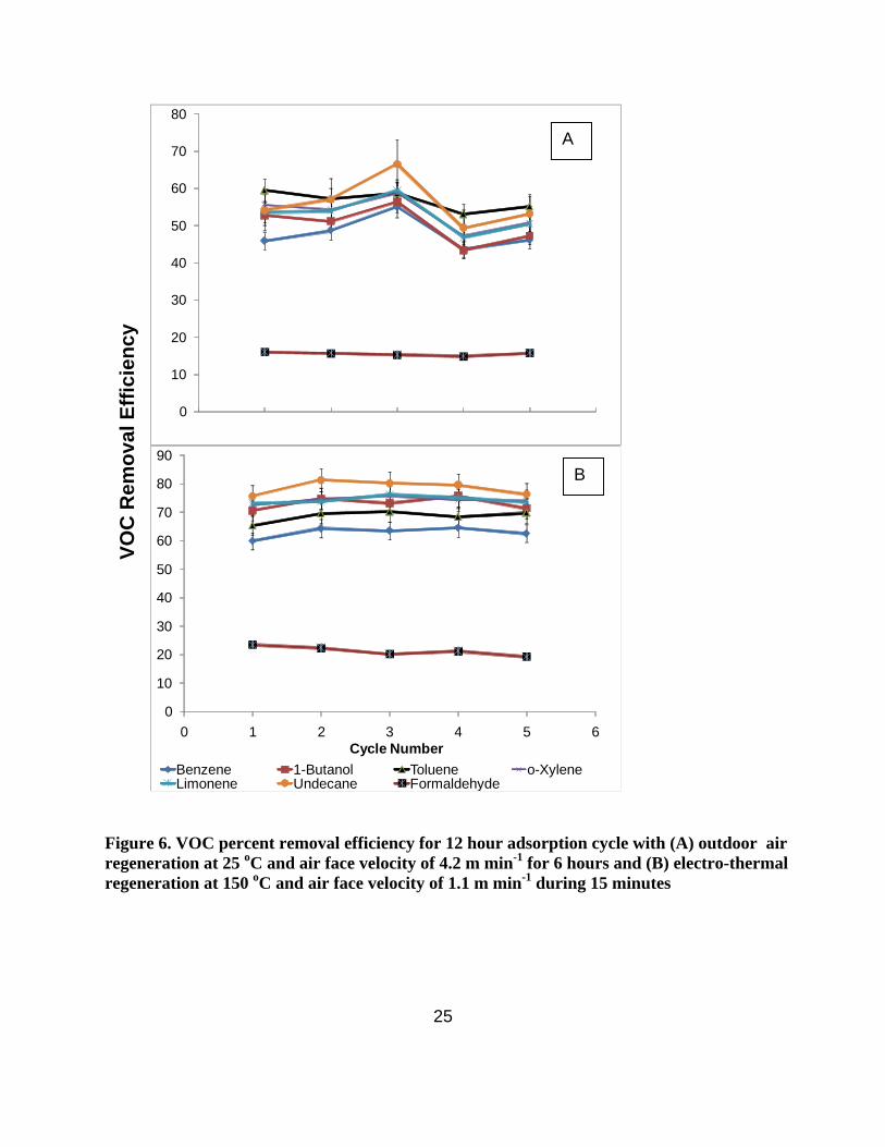
3.2.3.2. Regeneration with outdoor air at a face velocity of 4.2 m min-1
Figure 6(A) shows the VOC percent removal efficiency for 12-h adsorption periods with
umheated outdoor air regeneration. It was found that the ACF filter had a relatively consistent
removal efficiency for all of the VOCs studied. The formaldehyde removal was low (~16%), but
at the lower bound of the 15% to 20% target needed to compensate for a 50% reduction in
outdoor air. The VOC removal efficiencies at the end of 12 hour cycles were much higher than
the VOC removal efficiency observed for 24-h cycles.
3.2.3.3. Electro-thermal regeneration at a face velocity of 1.1 m min-1
Figure 6(B) shows VOC percent removal efficiency obtained at the end of 12 hours with
electro-thermal regeneration. The VOC removal efficiency was higher than that observed at the
end of 24 hours with a comparable regeneration flow rate. Further, the removal efficiency was
also consistent for all of the VOCs studied, in contrast to the prior findings (Figure 4) where the
removal efficiency decreased to a minimum at the end of 24 hours. The formaldehyde removal
efficiency was low but met the the 15% to 20% target. The duration of regeneration was small
compared to the duration of regeneration for unheated outdoor ambient air regeneration.
25
0
10
20
30
40
50
60
70
80V
OC
Rem
ova
l Eff
icie
ncy
0
10
20
30
40
50
60
70
80
90
0 1 2 3 4 5 6Cycle Number
Benzene 1-Butanol Toluene o-XyleneLimonene Undecane Formaldehyde
B
A
Figure 6. VOC percent removal efficiency for 12 hour adsorption cycle with (A) outdoor air regeneration at 25 oC and air face velocity of 4.2 m min-1 for 6 hours and (B) electro-thermal regeneration at 150 oC and air face velocity of 1.1 m min-1 during 15 minutes

26
3.3 Effectofhighrelativehumidityonadsorptionandregeneration
The results of the adsorption experiments with 75% RH at a face velocity of 31.4 m min-1
and regeneration at 150 oC are presented in Figure S-2 of the supporting information. The
percent removal of non polar compounds by the ACF such as benzene decreased by <5% while
that of compounds soluble in water such as formaldehyde increased by about 10%. The heated
regeneration of the activated carbon was effective in restoring the adsorption properties of the
ACF.
Two additional experiments were conducted to explore the possibility of using
humidified air as to enhance the regeneration efficiency. Results obtained were not encouraging,
and this method was not explored further. A comparison between regeneration using ambient air
(RH = 20-40 %) and high humidity conditions (RH = 80 %) is presented in supporting
information in Figure S-3.
3.4 PredictionofimpactsonindoorVOClevels:Massbalancemodel
A simple mass balance model (flow diagram shown in Supporting Information, Figure S-
4) was developed to analyze the effect of using ACF media to remove VOCs from indoor air.
Scenarios with two different initial ventilation rates were studied to predict the performance of
ACF when ventilation rates are subsequently reduced. In all scenarios the, volume-normalized
supply air flow rate, equal to rate of flow of outdoor air plus recirculated-indoor air through the
air cleaner divided by the indoor volume, was 4 h-1. This is a typical volume normalized supply
air flow rate in a U.S. commercial building.
3.4.1 Scenario 1: Moderate initial ventilation rates
Base Case: The air handling system operates without an ACF filter bed air cleaning unit,
an outdoor air ventilation rate of 0.8 h-1 and a volume-normalized VOC source emission rate of
6.4 ppb h-1 for each VOC.

Case 1.1: Air handling system with ACF filter bed air cleaning unit with heated outdoor
air regeneration and outdoor air ventilation exchange rate of 0.4 h-1 (50% reduction in
ventilation).
Case 1.2: ACF filter bed air cleaning unit with unheated outdoor air regeneration and
outdoor air ventilation rate of 0.4 h-1 (50 % reduction in ventilation).
3.4.2 Scenario 2: High initial ventilation rates
Base Case: The air handling system operates without an ACF filter bed air cleaning unit,
at an outdoor air ventilation rate of 1.2 h-1 and a volume-normalized VOC source emission rate
of 6.4 ppb h-1 for each VOC.
Case 2.1: Air handling system with ACF filter bed air cleaning unit with heated outdoor
air regeneration, outdoor air ventilation rate of 0.6 h-1 (50% reduction in ventilation.
Case 2.2: ACF filter bed air cleaning unit with unheated outdoor air regeneration and
outdoor air ventilation rate of 0.6 h-1 (50 % in ventilation)
The VOC air cleaning effectiveness ratio (Ri) for a given VOC i, is defined as the ratio of
the indoor VOC concentration with the ACF filter bed installed in the system to the VOC
concentration without the ACF system (equation 6). A lower air cleaning effectiveness ratio
denotes a better performing ACF unit. Ri ≤ 1, signifies that the air cleaning technology maintains
a lower indoor VOC concentration than the base case system with twice the ventilation rate. The
air cleaning effectiveness ratio can also be calculated from the air exchange rates and VOC
removal efficiency of the ACF system as shown in equation 7.
ACFnoi
ACFii C
CR
(6)
ivrACFvriv
viACFvri XNSNNN
NNSR
,0,
, 1
(7)
where [Ci]no-ACF is the indoor concentration of the VOC species i with an air handling unit
without ACF filter bed, [Ci]ACF is the indoor concentration of the VOC species i with an air
27

28
handling unit with an ACF filter bed, Sr is the emission rate source concentration per unit
volume, Nr is the volume-normalized supply air flow , Nv is the number of air changes with
outdoor air in the scenario without ACF filter bed, Nv-ACF is the number of air changes with
outdoor air in the scenario with ACF filter bed, X0,i is the concentration of VOC entering from
outdoors through ventilation (assumed to be 2 ppb for all our model calculations), and i is the
percent removal efficiency of the ACF filter system for a given species i.
The removal efficiency of different VOCs tested in our experiments and the
corresponding Ri values for different ventilation scenarios and corresponding cases are listed in
Table S-3 (Supporting Information). It was observed that in both scenarios of low and high
ventilation rates, the system equipped with ACF filter bed and 50% reduced ventilation
performed better than the system without ACF filter bed, with Ri <1 (in the range 0.21 – 0.72) in
all cases for all VOCs. This was true even in the case of formaldehyde for which the VOC
removal percent was significantly lower than for other organic compounds studied in this project
(Rformaldehyde = 0.56). It was also observed that cases in which ACF was regenerated by heating
have lower Ri (in the range 0.21-0.56) values compared to the corresponding cases in which ACF
was regenerated with unheated outdoor air (between 0.26 and 0.72). This shows that the heated
regeneration method improved ACF VOC removal performance compared to the unheated
outdoor air regeneration method.
3.5 Energy consumption associatedwith the implementation of anACF
filterbedsystem
The pressure drop across the ACF filter is low (in the range 30 Pa) relative to total
supply-airstream pressure drops in commercial air handlers and does not contribute significantly
to the overall operational cost of HVAC systems. The main additional operational cost of an
ACF filter bed in an HVAC system is the energy required to regenerate the ACF cloth. The
energy consumption costs were computed for different regeneration face velocities and
temperatures, in order to provide a first-order estimation of energy savings that may be achieved
by implementing this technology. Net energy required to regenerate the system was estimated as

29
a sum of the energy required to heat the ACF cloth, heat the regeneration air passing through the
cloth and the energy consumed by a fan to circulate air through the system. The energy
consumption and cost estimates for different ratios of adsorption to regeneration face velocity
and regeneration temperature are listed in Table 5. For reference, a U.S. average annual
ventilation cost in offices was also estimated by analyzing data from Benne et al (2009), Grifith
et al. (2009), and Persily and Gorfain (2008). It was estimated that the unheated outdoor air
regeneration consumed the least energy. The most realistic condition for optimal operation with
heated regeneration would be operating the ACF at 150 oC at regeneration air velocities that are
1/30 of the velocities during air cleaning adsorption periods. With this operational strategy, the
annual energy cost estimate for providing a unit of VOC free air with an ACF filter systems is
15% of the estimated U.S. average cost of providing the same amount of VOC removal by
ventilation. Thus, with a 50% reduction in outdoor air, total building ventilation energy cost is
reduced by approximately 35%. With unheated outdoor air regeneration, which also yielded
good VOC control performance, the total building ventilation energy cost is reduced by almost
50%, as the regeneration energy is insignificant. These preliminary energy cost estimates for
operating an ACF system show that incorporating the ACF filter bed in a HVAC system can
effectively contribute substantially towards reducing ventilation energy consumption.

30
Table 5. Annual regeneration energy cost estimates for the electro-thermal regeneration system and savings obtained from ventilation costs.
Ratio of adsorption to regeneration face velocity
Regeneration temperature
Net energy required to produce 1m3 s-1 of VOC
free air per regeneration period
Annual regeneration cost per unit rate of VOC
free air*
Annual Ventilation cost per unit rate of
VOC free air
oC (KWH /( m3s-1)/cycle) ($/m3s-1) ($/m3s-1)
150 0.35 9 389 300
200 0.48 13 389
150 2.15 56 389 30
200 2.99 78 389
20 0.22 6 389
150 10.4 270 389 6
200 14.3 371 389 * Assumes 260 regenerations in a year
4 Summary and Conclusions
The ACF system has been studied for a mixture of typical indoor VOCs, and the results
indicate that this is a very promising technology. ACF cloth media has a long adsorption life
time and can be effectively used for removing indoor VOCs with periodic regeneration. The
adsorption isotherms of the studied VOCs onto the ACF cloth suggest that it will take about
~100 hours to fully saturate the ACF media when challenged with air containing realistic
concentrations of a range of indoor VOCs. The results from periodic adsorption and desorption
experiments show that the ACF media can be easily regenerated after a 12 or 24 hour period of
air cleaning. Additional studies are needed to establish the effect of oxidants such as ozone,
optimal regeneration conditions, system lifetime and overall costs. Currently efforts are being
taken to study the effect of ozone on the ACF system. Studies by Gundel et al., (2002) show that
ozone can be effectively removed by using carbon based air cleaning systems. Lee and

31
Davidson, (1999) showed that ozone can react and destroy the structural properties of ACF
leading to lower performance. However the material tested is different from the material used in
this study and the regeneration methods considered in their study was ineffective. Hence it is
very difficult to generalize the detrimental effect of ozone on ACF performance based on limited
available evidence.
Our experiments also showed that regeneration of the ACF media at 150 oC proved to be
effective in improving the VOC air cleaning efficiency relative to regeneration with unheated
outdoor air. While regeneration was better with the heated media, results with unheated ACF
were also very acceptable, suggesting that an optimal usage of ACF may not necessarily include
a heating phase on every cycle. Instead, periodic heating after a (relatively large) number of
cycles may be sufficient to remove strongly-adsorbed species that otherwise would buildup
under room temperature operation. The VOC removal efficiencies were increased when the
adsorption time was reduced to 12 hours from 24 hours. A mass balance model shows that an
HVAC system equipped with an ACF filter bed, with either unheated or heated outdoor air
regeneration, can reduce indoor VOC concentrations even when ventilation rates are reduced by
50%. Calculations indicated that reducing ventilation rates by 50% and using of ACF air
cleaning with heated or unheated outdoor air will result in substantial energy savings.
Acknowledgments
This work was supported by the Assistant Secretary for Energy Efficiency and Renewable
Energy, Building Technologies Program of the U.S. Department of Energy under Contract No.
DE-AC02-05CH11231.The authors thank Jerome Lam, Colin McCormick and Joe Hagerman of
DOE for program management, R. Maddalena, M. Sleiman, M. Russell, T. Hotchi, and A.
Montalbano for technical assistance, and L. Gundel and M. Apte for reviewing a report on which
this paper is based.

32
References
Bastani, A., Lee, C-S, Haghighat, F., Flaherty, C. and Lakdawala, N. Assessing the performance of air cleaning devices – A full-scale test method. Building and Environment 2010, 45, 143-149.
Benne, K., Griffith, B., Long, N., Torcellini, P. Assessment of the energy impacts of outside air in the commercial sector. NREL/TP-550-41955. Golden, CO, National Renewable Energy Laboratory, 2009.
Das, D., Gaur, V and Verma, N. Removal of volatile organic compound by activated carbon fiber. Carbon 2004, 42(14): 2949-2962.
Dombrowski, K. D., Lehmann, C. M. B., Sullivan, P. D., Ramirez, D., Rood M. J., and Hay K. J. Organic vapor recovery and energy efficiency during electric regeneration of an activated carbon fiber cloth adsorber. Journal of Environmental Engineering-ASCE 2004, 130(3): 268-275.
Cal, M.P., Rood, M.J., Larson, S.M. Gas Phase Adsorption of Volatile Organic Compounds and Water Vapor on Activated Carbon Cloth; Energy Fuels 1997, 11, 311-315.
Fisk, W. J. Can sorbent-based gas phase air cleaning for VOCs substitute for ventilation in commercial buildings?. Proceedings of the IAQ 2007 Healthy and Sustainable Buildings. ASHRAE, Atlanta, 2007.
Griffith, B., Long, N., Torcellini, P. and Judkoff, R. Methodology for modeling building energy performance across the commercial sector, . NREL/TP-550-41956. Golden, Co. National Renewable Energy Laboratory, 2008.
Gundel, L., Sullivan, D. P., Katsapov, G. Y., Fisk, W. J. A Pilot Study of Energy Efficient Air Cleaning for Ozone, Report LBNL-51836, Lawrence Berkeley National Laboratory, 2002.
Haghighat, F., Lee, C-S., Pant, B., Bolourani, G., Lakdawala, N., Bastani, A. Evaluation of various activated carbons for air cleaning – Towards design of immune and sustainable buildings. Atmos. Environ. 2008, 42, 8176-8184.
Hodgson, A.T.and Levin, H. Classification of measured indoor volatile organic compounds based on noncancer health and comfort considerations. LBNL report # 53308, Lawrence Berkeley National Laboratory, 2003. http://eetd.lbl.gov/ie/pdf/LBNL-53308.pdf
Liu, R. T. An in-situ regenerative adsorber for the control of indoor VOCs – activated carbon fibers. Proceedings of IAQ’92, pp. 257 – 261. ASHRAE, Atlanta, 1992.

33
Lorimier, C., Subrenat, A., Le Coq L., and Le Cloirec, P. Adsorption of toluene onto activated carbon fibre cloths and felts: Application to indoor air treatment. Environmental Technology 2005, 26(11): 1217-1230.
Offermann, F. J. Ventilation and Indoor Air Quality in New Homes. California Air Resources
Board and California Energy Commission, PIER Energy‐Related Environmental Research
Program. Collaborative Report. CEC‐500‐2009‐085, 2005.
http://www.arb.ca.gov/research/apr/past/04-310.pdf
Persily, A. K. and Gorfain J. Analysis of ventilation data from the U.S. Environmental Protection Agency Building Assessment Survey and Evaluation (BASE), 2008. http://www.fire.nist.gov/bfrlpubs/build04/art043.html
Ramirez, D., Qi, S. and Rood, M.J. Equilibrium and Heat of Adsorption for Organic Vapors and Activated Carbons. Environ. Sci. Technol. 2005, 39, 5864-5871.
Sheindorf, C., Rebhun M. and Sheintuch M. A Freundlich-type multicomponent isotherm.
Journal of Colloid and Interface Science 1981, 79(1): 136-142.
Shimer, D.. Phillips, T.J. and Jenkins, P.L. Report to the California Legislature. Indoor Air Pollution in California, 2005. http://www.arb.ca.gov/research/indoor/ab1173/rpt0705.pdf
Singh, K.P., Mohan, D., Tandon, G.S. and Gupta, G.S.D. Vapor-Phase Adsorption of Hexane and Benzene on Activated Carbon Fabric Cloth: Equilibria and Rate Studies. Ind. Eng. Chem. Res., 2002, 41, 2480-2486.
Subrenat, A. and Le Cloirec P. Adsorption onto activated carbon cloths and electrothermal regeneration: Its potential industrial applications. Journal of Environmental Engineering-ASCE 2004, 130(3): 249-257.
Sullivan, P. D., Rood, M. J., Hay K. J. and Qi S. Adsorption and electrothermal desorption of hazardous organic vapors. Journal of Environmental Engineering-ASCE 2001, 127(3): 217-223.
Yao, M., Zhang, Q., Hand, D. W., Perram D. L. and Taylor R. Investigation of the Treatability of the Primary Indoor Volatile Organic Compounds on Activated Carbon Fiber Cloths at

34
Typical Indoor Concentrations. Journal of the Air & Waste Management Association 2009a, 59(7): 882-890.
Yao, M., Zhang, Q., Hand, D. W., Perram D. L. and Taylor R. Adsorption and Regeneration on Activated Carbon Fiber Cloth for Volatile Organic Compounds at Indoor Concentration Levels. Journal of the Air & Waste Management Association 2009b, 59(1): 31-36.
Yao, M., Zhang, Q., Hand, D. W., and Taylor R. Modeling of Adsorption and Regeneration of Volatile Organic Compounds on Activated Carbon Fiber Cloth. Journal of Environmental Engineering-ASCE 2009c, 135(12): 1371-1379.
35
Supporting Information
5 Energy Efficient Indoor VOC Air Cleaning with Activated Carbon Fiber (ACF) Filters
Meera A. Sidheswaran1, Hugo Destaillats1,2,*, Douglas P. Sullivan1,
Sebastian Cohn1 and William J. Fisk1
3. Lawrence Berkeley National Laboratory, Indoor Environment Department 4. Arizona State University, School of Sustainable Engineering and the Built Environment 5. * to whom correspondence should be addressed: [email protected]

36
Adsorption
Time, (h)
Regeneration
Type
Number of
Cycles
Regeneration
Face Velocity, m
min-1
Adsorption :
Regeneration face
velocity ratio
Regeneration
Time (h)
Regeneration
Temperature, oC
Special
Conditions
24 Outdoor air 12 6.28 5:1 12 25
No Formaldehyde
in Cycle 4 and
Limonene added
from Cycle 6
24 Outdoor air 5 0.31 100:1 12 25 -
24 Electrothermal 4 5.24 6:1 2 150 -
24 Electrothermal 3 0.52 60:1 2 150 -
24 Electrothermal 5 0.11 285:1 2 150 -
12 Outdoor air 5 4.2 8:1 6 25 -
12 Electrothermal 5 1.1 30:1 0.25 150 -
12 Electrothermal 5 0.52 60:1 0.25 150
RH of adsorption
was > 75%,
Regeneration was
using dry air with
RH < 3%
12 Humid air 5 6.28 5:1 6 25 RH of regeneration
was > 75%
Table S-1. Experimental Conditions

PublishedinBuildingandEnvironmenthttp://dx.doi.org/10.1016/j.buildenv.2011.07.002
37
ai,j Ki
(mg g-1) n
j
i Benzene
1-Butanol
Toluene o-Xylene Undecane Formaldehyde
Benzene 1 1.2 0.7 1.3 1.4 0.3 7.6 0.192
1-Butanol 0.9 1 1.7 0.4 1.3 0.2 92.3 0.413
Toluene 1.8 0.61 1 0.8 0.4 0.5 123 0.721
o-Xylene 0.8 1.9 1.3 1 0.7 0.3 259 0.802
Undecane 0.7 0.81 2.4 1.6 1 0.7 454 0.814
Formaldehyde 2.9 4.7 2.4 3.2 1.8 1 1.8 0.103 Table S-2. Multi-component Freundlich Isotherm parameters for VOCs
0
0.4
0.8
1.2
1.6
2
0 20 40 60 80 100 1
Ca.
i/C
o,i
Time, h20
benzene 1-butanol toluene o-xylene undecane
97 h
Figure S-1. Dimensionless adsorption profile for different VOCs on the surface of ACF

PublishedinBuildingandEnvironmenthttp://dx.doi.org/10.1016/j.buildenv.2011.07.002
0
10
20
30
40
50
60
70
80
90
0 1 2 3 4 5 6
VOC Removal Efficiency
Cycle Number
benzene 1-butanol toluene o-xylene limonene undecane formaldehyde
Figure S-2. VOC removal efficiency of ACF for 12 hour adsorption cycle at face velocity of
31.4 m min-1 with 75% RH and 15 min. regeneration period at 150 oC at a face velocity of
3.1 m min-1
38

PublishedinBuildingandEnvironmenthttp://dx.doi.org/10.1016/j.buildenv.2011.07.002
-20
-10
0
10
20
30
40
50
60
70
80
VOC Removal Efficiency
Wet Regeneration, 80% RH Ambient Air Regeneration, ~20 - 40% RH
Figure S-3. VOC removal efficiency at the end of Cycle 3 for regeneration using humidified air (80% RH) and ambient conditions (20-40 % RH) for a face velocity of 6.3m min-1 and a 12 hour adsorption cycle.
39

PublishedinBuildingandEnvironmenthttp://dx.doi.org/10.1016/j.buildenv.2011.07.002
40
Scenario Case Compounds Removal
Efficiency* (%) Nv
(h-1) Nv-ACF (h-1)
Sr (ppb/h)
Ri
Benzene 60 0.26
1-Butanol 71 0.23
Toluene 65 0.24
o-Xylene 73 0.22
Limonene 73 0.22
Undecane 76 0.21
1.1
Formaldehyde 24 0.56
Benzene 46 0.33
1-Butanol 53 0.29
Toluene 60 0.26
o-Xylene 56 0.28
Limonene 54 0.29
Undecane 54 0.29
Low ventilation rate
1.2
Formaldehyde 16
0.8 0.4 6.4
0.72
Benzene 60 0.36
1-Butanol 71 0.31
Toluene 65 0.33
o-Xylene 73 0.30
Limonene 73 0.30
Undecane 76 0.29
2.1
Formaldehyde 24 0.71
Benzene 46 0.44
1-Butanol 53 0.40
Toluene 60 0.36
o-Xylene 56 0.38
Limonene 54 0.39
Undecane 54 0.39
High ventilation rate
2.2
Formaldehyde 16
1.2 0.6 6.4
0.88 *Determined experimentally (Case 1.1 and 2.1 heated regeneration at 150 –C at a face velocity of 1.1 m min-1 for a period of 15 min, Case 1.2 and 2.2 unheated regeneration at 25 oC at a face velocity of 4.2 m min-1 for a period of 6 hours. Removal efficiency averaged over 10 cycles for all of the cases after achieving steady state performance)
Table S-3. Removal efficiency and air cleaning effectiveness ratio for ACF filter fiber
system with different regeneration methods.

PublishedinBuildingandEnvironmenthttp://dx.doi.org/10.1016/j.buildenv.2011.07.002
Nv-ACF
41
Xr,i (ppb)
fan Catalyst Nr, Xr,i Outdoor Air
X0,i
ACF Filter Unit
Sr,i
Nr, Xs,i VOC source
20-m3 stainless-steel chamber
Figure S-4. Mass balance Model