efficient energy systems 3315eng - griffith university · efficient energy systems ... david j...
TRANSCRIPT

Efficient Energy Systems
http://cleantechnica.com/2012/01/09/republican-fight-against-new-light-bulb-efficiency-regulations/
3315ENG

TopicsPower and EnergyEnergy AuditingEfficient lightingEnergy HarvestingMotors and DrivesHeatingTransportation.

Resourcesresource material available on Learning@ (course content)or directly at http://maxwell.me.gu.edu/sok/ees/index.html

Sustainable energy - without all the hot air David J MacKay

AssessmentLaboratories 30%Energy Audit 10%Final Exam 60%

Laboratory work will be graded on the spot and marks will be assigned in proportion to each students ability at
■ Completing any pre-lab work■ Following the laboratory instructions■ Setting up and running the equipment■ Recording and analysing the results■ Demonstrating understanding of the principles
To be eligible to pass the course, students are required to attempt and complete all types of assessment and must demonstrate a reasonable degree of competence in the required learning objectives for each type of assessment.
Therefore, to obtain a pass or better grade for the course, the student must:1) achieve an aggregate mark of at least 50% overall2) achieve at least 40% for the final examination3) achieve at least 50% for the laboratory component

Introduction to Power and Energy
The basic stuff we all need to know
[1] Fundamentals of Electrical Engineering and Electronics., Tony R Kuphaldt.
Mains voltageThe mains voltage in Australia is 240V, Isn’t it??? What does that mean?
Actually in 2000 the Australian mains was redefined as 230V with tolerance of +10% or -6% (AS 60038).
The mains is AC. What does the 230V refer to?

Can we calculate the RMS???


Simple resistive circuitsAC circuits
[1]
230V50Hz

Simple resistive circuitsAC circuits
[1]
[1]
230V50Hz

230V50Hz
[1]
Simple reactive circuits

Simple reactive circuits
[1]
230V50Hz
[1]

Complex circuits
230V50Hz
[1]

[1]
230V50Hz
[1]
Complex circuits

PowerHow do we define power in AC circuits?
[1]

[1]
230V50Hz
P = true power = I2R = WQ = reactive power = I2X = VARS = apparent power = I2Z = VA

230V50Hz
[1]
P = true power = I2R = WQ = reactive power = I2X = VARS = apparent power = I2Z = VA

230V50Hz
[1]
P = true power = I2R = WQ = reactive power = I2X = VARS = apparent power = I2Z = VA

The Power triangle is simply a vectorial representation of complex power.
Note units

The angle between true power and apparent power is the same as the impedance angle
The ratio of true power to apparent power is the cosine of this angle
The cosine of the angle is called the Power FactorPower factor = true power/apparent power
Power factor =
Power factor = cos
Power factor

What does having a power factor of <1 mean???

Can we correct circuits with a power factor <1???
Most reactive loads are inductive. One might guess we could correct the power factor by connecting a capacitor to the circuit.
Power factor correction
230V50Hz
[1]

An easier way to verify outcome
230V50Hz

Measuring Power factor
50 Hz
Metering
[1]
[1]
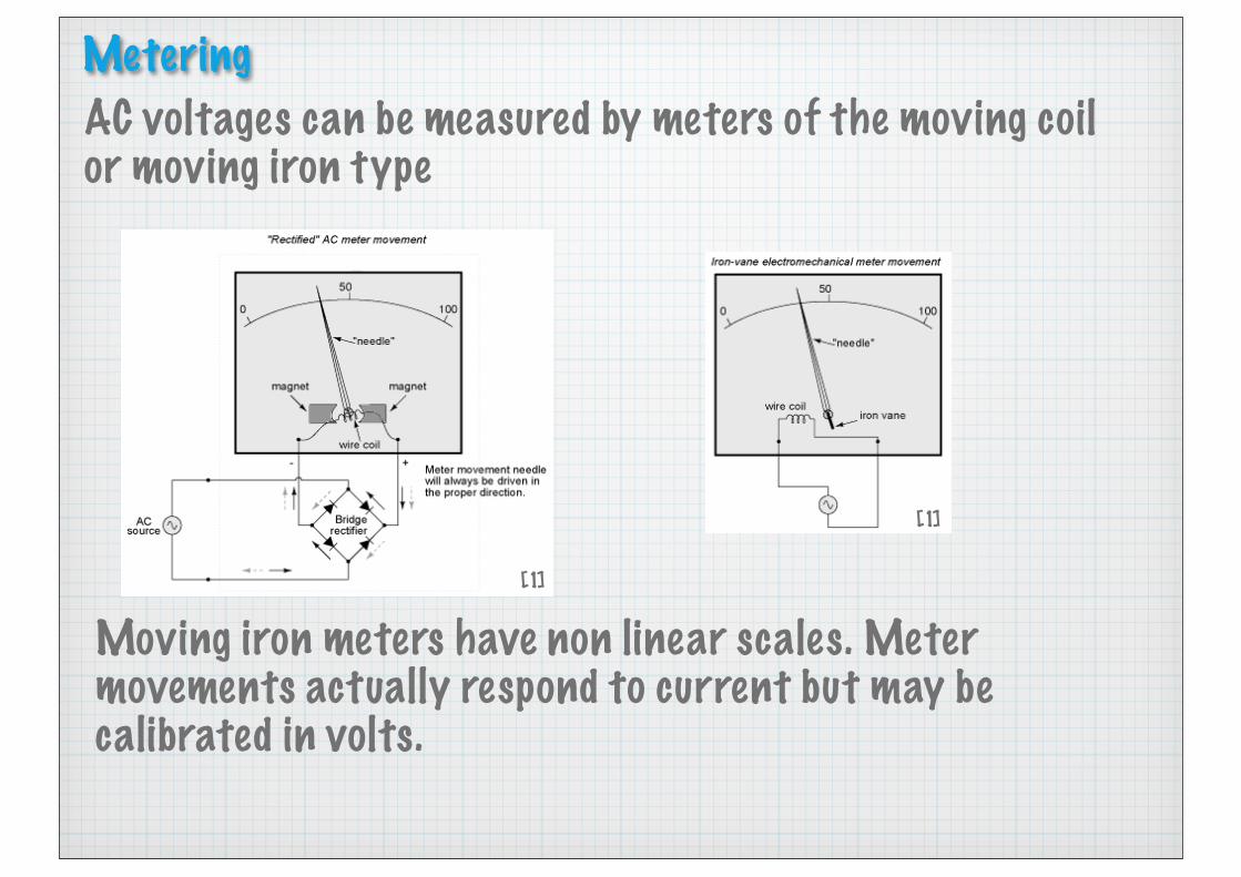
AC voltages can be measured by meters of the moving coil or moving iron type
Moving iron meters have non linear scales. Meter movements actually respond to current but may be calibrated in volts.

Low values of AC current can be measured with a similar meter movement and usually a shunt resistance.
http://www.jamestowndistributors.com/userportal/document.do?docId=126&title=Sizing+a+Shunt+to+a+DC+Ammeter
For a 1 mA meter movement with 50 Ohm impedance we could make it measure 50 A by using a shunt of 0.001 Ohm.

Of course voltage and current can be measured by microprocessor by applying the voltage (or shunt voltage) to an A/D converter.

Current measurements of high currents can be made using current transformers CTs.
http://commons.wikimedia.org/wiki/File:Leistungsschalter-110KV.jpg
Burden resistor (R Ohms)
V = I/Nsec x R
I/Nsec

http://www.conservelec.com.au/software.htm
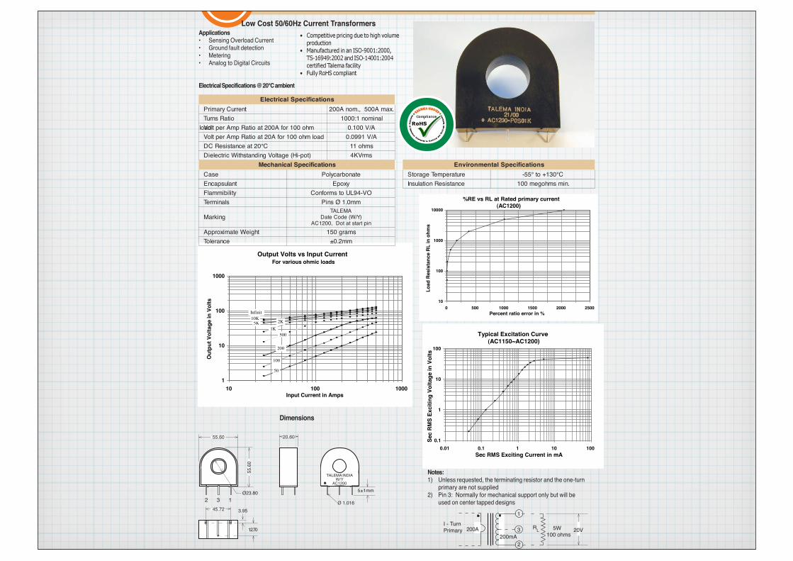
AC1200 • 200 Amp Current Transformer
Low Cost 50/60Hz Current TransformersApplications• Sensing Overload Current• Ground fault detection• Metering• Analog to Digital Circuits
Electrical Specifications @ 20°C ambient
Notes:1) Unless requested, the terminating resistor and the one-turn
primary are not supplied2) Pin 3: Normally for mechanical support only but will be
used on center tapped designs
I - TurnPrimary 5W
100 ohms2
1
20V200A200mA
RL3
0.1
1
10
100
Sec
RMS
Exci
ting
Volta
ge in
Vol
ts
0.01 0.1 1 10 100 Sec RMS Exciting Current in mA
Typical Excitation Curve(AC1150~AC1200)
1
10
100
1000
Out
put V
olta
ge in
Vol
ts
10 100 1000 Input Current in Amps
Output Volts vs Input CurrentFor various ohmic loads
50
100
200
5001K
2K5K10KInfinit
10
100
1000
10000
Load
Res
ista
nce
RL in
ohm
s
0 500 1000 1500 2000 2500 Percent ratio error in %
%RE vs RL at Rated primary current(AC1200)
Dimensions
20.60
5±1mm
TALEMA INDIAW/Y
AC1200
Ø23.802 3 1
55.6
0
55.60
Ø 1.016
12.70
45.72 3.95
snoitacificepSlacirtcelEtnerruCyramirP .xamA005,.monA002
oitaRsnruT lanimon1:0001mho001rofA002taoitaRpmAreptloVdaol A/V001.0
daolmho001rofA02taoitaRpmAreptloV A/V1990.0C°02taecnatsiseRCD smho11
)top-iH(egatloVgnidnatshtiWcirtceleiD smrVK4snoitacificepSlacinahceM snoitacificepSlatnemnorivnE
esaC etanobracyloP erutarepmeTegarotS C°031+ot°55-tnaluspacnE yxopE ecnatsiseRnoitalusnI .nimsmhogem001
ytilibimmalF OV-49LUotsmrofnoCslanimreT mm0.1ØsniP
gnikraMAMELAT
)Y/W(edoCetaDniptratstatoD,0021CA
thgieWetamixorppA smarg051ecnareloT mm2.0±
• Competitive pricing due to high volume
production
• Manufactured in an ISO-9001:2000,
TS-16949:2002 and ISO-14001:2004
certified Talema facility
• Fully RoHS compliant
Germany: Int.+49 89 - 841 00-0 • Ireland: Int.+35 374 - 954 8666 • Czech Rep: Int.+420 377 - 338 351 • India: Int.+91 427 - 244 1325 http://www.talema-nuvotem.com (06-06)CT’s\AC1200


Clamp meter (Tongmeter)
http://www.fluke.com/Fluke/auen/Clamp-Meters/Fluke-336.htm?PID=70327

HV CT
http://electrical-electronics-engineering.blogspot.com.au/2009/12/high-voltage-dry-type-current_273.html
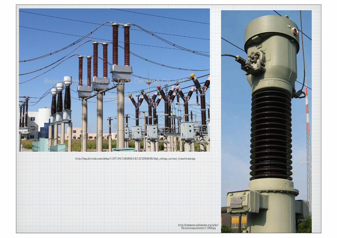
http://img.diytrade.com/cdimg/1157134/12668601/0/1272596836/high_voltage_current_transformer.jpg
http://commons.wikimedia.org/wiki/File:Leistungsschalter-110KV.jpg

What happens if a CT has the secondary open circuited?

Primary transformers PTs can be used to measure high voltages. In conjunction with CTs an apparent power measurement can be made.

Hall effectA hall effect sensor produces a potential perpendicular to the direction of current flow and applied magnetic field in a semiconductor.
http://www.electronics-tutorials.ws/electromagnetism/hall-effect.html
VH = RHIt× B⎛
⎝⎜⎞⎠⎟

http://machinedesign.com/article/sensor-sense-hall-effect-current-sensors-0809
Extremely compact current sensors can be made using this technique. The current through the sensor is normally quite small therefore to make a high current sensor the current to be measured creates the magnetic field.

IP+IP+
IP–IP–
IP
5GND
2
4
1
3ACS712
7
8+5 V
VIOUTVOUT
6FILTER
VCC
CBYP0.1 µF
CF1 nF
Application 1. The ACS712 outputs an analog signal, VOUT . that varies linearly with the uni- or bi-directional AC or DC primary sampled current, IP , within the range specified. CF is recommended for noise management, with values that depend on the application.
ACS712
DescriptionThe Allegro® ACS712 provides economical and precise solutions for AC or DC current sensing in industrial, commercial, and communications systems. The device package allows for easy implementation by the customer. Typical applications include motor control, load detection and management, switch-mode power supplies, and overcurrent fault protection. The device is not intended for automotive applications.
The device consists of a precise, low-offset, linear Hall circuit with a copper conduction path located near the surface of the die. Applied current flowing through this copper conduction path generates a magnetic field which the Hall IC converts into a proportional voltage. Device accuracy is optimized through the close proximity of the magnetic signal to the Hall transducer. A precise, proportional voltage is provided by the low-offset, chopper-stabilized BiCMOS Hall IC, which is programmed for accuracy after packaging.
The output of the device has a positive slope (>VIOUT(Q)) when an increasing current flows through the primary copper conduction path (from pins 1 and 2, to pins 3 and 4), which is the path used for current sampling. The internal resistance of this conductive path is 1.2 m� typical, providing low power loss. The thickness of the copper conductor allows survival of
ACS712-DS, Rev. 13
Features and Benefits� Low-noise analog signal path� Device bandwidth is set via the new FILTER pin� 5 �s output rise time in response to step input current� 80 kHz bandwidth� Total output error 1.5% at TA = 25°C� Small footprint, low-profile SOIC8 package� 1.2 m� internal conductor resistance� 2.1 kVRMS minimum isolation voltage from pins 1-4 to pins 5-8� 5.0 V, single supply operation� 66 to 185 mV/A output sensitivity� Output voltage proportional to AC or DC currents� Factory-trimmed for accuracy� Extremely stable output offset voltage� Nearly zero magnetic hysteresis� Ratiometric output from supply voltage
Fully Integrated, Hall Effect-Based Linear Current Sensor IC with 2.1 kVRMS Isolation and a Low-Resistance Current Conductor
Continued on the next page…
Approximate Scale 1:1
Package: 8 Lead SOIC (suffix LC)
Typical Application
TÜV AmericaCertificate Number:U8V 06 05 54214 010
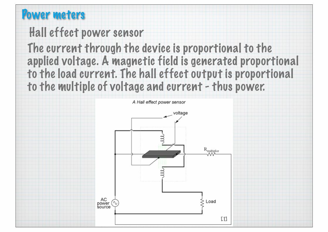
Hall effect power sensorThe current through the device is proportional to the applied voltage. A magnetic field is generated proportional to the load current. The hall effect output is proportional to the multiple of voltage and current - thus power.
[1]
Power meters

“Not only will the output voltage of the Hall effect device be the representation of instantaneous power at any point in time, but it will also be a DC signal! This is because the Hall voltage polarity is dependent upon both the polarity of the magnetic field and the direction of current through the conductor. If both current direction and magnetic field polarity reverses -- as it would every half-cycle of the AC power -- the output voltage polarity will stay the same.
If voltage and current in the power circuit are 90o out of phase (a power factor of zero, meaning no real power delivered to the load), the alternate peaks of Hall device current and magnetic field will never coincide with each other: when one is at its peak, the other will be zero. At those points in time, the Hall output voltage will likewise be zero, being the product (multiplication) of current and magnetic field strength. Between those points in time, the Hall output voltage will fluctuate equally between positive and negative, generating a signal corresponding to the instantaneous absorption and release of power through the reactive load. The net DC output voltage will be zero, indicating zero true power in the circuit.” [1]

Electromechanical meters
How it works - Science and Technology. Marshall Cavendish
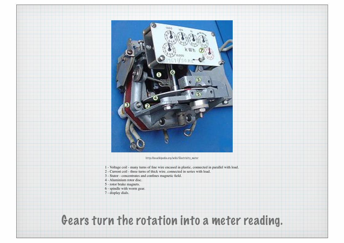
One coil induces flux proportional to voltage into an aluminium disk. Another induces a 90 degree phase shifted flux proportional to current. The rotational torque is proportional to power. A brake magnet keeps the disk stationary when no power is drawn.
http://en.wikipedia.org/wiki/Electricity_meter
Gears turn the rotation into a meter reading.
1 - Voltage coil - many turns of fine wire encased in plastic, connected in parallel with load.2 - Current coil - three turns of thick wire, connected in series with load.3 - Stator - concentrates and confines magnetic field.4 - Aluminium rotor disc.5 - rotor brake magnets.6 - spindle with worm gear.7 - display dials.

Polyphase circuits
[1]

http://en.wikipedia.org/wiki/American_wire_gauge

[1]
What if we doubled the voltage

Split phase
[1]
[1]

3 phase

3 phase alternators

http://en.wikipedia.org/wiki/3-phase_AC

Cable colour codes
The electrical standard in Australia uses the following colours for flexible power cables.
Active Brown (To remember - you end up buried in the brown soil if you touch this one)Neutral Blue
Ground Green and yellow
Fixed wiring in buildings is usually:
Active RedNeutral BlackGround Green and yellow

Active (Live)Neutral
Ground
Sockets are wired with the left pin active or live.
(To remember - LEFT IS LIVE IN A SOCKET)
Active (Live)Neutral
Ground
Remember the pins of a 3 pin plug are reversed when viewed from the pin side. It is still LEFT IS LIVE from the back.