efficient and clean power production: minimizing impacts ... archive/files/merge/vol-45... ·...
TRANSCRIPT

EFFICIENT AND CLEAN POWER PRODUCTION: MINIMIZING
IMPACTS OF INORGANIC COMPONENTS IN COAL AND OTHER FUELS
Steven A. Benson, Christopher J . Zygarlicke, and Everett A. Sondreal
Energy & Environmental Research Center, University of North Dakota
PO Box 9018, Grand Forks, ND 58502-9018
KEYWORDS: solid fuels, combustion, gasification, environmental issues
ABSTRACT
The inorganic components associated with coal and other solid fuels influence the design and operation of power systems. The problems associated with inorganic species include abrasion, corrosion, and erosion of system parts; slag flow in wet-bottom systems; fouling and slagging of heat-transfer surfaces; formation of fine particulate and vapor-phase species that are difficult to collect and can cause adverse environmental effects; plugging of gas-filtering systems; and disposal and utilization of ash residuals. The inorganic components associated with solid fuels consist of major, minor, and traceelements, which occur in a wide range of forms. Forexample, the association of inorganic components in coal depends on rank and depositional environment. Firing solid fuels for power production transforms the inorganic species to gases, liquids, and solids and carries them through the system with the bulk gas flow. The interaction and behavior of the inorganic gases, liquids, and solids in the system are dependent upon system design and operating conditions. Research and development over the past 20 years have provided key insights into the fundamental behavior of major, minor, and trace elements in combustion and gasification systems as well as associated pollution control systems, leading to improvements in the performance and design of conventional and advanced power systems.
INTRODUCTION
The current and future use of solid fuels such as coal, biomass, petroleum coke, municipal solid waste, and paper products is greatly dependent on solving problems related to the combustion behavior of the high-temperature, noncombustible inorganic fraction, or the ash-forming constituents. The abundance and forms of inorganic components associated with these fuels vary widely and can have significant impact on the economic and environmental performance of the power system. The inorganic components are the root cause of many operational and environmental problems in conventional and advanced power systems, which may include abrasion and erosion of equipment; ash deposition and corrosion on heat-transfer and refractory surfaces in boilers and gasifiers; poor slag flow in slagging combustors and gasifiers; emissions of acid rain-forming species; hazardous air pollutant emissions, including precursors to secondary particulate matter formation; and increased requirements for air pollution controls. The literature on ash-related issues is immense. Overviews of ash-related issues and compilations of work by many investigators can be found in the work of Benson ( I , 2), Baxter and Desollar (3), Couch (4). Williamson and Wigley (5). Benson and others (6). Benson (7). Bryers and Vorres (S), and Raask (9, IO). Overviews of the environmental issues such as mercury, traceelements. and particulate matter have been summarized in twospecial issues (1 I , 12). In addition, a review of mercury transformation; behavior, andcontrol was conducted recently (13).
Current and future trends in the use of solid fuels are being and will be driven by economic and environmental factors. Environmental factors have had significant impact on the type of coal utilized by the power industry. The Clean Air Act Amendments (CAAA) of 1990, Toxic Release Inventory (TRI), and an increasedawareness of global warming have made asignificant impact on the diversity of use of solid fuels in the future. The 1990 CAAA identified 189 hazardous air pollutants that are subject to control. Eleven trace elements including antimony, cadmium, lead, nickel, chromium, manganese, selenium, beryllium, cobalt, and mercury are among the 189 toxic substances. Currently, a significant effort is being conducted on mercury measurement and control for codl-fired utility boilers. The TRI now requires electric utility companies to report their annual releases of toxic chemicals. The TRI is a national compilation of releases of more than 600 chemicals designated as toxic by the Environmental Protection Agency (14). As a result of increasedenvironmental pressure, many utilities have switched to low-sulfur coals for compliance with SO, regulations. In addition, the utilization of biomass-derived fuels appears to be on the rise because of concerns over global warming, which may in part be caused by an increase in CO, in the earth’s atmosphere. The combustion of biomass does not increase the overall CO, inventory in the atmosphere. Finally,

deregulation of the utility industry is increasing incentives to fire the cheapest fuels available such as spot-market coals, petroleum coke, waste materials, and biomass.
INORGANIC COMPOSITION OF SOLID FUELS
The association and abundance of major, minor, and trace elements in coal is dependent upon coal rank and depositional environment. The inorganic components in lower-rank subbituminous and lignitic coals are associated with the organic and mineral portions of the coal matrix. The lower-rank Coals contain high levels of oxygen, some of which are in the form of carboxylic acid groups that can BCt as sites for cations such as Ca”, Mg?’, Na+’, K+’, Sr+’, and Ba”. The inorganic components associated with bituminous and anthracite are primarily in the form of discrete minerals. The major mineral groups include quartz, clay minerals, pyrite, and carbonates. The abundance and association Of minerals in coal have been reviewed and published in FuJ1darnenral.s of Coal Combustion for Clean andEfficient Use( 15). The sulfuroxideemissions from powerplants are derivedfromorganic sulfur and mineral forms such as pyrite, gypsum, barite, and others. Air toxic metals can be associated both with organic functional groups and with minerals in coal. Commonly, traceelements in coal are included in the list of 189 toxic substances called out by the 1990 CAAA, for example, antimony, cadmium, lead, nickel, chromium, manganese, selenium, beryllium, cobalt, andmercury. The associations of trace elements in coals are summarized by Swaine (16). Finkelman (17), and Benson and others (18). .
Petroleum Coke
The inorganic components associated with petroleum coke materials have been summarized by Bryers (19). Petroleum contains a low level of ash-forming species ranging from 0.5 up to 2.5 wt%. The inorganic components consist mainly of nickel, vanadium, sulfur, silicon, aluminum, and minor amounts of iron, sodium, and potassium. The key elements S, V, Fe, and Ni are organically associated as porphyrin complexes.
Biomass
The inorganic composition of biomass fuels has been review by Jenkins and others (20). The inorganic components associated with biomass coals include Si, AI, K, Na, S, CI, P, Ca, Mg, and Fe. These elements occur at different levels in various types of biomass fuel, including agricultural products (manure, hulls, pits), wood, herbaceous materials (grasses, straws, leaves), and a wide range of waste materials (e.g., municipal solid waste, sewage sludge, and plastics). Most of the inorganic components in plants are associated with the organic matrix, as in some lignitic and subbituminous coals. Biomass-type fuels alsocause slagging and fouling problems that are similarto those produced from low-rank coals (6.21-23). For example, in low-rank coals, alkali and alkaline-earth elements interact and combine with silicates to form low-temperature melt phases that melt at temperatures as low as 700”C, as well as sulfate phases that can have melting points as low as 650°C. Baxterand others (24) reported the formation of sulfate-, silicate-, chloride-, and carbonate-type deposits when biomass-type fuels were fired.
Trace elements are also of concern in biomass utilization. In Austria, Obernberger (25) reported concerns regarding the levels of Mn, Cu. An, Co, Mo, Ni, Cr, Pb, V, and Hg. The ash produced from biomass combustion systems is used as fertilizer, and the levels of selected trace elements must be below regulatory limits. Researchers in Austria have developed a method to fractionate the heavy metals.
BEHAVIOR IN CONVERSION AND ENVIRONMENTAL CONTROL SYSTEMS
Major, minor, and trace inorganic components associated with fossil and biomass fuels undergo a complex series of chemical and physical transformations in combustion and conversion devices, air pollution control systems, and in the ecosystem (26). These transformations are illustrated in Figure 1. The primary factors that influence the fate of the inorganic species include:
The important operating conditions within the conversion system, such as oxygen stoichiometries andgas composition in general, flame and subsequent flue gas temperatures, particle residence times, and heating and cooling rates.
The chemical composition and physical characteristics of inorganic components in the fuel that influence their reactivity and volatility during combustion or gasification.
89

The transformations of inorganic components occurring during combustion/gasification and gas cooling that result in the formation of various inorganic vapor, liquid. and solid phases, depending on fuel composition and conversion conditions. These transformations typically result i n the formation of a bimodal (modes at -0.1 and -12 pm) particle-size distribution of ash particles over a wide range of chemical compositions. Some mineral species in fuels may remain in their original form through theconversion andenvironmenlal control system. Other elements such as mercury may be released in their vapor state and tend to remain in the gas phase as an emission.
The state (vapor, liquid, and solid) and physical properties (size, density, viscosity, and surface tension) of the intermediate ash species as a function of temperature, atmosphere, and residence time. The more volatile elements-which include the alkali metals (Na and K) and certain trace elements such as As, S e , Pb, Cd, Sb, Hg, and others-are enriched in the smaller size fractions of ash and in the vapor-phase portion of the flue gas stream. This distribution directly impacts fate of the inorganic intermediate species in the conversion and environmental control system.
Ash deposition, corrosion, and erosion on heat-transfer surfaces depending on gas composition; condensed melt phases; ash particle size; and aerodynamicdfluid dynamic behavior.
The progressive accumulation of intermediate ash materials that decrease heat transfer and increase fireside temperatures in the system. The characteristics of the liquid-phase components in deposits, as determined by their chemical composition are critical to deposit strength and growth development.
The capture of the inorganic intermediate material in air pollution control devices is dependent upon the form of the material and the mode of collection. In electrostatic precipitation, the collection efficiency of the particles is related to the resistivity of the ash and the particle size. Collection of ash in a baghouse is related to the size of the ash particles and the cohesive properties of the ash dust cake. The ash dust cake can capture both particulate and gas-phase components. Scrubbers are designed to capture vapor-phase species such as SO, utilizing CaO or other reagents. The speciation of the inorganic elements, system conditions, sorbent composition and size, and residence time all influence the reaction of vapor-phase inorganic materials with dry and wet sorbents.
Hot-gas cleanup systems for advanced combustion and gasification systems utilize metal and ceramic-type filters. These filters must remove the particulate material to levels that can be tolerated by a turbine or fuel cell. Ceramic candle filters that are just beginning to be used in full-scale demonstration projects experience failures from a combination of adverse factors, including cyclic thermal stress, ash deposition and surface blinding, and corrosion of ceramic materials by alkalies, chlorides, trace elements, and molten slag phases.
DIRECTIONS FOR THE FUTURE
Future high-performance power systems that utilizc coal, biomass, and oil and petroleum coke feedstocks must consider all of the forgoing impacts of inorganic components on system performance and emissions. The key is to match fuel quality with system design and operating conditions. Environmental drivers such as global warming, hazardous air pollutants, regional haze, and particle matter will have a major influence on future fuel sources, power system design, and operating conditions. In order to minimize environmental impact, control cost, and improve efficiency, it will be necessary to identify synergistic relationships for a variety of fuel blends, such as coal and biomass, under a wide range of design and operating conditions.
A vision for power systems for the next century is being developed by the U.S. Department of Energy Office of Fossil Energy (27). The Vision 21 power system is designed to coproduce electricity, heat, transportation fuels, and chemicals with little or no air pollution. solid wastes, or carbon dioxide emissions. The system would be fuel-flexible, thereby allowing for firing of a single fuel or a combination of fuels consisting of coal, natural gas, petroleum coke, and biomass. The energy plant comprises several modules, including combustiodgasification, separatiodconversion, gas cleanup, CO, sequestration, power, fuels/ products, and steam and cogeneration. This scenario of how next-generation power systems will evolve must account for the effects of the noncombustible or inorganic fractions of the fuel, which greatly impact conversion and environmental control system components.
90

1
I
REFERENCES
1. Ash Chemistry: Phase Relationships in Ashes and Slags. Special Issue of Fuel Processing Technology; Benson, S.A., Ed.; Elsevier Science Publishers, July 1998, Vol. 56, Nos. 1-2, 168 p.
Ash Chemistry in Fossil Fuel Processes. Special Issue of Fuel Processing Technology; Benson. S.A.; Ed.; Elsevier Science Publishers, Sept. 1995, Vol. 44, Nos. 1-3, 288 p.
3. BaXter, L.; DeSollar, R., Eds. Applications of Advanced Technology to Ash-Related Problems in Boi1er.s; Plenum Press: New York, 1996.
4. Couch, G. Understanding Slagging and Fouling During Combustion; E A Coal Research Report, 1994.
5 . Williamson, J.; Wigley, F., Eds. The Impact of Ash Deposition on Coal FiredPlants: Proceedings of the Engineering Foundation Conference; Taylor & Francis: London, 1994.
6. Benson, S.A.; Jones, M.L.; Harb, J.N. Ash Formation and Deposition-Chapter 4. In: Fundamentals of Coal Combustion for Clean and Ejficient Use; Smoot, L.D., Ed.; Elsevier: Amsterdam, 1993, pp 299-373.
2.
7. Benson, S.A.. Ed. Inorganic Transformations and Ash Deposition During Combustion. American Societyof Mechanical Engineers for the Engineering Foundation: New York, 1992.
8. Bryers, R.W.; Vorres, K.S.. Eds. Proceedings of the Engineering Foundation Conference on Mineral Matter and Ash Deposition from Coak Feb 22-26, 1988, Santa Barbara, CA; Unit Engineering Trustees Inc., 1990.
9. Raask, E. Erosion Wear in Coal Utility Boilers; Hemisphere: Washington, 1988
10. Raask, E. Mineral Impurities in Caul Combustion; Hemisphere: Washington, 1985
I 1. Trace Element Transformations in Coal Fired Power Systems. Special Issue of Fuel Processing Technology; Benson, S.A., Steadman, E.N., Mehta, A,, Schmidt, C., Eds.; Elsevier Science Publishers: Amsterdam, Aug 1994; Vol. 39, Nos. 1-3.492 p.
12. AirQuality: Mercury,Trace Elements, and Particulate Matter. Special Issueof Fuelprocessing Technology; Benson, S.A., Brown, T.D., Eds.; Elsevier Science Publishers, in preparation, publish date in 1999.
13. Brown, T.D.; Smith, D.N.; Hargis, R.A.; O’Dowd, W.J. Critical Review: Mercury Measurement and Its Control: What We Know, Have Learned, and Need to Further Investigate. J. Air & Waste Marlage. Assoc., June 1999, pp 1-97.
14. Rubin, E.S.; Berkenpas, M.B. A National Analysis of Toxic Releases from Electric Power Plants. EM, Air and Waste Management, Oct 1999, pp 3 1-37.
15. Smoot, D.L. Fundamentals of Coal Combustioil f o r Clean and Ejficient Use; Elsevier: Amsterdam. 1993.
16. Swaine, D.J. Trace Elements in Coal; Buttenvonhs: Boston, 1990.
17. Finkelman, R.B. Modes of Occurrence of Potentially Hazardous Elements in Coal: Levels of Confidence. Fuel Processing Technology 1994 39,21-34.
18. Benson, S.A.; Pavlish, J.P.; Zygarlicke, C.J. Trace Elements in Low-Rank Coals. In Proceedings ofthe 15th Annual International Pittsburgh Coal Conference; Pittsburgh, PA, Sept 14-18, 1998.
19. Bryers, R.W. Utilization of Petroleum Coke and Petroleum Coke/Coal Blends as a Means of Steam Raising. In Coal Blending arid Switching of Low-SulJur Western Coals; Bryers, R.W., Harding, N.S., Eds.; American Society of Mechanical Engineers: New York, 1994.
20. Jenkins, B.M.; Baxter, L.L.; Miles, T.R. Jr; Miles, T.R. Combustion of Biomass, Fuel Processing Technology, 1998 54, 1746.
91

21. Jones, M.L.; Benson, S.A. An Overview of FoulinglSlagging with Western Coals. Presented at the EPRI-Sponsored Conference on Effects of Coal Quality on Power Plants, Atlanta, GA, Oct 13-15, 1987; 22 p.
22. Erickson, T.A.; Ludlow, D.K.; Benson, S.A. Interaction of Sodium, Sulfur, and Silica During Coal Combustion. Energy & Fuels 1991.5 (4), 539-547.
: 23. McCollor, D.P.; Zygarlicke, C.J.; Oakley, R. Assessment of Cofiring Paper Sludge-Plastic
Pellets with Bituminous Coal. In Proceedingsofthe 16thAnnuallnremarional Pirtsburgh Coal Conference; Pittsburgh, PA, Oct 11-15, 1999, 15 p.
24. Baxter, L.L.; Miles,T.R. Jr; Mi1es.T.R.; Jenkins, B.M.; Mi1ne.T.; Dayton, D.; Bryers, R.W.; Oden, L.L. The Behavior of Inorganic Material in Biomass-Fired Power Boilers: Field and Laboratory Experience. Fuel Processing Technology 1998 54,47-78.
B 25. Obernberger, I., Ed. Ashes and Particulate Emissions from Biomass Combustion; Series
Thermal Biomass Utilization, Vol. 3, Technical University of Graz, Institute of Chemical Engineering, Oct 1998.
26. Benson, S.A.; Sondreal, E.A. Ash-Related Issues During Combustion and Gasification. Presented as Keynote Address to the Engineering Foundation Conference on Impact of Mineral Impurities in Solid Fuel Combustion, Keauhou-Kona, HI, Nov 2-7,1997.
21. Coal and Power Systems, Strategic Plan and Multiyear Plans; Office of Fossil Energy, US . Department of Energy, Washington, DC, Jan 1999.
FIGURES
EERCSBIOIS CDR por-Phase Species Reactions HgO. Hg'. HgCI, Se. As .&E2
-Solid Reanions -Sorbent Hg' Hgot HgCI' Hg(Noa'
CI , co
Homogeneous Condensation
.<& -FlyAsh c 1 pm -Small Particles
0..* Char, Mineral Fragmen
Na. K. SO:. CI; S . As. Ca. Pb. Se, Sb
Heterogeneous CondensaOon
Solid and Liquid Particles. SiO,, AI,Si,O,, FeO .. .- Fe,O.. Fe,O,. CaO. MgO : -,'. .' +Complexes, (i.0.. CaAlSiiO.) -FlyAsh>lvm
.e.
3::. . .. Surface Enrichment
Na. K, SO;. As, Ca. Pb, Se Cr, NI, Mn Battorn Ash
Radiant Section - Convective Pass - Air Pollution Control System
H20
Figure 1. Examples of possible inorganic transformations during conversion
92
TRENDS IN PREDICTING AND CONTROLLING EMISSIONS FROM COAL FIRED BOILERS
Christina M. Lee', Kevin A. Davis', Michael P. Heap' 'Reaction Engineering International
77 West 200 South Suite#210 Salt Lake City, UT 84101
Adel F. Sarofirn', Eric G. Eddings* *Department of Chemical and Fuels Engineering, University of Utah
1495 East 100 South 206 Kennecott Research Center Salt Lake City, UT 841 12-1 114
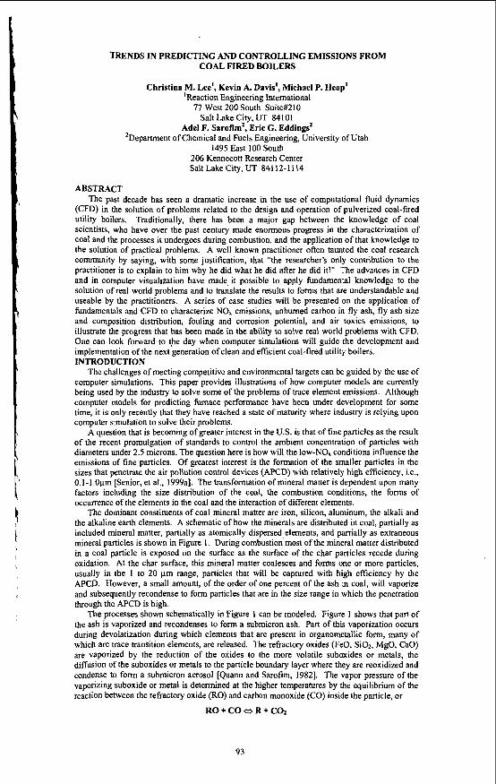
ABSTRACT The past decade has seen a dramatic increase in the use of computational fluid dynamics
(CFD) in the solution of problems related to the design and operation of pulverized coal-fired utility boilers. Traditionally, there has been a major gap between the knowledge of coal scientists, who have over the past century made enormous progress in the characterization of coal and the processes it undergoes during combustion, and the application of that knowledge to the solution of practical problems. A well known practitioner often taunted the coal research community by saying, with some justification, that "the researcher's only contribution to the practitioner is to explain to him why he did what he did after he did it!" The advances in CFD and in computer visualization have made it possible to apply fundamental knowledge to the solution of real world problems and to translate the results to forms that are understandable and useable by the practitioners. A series of case studies will be presented on the application of fundamentals and CFD to characterize NO. emissions, unburned carbon in fly ash, fly ash size and composition distribution, fouling and corrosion potential, and air toxics emissions, to illustrate the progress that has been made in the ability to solve real world problems with CFD. One can look forward to the day when computer simulations will guide the development and implementation of the next generation of clean and efficient coal-fired utility boilers. INTRODUCTION
The challenges of meeting competitive and environmental targets can be guided by the use of computer simulations. This paper provides illustrations of how computer models are currently being used by the industry to solve some of the problems of trace element emissions. Although computer models for predicting fimace performance have been under development for some time, it is only recently that they have reached a state of maturity where industry is relying upon computer simulation to solve their problems.
A question that is becoming of greater interest in the U.S. is that of fine particles as the result of the recent promulgation of standards to control the ambient concentration of particles with diameters under 2.5 microns. The question here is how will the low-NO, conditions influence the emissions of fine particles. Of greatest interest is the formation of the smaller particles in the sizes that penetrate the air pollution control devices (APCD) with relatively high efficiency, i t . , 0.1-1.0pm [Senior, et al., 1999al. The transformation of mineral matter is dependent upon many factors including the size distribution of the coal, the combustion conditions, the forms of Occurrence of the elements in the coal and the interaction of different elements.
The dominant constituents of coal mineral matter are iron, silicon, aluminum, the alkali and the alkaline earth elements. A schematic of how the minerals are distributed in coal, partially as included mineral matter, partially as atomically dispersed elements, and partially as extraneous mineral particles is shown in Figure 1. During combustion most of the mineral matter distributed in a coal particle is exposed on the surface as the surface of the char particles recede during oxidation. At the char surface, this mineral matter coalesces and forms one or more particles, usually in the 1 to 20 pm range, particles that will be captured with high efficiency by the APCD. However, a small amount, of the order of one percent of the ash in coal, will vaporize and subsequently recondense to form particles that are in the size range in which the penetration through the APCD is high.
The processes shown schematically in Figure 1 can be modeled. Figure 1 shows that part of the ash is vaporized and recondenses to form a submicron ash. Part of this vaporization occurs during devolatization during which elements that are present in organometallic form, many of which are trace transition elements, are released. The refractory oxides (FeO, SO2, MgO, CaO) are vaporized by the reduction of the oxides to the more volatile suboxides or metals, the diffusion of the suboxides or metals to the particle boundary layer where they are reoxidized and condense to form a submicron aerosol [Quann and Sarofim, 19821. The vapor pressure of the vaporizing suboxide or metal is determined at the higher temperatures by the equilibrium of the reaction between the refractory oxide (RO) and carbon monoxide (CO) inside the particle, or
RO + CO ~1 R + COz
93
The mass transfer from the surfaces of the mineral inclusions to the surface of the char particle determines the vaporization rate. The size of the submicron particles may be calculated from the mass vaporized using well-established theory on aerosol dynamics. In addition, as depicted schematically in Figure 1, the more volatile salts of the alkali metals and the volatile trace metals will vaporize. These will condense downstream of the combustion zone at points where the combustion products have cooled down to their condensation temperatures. They will deposit on the surfaces of existing particles, in a manner calculable from mass-transfer-limited condensation.
AS mentioned previously, computational fluid dynamics (CFD) tools have been developed to the point where many practical problems of industrial interest can be solved. For coal-fired utility boilers, the problems are typically related to evaluating the viability of a modem retrofit, such as a low NOx firing system, and evaluating the potential for adverse side effects such as increased levels of unburned carbon, additional depositiodfouling problems, and the potential for increased waterwall wastage. A case study will be presented here demonstrating how such CFD tools can be used to address a problem related to mineral matter transformations under low NO, conditions. Because of the dependence of the vaporization of mineral constituents on temperature and local equivalence ratio, it is expected that staging for NO, control will change the formation and emissions of fine particles. The temperature-oxidation history for individual particles provides the information needed for the calculations. Due to space limitations this paper will focus on presenting the transformation of mineral matter in ash to a sub-micron fume that transports air toxics. METHOD
The development of a model for the vaporization ash was a two-phase process. Phase 1, the initial development of the model, is used to verify experimental data for single particle combustion. The second phase requires minor modifications such that multiple particles can be evaluated. Particle iterations such as this are common in advanced CFD codes used for modeling coal-fired boilers.
The development of the first phase of the model was necessary to verify this computational model with experimentally derived results. In this scenario, a particle temperature history was necessary for running the model. Since this data was not available from the experimental data, the information needed to be generated. This was done using coal properties and combustion conditions. This information was fed into a computer code, which calculates carbon bumout kinetics. These calculations provide the necessary information including particle size, temperature, and residence time. From this information, the vaporization of elemental ash inclusions can be determined.
The experimental results for ash'vaporization were performed by Quann and have been documented in the literature (Quann and Sarofim, 1982). The model was run for 14 different coals used in the experimental analysis. Figures 2 and 3 summarize the results for the model cases as normalized against the vaporization determined by Quann. ' The code was used in calculating the vaporization for Si02, AI@,, FeO, CaO, and MgO. However, due to space limitations the results are given only for Si02 and CaO.
As can be seen from Figures 2 and 3, the fourteen coals used in the model verification are referred to by their respective Penn State Coal Database number followed by the type, bituminous (B), subbituminous (SB), or lignite (L). It should also be noted that the vaporization when compared with Quam will vary depending on coal type and mineral inclusion size. Since the mineral inclusion size was not known for Quann's data, several cases were run. Agreement with Quam's data is observed for silica for the inclusion sizes of IO to 20 pm, and for calcium for inclusion sizes of greater than 20 pn for the bituminous coals and less than 5 l m for the lignites. As will be discussed in the next section, coal 503-B will be used in actual multi-particle calculations. The values for the optimal inclusion sizes for each component for this coal are summarized in Table 1. The optimal inclusion size can be defined as those that are exactly verified with the Quann data. RESULTS
The second phase of the vaporization had to be modified slightly to account for multiple particle iterations as performed in the CFD code. In addition, the code was run with and without the effects of COz. In the comparison with the experimental results, the COz was not an issue, but in an actual furnace case as will be shown, the CO2 has a noticeable contribution.
The computational tools used in this study were developed by Reaction Engineering International (REI) to address a wide range of problems involved in the operation and design and of many combustion systems including utility boilers, pyrolysis furnaces, gas turbine combustors, rotary kilns, waste incinerators and smelting cyclones. The current models simulate both reacting and non-reacting flow of gases and particles, including gaseous diffusion flames, pulverized-coal flames, liquid sprays, coal slurries, injected sorbents, and other oxidatiodreduction systems. Emphasis has been placed on simulating coal combustion and pollutant formation. This three dimensional, two phase reacting flow code (GLACIER) includes several capabilities necessary. for accurate simulation of coal-fired boilers. These capabilities include turbulent particle transport with full coupling of particle and gas-phase mass and
94

momentum; coal reaction processes such as devolatilization, char oxidation and gas-particle interchange; NO, formationheduction chemistry; particle convection and radiation with absorption, emission and anisotropic scattering; full coupling of gas-particle energy exchange; and ash deposition. In addition, boiler-side watenvall and radiant panel surface temperatures can be predicted as part of the computation, given a backside (i.e., steam) temperature and surface resistance (from the deposit thickness and thermal conductivity, for example). As it applies to this paper, the vaporization model is actually a post-processor to be used in conjunction with the GLACIER s o h a r e results.
The unit studied is a 500 Mw opposed wall-fired boiler with twenty-four burners. Five wingwalls come in from the front wall. Prior to low-NOx retrofit, the unit included Foster Wheeler’s Intervane burners. During the retrofit, these burners were replaced by Foster Wheeler’s Controlled-Flow/Split-Flame (CF/SF) burner. In addition, an advanced overfire air (AOFA) system was installed. This consists of an independent windbox for improved penetratiodcontrol of injection through eight directly opposed ports above each column of burners, and four underfire air ports at the level of the bottom burner row near the sidewalls.
As mentioned previously, the COz was not an issue with the single particle model. However, under normal operating conditions, the C02 in the furnace plays a significant role. Figures 4 and 5 illustrate the cumulative vaporization for pre- and post-retrofit conditions accounting for effects due to C02 and neglecting the role of C02 respectively.
Since C02 is an issue which cannot be neglected it has been included in the current model for accurate calculation of the ash vaporization. Figures 6 and 7 illustrate the individual burner contribution to the total amount of ash vaporized. The symmetry plane has been identified, which is used in modeling the furnace in GLACIER. Also, the front and rear walls have been identified for both the pre- (Figure 6) and post-retrofit (Figure 7) cases. DISCUSSION AND CONCLUSIONS
From these results it is evident that the modeling of ash vaporization is feasible. Additionally, it is apparent that the inclusion of CO1 in the model is a necessary component. The presence of C02 ultimately suppresses the vaporization of ash as shown in Figures 4 and 5. Another aspect that is interesting to note is the variation in the vaporization between the front and rear wall. In the pre-retrofit case (Figure 6), the ash vaporization contribution from the.front wall is 72 percent while the rear wall contributes only 28 percent. In the post-retrofit case, the contribution is more evenly distributed with 57 percent of the ash vaporized coming from the front wall and 43 percent from the rear. The next step in developing this vaporization model is to determine the particle size distribution of the vaporized ash. REFERENCES Davis, K.A., Valentine, J.R., Eddings, E.G., Heap, M.P., Hurt, H.R.,.Hardman, R., and Gringas,
N., “Advanced Prediction of Unburned Carbon Levels in Two Utility Boilers Retrofitted for In-Furnace NO, Reduction”, Third Conference on Unburned Carbon in Utility Fly Ash, Federal Energy Technology Center (1997).
Eddings, E. G., K.A. Davis, M.P. Heap, J.R. Valentine, A. Facchiano, R. Hardman, N. Grigas, “Effect of Low NO, Firing Conditions on Increased Carbon-in-Ash and Water-Wall Corrosion Rates,” proceedings of the EPRI/EPA/DOE Mega Symposium on NO,/SO,/Air Toxics, Washington, D.C., Aug. 25-29, 1997.
McElroy, M.W., Carr, R.C., Ensor, D.S., and Markowski, G.R., “Size distribution of fine particles from coal combustion,’’ Science, 215: 13-19 (1981).
Mohr, M., Ylatalo, S., Klippel, N., Kauppinen, E.I., Riccius, O., and Burtscher, H., “Submicron fly ash penetration through electrostatic precipitators at two coal power plants,” Aerosol Sci. Tech., 24: 191-204 (1996).
Neville, M., Quann, R.J., Haynes, B.S., and Sarofim, A.F., “Vaporization and Condensation of Mineral Matter during Pulverized Coal Combustion”, Eighteenth Symposium (International) on Combustion, p. 97, The Combustion Institute, Pittsburgh, PA (1980).
Quann, R., and Sarofim, A.F., “Vaporization of Refractory Oxides during Pulverized Coal Combustion”, Nineteenth Symposium (International) on Combustion, pp. 1429-1440, The Combustion Institute, Pittsburgh, PA (1982).
Senior, C.L., Helble, J.J., and Sarofim, A.F., “Emissions of Mercury, Trace Elements, and Fine Particles from Stationaly Combustion Sources”, Submitted to Fuel Processing Technology (1999a).
Senior, C. L., Helble, J. J., and Sarofim, A. F., “Emissions of Mercury, Trace Elements, and Fine Particles from Stationary Combustion Sources”, to be published in Fuel Processing Technology, 1999b.
Wilemski, G., Srinisvasachar, S., and Sarofirn, A. F., “Modeling of Mineral Matter Redistribution and Ash Formation in Pulveszed Coal Combustion”, in Inorganic Transformations and Ash Deposition During Combustion, Ed. S. A. Benson, Engineering Foundation, ASME, 1992, pages 542-564.
Ylatalo, S.I., and Hautanen, J., “Electrostatic precipitator penetration function for pulverized coal combustion,” Aerosol Sci. Tech., 29,17-30 (1998).
95

PULVEWEDCOM CHAR PARTICLE *SH TRANSFORMATION BEHAVIOR MECHANISMS wina.ew#)
k uEcRe*smo TEMPERANRE
Figure 1: Schematic of Mineral Matter Transformation During Pulverized Coal Combustion.
0 . 1
Figure 2: Si02 experimental results versus vaporization model.
I D M
I M l
IOErn , , , , , , I+*---lC -a%-*
I I I I ' 8 1 " m m m m m m m m m m
lo€-
y s & g ! j w - e a a p g g R 0 . 1
Figure 3: CaO experimental results versus vaporization model.
Figure 4: Cumulative vaporization for pre- and post-retrofit cases with CO2 effect.
96

I Figure 5: Cumulative vaporization for pre- and post-retrofit cases without COz effect.
Fmnt Wdl RcarWdl
synmrrry P k symmy P h c
Figure 6: Pre-retrofit burner contribution to ash vaporization with COz effects.
Front Wall Rcar wall
Figure 7: Post-retrofit burner contribution to ash vaporization with COz effects.
Table 1: Optimal inclusion sizes for each ash component for coal 503-B.
Optimal Inclusion Size (microns) Component
Si02 13 A1203 2 FeO 30 CaO 21
MgO 31
91

IGCC Technical Status, Trends and Future Improvements
ProjectLacation Gasificatlon MW Technology
, Wabash River, Destec 262 Indiana, USA
Neville A. H. Holt - EPRI
Presented at the American Chemical Society Meeting San Francisco, CA '
Much 26-3 1,2000
Introduction
Coal -based IGCC plants have been developed to commercial size over the past two decades. They have only been built as demonstration plants but are operating as commercial units. These units have now accumulated several years of operating experience and have shown that an IGCC plant can meet extremely stringent air emission standards while also achieving high plant efficiencies. The main barriers to the widespread adoption of IGCC technologies are: (1) demonstration of high availability, at least equal to existing pulverized coal (F'C) plants; and (2) capital cost reduction to compete with state-of-the-art PC plants and natural gas-based combined cycles.
Current Status
Three coal-based, commercial-sized (but partially government-funded) IGCC demonstration plant projects are currently operating in the U.S and two in Europe, as summarized in Table 1. The following discussion provides a brief summary of the operational experience to date at these five sites.
Startup Date
10/95
Tampa Elecbic Company, Texaco Florida, USA
SEPDemkolec, Shell Buggenum, The Netherlands
-1 Early 1994
12/97 on coal u The three ongoing US IGCC projects are all based on different gasification technologies and illustrate different application opportunities. All three plants are based on General Electric 'F' gas turbines with turbine inlet temperatures of about 1260°C (2300°F) and equipped with multiple can combustors. The European IGCC projects are both based on Siemens gas turbines equipped with dual silo combustion chambers.
The Pifion Pine and ELCOGAS projects have seen limited operations to date, but both the GE 6FA at Pifion Pine and the Siemens V 94.3 at ELCOGAS have been running very well on natural gas at their design outputs. Although only extended multi-year operations can really test the durability of gas turbines in an IGCC application, the results to date from the projects with the GE F-class gas turbines are very encouraging.
98

!
Project
Gas Turbine Output, MW .
Table 2 presents the major component and overall design performance of these plants, and compares these design values with the operational results achieved to date.
Both the Texaco gasifier at Tampa and the Destec gasifier at Wabash River have demonstrated that they can supply sufficient syngas to fully fuel their combustion turbines. At Tampa, fouling downstream of the gasifier and corrosion in the lower gas temperature range of 250-3OO0C have been the main causes of outages to date. The developers and plant operators are addressing these problems, but in the meantime the plant continues to perform well, albeit at lower than design efficiency. At Wabash River, the main remaining problem area seems to be the dry gas filter, where corrosion and blinding of the metallic candles continue to occur. The most recent operations at these sites are encouraging and show considerable progress, with both projects experiencing long runs and higher availability.
The SEPlDemkolec (Buggenum) project started operations in early 1994. The tight integration has led to some operational sensitivities and complexities, leading SEP to recommend only partial integration for future installations. This recommendation agrees with EPIU's general analysis of the merits of various degrees of integration, although the optimum performancdoperability trade-off depends on the specific characteristics of the gas turbine and its compressor. The ASUs at Wabash and Tampa are supplied by their own compressors, so this problem does not arise.
The main problem encountered in the early years of operation at the Buggenum plant (also later encountered at Puertollano) has been combustion-induced vibrations and overheating in the gas turbine combustors. Design changes made in early 1997 have markedly improved the vibration problem, and since that time several long tuns have been conducted, with an availability of over 80% in each quarter since the third quarter of 1997 (with the exception ofthe second quarters when the required annual inspection is conducted. In the third and fourth quarters of 1998, the Gasification Island was in continuous operation for over 2000 hours. The Shell gasifier has generally performed well and has achieved its design cold gas efficiency.
Wabash River Tampa Buggenum
192 (192) 192(192) 155 (155)
Steam Turbine Output, MW
Auxiliary Power Consumption, MW
Net Power Output, MW
105 (98) 121 (125) 128 (128)
35.4 (36) 63 (66) 31 (31)
261.6 (252) 250 (250) 252 (252)
Net Plant Heat Rate, kJkWh LHV Basis
Net Plant Efficiency, % LHV Basis
1998 IGCC Operating Hours
I 1998 IGCC On-stream Factor, % I 59 161 I 5 6 I
9177 (8708)" 8739 (9244)*** 8373 (8373)
39.2 (41.2)" 41.2 (38.9)*** 43.0 (43.0)
5139 5328 4939
\
Total IGCC Operating Hours Through December I998
10,393 10,010 13,768
99

The successful scale-up from the 225-to~es/day gasifier at Houston (SCGP-I operated 1987-91) to the 2000 tonnedday unit at Buggenum has been amply demonstrated. The raw gas from a dry-coal-fed gasifier such as Shell has lower water content than the sluny-fed gasifiers of Texaco and Destec. Because of this, dew point corrosion in the lower temperature ranges is less likely to occur and, consequently, has not been a problem at Buggenum.
Both the Wabash River and Buggenum plants have met their overall IGCC design efficiencies. However, Tampa has experienced lower-than-design overall efficiency chiefly due to lower carbon conversion and removal of the gadgas exchangers from service (to prevent fouling and corrosion).
In summary, these demonstration plants show that IGCC systems can provide power at higher efficiency than PC plants, with significantly lower air emissions and a more benign solid by-product. While the reliability/availability of these units has improved since they were first brought on line, they are not yet operating at commercially acceptable availability levels (only 5 6 4 1 % in 1998). The developers and government sponsors of these demonstration projects understand this concern and are addressing it through continuing engineering efforts. Based on past experience in the development of new technologies, and assuming continued support by the various government and private parties involved, it is reasonable to expect that the remaining problems will be solved within the next five years.
Market Trends
A number of IGCC plants (many of 500 MW) will be commissioned over the next three years based on the use of petroleum residuals and located adjacent to large petroleum refineries. The shrinking market for high sulfur fuel oil and the impact of tightening fuel specifications and new environmental legislation is the impetus behind these projects. Most of these projects have multiple co-products, typically power, steam and hydrogen for the refinery plus sale of power to the grid or other nearby industrial customers. The projects in Europe are mostly based on heavy oil while the majority of the U.S. projects are based on low value petroleum coke. The experience gained from these projects should aid in reducing the capital cost of IGCC equipment and in providing greater confidence in the reliable operation of this technology.
IGCC plants can meet extremely strict environmental and emission standards and may be applicable to particular locations that have such requirements. If emissions including C02 were ever subject to externality charges or taxes this would make IGCC a more attractive technology. Several studies have shown that if CO~removal from fossil- based power plants is ever required for subsequent disposal, use or sequestration, that it would be much less costly to remove the CO2 from syngas under pressure prior to combustion rather than removal from the huge volumes of stack gases after combustion at atmospheric pressure. The absorption process is driven by partial pressure and the size of vessels is much reduced under pressure.
100

Table 3. IGCC Plants based on Petroleum Residuals
Repsol/lberdrola/Texaco - Heavy oils Texaco I7-800/Steam/H2 2003 Bilbao, Spain
Exxon Singapore Ethylene cracker Texaco 16O/CO + H2 2002 bottoms
Future Technical Improvements
The larger higher eficiency G and H gas turbines, with firing temperatures of -15OO0C (2732°F) are now entering commercial service based on natural gas. When applied to IGCC plants these turbines will provide further gains in efficiency and reductions in capital cost through economy of scale. The U S . DOE through its Vision 21 initiative has a comprehensive R&D program with gasification as a key core technology. Improvements in all aspects of the basic IGCC flowsheet are being addressed including ion transpott membranes for improved ASU’s, more flexible fluid bed gasifiers, high temperature gas clean up for particulate and sulfur species removal, high temperature membranes for separation of hydrogen and COz, advanced gas turbines and cycles. This program should result in a stream of new developments improving the performance and reducing the capital cost of IGCC plants.
101

GASIFICATION TE~HNOUX;IES: TEE PATE TO CLEAN, AFFORDABLE ENERGY m rn 2lST CENTURY
Gary J. Stiqel U.S. DOE, Federal Energy Technology Center P.O. Box 10940, Pittsburgh, PA 15236 Tel: 412-386-4499 Tel: 412-386-6403
E-Mail: [email protected] E-Mail: [email protected]
Keywords: Integrated Gasification Combined Cycle (IWC); Gasification; Coproduction
INTRODUCTION
The production of gas from coal dates back as far as the end of the eighteenth century, and by the middle of the nineteenth century, the underlying principals ofgasification were fairly well understood. Gasification was very prominent in the latter part ofthe nineteenth and the twentieth centuries for the production of town gas for residential and industrial use. Gasification for the production of town gas has nearly vanished as economicaUy advantageous resources and delivery of clean natural gas and oil fuels has satisfied that need. New applications of gasification technologies in the manufacturing and industrial sectors have been found, forcing new developments by gasification technology vendors to maintain a competitive advantage. Such developments have sustained gadcation as an important industrial process for many years and have included the participation of the Department of Energy’s R&D program and the Clean Coal Technology program,
The gasification process converts solid or liquid hydrocarbon feedstocks, often of lesser market value than premium gas or liquid fuels, into a synthesis gas that is suitable for use for its firel value in producing el&& or to convat to chernidq hydrogen, or liquid fuels. Continued enactment of stricter regulations on the manuficming sector, cwpled with opportunities and pressure to more effectively use the lowquality portion of oil resources will combine with increasing prices for delivered gas to encourage the search for appropriate technology solutions. In response, further technological advances will push gasification to even greater heights in the twenty-first century.
GASIFICATION TODAY
Today, gasification is widely deployed throughout the world in many industrial settings. Currently, t h e exists 128 plants worldwide with 366 operating gasifiers.’ The vast majority of these facilities are located in Western Europe, the Pacific Rim, AI%* and North America. Combined, these plants generate over 42,000 MWth of synthesis gas. During the next 5 years, an additional 33 plants with 48 gasifiers are expected to be constructed adding another 18,ooO MWth of synthesis gas capacity. Most of this expected growth will ouur in the developing nations in the Pacific Rim as the need for further electrification of these nations’ economies grow. The second largest growth area is expected to be in Western Europe where refineries will need to reduce fuel oil production. Growth in North America will be about half of that in Europe and wiU be concentrated in the refining industry. Very little or no growth is anticipated to occur in A6ica or other regions of the world.
F p 1 illustrates the worldwide historical growth in gasification capacity since 1970 as well as the future additions through 2005. Almost d of the gasification capacity through the mid-1970s can be attributed to the 19 Lurgi gasifiers operating ai S a d in South mea. The relatively large increases in capacity in the latter part ofthe 1970s and the early 1980s represent the startup of 80 gasifers associated with Sasol II and HI, representing a combined increase of nearly 8,300 MWth of synthesis gas capacity. A small increase in capacity also occurred in the early 1980’s with the commissioning of 14 Lurk gasifiers at the Dakota Gasification plant in Buelah, ND, adding another 1500 Mwth of capacity. Following this, capacity remained relativeiy flat for over a decade. However, within a few short years, capacity increased by almost 50% and is expected to grow by nearly 6Wh in the next 5 years. This tremendous rise in capacity is expected to continue beyond 2005.
Gasification technologies are capable of processing any carbon-based feedstock to produce synthesis gas for the production of decnicity, steam, hydrogen, fuels, and chemical. Coal and petroleum residuals are by far the dominant f i s , t o g h e r accounting for over 70% of the synthesis gas capacity. Most of the coal is consumed by Sasol and Dakota Gasification. Natural gas is also an important feedstock, accounting for about 200/0 of today’s capacity, and is used almost exclusively in the production of chemicals. Over the next several years, most of the growth in capacity will be fiom the gasification of coal and petroleum residuals, with a small M o n from petroleum coke. The growth in these feedstocks, however, will be used primarily
Russell C. Maxwell Parsons Infrastructure & Technology Group P.O. Box 18288, Pittsburgh, PA 15236
Fax: 412-386-4822 Fax: 412-386-4604

to produce electricity, with the use of synthesis gas for the production of electricity approaching that of chemicals. NO capacity additions are projected for natural gas.
TECHNOLOGY D ~ M
Gasification has many positive attributes, compared to othm technologies, that have helped to stimulate the ament market As mentioned above, gasification is the only technology that offers both upstream (feedstock flexibility) and downstream (product flexibility) advantages. AU carboncontaining feedstocks including hazardous waste$ municipal solid waste and sewage sludge, biomass, etc., can be readily gasified after proper preparation to produce clean synthesis gas for further processing. Because of its ability to use low-cost feedstocks, gasifhion is the technology of choice for many industrial applications such as in refineries. IGCC, and gasilication pmcesses in general, is also the only advanced power generation technology capable ofcoproducing a wide variety of commodity and premium products, in addition to electricity, to meet future market r e q u k m t s . It is thia a b i i to produce dueadded products that has made g d c a t i o n economical in selected situations and will be a key driver in a deregulated power market.
Compared to combustion systems, IGCC is the most efficient and environmentally friendly technology for the production of lowcost electricity from solid feedstocks and can be made to approach that of natural gas combined cycle plants. Further increases in efficiency can be achieved through integration with fuel cells. These higher efficiencies translate to lower operating costs and carbon dioxide emissions. In addition, the gasification process can be readily adapted with advanced technologies for the concentration of CO, with little impact on cost and thermal efficiency. The ability of a technology to achieve higher efEciencies and concentrate CO, with minimal impact on the cost of final products will be major factors in technology selection for future energy plants.
Because gasi6cationoperates at high pressure With a reducing atmosphere, the products from the gasifier are more amenable to cleaning to reduce ultimate emissions of suU% and nitrogen oxides as well as other pollutants than those from combustion processes. In general, the volume of the fuel gas processed in an IGCC plant for contamhit removal is typically one-third that &om a conventional power plant. Processing lower volumes of gas translates to lower capital cost for pollution prevention. The removal of sulfur, nitrogen, and other contaminants from the reducing gas is also much easier than from combustion products. This results in sulfur and nitrogen oxide emissions being more than an order of magnitude less than those of conventional combustion processes. Gasification plants can also be configured to reach near-zero levels of emissions when required.
Unlike that &om combustion processes, the by-product ash and slag from the gasification technologies have also been shown to be nonhazardous. As wch, the material can be readily used for landlill without added disposal cost or can be used in construction materials M further processed to produce value-added products.
Although current cost for greenfield &ea are high, gasi6cation processes can be economically integrated into adsting refineries and chemical plants. Through proper integration and the use of existing infrastructure, the o v d cost of a project can be si@cant\y reduced. Through deployment in such environments, additional knowledge and experience will be gained, thereby reducing capital and operating and maintenance costs for future facilities.
GASIFICATION IN TOMORROW'S WORLD
More intense competition resulting fhm deregulation, stricter environmentallaws on the emissions of sulfirr and nitrogeri oxides, hazardous air pollutants, and particulates, tighter regulations on product end-use applications, and the potential for future worldwide greenhouse gas emission treaties will have significant consequences on industry and society alike. To be prepared to respond to these issues when required, the U.S. Department of Energy has unveiled its Vision 21 program.* This comprehensive and aggressive program seeks to achieve substantial improvements in process efficiencies, reduce emissions of s u h r and nitrogen oxides, partidates, and hazardous air pollutants to near-zero levels, capture and sequester carbon dioxide, utilize all available carbon-based feedstocks, and produce a wide variety of commodity and specialty products to meet any market application. These goals are expected to be accomplished at product costs that are equal or lower than that in today's market.
Ofall advanced technologies currently under development, gasification-based technologies are the only ones that have the potential to achieve all of these ambitious goals simultaneously. As a result, gasification is considered to be the cornerstone technology of the Vision 21 program. TO confront these caemal forces and achieve the goals not only will continual improvement need to be made as new units are employed, but new advanced, and even step-out, technologies will have to be developed during the next decade.
I03

ACHIEVING TEE VISION
To achieve the vision set out above, the DOE'S Gasification Technologies Program has developed a comprehensive and aggressive program aimed at making gasification the technology of choice for future energy plants." 2 presents a capsule summary of the issues that need to be addressed for gasification- based processes to meet the above goals. Some of the technologies being developed in the G a s i d o n Technologia program to address these issues, and more importantly, those technologies that are critical to achieving the above performance goals are described below. Critical technologies such as fbel cells and t d i i are being a d d r d in other DOE programs. The proper integration of all of these technologies are necessary to achieve the vision.
Air sepglations for the production of oxygen is a very capital and operating cost intensive operation, usually accounting for 15% or more. of total capital cost while consuming substantial quantities of electricity for air compression. Any technology that can offer a signilicant reduction in the cost of oxygen will have a substantial impact on the overall economics of gasification-based process. One novel approach that has shown tremendous potential is the use of high temperature mixed conducting ceramic membranes. The membranes s i m u l t m w conduct oxygen ions and electrons through the membrane, thereby obviating the need for an external circuit to drive the separation. The technology produces pure oxygen. Properly integrated into the process, the technology has shown potential for significant cost reductions as well as improvements in plant efficiency.' Two projects are currently in progress to develop this technology.
Ultra-clean synthesis gas is needed not only to meet the near-zero emission goals of Vision 21, but is also required to meet the stringent gas quality requirements needed for use in fie1 cell applications or for the conversion to transportation fiels andor chemicals. The cost to achieve these goals must be no more than that of current commercial technologies and must not incur an energy penalty on the process. The current targets are: Sulfir - <60 ppb; Ammonia - 4 0 ppm; and Chlorine - -40 ppb. The operating range for the processes should stay above the condensation temperature of the moisture in the gas to achieve higher process ef6ciencies. The DOE recently awarded two projects to investigate novel process concepts while simuttaneously redirecting its hot gas sorbent development program to focus on achieving greater levels of contaminant removal.
CQLJr~criPn The production of more than one product offers the unique opportuni@ to adjust to swings in market demand for products while simultaneously maximizing the utilization of the capital investment. Through proper integration, coproduction can offer higher process efficiencies with little added capital.' Gasification-based processes are the only advanced power generation technologies that are capable of producing multiple products while simultaneously achieving all of the other performance targets of Vision 21. The DOE has undertaken an aggressive program to accelerate the deployment of coproduct processes schemes through its Early Entrance Coproduction Plant initiative. The processes are considered to be pre-Vision 21 energy plants, meeting some but not all performance requirements. Three project teams, each consisting of strong industrial participants, are focusing on developing their own unique scheme for the production of electricity and methanol (one project) and electricity and fuels (two projects). It is believed that through the operation of these initial plants, successive plants will be built and operated, each building upon the knowledge gained previously and incorporating new advances. Through successive deployments, coproduction will become a viable option for future energy plants.
To achieve very high efficiencies and to capture carbon dioxide for sequestration or utiliiion, advanced technologies need to be developed that Simultaneously produce hydrogen for use with fuel cells or hydrogen turbines and concentrate carbon. Two approaches are being investigated, i.e., a high temperature and a low temperature approach. The high temperature approach focuses on the use of ceramic membranes that can aff@ the water-gas shift reaction in the synthesis gas steam while simultaneously separating the hydrogen. The resulting pure hydrogen stream can be fed directly to a solid oxide hel cell while the concentrated carbon dioxide steam can be sequestered. Both small pore molecular sieve membranes and proton transfer membranes are being developed. The second approach focuses on the formation of removing carbon dioxide from a shifted qmth&s gas by forming CO, hydrates. Again, a pure stream of hydrogen is recovered along with a high pressure stream of CO,.
PROCESS ECONOMICS
As a result of WE's Clean Coal Demonstration progrem, sigdcant progress has been made in reducing the
104

costs and risks of gasifiktion-based processes. Today, the cost of a first-of-a-kind integrated gasification combined cycle plant is projected to be about %1,2SOkWe as shown by the curve on the left in Figure 3. Through successive deployment of this technology, the cost is expected to be reduced to about %l,OOO/kWe. This figure also shows that hrther cost reductions and efficiency improvements can be r d i through the development of advanced technologies such as advanced gas hrrbines, hot gas cleanup, and advanced air separation membranes. As shown by the curve on the right, potential exists for achieving a cost of about %8SOkWe, that which is considered by kdustry to be competitive to natural gas combined cycle.
Table 1 provides a capsule summary of the result of study focusing on the cost of producing hydrogen from coal while simultaneously co- ~ 0 , using conventionaI as well as advanced technologies.6 Using conventional commercial technologies for shifting the synthesis gas and gas separation results in a cost of about S5.6O/MMBtu ($5.28/GJ). Incorporating the use of higher pressure gasifiers, high temperature gas filtration technology, and advanced ceramic membranes can result in a substantial reduction in the cost of hydrogen. This final cost is stiU somewhat higher than the cost of hydrogen from natural gas at today’s prices, but will be increasingly competitive as gas prices rise.
The above two studies clearly show that through the development of advanced technologies, gasification- based process can be cost competitive with other technologies and can be con6gured to economically produce hydrogen and, at the same time, concentrate C02 to more readily sequester or use the CO?. What is d e d is a mechanism to support the demonstration and commercialization of these new concepts through the first few plants to achieve the benefits of the learning curve and reduce the technical and economic risks to levels acceptable to industry and hancii institutions.
CONCLUSIONS
By 2015, gasification-based technologies using all carbon-based feedstocks are expected to have gained global acceptance, penetrating not only the relining and chemical industries but also the electric utility, pulp and paper, and steel industries. The product market for gasification will not only show continued growth in the power generation and chemicals sectors but will find significant opportunities for growth in the transportation fuel productions. Ultimately, gasification will serve as a key technology in efforts to control greenhouse gas emissions and will be. an important technology in the transition to a hydrogen-based economy. Gasification-based process will be the technology of choice in the future because of their low cost and superior environmental performance, and their adaptability to meet fiture market requiremen@ for feedstocks and products.
REFERENCES
1. Sibeck, D. R, “Report on SFAPacific Gasification Database and World Market Report,” Proceedings of the 1999 Gasification Technologies Conference, San Francisco, CA, October 17-20, 1999.
2. “Viion 21 Programplan: CleanEnergy Plants for the 21st Century,” U.S. Department ofEnergy, April 1999.
3. “Integrated Gasification Combined Cycle,” U.S. Department of Energy, Federal Energy Technology Center, July 1999.
4. Stein, V. E. and R E. Richards, “Developments in I T M Oxygen Technology for IWC,” Proceedings ofthe 16’ International Pittsburgh Coal Conference, Pittsburgh, PA October 11-15, 1999.
5. Gray, D. and G. Tomlinson, “The Benefits of Coproducing Power and Fuels from IGCC Facilities,” Proceedings of the 15’ International Pittsburgh Coal Conference, Pittsburgh, PA, September 14-18, 1998.
6. Parsons Mastructure & Technology Group Inc., “Decarbonized Fuel Production Facilities: Base Case Comparisons,” Letter Report, Contract No. DE-AMOI-98 FE65271, June 1998.
105

Table 1 Synthesis Gas and Hydrogen Plant Performance and Cost Summary
Figure 1 Cumulative Worldwide Gasification Capacity
30,000 I
20,000
10,000
0
60,000
50,000
1970 1973 1976 1979 1982 1985 1988 1991 1994 1997 2000 2003
106

Figure 2 Gasification Technology Issues
$200 -
so ..
Figure 3 Effect of Technological Developments and Technology
Deployment on the Cost of IGCC Plants
NetOu(put-43BMwe
I 1
107

DOE’S FINE PARTICULATE AND AIR TOXICS RESEARCH PROGRAM: RESPONDING TO THE ENVIRONMENTAL CHALLENGES TO COAL-BASED
POWER PRODUCTION IN THE 21” CENTURY
Thomas J. Feeley, 111 U.S. Department of Energy
Federal Energy Technology Center P.O. Box 10940
Pittsburgh, PA 15236
KEYWORDS
Fine particulate matter, air toxics, coal-based power production
ABSTRACT
In response to the many environmental challenges facing clean, efficient coal-based power production, the U.S. Department of Energy’s Federal Energy Technology Center (DOE-FETC) is sponsoring research directed at the characterization and control of ambient fine particulate matter and air toxics. This focused, highly leveraged program encompasses ambient sampling and analysis, atmospheric chemistry and pollutant formation and transport studies, source emissions Characterization, and control technology development. The goal of the DOE-FETC research is to provide a sound scientific and technology basis for future regulatory decision making related to ambient air quality and emissions from coal-fired power systems. This paper will present a summary of the research that DOE-FETC is currently sponsoring in the areas of fine particulates and air toxics.
BACKGROUND
The US. electric-utility industry has made considerable strides in reducing emissions of sulfur dioxide (SO2), nitrogen oxide (NOx), and particulate matter (PM) since the passage of the 1970 Clean Air Act (CAA) and its subsequent amendments’. These declines in emissions are made even more dramatic in light of the fact that during the period from 1970 to the present there has been a greater than 150 percent increase in coal consumed to produce electricity. However, despite these successes, emissions of SOz, NOx, and PM from coal-fired power plants continue to be targeted for further restrictions in reaction to ambient fine particulates, visibility impairment (ix., regional haze), and air toxics.
Several regulatory drivers are in place or have been proposed that could potentially lead to a call for further reductions in emissions of both primary and secondary fine PM and air toxics from coal-fired boilers. Arguably the most significant of these are the new ambient air quality standards and regional haze requirements. Under Title I of the 1990 CAA amendments, the U.S. Environmental Protection Agency (EPA) promulgated National Ambient Air Quality Standards (NAAQS) in July 1997 to address PM with an aerodynamic diameter of 2.5 micrometers or less (PM2.5). The new PM2.5 standard is designed to protect human health from the chronic and acute effects associated with the respiration of fine PM.
In July 1999, a regional haze rule was announced to improve visibility in national parks and wilderness areas of the United States2. The rule calls for states to establish goals for improving visibility and to develop long-term strategies for reducing emissions of air pollutants that cause visibility impairment. Since coal-fired boilers may contribute to ambient fine PM and regional haze, these regulations and requirements could result in further controls on power plants.
Particulate emissions from coal-fired boilers may also he impacted by future regulatory action under Title I11 of the 1990 CAA amendments. Title 111 requires EPA to implement regulatory stamlards for 189 air toxics, or hazardous air pollutants (HAPS). EPA has established a goal of reducing air toxic emissions by 75% from 1993 levels to reduce the risk of cancer and other adverse health effects associated with these toxic pollutants. To this end, EPA has recently proposed an air toxics program that would include the measurement of ambient concentrations of air toxics at monitoring sites throughout the nation to determine the need for further control measures3. Should a link between human health and emissions of air toxics from coal-fired boilers be found, a call for additional reductions would be likely.
In addition to Title 111, the Toxic Release Inventory (TRI) requirements of the Emergency Planning and Community Right-to-Know Act of 1986 (EPCRA) may also have potential
108

,
ramifications on particulate and gaseous emissions from coal-fired power plants. TRI is a public database maintained by EPA on releases of toxic substances from various industries. Electric utilities began reporting for the first time under TRI on July 1, 1999. Although TRI is a reporting requirement, the public’s reaction to the information provided could trigger further restrictions on emissions.
In response to these environmental challenges ’ to coal-based power production, the U.S. Department of Energy’s Federal Energy Technology Center (DOE-FETC) is carrying out a focused, highly leveraged research program. This program includes ambient air quality monitoring and sample analysis, atmospheric chemistry and pollutant formation and transport studies, source emissions characterization, and cost-effective control technology development. Where opportunities for synergism exist, other ambient air quality issues, such as ground-level ozone and mercury, and the impact of fine particulate matter on climate change, are being addressed.
DISCUSSION
DOE-FETC’s Research Program
The goal of the DOE-FETC PWair toxics research program is to help ensure that a sound scientific and technology knowledge base exists for future regulatory decision making related to ambient air quality and emissions from coal-fired power systems. To achieve this goal, the program has three specific objectives:
X To characterize the chemical and physical composition of ambient fine PM, air toxics (e.g., mercury), and precursor gases;
To characterize the emission of primary and secondary fine particulates from coal-based power systems and to investigate the atmospheric formation and transport mechanisms associated with fine PM and the interactions between secondary fine particulate and precursor gases; and
To develop and evaluate technologies to cost-effectively control primary PM and associated trace metals, secondary fine particulate precursors, and acid gases.
X
X
Ambient Samoline and Analvsis
The implementation of the PM25 standard requires the collection and analysis of data from a nationwide ambient monitoring network. The majority of these monitoring sites are for compliance purposes. However, a significant subset will be used to collect detailed information on the physical and chemical properties of the collected samples. In support of this effort, DOE- FETC is collaborating with EPA, local and state agencies, and industry in the operation of a number of ambient PM/air toxics monitoring stations. These sites are equipped with a variety of instrumentation necessary for the collection and analysis of the chemical, size, and time-resolved characteristics of aerosol, gas-phase, and biological PM. The data obtained from these sites will be used to apportion sources, evaluate emission inventories and air quality models, measure trends, assess diurnal, seasonal, and annual variations in ambient fine-particulate and air toxics composition, support epidemiological and human-exposure studies, and evaluate regional haze impacts. In addition, the sites serve as research platforms for field testing emerging ambient fine particulate monitoring equipment.
The following is a brief description of the projects being carried out in this area:
Uooer Ohio River Vallev Project -This represents the largest component of the DOE-FETC ambient monitoring program. This effort involves the collection and analysis of data from five ambient fine particulate/air toxics monitoring sites in southeastern Ohio, northwestem West Virginia, and southwestern Pennsylvania. One of the sites is also part of the Merculy Deposition Network. The overall objective of the UORVP is to better understand the relationship between emission sources and air quality in the upper Ohio River Valley region. Collaborators include EPA, state environmental agencies, and EPRI.
Great Smokv Mountain National Park - Under an Interagency Agreement with the Tennessee Valley Authority, ambient monitoring sites are being operated to investigate the impact of coal-fired boilers on visibility in the GSMNP. Collaborators include EPRI and the State of Tennessee
109

Aerosol Research Inhalation Eoidemiolow Study - AS part of the TVA Interagency Agreement, air quality measurements are being performed at an urban monitoring site in Atlanta, Georgia. This effort also supports a concurrent epidemiological study. The Atlanta site is part of the EPA-sponsored PM2.5 “supersites” program. EPRI, TVA, Southem Company, and several other elecmc utilities are co-sponsoring the project.
Big Bend Regional Aerosol and Visibility Observational Study - The BRAVO study will collect atmospheric and ambient air quality data to help identify the U S . and Mexico emission sources responsible for the haze in the Big Bend National Park in Texas. Participants in this project include EPA, U.S. and Mexican electric-power industry representatives, PROFEPA, Mexico’s environmental enforcement agency, the Texas Natural Resource Conservation Commission, and the U S . National Oceanic and Atmospheric Administration.
Healv Clean Coal Proiect - Ambient monitoring is being performed as part of the Healy (Alaska) Clean Coal Technology project to ensure that the project does not impact visibility in the adjacent Denali National Park and Preserve National Park and Preserve (DNPP).
Emissions Characterization and PlumelAtmosDheric Studies
The combustion of coal produces primary PM and the precursors to secondary aerosols. Key to apportioning ambient PM2.5 and air toxics is a well-defined source-emissions inventory. This component of the DOE-FETC fine particulate program is directed at the characterization of emissions from coal-based power systems. In addition, the program includes an investigation of the formation and atmospheric transport o f fine PM and air toxics. The following is brief summary of the projects being carried out in this area:
Cumberland Plume Study - As part of the TVA Interagency Agreement, fine PM formation in the plume of the Cumberland Fossil Plant is being investigated to assess the impact of the installation of SO2 and NOx control technology. Primary and secondary PM data will be gathered at various distances downwind from the plant. TVA and EPRI are co-funding this effort.
- McDermott Technology (Babcock & Wilcox) is characterizing primary PM and associated trace metal emissions from their IO MW, Clean Environment Development Facility. The focus of the project is on the impact of Low-NOx burners on the emission of ultra-fine carbon soot. Collaborators include the Ohio Coal Development Office.
e
Control Technolow DeveloDment
To varying degrees, the sulfate, nitrate, carbon, and trace element composition of ambient fine PM can be attributed to coal. The combustion of coal may also lead to the formation of acid gases that can create localized visibility concerns and are a major consideration relative to reporting TRI. Therefore, a critical component of the FETC particulate mattedair toxics program is the development of cost-effective control technology should further restrictions be placed on emissions from coal-based power systems.
The DOE-FETC research portfolio includes advanced technology for capturing: (1) primary fine particulates and associated trace metals (e.g., lead, mercury, arsenic, etc.); (2) secondary PM2.5 precursors; and (3) acid gases (e.g., H2S04, HF, and HCI). These efforts will be closely allied to the ambient and source sampling and characterization activities to ensure that the control technology research focuses on the pollutants of most concern. A summary of each of these technical areas is presented below.
Primary Fine PM Control
Advanced Hvbrid Particulate Collector - The University of North Dakota Energy & Environmental Research Center will continue development of the Advanced Hybrid Particulate Collector (AHPC) technology in order to obtain necessary engineering data for scale-up to full-scale demonstration size. The AHPC optimizes the combination of electrostatic separation and collection with fabric filtration.
ElecfroCoreTM Seuaration Technology - LSR will demonstrate at pilot scale (1.5 MW,) its ElectroCoreTM fine particle separation technology on a slipstream at the Alabama Power Company Gaston Steam Plant.
110

Flue Gas Conditioning - ADA Environmental Solutions will develop and commercialize a family of non-toxic flue gas conditioning agents to improve the capture of PM at coal-fired generating units.
Secondary Fine PM Precursor Control
Ultra Low-NOx Burner - ABB Combustion Engineering is developing an Ultra-Low NOx Integrated System that will involve an aggressively air staged, in-furnace NOx reduction system, building upon ABB C-E’s TFS 2O0OTM system. Improvements to be investigated include milling system enhancements, low NOx oxidizing pyrolysis burners, selective non- catalytic reduction, high velocity over fire air, neural net controls, and the recoverylreuse of unburned carbon.
Ultra Low-NOx Burner - McDermott Technology, Babcock & Wilcox, and Fuel Tech are teaming to provide an integrated solution for NOx control comprised of an ultra Low-NOx pulverized coal burner technology (B&Ws DRB-4ZTM) plus urea-based, selective non- catalytic reduction system (Fuel Tech’s NOxOUT@).
METHANE de-NOx@ - The Institute of Gas Technology will develop a PC combustion system that is an extension of IGT’s METHANE de-NOx@ technology. Specifically, the technology is composed of a novel PC burner design using natural gas fired coal preheating developed and demonstrated in Russia, low-NOx burner with internal combustion staging, and additional natural gas injection with overfire air.
Low-NOx Combustion Outimization - Reaction Engineering International will optimize the performance of, and reduce the technical risks associated with, the combined application of low-NOx firing systems and post combustion controls through modeling, bench-scale testing, and field verification. This will include the evaluation of real-time monitoring equipment to evaluate water-wall wastage, soot formation, and burner stoichiometry, demonstrating analysis techniques to improve LNFS in combination with reburning/SNCR, assessing selective catalytic reduction catalyst life, and developing UBC/flyash separation processes.
Oxvaen Enhanced NOx Reduction - Praxair will develop and demonstrate oxygen enhanced combustion and oxygen enhanced secondary control technologies for controlling NOx, as well as a novel oxygen separation process.
Acid Gas Control
0 In-Furnace Control of Acid Gases - Radian is teaming with EPRI, FirstEnergy, the Tennessee Valley Authority, and Dravo Lime Company to demonstrate in-furnace control of sulfur trioxide (SOs)/sulfuric acid, HCI, and HF emissions. Specifically, Radian will investigate the injection of four different alkaline chemicals into the upper furnace of three different full- scale boilers.
SUMMARY
The DOE-FETC is carrying out a collaborative, highly leveraged research program that will provide timely, high-quality technical and scientific data addressing key uncertainties, such as source-receptor relationships, fine-particle composition, and human-exposure and visibility impacts, associated with PM2.5 and air toxic emissions from coal-fired power plants. The program also includes concurrent research directed at the characterization of emissions from coal combustion, the study of plume and atmospheric processes, and the development of cost- effective control technology should further restrictions be placed on the emission of primary particulates (and associated HAPS) or secondary fine particulate precursors. The results from this program will serve to help develop, as needed, effective management strategies that target the appropriate emission sources. Moreover, it will help to further ensure that coal-based electric power generation can remain a viable, environmentally sound, component of the U.S. energy mix well into the 2 1 st Century.
For further information on the DOE/FETC PWAir Toxics Research Program, please visit our website at www.fetc.doe.gov/products/power/enviro/pm25/.
111

REFERENCES
1. U.S. Environmental Protection Agency, “National Air Pollutant Emission Trends, 1900- 1996,” EPA-454R-97-01 I , December 1997.
2. U S . Environmental Protection Agency, “National Air Toxics Program: Integrated Urban Air Toxics Strategy; Notice,” Federal Register, July 19, 1999 (Volume 64, Number 137).
3. U S . Environmental Protection Agency, “Regional Haze Regulations, Final Rule,” Federal Register, 40 CFR Part 5 1, July 1, 1999.
112

The principal technologies for producing syngas from natural gas feed are summarized and compared on Table 1. The predominant commercial technology for syngas generation has been, and continues to be, steam methane reforming (SMR), in which methane and steam are catalytically and endothermically converted to hydrogen and carbon monoxide. An alternative approach is partial oxidation, the exothermic, non-catalytic reaction of methane and oxygen to produce a syngas mixture. SMR and partial oxidation inherently produce syngas mixtures having appreciably different compositions. In particular, SMR produces a syngas having a much higher H*/CO ratio. This, of course, represents a distinct advantage for SMR in hydrogen- production applications and, in large measure, accounts for its overall dominance among syngas production technologies to date.
Table 1 Comparison of Syngas Generatlon Technologies
(Natural Gas Feed)
Heat Exchange Reforming
Two-step reforming’
ATR
Technology I Advantages SMR I . Most extensive industrial experience
Oxygen not required
Best Hr/CO ratio for hydrogen production applications Compact overall size and “footprint” Application flexibility offers additional options for providing incremental capacity
Size of SMR is reduced
applications
adjusting secondary reformer outlet temperature Natural H2/C0 ratio often is favorable Lower process temperature requirement than POX
Lowest process temperature requirement
. Low methane slip favors high purity syngas
* Syngas methane content can be tailored by
* Low methane slip . Svnaas methane content can be tailored bv I adjusting reformer outlet temperature .
POX. I Feedstock desulfurization not required. 1 * Absence of catalyst permits carbon formation and, therefore operation without steam, significantly lowering syngas C02 content . Low methane slip Low natural Hl/CO ratio is an advantage for applications requiring ratio < 2.0
Disadvantages * Hl/CO ratio often higher than required
when CO also is to be produced Highest air emissions
. Limited commercial experience In some configurations, must be used in tandem with another syngas generation technology Increased process complexity - Higher process temperature than SMR . Usually requires oxygen
Limited commercial experience Usually requires oxygen
Low natural H2/C0 ratio is a disadvantage for applications requiring ratio > 2.0. . Very high process operating temperatures Usually requires oxygen
* High temperature heat recovery and soot formationhandling adds process complexity Syngas methane content is inherently low and not easily modified to meet downstream processing requirements
‘ SMR followed by oxygen-blown secondary reforming
Source: Reference 2 and SFA Pacific, Inc
As shown in Table 2, the product syngas composition from either process can, within limits, be manipulated by altering various process conditions and/or by means of additional process steps. Nonetheless, even with such manipulation; neither SMR nor partial oxidation is ideally suited to GTL applications. This is due to the fact that F-T synthesis calls for a H2/CO ratio of about 2, a value higher than that achievable with partial oxidation and lower than that obtainable with SMR.
A solution to this dilemma is to use both technologies. For example, partial oxidation and SMR may be used in parallel to produce syngas streams that have differing compositions but, when mixed, form a total F-T feedstock of the desired composition. An alternative to this approach is autothermal reforming (ATR), which combines partial oxidation with catalytic steam reforming in one reactor. The process is “autothermal” in that the endothermic reforming reactions proceed with the assistance of the internal combustion (or oxidation) of a portion of the feed
114

Decreases Ratio Increases Ratio Recycle COl X Import C02 X Remove Hz via Membrane X Remove C02 X Increase Steam X
.Add Shift Converter X
SMR Two-step Reforming‘ Import C 0 2 Remove HI via Membrane C3.0 <2.5 Total CCh Recycle’ 3.0 2.5
’ SM fallowed by oxygen-blown secondary reforming * Shaded figures show range of “natural” &KO ratios.
Source: Reference 2 and SFA Pacific. Inc.
ATR POX
4 . 6 C1.6 1.6 1.6
ATR properly refers to a stand-alone, single-step process for feedstock conversion to syngas. However, the same basic idea can be applied to reactors fed by partially reformed gases from a primary reformer. Such reactors form a subcategory of ATR that is commonly called secondary reforming. Due to feed composition differences -- in particular, the lower concentration of combustibles in secondary reformer feeds -- ATR reactors and secondary reformers have different thermal and soot-forming characteristics that require different burner and reactor designs. Nonetheless, the distinction between ATR and secondary reforming is not consistently drawn by technology users and vendors, with the result that secondary reformers often are referred to as ATRs. As will be discussed further, most commercial experience with autothermal reforming has, in fact, involved secondary reformers -- most notably, oxygen-blown units for methanol production and air-blown units for ammonia production.
Much of the forward-looking consideration of syngas production for GTL has focused on ATR. In part, this is due to the technology’s basic compatibility with F-T feed chemistry requirements. However, this focus also reflects the perception that ATR has other attributes -- relative compactness, lower capital cost, and greater potential for economies of scale -- which will contribute significantly to the economic viability of GTL. plants.
Ongoing efforts to develop lower-cost syngas generation technologies include the following:
No Co2 Recycie’
The development and application of “compact reformers” and of “heat exchange reformers,” in which a portion of the heat of reaction is provided by heat recovery from the reformed gas, rather than by burning fuel. Potential advantages over conventional tubular reactors include improved efficiency, smaller plant footprint, lower capital cost, and reduced emissions. Companies active in this area have included Air Products, KTI, ICI, BPKvaemer, Kellogg, Haldor Topsoe, Kmpp Uhde, and Lurgi.
Development and application of air-blown autothermal reformer technology, thereby eliminating the need for an oxygen plant. (Air-blown secondary reforming is well- established, being commonly utilized for syngas production for ammonia plants.) The chief proponent of the air-blown approach is Syntroleum.
5.0 I 4.0 1 2.65 I 1.8
115
Increase Steam >5.0 >4.0 Add Shift Converter m >5.0
>2.65 >1.8 >3.0 >2.0

New reformer reactor approaches, most notably that employed by Exxon’s AGC-21 process for converting natural gas to liquids. The first step in this process is syngas generation via oxygen-blown catalytic autothermal reforming in a fluidized bed reactor. The process has been demonstrated at large pilot scale -- about 200 b/d.
“Ceramic membrane reactors,” based on. the use of ionic or oxygen transport membranes, which would couple air separation and partial oxidation in one unit operation, thereby eliminating the need for a conventional oxygen plant. Although being aggressively pursued by two industrial consortia, work in this area is still at a fundamental level. One consortium, led by Air Products, is being co-funded by the U.S. Department of Energy. The participants in this effort include ARCO, Babcock & Wilcox, Chevron, Norsk Hydro and others. The second consortia, based entirely on industrial funding, involves Amoco, BP, Praxair, Statoil, Phillips Petroleum and Sasol.
Large-Scale Syngas Generation For GTL - Relevant Commercial Experience
Commercial experience relevant to large-scale syngas generation for GTL plants may be derived principally from two areas -- (1) prior and existing F-T synthesis facilities and (2) large-scale methanol plants.
Methanol plants are relevant, in part, because they require a syngas composition similar to that required for F-T synthesis. Moreover, world-scale methanol plants have become increasingly large. Single-train methanol plants already are producing more than 2,500 mtpd of methanol, and even larger plants, approaching 3,000 mtpd, have been announced. In syngas terms, a 20,000 bld F-T plant would be comparable to three 2,500 mtpd methanol plants. Accordingly, syngas generation in the largest methanol plants may be considered to be on a scale analogous to that required for a multiple-train F-T facility of appreciable size.
Another aspect of syngas generation in methanol plants that is relevant to GTL is the fact that methanol plants consistently have been cited as logical applications for ATR. The general rationale is that while SMR can offer good economics at small-to-moderate scale, tubular reformers do not offer significant economies of scale as single-train methanol plant capacities increase. As a result, two-step reforming and, ultimately, ATR should become the technologies of choice for larger plants. This conclusion is premised on the more favorable economies of scale offered by ATR and secondary reformer reactors and, especially, by ever-larger air separation plants. According to rules-of-thumb publicly offered by Haldor Topsoe and Lurgi, for example, two-step reforming is economically preferred over S M R for methanol plant capacities above about 1,500 mtpd, with ATR becoming the economic choice for capacities above 2,500- 3,000 mtpd.
In practice, oxygen-blown ATR has yet to see application in a large-scale methanol plant, although oxygen-blown secondary reformers have seen operation in a limited number of plants, such as the 2,400 mtpd Conoco/Statoil methanol plant, of Haldor Topsoe design, that started up in Norway in 1997. This plant, which also contains a prerefomer upstream of the SMR, is said to be operating well.
Interestingly, a number of large methanol plants recently built or announced -- such as those by Methanex for Chile and Qatar -- have been based on SMR, despite capacities approaching 3,000 mtpd. According to ICI, their Leading Concept Methanol (LCM) process, which employs heat exchange reforming followed by oxygen-blown secondary reforming, may be considered for the second of three 2,950 mtpd plants announced by Methanex for constructiodstarmp in Qatar by 2006. Application of the LCM technology has thus far been limited to a small (165 mtpd) plant in Australia.
Other relevant syngas generation experience comes from Shell’s F-T operation in Bintulu, Malaysia and from the operations of Mossgas and Sasol in South Africa. The 12,500 h/d Shell plant employs partial oxidation of natural gas for its primary syngas generation. A small SMR is operated in parallel with four partial oxidation reactors to provide a secondary syngas stream for adjusting the overall syngas composition. Idled by an explosion in the air separation area last year, the plant is expected to resume operation in 2000. The restarted facility will boast a 3,200
I16

air separation facility, larger than the original plant’s, to accommodate increased F-T synthesis capacity made possible by improved catalysts. [3]
The 20,000 b/d Mossgas plant consists of three trains, each equivalent (in syngas terms) to a 2,500 mtpd methanol plant. Started up in 1992, the plant utilizes Lurgi’s two-step reforming Process -- i.e., SMR followed by oxygen-blown secondary reforming. A unique feature of the LWgi process is the bypassing of a portion of the natural gas feed around the SMR to the secondary reformer. Lurgi also provided two-step reforming technology for a grass roots methanol facility in Malaysia which started up in 1984. Operating experience, some of which has been documented by Lurgi and Mossgas, has included some problems with burner operation and life and with metal dusting. [4,5]
Since the Sasol F-T operation in South Africa is coal-based, its primary syngas generation is not directly relevant to the natural gas-based plants now being considered for GTL. However, Sasol also has operated 16 oxygen-blown ATRs of Lurgi design since 1982. These units operate on recycle methane and have now been retrofitted with burner technology provided by Haldor Topsoe. [6] Although small -- each unit is about 1/10 the capacity required for a 20,000 b/d F-T plant -- these units represent the largest oxygen-blown ATRs to have been commercially operated to date.
Development of two bellwether F-T projects -- a 20,000 b/d facility by Chevron and Sasol in Nigeria and a plant of like capacity by Phillips and Sasol in Qatar -- reportedly is proceeding on the basis of using ATR technology provided by Haldor Topsoe, which (along with Chevron) now has a commercial arrangement with Sasol for providing process technology for GTL plants. Viewed in the context of the limited commercial experience previously summarized, such commercial application of ATR represents a considerable extrapolation and scale-up of prior technology.
It appears that considerable confidence is being placed in advances in the engineering tools now available for designing autothermal reforming burners and reactors. Both Lurgi and Haldor Topsoe claim to now have rigorous computer models to facilitate the scale-up and design of oxygen-blown ATRs. [7, 81 IC1 claim a similar capability with respect to their oxygen-blown secondary reformers. By way of contrast, the design and scale-up of the prior Malaysian and Mossgas secondary reformers relied heavily on empiricism and engineering judgment.
Air-Blown vs. Oxygen-Blown Autothermal Reforming
The importance of syngas production to overall GTL costs is vividly illustrated in Table 3, which shows the cost distribution for a facility that is based on the use of oxygen-blown ATR. As shown, GTL costs are dominated by capital charges, which comprise about two-thirds of the total costs. Syngas production, in turn, accounts for about half of the capital investment, in part due to the significant capital cost of the oxygen plant.
Not surprisingly, the oxygen plant investment has been an attractive target of GTL cost-cutting strategies. This target has spawned both long-term strategies -- e.g., the previously mentioned ceramic membrane reactor -- and short-term strategies -- e.g., air-blown ATR. It remains to be seen how successful ceramic membrane reactor development will be. However, SFA Pacific sees no apparent advantage that would favor air-blown over oxygen-blown systems.
Indeed, air-blown reforming technology is unlikely to be economically competitive with oxygen- blown systems and appears much less flexible. Factors which more than negate the savings associated with elimination of the oxygen plant include: lower thermal efficiency, high air compression power requirements, the inability (because of its composition) to recycle F-T tail gas, and the larger downstream equipment sizes and pressure drop associated with handling the much larger volumetric flow of gas. Questions also remain about the potential for forming ammonia and other nitrogen compounds in the downstream F-T conversion units.
I17

Table 3 Estimated Cost Of Fischer-Tropsch Liquid
Natural gas @ $0.50/Mscf Operating labor Other operating costs’ Capital charges @ ZO%/yr’ 64.1
’ Includes catalysts, cooling water, process water, plant maintenance, overhead, property taxes and insurance. * A capital charge of ZO%/yr (simple 5-year payout) is equal to about a 12% DCF rate of rem under the
CUln2Ilt U.S. tax SlNCNR.
Capital Cost Distribution‘ Plant Section Oxygen Plant 23 RefOrminQ’ 28 Fischer-Tropsch Synthesis3 24 Product Upgrade 13
Total 100
% of Total Capital Cos?
Power Recovery - 12
I Basis: 2 0 , b bbVday liquid product
’ Including allocated portion of heat exchange cost
Source: SFA Pacific, Inc.
Exclusive of pori and other general facilities
Also problematic with air-blown operation is the low heating value of the F-T tail gas. From an economic standpoint, utilizing this tail gas to generate power for export sale is a potentially key contributor to the overall viability of the GTL plant. However, combustion turbine technology and commercial experience with the use of such low quality gas remains quite limited.
Outlook
Although not yet coufnned by new, large-scale, commercial F-T plants, there is good reason to believe that proposed and future GTL facilities will be substantially less costly than their very expensive predecessors. In large measure, such cost reductions will be attributable to improvements in F-T catalyst and reactor design, the most significant of which have been pioneered by Sasol.
At the same time, in the absence of a breakthrough technology, economy of scale will be the only significant mechanism by which GTL can achieve greater economic viability. To be sure, additional evolutionary cost reductions due to further reactor scale-up, catalyst development and the ”learning curve” benefits of repetitive plant design will materialize. However, even with such further cost reductions, the economic viability of GTL plants will remain confined to special situations until crude price levels rise substantially.
How does syngas generation fit into this picture? In the near term, prospects for reduced syngas generation cost would appear to lie with the application of ATR proposed for Qatar and Nigeria. In addition to providing a landmark demonstration of the technology’s commercial readiness, these projects will help c o d m its projected investment and operating cost benefits.
However, while large-scale ATR may in some sense be considered a commercial technology breakthrough, it is likely that many economic analyses of GTL already have taken credit for its assumed benefits. If so, the cost reduction potential of ATR already has been discounted, and further reductions in syngas generation cost via ATR already may be confined to less dramatic, evolutionary improvements in the technology, particularly since additional economies of scale appear to be limited. The 20,000 b/d Qatar and Nigeria projects are each proceeding on the basis of two, 10,000 b/d trains. Haldor Topsoe, Lurgi and others have variously pegged the largest ATR reactor size as that consistent with producing 5,000 to 10,000 mtpd methanol -- equivalent
118

In Wgas terms to about 13,000 - 26,000 b/d of F-T liquids. Accordingly, further dramatic cost reductions may require the application of still newer reforming technologies. One such development to watch is Exxon’s oxidation-blown, fluidized bed ATR, which could offer increased potential for economies of scale.
As discussed, considerable resources are being devoted to the development of the ceramic membrane reactor, with a goal of operating a sizable scale demonstration facility in 5-7 years and reducing GTL investment costs by 20%. If realized, these ambitious goals, which face formidable technical bamers, could legitimately make GTL economically viable at crude prices below %2O/b.
\
References
1. “Hydrogen and Synthesis Gas: Technology, Economics, and Market Outlook,” a private multiclient-sponsored analysis, SFA Pacific, Inc., January, 1998.
2. Tindall, B. and Crews, A. (Howe-Baker Engineers), “Natural Gas Reforming Technologies,” Gas-to-Liquids Processing: Bringing Clean Fuels to Market, San Antonio, TX, March 18-20. 1998.
3. Mackor, F. and Bruder, 0. (Air Liquide) and de Graaf, J.D. (Shell International Oil Products B.V.), “The Bintulu Project,” Energy Frontiers International members conference, Gas Conversion Projects, Technologies & Strategies, San Francisco, CA, October 7-9, 1998.
4. Shaw, G. and de Wet, H. (Mossgas) and Hohmann, F. (Lurgi), “Commissioning of the World’s Largest Oxygen Blown Secondary Reformers,” AIChE Ammonia Safety Symposium, Vancouver, BC, October 3-6,1994.
5. de Wet, H., Minnie, R.O. and Davids, A.J. (Mossgas Pty Ltd.), “Post-Commissioning Operating Experience at the Mossgas Reforming Plant,” AIChE Ammonia Safety Symposium, San Francisco, CA, September 22-25, 1997.
6. Marriott, J. (Sasol Limited), “Implementation of the Sasol Slurry Phase Distillate Process,” Energy Frontiers International members conference, Gas Conversion Projects, Technologies & Strategies, San Francisco, CA, October 7-9, 1998.
7. Gronernann, V. (Lurgi 81 Gas Chemie GmbH) and Wechsler, A.T. (Lurgi Corp.), “New Developments in Syngas Production,” Energy Frontiers International members conference, Gas Conversion Projects, Technologies & Strategies, San Francisco, CA, October 7-9, 1998.
8. Newland, R. (Haldor Topsoe NS), “New Developments in Syngas Production,” Energy Frontiers International members conference, Gas Conversion Projects, Technologies & Strategies, San Francisco, CA, October 7-9, 1998.
I19