efficiency of multi-axis machining of sculptured part surfaces · efficiency of multi-axis nc...
TRANSCRIPT

Efficiency of Multi-Axis NC Machining of Sculptured Part Surfaces
Stepan P. Radzevich ([email protected]) Professor, Department "Cutting Tool Design and Production" National Technical University of Ukraine "Kiyiv Polytechnic Institute"
Erik D. Goodman, Professor & Director ([email protected]) H Case Center for Computer-Aided Engineering and Manufacturing, Michigan State University
Key words: multi-axis NC machining, sculptured-surface machining, efficiency, productivity, indicatrix of conformity
Abstract: The efficiency of multi-axis NC machining of sculptured surface parts is significant because the equipment is very expensive and typically highly utilized, requiring capital expenditures proportional to machining time per part. The paper describes a general approach for calculation of the productivity of multi-axis NC machining of sculptured part surfaces. Equations are derived to estimate the productivity of rough and finish machining and to calculate maximum feed rates. A new type of function (called the function of conformity of a sculptured surface to be machined and machining surface of the tool) are introduced as geometric analogs of productivity of part surface machining. This function considerably simplifies the analytical description of the geometric and kinematic aspects of the process of multi-axis machining and allows calculation of optimal parameters for the machining process.
1. INTRODUCTION
The efficiency of machining of surfaces is a critical factor in many manufacturing processes. Most efficient machining means the cheapest machining of the parts with the required dimensions, tolerances and quality in the shortest time (Amirouche, 1993; Bollinger, et aI., 1988; Chen, Y.D., et al., 1993; Gregory and Ozsoy, 1987; Radzevitch, 1991; et at.).
The efficiency of NC machining of sculptured part surfaces on multi-axis machine tools is an important cost component of many manufacturing processes. There are numerous approaches to evaluate machining efficiency. The most general criterion is the expense of machining parts of a specified quality. An economic approach to multi-axis NC machining of sculptured part surfaces has been developed (Ludema, et al., 1987). This provides a good criterion applicable for any type of machining and yields quite accurate results, but it is quite complex, and its analytical description is bulky, so it is not widely applied. There is another criterion for machining efficiency - the machining time per part. This criterion has a simple analytical description, but its application is restricted to comparison of the efficiency of machining of the same, or at least similar, part surfaces.
There are many ways to evaluate and increase the efficiency of multi-axis NC machining of sculptured part surfaces. Optimal rough machining of sculptured parts on a CNC milling machine was studied by (Dong and Vickers, 1993), using a least machining time approach. The method considerably improved productivity and reduced production costs. Research on the kinematics of three- and five-axis CNC machining (Chou and Yang, 1991 and 1992) has improved the efficiency of machining operations. Other investigations shared similar goals (Philpot et al., 1995; Suresh and Yang, 1994; Vichers and Quan, 1986; Wang et al., 1987; You and Ehmann, 1989 and 1991; Oliver, 1992; Oliver and Goodman, 1990; Oliver et al., 1993).
Because multi-axis NC machine tools are expensive and process planning for sculptured surface machining is also expensive, the conditions for lowest cost machining are very close
The original version of this chapter was revised: The copyright line was incorrect. This has beencorrected. The Erratum to this chapter is available at DOI:
© IFIP International Federation for Information Processing 1999
10.1007/978-0-387-35392-0_40
G. J. Olling et al. (eds.), Machining Impossible Shapes

to the conditions for machining with highest productivity. This considerably simplifies the analytical description of the criteria for optimality of parameters of the manufacturing process. Let us consider productivity of part surface machining as a criterion for efficiency of multiaxis NC machining of sculptured part surfaces.
2. PRODUCTIVITY OF MULTI-AXIS NC MACHINING OF SCULPTURED PART SURFACE
The productivity of machining of sculptured surfaces is the resultant generalized characteristic of the integral of the influence of the cutting tool on the workpiece. Productivity of multi-axis NC machining of sculptured surfaces -- i.e., productivity of rough and finish machining - is quite different from the economic criterion for machining. But this productivity measure is accompanied by cutting forces and other dynamical parameters of the machining process which directly influence the efficiency of manufacturing parts with sculptured surfaces P.
There are many ways to increase the productivity of machining of sculptured surfaces. One can increase the speed of cutting, to work with higher feed rates, etc. Let us consider geometric and kinematic aspects of the problem of increasing the productivity of the machining process - there are many possibilities not often exploited.
2.1. General aspects. In multi-axis NC machining of sculptured part surface P:
the part surface P and machining surface T (of the tool) are usually tangent at a point of contact K; the cutting tool passes through the part surface P to be machined by different tool
paths; part surface P is generating during the machining process as the locus of numerous
different tool paths. Accordingly, it is convenient to introduce three different levels of productivity of multi
axis NC machining of sculptured part surface: instantaneous, regional and global productivity of machining, respectively.
Definition 1. Instantaneous productivity o.(machining is that productivity (of multi-axis
NC machining of sculptured part surfaces) with which an entire surface P can be machined if all parameters of the machining process remainflXed.
Instantaneous (or local) productivity of machining characterizes the efficiency of multiaxis NC machining of a sculptured part surface P at each instant of the manufacturing process.
Definition 2. Regional productivity o(machining is an average productivity of multi-axis NC machining along each tool path on sculptured part surface P.
Definition 3. Global productivity 0.( machining is the average productivity of multi-axis NC machining of the entire part surface P.
In global productivity, we take into consideration the partial interference of toolpaths, the influence of part surface boundaries (i.e., conditions of the cutting tool entering and leaving the workpiece), location ofthe starting point, etc.
We need these definitions because in multi-axis NC machining of sculptured part surfaces, the parameters of the machining process are variable, so it is possible to consider any of these productivity measures in planning the process.
The main efficiency goal is to reach extremely high global productivity of multi-axis NC machining. Optimization of the parameters of instantaneous and regional productivity helps reach this goal. The value of the instantaneous productivity E[ of machining depends on the
values of feed rates S L along and Sc across the direction of the toolpath, respectively, and
43

the angle f} between the directions of the feed rates S L and Sc (Fig. 1 ), and equals the dot
product: (I)
Here we consider vectors S L and Sc as vectors tangent to the part surface P at the point
K of its contact with the machining surface Tofthe tool.
Figure 1. Multi-axis NC machining of sculptured part surface P.
Obviously, increasing the values of the feed rates S L and Sc leads to an increase in the
instantaneous productivity E/. Any deviation of the angle f} from!!... leads to a decrease in 2
instantaneous productivity. Usually, angle B and in this case, Eq.1 simplifies to: 2
(2)
At each instant the values of parameters SL' Sc and f} at each point K of contact of
surfaces P and T depends on the differential properties of these surfaces and of the value of the tolerance [h] for machining accuracy. The value of the tolerance [h] is typically chosen as constant, and equal to the tolerance at the points on the part surface P at which the resultant deviation hr. is maximal, or at the area of surface P where the accuracy must be highest.
However, for some applications, larger tolerances are allowable at other points, and setting a variable tolerance for different regions of the part surface may allow increased productivity. The value of tolerance [h] must be variable, depending upon the location on the part surface P, i.e.
Here we assume that part surface P is defined by a vector equation
rp =rp(Up, vp1 where rp - is a position vector of a point on a part surface P;
Up, Vp - are curvilinear (Gaussian) coordinates of a point on part surface P.
44
(3)
(4)

Because the machining surface T of the tool does not exist per se, but is a virtual surface composed of surfaces defined by the sweep of the series of the tool's cutting edges, and because the contact of the surfaces P and T usually occurs at a single point, K, the resultant machining error hr, can be represented as a sum oftwo errors:
error hL , which is caused by the finite number of cutting edges of the tool;
error he, which is caused by the instantaneous contact of surfaces P and T at a
single point K. That is, the machining error can be approximated as:
Eq.5 is an approximation because hL and he are nonlinear functions of Up and Vp , so
the principle of superposition of the deviations hL and he holds only approximately.
Tolerance [ h) on the resultant error of part surface machining can be distributed between two tolerances [hL] and [he] on the errors and he, respectively (how to do this is the subject
of another paper). So
[h]= [hrJ+[he]= X[h] + (1- XXh,] (6)
where X = 0 ... 1 is some value, usually constant.
Clearly, the values of feed rates S L and Se depend on the tolerances
[h] : SL =sr![hLll=s {x[hll; Sc = Sc{[hc II = Scf(l- X Xhll·
(7)
That's why the instantaneous productivity EJ of the machining of the part surface
depends on the values of partial tolerances [hL] and [he] as well:
(8)
The resultant [h] and partial [hL] and [he] tolerances can be constant or variable
throughout the entire part surface P (in the second case, parameter X becomes variable). In
the first case, values of the tolerances [hrJ' [he] and [h] must be known; inthe second, the
functions [h]= [h] (Up , Vp}, [hJ= [hJ(Up, Vp}, [hc]=[hc](Up,Vp).
(9)
must be known. A detailed analysis (Radzevich, 1991) shows that in the general case, the instantaneous productivity of multi-axis NC machining of sculptured part surface P can be analytically described as a function of the following geometric and kinematic parameters of the machining process:
E = E{[hl SL; S6 RpL ; Rp6 RTL ; RT.6 Up; Vp; UT; VT; rp; /J;';} (10)
where RP.L and Rp.e - are the radii of normal curvature of part surface P in the
directions offeed rates S L and Se, respectively (see below);
RT.L and RT.e - are the similar parameters of machining surface T of the tool;
U T and VT - are curvilinear (Gaussian) coordinates of a point on machining surface of a
tool; rp - is the central angle determining the direction of the normal plane the point M at
which the radii of normal curvatures of surfaces P and T are measured;
45

p - is the angle of local relative orientation of surfaces P and T; this is the angle between
the first CLP and CLT or between the second C2.P and C2.T principal directions of the
surfaces P and T at point K of their contact. - is an angle in the tangent plane detennining the direction of feed
rate S L (see below).
Extremely high instantaneous productivity of machining is a necessary (but not sufficient) condition for the highest regional productivity of multi-axis NC machining of sculptured surfaces. Highest regional productivity of machining is a necessary (but not sufficient) condition for extremely high global productivity of multi-axis NC machining of sculptured surfaces.
2.2. Productivity of rough multi-axis NC machining of sculptured surfaces. Productivity of rough multi-axis NC machining of sculptured surface P is equal to the rate
of stock removal from the workpiece per unit time, and it detennines the intensity of the machining process.
Definition 4. Productivity of rough multi-axis NC machining of sculptured Dart surfaces is the volume of stock removed from the workpiece per unit time.
To calculate productivity of sculptured part surface machining it is necessary to know (usually in a vector fonn) the equations defining the initial surfaces of the workpiece and the equations defining the part surface P to be machined, which must be given in a common coordinate system. Productivity of rough part surface machining can be evaluated as the
average productivity if p , which is equal to
E (11) P - t '
where Vs - is the volume of stock removed from the workpiece in time t.
There's another approach to detennine the productivity of part surface machining. The main goal of rough multi-axis machining of sculptured part surface P is to remove stock with the highest productivity in the shortest period of time. Instantaneous productivity ER.i of
rough machining of a part surface can be detennined by the volume of stock removed from the workpiece at each instant, and is equal to:
E . = dvs R.1 dt' (12)
where t - is time. An infinitesimal element of stock volume dv s may be defined by the formula
dvs=S.np.dF;, (13)
where S - is thickness of the stock removed from the workpiece in the machining operation (S is usually constant, or at least approximately constant, but in the general case,
S = S (U p, Vp ));
F; -is a vector element of the patch of part surface P to be machined;
np - is the unit normal to the part surface P, which may be calculated as:
8rp 8rp --x--8Up 8Vp
-F; ,
46
(14)

where Ep, Fp, Gp - are the Gaussian coefficients of the first fundamental form <l>I.P of
part surface P; they are calculated by formulas in (doCarmo, 1976; Gauss,1828; Struik, 1961).
Figure 2. Nominal Pn and real Pr part surfaces and surface Wofworkpiece.
Vector element t; of a patch of part surface P to be machined is calculated by the
following formula:
dF' = (arp x aip )dU dV . p aup avp p p (15)
47

Let us designate the product S· lip in Eq.13 as S p . Obviously, the direction of vector
S p is the same as the direction of the unit normal vector lip. Vector S p is a vector of
workpiece stock. Its value can be calculated by the formula
Sp = rw -rp, (16)
where rw - is the position vector of a point on the workpiece surface W determined by
the equation (17)
Here (Fig.2) U w, V w are curvilinear coordinates of a point on a surface of workpiece W.
Note that the position vectors rp and rw must be defined in a common coordinate system -
for example, in the coordinate system X pYpZ p of the part surface P to be machined.
Integrating the Eq.13 about the surface patch li;1 we can derive the equation for calculating
the volume of stock removed in the machining operation:
vs= fSp.di;=fflip.S.( arp x arp lriUpdVp. IF;I aup avp r
In Eq.18, the values lip, S, rp are functions of the parameters Up, Vp , i.e.
lip = lip (Up, Vp),
S = S(Up, Vp },
rp = rp.
(18)
(19)
In the case of multi-axis NC machining of sculptured part surfaces P with constant stock, Eq.18 may be simplified. Because the productivity of part surface machining depends on machining time, it is necessary to change the parameters Up, V p into new parameters. The
first of the new parameters must be the machining time, and the second, some other parameter -- for example, it is convenient to use as a second new parameter one of the boundary curves of the part surface P. We obtain:
Up = Up (Up, Vp ),
Vp = Vp (Up, Vp), (20)
where t - is machining time for part surface P; and W - is some new parameter (Fig.3).
The Jacobian oftransformation in Eq.20 is equal to
(21)
Here we consider only the area of part surface P where sign of the Jacobian (21) remains the same. According to Eq.12, and using the resulting Eq.21, productivity of rough multi-axis NC machining of sculptured surface P can be calculated by the formula
W2(1) _ ( arp arp ) ER = f np ·S· --x- ·IJI·dUpdVp,
Wj{t) au p avp (22)
where Wj (t) and w2 (t) - are the limit values of the parameter W along the curvilinear
coordinate line; t = Canst, corresponding to boundaries of a patch of sculptured part surface P to be machined (Fig.3).
48

There is yet another approach to calculating the productivity of multi-axis NC machining of part surfaces P. For this purpose, let us consider a surface of cutting C -- i.e., the surface along which the chip separates out of the workpiece and which is a locus of lines of contact of the workpiece and the cutting tool. Position vector re of a point of the surface of cutting can
be determined as the locus of the cutting edges of the tool in its motion relative to the workpiece. According to this statement, two different formulas to calculate the productivity of rough multi-axis NC machining of sculptured part surface P are available:
first case: for part surface machining by the cutting tool with continuous machining
surface of the tool T (for cutting tools like grinding wheels, etc.); second case: for part surface machining by cutting tools for which surface T is formed by
a finite number of separate cutting edges of the tool. In the first case, the equation of the surface of cutting can be written in the form:
re = rT(Ue , VT, to), (23)
where re - is the position vector of a point on the surface of cutting;
UT , VT - are curvilinear (Gaussian) coordinates ofa point of machining surface of
the tool; to - a fixed moment of time t.
Figure 3. For reparametrisation of the same patch of part surface P: transformation of (U p, Vp ) -parametrisation to (w. t)-parametrisation.
The vector element of the patch of the part surface P in this case is equal to
dF* = (are x are). dU dV. (24) p aUe aVe e e,
where U e, Ve - are the curvilinear (Gaussian) coordinates of a point on the surface of
cutting. In the second case, the equation of the surface of cutting can be written in the form:
re = rdue,t ),
where ue - is a coordinate along the cutting edge of the tool.
The vector element of the patch of part surface P in the second case is equal to
dF-· - ( arp arp )dU d p - --x-- e t. aup avp
49
(25)
(26)

The vector element moves through a volume of stock and removes in a unit of time an infinitesimal portion
(27)
where jic - is the velocity of the element di; through the stock relative to the
workpiece. The velocity ji c is defined by differentiating of the position vector rp with respect to
time t
(28)
As a result, productivity of rough multi-axis NC machining of sculptured part surface P by one tooth of the cutting tool is equal to
() f ff arp -, ER t = dER = :::LdFp.
IF; I at (29)
For a cutting tool with multiple cutting teeth (for example, a milling cutter) Eq.29 transforms to
() m arp.j _,
ER t = j=l at
where m - is the number of teeth which cut the stock simultaneously;
i;.j -surface of cutting ofthej-th tooth.
(30)
2.3. Productivity of finish multi-axis NC machining of a sculptured part surface. The rate at which the completed area of machined part surface P increases is determined
by the productivity of finish multi-axis NC machining of sculptured part surface E F •
Definition 5. Productivity o,fmulti-axis NC machining o{sculvtured part surface is the area of part surface P generated on a machine tool in a unit of time.
Here we consider not the real, but rather the nominal area of sculptured part surface P: we neglect the cusps on the real part surface (which give the actual part a larger surface area than the nominal part). One of the measures for evaluating efficiency of finish machining of a part
surface is the average productivity EF , which is equal to:
(31)
where Ii; I -is the area of part surface P to be machined.
Productivity of finish multi-axis NC machining of sculptured part surface P can be evaluated by more exact criteria -- by instantaneous productivity of finish part surface machining EF , which is equal to
EF = dli;l. (32) dt
In the case that Ii; {t = at , where a is constant, the following relationship holds:
EF =Ep =a.
In the general case of finish multi-axis NC machining of sculptured part surface P, productivity of machining can be evaluated exactly taking into account the dependence of EF on time t:
50

EF = EF{t}. For a part surface P defined in vector notation by Eq.4, the area can be calculated as:
Ift;l= f dlft;l=ffl arp (33) !F;! aup avp
After changing the parameters as in Eq.20, the area can be calculated as:
1ft; I = If -Fj !J!. dtdw, (34)
where the Jacobian of the transformation is calculated according to Eq. 21. According to the result in Eq.34, productivity of finish multi-axis NC machining of
sculptured part surface P (Eq.32) can be calculated by the following formula: W2(t) ,----
EF(t)= f -Fj!J!.dw. (35) \'1(t)
In deriving Eq.22 to calculate productivity of rough machining and Eq.35 to calculate productivity of finish machining, we have neglected the cusps on the part surface, which increase the area of the actual part surface P. We have neglected the volume of the cusps as well, which influences the volume of stock removed. These do not appear to yield significant errors in the calculations.
3. MAXIMUM VALUES OF CUTTING TOOL FEED RATES The above approach of determining the productivity of multi-axis NC machining of
sculptured part surfaces made the problem solvable for any case of machining. The simple equations above are exact and can be developed in more detailed formulas which take into account the features of any particular type of machining to be performed. But an engineering approach of estimating the productivity of multi-axis NC machining of part surface P is available, as well.
In multi-axis NC machining of sculptured part surface P, two different kinds of feed rates are applied:
the feed rate S L along the toolpath, and
the feed rate Sc across toolpaths (i.e., stepover).
The values of feed rates S Land Sc are calculating according to the tolerance for the
machining operation, [h]; the resultant error of part surface machining, hr., must be less than
or equal to the tolerance {hr.::;; [h D. To calculate values for cutting tool feed rates, it is
necessary to take into account the constant and variable parameters of the machining process, as well: the principal and normal curvatures of surfaces P and Tat their point of contact, the local relative orientation of surfaces P and T at the instant of generation of surface P, the parameters of the instantaneous relative motion of surfaces P and T, etc. In the case when a cutting tool with a discrete surface T is used (for example, milling cutters etc.), the features of generating of the discrete part surface P must be taken in to account.
An important parameter of multi-axis NC machining of sculptured part surfaces is the
width of tool paths, Sc . Exact evaluation of the extreme value for toolpath width is a difficult
and complicated problem, involving the necessity to make bulky transformations. To
simplifY solution of the problem, let us assume that at a length equal to Sc, curvature of the
plane intersection of a part surface P in the direction of Sc is constant, with bias equal to
zero. Such an assumption considerably simplifies solution ofthe problem under consideration, and allows study of the problem at each instant in a plane instead of in 3-space. This assumption is acceptable because the width of the toolpath is much less than the radius of
51

normal curvature of part surface P at each point of contact of surfaces P and T; that means the deviation of the result from an exact solution will be insignificant.
The instantaneous value of toolpath width Se is measured in direction Se, and is equal
to Se = 2(JRp.e , where (J is half the central angle between points A and B (Fig.4) and Rp.e
is the radius of normal curvature of part surface P in the direction of feed rate Se. In
accordance with the assumption above, and using the theorem of cosine value of an angle (J, we obtain:
(36)
where Rr.e - is the radius of normal curvature of machining surface of tool T in the
direction offeed rate Se; [he] - is the portion of tolerance [h] allocated to compensate for error he.
Taking into account Eq.36, the maximum width of the toolpath can be calculated as
S- 2R RpdRpc +Rrd+[hcKRpc +o.s[hcD (37) c= pc·arccos ( X I D Rpc +Rrc Rp.c + hc
Figure 4. Maximum width oftoolpath Se .
52
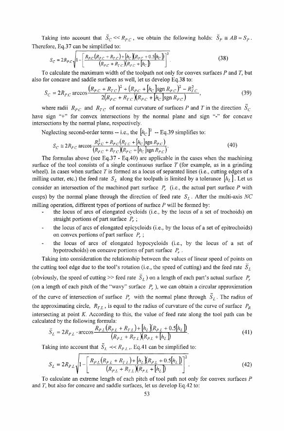
Taking into account that Se« Rp.e , we obtain the following holds: S p ;: AB = S p .
Therefore, Eq.37 can be simplified to:
(38)
To calculate the maximum width of the toolpath not only for convex surfaces P and T, but also for concave and saddle surfaces as well, let us develop Eq.38 to:
Se = 2Rp e arccos (Rp.e + Rr.e Y + (Rp.c + [he ]sgn Rpe Y -Ric , . 2(Rp.e + Rr.e XRpe + [he ]sgn Rp.e )
(39)
where radii Rp.e and Rr.e of normal curvature of surfaces P and T in the direction Se have sign "+" for convex intersections by the normal plane and sign "-" for concave intersections by the normal plane, respectively.
Neglecting second-order terms -- Le., the [he ]2 -- Eq.39 simplifies to:
R2c + R (R + [hclsgnR ) Sc ;: 2Rpc arccos P. P.C r.c P.C . (40) . (Rpc + Rr.c XRpc + [he lsgn Rpc )
The formulas above (see Eq.37 - Eq.40) are applicable in the cases when the machining surface of the tool consists of a single continuous surface T (for example, as in a grinding wheel). In cases when surface T is formed as a locus of separated lines (i.e., cutting edges of a milling cutter, etc.) the feed rate S L along the toolpath is limited by a tolerance [hL ]. Let us
consider an intersection of the machined part surface Pr (Le., the actual part surface P with
cusps) by the normal plane through the direction of feed rate S L . After the multi-axis NC
milling operation, different types of portions of surface P will be formed by: the locus of arcs of elongated cycloids (Le., by the locus of a set of trochoids) on straight portions of part surface Pr ;
the locus of arcs of elongated epicycloids (i.e., by the locus of a set of epitrochoids) on convex portions of part surface Pr ;
the locus of arcs of elongated hypocycloids (Le., by the locus of a set of hypotrochoids) on concave portions of part surface Pr .
Taking into consideration the relationship between the values of linear speed of points on
the cutting tool edge due to the tool's rotation (i.e., the speed of cutting) and the feed rate S L
(obviously, the speed of cutting » feed rate S d on a length of each part's actual surface Pr
(on a length of each pitch of the "wavy" surface Pr ), we can obtain a circular approximation
of the curve of intersection of surface Pr with the normal plane through S L . The radius of
the approximating circle, Rr.L' is equal to the radius of curvature of the curve of surface PR
intersecting at point K. According to this, the value of feed rate along the tool path can be calculated by the following formula:
2R RPL(RPL +RTL)+[hL](RPL +0.5[hLD L = PL' arccos ( X l D RPL + RTL RPL + hL
(41)
Taking into account that SL -<-< RP.L ,. Eq.41 can be simplified to:
S - 2R 1- [RPL (RPL + RTL )+ [hLKRPL + O.5[hLD]2 L - PL (RPL +RTLXRPL + [hLD
(42)
To calculate an extreme length of each pitch of tool path not only for convex surfaces P and T, but also for concave and saddle surfaces, let us develop Eq.42 to:
53

(43)
where radii Rp.L and RT.L of nonnal curvature of part surface P and the surface of
cutting in the direction Sc have sign "+" for convex intersections by the nonnal plane and
sign "-" for concave intersections by the nonnal plane, respectively.
Neglecting second-order tenns -- i.e., the [hL]2 -- Eq.43 simplifies to:
R2 + R (R + [h ]sgn R ) S L == 2Rp L arccos P.L P.L T.L L P.L. . (RpL + RT.[ XRn + [hL ]sgn Rn)
(44)
Eq.37 - Eq.40 and Eq.41 - Eq.44 allow calculation of maximum feed rates in the two
directions SL and Sc which guarantee approximately highest productivity of multi-axis NC
machining of sculptured part surfaces.
4. PRODUCTIVITY OF MULTI-AXIS NC MACHINING OF SCULPTURED PART SURFACES AS A FUNCTION OF DEGREE OF CONFORMITY OF THE SURFACES P AND T
Eq. 2 allows us to calculate the productivity of multi-axis NC machining of sculptured part surface P. Substituting into Eq.2 the maximum values of feed rates from Eqs.37 and 41, we can derive the following equation to calculate productivity of multi-axis NC machining:
E 4 RpL(RpL + RrJ+ [hLXRP.L +O.5[hLD = RpLRpc . arccos ( X [D .
. . RP.L + Rr.L RP.L + hL
Rpc(Rpc +Rrc)+[hcKRpc +O.5[hc D . arccos . (Rpc +RrcXRpc + [hcD
(45) Substituting into Eq.2 approximate maximum values for feed rates from Eqs.40 and 44,
we can derive the following approximate equation to calculate productivity of multi-axis NC machining of sculptured part surfaces P:
E == 4R R arccos R;c + Rp.c (Rrc + [hc ]sgn Rp.c) . PC PL (Rpc + Rr.c XRpc + [hc ]sgn Rpc ) (46)
. arccos R;L + RP.L (RT.L + [hL ]sgn RP.L) (RP.L + RTL XRP.L + [hL ]sgn RpL )'
It is important to emphasize that for a given relative local orientation of the surfaces P and T, the width of the toolpath depends upon the direction of relative motion of surfaces P and T. This direction is determined by the angle rp - the angle of orientation of the nonnal
plane in which the radii Rp.L and RT.C of nonnal curvatures of the surfaces P and T are
measured. According to Euler's fonnula:
R - Rl.pR2.P . (47) P.c - . 2 2 '
Rl.p sm rp + R2.P cos rp
R - RLTR2.T (48) T.C - RLT sin 2 (rp + .u)+ R2T cos2(rp + .u)'
where Rl.p , R2P - are the radii of the principal curvatures of the sculptured part surface, p.
54
Rl.r ' R2.r - are the radii of the principal curvatures of the machining surface of
the tool, T. According to Eq.47 and Eq.48, formula (37) can be rewritten as follows:
S - 2R () Rp.c [Rp dqJ) + Rr dqJ, .u)] + [hc ]{Rp dqJ) + O.s[hc ]} c - PC qJ arccos [RpAqJ) + RrdqJ, .u)]{RpdqJ)+[hc ]}
(49)
Such equations are also true for feed rate S L . Without derivation, let us write one of them
as the analog of Eq.49:
S - 2R () RPL [RPL (qJ) + RT L (qJ, .u)] + [hL ]{RPL (qJ) + 0.5[hL]} L - PL qJ arccos [RPL(qJ)+RTL(qJ, .u)]{RPL(qJ)+[hrl}
(50)
One of the possible ways to calculate values for the radii of normal curvature RP.L' Rpc , Rr.L , Rrc of surfaces P and Tin Eq.47 - Eq.50 is the following. Using well
known formulas for coordinate system transformation, we can rewrite the equations for the Dupin indicatrices of isogonally parametrised surfaces P and T given in a local isogonal coordinate system (with origin at the point of contact K of surfaces P and T and with two axes in a common tangent plane) into a local polar coordinate system as follows:
EG r = p p .
p GpLp cos2 qJ+MpJE;G;sin2qJ+EpN p sin 2 qJ , (51)
ErGr (52)
where rp , rr - the position vectors of points on Dupin's indicatrices of surfaces P and T,
respectively; Er , Fr , Gr - are the Gaussian coefficients of the first fundamental form cI>l.r of the
machining surface of a tool, T; L p, M p, N p - are the Gaussian coefficients of the second fundamental form cI> 2P of the
sculptured part surface, P; Lr , M T' NT - are the Gaussian coefficients of the second fundamental form cI> 2.r of the
machining surface of a tool, T. Whenever surfaces P and T have orthogonal parameterizations, Eqs. 51 and 52 simplify
to:
(53)
Lr cos2 (qJ + .u)+ M T sin 2(qJ + .u)+ N r sin 2 (qJ +.u)' (54)
The direction of feed rate Sc is determined by the angle qJ; the direction of feed rate
S L is determined by the angle ,;, and is usually perpendicular to the direction of feed rate
Sc - qJl = 90° ). The radii of normal curvature RP.L' Rp.c, Rr.L , Rr.c of surfaces P and T
in Eqs.51 - 52 can be calculated by the formulas:
R - . P.C - GpLp cos2,; + M p sin 2'; + EpN p sin2,;'
(55)
R = . rc GrLr cos2(,; + .u)+ M sin 2('; +.u)+ ErN r sin2(,; +.u)'
(56)
55

R = . n sin2q+EpNpcos2(
R = ETGT . T.L GTLT sin 2 (q + fl)+ M T ETGT sin 2(q + fl)+ ETN T cos2 (q + fl)'
If the parametrisations of surfaces P and Tare both orthogonal, Eqs.55 - 58 simplified and used in Eqs.53 - 54 in the form:
Rp.c = (Lp cos2 q +Mp sin2q + Np sin 2 qt;
Rrc = (Lp cos2 (q + fl)+ M p sin2(q + fl)+ N p sin 2 (q + fl))-\
Rn = (Lp sin 2 q +Mp sin2q +Np cos 2 q)-l;
Rn = sin 2 (q + fl)+ M p sin2(q + fl)+ Np cos 2 (q + fl))-l;
(57)
(58)
can be
(59)
(60)
(61)
(62)
The equations above hold for all cases of multi-axis Ne machining of smooth sculptured part surfaces P by cutting tools with "smooth" (non-toothed) machining surfaces T. Analysis ofEq.46 after substituting into it Eqs.55 - 58 (or Eqs.59 - 62) ifparametrisations of surfaces P and T are both orthogonal) shows that in Eq.l0, the function E = E(rp) is a nonlinear function
with respect to parameter rp. The same result can be obtained due to analysis of Eq.2 after substituting into it Eq.40 and Eq.44, taking into account Eqs.55 - 58 (or Eqs.59 - 61 if the parametrisations of surfaces P and T are both orthogonal). For that reason, productivity of multi-axis NC machining of sculptured part surfaces can be considered as a function of conformity of surfaces P and T. Because of this, the introduction of geometric analogs for productivity of machining is possible. For example, the optimal parameters of part surface machining can be determined not from the extremely bulky equation of productivity of part surface machining, but rather from a geometric analog - the indicatrix of conformity of surfaces P and T (Radzevich, 1991):
EpGp
(63)
where reon! - is a position vector ofa point of the indicatrix of conformity.
Eq.63 does not allow calculating the productivity of multi-axis Ne machining of sculptured part surfaces, but it is possible to determine the parameters for an extremely efficient machining process, because the direction of optimal motion of the cutting tool relative to the workpiece is orthogonal to the direction in which reo/if. is extremely small. To
find the direction of smallest radius reO/if of the indicatrix of conformity (Eq.63) -- i.e., to
define the value of angle rp -- is a trivial problem.
5. CONCLUSIONS
There are numerous ways to control the parameters of the process of multi-axis Ne machining of sculptured part surfaces with the goal of reaching extremely high efficiency of the manufacturing process. From our point of view, the most promising approach is to improve the process of generating the sculptured part surfaces. There exist good possibilities and a lot of unused reserve knowledge within the geometric and kinematic aspects of the process.
56

The approach developed above is based on a differential geometric method of multi-axis NC generation of sculptured part surfaces, and needs in criteria of optimization of machining process parameters. The best criterion for optimization is the minimization of the cost of part production. But such an optimization criterion has an extremely bulky analytical description, so is not convenient to apply. Productivity of multi-axis NC machining of sculptured part surfaces may be more simply described analytically, but it is also inconvenient to apply. Good results can be obtained due to introduction of geometric analogs of productivity of part surfaces machining -- the so-called conformity functions of surfaces P and T.
The approach developed above needs a powerful computer, modern numerically controlled machine tools, and highly developed CAM systems.
ACKNOWLEDGEMENTS
The authors acknowledge the International Technology Incubator of the Case Center for Computer-Aided Engineering and Manufacturing, Michigan State University, for partial support of this work.
REFERENCES I. Amirouche, F.M.L., Computer-Aided Design and Manufacturing, Prentice Hall, Englewood
Cliffs, N.J., 537p. 2. Chen, Y.D., Ni, J., Wu, S.M., Real-time CNC Tool Path Generation for Machining IGES
Surfaces. ASME Journal of Engineeringfor Industry, November 1993, Vol. 115, pp.480-486. 3. Chou,l-J., Yang, D.C.H., Command Generation for Three-Axis CNC Machining, ASME Journal
of Engineeringfor Industry, August 1991, Vol. 113, pp.305-310. 4. Chou,l-J., Yang, D.C.H., On the Generation of Coordinated Motion of Five-Axis CNC/CMM
Machines, ASME Journal of Engineeringfor Industry, February 1992, Vol. 114, pp.15-22. 5. doCarmo, M.P., Differential Geometry of Curves and Swjaces, Prentice Hall NY, 1976. 6. Dong, Z., Li, H., Vickers, G.W., Optimal Rough Machining of Sculptured Parts of a CNC
Milling Machine, ASME Journal of Engineeringfor Industry, November 1993, Vol. 115, pp.424-431.
7. Gauss, K.-F., Disquisitions Generales Circa Supeljicies Curvas, Gottingen, 1828. (English translation: General Investigation of Curved Suljaces, by lC.Moreheat & AM.Hiltebeitel, Princeton, 1902, reprinted with introduction by Courant, Raven Press, Hewlett, New York, 1965,119p.).
8. Oliver, lH., Efficient Intersection of Surface Normals With Milling Tool Swept Volume for Discrete Three -Axis NC Verification, ASME Journal of Mechanical Design, June 1992. Vol. 114, pp.283-287.
9. Oliver, lH., Wysocki, D.A., Goodman, E.D., Gouge Detection Algorithm for Sculptured Surfaces NC Generation, ASME Journal of Engineeringfor Industry, February 1993, Vol. 115, pp.139-144.
10. Philpott, M.L., Mitchell, S.E., Tobolski, J.F., Green, P.A, Simultaneous In-Process Inspection of Surface Form and Roughness of Machined Sculptured Surfaces, ASME Journal of Engineering for Industry, August 1995,Vol. 117, pp.430-438.
11. Radzevich, S.P., Multi-Axis NC machining of sculptured part surfaces, Vishcha Shkola Publishing House, Kyiv, 1991, 192p., (In Russian).
12. Reshetov, D.N., Portman, V.T., Precision of Machine Tools, Mashinostroyeniye Publishing House, Moscow, 1986, 336p., (In Russian).
13. Struik,DJ., Lectures on Classical Differential Geometry, Addison-Wesley Publishing Co., Inc., London, 1961, 232p.
14. Suresh, K., Yang, D.C.H., Constant Scallop-height Machining of Free-form Surfaces, ASME Journal of Engineeringfor Industry, May 1994, Vo1.116, pp.253-259.
15. Vichers, G.W., Quan, K.W., Ball-Mills Versus End-Mills for Curved Surfaces Milling, ASME Journal of Engineeringfor Industry, February 1989, Vol. 111, pp.22-26.
57

16. Wang, H., Chang, H., Wysk, R.A, Chandawarkar, A, On the Efficiency of NC Tool Path Planning for Face Milling Operations, ASME Journal of Engineering for Industry, November 1987,Vol.l09,370-376.
17. You, S.J., Ehmann, K.F., Scallop Removal in Die Milling by Tertiary Cutter Motion, ASME Journal of Engineeringfor Industry, August 1989, Vol. 111, pp.213-219.
18. You, S.J., Ehmann, K.F., Synthesis and Generation of Surfaces Milled by Ball End Mills Under Tertiary Motion, ASME Journal of Engineering for Industry, February 1991, Vol. 113, pp.l7-24.
58