efficiency improvement of a series-parallel hybrid
TRANSCRIPT
HAL Id: hal-02403978https://hal.archives-ouvertes.fr/hal-02403978
Submitted on 11 Dec 2019
HAL is a multi-disciplinary open accessarchive for the deposit and dissemination of sci-entific research documents, whether they are pub-lished or not. The documents may come fromteaching and research institutions in France orabroad, or from public or private research centers.
L’archive ouverte pluridisciplinaire HAL, estdestinée au dépôt et à la diffusion de documentsscientifiques de niveau recherche, publiés ou non,émanant des établissements d’enseignement et derecherche français ou étrangers, des laboratoirespublics ou privés.
Efficiency Improvement of a Series-Parallel HybridElectric Powertrain by Topology Modification
Bilal Kabalan, Emmanuel Vinot, Yuan Cheng, Rochdi Trigui, ClémentDumand, Taha El-Hajji
To cite this version:Bilal Kabalan, Emmanuel Vinot, Yuan Cheng, Rochdi Trigui, Clément Dumand, et al.. Ef-ficiency Improvement of a Series-Parallel Hybrid Electric Powertrain by Topology Modification.IEEE Transactions on Vehicular Technology, Institute of Electrical and Electronics Engineers, 2019,�10.1109/TVT.2019.2952190�. �hal-02403978�

This is the post print version of the final paper published in IEEE Transactions on Vehicular Technology
Doi: 10.1109/TVT.2019.2952190, ISSN: 1939-9359
1
Abstract— Among Series-Parallel Hybrid Electric Vehicle
(SPHEV) powertrains, the Power-Split architecture with a
planetary gear has an exemplary energetic efficiency in mixed
driving conditions. Nevertheless, a simple SPHEV architecture
can be realized without a planetary gear. It consists of 2 Electric
Machines (EM) mounted on the engine shaft and separated by a
clutch. With no power-split operation, this architecture allows the
vehicle to operate in pure electric, or series hybrid, or parallel
hybrid mode. It was proven to be less efficient than a reference
Power-Split SPHEV: the Toyota Hybrid System (THS). The aim
of this paper is to investigate the potential of efficiency
improvement of the simple SPHEV powertrain by topology
modification: the addition of gears for the components or a
gearbox with few number of ratios. Two new variants of SPHEVs
are proposed. The versions of SPHEVs and the reference THS are
optimized by a bi-level optimization technique using Genetic
Algorithm and Dynamic Programming. Compared to the simple
SPHEV, results show an efficiency worsening in one variant and
an efficiency improvement in another variant with a fuel
consumption comparable to the one of THS. A global sensitivity
study is then performed on the worsened variant. The sensitivities
of the added gears are determined and an elimination of some is
suggested. A new variant with fewer gears is therefore proposed
and optimized. The efficiency is improved but remains less than
the one of THS.
Index Terms— Dynamic programming, Genetic algorithms,
Hybrid Electric Vehicles, Optimization, Powertrain Design.
I. INTRODUCTION
HE automotive sector is ongoing important
transformations. For instance, the move in the course of
vehicle hybridization and electrification is widely seen in the
announced strategic plans of car manufacturers [1], [2], [3].
This move is driven by a need to meet the fleet average CO2
targets (EU objective of 37.5% reduction in 2030 compared to
Copyright (c) 2015 IEEE. Personal use of this material is permitted.
However, permission to use this material for any other purposes must be
obtained from the IEEE by sending a request to [email protected].
This paper was submitted for review on August 20, 2019. This work was
part of a PhD between IFSTTAR and Groupe PSA.
B. Kabalan (e-mail: [email protected]) is with IFSTTAR / AME /
ECO7, 25 Av. Francois Mitterrand, 69675 Bron, France and Groupe PSA,
Centre Technique Vélizy A, case courrier VV1415, Route de Gizy, 78943
Vélizy-Villacoublay Cedex, France.
E. Vinot (e-mail: [email protected]) and R. Trigui (e- mail:
[email protected]) are with IFSTTAR / AME / ECO7, 25 Av. Francois
Mitterrand, 69675 Bron, France.
Y. Cheng (e-mail: [email protected]) and C. Dumand (e-mail:
[email protected]) are with Groupe PSA, Centre Technique Vélizy
A, case courrier VV1415, Route de Gizy, 78943 Vélizy-Villacoublay Cedex,
France.
T. El Hajji (e-mail: [email protected]) is with Groupe PSA.
2021 [4] for passenger cars), the stringent pollutant emissions
standards, and the clients’ new demands.
Different challenges come with the proposed electrified
powertrains. Battery Electric Vehicles (BEVs) have a relatively
simple powertrain, but their main challenge is on the battery
side (autonomy, charging time, cost...). Hybrid Electric
Vehicles (HEVs) and Plug-in (PHEVs) are challenged by the
complexity, cost, and control of the powertrain and the
complexity of its design. In the following, (P)HEV will be used
to refer to HEV and PHEV.
A. (P)HEV design problem
(P)HEV powertrains combine a battery electric traction
system with a conventional engine-based traction system. The
two systems can be connected through different means,
resulting in various (P)HEV powertrain architectures. Series,
parallel and series-parallel (power-split and non-power-split)
are the main categories of existing hybrid architectures [5].
Once the architecture is chosen, different components
technologies can be selected, and different sizing can be made
(battery size, components power, gear ratios). The powertrain
operation and fuel consumption on a selected driving cycle will
depend on the architecture chosen, on the components chosen,
on their sizing, and lastly on the energy management during the
vehicle operation.
In view of this, the (P)HEV powertrain is an intricate system
whose design complexity is linked to the numerous variables
that need to be fixed. This can be seen as a multi-objective
optimization problem that is spread over multiple levels [6], [7].
The involved variables can be divided into 3 levels (Fig. 1): (1)
Architecture level, (2) Components technology and sizing level,
(3) Control level.
Fig. 1. (P)HEV powertrain design space
The choice of those variables is done taking into account
different criteria related to the vehicle requirements:
Efficiency Improvement of a Series-Parallel Hybrid
Electric Powertrain by Topology Modification
B. Kabalan, E. Vinot, Y. Cheng, R. Trigui, C. Dumand, and T. El Hajji
T

This is the post print version of the final paper published in IEEE Transactions on Vehicular Technology
Doi: 10.1109/TVT.2019.2952190, ISSN: 1939-9359
2
performance, fuel consumption, emissions, all-electric range
(AER), components lifetime, powertrain cost, powertrain
volume, compactness, and other criteria. Some of those criteria
are constraints to respect, while others are objectives to
optimize.
Various works are done in the literature in the context of this
(P)HEV optimization. They tackle the optimization on level (2)
and (3) with less efforts on including the level of architecture in
the optimization: few benchmark architectures are selected,
optimized on the two levels (2) and (3), and then compared. For
example, in [8] a topology optimization is presented and three
parallel hybrid topologies are compared while varying the
transmission technology and the component sizing.
However, the design space on the architecture level has not
been entirely screened yet. This is because listing and
modelling all the architectures manually is infeasible. In
addition, it is because of the model complexity and computation
time burden associated with the architectures evaluation and
optimization, in case of exhaustive search. Nevertheless, few
works started to propose architecture modifications [9], while
others started to perform some automatic generation of
architectures, in a way to discover a wider part of the
architecture level instead of sticking to the few benchmark
architectures [10], [11]. In [12] a systematic design
methodology is proposed. It generates and compares power-
split architectures with two planetary gears.
B. SPHEV architectures
According to [13], series-parallel architectures (SPHEV)
benefit from the advantages of series and parallel, but they have
relatively a more expensive design and complicated control.
The most common SPHEV powertrain is the power-split
SPHEV that uses a Planetary Gear (PG) as a power-split unit.
The Toyota Prius was the first adopter of this architecture in the
Toyota Hybrid System (THS) [14], (Fig. 2). Chevrolet Volt and
Opel Ampera also adopted the power-split architecture [15].
In power-split SPHEV, the PG decouples the Internal
Combustion Engine (ICE) speed from the wheels speed,
allowing a speed degree of freedom (DoF), in addition to the
torque DoF that is present in any parallel architecture. This
helps in moving the operating points of the ICE on its high
efficiency area. The cost of this double freedom is that the
power going to the wheels is always split between a parallel
path and a series path, the latter having a lower efficiency due
to the added energy conversion stages. Still, power-split
SPHEV remain ones of the most efficient mass produced HEV
[16], [8] and the THS is widely used as a reference powertrain.
Nevertheless, other SPHEVs can be realized without a
planetary gear system [18]. A simple SPHEV powertrain with
no PG was studied in [19] (Fig. 3). It consists of 2 Electric
Machines (EM) mounted on the ICE shaft and separated by a
clutch. It is relatively a simple architecture that allows
vehicle operation in pure electric, series hybrid or parallel
hybrid mode. The switching between the modes is done through
clutch engaging or disengaging. In contrast to power-split
SPHEV, the powertrain does not operate in power-split between
series and parallel modes. Its advantage is the possibility to
operate in pure parallel mode, avoiding the losses of the series
path. Its disadvantage is that the speed DoF is only available in
the series mode. It is then more difficult to operate the system
in its best efficiency areas compared to power-split SPHEV. In
fact, the vehicle speed and torque demands might constraint the
powertrain to operate sometimes in series mode even when it
has relatively low efficiency. This simple SPHEV architecture
has thus been proven to be less efficient than the power-split
SPHEV [16].
C. Contribution and outline
This paper is concerned with discovering a wider part of the
architecture level. This is done by proposing some topology
modifications, optimizing the topologies and comparing
between them. In the scope of this paper, the comparison is
done based on the fuel consumption and the battery size. Instead
of considering parallel hybrid topologies with conventional
transmissions as in [8] or power-split architectures as in [12],
series-parallel topologies with simple transmission are
considered here because this paper is part of a global work that
is trying to search for new simple and efficient hybrid
architectures.
The objective of this paper is to investigate the potential of
improvement of the simple SPHEV powertrain by topology
modification, in the aim of discovering new simple and efficient
hybrid architectures. The paper starts by presenting the simplest
version of SPHEV and two proposed variants with added gears
or gearbox. The three versions of SPHEVs and the reference
THS are then optimized using a sizing and control bi-level
optimization methodology. Section II of this paper explains the
methodology used to perform this optimization. Section III
presents the results of this comparison. Then in section IV, a
sensitivity analysis is conducted on the proposed architecture
which has added gears. Based on this analysis, the sensitivities
of added gears are determined and an elimination of some is
suggested. A new architecture is therefore proposed. It will be
optimized and compared to the other architectures in section V,
using the same methodology.
II. METHODOLOGY
In this section, the chosen architectures are first introduced.
The system modelling is then described. Finally, the
methodology used to optimize the sizing and control of the
powertrains is presented.
A. Choice of architectures
The simplest SPHEV architecture is presented in Fig. 3 and
will be referred to as SPHEV 1 in the rest of the paper. It was
studied in [19] and [20]. The ICE and the EMs are on the same
shaft, separated by clutches. Table I lists the operating modes
of the powertrain in function of the clutches state.

This is the post print version of the final paper published in IEEE Transactions on Vehicular Technology
Doi: 10.1109/TVT.2019.2952190, ISSN: 1939-9359
3
Fig. 2. THS
Fig. 3. SPHEV 1
TABLE I
CLUTCHES STATE AND CORRESPONDING OPERATING MODE FOR SPHEV 1
C2 C1
Operating
mode
Involved
Components
DoF
Disengaged Disengaged Electric
mode 1
EM1 0
Disengaged Engaged Electric
mode 2
EM1,
EM2
1 power sharing
variable
Engaged Engaged Parallel
hybrid
mode
EM1,
EM2,
ICE
2 power sharing
variables
Engaged Disengaged Series
hybrid
mode
EM1,
EM2,
ICE
1-Pbat
2-ICE speed
To improve the powertrain efficiency, some topology
modifications can be considered: adding a gear between the
final shaft and each component (ICE and 2EM), or adding a
gearbox to the powertrain, with different possible number of
gears and different possible locations. As a first step, the
following 2 new variants of SPHEV are proposed:
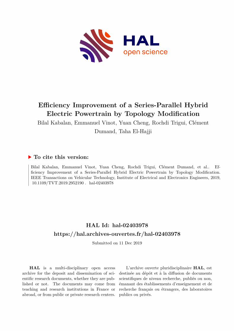
- SPHEV 2: a SPHEV with one added gear between the final
shaft and each component (Fig. 4).
- SPHEV 3: a SPHEV with a gear on each EM and a 2-
speed gearbox between the 2 EMs (Fig. 5). SPHEV 3 has
the same functionality of an architecture proposed by
Denso Corporation in [21].
SPHEV 2 has the same operating modes and corresponding
DoF as SPHEV 1 (Table I). SPHEV 3 has same modes;
however a gear selection DoF is added for the electric mode 2
and the parallel hybrid mode. The number of gears in the
gearbox of SPHEV 3 is chosen to be two and is not optimized
in this work.
Fig. 4. SPHEV 2
Fig. 5. SPHEV 3
B. System modelling
In order to assess the different powertrains, the vehicle in its
environment needs to be modelled. Energetic models are thus
developed on MATLAB using the VEHLIB [22] library of
vehicle components and the longitudinal dynamics law. The
backward approach is used to calculate the fuel consumption,
while the forward approach is used to calculate the vehicle
performance.
Concerning the component models, experimental Brake-
Specific Fuel Consumption (BSFC) maps are used for the
engine. The electric machines and their converters are modelled
using losses maps. The losses of the EMs are generated from
reluctance network models (at 500V) that were validated by a
finite element model [23] and experimental data [24]. The
losses of the inverters are calculated using an analytical model
based on inverter parameters (switching losses, switching
frequency, recovery charge,…). The global losses (EMs +
inverters) will be considered to be independent from the battery

This is the post print version of the final paper published in IEEE Transactions on Vehicular Technology
Doi: 10.1109/TVT.2019.2952190, ISSN: 1939-9359
4
voltage. A classical equivalent electric circuit model is used for
the battery which is considered to be modules in series, for
simplicity reason. The choice of series or parallel configuration
for the battery modules will not affect the converters and EMs
losses. Gear losses are modelled by assigning a constant
efficiency to each gear. The sizing of the components is not
fixed and will be optimized.
The sizing variables involved are:
the maximum power of the ICE, of EM1 and of EM2
the number of battery modules in series
the ratios of the gears, if existing
the ratios of the gearbox, if existing
When the sizing variables are chosen by the sizing optimizer,
the component characteristics are updated. A scaling technique
is done for the ICE and EMs. The scaling factor is the ratio
between the sized power and a reference power. The maximum
torque curves, the fuel consumption, the power losses maps,
and the weight are multiplied by this factor. The inertia is
multiplied by this factor to the power 5/3. For the EMs, the
thermal boundaries and the geometry was not considered here
but was considered in [25]. Concerning the battery, the sizing
is performed by changing the number of cells in series. The
voltage, maximum power, stored energy and weight are
recomputed. The influence of the battery voltage on the EM and
converters losses is neglected. For the gears, their ratios are
replaced by their sized values, without changing their
efficiency.
The vehicle models have also some control variables that
needs to be decided during the vehicle operation. They will be
presented in the following (Table II).
C. Optimization process
To guarantee a fair comparison between the architectures, an
optimization process is performed beforehand for each of them
to ensure that they are compared based on their optimal
potential.
As explained before, the vehicle model has sizing variables
that needs to be decided when the powertrain is being designed,
and control variables that needs to be decided instantaneously
when the powertrain is being operated. A bi-level optimization
process is adopted [20], [26], [16]: an upper level sizing
optimization for the designing phase and a lower level control
optimization for the operation (Fig. 6). This process yields to a
Pareto front presenting the tradeoff between the objective
functions.
1) Upper level sizing optimization
The optimization variables on this level are the sizing
variables listed in the previous subsection. The architectures
can have up to 9 sizing variables; therefore the design space of
this optimization can have up to 9 dimensions. The genetic
algorithm (GA) NSGA-II [27] is used as the optimization
algorithm. GA performs the exploration of this design space
and generates at the end of the optimization the optimal tradeoff
(Pareto fronts) between the objective functions.
The algorithm chooses at each step the sizing candidates to
be assessed (set of values for the sizing variables). GA
initializes a random population of sizing candidates. After an
evaluation of the objective functions of this population, GA
performs an evolution process (Selection, Crossover, and
Mutation) to produce better generations. For each generated
individual, the performance constraint is checked. If it is
respected, the objectives are assessed. In this paper, two
objectives are considered: the charge sustaining fuel
consumption calculated using lower level optimization (DP),
and the number of battery modules in series. The latter is an
indicator of the battery stored energy and is one of the sizing
variables, it does not need to be calculated again. This objective
function was selected because it reflects the amount of
electrification. It has an influence on the energy management
and thus the fuel consumption. A high battery size leads to
reduction in fuel consumption because the powertrain can
recuperate more energy when needed and has more energy
freedom when choosing between electric and hybrid modes. In
addition the importance of the architecture on the fuel
consumption might decrease when the battery size is big. The
process is repeated until a maximum number of iterations is
reached. More explanations can be found in [27]. In previous
works, the Pareto fronts were compared from 200 to 1000
Genetic Algorithm
Initialization Choice of sizing candidate
{𝑁𝑏𝑎𝑡, 𝑃𝐼𝐶𝐸, 𝑃𝐸𝑀𝑠, Gear ratios}
Objectives calculation:
1- Battery size 2- Optimal fuel consumption
Upper level sizing optimization
Lower level control optimization
Solve DP problem
Max number of
iterations
no
yes
no yes
Pareto Front
Selection Mutation Crossover
Performance check
Fig. 6. Optimization process

This is the post print version of the final paper published in IEEE Transactions on Vehicular Technology
Doi: 10.1109/TVT.2019.2952190, ISSN: 1939-9359
5
generations for different optimizations. No change in the Pareto
was seen after 500 generations.
In the performance check, a test is performed to ensure that
the sizing candidate respects the following constraints:
the acceleration time from 0 to 100 km/h:
𝑡0−>100 < 10.1 s
Acceleration time from 80 to 120 km/h:
𝑡80−>120 < 7.5 s
the maximum speed of the vehicle on a flat road:
𝑉𝑚𝑎𝑥 > 179𝑘𝑚/ℎ
This performance test is done in hybrid operation. The
powertrain choses the mode that maximizes the torque on the
wheels (series or parallel). For the parallel mode clutch slipping
is allowed when the engine speed is below a threshold value
which is higher than the idle speed. If a GB is involved, gear
upshifting is performed when one of the upstream components
reaches its shifting speed. The latter is the speed corresponding
to the maximum power of the ICE or EMs. At the vehicle
maximum speed in the performance test, the battery power is
not obliged to be null. However any candidate relying on the
battery power at high speeds will not be able to finish the
driving cycle used for the fuel consumption calculation because
of its long highway part, and will be normally dismissed at later
stage. Such constraint can be added in future work.
To calculate the fuel consumption, the vehicle is run on a
driving cycle. Here, a control optimization problem arises.
2) Lower level control optimization
The fuel consumption at the end of the cycle is strongly
dependent on the instantaneous choice of control variables
during the entire vehicle operation. For the 3 proposed
SPHEVs, the first control variable is the choice of operating
mode. In fact, a given speed and power demand of the vehicle
can be accomplished by the powertrain through 4 possible
operating modes (electric mode 1, electric mode 2, series hybrid
and parallel hybrid). When the gearbox is involved, a control
variable of gear selection is added. Specific control variables
also exist for each mode, except for electric mode 1. They are
listed in Table II.
TABLE II
STATE AND CONTROL VARIABLES PER ARCHITECTURE
State
variable
Control variables
SPHEV 1
and
SPHEV 2
SOC
Mode
choice
* 1 power sharing variable
between EM1 and EM2 in
electric mode 2
* 2 power sharing variables
between ICE, EM1 and EM2
in parallel hybrid
* Pbat and ICE speed in series
hybrid
SPHEV 3 SOC Mode
choice
Gear
choice
+ Same as above
THS SOC Pbat and ICE speed
For the electric mode 2 and the parallel hybrid mode, the
control variables are the power sharing between the involved
components. In the series mode, the control variables are the
battery power and the speed of ICE. For a given battery power
and a given power in propelling EM, the engine speed that
optimizes the ICE-EM2 system is predetermined before the
vehicle simulation. For the THS, the control variables are the
battery power and the speed of ICE. At each time step the
battery power is discretized; and for each battery power, the
engine speed is discretized and the value that maximizes the
powertrain efficiency is chosen. A time step of 1 second is used,
the SOC is discretized with around 1000 points between 20%
and 80%, and the ICE speed discretization step is 5 rad/s. More
details can be found in [28].
This control problem can be solved by different methods, or
Energy Management Strategies (EMS). They differ in their
optimality, computation time and ability to be implemented or
not in real time vehicle operation. In this work, the chosen EMS
is the Dynamic Programming (DP) which guarantees the global
optimal fuel consumption of each candidate on the entire cycle
[29], [30], [31]. The choice of DP implies that the architectures
are compared based on their optimal potential of fuel saving and
preserves consequently the fairness of comparison.
The global optimal fuel consumption calculated by DP is sent
back to the upper level where the genetic algorithm continues
the optimization process until a maximum number of
generations is reached. A Pareto front of the fuel consumption
versus the number of battery modules can be plotted for each
architecture. This is presented in the following section.
III. COMPARISON OF THE ARCHITECTURES
In this section, the 3 proposed SPHEV architectures and the
THS are compared. Before that, all architectures are optimized
using the previously presented optimization process.
For the optimization, the vehicle characteristics and
components used correspond to a middle class HEV and can be
found in Table III. The reference maps of EM1, EM2 and ICE
before sizing are shown in Fig. 7. The sized maps will be
generated by multiplying the torque and losses by the scaling
factor. TABLE III
COMPONENT SPECIFICATIONS
Component Specification
Engine Gasoline, Atkinson
EM1 Permanent Magnet Synchronous Motor
EM2 Permanent Magnet Synchronous Motor
Battery Nickel-metal hydride, (each module: 6.5 Ah
capacity, 1kW maximum power)
Gearbox 2-speed gearbox 98% efficiency
Components Gear parallel axis helical gears with a 98% efficiency
Final Drive 97% efficiency
Planetary Gear 97% efficiency
Vehicle middle class HEV

This is the post print version of the final paper published in IEEE Transactions on Vehicular Technology
Doi: 10.1109/TVT.2019.2952190, ISSN: 1939-9359
6
Fig. 7. EM1, EM2 and ICE maps before sizing
The fuel consumption objective function (FCons) is
evaluated in mixed driving condition. FCons is computed as a
weighted average of the fuel consumption in charge sustaining
mode in urban, rural road and highway conditions. The
ARTEMIS European driving cycles [32] are used to simulate
these three conditions and the control is optimized on each of
them.
𝐹𝐶𝑜𝑛𝑠 = 𝛼. 𝐹𝐶𝑜𝑛𝑠𝑢𝑟𝑏𝑎𝑛 + 𝛽. 𝐹𝐶𝑜𝑛𝑠𝑟𝑢𝑟𝑎𝑙 + 𝛾. 𝐹𝐶𝑜𝑛𝑠ℎ𝑖𝑔ℎ𝑤𝑎𝑦
(1)
Where the 𝛼, 𝛽 and 𝛾 are coefficients calculated from the
mean traveled distance by the French population in urban, rural
road and highway conditions. These values are respectively 0.4,
0.3 and 0.3 [33].
The Pareto fronts obtained at the end of 1000 iterations with
a population size of 100 are presented in Fig. 8.
The Pareto fronts shows that THS has globally a better fuel
consumption than SPHEV 1. This confirms the results found in
[6] and can be explained by the lack of speed degree of freedom
(DoF) in SPHEV 1 and the increased usage of the series mode.
Fig. 8. The optimization Pareto fronts
SPHEV 2 happens to be less efficient than SPHEV 1. The
reason behind the gears addition in SPHEV 2 was to try to move
the operating points of the system to better efficiency areas, and
to allow the parallel mode to be used more often. The effect of
this probable improvement seems to be less than the effect of
the deterioration in the power paths efficiencies
(due to gear losses), which results in a higher fuel consumption
for the SPHEV 2 powertrain. This result is highly dependent on
the gears efficiency which was chosen to be here 98% for each
added gear.
SPHEV 3 has comparable fuel consumption to THS (see
section V). Thanks to the addition of the 2-speed gearbox, the
improvements (caused by a more usage of the parallel mode
(Table IV) are now more important than the deterioration in the
power paths efficiencies. More details about this point can be
found in [20].
The results of the optimization of all the architectures will be
presented and elaborated in section V.
IV. SENSITIVITY ANALYSIS
In order to understand the influence of the gears addition on
the fuel consumption, a sensitivity study is conducted in this
section on SPHEV 2 sizing variables. The final target is to
identify the improvements that can be done on this architecture
and to finally propose a better version of it named SPHEV 2’.
In the context of a system model optimization, sensitivity
analysis refers to understanding the influence of the system
Scalin
g
Scalin
g
Scalin
g
This is the post print version of the final paper published in IEEE Transactions on Vehicular Technology
Doi: 10.1109/TVT.2019.2952190, ISSN: 1939-9359
7
optimization parameters on the optimization objective function.
Two approaches exist, local and global. While the local
sensitivity explores only a small fraction of the design space,
the global sensitivity uses a set of samples representative of the
entire design space [34]. The set of samples is chosen by
techniques like the Monte Carlo and Design of Experiments
(DOE) [35].
The global approach is selected in this work. The calculation
is done using the linear regression. Monte Carlo method is used
for the choice of samples. It generated 6561 sets of sizing to
be evaluated. The performance constraints are checked for all
those combinations, but the fuel consumption is calculated only
for the feasible combinations (842 out of 6561). Linear
Regression’s coefficients are finally calculated. They are shown
in Fig. 9. A negative sensitivity is found when the variable and
the fuel consumption have different sign of variation.
The arrows in Fig. 9 emphasize the difference in the sign of
the gears sensitivity. It can be seen that the sensitivities of the
Final Drive Ratio, the Gear for EM1 and the Gear for EM2 have
all the same sign. However, the sensitivity of the Gear for ICE
has a different sign.
Fig. 9. Global sensitivity results for SPHEV 2 architecture
This means that increasing the Final Drive Ratio, or the Gear
for EM1 or the Gear for EM2 will decrease the fuel
consumption. From here, it can be suggested to combine those
3 variables in 1 variable that touches all the components
affected by the 3 variables. This variable can be the Final Drive
Ratio that actually affects the speed and torque of all the
components. However, the Gear for ICE should be kept because
its sensitivity is in contradiction with the Final Drive Ratio.
Based on this, a new architecture is therefore proposed in the
following section.
V. NEW PROPOSED ARCHITECTURE
Based on the understanding of the global sensitivities of the
SPHEV 2 gears, a new simplified architecture SPHEV 2’ is
proposed (Fig. 10). SPHEV 2’ is achieved by removing 2 gears
from SPHEV 2. This should solve a main problem in SPHEV
2: the losses in the gears.
Fig. 10. The new proposed architecture SPHEV 2'
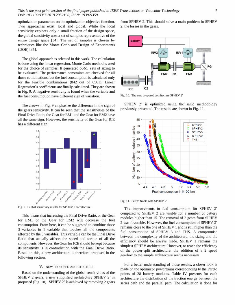
SPHEV 2’ is optimized using the same methodology
previously presented. The results are shown in Fig. 11.
Fig. 11. Pareto fronts with SPHEV 2'
The improvements in fuel consumption for SPHEV 2’
compared to SPHEV 2 are visible for a number of battery
modules higher than 15. The removal of 2 gears from SPHEV
2 was favorable. However, the fuel consumption of SPHEV 2’
remains close to the one of SPHEV 1 and is still higher than the
fuel consumption of SPHEV 3 and THS. A compromise
between the complexity of the architecture, the sizing and the
efficiency should be always made. SPHEV 1 remains the
simplest SPHEV architecture. However, to reach the efficiency
of the power-split architecture, the addition of a 2 speed
gearbox to the simple architecture seems necessary.
For a better understanding of those results, a closer look is
made on the optimized powertrains corresponding to the Pareto
points of 28 battery modules. Table IV presents for each
architecture the distribution of the traction energy between the
series path and the parallel path. The calculation is done for

This is the post print version of the final paper published in IEEE Transactions on Vehicular Technology
Doi: 10.1109/TVT.2019.2952190, ISSN: 1939-9359
8
mixed driving conditions. A low usage of the series path is seen
for SPHEV 3, compared to the other architectures. The 2-speed
gearbox of SPHEV 3 allows the powertrain to use the parallel
path more, while keeping the operating points of the
components in relatively good efficiency zones. This is why it
is found to be the most efficient.
TABLE IV
DISTRIBUTION OF THE TRACTION ENERGY*
BETWEEN SERIES AND PARALLEL PATHS FOR THE PARETO POINTS OF 28
BATTERY MODULES
*Traction energy in Wh during hybrid modes for mixed driving conditions,
calculated as: 𝛼 *urban + 𝛽 *rural + 𝛾 *highway, 𝛼=0.4, 𝛽 = 0.3, 𝛾 = 0.3
TABLE V
OPTIMAL SIZING FOR THE PARETO POINTS OF 28 BATTERY MODULES
TABLE VI
FUEL CONSUMPTION (L/100KM)
The powertrains optimal sizing is shown in Table V and their
fuel consumption in Table VI. An oversizing of all the
components is detected for SPHEV 1 and is linked to its high
usage of the series mode (Table IV) where all the power going
to the wheels is obliged to take one path instead of two (the case
in parallel mode).
This explains also its high fuel consumption. With the
addition of 3 gears, SPHEV 2 solves this oversizing problem
and reduces the series mode but results in higher fuel
consumption than SPHEV 1. If only 1 of those 3 gears is added
to SPHEV1 (case of SPHEV 2’), a downsizing of EM2 is
achieved and the fuel consumption is slightly improved.
A difference is noted in the optimal gear ratios of SPHEV 2
and SPHEV 2’. The total ratio for the ICE is highly impacted
(1.4*2.2 vs. 1.39*4.01). This should be explained by the ratio
of EM1 which remains more or less constant (1.94*2.2 vs.
4.01).
More reduction in sizing can be achieved by SPHEV 3 which
also has the least fuel consumption. It is found in [20] that this
is due to the urban driving, where 59% of the traction energy in
hybrid mode was transferred to the wheels using the series path
in THS, compared to only 9.5% in SPHEV 3. More details can
be found in [20]. It should be re-mentioned that the sizing here
was optimized for mixed driving conditions and that the 2-
speed gearbox efficiency is considered to be 98%.
VI. CONCLUSION
The design of (P)HEV powertrains is a complex task that
involve an optimization on 3 levels: Architecture, Components
technology & Sizing, and Control. This paper is part of a global
work that is trying to search the Architecture design space in
the aim of discovering new efficient hybrid architectures with
simple transmissions. The searching process is done in a non-
automatic way in this paper: the work starts from the simplest
series parallel architecture that can be realized. Then, knowing
this architecture’s weak points, 2 other variants are proposed
and studied. All architectures are optimized using a sizing and
control bi-level optimization methodology. A genetic algorithm
is used for the sizing, while the dynamic programming is used
for the control and guarantees the calculation of the global
optimal fuel consumption of each sizing candidate. The variant
with a gearbox showed good improvements and a potential of
fuel saving close to the THS architecture. The variant with 3
added gears showed however a decrease in efficiency. A global
sensitivity is therefore performed on this latter architecture and
an elimination of 2 gears is suggested. A new architecture is
proposed and assessed. The removal of the gears was beneficial,
but the architecture remains less efficient than the variant with
a gearbox. In future work, the Architecture exploration and
assessment will be automatized. The authors are working on
developing a tool that automatically generates the architectures
and automatically filter and assess them. In this tool the
synchronizers and gears can be placed anywhere between the
components, allowing the emergence of non-conventional
transmissions. Future works will also include additional aspects
of the powertrain in this assessment (compactness, weight, cost,
life cycle considerations,...).
REFERENCES
[1] Groupe PSA, “Intelligent technologies for plug-in vehicles,”
Innovation Day 2016, pp. 1–10, 2016.
[2] Renault-Nissan-Mitsubishi, “Alliance 2022: New plan targets
annual synergies of €10 billion and forecasts unit sales of 14 million
& combined revenues of $240 billion,” pp. 1–4, 2017.
[3] Volkswagen, “The Volkswagen Group launches the most
comprehensive electrification initiative in the automotive industry
with ‘Roadmap E,’” Volkswagen Gr. Media Serv., no. 308, pp. 1–4,
2017.
[4] European Comission, “Europe accelerates the transition to clean
mobility: Co-legislators agree on strong rules for the modernisation
Path THS SPHEV1 SPHEV2 SPHEV3 SPHEV2’
Series 547.3 1638.0 502.1 120.7 1836.3
Parallel 1926.6 875.7 1980.2 2359.6 664.5
THS SPHEV
1
SPHEV
2
SPHEV
3
SPHEV
2’
Power EM1
(kW)
58 84.1 68 59.3 85
Power EM2
(kW)
44.6 73.5 55.6 54.3 54.7
Power ICE
(kW)
47.9 59.9 48.3 52.1 56
PG 1.5 - - - -
FG 4.11 4.15 2.2 2.27 4.01
G1 - - 1.94 1.6 -
G2 - - 1.28 0.51 -
G3 - - 1.4 - 1.39
GB 1st - - - 2.3 -
GB 2nd - - - 1.06 -
Urban Rural Highway Mixed
SPHEV 1 4.45 4.02 5.85 4.74
SPHEV 2 4.47 3.97 6.15 4.82
SPHEV 3 4.15 3.82 5.63 4.50
SPHEV 2’ 4.31 4.06 5.93 4.72
THS 4.47 3.70 5.54 4.56

This is the post print version of the final paper published in IEEE Transactions on Vehicular Technology
Doi: 10.1109/TVT.2019.2952190, ISSN: 1939-9359
9
of the mobility sector,” 2018. [Online]. Available:
https://ec.europa.eu/clima/news/europe-accelerates-transition-clean-
mobility-co-legislators-agree-strong-rules-modernisation_en.
[Accessed: 15-Jan-2019].
[5] C. C. Chan, A. Bouscayrol, and K. Chen, “Electric, hybrid, and fuel-
cell vehicles: Architectures and modeling,” IEEE Trans. Veh.
Technol., vol. 59, no. 2, pp. 589–598, 2010.
[6] E. Silvas, T. Hofman, N. Murgovski, P. Etman, and M. Steinbuch,
“Review of Optimization Strategies for System-Level Design in
Hybrid Electric Vehicles,” IEEE Trans. Veh. Technol., vol. 66, no.
1, pp. 57–70, 2017.
[7] W. van Harselaar, T. Hofman, and M. Brouwer, “Automated
Dynamic Modeling of Arbitrary Hybrid and Electric Drivetrain
Topologies,” IEEE Trans. Veh. Technol., vol. 67, no. 8, pp. 6921–
6934, 2018.
[8] T. Hofman, S. Ebbesen, and L. Guzzella, “Topology Optimization
for Hybrid Electric Vehicles With Automated Transmissions,” IEEE
Trans. Veh. Technol., vol. 61, no. 6, pp. 2442–2451, 2012.
[9] X. Zhang, C.-T. Li, D. Kum, and H. Peng, “Prius(+) and Volt(-):
Configuration Analysis of Power-Split Hybrid Vehicles With a
Single Planetary Gear,” IEEE Trans. Veh. Technol., vol. 61, no. 8,
pp. 3544–3552, 2012.
[10] E. Silvas, T. Hofman, A. Serebrenik, and M. Steinbuch, “Functional
and Cost-Based Automatic Generator for Hybrid Vehicles
Topologies,” IEEE/ASME Trans. Mechatronics, no. iv, pp. 1–11,
2015.
[11] J. Wijkniet and T. Hofman, “Modified Computational Design
Synthesis Using Simulation-Based Evaluation and Constraint
Consistency for Vehicle Powertrain Systems,” IEEE Trans. Veh.
Technol., vol. 67, no. 9, pp. 8065–8076, 2018.
[12] X. Zhang, S. E. Li, H. Peng, and J. Sun, “Design of Multimode
Power-Split Hybrid Vehicles - A Case Study on the Voltec
Powertrain System,” IEEE Trans. Veh. Technol., vol. 65, no. 6, pp.
4790–4801, 2016.
[13] C. C. Chan, “The state of the art of electric, hybrid, and fuel cell
vehicles,” Proc. IEEE, vol. 95, no. 4, pp. 704–718, 2007.
[14] K. Muta, M. Yamazaki, and J. Tokieda, “Development of new-
generation hybrid system THS II-Drastic improvement of power
performance and fuel economy,” 2004.
[15] U. D. Grebe and L. T. Nitz, “Voltec – The Propulsion System for
Chevrolet Volt and Opel Ampera,” MTZ worldwide, vol. 72, no. 5,
Springer Automotive Media, pp. 4–11, 15-May-2011.
[16] E. Vinot, “Comparison of different power-split hybrid architectures
using a global optimization design method.,” Int. J. Electr. Hybrid
Veh., vol. 8, no. 3, pp. 225–241, 2016.
[17] E. Vinot, V. Reinbold, and R. Trigui, “Global Optimized Design of
an Electric Variable Transmission for HEVs,” IEEE Trans. Veh.
Technol., vol. 65, no. 8, pp. 6794–6798, 2016.
[18] N. Higuchi and H. Shimada, “Efficiency enhancement of a new
two-motor hybrid system,” World Electr. Veh. J., vol. 6, no. 2, pp.
325–335, 2013.
[19] R. Trigui, E. Vinot, and B. Jeanneret, “Backward Modeling and
Energy Management Optimization of a Two Clutches Series-
Parallel HEV for Efficiency Assessment,” in Power plant and
power system control symposium IFAC PPPSC), 2012, 2012.
[20] B. Kabalan, E. Vinot, Y. Cheng, R. Trigui, and C. Dumand,
“Improvement of a Series-Parallel Hybrid Electric Vehicle
Architecture,” in 2017 IEEE Vehicle Power and Propulsion
Conference (VPPC), 2017, pp. 1–6.
[21] S. Washino, T. Saito, and Y. Jia, “New 3 Mode Hybrid System
Concept,” 24th Aachen Colloq. Automob. Engine Technol. 2015,
2015.
[22] E. Vinot, J. Scordia, R. Trigui, B. Jeanneret, and F. Badin, “Model
simulation, validation and case study of the 2004 THS of Toyota
Prius,” Int. J. Veh. Syst. Model. Test., vol. 3, no. 3, pp. 139–167,
2008.
[23] V. Reinbold, E. Vinot, L. Garbuio, and L. Gerbaud, “Optimal sizing
of an electrical machine using a magnetic circuit model: application
to a hybrid electrical vehicle,” IET Electr. Syst. Transp., vol. 6, no.
1, pp. 27–33, 2016.
[24] ORNL, “Evaluation of 2004 Toyota Prius hybrid electric drive
system,” 2006.
[25] M. Le Guyadec, L. Gerbaud, E. Vinot, and B. Delinchant,
“Sensitivity analysis using Sobol indices for the thermal modelling
of an electrical machine for sizing by optimization,” COMPEL - Int.
J. Comput. Math. Electr. Electron. Eng., vol. 38, 2019.
[26] B. Kabalan, Y. Cheng, E. Vinot, C. Dumand, R. Trigui, and W. Bou
Nader, “Optimal Design and Sizing of Through-The-Road Hybrid
Vehicle Powertrain,” in SIA Powertrain 2018, 2018, pp. 1–7.
[27] K. Deb, A. Pratap, S. Agarwal, and T. Meyarivan, “A Fast and
Elitist Multiobjective Genetic Algorithm : NSGA-II,” IEEE Trans.
Evol. Comput., vol. 6, no. 2, pp. 182–197, 2002.
[28] E. Vinot, R. Trigui, Y. Cheng, C. Espanet, A. Bouscayrol, and V.
Reinbold, “Improvement of an EVT-based HEV using dynamic
programming,” IEEE Trans. Veh. Technol., vol. 63, no. 1, pp. 40–
50, 2014.
[29] R. E. Bellman, Dynamic Programming. Princeton University Press,
1957.
[30] E. Vinot, “Time reduction of the dynamic programming
computation in the case of hybrid vehicle,” in Optimization &
Inverse Problems in Electromagnetism (OIPE), 2014, 2014.
[31] O. Sundstrom, D. Ambuhl, and L. Guzzella, “On implementation of
dynamic programming for optimal control problems with final state
constraints,” Oil Gas Sci. Technol. l’Institut Fran{ç}ais du
P{é}trole, vol. 65, no. 1, pp. 91–102, 2010.
[32] M. André, “The ARTEMIS European driving cycles for measuring
car pollutant emissions,” Sci. Total Environ., vol. 334–335, pp. 73–
84, Dec. 2004.
[33] Eurostat, “Eurostat statistic on population displacement,
http://epp.eurostat.ec.europa.eu/portal/page/portal/transport/data/dat
abase
http://appsso.eurostat.ec.europa.eu/nui/show.do?dataset=road_tf_roa
d&lang=fr.” .
[34] A. Saltelli et al., Global Sensitivity Analysis. 2008.
[35] J. Goupy and L. Creighton, Introduction aux plans d’expériences.
2006.
B. Kabalan received his Bachelor of
Engineering B.E. in Mechanical
Engineering from the Lebanese American
University, Byblos, Lebanon in 2015. He
received a Master of Science M.S. degree
in Powertrain Engineering from IFP
School, Rueil-Malmaison, France in 2017.
He is currently a PhD candidate in the
Advanced Research Department of Groupe PSA. His PhD is
taking place in the French Institute of Science and Technology
for Transport, Development and Networks (IFSTTAR). His
work is focused on developing an optimal methodology for the
design of hybrid electric vehicle powertrains.
E. Vinot received his Engineering degree
of Ecole Nationale Supérieure
d’Electricité de Grenoble (1997), the M.S.
degree in Electrical Engineering from the
Laval University, Québec, Canada (1998)
and the PhD degree from the
Electrotechnic Laboratory of the National
Polytechnique Institute of Grenoble
(INPG), France, in 2000.
Since 2005, he is working in the French Institute of Science
and Technology for Transport, Development and Networks
(IFSTTAR) in the Eco7 team. His main interests are systemic
model of vehicle and components, system management
optimization, and system and electrical machine design.

This is the post print version of the final paper published in IEEE Transactions on Vehicular Technology
Doi: 10.1109/TVT.2019.2952190, ISSN: 1939-9359
10
Y. Cheng received the B.S., M.Sc., and
Ph.D. degrees from Harbin Institute of
Technology, Harbin, China, in 2002, 2004,
and 2009, respectively, all in electrical
engineering.
In 2012, he joined Groupe PSA, Paris,
France, where he is responsible for the
research on novel hybrid powertrains,
novel electromagnetic converters and associated optimization
and simulation tools. His research interests include the design
and control of electric machines, modeling, control and
optimization of electric vehicles (EVs) and hybrid EVs (HEVs).
R. Trigui was born in Sfax, Tunisia, in
1969. He received the electrical
engineering degree from the National
High School of Electrical and Mechanical
Engineering of Nancy, France, in 1993 and
the PhD degree in Electrical Engineering
in 1997 from the Polytechnic National
Institute of Lorraine. He then worked for
one year as an associate researcher at PSA Peugeot Citroën.
Since 1998, he is full researcher (senior since 2012) in the
French Institute of Science and Technology for Transport,
Development and Networks (IFSTTAR, former INRETS) in
the field of modelling and energy management of electric and
hybrid vehicles. From 2008 to 2015 he has been leading the
Electric and Hybrid Vehicles team of the Transport and
Environment Laboratory of IFSTTAR. He is now deputy head
of AME department of IFSTTAR. He is also currently member
of the French MEGEVH network. He was co-chair of IEEE
VPPC 2010.
C. Dumand received his Engineering
degree of Polytech’Orléans (2002) and the
PhD degree from ENSMA of Poitiers,
France, in 2005.
Currently, he is team leader in the
Advanced Research Department of Groupe
PSA. His team is in charge of advanced
research in powertrain, new energy
converter and energy storage technologies,
new energy pathways and advanced Computer Aided Design
using Artificial Intelligence and automatic optimization.
T. El Hajji received his Master of
Engineering in Electrical Engineering and
Automation from ENSEEIHT, Toulouse,
France, in 2018. He received a Master of
Research in Automotive Electrification and
Propulsion from Ecole Normale Supérieure
Paris-Saclay, Cachan, France in 2018.
He is currently a PhD candidate at
Groupe PSA. His PhD is taking place in laboratory SATIE. His
work is focused on high speed electrical machines for electric
vehicles.