efficiency and feasibility of the disassembly process for
TRANSCRIPT
2 Efficiency and feasibility of the disassembly process for curtain wall systems, Minjung Kim
Efficiency and Feasibility
of the Disassembly Process
for Curtain Wall Systems
Design for disassembly (DfD) for curtain wall systems
in order to optimize economic and environmental efficiency
by M.Kim

3 Efficiency and feasibility of the disassembly process for curtain wall systems, Minjung Kim
(A blank)
4 Efficiency and feasibility of the disassembly process for curtain wall systems, Minjung Kim
Contact information
STUDENT Minjung Kim – 4184815
Facade Engineering
Delft University of Technology
FIRST MENTOR Dr.-Ing. Tillmann Klein
Architectural Engineering +Technology
Design of Construction
Delft University of Technology
SECOND MENTOR Dr.- Ing. Marcel Bilow
Architectural Engineering +Technology
Product Development
Delft University of Technology
EXTERNAL MENTOR Wijnand van Manen
Technical- and Project Manager
Alcoa Architectuursystemen
EXTERNAL COMMITTEE Rein de Graaf
Section Design and Decision Systems
Delft University of Technology

5 Efficiency and feasibility of the disassembly process for curtain wall systems, Minjung Kim
(A blank)
6 Efficiency and feasibility of the disassembly process for curtain wall systems, Minjung Kim
Foreword
This study was submitted in partial fulfilment of the requirements for the degree of Master of Science
Building Technology in Façade Design, The Faculty of Architecture at Delft University of Technology.
The progress has been supervised by my mentors; Dr.-Ing. Tillmann Klein and Dr.- Ing. Marcel Bilow
from TU delft. Alcoa Architectuursystemen in Harderwijk, the Netherlands, supported the study with
specialized knowledge of the curtain wall systems. Wijnand Manen, Technical and project manager of
Alcoa Architectuursystemen, organized the study in the company and referred me to the commercial
contractors; APT Manheim, Beelen Harderwijk and EMAX Kerkrade. These firms provided provided
technical input for this study. Special appreciation is owed to Harold Kok, Leon Smit and Lars van den
Berg from Alcoa Architectuursystemen.
Thank you all for supporting me. I would like to dedicate this study to my loving family.
Minjung Kim
June 2013, Delft, the Netherlands
7 Efficiency and feasibility of the disassembly process for curtain wall systems, Minjung Kim
Contents
1. Introduction
1.1 Relevance ........................................................................................................................... 10
1.1.1 Building stock with old curtain wall systems ............................................................ 10
1.1.2 Environmental benefit .............................................................................................. 11
1.1.3 Disassembly issue in other disciplines ..................................................................... 13
1.2 Objective ............................................................................................................................. 15
1.3 Methodology ........................................................................................................................ 15
1.4 Scope .................................................................................................................................. 17
1.4.1 Material ..................................................................................................................... 17
1.4.2 System ..................................................................................................................... 18
2. End-of-life of curtain wall systems
2.1 Demolition methods and disassembly ................................................................................ 21
2.2 Demolition, Selective demolition and disassembly ............................................................. 25
2.2.1 Job site activities ...................................................................................................... 25
2.2.2 Material flow ............................................................................................................. 32
2.2.3 Barriers to implementing disassembly ..................................................................... 48
2.3 Conclusion of EoL curtain wall system ............................................................................... 50
3. Competitive assessment
3.1 Evaluation of environmental impact .................................................................................... 52
3.1.1 Goal definition and Scope ........................................................................................ 53
3.1.2 Life-cycle Inventory (LCI) ......................................................................................... 58
3.1.3 Life-cycle impact assessment (LCIA) ....................................................................... 62
3.1.4 Life-cycle Interpretation ............................................................................................ 66
3.1.5 Conclusion of environmental assessment ............................................................... 68
3.2 Economic assessment ........................................................................................................ 69
3.2.1 Data .......................................................................................................................... 70
3.2.2 Analysis .................................................................................................................... 71
3.2.3 Conclusion of Economic assessment ...................................................................... 72

8 Efficiency and feasibility of the disassembly process for curtain wall systems, Minjung Kim
4. Design
4.1 Design strategies ................................................................................................................ 73
4.2 Design concept ................................................................................................................... 74
4.3 Design development ........................................................................................................... 75
4.3.1 Considerations of construction direction .................................................................. 75
4.3.2 Design by reconfiguration ........................................................................................ 77
4.3.3 Enhancement of structural performance .................................................................. 78
4.3.4 Minimizing structural appearance ............................................................................ 80
4.3.5 Detail of T-junction ................................................................................................... 83
4.3.6 Drainage ................................................................................................................... 86
4.4 Design results ..................................................................................................................... 87
4.4.1 Drawings .................................................................................................................. 88
4.4.2 Demonstration of disassembly efficiency ................................................................. 94
4.4.3 Benefits of the design ............................................................................................... 97
4.5 Design conclusion ............................................................................................................... 99
5. Recommendations/Future work
5.1 Unitized concept................................................................................................................ 100
5.2 Recommendations for governments and societies ........................................................... 107
6. Conclusion ............................................................................................................................. 110
7. Literatures .............................................................................................................................. 112

9 Efficiency and feasibility of the disassembly process for curtain wall systems, Minjung Kim
1. Introduction
The curtain wall system refers to a structural framework in which the cladding walls are non-structural
and merely prevent interior climate instability. The design features multiple innovations regarding the
performance of the exterior wall; e.g. it is a light weight structure with an aesthetic of minimalistic
detailing and manageable maintenance. Since aluminium extrusion was introduced for mullions in
1970, a broader application of the curtain wall system became available. Aluminium frame work offers
a solution against weathering and corrosion, as well as better insulation by allowing any desired
aluminium extrusion with thermal breaks etc. The curtain walling principle has been the preferred
façade system to achieve large transparent surfaces in modern architecture. The system is integrated
within our everyday life. It can be seen in your immediate surroundings whether you are out on the
street, at home in a large residential complex, working in a commercial office, or studying in a
university building.
The popularity of curtain wall systems has not declined since 1970, which results in an ever growing
market. This market share indicates how numerous the systems’ construction and demolition activities
are. As a result, the systems’ popularity has significant consequences for the sustainable character of
construction activities. Related statistic reports show new construction makes up only 2% of
construction activity and 12 % of all construction costs (Enclose 2012). Many buildings are renovated
to improve their performance. The façade, mediating between inside and outside, plays a primary role
in building performance. Façade refurbishment therefore represents a majority of the work when
renovating buildings. The popularity of the curtain wall system, as well as the current construction
practice results in several questions in regard to the sustainability of conventional methods for the
demolition of existing curtain wall systems. It encourages research into a better End-of-life scenario
(EoL) for the system.
This research focuses on “Disassembly” as the environmentally preferred approach to curtain wall
systems’ EoL. Conventionally, curtain wall systems are torn off when they reach the end of their life
expectancy. This limits recovery rate of material and components. The process of disassembly can
maximize material recovery and facilitate reuse of components. The resulting environmental benefits
vary from limiting the need for virgin materials and saving manufacturing energy to reducing the final
waste sent to landfills. The benefits of disassembly have already been illustrated in other disciplines
such as the automotive and electronics industry. In the building sector, however, it is not the common
approach due to a lack of information, expertise and experience. In particular, contractors sustain the
conventional method in fear of the higher costs for extended disassembly hours. Additionally, the true
environmental impact has not yet been examined carefully and precisely. Whether the benefits are
viable in the current industrial framework is still uncertain.
10 Efficiency and feasibility of the disassembly process for curtain wall systems, Minjung Kim
This research is dedicated to provide information on disassembly for curtain wall systems through
examination of the feasibility in regards to both the environmental and economic impact. It analyses
the major barriers to the feasibility of disassembly and reflects on these issues in the form of new
design suggestions to improve disassembly of future curtain wall systems.
1.1 Relevance
The relevance of this thesis is threefold. First of all, the current building stock suggests an extremely
large surface of end-of-life curtain wall façade to be demolished in the near future. Introducing
environmentally sound treatments for them thus can effectively improve the sustainability of the life
cycle of curtain wall systems. Environmental benefits which will be discussed next show how
disassembly contributes to material sustainability and puts forward arguments for suggesting of
disassembly as an EoL option. Finally, other disciplines have been practicing disassembly while the
façade industry has not developed consciousness in regards to this approach. This condition
suggests that systematic research into the feasibility of disassembly is almost completely lacking.
These facts reason for the importance of the topic.
1.1.1 Building stock with old curtain wall systems
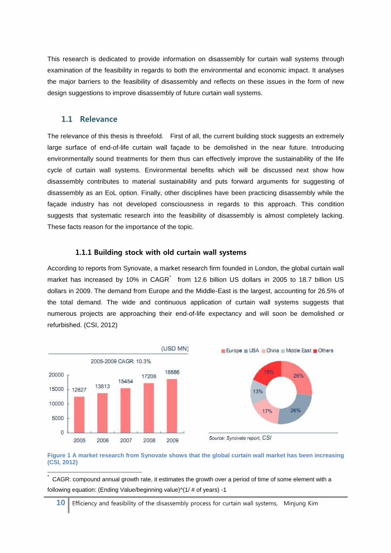
According to reports from Synovate, a market research firm founded in London, the global curtain wall
market has increased by 10% in CAGR* from 12.6 billion US dollars in 2005 to 18.7 billion US
dollars in 2009. The demand from Europe and the Middle-East is the largest, accounting for 26.5% of
the total demand. The wide and continuous application of curtain wall systems suggests that
numerous projects are approaching their end-of-life expectancy and will soon be demolished or
refurbished. (CSI, 2012)
Figure 1 A market research from Synovate shows that the global curtain wall market has been increasing (CSI, 2012)
* CAGR: compound annual growth rate, it estimates the growth over a period of time of some element with a
following equation: (Ending Value/beginning value)^(1/ # of years) -1

11 Efficiency and feasibility of the disassembly process for curtain wall systems, Minjung Kim
A study by T. Ebbert from 2009 on refurbishment strategies for office facades analyses the total office
stock and type of façade that is in need of refurbishment. According to his research, the office stock
constructed before 1978 accounts for roughly 604 million square meters in the assessed countries
(Italy, Germany, the UK, France and Spain). The report presents a ratio of GFA (gross floor area) to
façade surface of 55%.This suggests that the façade surface of office buildings older than 30 years
accounts for a minimum of 510 million square meters. According to the research’s spot check analysis
36% of the office façade types are curtain walling. From this data we can conclude that a minimum of
180 million square meters of curtain wall façades will be demolished in the near future.
The continuous construction and demolition of curtain wall façades illustrate the imperative search for
an environmentally sound end-of-life scenario for curtain wall systems.
1.1.2 Environmental benefit
There are various approaches to the end-of-life treatment of products. They can be listed according to
increasing environmental impact; reuse, recycling, energy recovery and landfill. The diversion rate† of
materials/components to a specific treatment depends on the choice for the end of life scenario for the
product, e.g. demolition versus disassembly.
Figure 2 Several EoL treatments; implementing disassembly extends possible waste options toward environmentally more favoured route.
In demolition all materials are considered waste, whereas the disassembly process is completely
separate from waste treatment. The conventional methods that are widely used include demolition.
This is because its relatively inexpensive nature and approach offer a swift method for clearing sites
for new structures. In the demolition process, however, the different types of debris are mixed and
† Diversion rate: the percentage of demolished materials diverted from traditional disposal in landfills and
incineration to recycling or reuse.

12 Efficiency and feasibility of the disassembly process for curtain wall systems, Minjung Kim
shredded, which leads to contaminated materials that are expensive to clean or separate. These
additional expenses often result in the down-cycling‡ of low value materials, which entails quality
degradation.
While the best treatment of demolished debris is recycling on the level of material, implementing
disassembly diverts them toward an environmentally more favoured route, i.e. reuse. Component
reuse saves energy for recycling and production. When done efficiently, it also encourages
maintenance and upgrade of curtain wall systems still in use which results in prolonged life
expectancy. Overall level of material recycling would be improved as homogeneity of materials
increases by separating components while they’re still intact. Therefore, several environmental
benefits are addressed by replacing the demolition approach with the disassembly approach in the
EoL scenario of curtain wall systems;
Reduction of virgin materials and minimizing of reprocessing energy use
Preservation of embodied energy and
Minimizing the amount of waste and land use for landfill by improving reusability and
recyclability.
Figure 3 Replacing demolition phase to disassembly phase encourages facilitation of some EoL treatments which entail less environmental burden than the conventional treatment.
‡ Down-cycling: the process of converting waste materials into new materials or products of lesser quality.

13 Efficiency and feasibility of the disassembly process for curtain wall systems, Minjung Kim
Figure 4 Disassembly takes apart components intact. It allows systematic reuse of components and encourages recycling by minimizing complex preparation activities.
1.1.3 Disassembly issue in other disciplines
Disassembly theory is not a new idea but has been developed across many disciplines. Ideas of
planning disassembly processes in an efficient manner started to come about with establishment of
large-scale slaughterhouses during the latter part of the 19th century. Public appeal for the
development of disassembly theory had been fuelled by the emergence of industrialization. Mass
production brought standardization of components and products for assembly lines for factories.
Disassembly of products was analysed as one of methods to improve efficiency of the assembly by
thinking in a reverse order. Otherwise disassembly is mainly practiced for maintaining and repairing
the products. End-of-life products were recycled as scrap or discarded for many years. (Gupta, 2004)
Growing environmental consciousness, however, has fuelled the discussion of disassembly methods
since the 1990s when exhaustion of resources and waste disposal rapidly accelerated. In various
countries and various fields, environmental legislations to reduce the amount of waste have been
introduced in the form of take-back systems for discarded products. A fee for the process of a
sustainable end-of-life treatment has to be paid in advance when customers purchase the products.
The process includes disassembly, shredding and material separation for recycling. The movement to
impose more responsibility to manufacturers for the EoL of their products appeared most obviously in
automotive and electronic industries.
European community (EC) countries issued directives for processing the EoL of products with targets
set to increase material retrieval to save virgin materials and reduce the amount of final waste going
to landfills. Disposal practice for the automotive industry is regulated via the Directive 2000/53/EC, the
End of Life Vehicles (ELV) directive, and the Directive 2002/96/EC, the Waste Electrical and
Electronic equipment (WEEE), is set for electronics. Governed by the directives, current reuse and
recycling level of discarded products are challenged to be raised to at least 85% by 2015 for cars and
by 2016 for electronics.(Gupta, 2004) Manufacturers are also required to build strategies for
disassembly into the design of their products. In the past designing products such as cars rarely

14 Efficiency and feasibility of the disassembly process for curtain wall systems, Minjung Kim
involved consideration of what processes would be assigned to take them apart. Achieving the targets
started with disassembly of some components that could be purchased as spare parts for reuse.
Profit from recycling materials which contain a large amount of valuable metals also turned out to be
increased by disassembly. These facts have converged to motivate disassembly practice in these
fields.
The facade industry, however, has not embraced the disassembly idea. The majority of stakeholders
and customers in the field do not have access to details of the EoL issue. For this reason, even if
environmental concerns or tightened regulations drive people to consider the option, demolition
continues to be preferred because it is a conventional method with accumulated knowledge. This
condition confirms the scientific value of this research to provide information of disassembly for the
facade industry especially focusing on curtain wall systems.
Figure 5 End-of- life vehicles and electronics (source: ec.europa.eu)

15 Efficiency and feasibility of the disassembly process for curtain wall systems, Minjung Kim
1.2 Objective
This research attempts to answer the following questions;
Research question
Does disassembly represent a feasible end-of-life scenario for curtain wall systems?
Design question
How can the design of curtain wall systems be optimized in order to facilitate disassembly
processes?
The objectives are;
1) To document information on end-of-life scenarios of curtain wall systems,
2) To describe jobsite practices such as sequencing, laying out of operations and tools and
their influence on labour productivity,
3) To analyse flow of materials and consequent environmental impact,
4) To determine economic and environmental feasibility of EoL scenarios,
5) To uncover barriers to facilitating disassembly for EoL curtain wall systems,
6) To improve disassembly of the curtain wall system to increase reusability, recyclability and
manageability,
7) To provide methods for decision making in product development concerning disassembly.
1.3 Methodology
The utilized methodology in the study comprises literature survey, LCA and LCC assessments, site
visits and interviews with representatives of key stakeholders in the Netherlands.
The study first will contribute to providing knowledge of different approaches for EoL curtain wall
systems. The purposes are (i) to find problems with disassembly as a common method and (ii) to
formulate EoL scenarios to be compared through environmental and economic assessments which
structure subsequent parts of the research. Common EoL scenarios for curtain wall systems are
identified by the literature study along with interviews with commercial contractors including an
aluminium recycling company(EMAX Billets, Kerkrade) and a demolition company(Beelen,
Harderwijk). The list of approaches is supplemented by disassembly as an alternative EoL treatment.
Processes of the scenarios are elaborated to illustrate their disparities. The analysis are carried out
under classification of job site activities and material flows in order to clarify important factors involved
in each scenario and the consequent influences. Interviews with commercial contractors (EMAX
Billets Kerkrade, Beelen Harderwijk, APT Manheim, VERAS and IVAM) and a site visiting (APT
Manheim) are combined to make the details more affluent.
16 Efficiency and feasibility of the disassembly process for curtain wall systems, Minjung Kim
The following study will concentrate on demonstrating the environmental benefits of disassembly and
its economic impact by means of competitive assessments. A goal of the assessment is to determine
the feasibility of disassembly. Different EoL scenarios are formulated based on information from the
prior research phases. Other scenarios which feature common methods are compared to the
disassembly scenario in regards to their cost and environmental load. The competitive assessments
are done using a method of Life-Cycle-Assessment (LCA) for evaluating the environmental impact
and Life-cycle-costing (LCC) for the economic impact. Principles and application methods of LCA are
provided from several studies including (Fleur van Broekhuizen, 2010),(M.Asif, 2007),(Beatriz Rivela,
2005) and Ecoinvent reports:(Martin Lehmann, 2007),(Hans-Jorg Althaus, 2009),(Michael Spielmann,
2007) and (Gabor Daka, 2009). Discussion with a Ph.D. student, Dipl.-Ing. Linda Hildebrand from the
Department of Architectural Engineering and Technology at Delft university of Technology,
supplements the method. The LCC method is formed based on research by Symonds (1999).
In design phase, strategies to improve disassembly are addressed in regards of the problems arose
during the research phase. A design concept is suggested and assigned challenges are discussed to
develop the design. Experts from Alcoa Architectuursystemen, Harderwijk, provide technical input for
the development. Finally, application examples will be given to define potentials and conditions
required for the design.
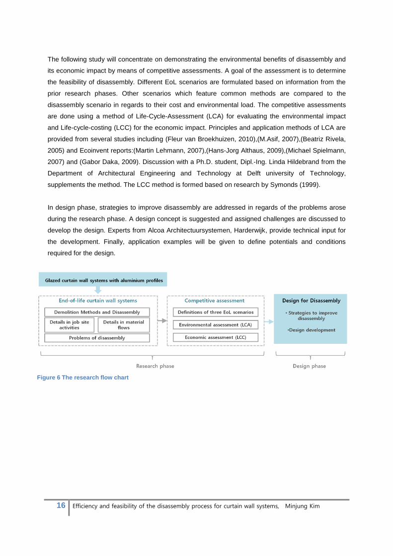
Figure 6 The research flow chart

17 Efficiency and feasibility of the disassembly process for curtain wall systems, Minjung Kim
1.4 Scope
1.4.1 Material
Curtain wall systems may incorporate a variety of materials. The research, however, is limited to
certain materials; the most dominant type of glazed curtain wall system is studied. This system
consists of mullions and transom of aluminium extrusion and cladding of vision or spandrel glazing
units.
- Aluminium profile: Despite the great number of available alloys of aluminium, characteristics
of some alloys limit the application to curtain wall systems. The research thus considers few
types of aluminium alloys often used; 6060, 6061 and 6062.
- Glazing unit: Taking advantage of its transparency, glass has been the most popular facing
material for curtain wall system. Glass has additional important characteristic that make it
suitable for outdoor condition. It is hard, dense, incombustible and resistant to abrasion and
weathering. Although there are varying possibilities for glass products with textures, colours
and performance, Insulated Glazing Units (IGUs) are typically placed as cladding elements to
achieve good thermal performance to protect the interior climate. They consist of double glass
layers for most cases and a gas filled in the intermediate space in order to reduce heat loss.
The edge is finished with glue and spacer which is made of aluminium or plastic. Typical
configurations of IGU are illustrated in figure 7.
Figure 7 A typical configuration of a double glazing (Ch.F.Hendriks & Janssen, 2001)
Figure 8 The research scope is limited in the standard type of glazed curtain wall system with
aluminium profiles (Alcoa-architectuursystemen)

18 Efficiency and feasibility of the disassembly process for curtain wall systems, Minjung Kim
1.4.2 System
Conventionally, there are two basic categories of curtain walling installations: Stick and Unitised.
Each method offers advantages and disadvantages.
Stick systems are installed on site with standard components in knock down form [Figure 9, left]. It
allows site adjustment and flexibility in sudden design changes. Thus it features economic and
reliable method to install curtain walling. However, they are slow to assemble due to a large list of job
site activities and the quality of installation is vulnerable to uncontrolled weather condition or labour
skill. (Kawneer, 1999).
On the other hand, unitised curtain wall systems are installed as a series of factory-assembled frames
which appear as complex window systems [Figure 9, right]. The method forms a suitable approach for
fast projects with limited building site because they have major benefits in reduction of installation
time and consequent labour cost. Achievement of high product quality is viable with carrying out entire
manufacturing processes in factory. Storage and shipping costs, however, are increased as well as
the cost for lifting equipment on site. (Kawneer, 1999).
Figure 9 (left) A stick system is installed on site with standard components in knock down form and (right) a unitized system is constructed as a series of factory-assembled. (Ulrich Knaack, 2007)
The stick systems define the scope of this research in regards to the construction method. Despite its
advantages of unitized systems, such as high production quality and rapid assembly, the use has
been limited to special applications in reality such as high-rise buildings. The reasons include that the
elements typically are more complex and expensive. In addition, mounting units on the shell of the

19 Efficiency and feasibility of the disassembly process for curtain wall systems, Minjung Kim
building must be installed with extensive planning of the structural joints and accuracy because
permissible tolerances of the shell of the building are limited. (Ulrich Knaack, 2007) The
disadvantages of the unitized system result that the stick system take a dominant position in the
market of curtain wall systems.
There are mainly three types of application of stick systems; Standard continuous glazing, Semi-
structural glazing and Structural glazing.
Figure 10 Three main applications of curtain wall system: (1)Standard continuous glazing, (2)Semi-structural glazing and (3) Structural glazing
Although they appear different from outside, all applications of the curtain wall system adopts a
standardized design. The design can be modified depending on manufactures however the principle
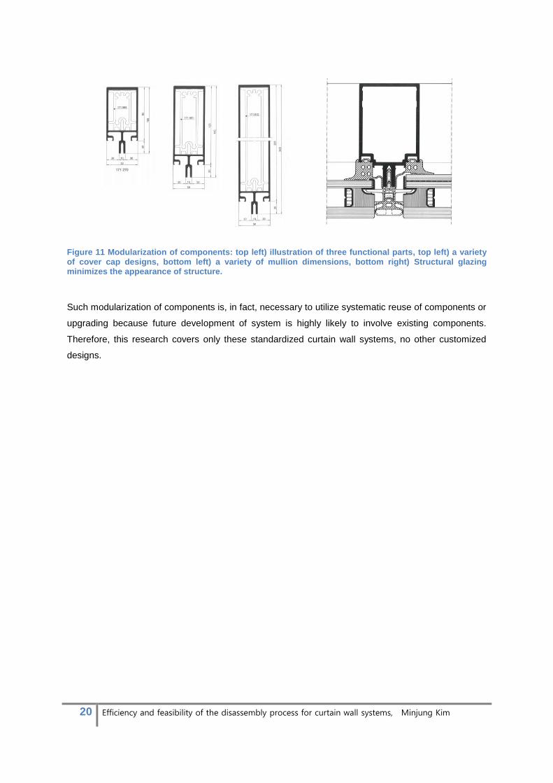
to screen elements out buildings remains same. There are tree functional parts; a) Mullion takes up
wind pressure on the façade surface, b) Fixation connects several layers to keep water and air out
and c) Cover cap has only aesthetic function. The dimension of mullion would be changed by
outcome of structural calculation and cover cap would be designed in consideration of desired
appearance or even removed. Nevertheless, the fixation remains the same in any case.
a. Mullion:
Structural function
b. Fixation:
Protect building from
elements
c. Cover cap:
Aesthetic function
20 Efficiency and feasibility of the disassembly process for curtain wall systems, Minjung Kim
Figure 11 Modularization of components: top left) illustration of three functional parts, top left) a variety of cover cap designs, bottom left) a variety of mullion dimensions, bottom right) Structural glazing minimizes the appearance of structure.
Such modularization of components is, in fact, necessary to utilize systematic reuse of components or
upgrading because future development of system is highly likely to involve existing components.
Therefore, this research covers only these standardized curtain wall systems, no other customized
designs.
21 Efficiency and feasibility of the disassembly process for curtain wall systems, Minjung Kim
2. End-of-life of curtain wall systems
2.1 Demolition methods and disassembly
This section focuses to give descriptions of different methods to approach to EoL of curtain walling.
The descriptions include mechanisms of removing and the required conditions for the use. Common
methods to process the EoL of curtain wall systems will be identified in this section. The identification
is necessary to formulate EoL scenarios to be compared to the disassembly scenario during
competitive assessments for the subsequent part. Information of the methods was gathered by
literature studies and Kees van Es, CEO of Beelen Harderwijk, who was interviewed to confirm the
information.
Demolition methods were learned from “Code of Practice for Demolition of Buildings,2004” which
outlines good practices for the planning and implementation of demolition works for different types of
buildings (Building-department, 2004) The methods can be divided into four major categories;
• Manual Method (using smaller equipment which can work between floors and hand tools),
• Mechanical demolition(involves the use of large machinery to demolish the building from
outside),
• Wrecking ball (Destruction by impact of steel ball suspended from a crane) and
• Implosion (Using explosives)
Wrecking ball and implosion methods were widely used in the period from 1970 to 1985 when
demolition waste was not recycled. However, its impact on the surrounding area through noise and
vibration limited their use in the present (Ch.F.Hendriks & Janssen, 2001). The common demolition
method has been changed to improve waste recovery due to increasing awareness of environmental
issues. Currently, demolition methods are limited to manual methods and mechanical demolitions for
this reason.
Studies by the European Aluminium Association (EAA) for “Collection of Aluminium from Buildings in
Europe” (2004) and by the Building department for “Code of Practice for Demolition of Buildings”
(2004) offer information on common demolition methods for building with curtain walling. An interview
with Beelen Harderwijk, a certified demolition company in the Netherlands, confirmed the data.
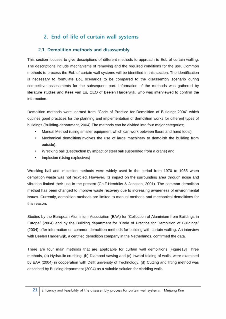
There are four main methods that are applicable for curtain wall demolitions [Figure13] Three
methods, (a) Hydraulic crushing, (b) Diamond sawing and (c) Inward folding of walls, were examined
by EAA (2004) in cooperation with Delft university of Technology. (d) Cutting and lifting method was
described by Building department (2004) as a suitable solution for cladding walls.
22 Efficiency and feasibility of the disassembly process for curtain wall systems, Minjung Kim
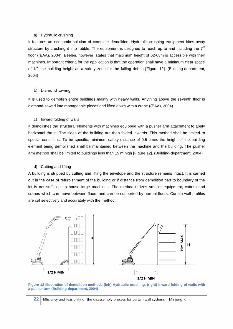
a) Hydraulic crushing
It features an economic solution of complete demolition. Hydraulic crushing equipment bites away
structure by crushing it into rubble. The equipment is designed to reach up to and including the 7th
floor ((EAA), 2004). Beelen, however, states that maximum height of 62-68m is accessible with their
machines. Important criteria for the application is that the operation shall have a minimum clear space
of 1/2 the building height as a safety zone for the falling debris [Figure 12]. (Building-department,
2004)
b) Diamond sawing
It is used to demolish entire buildings mainly with heavy walls. Anything above the seventh floor is
diamond-sawed into manageable pieces and lifted down with a crane.((EAA), 2004)
c) Inward folding of walls
It demolishes the structural elements with machines equipped with a pusher arm attachment to apply
horizontal thrust. The sides of the building are then folded inwards. This method shall be limited to
special conditions. To be specific, minimum safety distance of 0.5 times the height of the building
element being demolished shall be maintained between the machine and the building. The pusher
arm method shall be limited to buildings less than 15 m high [Figure 12]. (Building-department, 2004)
d) Cutting and lifting
A building is stripped by cutting and lifting the envelope and the structure remains intact. It is carried
out in the case of refurbishment of the building or if distance from demolition part to boundary of the
lot is not sufficient to house large machines. The method utilizes smaller equipment, cutters and
cranes which can move between floors and can be supported by normal floors. Curtain wall profiles
are cut selectively and accurately with the method.
Figure 12 illustration of demolition methods (left) Hydraulic crushing, (right) Inward folding of walls with a pusher arm (Building-department, 2004)

23 Efficiency and feasibility of the disassembly process for curtain wall systems, Minjung Kim
Figure 13 Demolition methods (a) Hydraulic crushing, Up to and including the 7th floor, (b), Diamond sawing Above the 7th floor (c) Inward folding of walls, Alternative method to ensure optimal metal collection, (d)Striping, not demolished in their entirety, and (e)Disassembly, dismantle building components intact ( source of the first three diagrams: ((EAA), 2004))
Interview with Kees van Es from Beelen Company, prepared in May 3rd
2013, indicated two demolition
methods that are used most frequently for curtain wall systems.
According to the interview, most of EoL curtain wall systems are demolished by means of hydraulic
crushing when the circumstance allows. Short demolition hours and less man hours are the main
reasons for its popularity. For special occasions, however, cutting and lifting method is also used.
These occasions include; (1) The primary structure must remain intact for the purpose of renovation
of buildings by stripping out old curtain walling and (2) Requirement of minimum distance for
adequate operation for machinery jobs is not satisfied.
The list of EoL approaches shall be supplemented with disassembly as an alternative method for
curtain wall systems. As discussed in section 1.1, disassembly (e, in Figure 13) performs more
sustainable EoL scenario than demolition.
(e) Disassembly is not a common practice in the present. It shall make a reasonable option in some
conditions. For example, when there are considerable quantities of valuable materials to be collected
from exterior profiles, disassembly ensures optimal collection and recovery of the elements and

24 Efficiency and feasibility of the disassembly process for curtain wall systems, Minjung Kim
materials by precisely taking apart the components. In addition, when the old components possess
sale values as second-hand product, the curtain walling shall be disassembled to resell them. Lastly,
disassembly can be facilitated to increase recyclability for situations when mixed contaminants have
to be separated otherwise it leads to decreased recycling levels. Most of disassembly processes
generally are handled by manual labour for the high accuracy which is necessary to not leave any
damage on the components. Other benefits include minimum disturbance on the surrounding
because the disassembly process hardly generates noise or vibrations.
Figure 14 The University of Amsterdam (UVA) was striped out as a part of the renovation process. This project was delivered by BEELEN GROEP B.V
In conclusion, general EoL treatments for curtain wall systems consist of (1) Hydraulic crushing for
complete demolition and (2) Cutting and Lifting for selective demolition. The popularity is because of
short operation hours and less man hours. Disassembly is not practiced as a common EoL treatment
of curtain wall systems. Increasing environmental concerns in building industry, however, give rise to
a doubt of sustainable performance of conventional demolition methods and seek for more
sustainable EoL scenarios. Hence, for the near future, disassembly shall become an alternative
approach to demolition for its environmental benefits.
25 Efficiency and feasibility of the disassembly process for curtain wall systems, Minjung Kim
2.2 Demolition, Selective demolition and disassembly
Chapter 2.1 focused on demolition methods and disassembly that make three representative
approaches for EoL curtain wall systems. This chapter will concentrated on the details of the three
methods; Demolition, Selective demolition and Disassembly. Demolition designates Hydraulic
crushing methods as it is utilized for complete demolition and selective demolition designates Cutting
and lifting for the same reason. Job site activities and material flow of the three approaches will be
discussed to give the characteristics in detail. Job site activities would show a list of assigned tasks
and work efficiency as determinants of schedule and payments. Material flows would define
possibilities in recovery of material and components by each treatment that will be criteria to assess
the environmental burden. The detail will allow distinguishing problems on implementing disassembly
in relation to other common methods. Another purpose of this chapter is to give background
knowledge to build EoL scenarios for competitive assessments that will be discussed in the chapter 3.
2.2.1 Job site activities
There were several studies to analyze jobsite practices, such as sequencing, layout of operation and
tools. NAHB RESEARCH CENTER, INC.(1997) used four categories to subdivide the jobsite
practices on the research of “Deconstruction-Building Disassembly and Material Salvage: The
Riverdale Case Study”. The four categories are disassembly, processing, production support and
non-production. On the other hand, for the research of “Building Deconstruction: Reuse and Recycling
of Building Materials”, the Centre for Construction and Environment (CCE) subdivided site activities
into five categories: Supervision, deconstruction, demolition, processing, non-production, cleaning-up/
disposal and loading/unloading.
This research uses a combined classification; Disassembly, Demolition, Processing, Production
Support and Non-Production. From definitions by two researches, the supervision and the last two
categories from CCE study could be merged under production support category. Deconstruction and
disassembly designate the same activities, thus the term “disassembly” was selected.
A. Disassembly: careful separation into its different parts,
B. Demolition: detachment from the structural system with damage to its components.
C. Processing: cleaning, sorting, manual inspection of materials, stocking, moving materials to
storage location and loading for further processing,
D. Production support: supporting activities of demolition or disassembly execution like
supervision, erecting working station, insuring for passage, storage and transportation, etc.
E. Non-production: down-time associated with job site activities and research (Idle, breaks,
research monitoring, etc)
With the categorization, job site activities from three EoL treatments can be analyzed in detail.

26 Efficiency and feasibility of the disassembly process for curtain wall systems, Minjung Kim
2.2.1.1 Job site activities of demolition project including curtain walling
Here, demolition of curtain wall systems indicates complete demolition of the entire building including
curtain wall systems by means of the hydraulic crushing (refer to section 2.1).
A. Disassembly: Presence of hazardous and semi-hazardous materials should be investigated and
disassembled by strictly regulated procedures. The hazardous materials generally are found in
the interior part of buildings that include insulations, air conditioning facilities, and ceilings and so
on. ((EAA), 2004) Thus, the mandatory stripping of all hazardous materials may not happen
during selective demolition and disassembly of curtain walling
B. Demolition: Except for special applications, complete demolitions with hydraulic crushing method
are operated from the top floor downwards to ensure stability of the structure.
C. Processing: All types of demolished materials will fall on the ground and mix together. Separation
of the material can be processed either on site or off site. The following two conditions must be
satisfied for on-site sorting
Space and time are available on the job site
The available fixed processing plant is placed too far.
Benefits of sorting on site shall be weighed against a time-saving potential associated to sorting
off site. Benefits from sorting on site are;
Lower materials handling
Higher revenue from secondary materials
Lower transportation
Lower machinery capital costs
The benefits, which are mostly considered in monetary point of view, from on-site separation
would be ensured when there is high-value materials involved in the demolition
waste(Ch.F.Hendriks & Janssen, 2001) On the other hand, on-site sorting may be forced to
comply with some certifications regardless of the material values. Then, incentive sorting and
other processing are demanded on the job site. When materials are sorted on-site, they are
separated into different groups including broken concrete, rock, bricks, rubbles, asphalt, soft inert
materials and non-inert waste. Figure 15 shows the sorted materials which are stockpiled
separately for subsequent disposal or recycling
D. Production Support: Hoarding, Work station and covered walkway must be provided for safe work
environment. The precautionary measures are included in building appraisal for getting approval.
Some important criteria are listed below. .
i. Extent the range of reach of the crusher: Debris may be used to build up a platform for the
hydraulic crusher to extend the range of reach if necessary. The debris should be densely
compacted and the height of the platform should not be over 3m to ensure safe manoeuvring
of the excavator(Building-department, 2004)
ii. Protect neighbours: Demolition of glazed curtain walling with a hydraulic crusher has the
potential to create dangerous situations with the flying glass debris. To secure the job site
from such situations, adjacent areas under the influence of the demolition work are covered
27 Efficiency and feasibility of the disassembly process for curtain wall systems, Minjung Kim
with rubber membranes in the maximum size of 8m X40m (width X height).§ The membranes
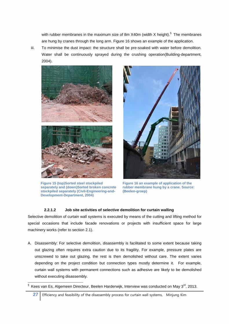
are hung by cranes through the long arm. Figure 16 shows an example of the application.
iii. To minimise the dust impact: the structure shall be pre-soaked with water before demolition.
Water shall be continuously sprayed during the crushing operation(Building-department,
2004).
Figure 15 (top)Sorted steel stockpiled separately and (down)Sorted broken concrete stockpiled separately (Civil-Engineering-and-Development-Department, 2004)
Figure 16 an example of application of the rubber membrane hung by a crane. Source: (Beelen-groep)
2.2.1.2 Job site activities of selective demolition for curtain walling
Selective demolition of curtain wall systems is executed by means of the cutting and lifting method for
special occasions that include facade renovations or projects with insufficient space for large
machinery works (refer to section 2.1).
A. Disassembly: For selective demolition, disassembly is facilitated to some extent because taking
out glazing often requires extra caution due to its fragility. For example, pressure plates are
unscrewed to take out glazing, the rest is then demolished without care. The extent varies
depending on the project condition but connection types mostly determine it. For example,
curtain wall systems with permanent connections such as adhesive are likely to be demolished
without executing disassembly.
§ Kees van Es, Algemeen Directeur, Beelen Harderwijk, Interview was conducted on May 3
rd, 2013.

28 Efficiency and feasibility of the disassembly process for curtain wall systems, Minjung Kim
a.Dismantling glazing
b.Taking out glazing c. Saw-cutting aluminium profile
d. Supervision
e.Prying out frames
f. Sorting aluminium profiles
g.Collecting
h.Shredder
Figure 17 Selective demolition processes for aluminium windows
B. Demolition: Curtain wall system shall be selectively demolished by hand held tools or small
machines which can work between floors. The manual demolition tool includes pry bar, saw,
hydraulic scissor and chain saw. When it contains concrete or stone, they shall be broken down in
small manageable pieces with hand tools or pneumatic jack hammers not heavier than 50kg. The
support structure may be cut off after all the panels are removed or when its support is no longer
needed. Selective demolition processes for aluminium windows are illustrated in figure 17.
29 Efficiency and feasibility of the disassembly process for curtain wall systems, Minjung Kim
C. Processing: In case of aluminium curtain wall systems, there are large quantities of aluminium to
be collected from exterior profiles. Therefore, sorting and processing of aluminium are likely to
take place on site to ensure the collection. Aluminium profiles are usually separated from other
material fractions at the time of cutting them. They would be transported to a shredder and a
sorting plant for further processing. The rest is treated as mixed demolition waste [Figure 17].
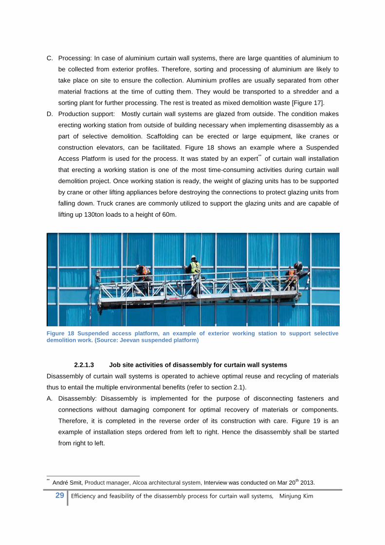
D. Production support: Mostly curtain wall systems are glazed from outside. The condition makes
erecting working station from outside of building necessary when implementing disassembly as a
part of selective demolition. Scaffolding can be erected or large equipment, like cranes or
construction elevators, can be facilitated. Figure 18 shows an example where a Suspended
Access Platform is used for the process. It was stated by an expert** of curtain wall installation
that erecting a working station is one of the most time-consuming activities during curtain wall
demolition project. Once working station is ready, the weight of glazing units has to be supported
by crane or other lifting appliances before destroying the connections to protect glazing units from
falling down. Truck cranes are commonly utilized to support the glazing units and are capable of
lifting up 130ton loads to a height of 60m.
Figure 18 Suspended access platform, an example of exterior working station to support selective demolition work. (Source: Jeevan suspended platform)
2.2.1.3 Job site activities of disassembly for curtain wall systems
Disassembly of curtain wall systems is operated to achieve optimal reuse and recycling of materials
thus to entail the multiple environmental benefits (refer to section 2.1).
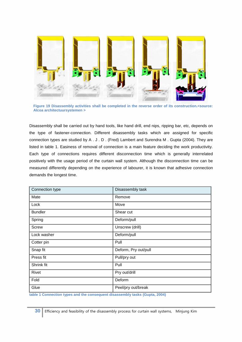
A. Disassembly: Disassembly is implemented for the purpose of disconnecting fasteners and
connections without damaging component for optimal recovery of materials or components.
Therefore, it is completed in the reverse order of its construction with care. Figure 19 is an
example of installation steps ordered from left to right. Hence the disassembly shall be started
from right to left.
** André Smit, Product manager, Alcoa architectural system, Interview was conducted on Mar 20
th 2013.
30 Efficiency and feasibility of the disassembly process for curtain wall systems, Minjung Kim
Figure 19 Disassembly activities shall be completed in the reverse order of its construction.<source: Alcoa architectuursystemen >
Disassembly shall be carried out by hand tools, like hand drill, end nips, ripping bar, etc, depends on
the type of fastener-connection. Different disassembly tasks which are assigned for specific
connection types are studied by A . J . D . (Fred) Lambert and Surendra M . Gupta (2004). They are
listed in table 1. Easiness of removal of connection is a main feature deciding the work productivity.
Each type of connections requires different disconnection time which is generally interrelated
positively with the usage period of the curtain wall system. Although the disconnection time can be
measured differently depending on the experience of labourer, it is known that adhesive connection
demands the longest time.
Connection type Disassembly task
Mate Remove
Lock Move
Bundler Shear cut
Spring Deform/pull
Screw Unscrew (drill)
Lock washer Deform/pull
Cotter pin Pull
Snap fit Deform, Pry out/pull
Press fit Pull/pry out
Shrink fit Pull
Rivet Pry out/drill
Fold Deform
Glue Peel/pry out/break
table 1 Connection types and the consequent disassembly tasks (Gupta, 2004)

31 Efficiency and feasibility of the disassembly process for curtain wall systems, Minjung Kim
Some connections wherein multiple components are joined in a certain sequence require complicated
tasks to disassemble them. The AA100Q curtain wall system provides an example. It uses a shear
block which only allows assembly and disassembly of transom to mullion in one direction and the
interlocking component is not reachable once installation is completed [Figure20]. This type of
connection is likely to be removed by cutting them out if labourers are not aware of the appropriate
sequence of disassembly. [Figure 21]
Figure 20 AA100Q curtain wall system provides an example of a complicated connection. This type of connection allows one directional removal and the disassembly sequence shall be limited because components share an interlocking component (marked).
Figure 21 Interlocking component is not reachable once installation is completed. Connected components thus should be taken out in a certain sequence as it was installed.
B. Demolition: Some connections are not easy to be disassembled without incurring damage. It can
be either due to the type of connection like an example illustrated with figure 20 or abrasion
damage on connections occurred during the usage period. When too complex and time-
consuming tasks are expected, demolition shall be an alternative to disassembly for the part.
C. Processing: Before implementing disassembly activities, materials shall be identified with careful
inspection and planned to be separated carefully. A guide to deconstruction investigated by
Bradely Guy (2003) contains a list of guidelines about processing disassembled materials.
Here some elements were removed from the list for specific conditions for curtain wall systems.
• Everyone on the site should know where the reusable, recyclable, useless materials will go
on the site and the means to get it there.

32 Efficiency and feasibility of the disassembly process for curtain wall systems, Minjung Kim
• Understand and prepare specific outlets (contacts), general markets (advertisement) and
methods (equipment, labour, sub-contracts) for removal of all materials from site.
• Pre-selling materials help reduce the risk of committing to the disassembly and can save time
and energy in processing, transporting and storing materials.
• The use of recovered structural elements will involve regulatory oversight.
•Consider all materials and the possible market for them, even plants, landscape pavers, etc..
D. Production support: For production support activities of disassembly, common requirements are
applied for demolition and selective disassembly to ensure job site safety by supplying adequate
form of exterior working stations. However there shall be differences in the activities to secure
quality of disassembled materials. For example, smaller fixing is employed for temporary fixing of
glazing panels rather than large equipments. As a general practice, little aluminium fixing plates
are places immediately after taking out pressure plate to prevent glazing units from falling down.
[Figure 22]
Figure 22 (left) Pressure plates (dark blue) hold glazing panels. (Middle) When the pressure plates are removed, it is necessary to temporarily fix(orange) the glazing panels to protect them from falling down. (right) Small aluminium plates are used to hold the panes (source: Reynoldsconstruction.com>)
2.2.2 Material flow
Detached materials from building structure are transported for further processing from the site. There
are different ways to treat the materials and the destination is different depending the type, quantity
and quality of materials. Identification of general material inventory of curtain wall systems is
necessary in order to trace the route where materials may flow. Different treatments are detailed to
discuss the characteristics including the recovery rate, dissemination of the knowledge, utilization of
techniques and the trend in current practise.
2.2.2.1 Material composition and the presence
General characteristics of standard curtain wall systems which are considered in the research were
described in paragraph 1.4.1. They mainly consist of frame and insulated glazing unit (IGU) as seen
in figure 23. The frame includes mullion, transom, pressure plate, cover cap, gasket, thermal break,
bolt, shear block, glass load bearing component and accessories (structure reinforcement, fire

33 Efficiency and feasibility of the disassembly process for curtain wall systems, Minjung Kim
resistance and etc). Insulated glazing unit, generally, has double glass layers and gas filled in the
intermediate space (refer to paragraph 1.4.1).
Figure 23 standard curtain wall system composition
Components are subdivided in accordance with the material in table 2.
table 2 Components are subdivided in accordance with the material
Glass content is indicated as 80% weight of the total IGU. It is based on a study from Martin Lehmann
and Hans-Jorg Althaus (2007) that describes edge of IGU with double glazing weighs 20% of the total
IGU. As a good practice, the edge will be separated from 80% of glass to be managed via different
treatment. The spacing is often made of burnable materials, plastics in most of cases.
34 Efficiency and feasibility of the disassembly process for curtain wall systems, Minjung Kim
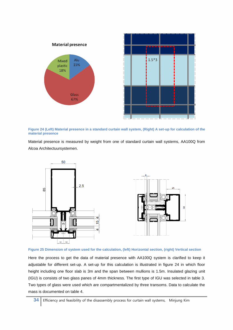
Figure 24 (Left) Material presence in a standard curtain wall system, (Right) A set-up for calculation of the material presence
Material presence is measured by weight from one of standard curtain wall systems, AA100Q from
Alcoa Architectuursystemen.
Figure 25 Dimension of system used for the calculation, (left) Horizontal section, (right) Vertical section
Here the process to get the data of material presence with AA100Q system is clarified to keep it
adjustable for different set-up. A set-up for this calculation is illustrated in figure 24 in which floor
height including one floor slab is 3m and the span between mullions is 1.5m. Insulated glazing unit
(IGU) is consists of two glass panes of 4mm thickness. The first type of IGU was selected in table 3.
Two types of glass were used which are compartmentalized by three transoms. Data to calculate the
mass is documented on table 4.

35 Efficiency and feasibility of the disassembly process for curtain wall systems, Minjung Kim
table 3 Characteristic of various type of glazing (Martin Lehmann, 2007)
table 4 Mass is calculated by : Sectional area X Length X Density. *Mass of IGU: Average mass of glass(20.1kg/m^2) X Surface area.
table 5 Conclusion of material presence calculation
The conclusive values are categorized according to three material groups; Aluminium, Glass and
Mixed plastics. The result of material presence for each group is shown on table 5. Other materials
in small quantities were excluded from the result. The conclusion shall be adjusted depending on the
choice of system and the dimension.

36 Efficiency and feasibility of the disassembly process for curtain wall systems, Minjung Kim
2.2.2.2 Material separation
Materials from EoL curtain wall systems shall be separated either on site or off site. The materials
would be separated on the site if the operation can be processed in cost-effective ways. Involvement
of materials which can be recovered and sold separately will make the operation effective. As a good
practice, wastes are separated into four categories. The categories are adopted from ‘Construction
and demolition waste: general process aspects’ investigated by Ch.F.Hendriks and Jassen (2011).
The contents are adjusted for the condition of curtain wall systems.
.
• Materials, ready for reuse without processing: IGU and aluminium profiles in good quality
• Materials to be recycled: Glass, aluminium (alloy 6060) and sorted plastic in large quantity
• Materials to be incinerated: mixed plastic and glazing edge with burnable spacing
• Materials not burnable, if not separated, it lowers the value of rest materials. For example,
other metal scraps in small amount are contaminants in recycling of glass or aluminium of
alloy 6060. They are sent to inert landfill.
Although it is difficult to prefer one option to another, it will be clear that reuse of waste is most
desirable, and landfill least desirable. Options listed below shall preferably be applied if options listed
above turn out to be impossible to realize.
2.2.2.3 Material treatment
Separated materials shall be directed to reuse, recycling, incineration or landfills. The four treatments
will be detailed in this section. The contents are organized by broad literature studies; ((EAA), 2004;
Althaus, Kellenberger, Classen, & Thalmann, 2007; Coventry, 1999; DWMA; EAA, 2007; Lehmann,
Althaus, & Empa, 2007; Lundgren, 2012; Paola Villoria Saez, 2011; W.Y.Tam, 2006). Emax Kerkrade
provided knowledge of aluminium recycling process via email. APT Manheim offered an opportunity to
visit the aluminium recycling plant and gather information by direct observation.
A. Reuse
In this process, components are used for the same purpose for which they were originally constructed.
It may involve reconditioning process for repair or alteration of some damaged original elements. For
reuse, new version of elements can replace the originals to improve its performance which is called
upgrading.
Aluminium profiles and insulated glazing unit may be reused in other buildings when they are in good
quality. Other material groups with high potential of property degradation due to ageing have to be
recycled. A major issue when reusing old curtain wall elements is that the performance of the old
system would not meet the present standard. It may be because the designed performance has
decreased during the used period or the requirement when it was installed was lower than the present.
The second-hand components, thus, would be exported to developing country with less strict
regulation. Otherwise reconditioning or upgrading processing often has to be accompanied.

37 Efficiency and feasibility of the disassembly process for curtain wall systems, Minjung Kim
Figure 26 An example of secondary window sale from the courthouse in Wuppertal, Germany ((EAA), 2004)
An investigation about collection of aluminium from buildings was conducted by European Aluminium
Association (2004). It documented an example of reuse of components from demolition project of the
courthouse in Wuppertal, Germany [Figure 26]. The courthouse of 17-storey tower office had been
built in the early 1960s and featured an extensive aluminium inventory in the window frames. The
windows were separated intact and sold to a buyer in Romania. The example indicates that there are
potential buyers of secondary building component in developing countries. Although the secondary
market does not seem to be trading secondary curtain wall components, discussions with curtain wall
experts from Alcoa Architectuursystemen suggest that reuse of second-hand curtain wall components
would be more feasible than used windows because the dimension can be adjusted flexibly while
window’ dimension is fixed.

38 Efficiency and feasibility of the disassembly process for curtain wall systems, Minjung Kim
B. Recycling
There is a broad range of recycling and recovery activities executed for demolished curtain wall
materials. Recovery rate of the materials varies by the choice of recycling method. Here general
methods of recycling are described for different materials.
1) Aluminium
There are two different aluminium scraps provided in aluminium recycling industry.
• New scrap: Surplus material from production or fabrication of aluminium products. It can be
remelted with little preparation because the quality and alloy are known.
• Old scrap: Post- consumer scrap. It comes back to aluminium industry via metal merchants
and waste management companies. There are usually shredding and sorting processes
involved, e.g. Magnetic, sink and float installation or eddy current installations.
Their involvement into an aluminium supply chain is illustrated in Figure 27 suggested by EAA
(2007).
Figure 27 Recycling of new and old aluminium scrap, old scrap is barely used in aluminium extrusion processes for curtain wall systems.
Gathered new and old scraps are cleaned chemically/mechanically, and isolated to minimize
oxidation losses when melted. Scraps are loaded into remelting furnaces and heated up to produce
molten aluminium. Dross is removed and the dissolved hydrogen is degassed from the furnaces.
(WNA, 2011) There are two major types of furnaces for the remelting processes.

39 Efficiency and feasibility of the disassembly process for curtain wall systems, Minjung Kim
(i) Furnace with two separated chambers and chimneys (Figure 28)
This technology is applied when contaminants on the scrap are vaporizable. First, scrap and raw
aluminium are placed inside of the remelting furnace in opposite side. Heat inside the furnace
vaporizes contaminants from the surface of scrap. The contaminants are released through
furnace chimney. Once contaminants are removed, the furnace is heated up till the melting point
of aluminium so that molten scrap and raw aluminium are mixed. (WNA, 2011)
Figure 28 Remelting Furnace with two separated chambers and chimneys(source: Alcoa Architectuursystemen)
(ii) Rotary furnace (Figure 29)
This technique is applied when the scrap is highly contaminated. Industrial salt is melted inside
furnace first and scrap is added. While heating and rotating furnace, melted contaminants are
separated from aluminium and mixed in salt liquid. Separated contaminants are coagulated with
salt when cooled down and become easy to screen out. (WNA, 2011)
Figure 29 Remelting scrap with rotary furnace (source: Alcoa Architectuursystemen)
After contaminants are removed by either way, melted aluminium undergoes spectrometer test to
identify the material composition. Other metals, such as copper, zinc, manganese and etc, are added
to alter the composition to the desired alloy specification. Then it is ready to be casted to ingots, slabs
or billets. The figure 30 and 31 illustrates liquid aluminium being released from furnace and the
resultant product in three different shapes.
40 Efficiency and feasibility of the disassembly process for curtain wall systems, Minjung Kim
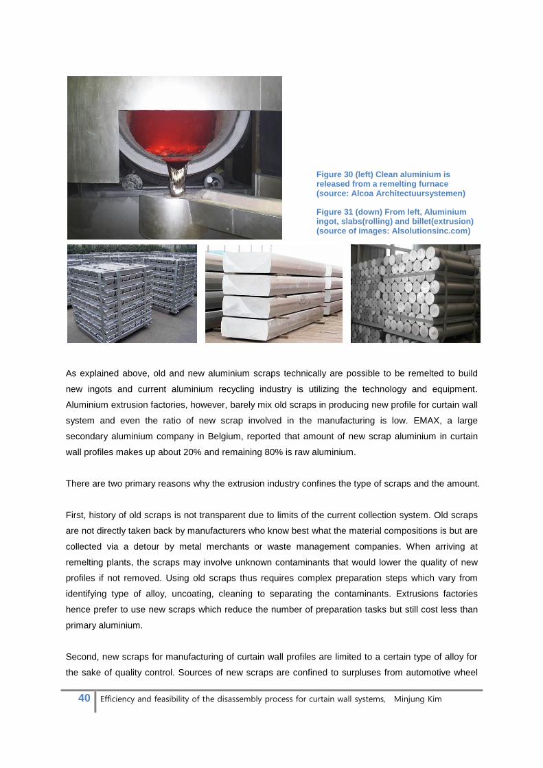
Figure 30 (left) Clean aluminium is released from a remelting furnace (source: Alcoa Architectuursystemen)
Figure 31 (down) From left, Aluminium ingot, slabs(rolling) and billet(extrusion) (source of images: Alsolutionsinc.com)
As explained above, old and new aluminium scraps technically are possible to be remelted to build
new ingots and current aluminium recycling industry is utilizing the technology and equipment.
Aluminium extrusion factories, however, barely mix old scraps in producing new profile for curtain wall
system and even the ratio of new scrap involved in the manufacturing is low. EMAX, a large
secondary aluminium company in Belgium, reported that amount of new scrap aluminium in curtain
wall profiles makes up about 20% and remaining 80% is raw aluminium.
There are two primary reasons why the extrusion industry confines the type of scraps and the amount.
First, history of old scraps is not transparent due to limits of the current collection system. Old scraps
are not directly taken back by manufacturers who know best what the material compositions is but are
collected via a detour by metal merchants or waste management companies. When arriving at
remelting plants, the scraps may involve unknown contaminants that would lower the quality of new
profiles if not removed. Using old scraps thus requires complex preparation steps which vary from
identifying type of alloy, uncoating, cleaning to separating the contaminants. Extrusions factories
hence prefer to use new scraps which reduce the number of preparation tasks but still cost less than
primary aluminium.
Second, new scraps for manufacturing of curtain wall profiles are limited to a certain type of alloy for
the sake of quality control. Sources of new scraps are confined to surpluses from automotive wheel
41 Efficiency and feasibility of the disassembly process for curtain wall systems, Minjung Kim
and aluminium profile industries wherein the same type of aluminium alloy is used. 6060 alloy
features the common type of aluminium. When remelting it to create the same alloy, only three
ingredients, magnesium, zinc or copper, are added to alter the molten composition to the proper alloy
specification. Otherwise the variety of materials included in different types of alloys complicates the
recycling processes. The quantity of available new scraps, however, is far from what is required to
produce curtain wall profiles using 100% recycled aluminium due to the limited sources of good scrap.
This condition results in the low rate of recycled aluminium involved in the manufacturing of curtain
wall profiles.
In conclusion, extrusion processes of curtain wall profiles employ only new scraps released from
certain industries to not risk the quality. The amount of recycled aluminium is limited because
demands of new curtain wall profiles are far above the new scrap supply. Old scraps are mostly
recycled into other aluminium applications.
2) Glass
Insulated glazing units come attached to metal or plastic spacer with glue. For recycling the IGU, the
rim containing other materials has to be handled separated otherwise the contaminants will degrade
quality of the recycled glass. IGU edges are cut out often by means of diamond-saw or the entirety is
sent to undergo shredding and sorting process. The process with sawing machines is labour
intensive and time-consuming, therefore glass sorting technologies have been invested to increase
the efficiency. (Martin Lehmann, 2007)
An example of the available glass sorting machines is provided by REDWAE, BT-Wolfgang Binder
GmbH, in Germany. The machine is capable of recovering three types of glass that include flint glass,
amber glass and green glass. The same number of sensor systems is required for the machine to
distinguish them. They include infrared, line scan camera and X-Ray Fluorescence technique.
(REDWAVE)
Despite the development of sorting technologies, unlike bottle glass which is recycled to bottle again,
float glass is not recovered to same product for the sake of quality. While bottle glass has a fairly
uniform composition, there is a broad range of float glass used in building industry; Tinted glass,
safety glass, tempered glass, etc. Each type has different characteristics of chemical composition and
melting temperature and so cannot be combined to create new glass. The condition leads to the
major challenge in float glass recycling; that the different subsets of building glass have to be
collected separately. The separation is either impossible or non-cost-effective with the available
techniques. Therefore the majority of float glass from the building industry is recovered to other
application.
42 Efficiency and feasibility of the disassembly process for curtain wall systems, Minjung Kim
• Glass fibre: For material properties enhancement, glass is recycled into glass fibre, which is
used in thermal and acoustic insulations, which can be added to strengthen cement, gypsum
or resin products. (Coventry, 1999)
• Filling material: United Kingdom practices recycled glass as a fine material for cement
replacement called “ConGlassCrete”, which is used for improving the strength of
concrete.(W.Y.Tam, 2006)
• Paving block: It is produced from recycled glass aggregate by crushing in USA. Hong Kong is
also developing this recycling technology, which can provide an attractive reflective
appearance on the surface after polishing, reduce water absorption of concrete block and
provide good compressive strength. (W.Y.Tam, 2006)
• Asphalt in road: Old glass is crushed into a very fine material in replacing asphalt. Taiwan
practices replaced 15% of the asphalt for recycled glass.
• Aggregate in road: crushed glass has been developed for use as an aggregate in bituminous
concrete pavement; popularly known as ‘glassphalt’ and it had been tested in USA. (Coventry,
1999)
• Foam glass: it is a thermal insulation product manufactured and distributed by Pittsburgh
corning Europe (PCE) and Pittsburgh corning corporation. It is mainly used as insulation
material throughout the building industry. Foam glass insulation materials are made from
recycled, mechanically cleaned float glass (68%) and feldspar (25%) in raw material quality.
Small amounts of technical grade quality salt cake, soda ash, iron oxide, manganese oxide,
sodium nitrate and carbon black are added to the raw material mix. Due to the market
monopoly of Foam glass, current technology for producing FOAMGLAS in EU is the
technology employed at the production site in Tessenderlo, Belgium. The manufacturing
processes are described in figure 32. (Althaus et al., 2007)
In conclusion, the loop of material flow of float glasses is not closed within building sector. Recycling
float glasses for the same use is unfeasible in the current technical framework. There is too broad
variety of float glass which should be separately collected. It causes hardship to achieve desired
performances of float glass with recycled cullet. Therefore float glass waste from EoL curtain wall
systems will gain their new life in different forms of products. Six current glass recycling techniques
were described in this section. “Foam Glass” which contains approximately 70% of float glass per
product seems to be providing the most efficient way.

43 Efficiency and feasibility of the disassembly process for curtain wall systems, Minjung Kim
Figure 32 Production of foam glass, plant Tessenderlo, Belgium (Althaus et al., 2007)
C. Incineration
There are some polymers which are recyclable in cost effective manners. Commonly recycled
polymers are listed by Geoffrey Pritchard in 1998. They include Polyethylene Terephthalate, Low and
High Density polyethylene, Polyvinyl Chloride, Polypropylene and Polystyrene. Other recyclable
polymers are polymethyl Methacrylate, polycarbonate, Nylons and Acrylonitrile-Butadiene-styrene.
(Pritchard, 1998)None of them, however, are applicable for production of curtain wall systems.
While recycling, when possible, is the preferred route, energy recovery through incineration is
probably the best currently available means of disposal for plastics that are too difficult to recycle.
(Mantia, 2002) From waste incineration, the surplus heat is recovered and used in the form of hot
water, steam and electricity. With benefits of space and water heating and power generation, Waste
to energy recovery complements conventional recycling.

44 Efficiency and feasibility of the disassembly process for curtain wall systems, Minjung Kim
A following table demonstrated by Francesco Paolo La Mantia in 2002 for investigation of plastic
recycling shows destination of plastics waste in EU during 1990. It indicates, excluding landfill,
majority of plastics waste are destined to incineration with heat recovery while maximum 1 per cent is
mechanically recycled.
table 6 Destination of plastics in Europe during 1990 (Mantia, 2002)
Dutch Waste Management Association (DWMA) stated on the official website their plan of waste-to-
energy treatment in the Netherlands. It describes Waste-to-energy plants, incineration with energy
recovery in other words, thermally treat residual waste that cannot be reused or recycled in an
economic or environmentally beneficial way. They are cost-effective and reliable sources of energy in
the form of electricity, district heating or cooling, and steam for industrial processes. The heat and
electricity delivered to housing and industry replaces fossil fuels used by conventional power plants.
Waste-to-energy plants therefore help to reduce CO2 emissions. (DWMA)
Once the recyclable element, such as glass and aluminium, has been removed from demolished
curtain wall systems, the residue can be incineration in number of ways: as MSW, RDF, PDF or
polymer fuel. These waste-derived fuels can be combusted on their own (mono-combustion) or
combined with conventional fossil fuel (co-combustion). The calorific value of these waste differs
depending on the type. MSW, Unsorted household waste, has an energy value of 10MJ/kg. Refuse-
45 Efficiency and feasibility of the disassembly process for curtain wall systems, Minjung Kim
derived fuel (RDF) that is produced by removing non-combustible components from MSW has energy
value of 15-17MJ/kg. One MJ is theoretically equivalent to the energy needed to power a 40W light
bulb for 7hours. (Mantia, 2002)
Swedish scientists, Eriksson and Finnveden (2009), studied the CO2 produced when unrecyclable
plastics are incinerated and the energy given off is recovered, compared with putting them into landfill.
Looking only at CO2 emissions, they concluded incineration of plastics produces a much greater
amount of CO2 than landfill. However, when incineration is performed with high-efficiency energy
recovery, it provides power normally generated by plants burning fossil fuels, and can produce less
CO2 than would otherwise have been released into the atmosphere, making the overall process CO2-
negative.(Eriksson & Finnvenden, 2009)
In conclusion, energy recovery through incineration provides the best currently available means of
disposal for plastics and other burnable residues from EoL curtain wall systems. DWMA has
investigated to accommodate the method in the waste treatment chain. Several preceding researches
demonstrated the benefits over putting the waste into landfill.
D. Landfill
A stricter control of landfill, for certain waste types of C&D waste, represents a major driver towards
better management. The disposal in landfills of the waste that can be incinerated and recycled is
forbidden in Denmark, the Netherlands and Germany. The Netherlands have a high rate of landfill
levy which is 83euro/t by a mean value of different types of waste. (Paola Villoria Saez, 2011)
In the Netherlands, the DWMA and several members are participating in the Sustainable Landfill
Foundation (Stichting Duurzaam Storten), which is investigating and testing various sustainable
landfill techniques. The foundation describes new landfill techniques on their official website that
environmentally damaging emissions shall be reduced to zero within a single generation. The new
techniques provide permanently safe landfills based on the idea of (i) breaking down pollutants into
harmless substances, (ii) flushing out pollutants before burning it and/or (iii) immobilising them in the
landfill. Research by the organization has shown that sustainable landfill is possible and delivers
better results than current methods.(Mathlener, Heimovaara, Oonk, Luning, & Sloot, 2006)
In conclusion, wastes which are not recyclable or burnable are landfilled in the Netherlands. Strict
control of landfill takes effect in forms of legislations and levies to reserve waste disposal capacity for
the future. Landfills, however, are an indispensable part of the waste management chain. Hence new
landfill technologies are investigated to minimize the impact from landfill.
.

46 Efficiency and feasibility of the disassembly process for curtain wall systems, Minjung Kim
2.2.2.4 Material flows of three EoL treatments
This section focuses to give descriptions of material flows of three EoL scenarios of curtain wall
systems; demolition, selective demolition and disassembly. Precede research of material treatments
will formulate the bases of the descriptions.
The three EoL treatments feature different amount of waste diverting to each waste options; reuse,
recycling, incineration and landfill. Demolition and selective demolition would develop a plan to
recover waste as much as possible in an effort to comply with environmental policies or certifications.
Loss of some material volume, however, is inevitable due to the characteristics of the operations that
reduce efficiency of material separation. Disassembly commonly separates materials at the highest
level among other scenarios with maximizing reuse potential of components.
Major characteristics of material flow of three scenarios are summarized below and illustrated with
figure 33, 34 and 35
• Reuse: Reuse is only applicable when implementing disassembly. The primitive purpose of
doing disassembly is to recover the maximum amount of materials for the highest reusability.
Material recovery through recycling may be a by-product in the case.
• Sorting: As a good practice, demolished materials are separated on site by the groups for
different destinations. There should be sufficient space available for the sorting process. The
sorting level of demolished materials on site, however, could not reach sufficient extent to
recycle them directly. Thus further shredding and sorting process should be followed for
material recovery. In case of selective demolition, only aluminium profiles shall be separated
in general because they guarantee high profit made by selling them. The rest of materials
shall be treated as mixed demolition waste. On the other hand, disassembly operation always
involves separation of materials at the same time with taking apart the components. It
enables direct transportation of separated materials to the adequate treatments from the
project site.
• Transportation: Disassembly project requires one necessary transportation process which
takes place to distribute materials after sorting on site. Sorted materials are headed directly
from the project site to reuse, recycling and incineration plants and when necessary to landfill
site. On the other hand, (selectively) demolished materials undergo two transportation
processes; 1) transportation to sorting and cleaning plant and 2) transportation to further
processing for separated material groups. Aluminium profiles in selective demolition scenario
will be excluded from the transportation step to sorting and cleaning plant.

47 Efficiency and feasibility of the disassembly process for curtain wall systems, Minjung Kim
Figure 33 Material flow of demolition scenario; Materials of demolished curtain wall systems shall be transported to shredding and sorting plant in the mixed entirety. After the process, materials will be distributed to recycling, incineration or landfill site separately. The optimal manner to recover material is material recycling in demolition scenario. However, as studied from previous chapters, any of materials from demolished curtain wall system cannot be recycled to same product again, thus there is no link to new curtain wall system.
Figure 34 Material flow of selective demolition scenario; Disassembly is implemented to take out glazing. Aluminium with high sale value is taken down and separated from other materials. Although glazing is disassembled intact for the sake of safety, it is mixed to other demolition waste because double glazing still requires to be shredded to separate the edge. Materials excluding aluminium undergo sorting process. Any of materials from this scenario are not recycled to curtain wall again.

48 Efficiency and feasibility of the disassembly process for curtain wall systems, Minjung Kim
Figure 35 Material flow of disassembly scenario; Disassembly targets achieving optimal recovery of materials by means of reuse. Thus components shall be collected separated without damaging them during the operation. Aluminium profiles and double glazing units in good quality shall be directed for reuse. Other separated materials are sent to recycling and incineration plant directly from the site. With disassembled aluminium profiles, it shall be possible to verify the quality and the composition which enables keeping the cycle of use for the same product. Double glazing edge shall be transported to incineration site after cutting out during the recycling process.
2.2.3 Barriers to implementing disassembly
Processes of three EoL scenarios for curtain wall systems were detailed in regard to the job site
activities and materials flows. Their characteristics were identified for the assigned tasks on site in
section 2.2.1 and the possible materials treatments in section 2.2.2. The information allowed defining
of the problems of the implementation of disassembly for curtain wall systems in relation to other two
approaches. Not unexpectedly, the main problems were found on the elements that increase
economic demand of the implementation. The problems and conceptual ideas of the solution will be
discussed below. Items from “a” to “d” are problems found in job site activities of disassembly
projects and “e” found in material flow.
a. Disassembly requires a complicated sequence
Disassembly is completed in the reverse order of the installation in the effort to minimize damage
on components. The process will be hampered when labours are not well-acquainted with the
sequence. Disassembly guidelines should be set out for workers to execute adequate sequence of
steps. Design for next curtain wall systems, otherwise, should attempt to simplify the disassembly
steps.
49 Efficiency and feasibility of the disassembly process for curtain wall systems, Minjung Kim
b. Complex connections preclude disassembly
Time consuming tasks are assigned for some types of connections, for example, where an
interlocking component shared by neighbours so that disassembly can be carried out only in a
certain sequence. If completing the tasks does not make sound economic sense, they are perhaps
removed by cutting. Decision on connection types, therefore, plays an important role in design
phase to optimize disassembly.
c. The production supporting tasks demand too much time and labours
Disassembly for curtain wall systems requires a list of the supporting tasks to ensure public and
labour security and to provide access for the operation. They are often too much labour and time
consuming. For example, some measures for holding glass panes should be placed when pressure
plates are taken apart during disassembly operation. In the most frequent practices, little aluminium
pieces are temporarily used to fasten glass panes to mullions and removed when removing glazing
units. Alternative glazing methods which do not necessitate such a series of works should be
discussed in order to effectively reduce disassembly execution time.
d. Network for trading second-hand components is not present for curtain wall systems
Revenue from disassembly activities can be guaranteed by pre-selling second-hand components
before committing disassembly. It brings lots of benefits in time and energy saving in the
processing. There is, however, no active market to sell or no firm network to advertise the trade.
Proper means to encourage the secondary market have to be discussed to realize economic
feasibility of disassembly scenario.
e. Absence of information system for second materials leads to down-cycling
For the components of curtain walling, there is no system to identify product characteristics
including material composition, mass, usage history and so on. It often leads to down-cycling of
secondary materials because manufacturers do not take the risk of quality degradation from
unknown contaminants. Aluminium recycling in curtain wall industry addresses a specific example,
wherein old scraps are not used in manufacturing new profiles although it is technically possible. A
system which tracks the history of the components and records material characteristic should be
suggested to improve the situation.
Specific strategies to solve the problems are necessary to realize feasible disassembly scenario for
curtain wall systems. They will be discussed in a design phase of the research for developing a
new curtain wall system of improved disassembly.
50 Efficiency and feasibility of the disassembly process for curtain wall systems, Minjung Kim
2.3 Conclusion of EoL curtain wall system
Section 2.1 identified are two common approaches for EoL curtain wall systems for the complete
demolition and the selective demolition. Disassembly was discussed as a mean to improve end-of-life
sustainability along with the other two. Section 2.2 detailed the three approaches in regard to the
assigned activities for the operations and traced the material streams.
The job site activities were described in paragraph 2.2.1. They were categorized into five categories
of demolition, disassembly, processing, production support and non production to clarify the source of
different characteristics of the three EoL approaches. The main disparity between them is found in
processing and production support categories. Descriptions of material processing activities for further
treatments revealed that intensive sorting processes occur on site for selective demolition and
disassembly scenarios. On the other hand, mixed materials released from demolition scenario are
roughly separated and sent to off-site shredding and sorting plants. In regard to production support
activities, while some common requirements exist for safety of the worker and the public, selective
demolition and disassembly implementation necessitate more complicated tasks to build exterior
workstations and to fix glazing units during the operations than demolition. Disassembly, especially,
demands more careful operations to ensure optimal recovery of released materials.
The material flows were demonstrated in paragraph 2.2.2. The types of materials and the composition
of curtain wall systems were identified first to trace the route where materials may flow. The four major
treatments of reuse, recycling, incineration and landfill were detailed in regard to the available
techniques, the recovery rate, and the trend of current practise and so on. Then possible treatments
for specific types of materials and scenarios were discussed. Figure 33, 34 and 35 illustrate the
conclusion in a clear way.
Finally, the information gathered from the study was combined to understand barriers to disassembly
implementation for curtain wall systems. The descriptions were given in paragraph 2.2.3.

51 Efficiency and feasibility of the disassembly process for curtain wall systems, Minjung Kim
3. Competitive assessment
The goal of this assessment is to assess feasibility of disassembly application for curtain wall systems
by estimating the environmental and economic impacts. The definitions of economic and
environmental feasibility are described;
Economic feasibility
The revenues of the total recovery process should be maximized within the constraints imposed
by legislature.
Environmental feasibility
The total amount of waste and its environmental loads should decrease when applying
disassembly.
The assessment is carried out by making comparisons to demolition scenarios which shall represent
common treatments. It is because although the assessment’s result is quantified for a disassembly
scenario, it will be hard to conclude the feasibility without proposing a standard.
There are three scenarios to be compared; Demolition, selective demolition and disassembly. The
scenarios were built based on knowledge gathered through previous chapters. The essentials are
given below. Referring to figure 33, 34 and 35 of material flows will help in understanding the
scenarios.
(1) Demolition Scenario: Complete demolition is carried out using hydraulic crushers. The
crushers grab building materials and take them away by applying force. Materials are
dropped on the ground and mixed during the operation. As a good practice, they are
separated into groups in accordance to the destinations for further processing. The materials,
however, should undergo additional shredding and sorting processes to be recovered
because the demolition activities make them difficult to be fully separated.
(2) Selective Demolition Scenario: Curtain wall systems are separately cut off from the structure.
Small hand tools or machines are employed for the operation. Disassembly is practised to
some extent to remove glazing units due to their fragility. The rest is destroyed to speed up
the operation. Aluminium profiles are separated from other waste groups to sell them for a
profits. Other materials are transported to shredding and sorting plants.
(3) Disassembly Scenarios: All components are taken apart and separated with care to
maximize their potential for reuse. Machinery works are restricted to minimize damage on the
components. Aluminium profiles and IGU of good quality will be recovered for reuse. Other
materials will directly head to recycling or incineration plants from the site.
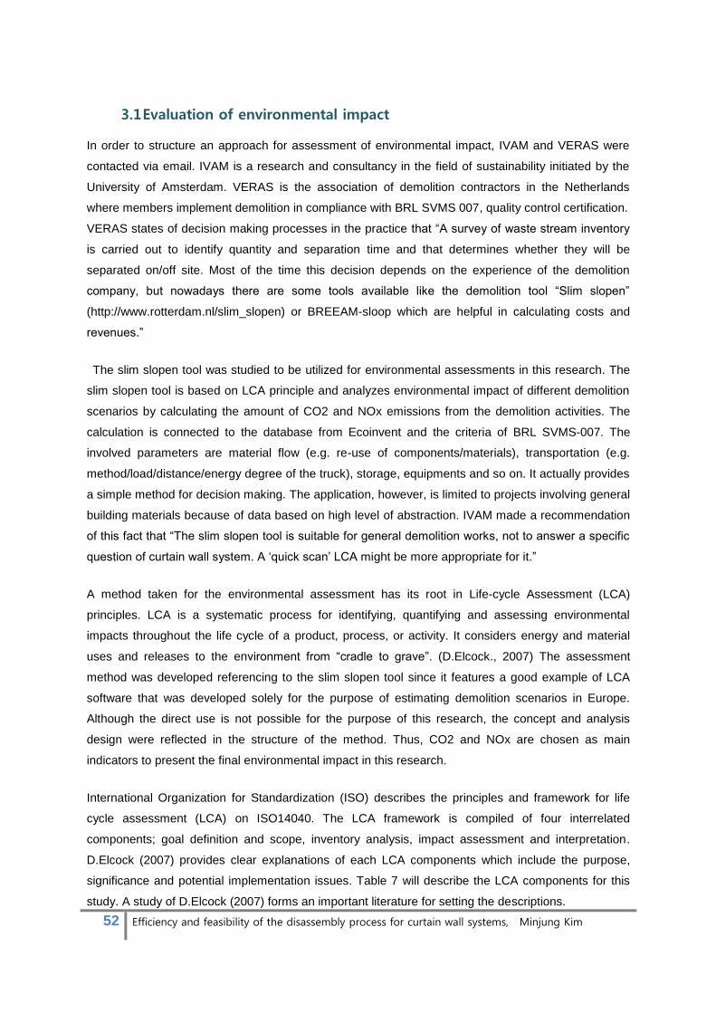
52 Efficiency and feasibility of the disassembly process for curtain wall systems, Minjung Kim
3.1 Evaluation of environmental impact
In order to structure an approach for assessment of environmental impact, IVAM and VERAS were
contacted via email. IVAM is a research and consultancy in the field of sustainability initiated by the
University of Amsterdam. VERAS is the association of demolition contractors in the Netherlands
where members implement demolition in compliance with BRL SVMS 007, quality control certification.
VERAS states of decision making processes in the practice that “A survey of waste stream inventory
is carried out to identify quantity and separation time and that determines whether they will be
separated on/off site. Most of the time this decision depends on the experience of the demolition
company, but nowadays there are some tools available like the demolition tool “Slim slopen”
(http://www.rotterdam.nl/slim_slopen) or BREEAM-sloop which are helpful in calculating costs and
revenues.”
The slim slopen tool was studied to be utilized for environmental assessments in this research. The
slim slopen tool is based on LCA principle and analyzes environmental impact of different demolition
scenarios by calculating the amount of CO2 and NOx emissions from the demolition activities. The
calculation is connected to the database from Ecoinvent and the criteria of BRL SVMS-007. The
involved parameters are material flow (e.g. re-use of components/materials), transportation (e.g.
method/load/distance/energy degree of the truck), storage, equipments and so on. It actually provides
a simple method for decision making. The application, however, is limited to projects involving general
building materials because of data based on high level of abstraction. IVAM made a recommendation
of this fact that “The slim slopen tool is suitable for general demolition works, not to answer a specific
question of curtain wall system. A ‘quick scan’ LCA might be more appropriate for it.”
A method taken for the environmental assessment has its root in Life-cycle Assessment (LCA)
principles. LCA is a systematic process for identifying, quantifying and assessing environmental
impacts throughout the life cycle of a product, process, or activity. It considers energy and material
uses and releases to the environment from “cradle to grave”. (D.Elcock., 2007) The assessment
method was developed referencing to the slim slopen tool since it features a good example of LCA
software that was developed solely for the purpose of estimating demolition scenarios in Europe.
Although the direct use is not possible for the purpose of this research, the concept and analysis
design were reflected in the structure of the method. Thus, CO2 and NOx are chosen as main
indicators to present the final environmental impact in this research.
International Organization for Standardization (ISO) describes the principles and framework for life
cycle assessment (LCA) on ISO14040. The LCA framework is compiled of four interrelated
components; goal definition and scope, inventory analysis, impact assessment and interpretation.
D.Elcock (2007) provides clear explanations of each LCA components which include the purpose,
significance and potential implementation issues. Table 7 will describe the LCA components for this
study. A study of D.Elcock (2007) forms an important literature for setting the descriptions.

53 Efficiency and feasibility of the disassembly process for curtain wall systems, Minjung Kim
Component Purpose/Results Significance/Results/Benefits
Goal definition
and Scope
Defines purpose of study. Sets
boundaries. Establishes functional
unit.
Depends on subject and intended use of the study.
Sets stage for entire analysis, including quality
assurance.
Breadth and depth of the study can vary considerably
depending on the goal.
Life-cycle
Inventory (LCI)
Provides inventory of input/output
data of the system under study.
Data are collected to meet the goals of the study.
Life-cycle impact
Assessment
(LCIA)
Provides information to understand
and assess the magnitude and
significance of the potential
environmental impacts associated
with the inventory results.
Provides a system-wide perspective of environmental
and resource issues.
Life-cycle
Interpretation
Provides conclusions and
recommendations based on the
results of the inventory and impact
assessments.
Uses a systematic approach to identify, evaluate, and
present conclusions to meet the requirements
described in the goal and scope.
table 7 LCA Components (Alcoa-architectuursystemen)
3.1.1 Goal definition and Scope
The goal of this LCA is to demonstrate environmental benefits driven by implementing disassembly in
the end-of life of curtain wall systems. Impacts from demolition and selective demolition application
are analyzed at the same time to propose a standard and clarify the improvement. The result would
give public information of potential improvement in sustainability of EoL scenarios for curtain wall
systems by selecting different EoL options prospectively.
The scope identifies the product system or process to be studied, functional unit, system boundaries
and assumptions.
3.1.1.1 The product system
It consists of a set of unit processes involved in a specific part of a life cycle of standard curtain
wall systems. The standard curtain wall system of which a description was given in paragraph 2.3.2
is studied for the assessment. The product system in this assessment covers “grave-to-gate” flows
where inputs and outputs are limited within the range from the point where demolition/disassembly
is executed to the point where waste recovery is completed.
3.1.1.2 The functional unit
It provides a quantitative reference of inputs and outputs. Two functional units are related in this
assessment that includes kg of CO2 and NOx. More sensible cases would involve other types of
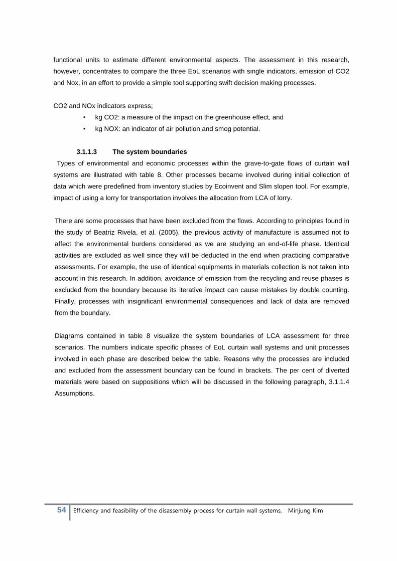
54 Efficiency and feasibility of the disassembly process for curtain wall systems, Minjung Kim
functional units to estimate different environmental aspects. The assessment in this research,
however, concentrates to compare the three EoL scenarios with single indicators, emission of CO2
and Nox, in an effort to provide a simple tool supporting swift decision making processes.
CO2 and NOx indicators express;
• kg CO2: a measure of the impact on the greenhouse effect, and
• kg NOX: an indicator of air pollution and smog potential.
3.1.1.3 The system boundaries
Types of environmental and economic processes within the grave-to-gate flows of curtain wall
systems are illustrated with table 8. Other processes became involved during initial collection of
data which were predefined from inventory studies by Ecoinvent and Slim slopen tool. For example,
impact of using a lorry for transportation involves the allocation from LCA of lorry.
There are some processes that have been excluded from the flows. According to principles found in
the study of Beatriz Rivela, et al. (2005), the previous activity of manufacture is assumed not to
affect the environmental burdens considered as we are studying an end-of-life phase. Identical
activities are excluded as well since they will be deducted in the end when practicing comparative
assessments. For example, the use of identical equipments in materials collection is not taken into
account in this research. In addition, avoidance of emission from the recycling and reuse phases is
excluded from the boundary because its iterative impact can cause mistakes by double counting.
Finally, processes with insignificant environmental consequences and lack of data are removed
from the boundary.
Diagrams contained in table 8 visualize the system boundaries of LCA assessment for three
scenarios. The numbers indicate specific phases of EoL curtain wall systems and unit processes
involved in each phase are described below the table. Reasons why the processes are included
and excluded from the assessment boundary can be found in brackets. The per cent of diverted
materials were based on suppositions which will be discussed in the following paragraph, 3.1.1.4
Assumptions.
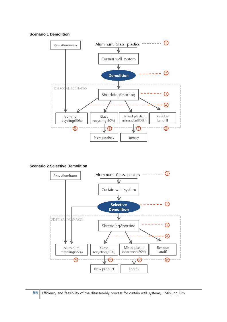
55 Efficiency and feasibility of the disassembly process for curtain wall systems, Minjung Kim
Scenario 1 Demolition
Scenario 2 Selective Demolition
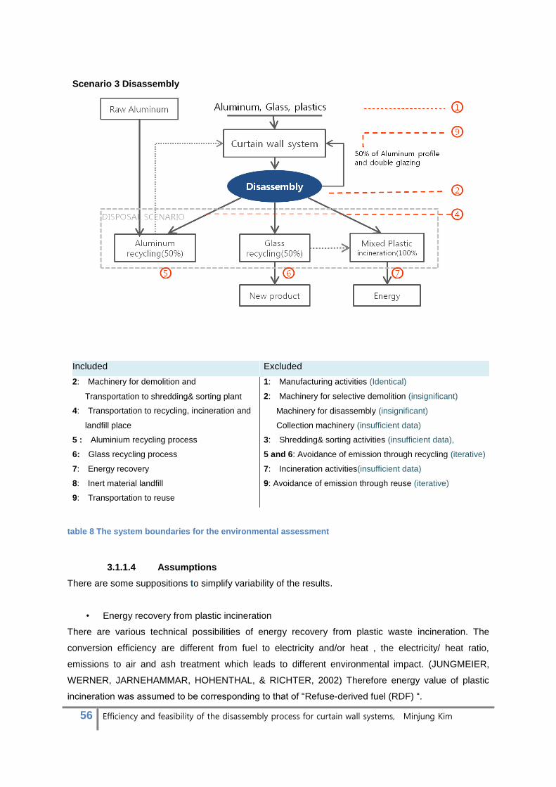
56 Efficiency and feasibility of the disassembly process for curtain wall systems, Minjung Kim
Scenario 3 Disassembly
Included Excluded
2: Machinery for demolition and
Transportation to shredding& sorting plant
4: Transportation to recycling, incineration and
landfill place
5 : Aluminium recycling process
6: Glass recycling process
7: Energy recovery
8: Inert material landfill
9: Transportation to reuse
1: Manufacturing activities (Identical)
2: Machinery for selective demolition (insignificant)
Machinery for disassembly (insignificant)
Collection machinery (insufficient data)
3: Shredding& sorting activities (insufficient data),
5 and 6: Avoidance of emission through recycling (iterative)
7: Incineration activities(insufficient data)
9: Avoidance of emission through reuse (iterative)
table 8 The system boundaries for the environmental assessment
3.1.1.4 Assumptions
There are some suppositions to simplify variability of the results.
• Energy recovery from plastic incineration
There are various technical possibilities of energy recovery from plastic waste incineration. The
conversion efficiency are different from fuel to electricity and/or heat , the electricity/ heat ratio,
emissions to air and ash treatment which leads to different environmental impact. (JUNGMEIER,
WERNER, JARNEHAMMAR, HOHENTHAL, & RICHTER, 2002) Therefore energy value of plastic
incineration was assumed to be corresponding to that of “Refuse-derived fuel (RDF) “.

57 Efficiency and feasibility of the disassembly process for curtain wall systems, Minjung Kim
• Glass recycling
Glass cullet can be recycled to many products. The final products determine energy consumption and
environmental impact in different amount. In this research, all cullet is assumed to be used in
manufacturing of Foam glass.
• Transportation
It is assumed that materials are transported by Lorries of European emission level of 3.
• Method of electricity generation
Technologies to generate electricity are various. Types of fuels vary from Nuclear, Coal, Natural Gas,
Oil, Solar Photovoltaic, Biomass and Hydroelectric to Wind. This research assumes all electricity use
occurred during processes are provided by means of Natural gas power.
• Diversion rate
Practical data of material diversion rate is not available. The research assumes different diversion rate
for three scenarios.
Figure 36 Assumption of material diversion rate from three scenarios
Aluminium collection rate for the selective demolition was estimated based on the EAA study (2004).
The study concluded that an average of 95% of collection rate was achieved for aluminium from
projects in 6 European countries (U.K., Germany, Spain, Italy, the Netherlands and France). A lower
aluminium collection rate was estimated for the demolition scenario because some material loss will
occur during the shredding& sorting process. For the same reason, the glass and plastic collection
rate were supposed to be 80%. There is no difference in glass recycling rate and plastic incineration
rate from scenario 1 and 2 because only collection of aluminium is affected by the change of
scenarios. A small fraction left after the sorting processes usually contains many pollutants and
materials which are detrimental to the building material recycling (e.g. Chlorides, sulphates, fibres,
etc). Legally the small fraction could be landfilled in less demanding landfills, such as residual material
landfills or inert material landfill, if the waste holder can produce evidence that the material fulfils the
requirements set for these types of landfills. Ecoinvent reports, however, concur that disposal of fine
0 0
90 80 80
0 0
95 80 80
50 50 50 50
100
0
50
100
Aluminum
reuse
Glass reuse Aluminium
recycling
Glass recycling Plastics
incineration
#1 Demolition #2 Selective Demolition #3 Disassembly
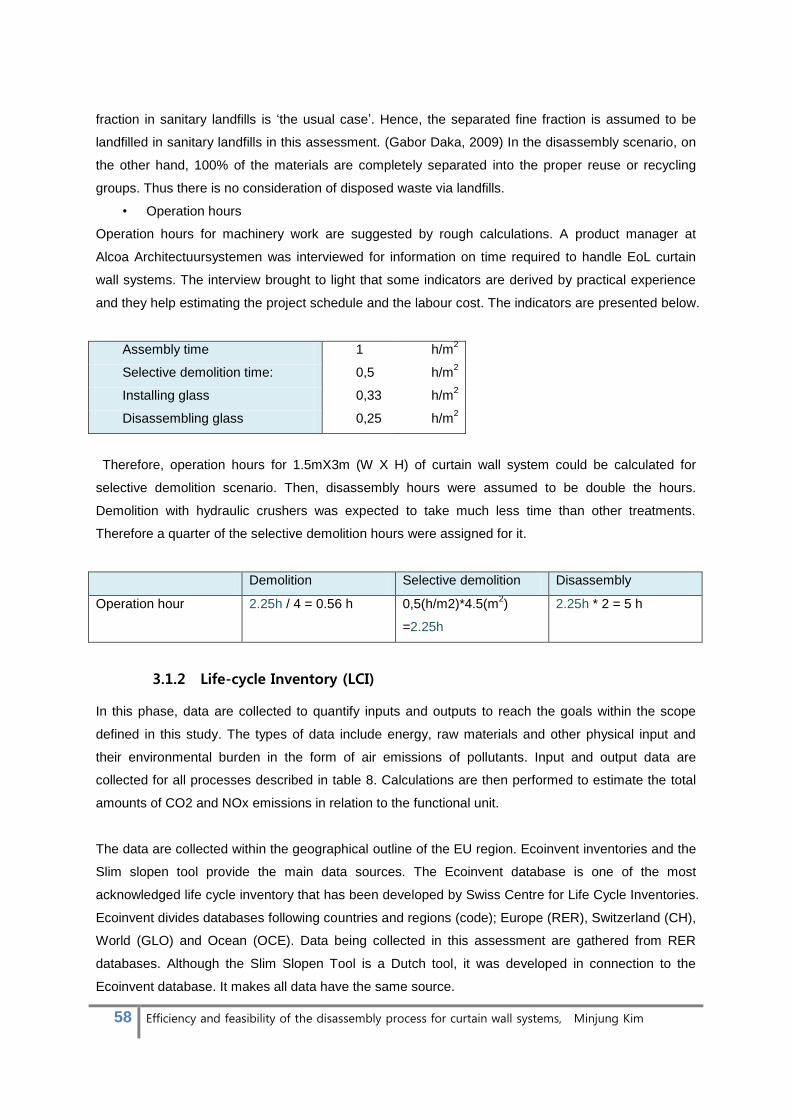
58 Efficiency and feasibility of the disassembly process for curtain wall systems, Minjung Kim
fraction in sanitary landfills is ‘the usual case’. Hence, the separated fine fraction is assumed to be
landfilled in sanitary landfills in this assessment. (Gabor Daka, 2009) In the disassembly scenario, on
the other hand, 100% of the materials are completely separated into the proper reuse or recycling
groups. Thus there is no consideration of disposed waste via landfills.
• Operation hours
Operation hours for machinery work are suggested by rough calculations. A product manager at
Alcoa Architectuursystemen was interviewed for information on time required to handle EoL curtain
wall systems. The interview brought to light that some indicators are derived by practical experience
and they help estimating the project schedule and the labour cost. The indicators are presented below.
Assembly time 1 h/m2
Selective demolition time: 0,5 h/m2
Installing glass 0,33 h/m2
Disassembling glass 0,25 h/m2
Therefore, operation hours for 1.5mX3m (W X H) of curtain wall system could be calculated for
selective demolition scenario. Then, disassembly hours were assumed to be double the hours.
Demolition with hydraulic crushers was expected to take much less time than other treatments.
Therefore a quarter of the selective demolition hours were assigned for it.
Demolition Selective demolition Disassembly
Operation hour 2.25h / 4 = 0.56 h 0,5(h/m2)*4.5(m2)
=2.25h
2.25h * 2 = 5 h
3.1.2 Life-cycle Inventory (LCI)
In this phase, data are collected to quantify inputs and outputs to reach the goals within the scope
defined in this study. The types of data include energy, raw materials and other physical input and
their environmental burden in the form of air emissions of pollutants. Input and output data are
collected for all processes described in table 8. Calculations are then performed to estimate the total
amounts of CO2 and NOx emissions in relation to the functional unit.
The data are collected within the geographical outline of the EU region. Ecoinvent inventories and the
Slim slopen tool provide the main data sources. The Ecoinvent database is one of the most
acknowledged life cycle inventory that has been developed by Swiss Centre for Life Cycle Inventories.
Ecoinvent divides databases following countries and regions (code); Europe (RER), Switzerland (CH),
World (GLO) and Ocean (OCE). Data being collected in this assessment are gathered from RER
databases. Although the Slim Slopen Tool is a Dutch tool, it was developed in connection to the
Ecoinvent database. It makes all data have the same source.
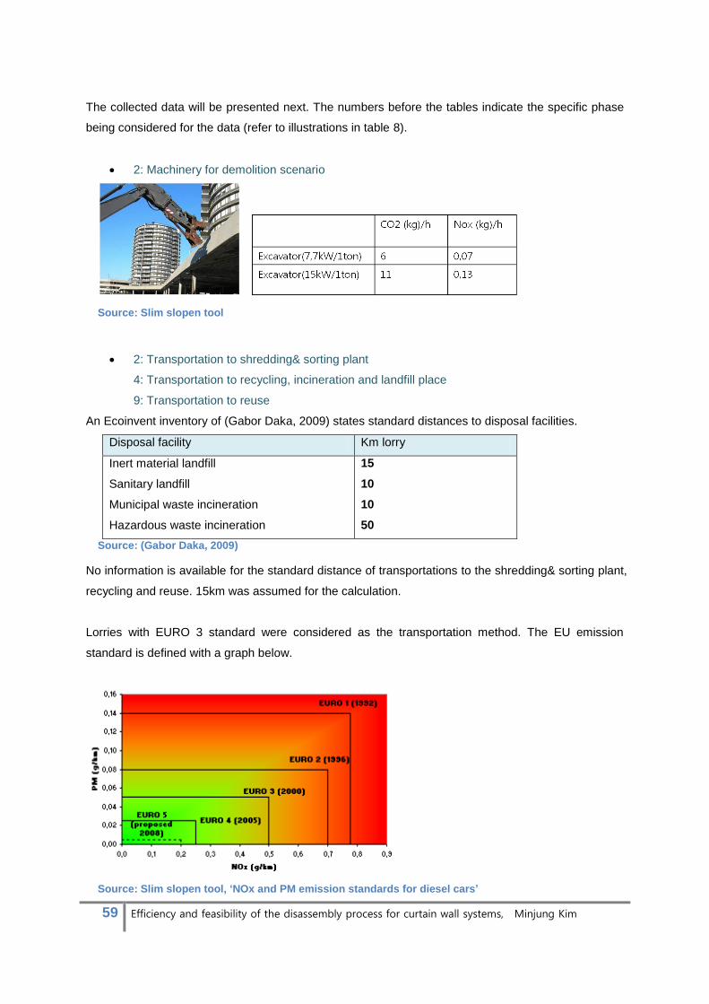
59 Efficiency and feasibility of the disassembly process for curtain wall systems, Minjung Kim
The collected data will be presented next. The numbers before the tables indicate the specific phase
being considered for the data (refer to illustrations in table 8).
2: Machinery for demolition scenario
Source: Slim slopen tool
2: Transportation to shredding& sorting plant
4: Transportation to recycling, incineration and landfill place
9: Transportation to reuse
An Ecoinvent inventory of (Gabor Daka, 2009) states standard distances to disposal facilities.
Disposal facility Km lorry
Inert material landfill
Sanitary landfill
Municipal waste incineration
Hazardous waste incineration
15
10
10
50
Source: (Gabor Daka, 2009)
No information is available for the standard distance of transportations to the shredding& sorting plant,
recycling and reuse. 15km was assumed for the calculation.
Lorries with EURO 3 standard were considered as the transportation method. The EU emission
standard is defined with a graph below.
Source: Slim slopen tool, ‘NOx and PM emission standards for diesel cars’
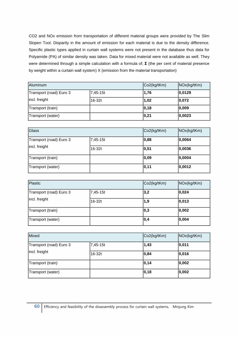
60 Efficiency and feasibility of the disassembly process for curtain wall systems, Minjung Kim
CO2 and NOx emission from transportation of different material groups were provided by The Slim
Slopen Tool. Disparity in the amount of emission for each material is due to the density difference.
Specific plastic types applied in curtain wall systems were not present in the database thus data for
Polyamide (PA) of similar density was taken. Data for mixed material were not available as well. They
were determined through a simple calculation with a formula of; Σ (the per cent of material presence
by weight within a curtain wall system) X (emission from the material transportation)
Aluminum Co2(kg/tKm) NOx(kg/tKm)
Transport (road) Euro 3
incl. freight
7,45-15t 1,76 0,0129
16-32t 1,02 0,072
Transport (train) 0,18 0,009
Transport (water) 0,21 0,0023
Glass Co2(kg/tKm) NOx(kg/tKm)
Transport (road) Euro 3
incl. freight
7,45-15t 0,88 0,0064
16-32t 0,51 0,0036
Transport (train) 0,09 0,0004
Transport (water) 0,11 0,0012
Plastic Co2(kg/tKm) NOx(kg/tKm)
Transport (road) Euro 3
incl. freight
7,45-15t 3,2 0,024
16-32t 1,9 0,013
Transport (train) 0,3 0,002
Transport (water) 0,4 0,004
Mixed Co2(kg/tKm) NOx(kg/tKm)
Transport (road) Euro 3
incl. freight
7,45-15t 1,43 0,011
16-32t 0,84 0,016
Transport (train) 0,14 0,002
Transport (water) 0,18 0,002

61 Efficiency and feasibility of the disassembly process for curtain wall systems, Minjung Kim
5: Aluminium recycling
Ecoinvent inventory of Life cycle inventories of Metal, Part I Aluminium (2009), provides data on
emission arising from extracting and refining primary aluminium. Emission from the recycling process
is not given thus it was estimated with the fact that the recycling process requires 5% of the energy
used in primary production, and emits 5% of the GHGs. (Tyabji & Nelson, 2008)
Co2(kg/T) Nox(Kg/T)
Primary Aluminum 1500 0,0639
Recycling Aluminium 75 0,0032
6: Glass recycling
There was an assumption discussed in the paragraph 3.1.1.4 that all cullet are recycled for
manufacturing of Foam Glass. Ecoinvent inventory of Life cycle inventories of Building products:
Part XIV Insulation Products and Processes (2007) provides data of emission from form glass
production.
CO2(kg/T) NOx(kg/T)
Foam glass production 29.4 1
Source:(Althaus et al., 2007)
7: Energy recovery
Average energy generated from incineration of Refuse-derived fuel(RDF) plastic waste is defined
as 15-17 MJ/kg. CO2 emission from energy generation by means of Natural gas is given by a
report of World Nuclear Association. (WNA, 2011)These data were combined to estimate avoided
CO2 emission from incineration with energy recovery.
CO2(kg/kWh)
Energy generation with Natural Gas 499^e6
Source: (WNA, 2011)
8: Landfill
Ecoinvent inventory of waste treatment services, part V Building material disposal (2009), estimates
total gas production in a sanitary landfill with the building waste. The waste was assumed to have a
general composition of building materials which include concrete, gypsum, steel, glass, etc. The
report observed that sulphur makes up the most volume of the gas emitted from the waste landfills.
The sulphur amount in waste was assumed to be dominated by sulphate from gypsum waste and
other sources are neglected.
Because this research investigates environmental burden from EoL curtain wall systems which do
not include gypsum waste, here it is assumed that landfilled materials show insignificant pollutant
potential.

62 Efficiency and feasibility of the disassembly process for curtain wall systems, Minjung Kim
3.1.3 Life-cycle impact assessment (LCIA)
LCIA assesses the results of the LCI (the quantified inputs and outputs) to understand their
environmental significance.(D.Elcock., 2007) Here the results are represented in the total amount of
CO2 and NOx emission occurring through all processes being considered in the system. Hence the
LCIA produce estimates of the impact in potential of global warming in terms of Kg of CO2 and the
potential of smog resulting from Kgs of NOx.
Computation of the assessment is described for each scenario in the following tables. The amounts of
materials divided to different treatments are given in table 9, 10 and 11 by considering diversion rates
that were assumed in the paragraph 3.1.1.4. Initial set-up for the assessment was a curtain walling
fragment of 1.5mX3m (W X H) of 107.73kg in the total weight (refer to the paragraph 2.2.2.1).
Calculations first are carried out for the 4.5m2
specimen to count details of the material composition
then the outcomes are converted to a unit of m2 because using unusual units can be misleading.
A flow model that shows collections of input and output processes within the boundaries are
schematized for three scenarios [Figure 37, 38 and 39]. (+) and (-) signs on the flow model indicate
whether the process increases or decreases the environmental burden. For example, incineration
activities reduce the final environmental burden by converting the heat energy into electricity.
Mass (kg/4.5m2 ) Recycling (kg) Incineration (kg) Inert landfill (kg)
Aluminium 16.30 14.68 - -
Glass 72.36 57.89 - -
Mixed plastics 19.05 - 15.24
Residue - - - 19.91
table 9 Weight of materials to different treatment in the demolition scenario
Mass (kg/4.5m2 ) Recycling (kg) Incineration (kg) Inert landfill (kg)
Aluminium 16.30 15.50 - -
Glass 72.36 57.89 - -
Mixed plastics 19.05 - 15.24 -
Residue - - - 19.10
table 10 Weight of materials to different treatment in the selective demolition scenario
Mass (kg/4.5m2 ) Reuse (kg) Recycling (kg) Incineration (kg)
Aluminium 16.30 8.16 8.16 -
Glass 72.36 36.18 36.18 -
Mixed plastics 19.05 7.24 - 11.81
Residue - - - 0
table 11 Weight of materials to different treatment in the disassembly scenario

63 Efficiency and feasibility of the disassembly process for curtain wall systems, Minjung Kim
Scenario #1 Demolition
Figure 37 A flow model of the demolition scenario
Machinery CO2 (kg/h)
NOx(kg/h) Operation hour(h) CO2 (kg) NOx(kg)
Excavator(15kW/1ton) 11 0.13 0.56 6.160 0.0728
Transportation CO2 NOx Distance Load
CO2 (kg) NOx(kg) (kg/tkm) (kg/tkm) (km) (kg)
1.43 0.011 15 107.73 2.311 0.0178 Mixed material
(7.45-15t lorry, Euro 3)
Aluminum 1.76 0.0129 15 14.68 0.388 0.0028
Glass 0.88 0.0064 15 57.89 0.764 0.0056
Plastics 3.2 0.024 10 15.24 0.488 0.0037
Residue 1.43 0.011 15 19.91 0.427 0.0033
Treatment CO2 NOx
Weight (kg) CO2 (kg) NOx(kg) (kg/T) (kg/T)
Aluminium recycling 75 0.0032 15.24 1.143 0.0000
Manufacturing Foam Glass
29.4 1 57.89 1.702 0.0579
Energy recovery kWh/T Weight(kg) CO2(kg/kWh) *^e6
CO2 (kg) from Natural Gas fuel
Energy recovery from 4722 15.24 499 -0.036 -
plastic incineration
Total amount of emission / 4.5m2 13.347 0.1638
Total amount of emission/ m2 2.966 0.0364
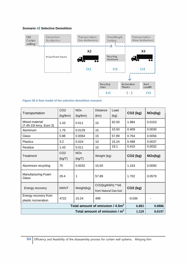
64 Efficiency and feasibility of the disassembly process for curtain wall systems, Minjung Kim
Scenario #2 Selective Demolition
Figure 38 A flow model of the selective demolition scenario
Transportation CO2 NOx Distance Load
CO2 (kg) NOx(kg) (kg/tkm) (kg/tkm) (km) (kg)
1.43 0.011 15 92.50 1.984 0.0153 Mixed material
(7.45-15t lorry, Euro 3)
Aluminum 1.76 0.0129 15 15.50 0.409 0.0030
Glass 0.88 0.0064 15 57.89 0.764 0.0056
Plastics 3.2 0.024 10 15.24 0.488 0.0037
Residue 1.43 0.011 15 19.1 0.410 0.0032
Treatment CO2 NOx
Weight (kg) CO2 (kg) NOx(kg) (kg/T) (kg/T)
Aluminium recycling 75 0.0032 15.50 1.163 0.0000
Manufacturing Foam Glass
29.4 1 57.89 1.702 0.0579
Energy recovery kWh/T Weight(kg) CO2(kg/kWh) *^e6
CO2 (kg) from Natural Gas fuel
Energy recovery from 4722 15.24 499 -0.036 -
plastic incineration
Total amount of emission / 4.5m2 6.883 0.0886
Total amount of emission / m2 1.529 0.0197

65 Efficiency and feasibility of the disassembly process for curtain wall systems, Minjung Kim
Scenario #3 Disassembly
Figure 39 A flow model of the selective demolition scenario
Transportation CO2 NOx Distance Load
CO2 (kg) NOx(kg) (kg/tkm) (kg/tkm) (km) (kg)
Aluminium for reuse 1.76 0.0129 15 8.16 0.215 0.0016
Glazing for reuse 0.88 0.0064 15 43.4 0.573 0.0042
Aluminium for recycling 1.76 0.0129 15 8.16 0.215 0.0016
Glass for recycling 0.88 0.0064 15 43.4 0.573 0.0042
Plastics 3.2 0.024 10 11.8 0.378 0.0028
Glazing rim 3.2 0.024 10 7.24 0.232 0.0017
Treatment CO2 NOx
Weight (kg) CO2 (kg) NOx(kg) (kg/T) (kg/T)
Aluminium recycling 75 0.0032 8.16 0.612 0.0000
Manufacturing Foam Glass
29.4 1 43.4 1.276 0.0434
Energy recovery kWh/T Weight(kg) CO2(kg/kWh) *^e6
CO2 (kg) from Natural Gas fuel
Energy recovery from 4722 11.81 499 -0.028 -
plastic incineration
Total amount of emission / 4.5m2 4.046 0.0595

66 Efficiency and feasibility of the disassembly process for curtain wall systems, Minjung Kim
3.1.4 Life-cycle Interpretation
The LCIA phase focused to combine data from LCI phase and estimated the environmental impact in
regard to the total amount of emission per square meters. Table 12 provides a summary of
conclusions from the competitive assessment.
#1 Demolition #2 Selective demolition #3 Disassembly
CO2(kg)/ m2 2.966 1.529 (-48.45%) 0.899 (-69.97%)
NOx(kg)/ m2 0.0364 0.0197 (-45.88%) 0.0132 (-63.74%)
table 12 conclusion from the competitive assessment with three scenarios
The demolition scenario, not unexpectedly, shows the largest amount of CO2 and NOx emission. The
amount of emissions continuously is declining toward disassembly scenario. Percentages indicated in
red show relative reduction rates compared to the demolition scenario. Selective demolition reduces
CO2 emission by 48% whereas disassembly mitigates it by almost 70%. NOx emissions also are
decreased by the comparable amount to CO2 in both scenarios. The comparison concludes the
environmental impact can be significantly improved by facilitating disassembly.
Cumulative charts of CO2 and NOx emissions in a unit of kg are presented in figure 40. Heights of
columns address the total amount of emissions cumulated throughout the assessment boundary and
blocks in different colours indicate specific phases of EoL scenarios. The charts clearly emphasize
significant reductions of CO2 and NOx emissions in the disassembly scenario. Compositions of
columns are compared to distinguish which phase has a critical influence on the reduction. On both
charts of CO2 and NOx emissions, blue and red blocks were eliminated in disassembly scenario and
purple block is decreased a significant amount. It concludes three critical factors of the reduction;
1) Avoidance of machinery operations (blue)
2) Avoidance of transportation to shredding plants (red) and
3) Avoidance of recycling process by diverting components to reuse
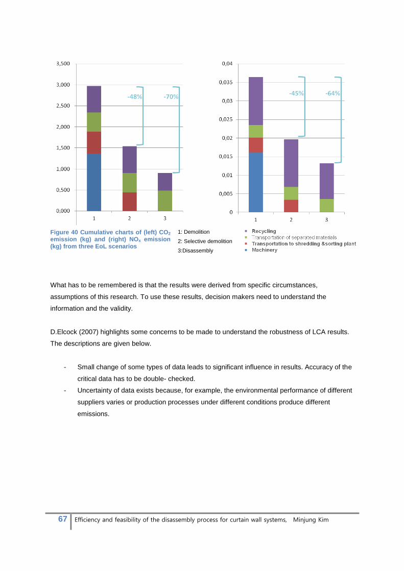
67 Efficiency and feasibility of the disassembly process for curtain wall systems, Minjung Kim
Figure 40 Cumulative charts of (left) CO2 emission (kg) and (right) NOx emission (kg) from three EoL scenarios
1: Demolition
2: Selective demolition
3:Disassembly
What has to be remembered is that the results were derived from specific circumstances,
assumptions of this research. To use these results, decision makers need to understand the
information and the validity.
D.Elcock (2007) highlights some concerns to be made to understand the robustness of LCA results.
The descriptions are given below.
- Small change of some types of data leads to significant influence in results. Accuracy of the
critical data has to be double- checked.
- Uncertainty of data exists because, for example, the environmental performance of different
suppliers varies or production processes under different conditions produce different
emissions.
68 Efficiency and feasibility of the disassembly process for curtain wall systems, Minjung Kim
3.1.5 Conclusion of environmental assessment
Principles of life-cycle-assessment were integrated to estimate feasibility of disassembly
implementation for curtain wall systems in regards to the environmental impact. Demolition and
selective demolition scenarios were assessed along with disassembly scenario to provide standards
of the feasibility. A systematic process of LCA that follows the ISO standards was tailored to the
specific life cycle of “grave-gate” of curtain wall systems to estimate the end-of–life scenarios. Instead
of analyzing a variety of impacts on the environment, the assessment focused to provide single
indicators as a simple decision making approach. The total kg of CO2 and NOx emission presented
results of environmental burdens from the three scenarios. The assessment concluded that the
environmental impact can be significantly reduced by facilitating disassembly instead of demolition
and selective demolition which are currently commonly practiced. For successful applications, reuse
should be encouraged because diverting materials to reuse was measured as one of major
contributors of significant reduction of the environmental burden.

69 Efficiency and feasibility of the disassembly process for curtain wall systems, Minjung Kim
3.2 Economic assessment
Economic impacts of implementing demolition, selective demolition and disassembly are accessed
with their net cost which indicates the total cost offset by revenue from material salvage. The
assessment takes account of all items generating costs or revenue throughout the life cycle of curtain
wall systems within the analysis boundary.
A Universal equation is introduced to reduce complexity from variability of geographical conditions.
The equation was developed following a similar method described by Symonds in association
ARGUS, COWI and PRC Bouwcentrum in 1999. An economic model in their research was produced
for a quantified assessment of the costs of demolition versus deconstruction operations. It is thus
revised for the purpose of estimating economic impacts of three scenarios being considered in this
research. The universal equation is constructed in the form of several separated phases which help
users to get a better understanding of which factors are causing critical impacts on the resultant cost.
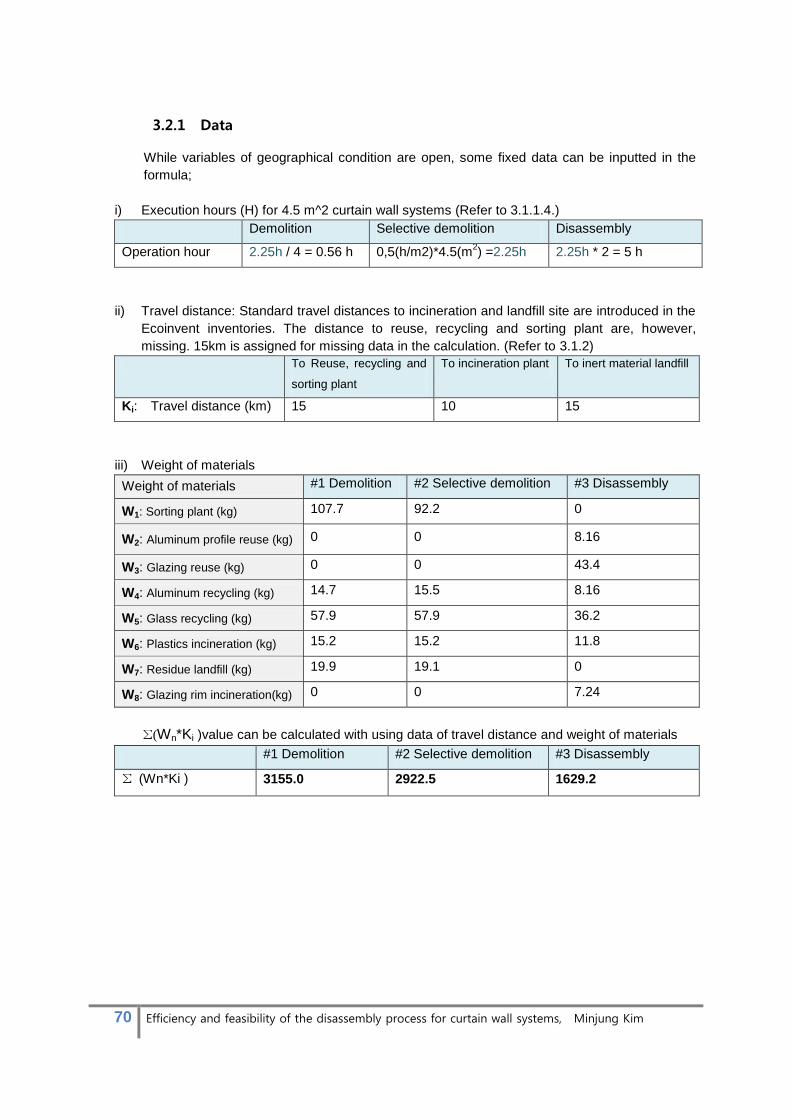
70 Efficiency and feasibility of the disassembly process for curtain wall systems, Minjung Kim
3.2.1 Data
While variables of geographical condition are open, some fixed data can be inputted in the
formula;
i) Execution hours (H) for 4.5 m^2 curtain wall systems (Refer to 3.1.1.4.)
Demolition Selective demolition Disassembly
Operation hour 2.25h / 4 = 0.56 h 0,5(h/m2)*4.5(m2) =2.25h 2.25h * 2 = 5 h
ii) Travel distance: Standard travel distances to incineration and landfill site are introduced in the
Ecoinvent inventories. The distance to reuse, recycling and sorting plant are, however,
missing. 15km is assigned for missing data in the calculation. (Refer to 3.1.2)
To Reuse, recycling and
sorting plant
To incineration plant To inert material landfill
Ki: Travel distance (km) 15 10 15
iii) Weight of materials
Weight of materials #1 Demolition #2 Selective demolition #3 Disassembly
W1: Sorting plant (kg) 107.7 92.2 0
W2: Aluminum profile reuse (kg) 0 0 8.16
W3: Glazing reuse (kg) 0 0 43.4
W4: Aluminum recycling (kg) 14.7 15.5 8.16
W5: Glass recycling (kg) 57.9 57.9 36.2
W6: Plastics incineration (kg) 15.2 15.2 11.8
W7: Residue landfill (kg) 19.9 19.1 0
W8: Glazing rim incineration(kg) 0 0 7.24
Σ(Wn*Ki )value can be calculated with using data of travel distance and weight of materials
#1 Demolition #2 Selective demolition #3 Disassembly
Σ (Wn*Ki ) 3155.0 2922.5 1629.2

71 Efficiency and feasibility of the disassembly process for curtain wall systems, Minjung Kim
3.2.2 Analysis
The fixed figures are inserted into the equation. The three equations were created for the number of
scenarios. Functions of cost and revenue, on table 39, are separated according to characteristics of
the processes. The sum of the functions in a same row, wherein revenue should be counted as
negative value, would result in the net cost of each scenario. As shown on the table, functions aligned
in a column are derived from the same activities thus contain identical unknown variables. The
functions with the same unknown variables then can be compared to determine which scenario costs
more in which phase of processing and in what quantity. For example, a result of subtraction of the
two equations for net cost of disassembly scenario and selective demolition scenarios, shows
negative values for most of activities. This means that disassembly scenario costs less than the
selective demolition scenario for these activities.
[The Net Costs of Disassembly - The Net Costs of Selective Demolition]
= 2.25L +(E- E2) – (92.2S + 1293.3T + 7.34Palu+ 21.7Pgl+3.4Ppla+ 19.1Dre )
The relationship is inalterable because it excludes variability of different project conditions.
Figure 41 Functions of cost and revenue from three scenarios are separated according to the category of processing phases. The functions aligned in a column can be compared because they have same unknown variables. The sum in a row results in the net costs for each scenarios
Net costs of the three scenarios are compared in the same way. The comparison results the third
scenario, disassembly, providing economic benefits in sorting, transportation and recycling/disposal
phases. Functions of machinery cost and revenue from material/energy recovery could not be
compared by the same means due to intervention of some additional unknowns. The relationships
thus are assumed to be based on knowledge of the processes. A relationship of machinery expense
is predicted to be E1 > E2 > E because demolition and selective demolition demand more extensive
and better machineries than disassembly. Disassembly scenario, in addition, recovers the maximum
amount of materials and energy. The consequent revenue from material and energy recovery is likely
to exceed that from other scenarios. The condition for this to be true is that there would have to be a
better functioning market for used aluminium profiles and glazing units.
72 Efficiency and feasibility of the disassembly process for curtain wall systems, Minjung Kim
3.2.3 Conclusion of Economic assessment
In this section, economic assessments were carried out to determine economic feasibility of
disassembly scenario at the end-of-life of curtain wall systems. Two conventional EoL scenarios,
demolition and selective demolition, were estimated at the same time to suggest standards of the
feasibility. A universal equation was designed to derive net cost of the three scenarios. The equations
are structured in clear categories of activities that allow indentifying which phase of processing
provide economic advantages or disadvantages.
The assessment was analyzed and it was concluded that disassembly implementation not only
maximizes revenue from material and energy recovery but also reduces expenses of most phases of
the processing. Increased cost of labour was the only downside of the disassembly scenario in regard
to the life cycle cost.
The economic feasibility of disassembly would be realized when two conditions are improved;
i) The execution hours are minimized and thus the disassembly labour expense;
ii) A trade system for secondary curtain wall components is provided to enhance the market and
guarantee the profit from component’s recovery and committing disassembly.

73 Efficiency and feasibility of the disassembly process for curtain wall systems, Minjung Kim
4. Design
4.1 Design strategies
Design challenges to realize feasible disassembly implementation were arose during the early phase
of this research. While environmental assessment proved that disassembly scenario can mitigate the
environmental load in a significant amount, there were two aspects to be improved to enhance
economic feasibility of disassembly (Refer to 3.2.3). The aspects should be evenly investigated to
realize feasible disassembly. Here design discussion, however, is limited to a possible extent of
solutions which can be realized via product design. Hence design strategies are suggested mainly to
reduce the disassembly hours of curtain wall systems. The strategies stem from possible solutions of
the problems found in the job site activities and material flow. (Refer to paragraph 2.3.3)
STRATEGIES
Minimize the disassembly hours of curtain wall systems
Reduce disassembly tasks - Build the system with easy connections
- Build the system in reversible orders
- Ensure connections & fasteners are easily accessible
Reduce production support
tasks
- Remove a need of temporary glazing fix
- Remove a need of erecting exterior workstation
Table 13 Design challenges and strategies
The strategies will be taken into account in the beginning of product design to improve disassembly
of curtain wall systems. Societies and governments, however, need to work alongside the product
designers to encourage the constant improvement. Strategies to drive voluntary actions of industry
members or governmental actions to force the transition would be necessary to solve complex
problems arising from implementing disassembly for curtain wall systems. These issues, however, are
beyond the scope of product design. Hence they will be separately discussed in section 5.
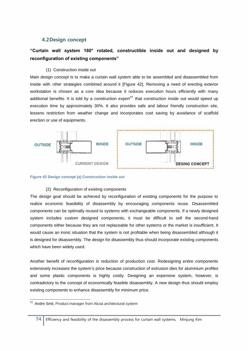
74 Efficiency and feasibility of the disassembly process for curtain wall systems, Minjung Kim
4.2 Design concept
“Curtain wall system 180° rotated, constructible inside out and designed by
reconfiguration of existing components”
(1) Construction inside out
Main design concept is to make a curtain wall system able to be assembled and disassembled from
inside with other strategies combined around it [Figure 42]. Removing a need of erecting exterior
workstation is chosen as a core idea because it reduces execution hours efficiently with many
additional benefits. It is told by a construction expert††
that construction inside out would speed up
execution time by approximately 30%. It also provides safe and labour friendly construction site,
lessens restriction from weather change and incorporates cost saving by avoidance of scaffold
erection or use of equipments.
Figure 42 Design concept (a) Construction inside out
(2) Reconfiguration of existing components
The design goal should be achieved by reconfiguration of existing components for the purpose to
realize economic feasibility of disassembly by encouraging components reuse. Disassembled
components can be optimally reused to systems with exchangeable components. If a newly designed
system includes custom designed components, it must be difficult to sell the second-hand
components either because they are not replaceable for other systems or the market is insufficient. It
would cause an ironic situation that the system is not profitable when being disassembled although it
is designed for disassembly. The design for disassembly thus should incorporate existing components
which have been widely used.
Another benefit of reconfiguration is reduction of production cost. Redesigning entire components
extensively increases the system’s price because construction of extrusion dies for aluminium profiles
and some plastic components is highly costly. Designing an expensive system, however, is
contradictory to the concept of economically feasible disassembly. A new design thus should employ
existing components to enhance disassembly for minimum price.
††
Andre Smit, Product manager from Alcoa architectural system
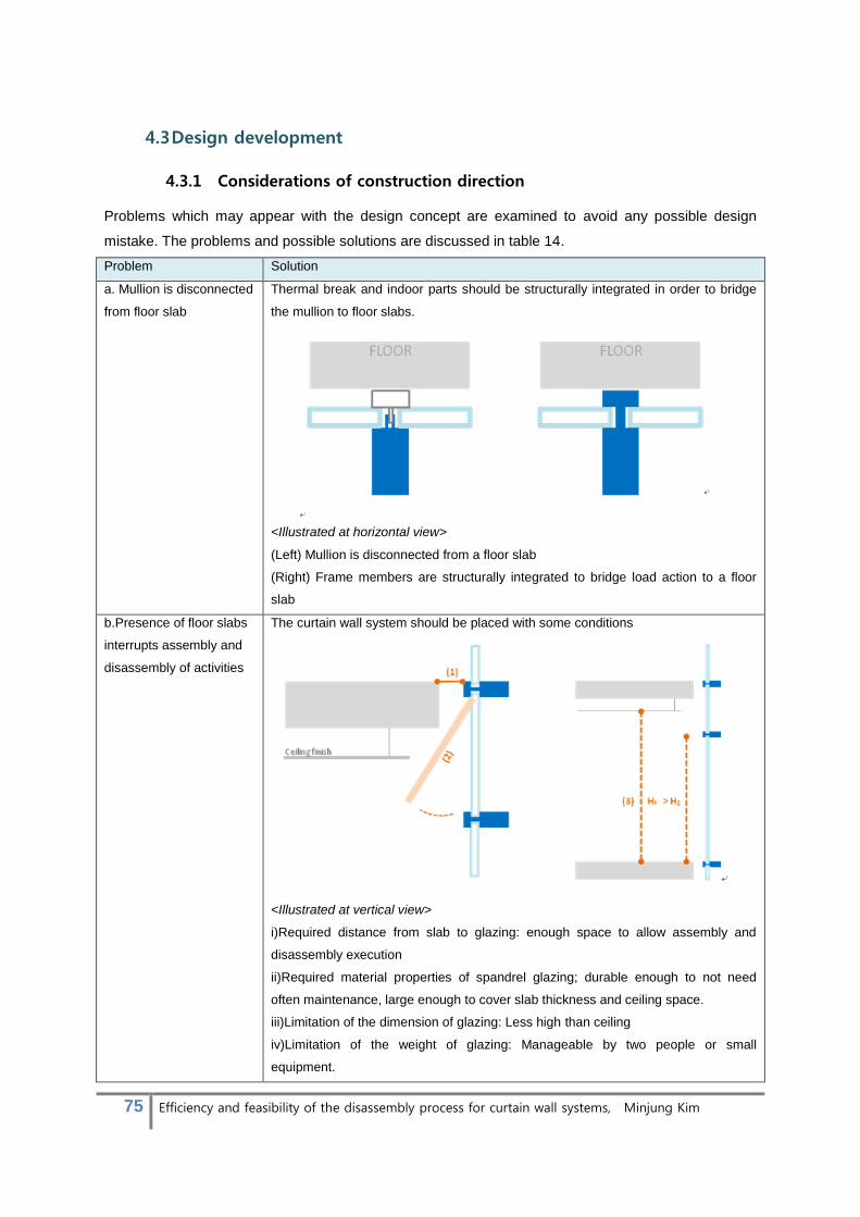
75 Efficiency and feasibility of the disassembly process for curtain wall systems, Minjung Kim
4.3 Design development
4.3.1 Considerations of construction direction
Problems which may appear with the design concept are examined to avoid any possible design
mistake. The problems and possible solutions are discussed in table 14.
Problem Solution
a. Mullion is disconnected
from floor slab
Thermal break and indoor parts should be structurally integrated in order to bridge
the mullion to floor slabs.
<Illustrated at horizontal view>
(Left) Mullion is disconnected from a floor slab
(Right) Frame members are structurally integrated to bridge load action to a floor
slab
b.Presence of floor slabs
interrupts assembly and
disassembly of activities
The curtain wall system should be placed with some conditions
<Illustrated at vertical view>
i)Required distance from slab to glazing: enough space to allow assembly and
disassembly execution
ii)Required material properties of spandrel glazing; durable enough to not need
often maintenance, large enough to cover slab thickness and ceiling space.
iii)Limitation of the dimension of glazing: Less high than ceiling
iv)Limitation of the weight of glazing: Manageable by two people or small
equipment.
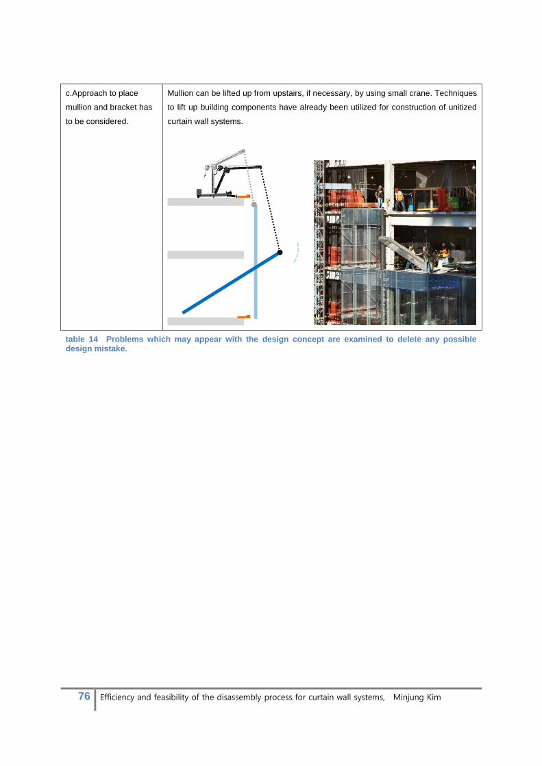
76 Efficiency and feasibility of the disassembly process for curtain wall systems, Minjung Kim
c.Approach to place
mullion and bracket has
to be considered.
Mullion can be lifted up from upstairs, if necessary, by using small crane. Techniques
to lift up building components have already been utilized for construction of unitized
curtain wall systems.
table 14 Problems which may appear with the design concept are examined to delete any possible design mistake.
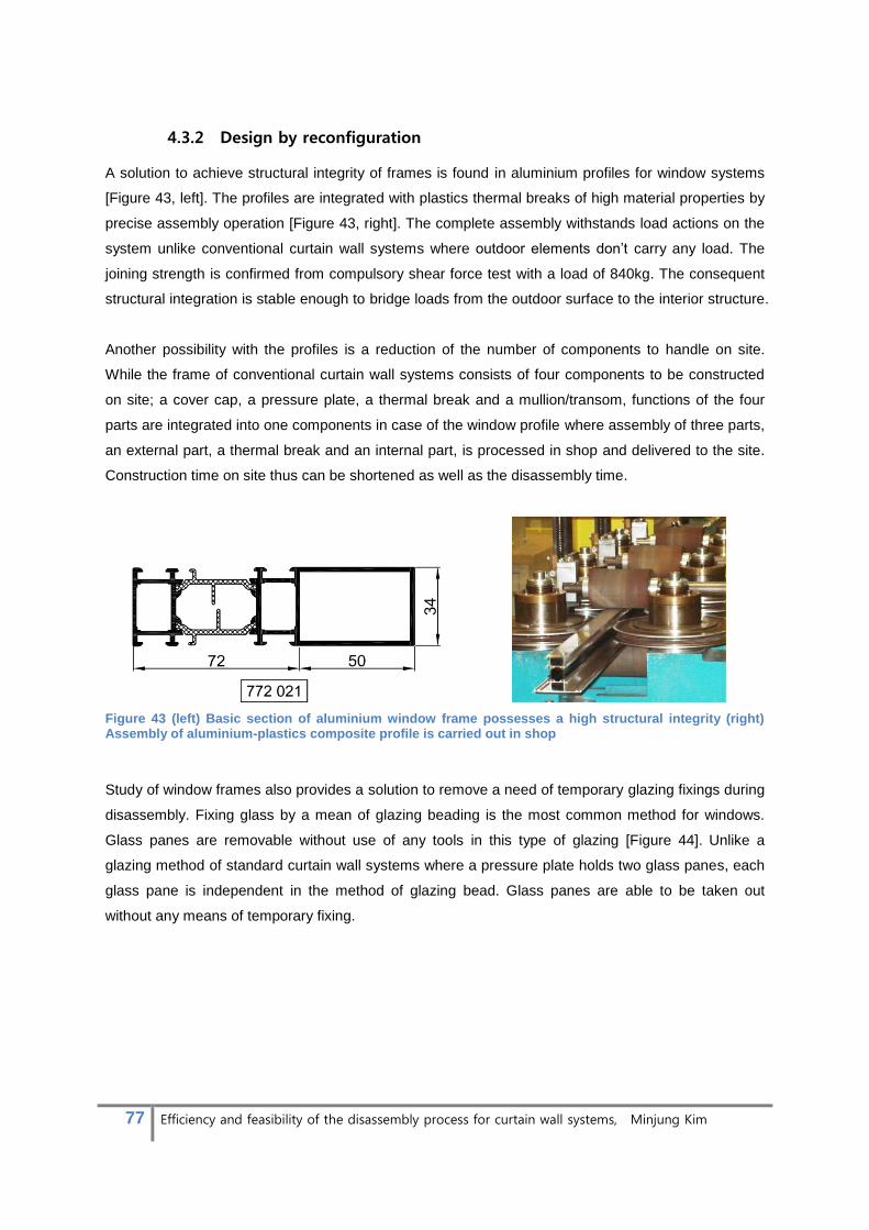
77 Efficiency and feasibility of the disassembly process for curtain wall systems, Minjung Kim
4.3.2 Design by reconfiguration
A solution to achieve structural integrity of frames is found in aluminium profiles for window systems
[Figure 43, left]. The profiles are integrated with plastics thermal breaks of high material properties by
precise assembly operation [Figure 43, right]. The complete assembly withstands load actions on the
system unlike conventional curtain wall systems where outdoor elements don’t carry any load. The
joining strength is confirmed from compulsory shear force test with a load of 840kg. The consequent
structural integration is stable enough to bridge loads from the outdoor surface to the interior structure.
Another possibility with the profiles is a reduction of the number of components to handle on site.
While the frame of conventional curtain wall systems consists of four components to be constructed
on site; a cover cap, a pressure plate, a thermal break and a mullion/transom, functions of the four
parts are integrated into one components in case of the window profile where assembly of three parts,
an external part, a thermal break and an internal part, is processed in shop and delivered to the site.
Construction time on site thus can be shortened as well as the disassembly time.
Figure 43 (left) Basic section of aluminium window frame possesses a high structural integrity (right) Assembly of aluminium-plastics composite profile is carried out in shop
Study of window frames also provides a solution to remove a need of temporary glazing fixings during
disassembly. Fixing glass by a mean of glazing beading is the most common method for windows.
Glass panes are removable without use of any tools in this type of glazing [Figure 44]. Unlike a
glazing method of standard curtain wall systems where a pressure plate holds two glass panes, each
glass pane is independent in the method of glazing bead. Glass panes are able to be taken out
without any means of temporary fixing.
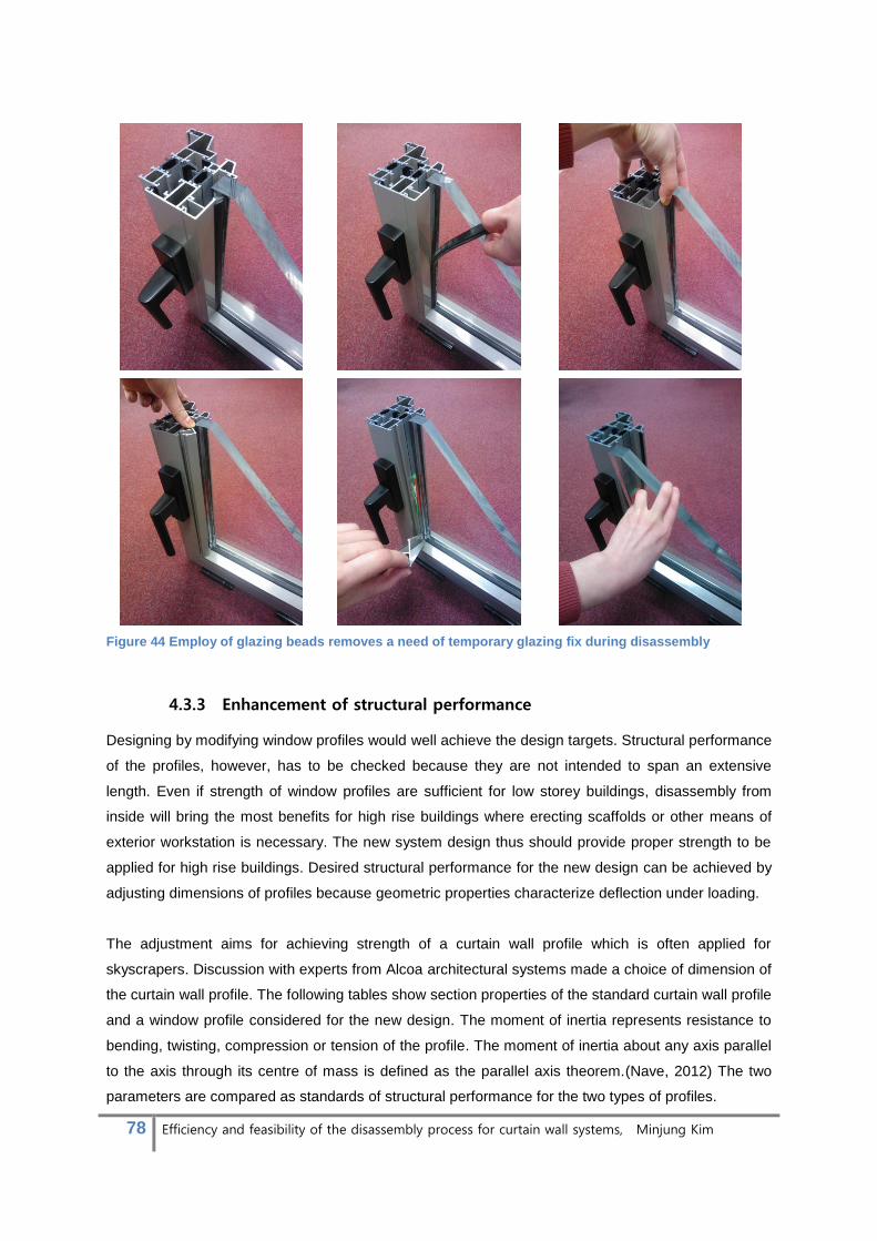
78 Efficiency and feasibility of the disassembly process for curtain wall systems, Minjung Kim
Figure 44 Employ of glazing beads removes a need of temporary glazing fix during disassembly
4.3.3 Enhancement of structural performance
Designing by modifying window profiles would well achieve the design targets. Structural performance
of the profiles, however, has to be checked because they are not intended to span an extensive
length. Even if strength of window profiles are sufficient for low storey buildings, disassembly from
inside will bring the most benefits for high rise buildings where erecting scaffolds or other means of
exterior workstation is necessary. The new system design thus should provide proper strength to be
applied for high rise buildings. Desired structural performance for the new design can be achieved by
adjusting dimensions of profiles because geometric properties characterize deflection under loading.
The adjustment aims for achieving strength of a curtain wall profile which is often applied for
skyscrapers. Discussion with experts from Alcoa architectural systems made a choice of dimension of
the curtain wall profile. The following tables show section properties of the standard curtain wall profile
and a window profile considered for the new design. The moment of inertia represents resistance to
bending, twisting, compression or tension of the profile. The moment of inertia about any axis parallel
to the axis through its centre of mass is defined as the parallel axis theorem.(Nave, 2012) The two
parameters are compared as standards of structural performance for the two types of profiles.

79 Efficiency and feasibility of the disassembly process for curtain wall systems, Minjung Kim
Ix = 312.8 cm4
Iy = 44.5 cm4
Wx = 37.7 cm3
Wy = 17.8 cm3
Ix = 125.8 cm4
Iy = 17.2 cm4
Wx = 18.4 cm3
Wy = 4.4 cm3
Where,
Ix: The moment of inertia of the section about the x-axis
Iy: The moment of inertia of the section about the y-axis
Wx: The parallel axis theorem for mass moment of inertia
about the x-axis
Wy: The parallel axis theorem for mass moment of inertia
about the y-axis
Table 15 Structural characteristics of a standard curtain wall profile(up) and a window profile considered in the new design(down)
Table 15 addresses that the moment of inertia and the parallel axis theorem of the curtain wall profile
are more than twice that of the window profile. The window profile was thus enlarged to surpass the
values. The following table demonstrates section properties of the window profile after adjustment
which became competitive to the curtain wall profile.
Ix = 371.24 cm4
Iy = 48.73 cm4
Wx = 36.87 cm3
Wy = 10.38 cm3
Table 16 Overall section properties of the window profile after dimension adjustment; Sectional area of thermal break was excluded from the calculation because it possesses different material characteristics.

80 Efficiency and feasibility of the disassembly process for curtain wall systems, Minjung Kim
Adjusted dimension of frames, however, causes another problem from an aesthetic point of view that
an exterior dimension of the modified frame is almost twice that of the curtain wall system. The
dimension has to be reduced to appeal to customers who tend to pursue minimal appearance of
structures. The following chapter will focus on the solution.
4.3.4 Minimizing structural appearance
Challenge
This chapter concentrates to achieve minimum appearance of profiles in the possible range of
requirements for the structural function.
There are technical issues which limit size of the profile. Distance of the glazing flange (A) and the
middle body (B) are controlled by guidelines described below [Figure 45].
i. Distance A should be 17mm at least to secure
glazing units and conceal the rims which require
11.5mm width for adhesive between two glazing
panes. Minimum tolerance of 5.5mm should be
provided to control errors in measurements
which might happen during construction or
manufacturing.
ii. Distance B should be the same width with the
internal part (D) to achieve integration of
counteracting forces which enhance the
structural performance.
Figure 45 Requirements for the distance of glazing flange (A) and middle body (B)
Solution
With the necessary conditions in mind, distance A was reduced from 22mm to 17mm and distance B
was minimized by increasing sectional area of the profile. For the principle of sectional properties,
when the increase in sectional area takes place furthest from the centre of the mass of the profile, the
desired structural performance of the profile can be sustained while reducing the exterior dimension of
the width of the profile. Therefore, the thickness of the profile on the innermost flange (the part on the
right in the diagram above) was changed from 1.7mm to 3.8mm and extra layer was added on the
external side with a cavity of 8mm. The exterior channel was intended to provide another function as
drainage and paragraph 4.3.6 will describe the development. In addition, the reasons why some
notches in rebate area were removed from the section will be discussed in 4.3.5.
The considerations result in the profile illustrated in table 17. The resultant profile demonstrates
slender appearance with an external face width of 5.9cm. The internal dimensions of the basic depth

81 Efficiency and feasibility of the disassembly process for curtain wall systems, Minjung Kim
(C) and the internal side width (D) are smaller than the curtain wall profile of comparative section
properties. It was minimized within the utmost limit of desired section properties to the x-axis which
plays a significant role to withstand wind load. On the other hand, the properties to the y-axis were
reduced to one third. The modification was viable because Iy and Wy values only determine
resistance to gravity which is mainly related to glazing weight. Weight of glazing units and the
required Iy and Wy were calculated to design the profile.
Ix = 370.28 cm4
Iy = 15.12 cm4
Wx = 37.20 cm3
Wy = 5.13 cm3
Table 17 Section properties of the new profile
Table 18 presents details of the calculation processes. The calculation was carried out with a double
glazing unit in the size of 1.8m X 3.3m (Width X Height) and 4mm of a typical thickness of glass
panes. The width of 1.8m is a typical dimension following Dutch floor plans. The height of 3.3m is
assumed to be sufficient to cover a floor height. The load configuration is two point loads on a beam
supported by two simple supports. The two point loads are applied on glazing support components
which are placed in a distance of ‘c’ from the supports (indicated by table 18). It is known that the
smaller the distance is the less the value of Iy and Wy will be. The value, however, is limited by
100mm at the minimum and c <1/10 is only possible in consultation with the supplier of the glazing
unit.
The calculation results in smaller requirements for Iy and Wy values than the new profile can offer. It
verifies that the new profile is strong enough to support the size of glass units.

82 Efficiency and feasibility of the disassembly process for curtain wall systems, Minjung Kim
c <1/10 is only possible in
consultation with the
supplier of the glazing unit.
window height 3300mm Surface area of a glass pane 5,95 m2
Interior pane thickness 4mm Glass weight/m2
20,00 kg/m2
exterior pane thickness 4mm The total glass weight 118,8kg= 1188,0N
Point load 594,0 N
Allowable deflection 3,0 mm
Ealu 70.000 N/mm2
σalu 160 N/mm
2
The moment of inertia
Iy =
*(3*lt2 - 4*c2 )= 11,40 cm4
The parallel axis theorem
Mmax = F*c*1,5 = 89.100 Nmm
Wy =
= 0,56 cm3
Table 18 Calculation details to determine requirements of section properties to support glass weight
In conclusion, dimensions of the profile chosen for the new curtain wall design were challenged to be
reduced in this section to solve problems stated in section 4.3.3. Present requirements to achieve
desired structural performance set the limit of minimum dimensions. The adjustment results in a
profile with 5.9cm external face width. Although there is 0.9cm increase from the width of standard
curtain wall profiles, the extent would appeal for architects when it is considered that standard window
profiles have 7.8cm of external width. Decreased internal dimensions of the profiles bring benefits in
the interior appearance with the new design.

83 Efficiency and feasibility of the disassembly process for curtain wall systems, Minjung Kim
4.3.5 Detail of T-junction
Challenge
A standard detail can be applied for T-junctions of both the curtain wall system and the window
system which features simple butt jointed mullions and transoms [Figure 46]. The standard detail has
spigots which are attached to the adjacent mullion. They engage with hollow sections of transoms so
as to allow slight movement between the transom and the mullion.
Sections of the two systems, however, show a difference in composition of dry zone and wet zone as
illustrated by Figure 47. Wet zone in the section of curtain wall systems is separated from structural
junction of mullions and transoms which makes it rather easy to achieve total elimination of water
penetration. On the other hand, the T- junction of window systems requires particular attention to the
water tightness because it intersects with the wet zone, interrupting the complete sealing between the
gaps in the junction.
Figure 46 Standard detail for T-junctions of the window system(left) and the curtain wall system(right)
Figure 47 Standard sectional composition of dry zone and wet zone for window systems (left) and curtain wall systems (right)

84 Efficiency and feasibility of the disassembly process for curtain wall systems, Minjung Kim
The difference in the sectional configuration results in mastic sealant appearing as a general
solution to ensure watertightness for window systems [Figure48]. Sealing with glue, however, cannot
be a proper option for the new system design because;
1) The permanent connection opposes to design for disassembly.
2) To achieve high effectiveness, mastic sealant shall be finished in factory. It is not appropriate to
use for on-site construction.
3) Lastly, when it is applied to high-rise buildings for maximum benefits of the new design concept,
there are great chances of water leakage on the junction because air flow becomes more
dynamic and strong by being deflected across the high surface.
These facts make the current detail of window profiles unsuitable for the new design and require
new strategies for the watertightness.
Figure 48 Mastic sealant is generally applied to ensure watertightness for window systems.
Solution
Principal idea of new strategies for watertightness is replacing use of mastics to dry gaskets. Dry
gaskets perform better to block water ingress when it is applied to a flat surface which increases
absorption. Notches present in the section of window frames, however, interrupt the application
because it complicates the geometry of gaskets. [Figure 49]. The notches thus should be eliminated if
possible. The notches have functions of (A) fixing window beads and (B) holding gaskets for openable
windows. Figure 50 and 51 exemplify the roles of the notches. When the window profiles are modified
for curtain walling, however, the function B is not required anymore so that two notches can be
removed to simplify the surface geometry. Then the gasket is formed into a simple L-shape with an
extended part to place before glazing bead [Figure 52]. The gasket is grooved to carry water outside.
Mastic sealant

85 Efficiency and feasibility of the disassembly process for curtain wall systems, Minjung Kim
Figure 49 (left) Complicated section of profile interrupts water-tightness when dry-sealing is applied.
Figure 50 (right) Function of notches: (A) fixing window beading
Figure 51 Function of notches (B) holding gaskets for openable windows
Figure 52 modified T-junction detail for new design, the section of profile was simplified by removing unnecessary notches (left) and The resultant geometry of gasket is a simple L-shape (right).
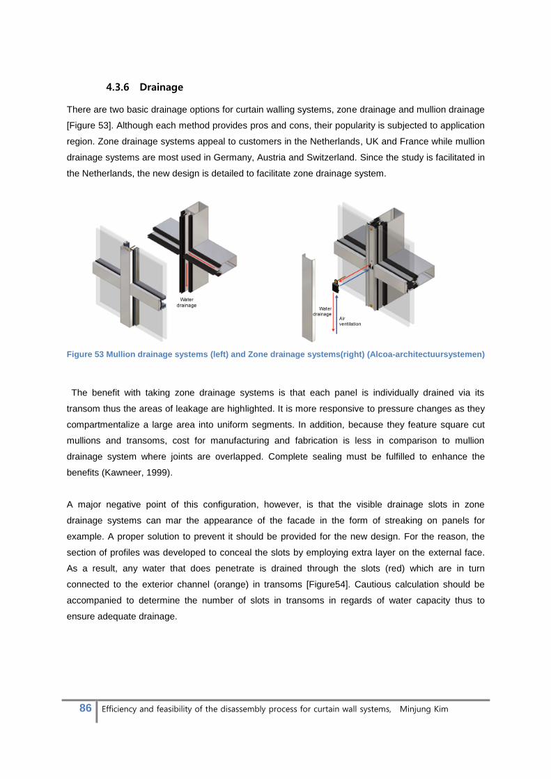
86 Efficiency and feasibility of the disassembly process for curtain wall systems, Minjung Kim
4.3.6 Drainage
There are two basic drainage options for curtain walling systems, zone drainage and mullion drainage
[Figure 53]. Although each method provides pros and cons, their popularity is subjected to application
region. Zone drainage systems appeal to customers in the Netherlands, UK and France while mullion
drainage systems are most used in Germany, Austria and Switzerland. Since the study is facilitated in
the Netherlands, the new design is detailed to facilitate zone drainage system.
Figure 53 Mullion drainage systems (left) and Zone drainage systems(right) (Alcoa-architectuursystemen)
The benefit with taking zone drainage systems is that each panel is individually drained via its
transom thus the areas of leakage are highlighted. It is more responsive to pressure changes as they
compartmentalize a large area into uniform segments. In addition, because they feature square cut
mullions and transoms, cost for manufacturing and fabrication is less in comparison to mullion
drainage system where joints are overlapped. Complete sealing must be fulfilled to enhance the
benefits (Kawneer, 1999).
A major negative point of this configuration, however, is that the visible drainage slots in zone
drainage systems can mar the appearance of the facade in the form of streaking on panels for
example. A proper solution to prevent it should be provided for the new design. For the reason, the
section of profiles was developed to conceal the slots by employing extra layer on the external face.
As a result, any water that does penetrate is drained through the slots (red) which are in turn
connected to the exterior channel (orange) in transoms [Figure54]. Cautious calculation should be
accompanied to determine the number of slots in transoms in regards of water capacity thus to
ensure adequate drainage.

87 Efficiency and feasibility of the disassembly process for curtain wall systems, Minjung Kim
Figure 54 Any water that does penetrate is drained back to the outside through slots (red) which are connected to the exterior channel(orange).
4.4 Design results
The design goal of “Curtain wall system 180° rotated, constructible inside out and designed by
reconfiguration of existing components” was achieved in form of modification of aluminium window
system. Employing aluminium window profiles for new curtain wall design gave rise to several
challenges in enhancement of structural performance, minimizing structural appearance, detailing T-
junction and drainage. The solutions are derived through the design development phase described in
section 4.3 and integrated to the final design.
Section 4.4.1 will deliver drawings of the new design and examples of the application. For the
presentation of application examples, the profile discussed in section 4.3.4 was taken to demonstrate
slender appearance of the facade while offering sufficient resistance against deflection by extensive
wind actions. It was because benefits of the design concept will be most emphasised for the
applications to high rise buildings which demand expensive and time-consuming tasks to build
external work stations.
Section 4.4.2 will focus to demonstrate disassembly efficiency of the new design in comparison to the
standard curtain wall system. The demonstration is carried out with T-connections of new and
standard system. 3D drawings, pictures and a disassembly graph are used to illustrate the
disassembly steps. The method of disassembly graph was learned from a study of Lambert, 1997 for
“Optimal disassembly of complex products”.

88 Efficiency and feasibility of the disassembly process for curtain wall systems, Minjung Kim
Lastly, design results in a new type of curtain wall systems wherein window systems are applied in
construction methods of stick systems. The combination formulates compromised benefits of the two
types of curtain wall systems. Section 4.4.3 will elaborate the advantages of the new design.
4.4.1 Drawings
Design features that characterize benefits of new
design are addressed with following drawings.
Numbers before the drawings indicate the locations on
the facade on a next map.
① Mullions section, horizontal
② Transom section, vertical
③ Mullion to wall connection, horizontal
④ Ground connection, vertical
⑤ Spandrel connection, vertical
(5’): Spandrel connection without floor covering

89 Efficiency and feasibility of the disassembly process for curtain wall systems, Minjung Kim
Figure 55 Mullions detail, horizontal section
[1] A gasket is filling a gap between an insulated glazing unit(IGU) and a glazing bead. It functions to make a water and air tight chamber inside frames. The gasket is dry and removable easily. [2] An IGU is held by glazing beads. This inside glazing system provides a simple and swift method to install and disassemble IGUs. The bead can be clicked in or out to transoms or mullions by stripping out gaskets. [3] Internal and external aluminium profiles and thermal break plastics are integrated into a composite section. The three components are assembled in a shop so as to ensure the quality. As the integration reduces the number of parts to be handled on site, installation/disassembly time is decreased. Section of the profile was designed to promise sufficient section properties t for applications of high rise buildings. To achieve the purpose, the external face width became 1cm wider than standard curtain wall profiles. The internal dimensions, however, provide more slender appearance than curtain wall profiles with similar strength.
2
1
1
3
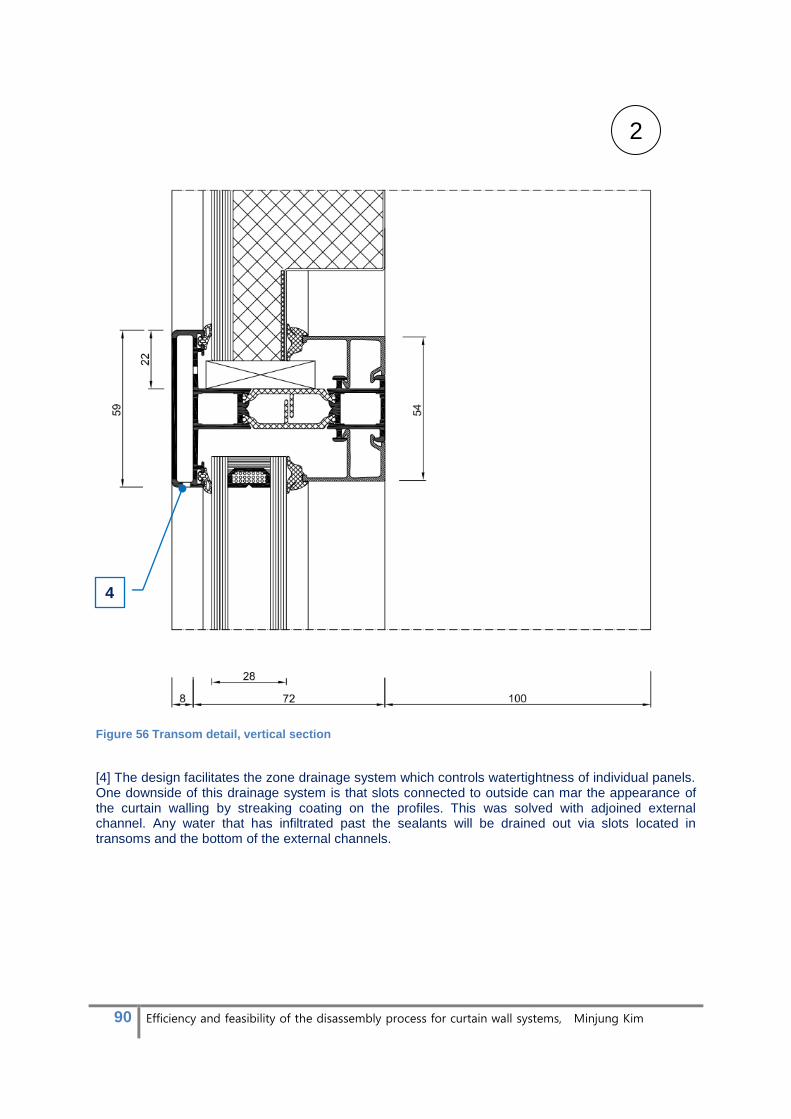
90 Efficiency and feasibility of the disassembly process for curtain wall systems, Minjung Kim
Figure 56 Transom detail, vertical section
[4] The design facilitates the zone drainage system which controls watertightness of individual panels. One downside of this drainage system is that slots connected to outside can mar the appearance of the curtain walling by streaking coating on the profiles. This was solved with adjoined external channel. Any water that has infiltrated past the sealants will be drained out via slots located in transoms and the bottom of the external channels.
4
2

91 Efficiency and feasibility of the disassembly process for curtain wall systems, Minjung Kim
Figure 57 Mullion to wall connection, horizontal
1. Double glazing
2. Gasket
3. Glazing bid
4. Aluminium-Plastic composite profile
5. Drainage slot
6. Drainage plate
7. Isolating membrane
8. Mullion mounting socket
9. Thermal insulation
10. Concrete floor
11. Steel plate
12. Spandrel panel,
dark glass pane glued to composite plate
13. Bracket
14. Steel angle
15. Concrete floor
16. Elastic seal
17. Steel angle
18. Floor construction: fabric floor covering,
screed, thermal insulation
19. Thermal insulation
20. Aluminium sheet cover
Figure 58 Ground connection, vertical
3
4

92 Efficiency and feasibility of the disassembly process for curtain wall systems, Minjung Kim
5
figure 59 Spandrel connection, vertical

93 Efficiency and feasibility of the disassembly process for curtain wall systems, Minjung Kim
Figure 60 Spandrel connection, vertical, without floor covering
5’
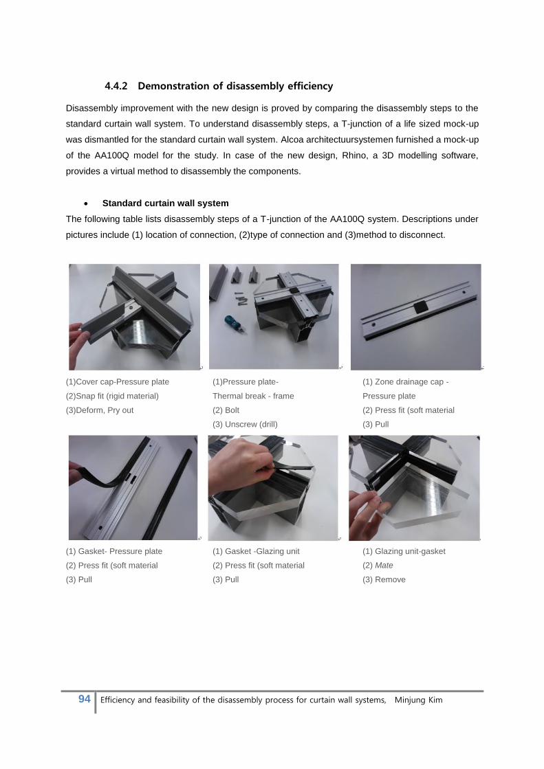
94 Efficiency and feasibility of the disassembly process for curtain wall systems, Minjung Kim
4.4.2 Demonstration of disassembly efficiency
Disassembly improvement with the new design is proved by comparing the disassembly steps to the
standard curtain wall system. To understand disassembly steps, a T-junction of a life sized mock-up
was dismantled for the standard curtain wall system. Alcoa architectuursystemen furnished a mock-up
of the AA100Q model for the study. In case of the new design, Rhino, a 3D modelling software,
provides a virtual method to disassembly the components.
Standard curtain wall system
The following table lists disassembly steps of a T-junction of the AA100Q system. Descriptions under
pictures include (1) location of connection, (2)type of connection and (3)method to disconnect.
(1)Cover cap-Pressure plate
(2)Snap fit (rigid material)
(3)Deform, Pry out
(1)Pressure plate-
Thermal break - frame
(2) Bolt
(3) Unscrew (drill)
(1) Zone drainage cap -
Pressure plate
(2) Press fit (soft material
(3) Pull
(1) Gasket- Pressure plate
(2) Press fit (soft material
(3) Pull
(1) Gasket -Glazing unit
(2) Press fit (soft material
(3) Pull
(1) Glazing unit-gasket
(2) Mate
(3) Remove

95 Efficiency and feasibility of the disassembly process for curtain wall systems, Minjung Kim
(1) Glass load bearing-
Gasket-Thermal break
(2) Mate
(3) Remove
(1) Gasket-frame
(2) Press fit(soft material)
(3) Pull
(1) Thermal break-frame
(2) Press fit (rigid material
(3) Pry out
(1) Drainage - Frame
(2) Mate
(3) Remove
(1) Transom -Mullion
(2) Bolt
(3) Unscrew (drill)
(1) Transom -Mullion
(2) Spring
(3) Deform and Pull
(1) Shear block-Transom
(2) Press fit
(3) Pry out and pull
(1) Gasket-mullion
(2) Mate
(3) Remove
Table 19 Disassembly of a T-junction of AA100Q model: Where, (1) location of connection, (2) type of connection and (3) method to disconnect
New design
A following table lists disassembly steps of a T-junction of new design. Descriptions under pictures
include (1) location of connection, (2) type of connection and (3) method to disconnect.
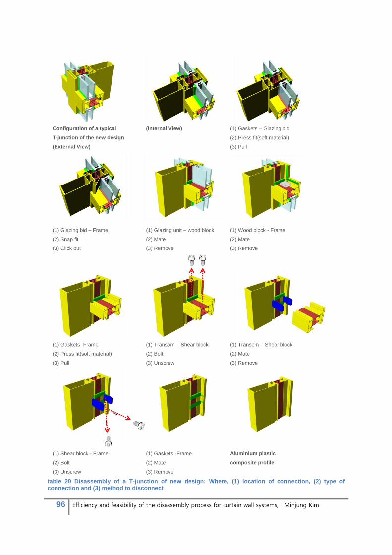
96 Efficiency and feasibility of the disassembly process for curtain wall systems, Minjung Kim
Configuration of a typical
T-junction of the new design
(External View)
(Internal View) (1) Gaskets – Glazing bid
(2) Press fit(soft material)
(3) Pull
(1) Glazing bid – Frame
(2) Snap fit
(3) Click out
(1) Glazing unit – wood block
(2) Mate
(3) Remove
(1) Wood block - Frame
(2) Mate
(3) Remove
(1) Gaskets -Frame
(2) Press fit(soft material)
(3) Pull
(1) Transom – Shear block
(2) Bolt
(3) Unscrew
(1) Transom – Shear block
(2) Mate
(3) Remove
(1) Shear block - Frame
(2) Bolt
(3) Unscrew
(1) Gaskets -Frame
(2) Mate
(3) Remove
Aluminium plastic
composite profile
table 20 Disassembly of a T-junction of new design: Where, (1) location of connection, (2) type of connection and (3) method to disconnect
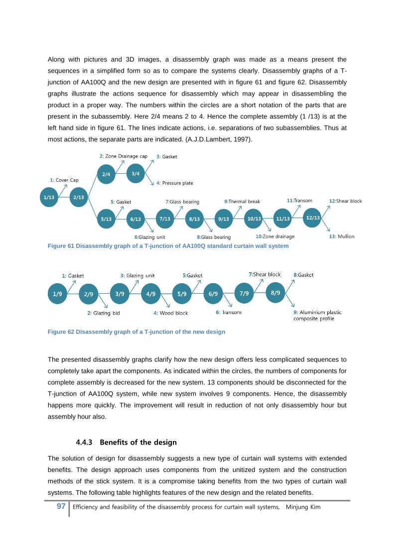
97 Efficiency and feasibility of the disassembly process for curtain wall systems, Minjung Kim
Along with pictures and 3D images, a disassembly graph was made as a means present the
sequences in a simplified form so as to compare the systems clearly. Disassembly graphs of a T-
junction of AA100Q and the new design are presented with in figure 61 and figure 62. Disassembly
graphs illustrate the actions sequence for disassembly which may appear in disassembling the
product in a proper way. The numbers within the circles are a short notation of the parts that are
present in the subassembly. Here 2/4 means 2 to 4. Hence the complete assembly (1 /13) is at the
left hand side in figure 61. The lines indicate actions, i.e. separations of two subassemblies. Thus at
most actions, the separate parts are indicated. (A.J.D.Lambert, 1997).
Figure 61 Disassembly graph of a T-junction of AA100Q standard curtain wall system
Figure 62 Disassembly graph of a T-junction of the new design
The presented disassembly graphs clarify how the new design offers less complicated sequences to
completely take apart the components. As indicated within the circles, the numbers of components for
complete assembly is decreased for the new system. 13 components should be disconnected for the
T-junction of AA100Q system, while new system involves 9 components. Hence, the disassembly
happens more quickly. The improvement will result in reduction of not only disassembly hour but
assembly hour also.
4.4.3 Benefits of the design
The solution of design for disassembly suggests a new type of curtain wall systems with extended
benefits. The design approach uses components from the unitized system and the construction
methods of the stick system. It is a compromise taking benefits from the two types of curtain wall
systems. The following table highlights features of the new design and the related benefits.

98 Efficiency and feasibility of the disassembly process for curtain wall systems, Minjung Kim
Design feature Design benefits
The assembly is carried out with the
construction principle of stick systems
Possibility of site adjustment
Flexibility to design change
The system is built from inside Constructability despite of violent weather
condition
Components in knock down form does not
demand the aid of heavy machinery to lift them Save in cost for lifting equipment on site
Assembly of profiles are finished in factory to
some extent to ensure the structural integrity. It
reduces the number of components for the
assembly and the disassembly.
Reduction in site assembly/disassembly time
and labour cost
The assembly is completed in the construction method of the stick system which is the most widely
used type. It renders another benefit that there would be little conflict in adopting the new system in
reality. Accumulated knowledge, skilled labour and installation techniques for stick systems will be
simply fed into the construction work of the new system.

99 Efficiency and feasibility of the disassembly process for curtain wall systems, Minjung Kim
4.5 Design conclusion
The design process was dedicated to improve disassembly for future curtain wall systems. It is carried
out by solving problems uncovered during previous study of disassembly details and its feasibility
assessment. Design strategies were established within a feasible scope in relation to product design.
The main concept which encompasses the strategies can be determined as “curtain wall system 180°
rotated, possible to be constructed inside out and designed by the reconfiguration of existing
components”. The design goal was achieved through the modification of existing window systems.
The development of the design encountered several challenges, including enhancement of structural
performance, minimizing structural appearance, detailing T-junction and drainage. The various
solutions were integrated into the final design. The detailing is illustrated via drawings of the typical
section and the applications. Finally, the design improvement in regards to disassembly was verified
by comparing the design steps of the new system to the conventional approach. The results showed
that merely through the reconfiguration of existing components, curtain wall systems can be obtained
with ease of disassembly. This indicates there are a large number of possibilities for the future when
the system is completely redesigned.

100 Efficiency and feasibility of the disassembly process for curtain wall systems, Minjung Kim
5. Recommendations/Future work
The research has raised as many issues on disassembly as it has addressed. Recommendations for
addressing some of these issues have been divided into two sections. The first section focuses on
suggestions for other design approaches for improved disassembly and the second section provides
recommendations for governments and societies to encourage constant improvement of disassembly.
5.1 Unitized concept
Design strategies to improve disassembly in this research were based on principles of stick systems
because the systems take a dominant position in the market of curtain wall systems. Other
construction methods, however, should be studied to suggest various design options for the future.
Unitized systems provide a simple method of on-site construction which enables achieving rapid
assembly and disassembly. In the method, the entire system wall is prefabricated off site and the
complete systems are stacked together on site like building a Lego house. Theoretically, applying the
method would realize efficient disassembly in a simpler way than the method of stick systems. The
approach, however, has some disadvantages which has limited the applications in reality.
• High level of logistical investment (e.g. Cranes to lift up the heavy systems)
• Possible damage during transporting complete systems
• Complex joints which connect different materials tight
The last point, especially, presents a particular challenge to recycle the unitized system in efficient
ways. Most of the systems are assembled with complex assemblies and with different parts often
bonded together so that they cannot be disassembled easily or at all [Figure 63]. If it takes too long for
workers to separate the parts, they will not do it but discard them in a conventional way which
includes multiple steps of cleaning, shredding and sorting processes to recover the materials. It
results in a situation of opposing goals wherein the system is particularly efficient for disassembly on
site but the complete disassembly is nearly impossible. In addition, the unitized system likely will not
get repaired often (or ever) for the same reason, which makes them difficult to endure or reuse. This
is why producers manufacture extra numbers of the systems and throw away damaged systems
occurred during the usage period or transportation.

101 Efficiency and feasibility of the disassembly process for curtain wall systems, Minjung Kim
Figure 63 Alcoa AA9562 system presents complex corner details; Multiple assemblies are bonded with glue or tightened with bolts which require a custom tool to disassemble them.
Nethan Shedroof on ‘Design is the problem’ in 2011 discussed the same problem and suggested
eight techniques to increase the recyclability which should be taken into account in the initial phase of
the design. Three techniques are learnt from the book and integrated into the design strategies for a
new system with a unitized concept.
1) Pure-material parts: These are parts made from only one material that do not need to be
separated. For most products, it’s unlikely that the whole product can be made from the same
material, but if a product’s parts are at least uni-material, then each can be recycled easily.
2) Fewer parts: Where possible and applicable, reducing the number of parts can reduce the
time and cost of disassembly and also affect the overall environmental impact by potentially
reducing the amount of materials used.
3) No fasteners: Sometimes, cases and components can be designed to clip together without
the need for fasteners like screws. For example, many mobile phone cases (like those for the
Nokia 6200) do this to allow a plethora of third-party custom case designs. The Macintosh
IIcx and IIci family excelled in this respect as well. Hard drives, fans, power supply,
motherboard, and other components simply snapped into place with plastic tabs molded into
the case itself. These bent just enough to allow them to be held aside for the components to
be removed. Parts can be glued or bonded, but only where they are recyclable together
because they are identical materials.(Shedroff, 2011)
Consideration of the problems and techniques formulates main design strategies for disassembly with
unitized concept.
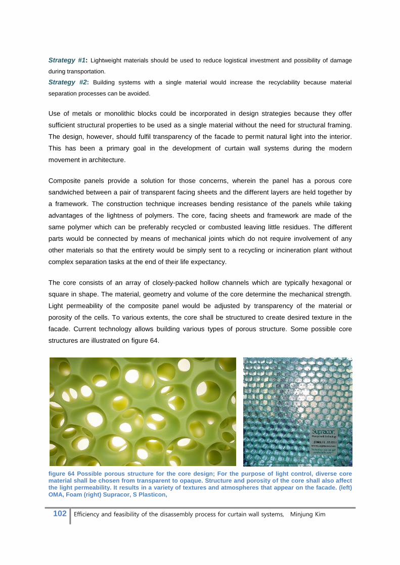
102 Efficiency and feasibility of the disassembly process for curtain wall systems, Minjung Kim
Strategy #1: Lightweight materials should be used to reduce logistical investment and possibility of damage
during transportation.
Strategy #2: Building systems with a single material would increase the recyclability because material
separation processes can be avoided.
Use of metals or monolithic blocks could be incorporated in design strategies because they offer
sufficient structural properties to be used as a single material without the need for structural framing.
The design, however, should fulfil transparency of the facade to permit natural light into the interior.
This has been a primary goal in the development of curtain wall systems during the modern
movement in architecture.
Composite panels provide a solution for those concerns, wherein the panel has a porous core
sandwiched between a pair of transparent facing sheets and the different layers are held together by
a framework. The construction technique increases bending resistance of the panels while taking
advantages of the lightness of polymers. The core, facing sheets and framework are made of the
same polymer which can be preferably recycled or combusted leaving little residues. The different
parts would be connected by means of mechanical joints which do not require involvement of any
other materials so that the entirety would be simply sent to a recycling or incineration plant without
complex separation tasks at the end of their life expectancy.
The core consists of an array of closely-packed hollow channels which are typically hexagonal or
square in shape. The material, geometry and volume of the core determine the mechanical strength.
Light permeability of the composite panel would be adjusted by transparency of the material or
porosity of the cells. To various extents, the core shall be structured to create desired texture in the
facade. Current technology allows building various types of porous structure. Some possible core
structures are illustrated on figure 64.
figure 64 Possible porous structure for the core design; For the purpose of light control, diverse core material shall be chosen from transparent to opaque. Structure and porosity of the core shall also affect the light permeability. It results in a variety of textures and atmospheres that appear on the facade. (left) OMA, Foam (right) Supracor, S Plasticon,

103 Efficiency and feasibility of the disassembly process for curtain wall systems, Minjung Kim
The chosen polymers for this design concept should be available in transparent or translucent colours
and provide material properties to stand up to weathering. The example materials would be
Polycarbonates and Polyester, if necessary, reinforced by fibre glass and coated by a UV protection
layer. There already are available products on the market using the materials for applications of
facade construction. Figure 65 illustrates one of the examples from Rodeca GmbH. Their wall
elements are manufactured from polycarbonate, a thermoplastic material 200 times stronger than
glass. The elements are formed in a section of several rectangular champers to increase the bending
resistance and the insulation value. The thermal performance also is known to be as high as general
double glazing units which is U < 1.1W/m2K. Some panels over thickness of 60mm provided lower U
value, approx. 0.87 W/m2K. The material choice also has a downside that combined effect of sunlight
and UV coating often fades colours and mars the outside appearance. 10-Years are assumed as a
guarantee period against the damage. (Rodeca) The solution would be replacing the damaged panel
with a new one, which may increase the amount of waste. Environmental impact through the life cycle
of the panels, however, will be less than standard unitized curtain wall systems if it achieves the
design concept well. In addition, development of a new material which is resistant to sunlight should
be investigated in the future.
Figure 65 An example of polycarbonate panels applied for facade construction. Fatima Mansion in Dublin is rain screened with BICOLOR panels in colour combination crystal and opal. Delivered by Rodeca GmbH.
A new design with the composite concept is illustrated in following drawings from figure 66 to figure
70. The construction basically consists of 4 parts; composite panels, gaskets, steel brackets and steel
angles. The composite panel is completed in shop where facings, core and framework already are
assembled. Gaskets are applied around the edge of the panels, which will keep out the weather and
allow structural movements of the systems to a certain extent. The assembly process is designed to
be as simple as possible so as to minimize the disassembly hours. Once the brackets and the angles
are fixed to concrete floors, composite panels are mounted in principles of a tongue and groove
connection. Small pieces cut off in a square shape from both the upper and the bottom of the panels a
little distance from where the brackets should be fixed. The panels then are fitted onto the brackets

104 Efficiency and feasibility of the disassembly process for curtain wall systems, Minjung Kim
from the front and slided to a side being fixed in desired positions [Figure 69]. As illustrated in
construction diagram of figure 69, small parts are protruding on one vertical side of the panels, which
sustain the connection between neighbouring panels and secure them from extreme deformation.
Figure 66 Unitized concept, vertical section
1. Composite panel, finished with UV protection coating
2. Steel beam, covered with rubber 3. Steel angle 4. Concrete floor 5. Gasket 6. Polymer frame, integrated in
composite panel 7. Steel plate, covered with rubber
8. Polymer facings
9. Polymer core
Figure 67 Unitized concept, horizontal section
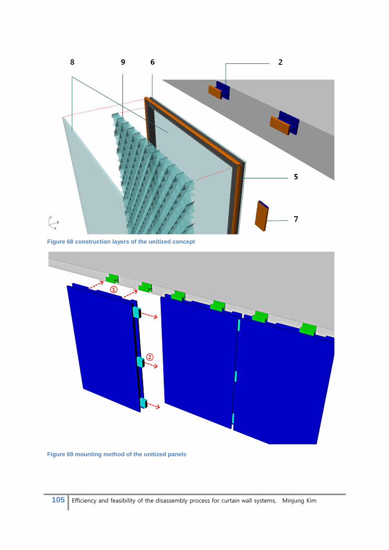
105 Efficiency and feasibility of the disassembly process for curtain wall systems, Minjung Kim
Figure 68 construction layers of the unitized concept
Figure 69 mounting method of the unitized panels
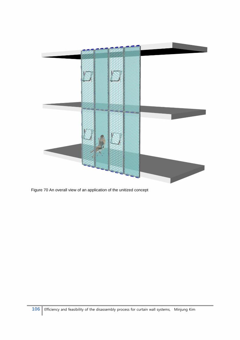
106 Efficiency and feasibility of the disassembly process for curtain wall systems, Minjung Kim
Figure 70 An overall view of an application of the unitized concept

107 Efficiency and feasibility of the disassembly process for curtain wall systems, Minjung Kim
5.2 Recommendations for governments and societies
The solutions to improve disassembly so far have been discussed in regards to product design of
curtain wall systems. As addressed during the research, however, obstacles regarding the feasible
disassembly are complex and it therefore requires collaborative implementation across disciplines.
Many stake holders are involved in the processes from the design for disassembly to the trade in
used components. While conventional practices for EoL curtain wall systems already have been
structured for maximum profit within the boundaries of environmental legislations, introduction of
disassembly will cost them a high level of investment and will be a shake-up, which may lead them to
sustain conventional methods. Therefore a range of intervention, by government, societies and
industrial players, should be facilitated to enforce environmental justice as well as guarantee them
profit from implementing disassembly. Despite other possible solutions, in this paragraph, two
solutions will be proposed for the issues;
Enhance the reuse market of used components of curtain wall systems
Bring legal action to encourage disassembly
5.2.1 Enhance the reuse market
As discussed in section 3.2 the economic assessment, absence of secondary market for curtain wall
systems presents a primary challenge in cost-effective disassembly. When considering the low value
of scraps and the increasing levies for landfills, revenue from the sale of used components is
expected to be an economic incentive for disassembly, despite the increased labour cost. There is,
however, no apparent market to trade the used components. Resale value of the second-hand
components thus cannot be estimated and the economic feasibility is unclear.
The durability of the components is not doubted but the possibility of successful sale of the
components is. Some components of curtain wall systems, like aluminium profiles and IGU, are
possible for being reused because of their long life span. That already has been illustrated through
the market for used windows (refer to paragraph 2.2.2.3). The curtain wall components, however, are
not likely to be purchased by developed countries due to high standards of facade installation which
have been raised ever since curtain wall systems have been introduced. Performance of post-
consumed components can be inferior to the present requirement because the systems were
designed for the standard of some decades ago.
The possible solution would be stimulating global trade between developed and developing countries.
The used components can be legitimately reused abroad because a majority of developing countries
is still developing the facade standards and often feature less strict requirements. Second-hand
windows already flow from developed to developing countries, which illustrates there are feasible
markets and customers who are willing to buy products with advanced technologies despite their
previous usage period.

108 Efficiency and feasibility of the disassembly process for curtain wall systems, Minjung Kim
Global trade of used components of curtain wall systems would require organizations which regulate
the quality and connect buyers and sellers. Education on the construction and materials for upgrading
and maintenance (gaskets, thermal break for example) must be provided at the same time to ensure
the performance of the implementation in different locations.
The trade network should be equipped with identification systems of the components. No matter how
the parts are easily disassembled, if usage history and technical information are not given, it will be
difficult to reuse them for appropriate implementations. If the facade constructors do not know if the
components are from a specific company among a large number of manufacturers, for example, they
would not know how to install them and according to which specifications. Thus components should
be marked with labels which can be understood by identification systems. For plastics, there are
already commonly understood labels for this purpose. Likewise, the system should be extended to
glass and aluminium which we are considering for reuse.
Figure 70 proposes a possible solution in which the existing 2D barcode system is integrated into the
extrusion process of aluminium profiles. Once the identification system is established for the
components of curtain wall systems, the reuse of secondary parts will become more efficient and
reliable.
Figure 71 (left) Identification systems for other products; plastic recycling label, 2D barcode and 3D barcode system, (right) the 2D barcode system could be integrated into extrusion process of aluminium profiles.

109 Efficiency and feasibility of the disassembly process for curtain wall systems, Minjung Kim
5.2.2 Extended Producer Responsibility (EPR)
The disassembly implementation should be reinforced by environmental jurisdiction and EPR. Most
waste-related policies in recent years have been based on the EPF principle which requires
producers to take financial responsibility for end-of-life of their products.
EPR includes policies from mandatory or voluntary take-back to disassembling and recycling fees and
fees on disposal. It shifts the responsibility upstream from municipalities to producers. In the scheme,
the true cost of waste management is internalized within the retail price by the producer. The aim is to
provide an incentive to produce products that are cheap and easy to disassembly and recycle. In turn,
it drives companies to achieve innovation, such as in business models, take-back logistics and design,
to reduce the environmental impact of products. (Lundgren, 2012)
Experiences from other industries already proved that EPR policies could drive green design of
products. In European countries under EU Directive compliance, the EPR widely has been acting on
electronics and automotive industries where the waste management issue is more critical than the
facade industry because of the involvement of hazardous materials. While dealing with their own
product waste, the companies realized that they will have more incentive to simplify the disassembly
and recycling process or to prolong the lifespan. One of the examples is the prototype of Bloom laptop,
designed by a group of students from Stanford University and Aalto University in Finland. It can be
completely disassembly by hand without any tools, making upgrading easier by simply replacing parts
and recycling the device. BMW also established their reclamation processing for ease of disassembly.
All pyrotechnical components (airbags, belt tensioners, etc.), for example, are simplified to shorten the
disassembly and recovery process. Recovered components are incorporated in design consideration
even before a new model enters production.
As exemplified by other industries, introducing EPR into curtain wall industries would contribute to
enforcing constant improvement of disassembly by imposing increased responsibility on producers for
the end-of-life issues. In the end, it could result in reduced pollution and better resource management.
Figure 72 (left) Bloom laptop, (right) Recycled plastics (shown in green) in the BMW 3-series
110 Efficiency and feasibility of the disassembly process for curtain wall systems, Minjung Kim
6. Conclusion
As has been illustrated and proven throughout this research, disassembly should be accepted as an
important end-of-life treatment for curtain wall systems because it allows maximum recovery of
components and materials. The environmental benefits accompanied with disassembly are estimated
to bring forth a significant reduction in the amount of emission during the EoL phase of curtain wall
systems. A complete result could not be reached for the economic impact of disassembly due to
some uncertain data for cost. When thinking in terms of the life-cycle, however, increased labour
expense from the operation will be offset by profits from component and material retrieval. Additionally,
considerations for disassembly made during the design phase will make the implementation more
cost effective by developing curtain wall systems to be dismantled in a minimal time span.
Detailed studies of disassembly design and its implementation for curtain wall systems are still in their
infancy. It is anticipated, however, that in the foreseeable future, building regulations associated with
the waste management and the use of resources will be expanded and strengthened. It will motivate
and facilitate the type of efficient disassembly which is necessary for the contemporary building sector.
This approach has been proven effective in various other disciplines and should now be adopted in
this brand new field.

111 Efficiency and feasibility of the disassembly process for curtain wall systems, Minjung Kim

112 Efficiency and feasibility of the disassembly process for curtain wall systems, Minjung Kim
7. Literatures
(EAA), E. A. A. (2004). Collection of Aluminum from Buildings in Europe: Delft University of Technology A.J.D.Lambert. (1997). Optimal disassembly of complex products. International Journal of Production
Research, vol. 35(no. 9, 2509± 2523). Alcoa-architectuursystemen. AA 100 Q Aluminium Curtain Walls Retrieved May 1st, 2013, from
http://www.alcoa.com/bcs/architectuursystemen/en/product.asp?cat_id=609&prod_id=4084 Althaus, H.-J., Kellenberger, D., Classen, M., & Thalmann, P. (2007). Life cycle inventories of Building
products: Part XIV Insulation Products and Processes. Beatriz Rivela, M. T. M., Ivan Munoz, Joan Rieradevall, Gumersindo Fuijoo. (2005). Life cycle assessment
of wood wastes; A case study of ephemeral architecture. Beelen-groep. Demolition of the University of Amsterdam Retrieved April 26, 2013, from
http://www.beelen.nl/index.php/beeleninbeeld/project/83 Building-department. (2004). Code of Practice for Demolition of Buildings: The Government of the Hong
Kong Special Administrative Region. Ch.F.Hendriks, & Janssen, M. G. M. T. (2001). Construction and demolition waste: general process
aspects. (46). Retrieved from http://heronjournal.nl/46-2/1.pdf Civil-Engineering-and-Development-Department. (2004). Guidelines for selective demolition & on site
sorting. Guidelines for selective demolition & on site sorting. Coventry, S. (1999). The reclaimed and recycled construction materials handbook. london: Construction
Industry Research and Information Association. CSI. (2012). A Global king of curtain wall in steady growth. Hong Kong: CSI, Synovate D.Elcock. (2007). Life-cycle thinking for the oil and gas exploration and production industry: Environmental Science Division. DWMA, D. W. M. A. Waste-to-Energy in the Netherlands. Retrieved April 26, 2013, from
http://www.wastematters.eu/about-dwma/activities/waste-to-energy/activities-in-the-netherlands.html
EAA. (2007). Aluminium Recycling in LCA. Eriksson, O., & Finnvenden, G. (2009). Plastic waste as a fuel - CO2-neutral or not? Fleur van Broekhuizen, H. v. E. (2010). Slim slopen tool, CO2/NOx in de keten van slopen, logistiek en
hergebruik/toepassing: IVAM. Gabor Daka, D. l. c. a. (2009). Life cycle inventories of waste treatment services, part V Building material
disposal. Gupta, A. J. D. F. L. a. S. M. (2004). Disassembly Modeling for Assembly, Maintenance, Reuse and
Recycling, CRC press. Guy, B. Building Deconstruction: Reuse And Recycling Of Building Meterials. In C. f. C. a. Environment
(Ed.). Florida USA: University of Florida. Guy, B. (2003). A guide to deconstruction. Florida USA: Florida Center for Construction and Environment M. E. Rinker, Sr, School of Building Construction College of Design, Construction and Planning.

113 Efficiency and feasibility of the disassembly process for curtain wall systems, Minjung Kim
Hans-Jorg Althaus, E. (2009). Life cycle inventories of Metal, Part I Aluminum. JUNGMEIER, G., WERNER, F., JARNEHAMMAR, A., HOHENTHAL, C., & RICHTER, K. (2002).
Allocation in LCA of woodbased products. Kawneer. (1999). Principles of curtain walling. Lehmann, M., Althaus, H.-J., & Empa. (2007). Ecoinvent report No.7; Glazing, Window, Frames, Claddings
and Doors. Lundgren, K. (2012). The global impact of e-waste, addressing the challenge. International Labour Office
Geneva. M.Asif, T. M., R.Kelly. (2007). Life cycle assessment: A case study of a dwelling home in Scotland. Building
and Environment 42. Mantia, F. P. L. (2002). Handbook of plastics recycling: Technology & Engineering. Martin Lehmann, H.-J. A., Empa. (2007). Life cycle inventories of building product, part XXVI Glazing,
Window frames, Claddings and Doors. Mathlener, R. A., Heimovaara, T., Oonk, H., Luning, L., & Sloot, H. A. v. d. (2006). Opening the Black Box:
Process-Based Design Criteria to Eliminate Aftercare of Landfills: Dutch sustainable Landfill Foundation.
Michael Spielmann, C. B., Roberto Dones, Matthisa Tuchschmid. (2007). Life cycle inventories of transport
services. Nahb Research Center, I., & Upper Marlboro, M. (1997). Deconstruction-Building Disassembly And
Material Salvage: The Riverdale Case Study. Nave, R. (2012). Parallel Axis Theorem. Retrieved May 7th, 2013 Paola Villoria Saez, e. a. (2011). European Legislation and Implementation Measures in the Management
of Construction and Demolition waste. Pritchard, G. (1998). Plastics Additives: An A-Z reference. London: Chapman & Hall. REDWAVE. Optical Glass Sorting Machine. from http://www.redwave.at/en/about-redwave/the-
company.html Rodeca. Rodeca, Translucent building elements. Retrieved June 17th, 2013, from http://www.rodeca.de/ Shedroff, N. (2011). Design is the problem: O'Reilly Media, Inc. Symonds, i. a. w. A., COWI and PRC Bouwcentrum. (1999). CONSTRUCTION AND DEMOLITION
WASTE MANAGEMENT PRACTICES, AND THEIR ECONOMIC IMPACTS. Tyabji, N., & Nelson, W. (2008). Mitigating Emissions from Aluminum: The Global netwrok for climate
solutions. Ulrich Knaack, T. K., Marcel Bilow, Thomas Auer. (2007). Facades_ Principles of Construction. W.Y.Tam. (2006). A Review on the Viable Technology for Construction Waste Recycling. WNA. (2011). Comparison of Lifecycle Greenhouse Gas Emissions of Various Electricity Generation
Sources: World Nuclear Association.

114 Efficiency and feasibility of the disassembly process for curtain wall systems, Minjung Kim