effects of some technological aspects on the fatigue strength of a cementless hip stem
TRANSCRIPT
Effects of some technological aspects on the fatigue strength of a cementless hip stem
Marco Viceconti,',* Aldo Toni,',' and Armando Giunti',' 'Biornaterials Technology Laboratory and 'Orthopaedic Clinic of University of Bologna, lstituti Ortopedici Rizzoli, Bologna, Italy
Four prototype cementless hip stems were tested following the IS0 7206 protocol for the assessment of the endurance properties and compared with a cast Cr-Co-Mo (ASTM F75) commercially available stem which was used as refer- ence design. All the tested stems were similar in shape and size, but with some substantial differences. The first was made of forged Ti6A14V alloy (ASTM F136). The second, made of the same material, featured a central hole intended to reduce the bending stiffness of the stem itself. The third was identical to the second but for a small tooling notch in one of the fillets of the hole. The fourth was similar to the
first but had a coating of sintered titanium beads in the proximal part. All of these modifications were made to eval- uate the effect of fatigue strength of intentional or uninten- tional features commonly found in commercial stems. The forged Ti6A14V alloy was found to be substantially stronger than the cast ASTM F75 Cr-Co-Mo alloy. However, tooling notches or sintered coatings were found to dramatically reduce this strength. Thus, the Ti6A14V alloy calls for an accurate design process, especially when complex shapes or sintered structures are required. 0 1995 John Wiley & Sons, Inc.
INTRODUCTION
In vivo fatigue fracture of the femoral component in total hip arthroplasties have been frequently re- ported. Fatigue failure of cemented stems reported in the literature for Charnley stems indicated an inci- dence rate of 0.23%,l 0.69%,2 2.4%,3 and 4.3%.4 For other cemented designs, the incidence was even higher, up to 6% .5 Failure was reported not only for steel stems, but also for cast Cr-Co-Mo stems6 and for a forged vitallium stem.7 Fatigue fractures were reported also for cementless stems by Engh and Massin,' giving an incidence rate of 0.5% over 5 years, and by Wilson et al.,'with an incidence of 4.1% over 4 years. Stem loosening is usually indicated as a decisive factor in stem failure," particularly in the case of active and overweight patients." Although fractures are usually observed in small-size stems, fractures of larger stems have occasionally been re- ported.12 Even high-strength materials such as Ti6A14V can occasionally fail as a result of design er- rors or unpredictable stress raisers, sometimes re- lated to mesh pads or porous coatings.'
*To whom correspondence should be addressed at Isti- tuti Ortopedici Rizzoli, Laboratorio di Tecnologia dei Ma- teriali, via di Barbiano 1/10, 40136 Bologna, Italy.
The continuous development of new stem designs, mainly focused on addressing "modern" problems such as stress shielding or primary stability criteria, cannot ignore the first requirement for every en- doprosthesis: absolute absence of in vivo mechanical failure under any condition. To check the fulfillment of this primary requirement, the most commonly used in vitro test is the load on head (LOH) fatigue test. It is a bending fatigue test in which the distal part of the stem is cemented in a given position and a cyclic load is applied to the prosthetic head. Al- though sometimes critici~ed,'~ the LOH approach is shared by different national (BS, DIN, UNI, etc.) and international (ISO) standardized testing protocol^.^^ Thus, its relevance cannot be disregarded. However, since the LOH test was defined by adherence to wide clinical experience with cemented stems, it needs some extensions to be applicable for cementless stems.
MATERIALS AND METHODS
I S 0 7206/3 standard procedure
Journal of Biomedical Materials Research, Vol. 29, 875-881 (1995) 0 1995 John Wiley & Sons, Inc.
The IS0 standard on the determination of the en- durance properties of stemmed femoral components
CCC 0021-9304/95/070875-07
876 VICECONTI ET AL.
(IS0 7206/3, 1988) was assumed as a reference in the present work.
The standard is based on the following assump- tions:
0 The anatomical axis of the femur is assumed to be at an angle of 10" to the load line, when viewed perpendicular to the plane that includes the stem and the neck.
0 Because of the complexity of the dynamic load pattern in the patient, the diverse geometry of the hip prosthesis, and the operative technique at implantation, certain factors are not referred to in this part of IS0 7206.
0 The test conditions are based on the assumption that the stem of the prosthesis has become un- supported through breakdown of the proximal cement or bone.
From the IS0 standard indications, the following procedure was deducted. The head of the stem under testing was held, by means of a gripping device, in a position so that the main axis of the stem was inclined at an angle of 10" to the vertical. Then, the specimen was slowly lowered into the embedding medium (contained in a stainless-steel cup called a specimen holder) until the center of the head was at a vertical distance of 80 rt 2 mm from the embedding medium- free surface. The stem was held in position until com- pletion of medium solidification. Every specimen was loaded only a week after the embedding, allowing the medium to complete the hardening.
A methyl methacrylate-styrene copolymer resin was used as embedding medium (Res-tray, S.P.D., Milano, Italy). The suggested powder-to-liquid ratio of 7 3 was adhered to. During preliminary tests Res- tray cement presented a 0.2% offset stress of 51 rt 6 MPa and a module of elasticity of 3078 & 330 MPa.
All the tests were run in a buffered Ringer's bath (Ringer acetate) maintained at a temperature of 37 k 1°C and permanently insufflated with air. During the test the solution was slowly changed to maintain chemical activity.
The gripping device and specimen holder were de- signed to ensure the alignment between the testing machine load axis and the center of the prosthetic head. The testing machine was equipped with a sup- port plate which allowed an accurate alignment of the specimen holder and a loading head able to transmit the load only in the vertical direction. After position- ing, the test specimen was immersed in the fluid test medium and then loaded with a sinusoidal cycle ranging between 300 N and the maximum load. The testing machine was operated at a frequency of 10 Hz, the recommended value for metallic specimens. The specimen was considered to be broken when a displacement >125% of that measured 10 min after the test initiation occurred, or when the minimum compressive load became 4 0 0 N.
The staircase approach
The IS0 7206/3 defines the full protocol for testing but leaves undefined the maximum load to be ap- plied. Another part of the standard (IS0 7206/7, 1993) indicates the minimum endurance performance in an application of 5 X lo6 load cycles between 300 and 3300 N with no failure.
The present test campaign was performed using a systematic decreasing load approach (staircase test) to obtain an estimate of the fatigue limit for each stem. The protocol starts with a static test to define the upper load limit. Then, fatigue tests designed af- ter I S 0 7206/3 are performed with decreasing maxi- mum loads. The first load is assumed as one body weight (BW = 700 N) less than the measured yield load. The fatigue test is repeated reducing the load (by one BW) until the stem can endure at least 5 mil- lion load cycles. If the fatigue limit is below 5 BW, the stem is rejected.
Design features under evaluation
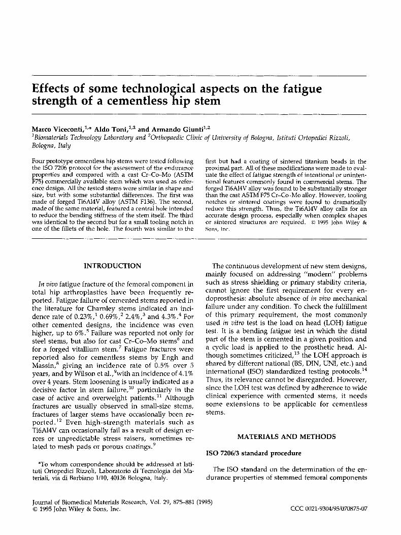
The proposed protocol was applied to four differ- ent cementless stem designs. The first was a commer- cial ASTM F75 Cr-Co-Mo alloy anatomical stem (An.C.A. THR, mini size, Cremascoli s.r.l., Italy). Among the available sizes, the smallest (mini) was used (Figure la). The An.C.A. stem is now widely used in Italy; 7 years after its introduction, and with more than 1000 stems implanted, no in vivo stem frac- tures have been reported. The other three tested stem designs were modifications of the first one.
The second was shaped exactly as the An.C.A. stem, but made of ASTM F136 titanium alloy (Figure lb). This test facilitated the comparison of material properties separate from geometry influences.
The third was produced from the second by ma- chining a central anteroposterior hole, aimed at re- ducing bending stiffness of the stem (Figure lc). The hole dimension was preliminarily defined using a fi- nite element analysis. The final design presented the nominal stress in the same location and with the same magnitude as that of the whole stem. Thus, the holed stem was expected to perform as the whole stem.
The fourth design was also obtained from the sec- ond one with the application of a porous coating of titanium-sintered beads extended distally to the cy- lindrical section of the stem, corresponding with the distal border of the mentioned hole (Figure Id). The porous-coated stem tested as usual and after two pat- ented industrial thermal treatments (B.U.S. and S.T.A.) which should increase the strength of the coated material and reduce the level of residual
FATIGUE STRENGTH OF CEMENTLESS HIP STEMS 877
Figure 1. smooth stem (b), forged TibA14V-holed stem (c), forged Ti6A14V bead-coated stem (d).
The four stem types tested in the present work. Left to right: cast Cr-Co An.C.A. ministem (a), forged Ti6A14V
stresses due to the sintering process. Both the ther- mal treatments are basically formed by a high vac- uum hardening followed by a tempering cycle. In the S.T.A. treatment the tempering cycle has a duration of 2 h while the B.U.S. treatment has a duration of 8 hours coupled with a higher tempering temperature.
Fatigue limit estimation
Because it is an asymptotic property, the fatigue limit (i.e., the highest cyclic stress endured by the stem without failure) cannot be directly measured but only estimated. In the present case there were two problems: to convert the external applied load in terms of maximum induced stress and to extrapolate the fatigue limit from finite life tests (stress level to which the specimen fails before the 5th million cycle).
To translate loads to stresses, a strain gauge anal- ysis was performed to determine the highest tensile stress (which for the IS0 720613 is normally located on the lateral side) under a given static load. For each stem design under testing, seven strain gauges (LY11, H.B.M., Germany) were placed (before em- bedding) on the stem lateral aspect, at 50, 60, 70, 80, 85, 90, and 95 mm from the head center. Being the embedding level at 80 mm, one of the gauges was
partially and another three completely covered by the embedding medium. A first test with rosettes showed that the nonvertical components of the mea- sured strains were negligible; thus, the other tests were made using monodirectional strain gauges, aligned with the main axes of the stem. The instru- mented stem was subjected to a static load and from the highest recorded strain a correlation was made between applied load and induced stress. Care was taken to operate the measurement well below the elastic limit of the stem material. This correlation was used in the following to represent the fatigue tests results in terms of stresses. It must be noted that the stresses reported below were not directly measured, but calculated assuming that the correlation between external load and induced stresses, as measured for a static load, was still valid when a cyclic load was ap- plied. Thus, they must be considered as reference stresses, useful to eliminate the dependency of stem geometry from the results.
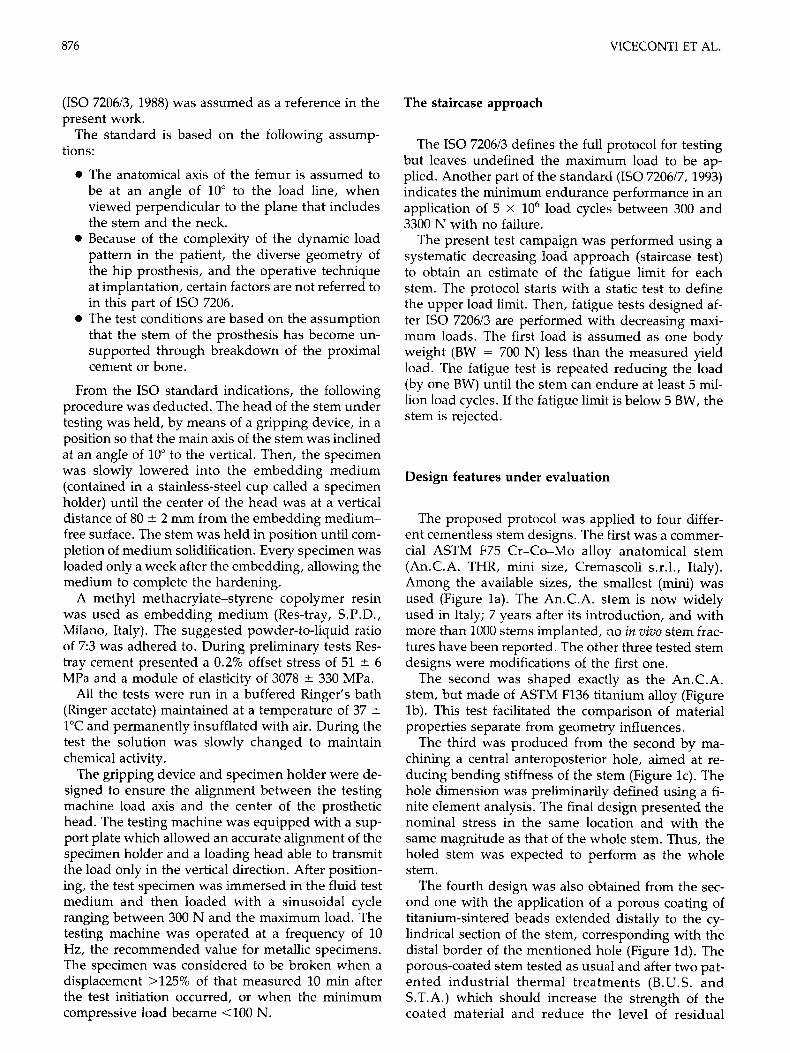
The estimate of the fatigue limit was calculated making two assumptions: a log-log relationship be- tween stress and specimen life occurs; a specimen which reached 10 million cycles without failure would not fail with any further cycling. For every stem type, all the results were reported in a log(us)- log(N) diagram and the data points were fitted with a linear function (on log-log scale). The intercept of this
878 VICECONTI ET AL.
regression with the N = 10,000,000 cycles axis was assumed to be the fatigue limit. Its variance was es- timated with the 99.9% confidence limits of the linear regression slope (confidence interval). Figure 2 shows these regressions for the full Ti stem.
RESULTS
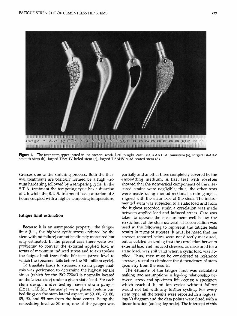
Figure 3 compares the measured fatigue strength of the Cr-Co mini An.C.A. stem (472 +- 45 MPa) with the Ti equivalent stem (600 2 35 MPa). All of these specimens failed with a horizontal fracture 5-10 mm below the cement surface. These results were in agreement with the strain gauge analysis, which al- ways indicated the highest tensile stress Iocation be- tween 85 and 90 mm from the head.
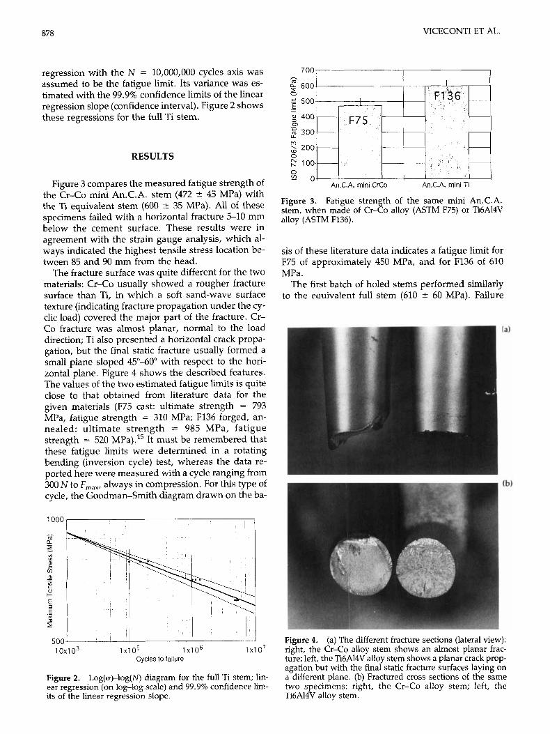
The fracture surface was quite different for the two materials: Cr-Co usually showed a rougher fracture surface than Ti, in which a soft sand-wave surface texture (indicating fracture propagation under the cy- clic load) covered the major part of the fracture. Cr- Co fracture was almost planar, normal to the load direction; Ti also presented a horizontal crack propa- gation, but the final static fracture usually formed a small plane sloped 45"-60" with respect to the hori- zontal plane. Figure 4 shows the described features. The values of the two estimated fatigue limits is quite close to that obtained from literature data for the given materials (F75 cast: ultimate strength = 793 MPa, fatigue strength = 310 MPa; F136 forged, an- nealed: ultimate strength = 985 MPa, fatigue strength = 520 MPa).15 It must be remembered that these fatigue limits were determined in a rotating bending (inversion cycle) test, whereas the data re- ported here were measured with a cycle ranging from 300 N to F,,,, always in compression. For this type of cycle, the Goodman-Smith diagram drawn on the ba-
1000
- m a E E G
UI UI
a,
UI c - ._
I-
._ g m r
500 1 0 x 1 o3 1 xi o5 1 X l O 6 1 o7
Cycles to failure
Figure 2. Log(o)-log(N) diagram for the full Ti stem; lin- ear regression (on Iog-log scale) and 99.9% confidence lim- its of the linear regression slope.
Figure 3. Fatigue strength of the same mini An.C.A. stem, when made of Cr-Co alloy (ASTM F75) or Ti6A14V alloy (ASTM F136).
sis of these literature data indicates a fatigue limit for F75 of approximately 450 MPa, and for F136 of 610 MPa.
The first batch of holed stems performed similarly to the eauivalent full stem (610 k 60 MPa). Failure
Figure 4. (a) The different fracture sections (lateral view): right, the Cr-Co alloy stem shows an almost planar frac- ture; left, the Ti6A14V alloy stem shows a planar crack prop- agation but with the final static fracture surfaces laying on a different plane. (b) Fractured cross sections of the same two specimens: right, the Cr-Co alloy stem; left, the Ti6A14V allov stem. "
FATIGUE STRENGTH OF CEMENTLESS HIP STEMS 879
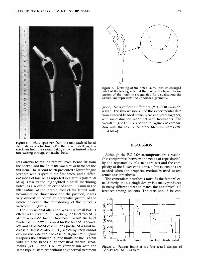
Figure 5. Left: a specimen from the first batch of holed stem, showing a fracture below the cement level; right: a specimen from the second batch, showing instead a frac- ture passing through the medial hole.
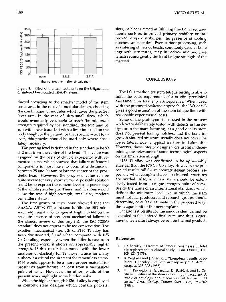
was always below the cement level, hence far from the pocket, and the finite life was similar to that of the full stem. The second batch presented a lower fatigue strength with respect to the first batch, and a differ- ent mode of failure, as reported in Figure 5 (440 * 70 MPa). Observation highlighted a small machining notch, as a result of an error of about 0.1 mm in the fillet radius, at the internal foot of the lateral wall. Because of the dimensions and the position, it was very difficult to obtain an acceptable picture of the notch; however, the morphology of the defect is sketched in Figure 6.
The dimensional alteration was very small but its effect was substantial. In Figure 7, the label “holed Ti stem” was used for the first batch, while the label “notched Ti stem” was used for the second. Theoret- ical and FEM-based calculations predicted a local in- crease of stress of about 13%, which by itself cannot explain the observed decrease in fatigue limit. Figure 8 reports the estimated fatigue limits for the Ti stem with sintered beads after industrial thermal treat- ments (B.U.S. or S.T.A.) in comparison with the same type of stem but without any thermal treatment
Figure 6. Drawing of the holed stem, with an enlarged detail of the tooling notch at the foot of the hole. The ex- tension of the notch is exaggerated for visualisation; the dashed line represents the unnotched geometry.
(none). No significant difference (P < .0001) was ob- served. For this reason, all of the experimental data from sintered beaded stems were analyzed together, with no distinction made between treatments. The overall fatigue limit is reported in Figure 7 in compar- ison with the results for other titanium stems (285 * 64 MPa).
DISCUSSION
Although the IS0 7206 assumptions are a reason- able compromise between the needs of reproducibil- ity and repeatability of a standard test and the com- plexity of the in vivo conditions, a few extensions are needed when the proposed method is used to test cementless prosthesis.
The cementless prosthesis must fit the femoral ca- nal directly; thus, a single design is usually produced in many different sizes to match the anatomical dif- ferences among patients. The tests should be con-
700, I I I I
Figure 7. Ti6A14V (ASTM F136) stem.
Fatigue limits of the four tested designs of
VICECONTI ET AL.
350
300
250
200
150
100
50
0 none B.U.S. S.T.A.
Thermal treatment after sinterization
Figure 8. of sintered bead-coated Ti6A14V stems.
Effect of thermal treatments on the fatigue limit
ducted according to the smallest model of the stem series and, in the case of a modular design, choosing the combination of modules which gives the greatest lever arm. In the case of ultra-small sizes, which would eventually be unable to reach the minimum strength required by the standard, the test may be run with lower loads but with a limit imposed on the body weight of the patient for that specific size. How- ever, this practice should be used only where abso- lutely necessary.
The potting level is defined in the standard to be 80 k 2 mm from the center of the head. This value was assigned on the basis of clinical experience with ce- mented stems, which showed that failure of femoral components is most likely to occur at a distance of between 25 and 90 mm below the center of the pros- thetic head. However, the proposed value can be quite severe for very short stems. A possible solution could be to express the cement level as a percentage of the whole stem length. These modifications would allow the test of high-strength, small-size, modern cementless stems.
The first group of tests have showed that the An.C.A. ASTM F75 ministem fulfills the IS0 mini- mum requirement for fatigue strength. Based on the absolute absence of any stem mechanical failure in the clinical review of this implant, the IS0 720613 standard does not appear to be too conservative. The excellent mechanical strength of F136 Ti alloy has been documented,15 and when compared with F75 Cr-Co alloy, especially when the latter is cast as in the present work, it shows an appreciably higher strength. If this result is summed with the lower modulus of elasticity for Ti alloys, which for many authors is a critical requirement for cementless stems, F136 would appear to be a more proper material for prosthesis manufacture, at least from a mechanical point of view. However, the other results of the present work highlight some hidden risks.
When the higher strength F136 Ti alloy is employed in complex stem designs which contain pockets,
slots, or blades aimed at fulfilling functional require- ments such as improved primary stability or im- proved stress distribution, the presence of tooling notches can be critical. Even surface processing, such as sintering of nets or beads, commonly used as bone ingrowth structures, may introduce micronotches which reduce greatly the local fatigue strength of the material.
CONCLUSIONS
The LOH method for stem fatigue testing is able to fulfill the basic requirements for in vitro preclinical assessment on total hip arthorplasties. When used with the proposed staircase approach, the IS0 7206/3 gives a good estimation of the stem fatigue limit with reasonable experimental costs.
Some of the prototype stems used in the present work were deliberately tested with defects in the de- sign or in the manufacturing, as a good-quality stem does not present tooling notches, and the bone in- growth sintered structure usually does not cover the lower lateral side, a typical fracture initiation site. However, these inferior designs were useful in deter- mining the relevance of some technological aspects on the final stem strength.
F236 Ti alloy was confirmed to be appreciably stronger than the F75 Cr-Co alloy. However, the pre- sented results call for an accurate design process, es- pecially when complex shapes or sintered structures are needed. Also, any new stem should be exten- sively tested from a fatigue strength point of view. Beside the limits of an international standard, which defines the minimum load level at which the stem must not fail, producers and research groups should determine, or at least estimate in the proposed way, the fatigue limit of the new implant.
Fatigue test results for the smooth stem cannot be extended to the sintered final stem, and thus, exper- imental tests must always be run on the real product.
References
1. J. Charnley, "Fracture of femoral prostheses in total hip replacement: A clinical study," Clin. Orthop., 111, 105-120 (1975). B. Wejkner and J. Stenport, "Long-term results of bi- lateral Charnley total hip arthroplasty," J. Arlhro- plasty, 3, 305-308 (1988). U. E. Pazzaglia, F. Ghisellini, D. Barbieri, and L. Ce- ciliani, "Failure of the stem in total hip replacement: A study of aetiology and mechanism of failure in 13 cases," Arch. Orthop. Trauma Surg., 107, 195-202 (1988).
2.
3.

FATIGUE STRENGTH OF CEMENTLESS HIP STEMS 881
4.
5.
6.
7.
8.
9.
10.
L. Munuera and E. Garcia Cimbrelo, “The femoral component in low friction arthroplasty after ten years,” Clin. Orthop., Jun, 163-175 (1992). P. Griss and G. Heimke, “Five years experience with ceramic metal composite hip endoprostheses. I. Clin- ical evaluation,” Arch. Orthop. Trauma Surg., 98, 157- 164 (1981). R. Kousbroek, P. Ducheyne, G. Van der Perre, E. Aer- noudt, and J. C. Mulier, ”Fracture hip prostheses due to welding defects,” Arch. Orthop. Trauma Surg., 98, 51-56 (1981). E. H. Miller, R. Shastri, and C. I. Shih, ”Fracture fail- ure of a forged vitallium prosthesis: A case report,” J. Bone Joint Surg. Am., 64, 1359-1363 (1982). C. A. Engh and P. Massin, “Cementless total hip ar- throplasty using the anatomic medullary locking stem: Results using a survivorship analysis,” Clin. Orthop., Dec, 141-158 (1989). L. F. Wilson, J. F. Nolan, and M. 8. Heywood Wad- dington, ”Fracture of the femoral stem of the Ring TCH hip prosthesis,” J . Bone Joint Surg. Br., 74, 7 2 5 728 (1992). G. Von Salis Soglio, W. Thomas, J. Haasters, and G. Bensmann, “Hip endoprosthesis shaft fractures: A
11.
12.
13.
14.
15.
clinical and technological material study,” Z . Orthop., 121, 74-80 (1983). M. A. Ritter and E. D. Campbell, “An evaluation of trapezoidal 28 femoral stem fractures,” Clin. Orthop.,
L. Marmor and T. A. Gruen, ”Stem fractures of extra heavy Cobra femoral hip prostheses: Report of two cases,” Clin. Orthop., Nov, 148-153 (1984). P. Ducheyne, M. Wevers, and P. De Meester, ”Fa- tigue properties of implant materials in hip prosthesis form: A standardized test,” J. Biomed. Mater. Res., 17, 45-57 (1983). P. K. Humphreys, J. F. Orr, and A. S. Bahrani, ”Test- ing of total hip replacements: Endurance tests and stress measurements,” Proc. Inst. Mech. Engrs., 204, 2941 (1990). J. Black, Orthopaedic Biornaterials in Research and Prac- tise. 1st edition, Churchill Livingstone, New York, 1988.
NOV, 237-244 (1986).
Received January 28, 1994 Accepted December 15, 1994