effects of liquefaction-induced ground …
TRANSCRIPT

SPECIAL ISSUE OF SOILS AND FOUNDATIONS 163-177, Sept. 1998
Japanese Geotechnical Society
EFFECTS OF LIQUEFACTION-INDUCED GROUND DISPLACEMENTS ON
PILE PERFORMANCE IN THE 1995 HYOGOKEN-NAMBU EARTHQUAKE
KOHJI TOKIMATSUi) and YOSHIHARU ASAKAn)
ABSTRACT
The field performance of various pile foundations that experienced soil liquefaction and lateral spreading in the 1995 Hyogoken-Nambu earthquake are summarized. It is found that (1) damage tends to occur in non-ductilepiles and at the interface between liquefied and nonliquefied layers; (2) the piles of a building near the waterfront show different failure modes in the direction perpendicular to the waterfront, while those away from the waterfront show similar deformation patterns. Cyclic and permanent ground displacements during and after earthquakes areestimated from field and aerial photographic surveys as well as analyses of strong motion records, and a simplified method for evaluating those displacements is presented. Pseudo-static analyses using p-y curves are conducted for well-document-ed case histories of pile foundations on which ground displacements estimated from the proposed method are im-
posed together with inertial forces from superstructures. The computed results agree reasonably well with the field per-formance of various pile foundations subjected to different ground movements. These findings confirm that the kinematic forces from cyclic and permanent ground displacements together with their spatial variation could have sig-nificant effects on pile damage. The proposed model could be effectively used to estimate deformation and stresses in
piles subjected to ground movements.
Key words: building, earthquake damage, lateral spreading, liquefaction, pile, p-y curve, subgrade reaction (IGC:E8)
INTRODUCTION
Extensive soil liquefaction that occurred in the Hyogoken-Nambu earthquake (M =7.2) of January 17, 1995, damaged various structures and infrastructures in the reclaimed land areas along the coastline of Kobe. In
particular, many of the quay walls in these areas moved up to several meters towards the sea due to liquefaction of their foundation soils and/or back-fills. This induced large horizontal ground movements as well as differential
ground settlements near the waterfront. As a result, not only buildings with spread foundations but also those supported on piles often settled and/ or tilted without sig- nificant damage to their superstructures. Similar damage
patterns were also observed at many buildings on liq- uefied level ground far away from the waterfront. There was a serious concern that the piles of those buildings might have been damaged. Excavation surveys after the
quake showed that this was the case for some pile heads. Integrity sonic testing further suggested that failures might have occurred at some depths other than pile heads. These findings indicate that the effects of liquefac-tion-induced ground movements on piles should be prop-
erly taken into account in foundation design. However, little is known concerning the actual failure and deforma-tion patterns of those piles, and their relation to ground displacements. The object of this study is to investigate the effects of soil liquefaction and lateral spreading on failure and deformation modes of piles, in an effort to im-
prove aseismic design of pile foundations and their remedial measures against liquefaction-induced ground deformations. For this purpose, the failure and deforma-tion modes of piles that experienced soil liquefaction and/or lateral spreading in the Kobe earthquake are sum-marized together with cyclic and permanent ground dis-
placements that might have developed during past earth-quakes. Pseudo-static analyses using p-y curves are then conducted for well-documented case histories of pile foundations from the Kobe earthquake.
PERFORMANCE OF NEAR-SURFACE SOILS AND PILE FOUNDATIONS IN THE 1995 HYOGOKEN-NAMBU EARTHQUAKE
Soil Liquefaction and Ground Motion CharacteristicsFigure 1 is a map showing the area of heavy damage to
i)Professor, Tokyo Institute of Technology, 2-12-1, O-okayama, Meguro-ku, Tokyo 152-8552.
ii) Graduate Student, ditto.
Manuscript was received for review on September 7, 1997.
Written discussions on this paper should be submitted before April 1, 1999 to the Japanese Geotechnical Society, Sugayama Bldg. 4F, Kanda
Awaji-cho 2-23, Chiyoda-ku, Tokyo 101-0063, Japan. Upon request the closing date may be extended one month.
163

164 TOKIMATSU AND ASAKA
buildings (Chuo-Kaihatsu, 1995) and the area where field manifestation of soil liquefaction was evident after the 1995 earthquake. Most of the buildings discussed in this
paper were located in reclaimed land areas including Port and Rokko Islands, Fukaehama, and Mikagehama where soil liquefaction extensively occurred. Liquefaction devel-oped to a lesser extent in central Port Island and southern Rokko Island where the fills had been treated or consisted of soils containing significant amounts of clay. Also shown in Fig. 1 are the particle orbits of ground dis-
placements that have been double-integrated from the
strong motion accelerograms obtained in those areas dur-ing the earthquake (CEORKA, 1995; Sekisui House, 1996). The peak cyclic ground displacements were 35 cm at a non-liquefied site on Rokko Island, and 46 cm and 55 cm near liquefied areas on Port Island and in Fukaehama. It is estimated that about two thirds of these displacements resulted from shear strains induced in the reclaimed fills. The acceleration response spectra for damping ratios of 10% range around 0.3-0.5 G for
periods less than 0.5 s, as shown in Fig. 2.
Fig. 1. Map showing distribution of structural damage and of liquefied area with particle orbits of ground displacement
Fig. 2. Response spectra of strong motion accelerograms observed in reclaimed lands

PILE PERFORMANCE DURING LIQUEFACTION 165
Characteristics of Piles for Building FoundationsThe piles used in the Kobe area for building founda-
tions are classified into precast concrete or steel pipe (S)
piles and east-in-place concrete piles. Most precast piles are hollow with outer diameters typically ranged from 35 to 60 cm, which contrasts with solid cast-in-place con-crete piles with diameters typically over 100 cm. The
precast concrete piles encountered in the Kobe area in-clude prestressed concrete (PC) piles used before the 1980s and prestressed high strength concrete (PHC) piles used after the 1980s. To strengthen the capacity and duc- tility, steel pipe reinforced concrete (SC) piles and rein-forced prestressed concrete (PRC) piles have been also used. Figure 3 shows the relations of bending moment with curvature for the piles discussed in this paper, and Table 1 summarizes their characteristics. Both PC and PHC piles have three different capacities for a given di-ameter, i.e., Types A, B, and C in ascending order of capacity. In the following, Mu is the bending moment at concrete crashing at extreme compression fiber of PC, PHC, and SC piles or at which compression fiber strain. of S piles reaches a limiting value; Myis the bending mo- ment at yielding of tension bars of PC and PHC piles or at yielding of steel at extreme tension fiber of SC and S
piles; and Mc. is the bending moment at concrete cracking at extreme tension fiber of PC and PHC piles.
Outlines of Pile Damage from Detailed Field Investiga-tion
A large number of performances of pile foundations during the Kobe earthquake have been presented, based on field investigation including excavation of pile heads (e.g., Kansai Branch of Architectural Institute Japan (AIJ), 1996; AIJ et al., 1998). In addition to integrity tests for piles, several methods were used for detecting pile damage below the ground surface. Borehole cameras (Oh-oka et al., 1996) have identified damage portions and severity, and inclinometers (Shamoto et al., 1996) have provided data to estimate deformed shapes with depth of precast hollow piles. The main findings from the field investigation are summarized below.
In the liquefied level ground; 1) most PC piles and many PHC piles bearing on firm strata below liquefied layers suffered severe damage often accompanied by set-tlement and/or tilting of their superstructures, while some PHC piles sustained little damage on Port and Rokko Islands; 2) failures of those piles concentrated near the bottom of liquefied layers as well as near the pile head; 3) in some PC and PHC piles, damage occurredFig. 3. Relation of bending moment with curvature of piles
Table 1. Characteristics of piles used in this study

166 TOKIMATSU AND ASAKA
only near the bottom of liquefied layers, with no damage near the pile head; 4) follower piles consisting of SC piles and PHC-A piles with or without design load also showed similar patterns of damage (Nagai, 1997; Horikoshi et al., 1996); 5) follower piles consisting of SC and PHC-B piles in Port Island, however, showed invisi-ble damage (Fujii et al., 1996); and 6) S piles and SC piles appeared to have experienced less damage (e.g., Japanese Association of Steel Pipe Piles (JASPP), 1996).
In the treated level ground in Port and Rokko Islands, either with or without apparent sign of liquefaction; 1) buildings supported on friction piles embedded within fills performed well, though they settled with the sur-rounding ground; (2) buildings supported on piles bear-ing on firm soils beneath the fills often had no apparent settlement while the surrounding ground settled to some extent, creating vertical gaps around the bases of many buildings.
In the area where liquefaction-induced lateral spread-
ing occurred, particularly along the waterfront of artiii-cial islands; 1) damage was not limited to PC and PHC
piles but extended to some S piles (Satake et al., 1997) and cast-in-place concrete piles with or without design load (Tokimatsu et al., 1996; Kuwabara and Yoneda, 1998); 2) damage to pile caps and foundation beams often preceded or accompanied damage to S and CC
piles themselves; 3) piles within a building near the water-front showed different failure and deformation modes in the direction perpendicular to the shoreline as shown in Fig. 4 (Tokimatsu et al., 1997), while those away from the waterfront showed similar deformation modes
(Satake et al., 1997); but 4) in both cases, when facing the span side of the building with the sea on the left, the sea side pile cap rotated clockwise, whereas the land side pile cap rotated counterclockwise (Oh-Oka et al., 1997b).
The above findings indicate that, in addition to horizontal forces and overturning moments imposed on
pile heads from superstructures, kinematic forces in-duced by dynamic and permanent ground displacements of liquefied and laterally spreading soils had a significant impact on pile damage.
ANALYTICAL METHOD FOR PILE PERFORMANCE
Inertial and Kinematic Forces Acting on PilesThe fundamental mechanisms of soil-pile-structure in-
teraction in liquefied soils were poorly understood. Cur-rent design approaches in Japan (AIJ, 1988; Japan Road Association (JRA), 1997) therefore involve crude sim-
plifications for representing lateral resistance of soils as well as lateral forces acting on piles. The p-y curve of liq-uefied soils is represented as a scaling of the static p-y curve of the soils, and the soil always resists piles to deform. In reality, however, large ground displacements may impose kinematic loads on piles, the effects of which are not taken into account in the current design codes.
Figure 5 schematically illustrates the soil-pile-structure interaction in liquefiable soils during and after an earth-
quake. Prior to the development of pore water pressure, only inertia forces from the superstructure may dominate
(Case I). With the development of pore pressure during shaking, the cyclic shear strain in the deposit increases,
producing large cyclic ground displacement. Thus, not only inertial forces but also kinematic forces resulting from cyclic ground displacements come to play im-
portant roles (Cases II). Towards the end of shaking, a residual component of shear strain may accumulate,
resulting in permanent horizontal ground displacement. At this stage, the intensity of ground shaking may be
negligibly small. As a result, kinematic forces due to per-manent ground displacements may have a dominant effect on pile performance (Case III) particularly near
I) During shaking before liquefaction
II) During shaking after liquefaction
III-a) Residual ground displacement after earthquake
III-13) Lateral ground displacement after earthquake
Fig. 4. Deformation of piles near waterfront detected by slope-indica-
tor
Fig. 5. Schematically figure showing soil-pile-structure interaction in liquefiable soils

PILE PERFORMANCE DURING LIQUEFACTION 167
quay walls which failed or moved seaward (Case III-b). Such permanent ground displacement may also occur even in a horizontally stratified soil deposit with the level
ground (Case III-a); however, it is generally less than and hardly ever exceeds the maximum cyclic ground displace-ment unless it is extremely loose. The above discussions indicate that piles in the level ground could suffer the most severe loading conditions in either Case I or II, whereas piles in laterally-spreading soils also experience severe loading condition in Case III. These loading condi-tions should be properly considered in stress and defor-mation analysis of piles in liquefiable soils.
Simplified Design MethodSimplified pseudo-static design methods using p-y
curves for pile foundations (AIJ, 1988; JRA, 1997), i.e., a single pile supported on nonlinear Winkler springs as shown in Fig. 6(a), are based on the following equation:
(1)
in which E and I are Young's modulus and moment of in-ertia of pile, y is horizontal displacement of pile, z is depth, k is coefficient of horizontal subgrade reaction, and B is pile diameter. The elastic value of k, ko, may be defined as (JRA, 1980):
(2)
in which B is pile diameter in cm, N is SPT N-value; and
the ultimate lateral resistance or pressure, Pmax, may be defined as:
(3)
in which o-'v0 is the initial effective confining pressure, and Kp is the Rankine passive earth pressure coefficient. The degradation of k with increasing displacement may be ex-
pressed as (e.g., Tokimatsu, 1997):
(4)
in which yi has to be equal to Pmax/ko. In addition, if liq-uefaction occurs, ko should be reduced according to ap-
propriate scaling factors (e.g., AIJ, 1990). When the ground displacement cannot be neglected,
Eq. (1) should be modified to (e.g., Nishimura, 1978; Tokimatsu and Nomura, 1991):
(5)
in which f(Z) is either cyclic or permanent ground dis-placement profile described later, which is applied to the pile through the p-y springs as shown in Fig. 6(b) or (c). In this case, y in Eq. (4) has to be replaced by yr=y-(z).
Tokimatsu (1997) examined the phase difference be-tween inertial and kinematic forces based on response analyses of a one-degree-of-freedom system and con-cluded that1) If Tb < Tg in which Tb and 1-`, are the natural periods of the building and the ground, respectively, inertial and kinematic forces tend to be in phase and thus both effects should be considered at the same time,2) If Tb Tg, inertial and kinematic forces tend to be
(a) (b) (c)
out of phase by 90 degrees and thus each effect may be considered separately, and3) If Tb > Tg, inertial force decreases and thus only the kinematic effect may be considered. Since Tb < Tg is gener-ally satisfied in the following case studies, the inertia and kinematic forces will be considered simultaneously.
CYCLIC AND PERMANENT GROUND DISPLACEMENTS DURING EARTHQUAKES
Cyclic and Permanent Shear Strains in Liquefied and Laterally Spreading Ground
One of the key factors in solving Eq. (5) involves the cyclic and permanent ground displacement profiles or shear strains to be developed in the liquefiable deposit un- der consideration. Simplified estimates of such shear strains have been presented by Tokimatsu and Yoshimi (1983), Seed et al. (1985), and Ishihara and Yoshimine (1992), as shown in Fig. 7. In these studies, however,
Fig. 6. Schematic figure showing simplified pseudo-static analysis us-
ing p-y curves for pile foundations
Fig. 7. Maximum possible shear strain induced during and after earth-
quakes

168 TOKIMATSU AND ASAKA
cyclic and permanent components of shear strain were not discriminated explicitly and thus whether the shear strains in the figure correspond to the cyclic or residual component is uncertain.
Ground displacements obtained from various methods after recent earthquakes including the one that hit the Kobe area, enable us to estimate cyclic and residual com-
ponents separately. For example, analyses of downhole strong motion array records permit estimates of cyclic shear strains (e.g., Tokimatsu and Koyamada, 1993; Kokusho et al., 1996). Aerial photographic surveys pro-vided ground surface displacements of both level and laterally-spreading ground after earthquakes (e.g., Hamada et al., 1996; Yasuda et al., 1997) and permanent displacements of damaged piles detected by a slope-indi-cator may also outline the degree of permanent ground
(a)
(b)
displacement (e.g., Shamoto et al., 1996; Oh-Oka et al., 1997a). Dividing these ground surface displacements by the thicknesses of liquefied layers at the sites leads to per-manent shear strains of the deposits in an approximate manner.
Figure 8 summarizes the relation of cyclic and perma-nent shear strains with adjusted SPT N-values from the results of those studies. In the figure, the permanent shear strains towards the sea near the waterfront are plot-ted in Fig. 8(b), while those in the level ground are plot-ted in Fig. 8(a) since they are considered to be equal to or less than the cyclic shear strain in the level ground. Also shown in Fig. 8(b) in the solid curve are the limiting shear strains from Fig. 7.
Figure 8 suggests that the shear strains shown in Fig. 7 do not indicate cyclic shear strains in the level ground but maximum possible permanent shear strains in laterally spreading soils, and that the cyclic shear strain, ycy, is only about 10-20% of ymax. This could produce a prelimi-nary chart for maximum cyclic shear strains to be devel-oped during earthquakes, as shown in Fig. 9.
The above finding permits estimates of a cyclic ground displacement profile of a liquefied deposit in a simplified manner as is the case in the liquefaction evaluations us-ing SPT N-values (e.g., Tokimatsu and Yoshimi, 1983; Seed et al., 1985):1) Determine adjusted SPT N-values, Na, and equiva-lent cyclic stress ratios during earthquake, Tad 6'v0, with depth.2) Estimate ;v from Fig. 9, with depth.3) Estimate a cyclic ground displacement profile, fcy(z), by integrating ycy upwards from the bottom of the liq-uefied layer, assuming ycydevelops in the same direc-tion. For example, when an 8-m thick sand layer with
Fig. 8. Field correlation of cyclic and permanent shear strains with ad-
justed SPT N-value: (a) cyclic shear strain, (b) permanent shear strain Fig. 9. Maximum cyclic shear strain during earthquakes

PILE PERFORMANCE DURING LIQUEFACTION 169
Na= 10 liquefies extensively (y,=4%), the resulting
ground surface displacement, Dcy, is estimated to be 32 cm.
For estimating a maximum possible permanent ground displacement profile, fr.(z); fcy(Z), Dcy, and Fig. 9 in the above procedure should be read as ymax,fma(z), Dmax, and Fig. 7, in which Dmax is maximum possible ground surface displacement.
Permanent Ground Displacement Near WaterfrontWhen lateral spreading occurs, the permanent horizon-
tal displacement of the ground surface takes a maximum value at the waterfront and decreases with distance from the waterfront. Thus, the maximum value together with its attenuation characteristics should be identified. Shamoto and Hotta (1996), Yasuda et al. (1997), Ishihara et. al. (1997) investigated horizontal and vertical
ground displacements near waterfront areas after the Hyogoken-Nambu earthquake. Figure 10 summarizes the relations between the horizontal ground surface dis-placement at the waterfront, Do, and the length of the laterally spreading area, L, both normalized in terms of the thickness of the liquefied layer, H. The relation be-
tween the two may be expressed as:
(6)
This indicates that lateral spreading may extend horizon-tally inland about 50 times the horizontal ground surface displacement at the waterfront.
Figure 11 shows a typical relation of horizontal ground displacement, D, with distance from the waterfront, x, from the studies by Shamoto and Hotta (1996), and Ishihara et al. (1997), in which D and x are normalized in terms of Do and L. The relation may be expressed as:
(7)
Assuming that L=50D0, the equation leads to
(8)
Figure 11, and Eqs. (7) and (8) show that the horizontal ground surface displacement in laterally spreading areas decreases to a half at x=LI5 and less than 1/ 5 at x=L/ 2. The permanent ground displacement profile at dis-tance x of a laterally spreading deposit, fis(z,x), may be approximated as:
for z <zm
(9)
for z > zw
(10)
(11)
in which z is depth below the ground surface, and zw is
depth of the groundwater table or the top of the liquefied
layer. Thus, once knowing Do, horizontal and vertical dis-
tributions of ground displacement may be estimated. In
reality, Do depends significantly on the type and seismic
design of quay walls as well as the strong motion charac-
teristics and soil conditions behind and below the quay
wall. It is conceivable, however, that the ground displace-
ment at the waterfront could be equal to a smaller value
of either the quay wall displacement or the maximum pos-
sible ground displacement behind the quay wall. Thus,
Do may be expressed as:
(12)
in which Dw is the displacement of the quay wall and Dmax is the maximum possible ground surface displacement of the liquefied soil determined by integrating ymax with depth. For example, if the quay wall moves seaward by 3 m with a 10-m thick liquefied sand layer having Na= 10(ymax= 40%) or 20(ymax= 10%), the permanent
ground displacement near the waterfront is expected to be 3 m or 1 m.
EFFECTS OF CYCLIC GROUND DISPLACEMENTS
ON PILE PERFORMANCE
While many PC and PHC piles in an extensively liq-
uefied area suffered severe damage, most piles of the
same types in the non-liquefied area in reclaimed lands
Fig. 10. Relation between horizontal displacement of waterfront and
length of laterally spreading area
Fig. 11. Relation of horizontal ground displacement with distance
from waterfront
170 TOKIMATSU AND ASAKA
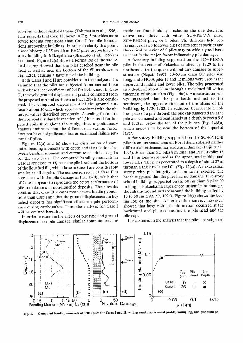
survived without visible damage (Tokimatsu et al., 1996). This suggests that Case II shown in Fig. 5 provides more severe loading conditions than Case I for pile founda-tions supporting buildings. In order to clarify this point, a case history of 35 cm diam PHC piles supporting a 4-story building in Mikagehama (Shamoto et al., 1997) is examined. Figure 12(c) shows a boring log of the site. A field survey showed that the piles cracked near the pile head as well as near the bottom of the fill as shown in Fig. 12(d), causing a large tilt of the building.
Both Cases I and II are considered in the analysis. It is assumed that the piles are subjected to an inertial force with a base shear coefficient of 0.4 for both cases. In Case II, the cyclic ground displacement profile computed from the proposed method as shown in Fig. 12(b) is also consid-ered. The computed displacement of the ground sur-face is about 36 cm, which appears consistent with the ob-served values described previously. A scaling factor for the horizontal subgrade reaction of 1 / 10 is used for liq-uefied soils throughout the study, since a preliminary
analysis indicates that the difference in scaling factordoes not have a significant effect on estimated failure pat-terns of piles.
Figures 12(a) and (e) show the distribution of com-
puted bending moments with depth and the relations be-tween bending moment and curvature at critical depths for the two cases. The computed bending moments in Case II are close to Mu near the pile head and the bottom of the liquefied fill, while those in Case I are considerably smaller at all depths. The computed result of Case II is consistent with the pile damage in Fig. 12(d), while that of Case I appears to reproduce the better performance of
pile foundations in non-liquefied deposits. These results confirm that Case II creates more severe loading condi-tions than Case I and that the ground displacement in liq-uefied deposits has significant effects on pile perform-ance during earthquakes. Thus, the analyses for Case I will be omitted hereafter.
In order to examine the effects of pile type and ground displacement on pile damage, similar computations are
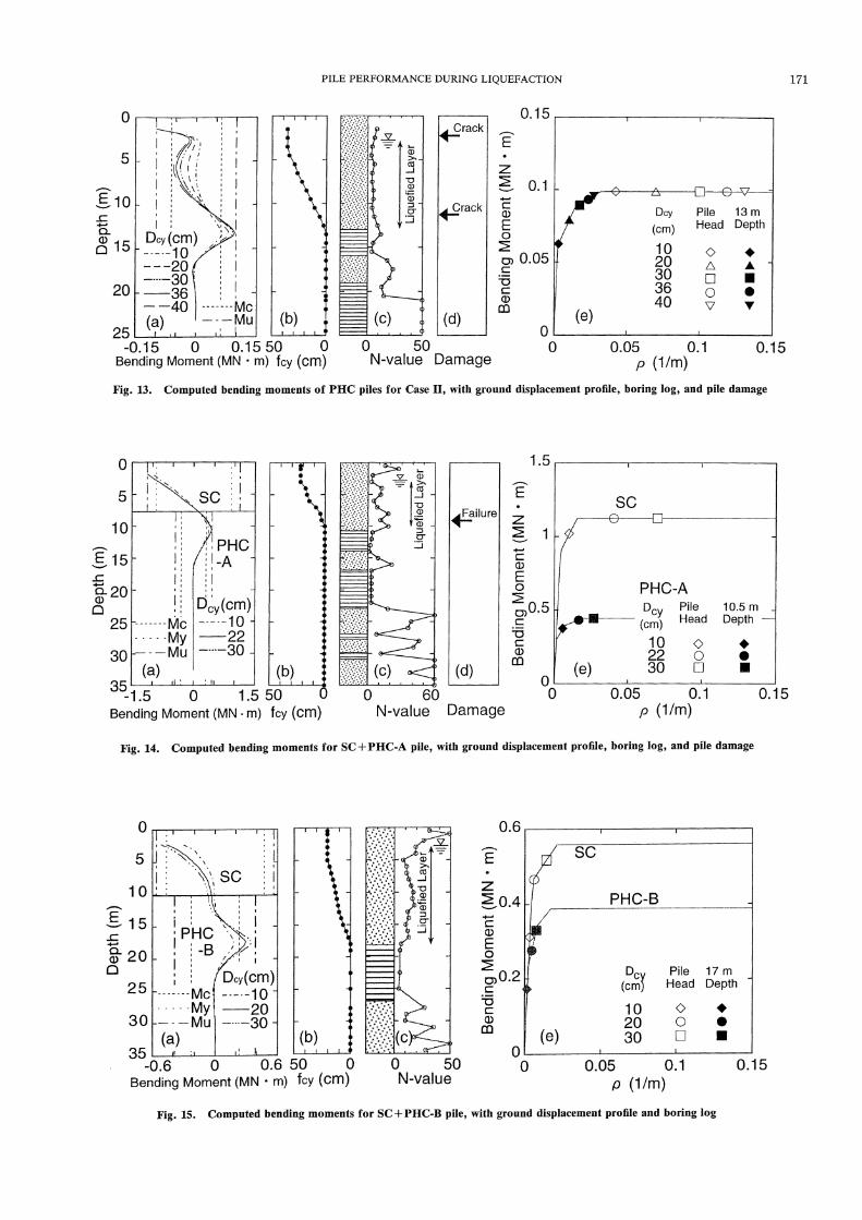
made for four buildings including the one described above and three with either SC + PHC-A piles, SC + PHC-B piles, or S piles. The different field per-formance of two follower piles of different capacities and the critical behavior of S piles may provide a good basis to identify the major factor influencing pile damage.
A five-story building supported on the SC + PHC-A piles in the center of Fukaehama tilted by 1/ 29 to the northeast after the quake without any damage to super-structure (Nagai, 1997). 50-60 cm diam SC piles 6 m long, and PHC-A piles 13 and 12 m long were used as the upper, and middle and lower piles. The piles penetrated to a depth of about 33 m through a reclaimed fill with a thickness of about 10 m (Fig. 14(c)). An excavation sur-vey suggested that the pile heads inclined to the southwest, the opposite direction of the tilting of the building, by 1/ 30-1/ 23. In addition, boring into a hol-low space of a pile through the pile cap suggested that the pile was damaged and bent largely at a depth between 9.6 and 11.3 m below the top of the pile cap (Fig. 14(d)), which appears to be near the bottom of the liquefied layer.
A four-story building supported on the SC + PHC-B
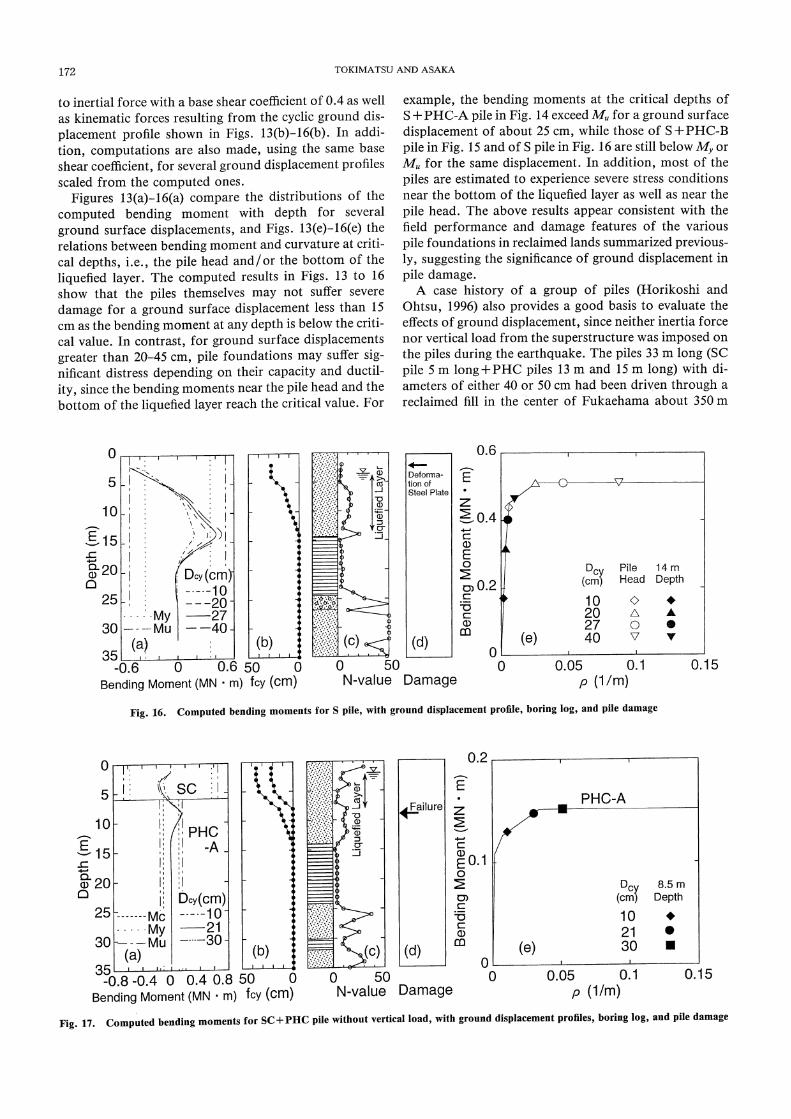
piles in an untreated area on Port Island suffered neither differential settlement nor structural damage (Fujii et al., 1996). 50 cm diam SC piles 8 m long, and PHC-B piles 13 and 14 m long were used as the upper, and middle and lower piles. The piles penetrated to a depth of about 37 m through a thick reclaimed fill (Fig. 15(c)). An excavation survey with pile integrity tests on some exposed pile heads suggested that the piles had no damage. Five-story school buildings supported on the 50 cm diam S piles 30 m long in Fukaehama experienced insignificant damage, though the ground surface around the building settled by 10 to 50 cm (JASPP, 1996). Figure 16(c) shows the bor-ing log of the site. An excavation survey, however, showed that large residual deformation occurred at the horizontal steel plate connecting the pile head and the pile cap.
It is assumed in the analysis that the piles are subjected
(a) (b) (c) (d) (e)
Fig. 12. Computed bending moments of PHC piles for Cases I and II, with ground displacement profile, boring log, and pile damage
PILE PERFORMANCE DURING LIQUEFACTION 171
(a) (b) (c) (d) (e)
(a) (b) (c) (d) (e)
(a) (b) (c) (e)
Fig. 13. Computed bending moments of PHC piles for Case II, with ground displacement profile, boring log, and pile damage
Fig. 14. Computed bending moments for SC + PHC-A pile, with ground displacement profile, boring log, and pile damage
Fig. 15. Computed bending moments for SC+ PHC-B pile, with ground displacement profile and boring log
172 TOKIMATSU AND ASAKA
to inertial force with a base shear coefficient of 0.4 as well as kinematic forces resulting from the cyclic ground dis-
placement profile shown in Figs. 13(b)-16(b). In addi-tion, computations are also made, using the same base shear coefficient, for several ground displacement profiles scaled from the computed ones.
Figures 13(a)-16(a) compare the distributions of the computed bending moment with depth for several ground surface displacements, and Figs. 13(e)-16(e) the relations between bending moment and curvature at criti-cal depths, i.e., the pile head and / or the bottom of the liquefied layer. The computed results in Figs. 13 to 16 show that the piles themselves may not suffer severe damage for a ground surface displacement less than 15 cm as the bending moment at any depth is below the criti-cal value. In contrast, for ground surface displacements greater than 20-45 cm, pile foundations may suffer sig-nificant distress depending on their capacity and ductil-ity, since the bending moments near the pile head and the bottom of the liquefied layer reach the critical value. For
example, the bending moments at the critical depths of S + PHC-A pile in Fig. 14 exceed Mu for a ground surface displacement of about 25 cm, while those of S + PHC-B
pile in Fig. 15 and of S pile in Fig. 16 are still below My or Mu for the same displacement. In addition, most of the
piles are estimated to experience severe stress conditions near the bottom of the liquefied layer as well as near the
pile head. The above results appear consistent with the field performance and damage features of the various
pile foundations in reclaimed lands summarized previous-ly, suggesting the significance of ground displacement in
pile damage.A case history of a group of piles (Horikoshi and
Ohtsu, 1996) also provides a good basis to evaluate the effects of ground displacement, since neither inertia force nor vertical load from the superstructure was imposed on the piles during the earthquake. The piles 33 m long (SC
pile 5 m long + PHC piles 13 m and 15 m long) with di-ameters of either 40 or 50 cm had been driven through a reclaimed fill in the center of Fukaehama about 350 m
(a) (b) (c) (d) (e)
(a) (b) (c) (d) (e)
Fig. 16. Computed bending moments for S pile, with ground displacement profile, boring log, and pile damage
Fig. 17. Computed bending moments for SC +PHC pile without vertical load, with ground displacement profiles, boring log, and pile damage

PILE PERFORMANCE DURING LIQUEFACTION 173
away from the shoreline. The pile heads were located at a depth between 0.5 and 1.5 m with a groundwater table of 2 m. The piles experienced the earthquake before place-ment of any pile caps or foundation beams and failed at a depth of about 8 m, i.e., the interface between gravelly medium sand with SPT N-values of 5 and gravelly coarse sand with SPT N-values of 12 (Figs. 17(c),(d)).
Figure 17(b) shows the estimated cyclic displacement profiles for two cases where soil liquefaction is assumed to have developed only in a loose fill above 8 m depth or throughout the fill. The pseudo-static analysis has been conducted without any inertial forces using the estimated cyclic displacement profiles and their scaling values. Figures 14(a) and (e) summarize the computed results only for the former case since it has yielded more severe stress conditions in the pile. The computed moments near the interface between liquefied and non-liquefied lay-ers reach the ultimate bending moment, Mu, for a groundrurface displacement of about 25 cm. The computedresult appears consistent with the observed damage pat-
tern of the pile, confirming the significant effects of cyclic
ground displacement in pile damage.
EFFECTS OF PERMANENT GROUND DISPLACEMENTS INDUCED BY LATERAL SPREADING
It is conceivable that the difference in the failure mode near the waterfront such as shown in Fig. 4 might have been induced by the variation of horizontal ground dis-
placements in the direction perpendicular to the shoreline such as shown in Fig. 11. The p-y analysis for a single pile cannot simulate such deformation patterns. Thus, an ana-lytical model shown in Fig. 18 is developed for Case III in which a group of piles connected with a foundation beam are subjected to permanent displacement profiles varying with distance from the waterfront.
First, case histories of two pile foundations in and around Fukaehama are examined. One building of three stories, supported on 40 cm diam PC piles 20 m long,
was situated 6 m from a quay wall that displaced by about 2 m towards the sea (Tokimatsu et al., 1997). Its span direction was perpendicular to the shoreline. Figure 19(d) shows a boring log of the site, which indi-cates that a loose fill 8-m thick might have liquefied dur-ing the earthquake. A field survey conducted after the
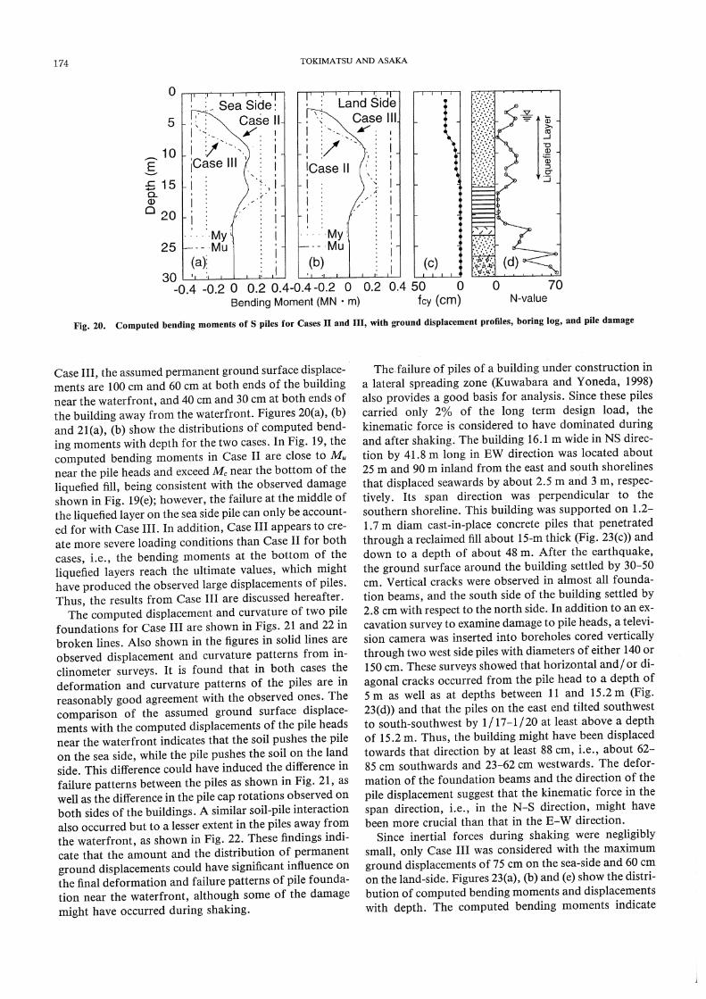
quake showed that the building had moved by about 80 cm and inclined by three degrees towards the sea, without any damage to its superstructure. An inclinome-ter survey also showed that the pile on the sea side was bent towards the sea with failures at three depths, i.e., the pile head, and the middle and bottom of the liquefied layer, while the pile on the land side inclined simply towards the sea with failures at two depths, i.e., the pile head and the bottom of the liquefied layer, as shown in Fig. 4. The other building of two stories, supported on 40.6 cm diam S piles, was situated about 100 m away from a quay wall on the north side that displaced by about 4 m. Its span direction was perpendicular to the northern shoreline. Figure 20(d) shows a boring log of the site. Despite minor damage to the superstructure, an inclinometer survey showed that the pile heads displaced northern seawards by 20 to 60 cm and western seawards by 20 to 80 cm. The deformation modes of the piles wi- thin the building are very similar, in contrast to those near the waterfront.
The analysis is performed in the span directions of the buildings for both Cases II and III. In Case II, a base shear coefficient of 0.4 is assumed with a cyclic ground displacement profile as shown in Fig. 19(c) or 20(c). In
(a) (b) (c) (d) (e)
Fig. 18. Analytical model of piles subjected to lateral spreading
Fig. 19. Computed bending moments of PC piles for Cases II and III, with ground displacement profiles, boring log, and pile damage
174 TOKIMATSU AND ASAKA
(a) (b) (c) (d)
Case III, the assumed permanent ground surface displace-ments are 100 cm and 60 cm at both ends of the building near the waterfront, and 40 cm and 30 cm at both ends of the building away from the waterfront. Figures 20(a), (b) and 21(a), (b) show the distributions of computed bend-ing moments with depth for the two cases. In Fig. 19, the computed bending moments in Case II are close to Mu near the pile heads and exceed M, near the bottom of the liquefied fill, being consistent with the observed damage shown in Fig. 19(e); however, the failure at the middle of the liquefied layer on the sea side pile can only be account-ed for with Case III. In addition, Case III appears to cre-ate more severe loading conditions than Case II for both cases, i.e., the bending moments at the bottom of the liquefied layers reach the ultimate values, which might have produced the observed large displacements of piles. Thus, the results from Case III are discussed hereafter.
The computed displacement and curvature of two pile foundations for Case III are shown in Figs. 21 and 22 in broken lines. Also shown in the figures in solid lines are observed displacement and curvature patterns from in-clinometer surveys. It is found that in both cases the deformation and curvature patterns of the piles are in reasonably good agreement with the observed ones. The comparison of the assumed ground surface displace-ments with the computed displacements of the pile heads near the waterfront indicates that the soil pushes the pile on the sea side, while the pile pushes the soil on the land side. This difference could have induced the difference in failure patterns between the piles as shown in Fig. 21, as well as the difference in the pile cap rotations observed on both sides of the buildings. A similar soil-pile interaction also occurred but to a lesser extent in the piles away from the waterfront, as shown in Fig. 22. These findings indi-cate that the amount and the distribution of permanent ground displacements could have significant influence on the final deformation and failure patterns of pile founda-tion near the waterfront, although some of the damage might have occurred during shaking.
The failure of piles of a building under construction in a lateral spreading zone (Kuwabara and Yoneda, 1998) also provides a good basis for analysis. Since these piles carried only 2% of the long term design load, the kinematic force is considered to have dominated during and after shaking. The building 16.1 m wide in NS direc-tion by 41.8 m long in EW direction was located about 25 m and 90 m inland from the east and south shorelines that displaced seawards by about 2.5 m and 3 m, respec-tively. Its span direction was perpendicular to the southern shoreline. This building was supported on 1.2-1.7 m diam cast-in-place concrete piles that penetrated through a reclaimed fill about 15-m thick (Fig. 23(c)) and down to a depth of about 48 m. After the earthquake, the ground surface around the building settled by 30-50 cm. Vertical cracks were observed in almost all founda-tion beams, and the south side of the building settled by 2.8 cm with respect to the north side. In addition to an ex-cavation survey to examine damage to pile heads, a televi-sion camera was inserted into boreholes cored vertically through two west side piles with diameters of either 140 or 150 cm. These surveys showed that horizontal and/ or di-agonal cracks occurred from the pile head to a depth of 5 m as well as at depths between 11 and 15.2 m (Fig. 23(d)) and that the piles on the east end tilted southwest to south-southwest by 1/17-1/ 20 at least above a depth of 15.2 m. Thus, the building might have been displaced towards that direction by at least 88 cm, i.e., about 62-85 cm southwards and 23-62 cm westwards. The defor-mation of the foundation beams and the direction of the
pile displacement suggest that the kinematic force in the span direction, i.e., in the N-S direction, might have been more crucial than that in the E-W direction.
Since inertial forces during shaking were negligibly small, only Case III was considered with the maximum
ground displacements of 75 cm on the sea-side and 60 cm on the land-side. Figures 23(a), (b) and (e) show the distri-bution of computed bending moments and displacements with depth. The computed bending moments indicate
Fig. 20. Computed bending moments of S piles for Cases II and III, with ground displacement profiles, boring log, and pile damage

PILE PERFORMANCE DURING LIQUEFACTION 175
(a) (b) (c) (d) (e)
that failures might have occurred near the bottom of the
liquefied layer as well as near the pile head, which shows
fairly good agreement with the field observation shown
in Fig. 23(d). In addition, the computed displacement of 55 cm of the pile head is consistent with the observed dis-
placement. These findings confirm that the amount and
Fig. 21. Computed displacements and curvatures of PC piles for Case III, compared with the observed values
Fig. 22. Computed displacements and curvatures of S piles for Case
III, compared with the observed values
Fig. 23. Computed bending moments and displacements of cast-in-place concrete piles, piles for Case III,with ground displacement profiles, bor-
ing log, and pile damage

176 TOKIMATSU AND ASAKA
the distribution of permanent ground displacements could have significant influence on the final deformation and failure patterns of pile foundations subjected to later-al spreading near the waterfront. Such effects therefore should be taken into account in the foundation design where lateral ground spreading is expected to occur.
CONCLUSIONS
Field performance of various pile foundations that ex-
perienced soil liquefaction and lateral spreading in the 1995 Hyogoken-Nambu earthquake have been compiled and summarized, together with their failure and deforma-tion modes identified by surveys using borehole cameras and/ or slope-indicators. Cyclic and residual shear strains in soil deposits during and after earthquakes have been estimated from field and aerial photographic sur-veys as well as analysis of strong motion records, and a simplified method for evaluating ground displacements has been developed. A simple p-y analysis using the
ground displacement profile from the proposed method has been conducted to evaluate pile performance during the earthquake. The field observation together with the analytical results leads to the following conclusions:
(1) The field investigation using a borehole camera and a slope-indicator has confirmed that failures of piles concentrated at the interface between liquefied and non-liquefied layers, as well as near the pile heads, indicating significant effects of ground displacements on pile damage.
(2) The failure and deformation patterns of piles in the lateral spread zone vary with distance from the water-front, probably due to the variation of lateral ground movements in the direction perpendicular to the water-front.
(3) Cyclic and permanent shear strains to de devel-oped in sands during earthquakes are expressed in terms of normalized SPT N-values. The cyclic shear strain is found to be about 10-20% of the maximum possible per-manent shear strain of the same sand.
(4) The simple p-y method combined with the proposed estimates for ground displacements can differentiate the damage from undamaged pile founda-tions subjected to cyclic and/ or permanent ground dis-placements in the Kobe earthquake and can simulate reasonably well the failure and deformation modes of damaged piles. This indicates that the ground deforma-tion could have played an important role on pile per-formance. Although preliminary and required further refinement and verification, the proposed model appears promising for evaluating the effects of ground displace-ments on piles.
ACKNOWLEDGMENTS
The study described herein was made possible through
the post-earthquake field investigation and their compila-
tion conducted by various organizations including but
not limited to the Committee on Building Foundation
Technology against Liquefaction and Lateral Spreading,
Japan Association for Building Research Promotion; the
Committees on Damage to Building Foundations in
Hyogoken-Nambu Earthquake, both Architectural In-
stitute of Japan and Kansai Branch of AIJ; and Japanese Association for Steel Pile Piles. The strong motion ac-
celerograms at the Higashi-Kobe Bridge station was pro-
vided by the Public Works Research Institute, Ministry
of Construction. Professor Fumio Kuwabara, Nippon In-stitute of Technology, kindly provided the information
concerning the case history of damaged cast-in-place con-
crete piles used in this paper. Miss Atsuko Niwano assist-
ed in conducting the psuedo-static analysis and preparing
the figures presented in this paper. The authors express
their sincere thanks to the above organizations and per-
sons.
NOTATIONS
B: pile diameter,Do: horizontal ground surface displacement at waterfront,
Du: cyclic ground surface displacement,Dmax: maximum possible horizontal ground displacement of
liquefied soil,bow: horizontal displacement of quay wall,E: Young's modulus of pile,
f (z): ground displacement profile,fu(z): cyclic ground displacement profile,
fis(z, x): permanent ground displacement profile,fmax(z): maximum possible ground displacement profile,
H: thickness of liquefied layer,I: moment of inertia of pile,k: coefficient of horizontal subgrade reaction of pile,ko: elastic value of k,Kp: Rankine passive earth pressure coefficient,L: length of laterally spreading area,M: bending moment,Mc: bending moment at concrete cracking at extreme tension
fiber of PC and PHC piles,Mu: bending moment at concrete crashing at extreme compres-
sion fiber of PC, PHC, and SC piles or at which compres-sion fiber strain of S pile reaches a limiting value,
My: bending moment at yielding of tension bars of PC and PHC piles or at yielding of steel at extreme tension fiber of SC and S piles,
N: SPT N-value,Na: adjusted SPT N-value,
Pmax: ultimate lateral resistance or pressure,Tb and Tg: natural periods of the building and the ground,
X: distance from the waterfront,y: horizontal displacement of pile,
Yi : reference displacement defined by Pm./ ko,yr: relative horizontal displacement between pile and groundz: depth,
zw: depth of groundwater table,σ60: initial effective confining pressure,
γcy: cyclic shear strain,
γmax: maximum possible shear strain,
τd/σ50: equivalent cyclic stress ratios during earthquake, and
ρ: curvature of pile.
REFERENCES
1) Architectural Institute of Japan (1988): "Recommendations for de-sign of building foundations," p. 430 (in Japanese).
2) Architectural Institute of Japan (1990): "Ultimate strength and

PILE PERFORMANCE DURING LIQUEFACTION 177
deformation capacity of buildings in seismic design," p. 715 (in Japanese).
3) Architectural Institute of Japan et al. (1998): "Report on the Hanshin-Awaji Earthquake Disaster," Building Series Volume 4, Wooden Structure and Building Foundations (in Japanese).
4) Chuo-Kaihatsu Corporation (1995): "Reconnaissance report on the 1995 Hyogoken-Nanbu earthquake-Great Hanshin Disaster," (Hyogoken-Nanbu earthquake).
5) Committee of Earthq. Obs. and Res. in the Kansai Area (CEOR-KA) (1995): "Digitized strong motion records in the affected area during the 1995 Hyogoken-Nanbu earthquake"
6) Fujii, S., Cubrinvski, M., Hayashi, T, Shimazu, S. and Tokimatsu, K. (1996): "Response analysis of buildings with a pile foundation on a liquefied ground," Proc., 31st Japan National Conf. on Geotech. Engrg., Vol. 1, pp. 1139-1140 (in Japanese).
7) Hamada, M., Isoyama, R. and Wakamatsu, K. (1995): "The 1995 Hyogoken-Nanbu (Kobe) earthquake," Liquefaction, ground dis-placement and soil condition in Hanshin area, Association for De-velopment of Earthquake Prediction, p. 194.
8) Horikoshi, K. and Ohtsu, H. (1996): "Investigation of PC piles damaged by the Hyogoken-nanbu earthquake," Proc., 31st Japan National Conf. on Geotechnical Engineering, Vol. 1, pp. 1227- 1228 (in Japanese).
9) Ishihara, K. and Yoshimine, M. (1992): "Evaluation of settlements in sand deposits following liquefaction during earthquakes," Soils and Foundations, Vol. 32, No. 1, pp. 173-188.
10) Ishihara, K., Yoshida, K. and Kato, M. (1997): "Lateral spreading of liquefied deposits during the 1995 Kobe earthquake," Proc., 3rd Kansai Int. Geotech. Forum on Comparative Geotech. Engrg., pp. 31-50.
11) Japanese Association for Steel Pile Piles (1996): "Investigation report on steel pipe pile foundations in the Hyogoken-Nambu earthquake- Part II," p. 156.
12) Japan Road Association (1980, 1997): "Specifications for road bridges," Vol. IV (in Japanese).
13) Kansai Branch of Architectural Institute of Japan (1996): "Report on case histories of damage to building foundations in Hyogoken-Nambu earthquake," Report presented by Committee on Damage to Building Foundations, p. 400 (in Japanese).
14) Kokusho, T., Sato, K. and Matsumoto, M. (1996): "Nonlinear dy-namic soil properties back-calculated from strong seismic motions during Hyogoken-nanbu earthquake," Proc., 11th World Conf. on Earthquake Engrg., CD-ROM Vol.4, p. 12.
15) Kuwabara, F. and Yoneda, K. (1998): "An investigation on the pile foundations damaged by liquefaction at the Hyogoken Nanbu earthquake," J. of Struct. Constr. Engrg., AIJ, No. 507 (in Japanese).
16) Nagai, K. (1997): "Lessons concerning foundation design in Hyogoken-nambu earthquake," Kenchiku Gijyutsu, No. 564, pp. 84-93 (in Japanese).
17) Nishimura, A. (1978): "Design of structures considering ground displacement," Kisoko, Vol. 6, No. 7, pp. 48-56 (in Japanese).
18) Oh-Oka, H., Iiba, M., Abe, A. and Tokimatsu, K. (1996): "Investi-
gation of earthquake-induced damage to pile foundation using
televiewer observation and integrity sonic tests," Tsuchi-to-kiso, JSG, Vol. 44, No. 3, pp. 28-30 (in Japanese).
19) Oh-Oka, H., Onishi, K., Nanba, S., Mori, T., Ishikawa, K., Koyama, S. and Shimazu, S. (1997a): "Liquefaction-induced failure of piles in 1995 Kobe earthquake," Proc., 3rd Kansai Int. Geotech. Forum on Comparative Geotech. Engrg., pp. 265-274.
20) Oh-Oka, H., Katoh, F. and Hirose, T. (1997b): "An investigation about damage to steel pipe pile foundations due to lateral spread-ing," Proc., 32nd Japan National Conf. on Geotech. Engrg., Vol. 1, pp. 929-930 (in Japanese).
21) Seed, H. B., Tokimatsu, K., Harder, L. F. and Chung, R. M.
(1985): "Influence of SPT procedures in soil liquefaction resistance evaluations," J. of Geotech. Engrg., Vol. 111, No. 12, pp. 1425- 1445.
22) Satake, K., Oh-Oka, H. and Tokimatsu, K. (1997): "Investigation of earthquake-induced damage to steel pipe pile foundation," Proc., 32nd Japan National Conf. on Geotech. Engrg., Vol. 1, pp. 927-928 (in Japanese).
23) Sekisui House (1996): "Rokko Island city, Strong motion record during the 1995 Hyogo-ken Nanbu earthquake and its analysis," (in Japanese)..
24) Shamoto, Y., Sato, M., Futaki, M. and Shimazu, S. (1996): "A site investigation of post-liquefaction lateral displacement of pile foundation in reclaimed land," Tsuchi-to-Kiso, JSG, Vol. 44, No. 3, pp. 25-27 (in Japanese).
25) Shamoto, Y. and Hotta, H. (1996): "Measurement of lateral ground displacement in Rokko Island," Proc., 31st Japan Nation-al Conf. on Geotech. Engrg., Vol. 1, pp. 1251-1252 (in Japanese).
26) Tokimatsu, K. and Yoshimi, Y. (1983): "Empirical correlation of soil liquefaction based on N-value and fines content," Soils and Foundations, Vol. 23, No. 4, pp. 56-74.
27) Tokimatsu, K. and Nomura, S. (1991): "Effects of ground defor-mation on pile stresses during soil liquefaction," J. of Struct. Con-str. Engrg., AIJ, No. 426, pp. 107-113 (in Japanese).
28) Tokimatsu, K. and Koyamada, K. (1993): "Dynamic soil proper-ties estimated from strong motion downhole array records (Part 2)," Proc., 28th Japan National Conf. on Geotech. Engrg., Vol. 1, pp. 1141-1142 (in Japanese).
29) Tokimatsu, K., Mizuno, H. and Kakurai, M. (1996): "Building damage associated with geotechnical problems," Soils and Founda-tions, Special Issue, pp. 219-234.
30) Tokimatsu, K., Oh-Oka, H., Shamoto, Y., Nakazawa, A. and Asaka, Y. (1997): "Failure and deformation modes of piles caused by liquefaction-induced lateral spreading in the 1995 Hyogoken-nambu earthquake," Proc., 3rd Kansai Int. Geotech. Forum on Comparative Geotech. Engrg., pp. 239-248.
31) Tokimatsu (1997): "Considerations of foundation design in liq-uefied and laterally-spreading ground," Kenchiku Gijyutsu, No. 564, pp. 126-131 (in Japanese).
32) Yasuda, S., Ishihara, K., Harada, K. and Nomura, H. (1997): "Area of ground flow occurred behind quay walls due to liquefac-
tion," Proc., 3rd Kansai Int. Geotech. Forum on Comparative Ge-otech. Engrg., pp. 85-93.